JP5489591B2 - Imaging apparatus and control method thereof - Google Patents
Imaging apparatus and control method thereof Download PDFInfo
- Publication number
- JP5489591B2 JP5489591B2 JP2009189332A JP2009189332A JP5489591B2 JP 5489591 B2 JP5489591 B2 JP 5489591B2 JP 2009189332 A JP2009189332 A JP 2009189332A JP 2009189332 A JP2009189332 A JP 2009189332A JP 5489591 B2 JP5489591 B2 JP 5489591B2
- Authority
- JP
- Japan
- Prior art keywords
- light emission
- exposure
- emission amount
- time
- exposure condition
- Prior art date
- Legal status (The legal status is an assumption and is not a legal conclusion. Google has not performed a legal analysis and makes no representation as to the accuracy of the status listed.)
- Expired - Fee Related
Links
- 238000003384 imaging method Methods 0.000 title claims description 42
- 238000000034 method Methods 0.000 title claims description 28
- 230000035945 sensitivity Effects 0.000 claims description 20
- 238000005259 measurement Methods 0.000 claims 5
- 238000001514 detection method Methods 0.000 description 10
- 238000012545 processing Methods 0.000 description 8
- 238000005375 photometry Methods 0.000 description 7
- 238000010304 firing Methods 0.000 description 4
- 238000012937 correction Methods 0.000 description 3
- 238000010586 diagram Methods 0.000 description 3
- 238000012935 Averaging Methods 0.000 description 2
- 238000004458 analytical method Methods 0.000 description 2
- 230000006870 function Effects 0.000 description 2
- 229910052724 xenon Inorganic materials 0.000 description 2
- FHNFHKCVQCLJFQ-UHFFFAOYSA-N xenon atom Chemical compound [Xe] FHNFHKCVQCLJFQ-UHFFFAOYSA-N 0.000 description 2
- 238000006243 chemical reaction Methods 0.000 description 1
- 230000006835 compression Effects 0.000 description 1
- 238000007906 compression Methods 0.000 description 1
- 230000006837 decompression Effects 0.000 description 1
- 238000011156 evaluation Methods 0.000 description 1
- CNQCVBJFEGMYDW-UHFFFAOYSA-N lawrencium atom Chemical compound [Lr] CNQCVBJFEGMYDW-UHFFFAOYSA-N 0.000 description 1
- 230000004044 response Effects 0.000 description 1
- 238000012552 review Methods 0.000 description 1
Images


Classifications
-
- G—PHYSICS
- G03—PHOTOGRAPHY; CINEMATOGRAPHY; ANALOGOUS TECHNIQUES USING WAVES OTHER THAN OPTICAL WAVES; ELECTROGRAPHY; HOLOGRAPHY
- G03B—APPARATUS OR ARRANGEMENTS FOR TAKING PHOTOGRAPHS OR FOR PROJECTING OR VIEWING THEM; APPARATUS OR ARRANGEMENTS EMPLOYING ANALOGOUS TECHNIQUES USING WAVES OTHER THAN OPTICAL WAVES; ACCESSORIES THEREFOR
- G03B15/00—Special procedures for taking photographs; Apparatus therefor
- G03B15/02—Illuminating scene
- G03B15/03—Combinations of cameras with lighting apparatus; Flash units
-
- G—PHYSICS
- G03—PHOTOGRAPHY; CINEMATOGRAPHY; ANALOGOUS TECHNIQUES USING WAVES OTHER THAN OPTICAL WAVES; ELECTROGRAPHY; HOLOGRAPHY
- G03B—APPARATUS OR ARRANGEMENTS FOR TAKING PHOTOGRAPHS OR FOR PROJECTING OR VIEWING THEM; APPARATUS OR ARRANGEMENTS EMPLOYING ANALOGOUS TECHNIQUES USING WAVES OTHER THAN OPTICAL WAVES; ACCESSORIES THEREFOR
- G03B7/00—Control of exposure by setting shutters, diaphragms or filters, separately or conjointly
- G03B7/08—Control effected solely on the basis of the response, to the intensity of the light received by the camera, of a built-in light-sensitive device
-
- H—ELECTRICITY
- H04—ELECTRIC COMMUNICATION TECHNIQUE
- H04N—PICTORIAL COMMUNICATION, e.g. TELEVISION
- H04N23/00—Cameras or camera modules comprising electronic image sensors; Control thereof
- H04N23/70—Circuitry for compensating brightness variation in the scene
- H04N23/73—Circuitry for compensating brightness variation in the scene by influencing the exposure time
-
- H—ELECTRICITY
- H04—ELECTRIC COMMUNICATION TECHNIQUE
- H04N—PICTORIAL COMMUNICATION, e.g. TELEVISION
- H04N23/00—Cameras or camera modules comprising electronic image sensors; Control thereof
- H04N23/70—Circuitry for compensating brightness variation in the scene
- H04N23/74—Circuitry for compensating brightness variation in the scene by influencing the scene brightness using illuminating means
Landscapes
- Engineering & Computer Science (AREA)
- Multimedia (AREA)
- Signal Processing (AREA)
- Physics & Mathematics (AREA)
- General Physics & Mathematics (AREA)
- Studio Devices (AREA)
- Stroboscope Apparatuses (AREA)
- Exposure Control For Cameras (AREA)
Description
本発明は、撮像装置に関するものであり、特にストロボ撮影時における撮像装置の露出制御に関する。 The present invention relates to an imaging apparatus, and more particularly to exposure control of the imaging apparatus during flash photography.
従来の撮像装置には、被写体が適正露出となるように自動露出制御を行い、適正露出とするために必要な露光時間が所定の露光時間より長い場合などにはストロボ撮影を行うものがある。そのような撮像装置では、ストロボ撮影時の最小露光時間は、ストロボ発光が行われている間に露光が終了されないように、ストロボの発光される可能性のある時間(最長発光時間)以上の長さになるように制御されている。 Some conventional image pickup apparatuses perform automatic exposure control so that a subject has proper exposure, and perform strobe shooting when an exposure time required for achieving proper exposure is longer than a predetermined exposure time. In such an imaging device, the minimum exposure time during flash photography is longer than the time that the flash may be emitted (the longest emission time) so that the exposure is not terminated while the flash is being emitted. It is controlled to be.
例えば、引用文献1では、カメラに接続される電子閃光装置の種類ごとに最長発光時間が異なることを考慮して、接続された電子閃光装置の最長発光時間に合わせてストロボ撮影時の最小露光時間を変更するカメラシステムが提案されている。
For example, in Cited
しかしながら、従来の撮像装置のような、電子閃光装置の最長発光時間に合わせてストロボ発光時の最小露光時間を設定する構成では、以下のような課題があった。例えば、日中逆光時のような背景が明るく主被写体が暗いシーンでは、ストロボを発光させて主被写体を適正露出にしようとすると、背景が適正露出となる露光時間よりも露光時間が長くなり背景の白飛びが発生してしまうという課題があった。 However, the configuration in which the minimum exposure time during strobe light emission is set in accordance with the longest light emission time of the electronic flash device as in the conventional imaging device has the following problems. For example, in a scene where the background is bright and the main subject is dark, such as when the subject is backlit in the daytime, if you try to make the main subject have proper exposure by firing the flash, the exposure time will be longer than the exposure time at which the background will have proper exposure. There was a problem that overexposure would occur.
また、背景の白飛びの発生を回避するために長くなった露光時間に対応させて絞りを小絞り側に変更させると、絞りを絞ることでストロボ光の到達距離の低下して主被写体に十分なストロボ光が到達せず主被写体が暗く撮影されてしまうという課題があった。 Also, if the aperture is changed to the small aperture side in response to the longer exposure time in order to avoid the occurrence of overexposure in the background, the range of the strobe light will be reduced and the main subject will be sufficient. There was a problem that the main subject was photographed darkly because the strobe light did not reach.
本発明は上記の課題を鑑みてなされたものであり、ストロボ撮影時に適正な露光時間とストロボ発光量で撮影を行い、ユーザにより好ましい画像を提供することを目的とする。 The present invention has been made in view of the above-described problems, and an object of the present invention is to provide a more preferable image for a user by performing shooting with an appropriate exposure time and flash emission amount during flash shooting.
上記目的を達成するために、本発明に係る撮像装置は、閃光発光を行う発光手段を用いたストロボ撮影が可能な撮像装置であって、測光手段と、前記測光手段の測光結果に基づいて、露光時間および絞り値を含むストロボ撮影時の露出条件を設定する設定手段と、前記測光手段の測光結果に基づいて、前記設定手段により設定された露出条件でストロボ撮影を行う際に必要となる前記発光手段の発光量を算出する発光量算出手段と、を有し、前記設定手段は、前記発光手段で発光可能な最大発光量の閃光発光を行うのに要する発光時間よりも短く、前記発光量算出手段により算出された発光量の閃光発光を行うのに要する発光時間よりも短くない時間をストロボ撮影時の露光時間として設定すること特徴とする。 In order to achieve the above object, an imaging apparatus according to the present invention is an imaging apparatus capable of performing flash photography using a light emitting unit that performs flash emission, and is based on a photometric unit and a photometric result of the photometric unit, Setting means for setting an exposure condition at the time of flash photography including an exposure time and an aperture value, and the above-mentioned necessary for performing flash photography with the exposure condition set by the setting means based on the photometry result of the photometry means A light emission amount calculating means for calculating a light emission amount of the light emission means, wherein the setting means is shorter than a light emission time required for performing flash light emission of the maximum light emission amount that can be emitted by the light emission means, and the light emission amount A time that is not shorter than the light emission time required for performing flash emission of the light emission amount calculated by the calculation means is set as the exposure time at the time of flash photography.
本発明によれば、ストロボ撮影時に適正な露光時間とストロボ発光量で撮影を行い、ユーザにより好ましい画像を提供することができる。 According to the present invention, it is possible to perform photographing with an appropriate exposure time and strobe emission amount at the time of strobe photographing, and to provide a more preferable image to the user.
(第1の実施例)
以下、本発明における第1の実施例について説明する。
図1は本実施例に係る撮像装置の構成を示したブロック図である。ユーザにより操作部112を介して撮影指示が行われると、システムコントローラ107は、撮影レンズ200の焦点位置や絞り機能を備えるシャッター201と撮像素子101、さらにストロボ撮影を行う際のストロボ装置210などを制御して撮影を行う。なお、本実施例では、ストロボ装置210は撮像装置に内蔵された内蔵ストロボとして説明を行うが、ストロボ装置210が撮像装置に着脱可能な外部ストロボ装置であっても構わない。
(First embodiment)
The first embodiment of the present invention will be described below.
FIG. 1 is a block diagram illustrating the configuration of the imaging apparatus according to the present embodiment. When a shooting instruction is given by the user via the operation unit 112, the
撮影が行われると、撮像素子101から画像信号が出力され、AFE(Analog Front End)回路150を通してバッファメモリ103に蓄えられる。
When shooting is performed, an image signal is output from the image sensor 101 and is stored in the
顔領域を検出する場合には、バッファメモリ103に蓄えられた画像信号から顔領域の座標を顔検出回路120にて検出する。また、撮像画面を複数分割してブロックごとに輝度値を算出する場合には、バッファメモリ103に蓄えられた画像信号から輝度値算出回路131にてブロックごとに輝度値が算出される。
When detecting the face area, the
システムコントローラ107は、顔検出結果や各ブロック輝度値などの情報からシーン解析を行い、ホワイトバランス補正係数や階調特性パラメータなど、様々な信号処理パラメータを信号処理回路140に設定する。信号処理回路140は、バッファメモリ103に蓄えられた画像信号に対して信号処理を行う。
The
画像記録が行われる場合には、バッファメモリ103内の画像信号は圧縮・伸長回路104に送られてJPEGファイルとして画像圧縮され、記録・読み出し部105によって記録媒体106に記録される。また、バッファメモリ103に蓄えられた画像信号に基づいて表示制御回路108によって表示画像が生成され、D/A変換部109を介して表示部110に表示される。
When image recording is performed, the image signal in the
顔検出回路120にて顔領域が検出された場合には、システムコントローラ107は、表示制御回路108に対して検出された顔領域に対して顔枠を表示するように指示を行う。
When the face area is detected by the
図2は、本実施例に係る撮像装置の撮影動作全体のシーケンスを示すフローチャートである。 FIG. 2 is a flowchart illustrating a sequence of the entire photographing operation of the imaging apparatus according to the present embodiment.
撮像装置の電源が投入されると、ステップS100で撮影レンズ200の繰り出し等の初期化動作が行われる。そして、ステップS101にて撮像素子101で撮像される画像を表示部110に逐次表示させるEVF(Electoric View Finder)動作に移行する。EVF動作中には、自動露出制御(Auto Exposure:AE)動作や自動合焦制御(Auto Focus:AF)動作も定期的に行われる。また、シーン判別や顔領域の検出(以下、顔検出とする。)などもEVF中に行われるものとする。ステップS102で、EVF中に電源がOFFされると撮影レンズ200の格納等の終了動作ステップS120が行われる。ステップS103でEVF動作中に操作部112に含まれるレリーズボタンが半押しされてSW1がONされると、ステップS104でAF動作、ステップS105ではAE動作がなされ、被写体輝度値(Bright Value:Bv)が取得される。システムコントローラ107は、Bv値や被写体の動き量などの検出結果から、撮影感度(Sensitive Value:Sv)や絞り値(Aperture Value:Av)やシャッター速度(Time Value:Tv)などの露出条件を決定する。このとき、露出条件はあらかじめ設定されたプログラム線図に従って決定される。また、システムコントローラ107は、撮像装置の設定が自動ストロボ発光を行う設定であれば、プログラム線図に従って決定されたシャッター速度が所定値より遅い場合、すなわち、露光時間が所定値より長い場合にはストロボ発光を行うと判定する。また、シーン判別により逆光シーンだと判定された場合にもストロボ発光を行うと判定する。
When the power of the imaging apparatus is turned on, an initialization operation such as extension of the taking
AE動作が終了するとステップS106でレリーズボタンが全押しされてSW2がONされるまで、システムコントローラ107はステップS108においてSW1のONされた状態が解除されたかどうかの判断を繰り返し行う。SW1がONされた状態(SW1保持中)は、ステップS105で決定された撮影感度、絞り値、シャッター速度、ストロボの発光の有無などが表示部110上に表示される。ステップS108でSW1のONされた状態が解除されたと判断すると、ステップS101に戻る。
When the AE operation ends, the
ステップS106でSW2がONされると、ステップS105においてストロボ発光を行うと判定されている場合には、ステップS111にてプリ発光が行われ、システムコントローラ107はプリ発光時の測光結果に基づいてステップS112で調光演算を行う。ステップS113で本露光が行われ、ステップS114では、本露光をして取得された画像信号に対する信号処理や記録媒体への記録を行う。そして、ステップS115において、撮影画像の確認のために撮影画像を予め決められた時間だけ表示部110に表示させるレックレビューがなされたのち、ステップS101に戻る。
When SW2 is turned on in step S106, if it is determined in step S105 that strobe light emission is to be performed, pre-light emission is performed in step S111, and the
次に、図3を用いて、本実施例におけるストロボ撮影時の撮影条件の決定処理について詳細に説明する。図3はストロボ撮影時の撮影条件を決定する際のフローチャートであり、図2に示したフローチャートのステップ104からステップS112の処理に対応している。
Next, with reference to FIG. 3, the photographing condition determination process at the time of flash photography in the present embodiment will be described in detail. FIG. 3 is a flowchart for determining shooting conditions at the time of flash photography, and corresponds to the processing from
ステップS200では、システムコントローラ107はAE動作によりTv値(AE_Tv)を決定する。具体的には、EVF動作中に所定の撮影条件で撮像を行い、取得した画像信号をバッファメモリ103に蓄え、その画像信号を複数のブロックに分割し、各ブロックごとに平均輝度値を算出する。その後、各ブロックごとに所定の重み付けを行って画面平均値(Y_Ave)を算出する。その場合、中央重点の重みを付けて画面平均値を算出する中央重点測光を行ってもよいし、顔検出の結果に応じて被写体領域に重点的に重みを付けるなど、被写体に応じた評価測光をしてもよいし、単純に画面平均値を算出する平均測光を行ってもよい。その画面平均値とAE制御の目標値(AE_Target)との差分を段数換算し(Delta_AE)、式1に従ってBv値を決定する。
Bv=Av+Tv−Sv+Delta_AE・・・・・ 式1
ここで、Delta_AE=Log(Y_Ave/AE_Target)/Log(2)とする。
In step S200, the
Bv = Av + Tv−Sv
Here, Delta_AE = Log (Y_Ave / AE_Target) / Log (2).
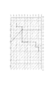
次に、決定したBv値からプログラム線図に従って、絞りとシャッター速度と撮影感度などからなる露出条件を決定する。図4は本実施例で用いるプログラム線図であって、点線は感度の変更を表しており、実線はシャッター速度および絞りの変更を表している。すなわち、Av=3で最も絞りが開いた状態となり、それ以上に絞りを開く必要がある場合には感度を変更させることを表している。 Next, an exposure condition including an aperture, a shutter speed, photographing sensitivity, and the like is determined from the determined Bv value according to a program diagram. FIG. 4 is a program diagram used in this embodiment. The dotted line represents the change in sensitivity, and the solid line represents the change in shutter speed and aperture. That is, when Av = 3, the aperture is in the most open state, and when the aperture needs to be opened more than that, the sensitivity is changed.
ステップS201では、システムコントローラ107は、ステップS200で決定されたシャッター速度や逆光判定の結果からストロボを発光させるか否かを判断する。例えば、シャッター速度が所定速度よりも遅い場合にストロボを発光させると判断してもよいし、画面解析の結果、背景が明るくて主被写体の顔領域が暗いなど、逆光シーンと判別された場合にストロボを発光させると判断してもよい。
In step S201, the
逆光判定について、判定方法の一例を図9を用いて説明する。図9では、撮像画面をA−Dの4つの領域に分割しており、それぞれの領域ごとに平均輝度値を算出する。また、顔検出により検出された主被写体の顔領域Fにおいても平均輝度値を算出する。そして、顔領域Fの輝度値と分割領域A−Dのそれぞれの輝度値とを比較し、分割領域A−Dのなかで顔領域Fの輝度値よりも所定値以上輝度値の高い領域が1つでもある場合には逆光シーンであると判別する。なお、逆光判定については、撮像画面の輝度値ヒストグラムを取得して、そのヒストグラムに基づいて逆光シーンの判別を行ったり、その他の公知の判定方法で行っても構わない。 An example of a determination method for backlight determination will be described with reference to FIG. In FIG. 9, the imaging screen is divided into four areas A to D, and an average luminance value is calculated for each area. An average luminance value is also calculated for the face area F of the main subject detected by face detection. Then, the luminance value of the face area F is compared with the luminance values of the divided areas AD, and one area having a luminance value higher than the luminance value of the face area F by a predetermined value in the divided areas AD is 1 If there is one, it is determined that the scene is a backlight scene. Note that the backlight determination may be performed by obtaining a luminance value histogram of the imaging screen and determining a backlight scene based on the histogram, or using other known determination methods.
ストロボを発光させない場合には、撮影条件の決定処理は終了となる。ストロボを発光させる場合には、ステップS202でシステムコントローラ107はストロボ撮影用の露出条件を決定する。ステップS200で決定されたシャッター速度が前記所定速度よりも遅い場合には、ストロボ撮影用のシャッター速度を前記所定速度としてその他の露出条件もプログラム線図に従って再び決定される。なお、ステップS200で決定されたシャッター速度が所定速度よりも速ければ、ステップS200で決定された露出条件をストロボ撮影用の露出条件として、ステップS202で新たに露出条件の決定を行わなくてもよい。その他、露出条件のうちのひとつをストロボ撮影用の露出条件として予め設定しておき、残りの露出条件をステップS200の測光結果に基づいて決定するようにしてもよい。
If the strobe is not fired, the shooting condition determination process ends. When the flash is emitted, the
ステップS203では、システムコントローラ107はステップS200あるいはステップS202で決定されたストロボ撮影用の露出条件からプリ発光用の露出条件を決定する。一般的なCCDを撮像素子とする場合、プリ発光用の画像信号を読み出すときには読み出し速度が速いセンサー駆動を行うため、画素加算および間引き率が大きい駆動を用いることがある。そのため本露光時とプリ発光時とで追従できる感度が変わる場合も存在するため、感度変化分だけ露出条件を変更する必要がある。なお、プリ発光を行う際の発光量は、Bv値ごとに予め決定された所定の発光量としてもよいし、あるいは、顔検出により求めた顔領域の大きさやAF動作の結果から被写体距離を推定し、その被写体距離に応じたプリ発光量としてもよい。もちろん、プリ発光時間はプリ発光時の露光時間に収まる範囲で決定しなければならないことは言うまでもない。
In step S203, the
ステップS204では、ステップS203で決定された露出条件でストロボ非発光状態で撮像し画像信号を取得する。ステップS205では、ステップS203で決定された露出条件でプリ発光を実際に行い画像信号を取得する。 In step S204, an image signal is acquired by capturing an image in the non-flash state under the exposure conditions determined in step S203. In step S205, pre-light emission is actually performed under the exposure conditions determined in step S203, and an image signal is acquired.
ステップS206では、輝度値算出回路131は、ステップS204で取得したストロボ非発光の画像信号とステップS205で取得した画像信号のそれぞれに対して、ブロックごとに輝度値を算出する。そして、ステップS207では、システムコントローラ107は、ストロボ非発光状態の輝度値とストロボ発光状態の輝度値の差分をブロックごとに算出し、画面内の測光方式に応じたブロックごとの重み付けをして加重加算平均した輝度値(Pre_Y)を算出する。同様に、ストロボ非発光状態の輝度をブロックごとに加重加算平均した輝度値(NoFlash_Y)を算出する。そして、加重加算平均されたそれぞれの輝度値を用いて、式2に従ってストロボの本発光量の算出を行う。
AE_Target=α×Pre_Y×C_PreFlash+Noflash_Y×C_Noflash・・・・式2
ここで、C_PreFlash=本発光時とプリ発光時との絞りおよび感度の差異を補正する補正値とし、C_Noflash=本発光時と非発光撮影時との絞り・感度およびシャッター速度の差異を補正する補正値とする。式2を満たすαをTv値やAv値などの段数と対応させるために段数換算を行い、段数換算された値をDelta_EFとする。
In step S206, the luminance
AE_Target = α × Pre_Y × C_PreFlash + Noflash_Y × C_Noflash...
Here, C_PreFlash = correction value for correcting the difference in aperture and sensitivity between main flash and pre-flash, and C_NoFlash = correction for correcting the difference in aperture / sensitivity and shutter speed between main flash and non-flash shooting. Value. The number of stages is converted in order to make α
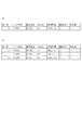
図5は、Delta_EFの値に対するストロボ発光時間を示した図である。図5(a)に示すグラフは縦軸がプリ発光時の発光量に対するDelta_EFの値であり、横軸はストロボの発光時間(単位はμSec)である。図5(b)のテーブルは、図5(a)のグラフにおいて点で示された位置の発光時間とDelta_EFの値の対応関係を示している。なお、Delta_EFの値はプリ発光時の発光量を基準とした段数で表されるため、プリ発光と同じ発光量では段数は0となり、プリ発光時よりも発光量が小さくなる10μSecなどは負の段数となる。 FIG. 5 is a diagram showing the strobe light emission time with respect to the value of Delta_EF. In the graph shown in FIG. 5A, the vertical axis represents the value of Delta_EF with respect to the light emission amount at the time of pre-light emission, and the horizontal axis represents the light emission time of the strobe (unit: μSec). The table of FIG. 5B shows a correspondence relationship between the light emission time at the position indicated by a point in the graph of FIG. 5A and the value of Delta_EF. Note that since the value of Delta_EF is represented by the number of steps based on the amount of light emitted during pre-emission, the number of steps is 0 for the same amount of light emission as that of pre-emission, and 10 μSec, which is smaller than the amount of light emitted during pre-emission, is negative. It becomes the number of steps.
次に、ステップS208では、システムコントローラ107は算出されたDelta_EFの値に基づいてストロボ発光時間を取得する。なお、ストロボ発光時間は図5(b)に示したようなテーブルを用いて取得してもよいし、発光量を発光時間に換算する式を用いてその都度算出するようにしてもよい。また、キセノン管を用いたストロボ装置では、キセノン管の発光特性上、発光停止指示後にも残光が発生するため、残光時間も含めてストロボ発光時間としてもよい。
Next, in step S208, the
ステップS209では、システムコントローラ107はステップS208で取得されたストロボ発光時間に同調可能な最も速いシャッター速度(Flash_Tv)を算出する。このとき、発光開始指示から実際に発光が開始するまでの時間に個体ばらつきが生じることを考慮してシャッター速度を算出するようにしてもよい。
In step S209, the
ステップS210では、システムコントローラ107は、上述のステップで決定された本発光時のストロボ発光量およびストロボ撮影用の露出条件がストロボ発光条件を満たすか否かを判定する。ここでのストロボ発光条件とは、本発光時のストロボ発光量がストロボ装置210で発光可能な発光量であること、ストロボ撮影用のシャッター速度がステップS209で算出されたシャッター速度と等しいまたは算出されたシャッター速度よりも遅いことである。ステップS207で決定された本発光時のストロボ発光量がストロボ装置210で発光可能な発光量よりも大きい場合、ストロボ発光を行っても十分な発光量が得られず被写体が暗い画像となってしまうため、ストロボ発光条件を満たさないと判定する。また、ステップS202で決定されたストロボ撮影用のシャッター速度がステップS209で算出されたシャッター速度よりも速い場合、ストロボ発光を行っている途中で露光終了し被写体が暗い画像となってしまうため、ストロボ発光条件を満たさないと判定する。上述した2つの条件をともに満たす場合はストロボ発光条件を満たすと判定し、ストロボ撮影時の撮影条件の決定処理を終了する。
In step S <b> 210, the
上述した2つの条件のいずれか1つでも満たさない場合はストロボ発光条件を満たさないと判定し、ステップS211でストロボ撮影用の露出条件を新たに算出する。このとき、絞りを1段開くことが発光量を1段上げることと等価であるため、決定された本発光時のストロボ発光量がストロボ装置210で発光可能な発光量よりも大きい場合には、絞りが開くように絞り値を変更する。また、絞りが開くように絞り値を変更するのに合わせて、式1を満たすためにシャッター速度が速くなるようにシャッター速度を変更する。さらに、シャッター速度を変更する場合には、ステップS209で算出されたシャッター速度よりも速くならないように、すなわち、露光時間が短くならないように変更する。以上のように、ステップS211では、絞り値とシャッター速度の関係が式1の関係を満たすように、かつ、シャッター速度がステップS209で算出されたシャッター速度よりも速くならないように、新たに絞り値およびシャッター速度を算出する。なお、本実施例では簡単のため、絞り値とシャッター速度のみを新たに算出する場合を説明するが、撮影感度を含めた3つの露出条件を新たに算出するようにしても構わない。
If any one of the two conditions described above is not satisfied, it is determined that the flash emission condition is not satisfied, and an exposure condition for flash photography is newly calculated in step S211. At this time, since opening the aperture one step is equivalent to increasing the light emission amount by one step, if the determined flash light emission amount during main light emission is larger than the light emission amount that can be emitted by the
次に、ステップS212では、新たに算出されたストロボ撮影用の露出条件に基づいて、ストロボ発光量も新たに算出する。なお、ここで新たに算出されるストロボ発光量は、新たに算出された絞り値が絞りを開くように変更されているため、ステップS207で算出されたストロボ発光量よりも大きい発光量となることはない。すなわち、ステップS212で新たに算出されたストロボ発光量に対応するシャッター速度は、ステップS209で算出されたシャッター速度よりも遅くなることはない。そのため、ステップS211で新たに算出されたシャッター速度が、ステップS212で新たに算出されたストロボ発光量に対応するシャッター速度よりも速くなることはない。 Next, in step S212, the flash emission amount is also newly calculated based on the newly calculated exposure condition for flash photography. Note that the newly calculated flash emission amount here is larger than the flash emission amount calculated in step S207 because the newly calculated aperture value has been changed to open the aperture. There is no. That is, the shutter speed corresponding to the strobe emission amount newly calculated in step S212 does not become slower than the shutter speed calculated in step S209. For this reason, the shutter speed newly calculated in step S211 does not become faster than the shutter speed corresponding to the flash emission amount newly calculated in step S212.
ステップS212で新たにストロボ発光量が算出されると、ステップS208に戻る。その後、新たに算出された本発光時のストロボ発光量およびストロボ撮影用の露出条件に基づいてストロボ発光条件を満たすか否かの判定が行われる。 When the flash emission amount is newly calculated in step S212, the process returns to step S208. Thereafter, it is determined whether or not the flash emission condition is satisfied based on the newly calculated flash emission amount at the time of main flash and the exposure condition for flash photography.
次に、図6を用いてストロボ撮影時の露出条件およびストロボ発光量の設定例について説明する。なお、図6では簡単のため、撮影感度はISO100で変更しないものとする。
Next, an example of setting exposure conditions and flash emission amount during flash photography will be described with reference to FIG. In FIG. 6, for the sake of simplicity, it is assumed that the photographing sensitivity is not changed by
測光結果がBv=11であった場合、ステップS200においてプログラム線図に従って露出条件の決定を行うと、図4に示すようにAv=5、Tv=10となる。これを絞り値とシャッター速度に換算すると、図6(a)に示すように絞り値=5,6となり、シャッター速度=1/1000秒となる。次に、逆光シーンと判別されてストロボを発光させると判断されると、ステップS202においてストロボ撮影用の露出条件が決定される。ここでは、ストロボ撮影用のシャッター速度として予め所定のシャッター速度が決められているものとし、ストロボ撮影用シャッター速度=1/500秒とする。このとき、ストロボ装置210の最長発光時間以上の時間のシャッター速度がストロボ撮影用シャッター速度として予め決められているものとする。他の露出条件もプログラム線図に従って決定され、絞り値=8となる。このようにして決定されたストロボ撮影用の露出条件(ストロボ撮影時の発光量の算出に用いる算出用露出条件)に基づいてステップS207で発光量算出が行われ、算出結果としてDelta_EF=6段が得られたとする。
If the photometric result is Bv = 11 and exposure conditions are determined according to the program diagram in step S200, Av = 5 and Tv = 10 as shown in FIG. When this is converted into an aperture value and a shutter speed, as shown in FIG. 6A, the aperture value = 5, 6 and the shutter speed = 1/1000 second. Next, when it is determined that the scene is a backlight scene and it is determined that the strobe light is emitted, an exposure condition for strobe shooting is determined in step S202. Here, it is assumed that a predetermined shutter speed is determined in advance as the shutter speed for flash photography, and the shutter speed for flash photography = 1/500 seconds. At this time, it is assumed that the shutter speed for a time longer than the longest light emission time of the
次に、ステップS208において、ステップS207で算出されたストロボ発光量をストロボ発光時間に換算することになるが、ステップS207で算出されたストロボ発光量がストロボ装置210の最大発光量を上回っているためストロボ発光時間に換算できない。そこで、このような場合にはストロボ装置210の最長発光時間をストロボ発光時間とし、ストロボ発光時間=1200μSecとする。このときの露出条件と発光量(第1の発光量)をまとめると、図6(b)のようになる。
Next, in step S208, the flash emission amount calculated in step S207 is converted into the flash emission time, but the flash emission amount calculated in step S207 exceeds the maximum flash emission amount of the
次に、ステップS210でストロボ発光条件を満たすか否かの判定が行われるが、ステップS207で算出されたストロボ発光量がストロボ装置210で発光可能な発光量ではないため、ストロボ発光条件を満たさないと判定される。
Next, it is determined in step S210 whether or not the flash emission condition is satisfied. However, since the flash emission amount calculated in step S207 is not the emission amount that can be emitted by the
そこで、ステップS211において、前述した条件に基づいて新たに露出条件算出を行うと、絞り値=6,2となり、シャッター速度=1/830秒となる。ここで、ステップS208で求めた発光時間と新たに算出したシャッター速度を比較すると、新たに算出したシャッター速度=1/830秒≒1205μSecでステップS208で求めた発光時間以上の時間であることがわかる。また、新たに算出したシャッター速度は、ストロボ装置210の最長発光時間以下の時間となる。そして、ステップS212において、ステップS211で新たに算出された露出条件に基づいて新たにストロボ発光量を算出すると、Delta_EF=5,26段となる。このときの露出条件と発光量(第2の発光量)をまとめると、図6(c)のようになる。
Therefore, when the exposure condition is newly calculated based on the above-described conditions in step S211, the aperture value = 6, 2 and the shutter speed = 1/830 seconds. Here, when the light emission time obtained in step S208 is compared with the newly calculated shutter speed, it can be seen that the newly calculated shutter speed = 1/830 seconds≈1205 μSec, which is longer than the light emission time obtained in step S208. . In addition, the newly calculated shutter speed is a time equal to or shorter than the longest light emission time of the
ステップS208に戻り新たに算出されたストロボ発光量をストロボ発光時間に換算し、ステップS209でストロボ発光条件を満たすか否かの判定を行うと、ストロボ発光量およびストロボ撮影用の露出条件のいずれもストロボ発光条件を満たすことになる。 Returning to step S208, the newly calculated flash emission amount is converted into the flash emission time, and if it is determined in step S209 whether the flash emission condition is satisfied, both the flash emission amount and the exposure condition for flash photography are obtained. The flash emission condition is satisfied.
以上のようにしてストロボ撮影時の露出条件およびストロボ発光量を決定することで、日中逆光時のような背景が明るく主被写体が暗いシーンであっても、背景を白飛びさせることなく主被写体が適正露出となるように撮影することができる。 By determining the exposure conditions and flash output during flash photography as described above, the main subject can be displayed without causing the background to be overexposed even when the background is bright and the main subject is dark, such as during daylighting. Can be taken so that the exposure becomes appropriate.
(第2の実施例)
第2の実施例は、第1の実施例と異なり、ストロボ撮影用の露出条件とストロボ発光量の組み合わせを複数算出して、その中から最適な組み合わせを選択する構成としている。なお、第2の実施例は、第1の実施例とストロボ撮影時の撮影条件の決定処理だけが異なるので、その他の説明は省略する。
(Second embodiment)
Unlike the first embodiment, the second embodiment is configured to calculate a plurality of combinations of exposure conditions for strobe shooting and the amount of flash emission, and to select the optimum combination from them. Since the second embodiment is different from the first embodiment only in the shooting condition determination process at the time of flash shooting, other description is omitted.
図7は、本実施例におけるストロボ撮影時の撮影条件の決定処理についてのフローチャートであり、図3と同様の処理を行うステップは同じ符号をつけ詳細な説明は省略する。 FIG. 7 is a flowchart of the shooting condition determination process at the time of flash shooting in this embodiment. Steps for performing the same process as in FIG. 3 are given the same reference numerals and detailed description thereof is omitted.
ステップS210でストロボ発光条件を満たさないと判定されると、ステップS311では、システムコントローラ107はストロボ撮影用の露出条件の組み合わせを複数算出する。ここで、ステップS207で決定された本発光時のストロボ発光量がストロボ装置210で発光可能な発光量よりも大きい場合、ストロボ発光量が小さくなるように絞りを開く方向に絞り値を変更し、組み合わせを算出する。また、ステップS200あるいはS202で決定されたストロボ撮影用のシャッター速度がステップS209で算出されたシャッター速度よりも速い場合も同様に、絞りを開く方向に絞り値を変更し組み合わせを算出する。なぜなら、ストロボ撮影用のシャッター速度を遅くするかストロボ発光時間に対応するシャッター速度を速くする必要があるが、いずれの場合も絞りを絞るように絞り値を変更することがないためである。ただし、この段階ではストロボ発光条件を満たす組み合わせか否かに係わらず組み合わせを算出するのであれば、絞りを絞る方向に絞り値を変更して組み合わせを算出しても構わない。
If it is determined in step S210 that the flash emission condition is not satisfied, in step S311, the
そして、ステップS312では、ステップS311で算出された各組み合わせごとにストロボ発光量を算出し、ステップS313でそれぞれのストロボ発光量をストロボ発光時間に換算する。 In step S312, the flash emission amount is calculated for each combination calculated in step S311. In step S313, each flash emission amount is converted into the flash emission time.
その後、ステップS314では、システムコントローラ107は、算出された複数のストロボ撮影用の露出条件とストロボ発光量の組み合わせから適正な組み合わせを選択する。
Thereafter, in step S314, the
次に、図8を用いてストロボ撮影時の露出条件およびストロボ発光量の設定例について説明する。測光結果がBv=11であった場合、ステップS200においてプログラム線図に従って露出条件の決定を行うと、図4に示すようにAv=5、Tv=10となる。これを絞り値とシャッター速度に換算すると、図8(a)に示すように絞り値=5,6となり、シャッター速度=1/1000秒となる。次に、逆光シーンと判別されてストロボを発光させると判断されると、ステップS202においてストロボ撮影用の露出条件が決定される。ここでは、ストロボ撮影用の露出条件として、ステップS200で決定された露出条件を用いるものとする。そして、このストロボ撮影用の露出条件に基づいてステップS207でストロボ発光量が算出され、算出結果としてDelta_EF=6段が得られたとする。 Next, an example of setting exposure conditions and flash emission amount during flash photography will be described with reference to FIG. If the photometric result is Bv = 11 and exposure conditions are determined according to the program diagram in step S200, Av = 5 and Tv = 10 as shown in FIG. When this is converted into an aperture value and a shutter speed, as shown in FIG. 8A, the aperture value = 5, 6 and the shutter speed = 1/1000 second. Next, when it is determined that the scene is a backlight scene and it is determined that the strobe light is emitted, an exposure condition for strobe shooting is determined in step S202. Here, the exposure condition determined in step S200 is used as the exposure condition for flash photography. Then, it is assumed that the strobe light emission amount is calculated in step S207 based on the exposure condition for the strobe photographing, and Delta_EF = 6 steps is obtained as a calculation result.
次に、ステップS208において、ステップS207で算出されたストロボ発光量をストロボ発光時間に換算することになるが、ステップS207で算出されたストロボ発光量がストロボ装置210の最大発光量を上回っているためストロボ発光時間に換算できない。そこで、このような場合にはストロボ装置210の最長発光時間をストロボ発光時間とし、ストロボ発光時間=1200μSecとする。
Next, in step S208, the flash emission amount calculated in step S207 is converted into the flash emission time, but the flash emission amount calculated in step S207 exceeds the maximum flash emission amount of the
次に、ステップS210でストロボ発光条件を満たすか否かの判定が行われるが、ステップS207で算出されたストロボ発光量がストロボ装置210で発光可能な発光量ではないため、ストロボ発光条件を満たさないと判定される。
Next, it is determined in step S210 whether or not the flash emission condition is satisfied. However, since the flash emission amount calculated in step S207 is not the emission amount that can be emitted by the
そこで、ステップS311において、ストロボ撮影用の露出条件の組み合わせを複数算出し、ステップS312で各組み合わせごとにストロボ発光量およびストロボ発光時間を取得する。このときの露出条件と発光量の組み合わせをまとめると、図8(b)のようになる。図8(b)からストロボ発光条件を満たす組み合わせが2つ存在することがわかる。 Therefore, in step S311, a plurality of combinations of exposure conditions for flash photography are calculated, and in step S312, the flash emission amount and the flash emission time are acquired for each combination. The combinations of exposure conditions and light emission amounts at this time are summarized as shown in FIG. It can be seen from FIG. 8B that there are two combinations that satisfy the strobe emission condition.
ステップS314において、算出された組み合わせから最適な組み合わせを選択することになるが、図8(b)における絞り値=2,8の組み合わせを選択することで、ストロボの発光による電池の消耗を最小限に抑えることができる。すなわち、最も絞り値が小さい露出条件の組み合わせを選択することで、ストロボ撮影時に絞りをより開くことになり、絞りを開くことで必要となる発光量を少なくすることができ、結果としてストロボの発光による電池の消耗を最小限に抑えることができる。あるいは、できるだけ被写界深度を浅くしたくない場合には絞り値=4の組み合わせを選択することで、ユーザーにより好ましい画像を撮影することができる。このように、ストロボ発光条件を満たす組み合わせが複数存在する場合には、撮影シーンや撮影モードに応じてより最適な組み合わせを選択するようにしたり、電池残量が少ない場合にはより電池の消耗が少なくてすむ組み合わせを選択するようにしてもよい。 In step S314, an optimum combination is selected from the calculated combinations. By selecting the combination of aperture values = 2 and 8 in FIG. 8B, battery consumption due to flash emission is minimized. Can be suppressed. In other words, by selecting the combination of exposure conditions with the smallest aperture value, the aperture can be further opened during flash photography, and the required amount of light emission can be reduced by opening the aperture, resulting in the flash firing. Battery consumption due to can be minimized. Alternatively, when it is not desired to make the depth of field as shallow as possible, a combination of aperture value = 4 can be selected to capture a more preferable image for the user. In this way, when there are multiple combinations that satisfy the flash emission condition, the most appropriate combination is selected according to the shooting scene and shooting mode, or when the remaining battery level is low, the battery is consumed more. A combination that requires less may be selected.
以上のようにしてストロボ撮影時の露出条件およびストロボ発光量を決定することで、日中逆光時のような背景が明るく主被写体が暗いシーンであっても、背景を白飛びさせることなく主被写体が適正露出となるように撮影することができる。また、複数の組み合わせを算出することで撮影シーンに応じてより最適な組み合わせを選択することができ、ユーザーにより好ましい画像を撮影することができる。 By determining the exposure conditions and flash output during flash photography as described above, the main subject can be displayed without causing the background to be overexposed even when the background is bright and the main subject is dark, such as during daylighting. Can be taken so that the exposure becomes appropriate. Further, by calculating a plurality of combinations, a more optimal combination can be selected according to the shooting scene, and a more preferable image can be shot by the user.
なお、上述の2つの実施例では、撮像素子から出力される画像信号に基づいて測光を行う構成であったが、撮像素子とは別に測光センサを設けて、該測光センサの出力に基づいて測光を行うようにしてもよい。 In the above-described two embodiments, photometry is performed based on the image signal output from the image sensor. However, a photometric sensor is provided separately from the image sensor, and photometry is performed based on the output of the photometer sensor. May be performed.
また、上述の2つの実施例において、ストロボ発光条件を満たす露出条件およびストロボ発光量の組み合わせが存在しない場合には、撮影シーンやユーザーの設定に応じてどの組み合わせでストロボ撮影を行うか決定すればよい。例えば、主被写体を優先させる場合には、背景が白飛びするような露光時間になったとしても主被写体が適正露出となる組み合わせを選択すればよい。反対に、背景を優先させる場合には、発光量が十分でなく主被写体が暗くなったとしても背景が適正露出となる組み合わせを選択すればよい。 Further, in the above-described two embodiments, when there is no combination of exposure conditions and flash emission amounts that satisfy the flash emission conditions, it is possible to determine which combination is used for flash photography according to the shooting scene and user settings. Good. For example, when giving priority to the main subject, it is only necessary to select a combination that allows the main subject to be properly exposed even when the exposure time is such that the background is overexposed. On the other hand, when giving priority to the background, it is only necessary to select a combination in which the background is appropriately exposed even if the light emission amount is not sufficient and the main subject becomes dark.
(その他の実施例)
また、本発明は、以下の処理を実行することによっても実現される。即ち、上述した実施例の機能を実現するソフトウェア(プログラム)を、ネットワーク又は各種記憶媒体を介してシステムあるいは装置に供給し、そのシステムあるいは装置のコンピュータ(またはCPUやMPU等)がプログラムを読み出して実行する処理である。
(Other examples)
The present invention can also be realized by executing the following processing. That is, software (program) for realizing the functions of the above-described embodiments is supplied to a system or apparatus via a network or various storage media, and a computer (or CPU, MPU, etc.) of the system or apparatus reads the program. It is a process to be executed.
101 撮像素子
103 バッファメモリ
107 システムコントローラ
112 操作部
120 顔検出回路
131 輝度値算出回路
140 信号処理回路
201 シャッター
210 ストロボ装置
DESCRIPTION OF SYMBOLS 101 Image pick-up
Claims (17)
測光手段と、
前記測光手段の測光結果に基づいて、露光時間および絞り値を含むストロボ撮影時の露出条件を設定する設定手段と、
前記測光手段の測光結果に基づいて、前記設定手段により設定された露出条件でストロボ撮影を行う際に必要となる前記発光手段の発光量を算出する発光量算出手段と、を有し、
前記設定手段は、前記発光手段で発光可能な最大発光量の閃光発光を行うのに要する発光時間よりも短く、前記発光量算出手段により算出された発光量の閃光発光を行うのに要する発光時間よりも短くない時間をストロボ撮影時の露光時間として設定すること特徴とする撮像装置。 An imaging device capable of flash photography using a light emitting means for performing flash emission ,
Photometric means;
Setting means for setting an exposure condition at the time of flash photography including an exposure time and an aperture value based on a photometric result of the photometric means;
A light emission amount calculating means for calculating the light emission amount of the light emitting means required when performing strobe shooting under the exposure conditions set by the setting means based on the photometric result of the light measuring means;
The setting means, the shorter than the emission time required to perform flash light emission of the light-emitting maximum possible amount of light emission in the light emitting means, the light emitting time required to perform flash light emission of the light emission amount calculated by the emission calculating unit An image pickup apparatus characterized in that a time not shorter than the exposure time is set as an exposure time for flash photography.
前記露出条件算出手段により算出された複数の露出条件の組み合わせの中から1つの露出条件を選択する選択手段と、を有し、
前記設定手段は、前記選択手段により選択された露出条件の組み合わせをストロボ撮影時の露出条件として設定することを特徴とする請求項1に記載の撮像装置。 Exposure condition calculating means for calculating a plurality of combinations of exposure conditions at the time of flash photography based on the photometric result of the photometric means;
Selecting means for selecting one exposure condition from a combination of a plurality of exposure conditions calculated by the exposure condition calculation means;
The imaging apparatus according to claim 1, wherein the setting unit sets a combination of exposure conditions selected by the selection unit as an exposure condition during flash photography.
前記露出条件算出手段により算出された算出用露出条件でストロボ撮影を行う際に必要となる前記発光手段の発光量である第1の発光量を前記発光量算出手段により算出し、
前記発光量算出手段により算出された第1の発光量の閃光発光を行うのに要する発光時間よりもストロボ撮影時の露光時間が短くならないようにストロボ撮影時の露出条件を前記設定手段により設定し、前記設定手段により設定された露出条件でストロボ撮影を行う際に必要となる前記発光手段の発光量である第2の発光量を前記発光量算出手段により算出し、前記設定手段により設定された露出条件および前記発光量算出手段により算出された第2の発光量でストロボ撮影を行うことを特徴とする請求項1に記載の撮像装置。 Based on a predetermined exposure time determined in advance and a photometric result of the photometric means, exposure condition calculating means for calculating a calculation exposure condition used for calculating the light emission amount of the light emitting means,
Calculating a first light emission amount, which is a light emission amount of the light emitting unit required when performing strobe shooting under the calculation exposure condition calculated by the exposure condition calculating unit, by the light emission amount calculating unit;
The exposure condition at the time of flash photography is set by the setting means so that the exposure time at the time of flash photography is not shorter than the light emission time required for performing the flash emission of the first light emission quantity calculated by the light emission quantity calculation means. The second light emission amount, which is the light emission amount of the light emitting means required when performing flash photography under the exposure condition set by the setting means, is calculated by the light emission amount calculating means, and is set by the setting means The imaging apparatus according to claim 1, wherein flash photography is performed with an exposure condition and a second light emission amount calculated by the light emission amount calculation unit.
測光手段と、
前記測光手段の測光結果に基づいて、露光時間および絞り値を含むストロボ撮影時の露出条件を設定する設定手段と、
前記測光手段の測光結果に基づいて、前記設定手段により設定された露出条件でストロボ撮影を行う際に必要となる前記発光手段の発光量を算出する発光量算出手段と、を有し、
第1の露出条件でストロボ撮影を行う際に必要となる第1の発光量が前記発光手段で発光可能な最大発光量よりも大きい場合、前記設定手段は、前記第1の露出条件よりも露光時間が短く絞り値が小さい、当該第1の露出条件と露出が等しい第2の露出条件を設定し、前記発光量算出手段は、前記最大発光量より発光量の小さい第2の発光量を算出することを特徴とする撮像装置。 An imaging device capable of flash photography using a light emitting means for performing flash emission ,
Photometric means;
Setting means for setting an exposure condition at the time of flash photography including an exposure time and an aperture value based on a photometric result of the photometric means;
A light emission amount calculating means for calculating the light emission amount of the light emitting means required when performing strobe shooting under the exposure conditions set by the setting means based on the photometric result of the light measuring means;
When the first light emission amount required when performing flash photography under the first exposure condition is larger than the maximum light emission amount that can be emitted by the light emitting means, the setting means performs exposure more than the first exposure condition. A second exposure condition having a short time and a small aperture value and having the same exposure as the first exposure condition is set, and the light emission amount calculating means calculates a second light emission amount having a light emission amount smaller than the maximum light emission amount. An imaging apparatus characterized by:
測光手段と、
前記測光手段の測光結果に基づいて、露光時間および撮影感度を含むストロボ撮影時の露出条件を設定する設定手段と、
前記測光手段の測光結果に基づいて、前記設定手段により設定された露出条件でストロボ撮影を行う際に必要となる前記発光手段の発光量を算出する発光量算出手段と、を有し、
第1の露出条件でストロボ撮影を行う際に必要となる第1の発光量が前記発光手段で発光可能な最大発光量よりも大きい場合、前記設定手段は、前記第1の露出条件よりも露光時間が短く撮影感度が高い、当該第1の露出条件と露出が等しい第2の露出条件を設定し、前記発光量算出手段は、前記最大発光量より発光量の小さい第2の発光量を算出することを特徴とする撮像装置。 An imaging device capable of flash photography using a light emitting means for performing flash emission ,
Photometric means;
Setting means for setting exposure conditions at the time of flash photography including exposure time and photographing sensitivity based on the photometric result of the photometric means;
A light emission amount calculating means for calculating the light emission amount of the light emitting means required when performing strobe shooting under the exposure conditions set by the setting means based on the photometric result of the light measuring means;
When the first light emission amount required when performing flash photography under the first exposure condition is larger than the maximum light emission amount that can be emitted by the light emitting means, the setting means performs exposure more than the first exposure condition. A second exposure condition having a short time and high photographing sensitivity and the same exposure as the first exposure condition is set, and the light emission amount calculating means calculates a second light emission amount having a light emission amount smaller than the maximum light emission amount. An imaging apparatus characterized by:
測光手段と、
前記測光手段の測光結果に基づいて、露光時間および絞り値を含むストロボ撮影時の露出条件を設定する設定手段と、
前記測光手段の測光結果に基づいて、前記設定手段により設定された露出条件でストロボ撮影を行う際に必要となる前記発光手段の発光量を算出する発光量算出手段と、を有し、
第1の露出条件でストロボ撮影を行う際に必要となる第1の発光量に相当する発光時間が前記第1の露出条件における露光時間よりも長い場合、前記設定手段は、前記第1の露出条件よりも露光時間が短く絞り値が小さい、当該第1の露出条件と露出が等しい第2の露出条件を設定し、前記発光量算出手段は、前記第1の発光量より発光量の小さい第2の発光量を算出することを特徴とする撮像装置。 An imaging device capable of flash photography using a light emitting means for performing flash emission ,
Photometric means;
Setting means for setting an exposure condition at the time of flash photography including an exposure time and an aperture value based on a photometric result of the photometric means;
A light emission amount calculating means for calculating the light emission amount of the light emitting means required when performing strobe shooting under the exposure conditions set by the setting means based on the photometric result of the light measuring means;
When the light emission time corresponding to the first light emission amount required when performing strobe shooting under the first exposure condition is longer than the exposure time under the first exposure condition, the setting means performs the first exposure. A second exposure condition is set in which the exposure time is shorter and the aperture value is smaller than the first condition, and the second exposure condition is the same as the first exposure condition . An image pickup apparatus that calculates a light emission amount of 2.
測光手段と、
前記測光手段の測光結果に基づいて、露光時間および撮影感度を含むストロボ撮影時の露出条件を設定する設定手段と、
前記測光手段の測光結果に基づいて、前記設定手段により設定された露出条件でストロボ撮影を行う際に必要となる前記発光手段の発光量を算出する発光量算出手段と、を有し、
第1の露出条件でストロボ撮影を行う際に必要となる第1の発光量に相当する発光時間が前記第1の露出条件における露光時間よりも長い場合、前記設定手段は、前記第1の露出条件よりも露光時間が短く撮影感度が高い、当該第1の露出条件と露出が等しい第2の露出条件を設定し、前記発光量算出手段は、前記第1の発光量より発光量の小さい第2の発光量を算出することを特徴とする撮像装置。 An imaging device capable of flash photography using a light emitting means for performing flash emission ,
Photometric means;
Setting means for setting exposure conditions at the time of flash photography including exposure time and photographing sensitivity based on the photometric result of the photometric means;
A light emission amount calculating means for calculating the light emission amount of the light emitting means required when performing strobe shooting under the exposure conditions set by the setting means based on the photometric result of the light measuring means;
When the light emission time corresponding to the first light emission amount required when performing strobe shooting under the first exposure condition is longer than the exposure time under the first exposure condition, the setting means performs the first exposure. A second exposure condition in which the exposure time is shorter and the photographing sensitivity is higher than that of the first exposure condition and the exposure is equal to the first exposure condition, and the light emission amount calculating means has a light emission amount smaller than the first light emission amount. An image pickup apparatus that calculates a light emission amount of 2.
測光ステップと、
前記測光ステップでの測光結果に基づいて、露光時間および絞り値を含むストロボ撮影時の露出条件を設定する設定ステップと、
前記測光ステップでの測光結果に基づいて、前記設定ステップで設定された露出条件でストロボ撮影を行う際に必要となる前記発光手段の発光量を算出する発光量算出ステップと、を有し、
前記設定ステップでは、前記発光手段で発光可能な最大発光量の閃光発光を行うのに要する発光時間よりも短く、前記発光量算出ステップで算出された発光量の閃光発光を行うのに要する発光時間よりも短くない時間をストロボ撮影時の露光時間として設定すること特徴とする撮像装置の制御方法。 A method for controlling an imaging apparatus capable of flash photography using a light emitting means for performing flash emission ,
Metering step,
A setting step for setting an exposure condition at the time of flash photography including an exposure time and an aperture value based on the photometric result in the photometric step;
A light emission amount calculating step for calculating a light emission amount of the light emitting means necessary when performing strobe shooting under the exposure conditions set in the setting step based on the light measurement result in the light metering step;
In the setting step, shorter than the emission time required to perform flash light emission of the light-emitting maximum possible amount of light emission from the light emitting means, the light emitting time required to perform flash light emission of the light emission quantity calculating emission amounts calculated in step A method for controlling an image pickup apparatus, wherein a time not shorter than the exposure time is set as an exposure time for flash photography.
測光ステップと、
前記測光ステップでの測光結果に基づいて、露光時間および絞り値を含むストロボ撮影時の露出条件を設定する設定ステップと、
前記測光ステップでの測光結果に基づいて、前記設定ステップで設定された露出条件でストロボ撮影を行う際に必要となる前記発光手段の発光量を算出する発光量算出ステップと、を有し、
第1の露出条件でストロボ撮影を行う際に必要となる第1の発光量が前記発光手段で発光可能な最大発光量よりも大きい場合、前記設定ステップでは、前記第1の露出条件よりも露光時間が短く絞り値が小さい、当該第1の露出条件と露出が等しい第2の露出条件を設定し、前記発光量算出ステップでは、前記最大発光量より発光量の小さい第2の発光量を算出することを特徴とする撮像装置の制御方法。 A method for controlling an imaging apparatus capable of flash photography using a light emitting means for performing flash emission ,
Metering step,
A setting step for setting an exposure condition at the time of flash photography including an exposure time and an aperture value based on the photometric result in the photometric step;
A light emission amount calculating step for calculating a light emission amount of the light emitting means necessary when performing strobe shooting under the exposure conditions set in the setting step based on the light measurement result in the light metering step;
When the first light emission amount required when performing flash photography under the first exposure condition is larger than the maximum light emission amount that can be emitted by the light emitting means, the setting step exposes more than the first exposure condition. A second exposure condition having a short time and a small aperture value and having the same exposure as the first exposure condition is set. In the light emission amount calculating step, a second light emission amount having a light emission amount smaller than the maximum light emission amount is calculated. An image pickup apparatus control method comprising:
測光ステップと、
前記測光ステップでの測光結果に基づいて、露光時間および撮影感度を含むストロボ撮影時の露出条件を設定する設定ステップと、
前記測光ステップでの測光結果に基づいて、前記設定ステップで設定された露出条件でストロボ撮影を行う際に必要となる前記発光手段の発光量を算出する発光量算出ステップと、を有し、
第1の露出条件でストロボ撮影を行う際に必要となる第1の発光量が前記発光手段で発光可能な最大発光量よりも大きい場合、前記設定ステップでは、前記第1の露出条件よりも露光時間が短く撮影感度が高い、当該第1の露出条件と露出が等しい第2の露出条件を設定し、前記発光量算出ステップでは、前記最大発光量より発光量の小さい第2の発光量を算出することを特徴とする撮像装置の制御方法。 A method for controlling an imaging apparatus capable of flash photography using a light emitting means for performing flash emission ,
Metering step,
A setting step for setting an exposure condition at the time of flash photography including an exposure time and a photographing sensitivity based on a photometric result in the photometric step;
A light emission amount calculating step for calculating a light emission amount of the light emitting means necessary when performing strobe shooting under the exposure conditions set in the setting step based on the light measurement result in the light metering step;
When the first light emission amount required when performing flash photography under the first exposure condition is larger than the maximum light emission amount that can be emitted by the light emitting means, the setting step exposes more than the first exposure condition. A second exposure condition that is short in time and high in photographing sensitivity and has the same exposure as the first exposure condition is set, and in the light emission amount calculation step, a second light emission amount that is smaller than the maximum light emission amount is calculated. An image pickup apparatus control method comprising:
測光ステップと、
前記測光ステップでの測光結果に基づいて、露光時間および絞り値を含むストロボ撮影時の露出条件を設定する設定ステップと、
前記測光ステップでの測光結果に基づいて、前記設定ステップで設定された露出条件でストロボ撮影を行う際に必要となる前記発光手段の発光量を算出する発光量算出ステップと、を有し、
第1の露出条件でストロボ撮影を行う際に必要となる第1の発光量に相当する発光時間が前記第1の露出条件における露光時間よりも長い場合、前記設定ステップでは、前記第1の露出条件よりも露光時間が短く撮影感度が高い、当該第1の露出条件と露出が等しい第2の露出条件を設定し、前記発光量算出ステップでは、前記第1の発光量より発光量の小さい第2の発光量を算出することを特徴とする撮像装置の制御方法。 A method for controlling an imaging apparatus capable of flash photography using a light emitting means for performing flash emission ,
Metering step,
A setting step for setting an exposure condition at the time of flash photography including an exposure time and an aperture value based on the photometric result in the photometric step;
A light emission amount calculating step for calculating a light emission amount of the light emitting means necessary when performing strobe shooting under the exposure conditions set in the setting step based on the light measurement result in the light metering step;
When the light emission time corresponding to the first light emission amount required when performing flash photography under the first exposure condition is longer than the exposure time under the first exposure condition, the setting step includes the first exposure. A second exposure condition is set in which the exposure time is shorter and the photographing sensitivity is higher than the conditions, and the second exposure condition is the same as the first exposure condition . 2. A control method for an imaging apparatus, wherein the light emission amount of 2 is calculated.
測光ステップと、
前記測光ステップでの測光結果に基づいて、露光時間および撮影感度を含むストロボ撮影時の露出条件を設定する設定ステップと、
前記測光ステップでの測光結果に基づいて、前記設定ステップで設定された露出条件でストロボ撮影を行う際に必要となる前記発光手段の発光量を算出する発光量算出ステップと、を有し、
第1の露出条件でストロボ撮影を行う際に必要となる第1の発光量に相当する発光時間が前記第1の露出条件における露光時間よりも長い場合、前記設定ステップでは、前記第1の露出条件よりも露光時間が短く撮影感度が高い、当該第1の露出条件と露出が等しい第2の露出条件を設定し、前記発光量算出ステップでは、前記第1の発光量より発光量の小さい第2の発光量を算出することを特徴とする撮像装置の制御方法。 A method for controlling an imaging apparatus capable of flash photography using a light emitting means for performing flash emission ,
Metering step,
A setting step for setting an exposure condition at the time of flash photography including an exposure time and a photographing sensitivity based on a photometric result in the photometric step;
A light emission amount calculating step for calculating a light emission amount of the light emitting means necessary when performing strobe shooting under the exposure conditions set in the setting step based on the light measurement result in the light metering step;
When the light emission time corresponding to the first light emission amount required when performing flash photography under the first exposure condition is longer than the exposure time under the first exposure condition, the setting step includes the first exposure. A second exposure condition is set in which the exposure time is shorter and the photographing sensitivity is higher than the conditions, and the second exposure condition is the same as the first exposure condition . 2. A control method for an imaging apparatus, wherein the light emission amount of 2 is calculated.
Priority Applications (2)
| Application Number | Priority Date | Filing Date | Title |
|---|---|---|---|
| JP2009189332A JP5489591B2 (en) | 2009-08-18 | 2009-08-18 | Imaging apparatus and control method thereof |
| US12/854,799 US8208804B2 (en) | 2009-08-18 | 2010-08-11 | Imaging apparatus and control method therefor |
Applications Claiming Priority (1)
| Application Number | Priority Date | Filing Date | Title |
|---|---|---|---|
| JP2009189332A JP5489591B2 (en) | 2009-08-18 | 2009-08-18 | Imaging apparatus and control method thereof |
Publications (3)
| Publication Number | Publication Date |
|---|---|
| JP2011039449A JP2011039449A (en) | 2011-02-24 |
| JP2011039449A5 JP2011039449A5 (en) | 2012-09-20 |
| JP5489591B2 true JP5489591B2 (en) | 2014-05-14 |
Family
ID=43605457
Family Applications (1)
| Application Number | Title | Priority Date | Filing Date |
|---|---|---|---|
| JP2009189332A Expired - Fee Related JP5489591B2 (en) | 2009-08-18 | 2009-08-18 | Imaging apparatus and control method thereof |
Country Status (2)
| Country | Link |
|---|---|
| US (1) | US8208804B2 (en) |
| JP (1) | JP5489591B2 (en) |
Families Citing this family (9)
| Publication number | Priority date | Publication date | Assignee | Title |
|---|---|---|---|---|
| JP5728498B2 (en) * | 2011-01-06 | 2015-06-03 | 富士フイルム株式会社 | Imaging apparatus and light emission amount control method thereof |
| TWI493968B (en) * | 2011-07-07 | 2015-07-21 | Altek Corp | Method for capturing image |
| JP6046905B2 (en) * | 2012-04-02 | 2016-12-21 | キヤノン株式会社 | Imaging apparatus, exposure control method, and program |
| CN102830573B (en) * | 2012-09-10 | 2015-08-19 | 华为终端有限公司 | A kind of flash control method and device |
| JP6200151B2 (en) * | 2012-12-26 | 2017-09-20 | キヤノン株式会社 | Imaging apparatus and dimming control method |
| JP6303304B2 (en) * | 2013-07-03 | 2018-04-04 | リコーイメージング株式会社 | camera |
| KR102124598B1 (en) * | 2013-09-30 | 2020-06-19 | 삼성전자주식회사 | Image acquisition method and apparatus |
| JP7327945B2 (en) * | 2019-02-21 | 2023-08-16 | キヤノン株式会社 | IMAGING DEVICE, CONTROL METHOD AND PROGRAM THEREOF |
| EP3973694A4 (en) * | 2019-07-17 | 2022-07-27 | Guangdong Oppo Mobile Telecommunications Corp., Ltd. | Intelligent flash intensity control systems and methods |
Family Cites Families (8)
| Publication number | Priority date | Publication date | Assignee | Title |
|---|---|---|---|---|
| JPH04301827A (en) * | 1991-03-29 | 1992-10-26 | Ricoh Co Ltd | Strobe light emission controller for camera and its control method |
| JPH0922041A (en) * | 1995-07-07 | 1997-01-21 | Olympus Optical Co Ltd | Camera system |
| JP4078472B2 (en) * | 1998-10-06 | 2008-04-23 | 株式会社ニコン | Electronic camera |
| US6359651B1 (en) | 1998-10-06 | 2002-03-19 | Nikon Corporation | Electronic camera using flash for exposure control |
| JP4872170B2 (en) | 2001-07-31 | 2012-02-08 | 株式会社ニコン | Camera system |
| JP4325158B2 (en) * | 2002-08-27 | 2009-09-02 | 株式会社ニコン | Flash control device, electronic flash device, and photographing system |
| JP4464170B2 (en) * | 2004-03-10 | 2010-05-19 | キヤノン株式会社 | Imaging apparatus and control method thereof |
| WO2008117639A1 (en) * | 2007-03-23 | 2008-10-02 | Nikon Corporation | Auxiliary light emitting device and photographing device |
-
2009
- 2009-08-18 JP JP2009189332A patent/JP5489591B2/en not_active Expired - Fee Related
-
2010
- 2010-08-11 US US12/854,799 patent/US8208804B2/en not_active Expired - Fee Related
Also Published As
| Publication number | Publication date |
|---|---|
| JP2011039449A (en) | 2011-02-24 |
| US8208804B2 (en) | 2012-06-26 |
| US20110044680A1 (en) | 2011-02-24 |
Similar Documents
| Publication | Publication Date | Title |
|---|---|---|
| JP5489591B2 (en) | Imaging apparatus and control method thereof | |
| JP5885416B2 (en) | IMAGING DEVICE AND IMAGING DEVICE CONTROL METHOD | |
| JP4615458B2 (en) | Exposure control method and imaging apparatus | |
| JP6303304B2 (en) | camera | |
| US8351779B2 (en) | Image pickup apparatus using light emitting device and method of controlling the same | |
| CN111434104A (en) | Image processing device, imaging device, image processing method, and program | |
| JP2009060471A (en) | Imaging apparatus, imaging method and program | |
| JP2008145583A (en) | Camera and program for computing quantity of light | |
| JP2009288657A (en) | Stroboscopic photographing device | |
| JP5316923B2 (en) | Imaging apparatus and program thereof | |
| JP2007025558A (en) | Exposure control method and device, and imaging apparatus | |
| JP2012163679A (en) | Imaging device, stroboscope control method, and stroboscope control program | |
| JP5387645B2 (en) | Imaging apparatus and program thereof | |
| JP5191251B2 (en) | Imaging device | |
| JP4879840B2 (en) | Digital camera and control method thereof | |
| JP4839750B2 (en) | Imaging apparatus, imaging method, and program | |
| JP6335497B2 (en) | Imaging device, control method thereof, and control program | |
| JP2007228532A (en) | Imaging apparatus and program therefor | |
| KR20100112788A (en) | Method of controlling activation between shaking correction and electronical strobo, method of photographing, and digital camera module | |
| JP4915272B2 (en) | Imaging apparatus and program thereof | |
| JP5387639B2 (en) | Imaging apparatus and program thereof | |
| JP6890932B2 (en) | Imaging device and control method | |
| JP2003270698A (en) | Camera | |
| JP4312666B2 (en) | Imaging device | |
| JP2007028187A (en) | Exposure control method and apparatus |
Legal Events
| Date | Code | Title | Description |
|---|---|---|---|
| A521 | Request for written amendment filed |
Free format text: JAPANESE INTERMEDIATE CODE: A523 Effective date: 20120807 |
|
| A621 | Written request for application examination |
Free format text: JAPANESE INTERMEDIATE CODE: A621 Effective date: 20120807 |
|
| A131 | Notification of reasons for refusal |
Free format text: JAPANESE INTERMEDIATE CODE: A131 Effective date: 20130910 |
|
| A977 | Report on retrieval |
Free format text: JAPANESE INTERMEDIATE CODE: A971007 Effective date: 20130911 |
|
| A521 | Request for written amendment filed |
Free format text: JAPANESE INTERMEDIATE CODE: A523 Effective date: 20131111 |
|
| TRDD | Decision of grant or rejection written | ||
| A01 | Written decision to grant a patent or to grant a registration (utility model) |
Free format text: JAPANESE INTERMEDIATE CODE: A01 Effective date: 20140128 |
|
| A61 | First payment of annual fees (during grant procedure) |
Free format text: JAPANESE INTERMEDIATE CODE: A61 Effective date: 20140225 |
|
| R151 | Written notification of patent or utility model registration |
Ref document number: 5489591 Country of ref document: JP Free format text: JAPANESE INTERMEDIATE CODE: R151 |
|
| LAPS | Cancellation because of no payment of annual fees |