JP5881369B2 - Turbine blade and gas turbine provided with the same - Google Patents
Turbine blade and gas turbine provided with the same Download PDFInfo
- Publication number
- JP5881369B2 JP5881369B2 JP2011236148A JP2011236148A JP5881369B2 JP 5881369 B2 JP5881369 B2 JP 5881369B2 JP 2011236148 A JP2011236148 A JP 2011236148A JP 2011236148 A JP2011236148 A JP 2011236148A JP 5881369 B2 JP5881369 B2 JP 5881369B2
- Authority
- JP
- Japan
- Prior art keywords
- plug
- recess
- rotor
- shroud
- longitudinal direction
- Prior art date
- Legal status (The legal status is an assumption and is not a legal conclusion. Google has not performed a legal analysis and makes no representation as to the accuracy of the status listed.)
- Active
Links
Images


Classifications
-
- F—MECHANICAL ENGINEERING; LIGHTING; HEATING; WEAPONS; BLASTING
- F01—MACHINES OR ENGINES IN GENERAL; ENGINE PLANTS IN GENERAL; STEAM ENGINES
- F01D—NON-POSITIVE DISPLACEMENT MACHINES OR ENGINES, e.g. STEAM TURBINES
- F01D25/00—Component parts, details, or accessories, not provided for in, or of interest apart from, other groups
- F01D25/08—Cooling; Heating; Heat-insulation
- F01D25/12—Cooling
-
- F—MECHANICAL ENGINEERING; LIGHTING; HEATING; WEAPONS; BLASTING
- F01—MACHINES OR ENGINES IN GENERAL; ENGINE PLANTS IN GENERAL; STEAM ENGINES
- F01D—NON-POSITIVE DISPLACEMENT MACHINES OR ENGINES, e.g. STEAM TURBINES
- F01D5/00—Blades; Blade-carrying members; Heating, heat-insulating, cooling or antivibration means on the blades or the members
- F01D5/12—Blades
- F01D5/14—Form or construction
- F01D5/18—Hollow blades, i.e. blades with cooling or heating channels or cavities; Heating, heat-insulating or cooling means on blades
- F01D5/187—Convection cooling
-
- F—MECHANICAL ENGINEERING; LIGHTING; HEATING; WEAPONS; BLASTING
- F01—MACHINES OR ENGINES IN GENERAL; ENGINE PLANTS IN GENERAL; STEAM ENGINES
- F01D—NON-POSITIVE DISPLACEMENT MACHINES OR ENGINES, e.g. STEAM TURBINES
- F01D5/00—Blades; Blade-carrying members; Heating, heat-insulating, cooling or antivibration means on the blades or the members
- F01D5/12—Blades
- F01D5/22—Blade-to-blade connections, e.g. for damping vibrations
- F01D5/225—Blade-to-blade connections, e.g. for damping vibrations by shrouding
-
- F—MECHANICAL ENGINEERING; LIGHTING; HEATING; WEAPONS; BLASTING
- F05—INDEXING SCHEMES RELATING TO ENGINES OR PUMPS IN VARIOUS SUBCLASSES OF CLASSES F01-F04
- F05D—INDEXING SCHEME FOR ASPECTS RELATING TO NON-POSITIVE-DISPLACEMENT MACHINES OR ENGINES, GAS-TURBINES OR JET-PROPULSION PLANTS
- F05D2260/00—Function
- F05D2260/20—Heat transfer, e.g. cooling
- F05D2260/202—Heat transfer, e.g. cooling by film cooling
Description
本発明は、タービン動翼及びこれを備えたガスタービンに関する。 The present invention relates to a turbine rotor blade and a gas turbine including the same.
近年、ガスタービンの高温、高効率化が進み、これに伴ってタービン動翼の翼高さも増大化(長大翼化)傾向にある。特に、後方段動翼では、排出される燃焼ガスの熱エネルギーを抑える必要があり、翼高さの増大化が著しくなっている。このような動翼では、翼高さの増大化に伴って振動数が低下することで、フラッターなどの不安定な振動モードが発生する可能性が高まる。 In recent years, the high temperature and high efficiency of gas turbines have progressed, and with this, the blade height of turbine rotor blades tends to increase (long blades). In particular, in the rear stage moving blade, it is necessary to suppress the thermal energy of the exhausted combustion gas, and the blade height has increased remarkably. In such a moving blade, the possibility that an unstable vibration mode such as flutter is generated increases as the vibration frequency decreases as the blade height increases.
そこで、各タービン動翼を構成する翼本体の先端にチップシュラウドが配され、構造減衰を増加させることで不安定な振動モードの発生を抑えている。このチップシュラウドもガスタービンの高温化にともない冷却する必要があるため、該チップシュラウド内には冷却構造が形成されている。 Therefore, a tip shroud is arranged at the tip of the blade body that constitutes each turbine rotor blade, and the occurrence of unstable vibration modes is suppressed by increasing the structural damping. Since the tip shroud needs to be cooled as the temperature of the gas turbine increases, a cooling structure is formed in the tip shroud.
このような冷却構造としては、例えば特許文献1に示すように、翼本体を冷却した冷却空気をチップシュラウドの冷却にも使用すべく、翼本体内の冷却路と連通するキャビティをチップシュラウド内に形成したものが知られている。このキャビティは、チップシュラウドに冷却路と連通する凹部を形成し、当該凹部の開口をプラグで閉塞することで形成される。これにより、冷却空気をキャビティに導入し、該キャビティを介して冷却媒体をチップシュラウドの外周に供給することで該チップシュラウドの冷却を図っている。 As such a cooling structure, for example, as shown in Patent Document 1, a cavity communicating with a cooling path in the blade body is provided in the chip shroud so that the cooling air that has cooled the blade body is also used for cooling the chip shroud. What is formed is known. The cavity is formed by forming a recess in the chip shroud communicating with the cooling path and closing the opening of the recess with a plug. Thus, cooling air is introduced into the cavity, and the cooling medium is supplied to the outer periphery of the chip shroud through the cavity to cool the chip shroud.
また、特許文献2には、ロータの回転による遠心力で上記プラグが外れてしまうことを防ぐために、凹部の一対の側面にそれぞれ取付溝を形成し、該取付溝にプラグを挿入することで凹部の開口を閉塞してキャビティを構成する技術が記載されている。より具体的には、この特許文献2の取付溝はロータの軸方向に対向するように形成されており、該取付溝に一枚のプラグが周方向から挿入されることで開口が閉塞されるようになっている。
Further, in
しかしながら、上記特許文献2の技術では、プラグにおける取付溝に挿入されていない部分が遠心力によってロータの径方向外側に膨らんでしまうという問題がある。即ち、一対の取付溝がロータの軸方向に対向してこれら取付溝同士の間隔がある程度離間しているため、プラグに作用する遠心力やキャビティ内外の圧力差によってプラグの中央部が径方向外側にクリープ変形し易くなってしまう。したがって、このクリープ変形に基くプラグ自体の膨らみにより、長期間にわたって使用した場合にはプラグが損傷してしまうおそれがある。
However, the technique of
本発明はこのような課題に鑑みてなされたものであって、プラグの耐久性を向上させることが可能なタービン動翼及びこれを備えたガスタービンを提供することを目的とする。 The present invention has been made in view of such problems, and an object of the present invention is to provide a turbine rotor blade capable of improving the durability of a plug and a gas turbine including the turbine rotor blade.
上記課題を解決するため、本発明は以下の手段を提供している。
即ち、本発明に係るタービン動翼は、ロータ本体から径方向に延びるように取り付けられる翼本体と、該翼本体の前記径方向外側に固定されたチップシュラウドとを備えるタービン動翼において、前記翼本体内に前記径方向に延びて冷却媒体が流通する冷却路が形成され、前記チップシュラウドは、前記径方向外側に開口するように外周端面から凹んで前記冷却路の前記径方向外側の端部と連通する凹部が形成されるともに、該凹部の側面に取付溝が形成されたシュラウド本体と、前記取付溝に順次挿入されることで互いに協働して前記凹部の開口を閉塞する複数のプラグ片を有するプラグとを備え、前記凹部は、前記外周端面に沿う方向を長手方向として延在し、前記取付溝は、前記長手方向に沿う一対の前記側面に形成され、複数の前記プラグ片は、互いに当接するように前記長手方向に並んで前記凹部の開口を閉塞していることを特徴とする
In order to solve the above problems, the present invention provides the following means.
That is, a turbine rotor blade according to the present invention is a turbine rotor blade including a blade body attached so as to extend in a radial direction from a rotor body, and a tip shroud fixed to the radially outer side of the blade body. A cooling path through which the cooling medium extends in the radial direction is formed in the main body, and the tip shroud is recessed from an outer peripheral end surface so as to open outward in the radial direction, and an end portion of the cooling path in the radial direction. A plurality of plugs that form a recess communicating with the recess, and have a shroud body having a mounting groove formed on a side surface of the recess, and are sequentially inserted into the mounting groove to close the opening of the recess. and a plug having a single, the recess extends a direction along the outer peripheral edge surface as the longitudinal direction, the mounting grooves are formed in a pair of said side surfaces along said longitudinal direction, a plurality of the Lug pieces, characterized in that it closes the opening of the recess arranged in the longitudinal direction so as to contact with each other
このような特徴のタービン動翼によれば、プラグを複数のプラグ片で形成し、各プラグ片のそれぞれを取付溝に挿入したため、プラグを一枚物として構成した場合に比べて膨らみによる破損を低減させることができる。
さらに、このような特徴のタービン動翼では、凹部の長手方向に沿う一対の側面に取付溝が形成されていることから、一対の側面の対向方向は凹部の短手方向となる。したがって、凹部の短手方向に沿う側面に取付溝を形成した場合に比べて、一対の取付溝の間隔が狭く設定される。これにより、取付溝に挿入されるプラグ片における該取付溝の対向方向の間隔も狭く設定することができるため、遠心力によるプラグ片の変形を低減させることができ、該プラグ片の膨らみをより一層低減させることが可能となる。
According to the turbine rotor blade having such a feature, the plug is formed of a plurality of plug pieces, and each plug piece is inserted into the mounting groove. Can be reduced.
Furthermore, in the turbine rotor blade having such a feature, since the mounting grooves are formed on the pair of side surfaces along the longitudinal direction of the recess, the facing direction of the pair of side surfaces is the short direction of the recess. Therefore, the distance between the pair of mounting grooves is set narrower than when the mounting grooves are formed on the side surfaces along the short direction of the recesses. As a result, the gap in the opposing direction of the mounting groove in the plug piece inserted into the mounting groove can also be set narrow, so that deformation of the plug piece due to centrifugal force can be reduced, and the swelling of the plug piece can be further increased. This can be further reduced.
さらに、本発明に係るタービン動翼において、前記冷却路は、前記翼本体の内部に複数が形成されており、これら複数の冷却路の径方向外側の端部は、前記ロータ本体の周方向及び軸線方向にそれぞれ傾斜する方向に配列されており、前記凹部は、前記冷却路の径方向外側の端部の配列方向を前記長手方向として延在していることが好ましい。 Further, in the turbine rotor blade according to the present invention, a plurality of the cooling passages are formed inside the blade main body, and radially outer ends of the plurality of cooling passages are arranged in the circumferential direction of the rotor main body and It is preferable that the concave portions extend in the axial direction, and the concave portions extend with the arrangement direction of the end portion on the radially outer side of the cooling path as the longitudinal direction.
凹部の長手方向が周方向及び軸線方向に傾斜する方向に延在することになるため、例えばチップシュラウドの外周端面に、プラグ片を挿入する際の障害物がある場合であっても、該プラグ片を容易に取付溝に挿入することができる。また、ロータの回転加速度によってプラグ片が外れてしまうことを防止できる。 Since the longitudinal direction of the recess extends in a direction inclined in the circumferential direction and the axial direction, even if there is an obstacle when inserting a plug piece on the outer peripheral end surface of the chip shroud, for example, the plug The piece can be easily inserted into the mounting groove. Further, it is possible to prevent the plug piece from being detached due to the rotational acceleration of the rotor.
また、本発明に係るタービン動翼において、前記シュラウド本体は、前記凹部の長手方向の少なくとも一端側に、前記プラグ片を前記取付溝に挿入するためのプラグ挿入口を有することが好ましい。 In the turbine blade according to the present invention, it is preferable that the shroud main body has a plug insertion port for inserting the plug piece into the mounting groove on at least one end side in the longitudinal direction of the recess.
これによって、容易かつ確実に取付溝にプラグ片を挿入することができる。 As a result, the plug piece can be easily and reliably inserted into the mounting groove.
さらに、本発明に係るタービン動翼において、前記シュラウド本体は、前記外周端面から突出して、前記ロータ本体の周方向に延びるとともに前記ロータ本体の軸線方向に間隔をあけて配置された複数のチップフィンを有し、前記凹部は、前記複数のチップフィンの間に形成されていることが好ましい。 Further, in the turbine rotor blade according to the present invention, the shroud main body protrudes from the outer peripheral end face, extends in the circumferential direction of the rotor main body, and is arranged with a plurality of tip fins spaced in the axial direction of the rotor main body. It is preferable that the recess is formed between the plurality of chip fins.
このような複数のチップフィンがシュラウド本体の外周端面に形成されている際であっても、プラグが複数のプラグ片からなることにより、チップフィンが障害となり難く、これらプラグ片を容易に取付溝に挿入することができる。
また、上述したように凹部が周方向及び軸線方向に傾斜して形成した場合には、チップフィンが存在する場合であってもより容易にプラグ片を取付溝に挿入することができる。
Even when such a plurality of chip fins are formed on the outer peripheral end surface of the shroud body, the plug is made of a plurality of plug pieces, so that the chip fins are hardly obstructed, and these plug pieces can be easily attached to the mounting grooves. Can be inserted into.
In addition, as described above, when the recess is formed to be inclined in the circumferential direction and the axial direction, the plug piece can be more easily inserted into the mounting groove even when the chip fin is present.
また、本発明に係るガスタービンは、上記いずれかのタービン動翼が取り付けられている前記ロータ本体と、該ロータ本体を回転可能に覆うケーシングとを備えていることを特徴とする。
このような特徴のガスタービンでは、上述したタービン動翼を備えているため、プラグの膨らみを低減させることができる。
In addition, a gas turbine according to the present invention includes the rotor main body to which any one of the turbine rotor blades is attached, and a casing that rotatably covers the rotor main body.
Since the gas turbine having such characteristics includes the above-described turbine rotor blade, the swelling of the plug can be reduced.
本発明に係るタービン動翼及びガスタービンによれば、プラグを各プラグ片に分割したことにより遠心力に基く膨らみを低減させることができ、プラグの耐久性を向上させることが可能なる。 According to the turbine rotor blade and the gas turbine according to the present invention, by dividing the plug into the plug pieces, the swelling based on the centrifugal force can be reduced, and the durability of the plug can be improved.
以下、本発明に係る実施形態について図面を参照して説明する。
図1に示すように、ガスタービン1は、圧縮空気を生成する圧縮機3と、圧縮機3から供給される圧縮空気に燃料を供給して燃焼ガスGを生成する燃焼器4と、燃焼器4から供給される燃焼ガスGにより回転駆動されるタービン5とを備えている。
Hereinafter, embodiments according to the present invention will be described with reference to the drawings.
As shown in FIG. 1, a gas turbine 1 includes a
圧縮機3は、ロータ本体2を回転可能に覆う圧縮機ケーシング3aと、ロータ本体2に固定されて環状に配列された複数の圧縮機動翼3bと、圧縮機ケーシング3aに支持されて環状に配列された複数の圧縮機静翼3cとを備え、圧縮機動翼3b及び圧縮機静翼3cは、ロータの軸線O方向に複数段交互に配されている。
The
また、タービン5は、ロータ本体2を回転可能に覆い、内部を燃焼ガス流路Fとするタービンケーシング5aと、ロータ本体2に固定され環状に配列された複数のタービン動翼10と、タービンケーシング5aに支持されて環状に配列された複数のタービン静翼5bとを備え、タービン動翼10及びタービン静翼5bは、ロータ本体2の軸線O方向に複数段交互に配されている。
なお、以下では、ロータ本体2の径方向を単に「径方向」と称するとともにロータ本体2の周方向を単に「周方向」と称し、さらに、該ロータ本体2の軸線O方向を単に「軸線O方向」と称する。
Further, the turbine 5 rotatably covers the
Hereinafter, the radial direction of the
次に、タービン動翼10の詳細について図を参照して説明する。
図2に示すように、タービン動翼10は、図1における燃焼ガス流路F内に配される翼本体11と、翼本体11の径方向外側に固定されたチップシュラウド20とを備えている。なお、図示は省略するが、翼本体11の径方向内側には、該翼本体11から張り出すように設けられたプラットフォームと、プラットフォームからさらに径方向内側に突出する翼根が設けられている。この翼根がロータ本体2の外周面に取り付けられることで、タービン動翼10がロータ本体2に一体に固定される。
Next, details of the
As shown in FIG. 2, the
翼本体11は、図2に示すように、ロータ本体2から該ロータ本体2の径方向外側に向かって延びるように設けられている。また、この翼本体11は、図3に示すように、軸線O方向に沿って燃焼ガス流路上流側となる前縁から下流側となる後縁にかけて周方向一方側(ロータ本体2の回転方向前方側、図3及び図4の下側)へ凸となるように湾曲して正圧面12及び負圧面13が形成された翼形状の断面を有している。この断面形状は、軸線O方向他方側(ガス流路の下流側、図2〜図4の右側)に向かうに従って周方向他方側(ロータ本体2の回転方向後方側、図3及び4の上側)に向かうように延在する翼形状とされている。
また、翼本体11の延在方向に直交する断面における正圧面12と負圧面13とから等しい距離にある点を前縁から後縁まで結んだ曲線が中心線とされており、この中心線は翼本体11の湾曲形状と同様に湾曲している。
As shown in FIG. 2, the blade
In addition, a curve connecting points at equal distances from the
さらに、翼本体11の内部には、図2に示すように、径方向に延びる複数(本実施形態では6つ)の冷却路14が形成されている。この冷却路14は、例えば上記中心線に沿う方向に沿って配列されるように、即ち、翼本体11の上記断面形状の延在方向に沿って配列されるように、互いに間隔をあけて形成されており、翼本体11の径方向内側から供給される冷却空気(冷却媒体)が当該冷却路14内を径方向外側に向かって流通するようになっている。
Furthermore, as shown in FIG. 2, a plurality of (six in this embodiment) cooling
チップシュラウド20は、翼本体11に一体に設けられたシュラウド本体30と、該シュラウド本体30に着脱可能に取り付けられるプラグ70とを備えている。
The
シュラウド本体30は、図2から図4に示すように、径方向に所定の厚みを有する板状をなしており、翼本体11の径方向外側において周方向に張り出すように該翼本体11に対して一体に固定されている。このシュラウド本体30における径方向外側を向く面は、該シュラウド本体30の外周端面31とされている。
As shown in FIGS. 2 to 4, the shroud
このシュラウド本体30においては、上流側である軸線O方向一方側(ガス流路の上流側、図2〜図4の左側)を向き周方向に沿って延びる面が上流側端面41とされ、下流側である軸線O方向他方側を向き周方向に沿って延びる面が下流側端面42とされている。これら上流側端面41と下流側端面42とは互いに平行をなしている。
また、図3及び図4に示すように、チップシュラウド20における周方向一方側を向く面が第一コンタクト面43とされ、周方向他方側を向く面が第二コンタクト面44とされている。
In the shroud
As shown in FIGS. 3 and 4, the surface of the
第一コンタクト面43は、第一傾斜面43aと第二傾斜面43bと第三傾斜面43cとの3つの面から構成されている。
第一傾斜面43aは、上流側端面41の周方向一方側に接続されており、軸線O方向他方側に向かうに従って周方向他方側に向かって傾斜するように延在している。また、第二傾斜面43bは、第一傾斜面43aの軸線O方向他方側に接続されており、軸線O方向他方側に向かうに従って周方向一方側に向かって傾斜するように延在している。そして、第三径傾斜面は、第二傾斜面43bの軸線O方向他方側に接続されており、軸線O方向他方側に向かうに従って周方向一方側に向かって傾斜するように延在し、下流側端面42の周方向他方側に接続されている。
The
The first
第二コンタクト面44は、第四傾斜面44aと第五傾斜面44bと第六傾斜面44cとの3つの面から構成されている。
第四傾斜面44aは、上流側端面41における周方向一方側に接続されており第一傾斜面43aと平行に延びている。また、第五傾斜面44bは、第四傾斜面44aの軸線O方向他方側に接続されており、第二傾斜面43bと平行に延在している。そして、第六傾斜面44cは、第五傾斜面44bの軸線O方向他方側に接続されており、第三傾斜面43cと平行に延在し、下流側端面42の周方向一方側に接続されている。
The
The 4th
なお、第一傾斜面43aと第二傾斜面43bとの接続箇所は、第四傾斜面44aと第五傾斜面44bとの接続箇所よりも軸線O方向一方側に位置している。また、第二傾斜面43bと第三傾斜面43cとの接続箇所は、第五傾斜面44bと第六傾斜面44cとの接続箇所よりも軸線O方向一方側に位置している。
In addition, the connection location of the 1st inclined
各タービン動翼10がロータ本体2に取り付けられた際には、シュラウド本体30の第一コンタクト面43における第二傾斜面43bは、隣り合うチップシュラウド20の第二コンタクト面44における第五傾斜面44bに摺動可能に当接する。これにより、複数のチップシュラウド20により円環状のリングが構成される。
When each
以上のような、上流側端面41、下流側端面42、第一コンタクト面43及び第二コンタクト面44によって、シュラウド本体30は、径方向外側から見た外周端面31の形状がZ字状をなしている。
By the
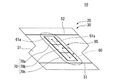
このシュラウド本体30の外周端面31には、図2〜図4に示すように、第一チップフィン51、第二チップフィン52及び凹部60が設けられている。
第一チップフィン51は、外周端面31における軸線O方向一方側に近接した箇所に設けられており、該外周端面31から径方向外側に突出し、外周端面31の周方向全域にわたって上流側端面41と平行に延びている。なお、第一チップフィン51の周方向の両端は、それぞれ第一傾斜面43a及び第四傾斜面44aに接続されている。
また、第二チップフィン52は、外周端面31における軸線O方向他方側に近接した箇所に設けられており、第一チップフィン51同様に該外周端面31から径方向外側に突出し、外周端面31の周方向全域にわたって下流側端面42と平行に延びている。なお。第二チップフィン52の周方向の両端は、それぞれ第三傾斜面43c及び第六傾斜面44cに接続されている。
このようにして、第一チップフィン51及び第二チップフィン52は、互いに軸線O方向に離間して平行に設けられている。これら第一チップフィン51及び第二チップフィン52によって、タービン動翼10とタービンケーシングとの間のシール性が確保される。
As shown in FIGS. 2 to 4, a
The
Further, the
In this way, the
凹部60は、外周端面31における上記第一チップフィン51と第二チップフィン52との間において、該外周端面31から径方向内側に凹んで径方向外側に開口するように形成されている。この凹部60は、外周端面31に沿う方向を長手方向として延在しており、本実施形態では、軸線O方向他方側に向かうに従って周方向他方側に向かう方向を長手方向として延在している。即ち、この凹部60は、翼本体11の上記断面形状の延在方向と同様、ロータ本体2本体の周方向及び軸線O方向にそれぞれ傾斜する方向を長手方向として延在している。この凹部60の長手方向の両端の縁部はそれぞれ円弧状をなしており、該凹部60の短手方向の両側の縁部は互いに平行に長手方向に延びる直線状をなしている。
The
そして、図2、図4及び図5に示すように、凹部60の底面62には、上記複数の冷却路14のうちの一部の冷却路14(本実施形態では6つの冷却路14のうちの3つ)の径方向外側の端部が開口している。これによって、凹部60とこれら一部の冷却路14とは連通状態とされている。
即ち、複数の冷却路14の径方向外側の端部は、翼本体11の上記断面形状の延在方向に対応してロータ本体2本体の周方向及び軸線O方向にそれぞれ傾斜する方向に配列されている。そして、これら冷却路14の端部の配列方向を長手方向として凹部60が延在するように形成されていることにより、凹部60内に一部の冷却路14の端部が開口している。
As shown in FIGS. 2, 4, and 5, the
That is, the radially outer ends of the plurality of
また、シュラウド本体30内には、該凹部60内と第一コンタクト面43の第三傾斜面43cとを連通する複数の冷却孔63(図2参照)が形成されているとともに、該凹部60内と第二コンタクト面44の第四傾斜面44aとを連通する複数の冷却孔63(図示省略)が形成されている。さらに、シュラウド本体30内には、凹部60内と第一コンタクト面43の第一傾斜面43aとを連通する複数の冷却孔64が形成されている。これら冷却孔63、64の第三傾斜面43c、第四傾斜面44a及び第一傾斜面43aにおける開口は、第三傾斜面43c、第四傾斜面44a及び第一傾斜面43aの延在方向に沿って配列されている。
A plurality of cooling holes 63 (see FIG. 2) are formed in the
ここで、外周端面31における第一チップフィン51よりも軸線O方向他方側に位置し、第一傾斜面43a及び第四傾斜面44aに接続される領域は、該外周端面31の第一主面32とされている。
また、外周端面31における凹部60の長手方向手前側(長手方向一端側、即ち、軸線O方向一方側かつ周方向一方側)の箇所は、第一主面32よりも一段径方向外側に平坦状に隆起した挿入面36とされている。
Here, the region of the outer
Further, a portion of the outer
そして、外周端面31における凹部60の長手方向手前側を除く縁部を含む領域は、該凹部60を短手方向両側及び長手方向奥側(軸線O方向他方側かつ周方向他方側)から囲うように第一主面32及び挿入面36よりも径方向外側に隆起した第二主面33とされている。したがって、凹部60は、外周端面31の第二主面33から径方向内側に凹むように形成されている。また、凹部60の長手方向手前側は、挿入面36側に開口している。
And the area | region including the edge part except the longitudinal direction front side of the recessed
外周端面31の第一主面32には、複数の冷却路14のうちの一部(本実施形態においては6つの冷却路14のうちの2つ)が開口している。また、外周端面31の第二主面33における凹部60の長手方向奥側の箇所には、複数の冷却路14のうちの一部(本実施形態においては6つの冷却路14のうちの1つ)が開口している。
Part of the plurality of cooling paths 14 (two of the six cooling
そして、図5に示すように、凹部60におけるその長手方向に沿う一対の側面61、即ち、該凹部60短手方向に対向する一対の側面61には、該長手方向に沿って延びる取付溝61aが形成されている。この取付溝61aは、一対の側面61からそれぞれ矩形に後退するように凹む溝であって、凹部60の長手方向全域にわたって延びている。
Then, as shown in FIG. 5, a pair of side surfaces 61 along the longitudinal direction of the
この取付溝61aの径方向位置は、挿入面36の径方向位置と略同一とされている。上述した凹部60の挿入面36側への開口は、後述するプラグ70を当該取付溝61aに挿入するためのプラグ挿入口65とされている。なお、プラグ挿入口65と第一チップフィン51との軸線O方向の間隔は、後述する第一プラグ片71及び第二プラグ片72がプラグ挿入口65に挿入可能となる分だけの寸法が確保されている。
The radial position of the mounting
プラグ70は、図3及び図6に示すように、複数のプラグ片から構成されており、本実施形態では2つの第一プラグ片71及び第二プラグ片72の二つのプラグ片から構成されている。
第一プラグ片71は、取付溝61aの径方向の溝幅と略同一の厚みを有する板状の部材であって、取付溝61aに挿入されることで、凹部60の開口における長手方向奥側の領域を閉塞可能とされている。
この第一プラグ片71が凹部60の開口における長手方向奥側の領域を閉塞するように取付溝61aに挿入された際の該第一プラグ片71の上記長手方向手前側を向く端面は、該長手方向奥側に向かうに従って凹部60の短手方向一方側に向かって傾斜する第一当接端面71aとされている。
なお、第一プラグ片71の上記長手方向奥側を向く端面は、凹部60の開口の形状に対応して円弧状をなしている。
As shown in FIGS. 3 and 6, the
The
When the
Note that the end surface of the
また、第二プラグ片72は、第一プラグ片71同様、取付溝61aの径方向の溝幅と略同一の厚みを有する板状の部材であって、凹部60の開口における長手方向手前側の領域を閉塞可能とされている。
この第二プラグ片72が凹部60の開口における長手方向手前側の領域を閉塞するように取付溝61aに挿入された際の該第二プラグ片72の上記長手方向奥側を向く端面は、該長手方向奥側に向かうに従って凹部60の短手方向一方側に向かって傾斜する第二当接端面72aとされている。
Similarly to the
When the
これら第一プラグ片71、第二プラグ片72は、取付溝61aに挿入された際に、並ぶようにして第一当接端面71a及び第二当接端面72aが互いに当接することにより、協働して凹部60の開口を閉塞する。このように、第一プラグ片71及び第二プラグ片72からなるプラグ70によって凹部60の開口が閉塞されることによって、図5に示すように、チップシュラウド20内には該チップシュラウド20外部と隔離された空間であるキャビティCが画成される。
When the
プラグ70によって凹部60の開口を閉塞する際には、図6(a)に示すように、まず第一プラグ片71をその先端側、即ち、端面が円弧状をなす側からプラグ挿入口65を介して取付溝61aに挿入する。これによって、第一プラグ片71の両側が取付溝61aにそれぞれ挟み込まれた状態となり、第一プラグ片71の径方向の移動が規制される。そして、この状態で第一プラグ片71を凹部60の長手方向奥側にスライドさせることで、凹部60の開口の長手方向奥側の領域に第一プラグ片71を配置させて、第一プラグ片71の先端を凹部60の長手方向奥側に当接させる。
When the opening of the
続いて、図6(b)に示すように、第二プラグ片72をその先端側、即ち、第二当接端面72a側からプラグ挿入口65を介して取付溝61aに挿入する。これによって、第二プラグ片72の両側が取付溝61aにそれぞれ挟み込まれた状態となり、第一プラグ片71の径方向の移動が規制される。そして、この状態で第二プラグ片72を凹部60の長手方向奥側にスライドさせることで、凹部60の開口の長手方向手前側の領域に第一プラグ片71を配置させて、第二当接端面72aを第一プラグ片71の第一当接端面71aに当接させる。
このように第一プラグ片71及び第二プラグ片72が取付溝61aに順次挿入されることで、凹部60の開口がその全域にわたって閉塞され、上記キャビティCが形成される。
Subsequently, as shown in FIG. 6B, the
As described above, the
以上のような構成のガスタービン動翼10を備えたガスタービン1においては、運転時に冷却空気が該翼本体11内の冷却路14に径方向内側から供給される。これによって、翼本体11が内部から冷却される。
また、各冷却路14の径方向外側の端部に到達した冷却空気は、チップシュラウド20内のキャビティCにて合流した後、冷却孔63を通ってチップシュラウド20の外部に放出される。このとき、冷却孔63の内面が冷却空気によって冷却されることで、チップシュラウド20がその内部から冷却される。
In the gas turbine 1 including the gas
The cooling air that has reached the radially outer end of each
ここで、ガスタービンの運転時には、ロータ本体2の回転に伴い遠心力が発生し、当該遠心力がチップシュラウド20のプラグ70にも作用する。これに対して本実施形態では、プラグ70を第一プラグ片71及び第二プラグ片72から構成し、これら第一プラグ片71及び第二プラグ片72のそれぞれを取付溝61aに挿入することにより凹部60の開口を閉塞したため、プラグ70を一枚物として構成した場合に比べて該プラグ70の破損を低減させることができる。したがって、プラグ70の耐久性を向上させることができ、長時間にわたってガスタービンの運転を継続させることができる。
Here, during operation of the gas turbine, a centrifugal force is generated as the
また、このようにプラグ70が分割されているため、プラグ挿入口65の軸線O方向側に第一チップフィン51及び第二チップフィン52がある場合であっても、容易に第一プラグ片71、第二プラグ片72を取付溝61aに挿入することができる。
Further, since the
さらに、本実施形態では、凹部60の長手方向に沿う一対の側面61に取付溝61aが形成されていることから、一対の側面61の対向方向は凹部60の短手方向となる。したがって、凹部60の短手方向に沿う側面に取付溝61aを形成した場合に比べて、一対の取付溝61aの間隔が狭く設定される。これにより、第一プラグ片71及び第二プラグ片72における取付溝61aの対向方向の間隔も狭く設定することができるため、遠心力による第一プラグ片71及び第二プラグ片72の変形を低減させることができる。
即ち、プラグ70がその長手方向全域にわたって取付溝61aに対して近接するように該プラグ70を配置することができるため、プラグ70の中央部が遠心力によって径方向外側に変形してしまうことを極力低減させることができる。
これによって、遠心力による第一プラグ片71及び第二プラグ片72の膨らみをより一層低減させることが可能となる。
Furthermore, in the present embodiment, since the mounting
That is, since the
As a result, the swelling of the
また、本実施形態では、凹部60の長手方向が軸線O方向から傾斜する方向に延在しているため、凹部60のプラグ挿入口65の軸線O方向側にチップフィンが設けられている場合であっても、当該チップフィンが妨げになることなく第一プラグ片71及び第二プラグ片72を容易に取付溝61aに挿入することができる。
さらに、凹部60の長手方向が周方向から傾斜する方向に延在しているため、ロータ本体2の周方向の回転加速度によって第一プラグ片71及び第二プラグ片72が取付溝61aから外れて凹部60が露呈してしまうことを防止できる。
Further, in the present embodiment, since the longitudinal direction of the
Furthermore, since the longitudinal direction of the
また、本実施形態では、側面61に取付溝61aを有する凹部60の長手方向手前側にプラグ挿入口65が形成されており、該プラグ挿入口65に取付溝61aと略同一の径方向位置の挿入面36が形成されているため、第一プラグ片71及び第二プラグ片72を容易に取付溝61aへと案内することができる。これによって、容易かつ確実に取付溝61aに第一プラグ片71及び第二プラグ片72を挿入することができる。
In the present embodiment, a
以上、本発明の実施形態について詳細に説明したが、本発明の技術的思想を逸脱しない限り、これらに限定されることはなく、多少の設計変更等も可能である。 As mentioned above, although embodiment of this invention was described in detail, unless it deviates from the technical idea of this invention, it is not limited to these, A some design change etc. are possible.
例えば実施形態では、シュラウド本体30における外周端面31が第一主面32、第二主面33を有するものとしたが、例えば図7の模式図に示す変形例のように、滑らかな外周端面31に凹部60が形成されたものであってもよい。
For example, in the embodiment, the outer
即ち、この変形例では、外周端面31における第一チップフィン51と第二チップフィン52との間の領域が、滑らかに湾曲する外周面状をなしており、当該外周端面31から径方向外側に凹むように凹部60が形成されている。そして、実施形態と同様に、取付溝61aに挿入される第一プラグ片71及び第二プラグ片72から構成されたプラグ70によって凹部60の開口が閉塞されるようになっている。これによっても、実施形態同様、プラグ70を第一プラグ片71及び第二プラグ片72に分割したことにより、遠心力によるプラグ70の膨らみを低減できる他、該プラグ70を容易に取付溝61aに挿入することができる。
In other words, in this modification, the region between the
また、実施形態では、プラグ70を第一プラグ片71及び第二プラグ片72から構成したが、図8に示す第二変形例として、プラグ70を3つのプラグ片70a,70b,70cから構成してもよい。この場合、各プラグ片70a,70b,70cの大きさがプラグ70を二分割した場合よりもさらに小さくなるため、遠心力による膨らみをより低減できるとともにより取付溝61aに挿入し易くなる。なお、プラグ70を4つ以上に分割してもよい。また、実施形態では取付溝61aは直線状に形成されていたが、第二変形例に示すように取付溝61aが曲線状に形成されていてもよい。
In the embodiment, the
さらに、例えば第三変形例として、図9に示すように、凹部60の長手方向に沿う一対の側面61のうちの一方における長手方向中央側に周方向他方側に向けて開口するプラグ挿入口65を設け、当該プラグ挿入口65から第一プラグ片71及び第二プラグ片72を取付溝61a内に挿入するようにしてもよい。この第三変形例では、プラグ挿入口65から挿入されたプラグ片70a,70cは、取付溝61aに沿って長手方向手前側、奥側に一枚ずつ移動される。その後、プラグ挿入口65にさらに一枚のプラグ片70cを挿入することで、計3枚のプラグ片70a,70b,70cによって凹部60の開口を閉塞することとしている。これによって、遠心力によるプラグ70の膨らみをより低減できるとともによりプラグ70を取付溝に挿入し易くすることができる。
Furthermore, as a third modification, for example, as shown in FIG. 9, a
また、実施形態では冷却について空気を使って行われるものとして説明したが、空気に限られるものではなく、例えば蒸気であってもよい。即ち、タービン動翼10に複数の冷却路14を設け、複数の冷却路14の一部には蒸気を翼根からロータ本体2の径方向外側に向けて流し、これをチップシュラウド20に設けられた凹部60とプラグ70とにより形成されたキャビティCに回収する。次に、回収された蒸気を、複数の冷却路14の残りを通じてロータ本体2の径方向内側に向けて流し、翼根側で回収する。この構成によれば、蒸気のような回収を要する冷却媒体を用いるタービン動翼10において、プラグ70の耐久性を向上することができる。
In the embodiment, the cooling has been described as being performed using air, but is not limited to air, and may be, for example, steam. That is, a plurality of
1 ガスタービン
2 ロータ本体
5 タービン
5a タービンケーシング
10 タービン動翼
11 翼本体
14 冷却路
20 チップシュラウド
30 シュラウド本体
31 外周端面
51 第一チップフィン(チップフィン)
52 第二チップフィン(チップフィン)
60 凹部
61 側面
61a 取付溝
62 底面
65 プラグ挿入口
70 プラグ
70a プラグ片
70b プラグ片
70c プラグ片
71 第一プラグ片(プラグ片)
71a 第一当接端面
72 第二プラグ片(第二プラグ片)
72a 第二当接端面
C キャビティ
DESCRIPTION OF SYMBOLS 1
52 Second chip fin (chip fin)
60 recess
61 side
61a Mounting groove
62 Bottom
65 Plug insertion slot
70 plug
70a plug piece
70b plug piece
71a First
72a Second contact end face C cavity
Claims (5)
前記翼本体内に前記径方向に延びて冷却媒体が流通する冷却路が形成され、
前記チップシュラウドは、
前記径方向外側に開口するように外周端面から凹んで前記冷却路の前記径方向外側の端部と連通する凹部が形成されるともに、該凹部の側面に取付溝が形成されたシュラウド本体と、
前記取付溝に順次挿入されることで互いに協働して前記凹部の開口を閉塞する複数のプラグ片を有するプラグとを備え、
前記凹部は、前記外周端面に沿う方向を長手方向として延在し、
前記取付溝は、前記長手方向に沿う一対の前記側面に形成され、
複数の前記プラグ片は、互いに当接するように前記長手方向に並んで前記凹部の開口を閉塞している
ことを特徴とするタービン動翼。 In a turbine rotor blade comprising a blade body attached to extend radially from a rotor body and a tip shroud fixed to the radially outer side of the blade body,
A cooling path that extends in the radial direction and through which the cooling medium flows is formed in the blade body,
The chip shroud is
A shroud main body having a recess recessed from an outer peripheral end surface so as to open to the radially outer side and communicating with the radially outer end of the cooling path, and a mounting groove formed on a side surface of the recess,
A plug having a plurality of plug pieces that are sequentially inserted into the mounting groove and cooperate with each other to close the opening of the recess ;
The concave portion extends in the direction along the outer peripheral end surface as a longitudinal direction,
The mounting groove is formed on the pair of side surfaces along the longitudinal direction,
The turbine blade according to claim 1, wherein the plurality of plug pieces are arranged in the longitudinal direction so as to abut against each other and close the openings of the recesses .
これら複数の冷却路の径方向外側の端部は、前記ロータ本体の周方向及び軸線O方向にそれぞれ傾斜する方向に配列されており、
前記凹部は、前記冷却路の径方向外側の端部の配列方向を前記長手方向として延在していることを特徴とする請求項1に記載のタービン動翼。 A plurality of the cooling paths are formed inside the blade body,
The radially outer ends of the plurality of cooling paths are arranged in directions inclined respectively in the circumferential direction and the axis O direction of the rotor body,
2. The turbine rotor blade according to claim 1 , wherein the concave portion extends with the arrangement direction of radially outer end portions of the cooling path as the longitudinal direction.
前記凹部の長手方向の少なくとも一端側に、前記プラグ片を前記取付溝に挿入するためのプラグ挿入口を有することを特徴とする請求項1又は2に記載のタービン動翼。 The shroud body is
The turbine rotor blade according to claim 1 or 2 , further comprising a plug insertion port for inserting the plug piece into the mounting groove on at least one end side in the longitudinal direction of the recess.
前記外周端面から突出して、前記ロータ本体の周方向に延びるとともに前記ロータ本体の軸線O方向に間隔をあけて配置された複数のチップフィンを有し、
前記凹部は、前記複数のチップフィンの間に形成されていることを特徴とする請求項1から3のいずれか一項に記載のタービン動翼。 The shroud body is
A plurality of chip fins protruding from the outer peripheral end surface, extending in the circumferential direction of the rotor body, and arranged at intervals in the axis O direction of the rotor body;
The turbine rotor blade according to any one of claims 1 to 3 , wherein the recess is formed between the plurality of tip fins.
該ロータ本体を回転可能に覆うケーシングと、
を備えていることを特徴とするガスタービン。 The rotor main body to which the turbine rotor blade according to any one of claims 1 to 4 is attached;
A casing that rotatably covers the rotor body;
A gas turbine comprising:
Priority Applications (6)
| Application Number | Priority Date | Filing Date | Title |
|---|---|---|---|
| JP2011236148A JP5881369B2 (en) | 2011-10-27 | 2011-10-27 | Turbine blade and gas turbine provided with the same |
| PCT/JP2012/077455 WO2013061997A1 (en) | 2011-10-27 | 2012-10-24 | Turbine blade, and gas turbine including same |
| KR1020147000124A KR101551132B1 (en) | 2011-10-27 | 2012-10-24 | Turbine blade, and gas turbine including same |
| EP12844208.4A EP2752555B1 (en) | 2011-10-27 | 2012-10-24 | Turbine blade, and gas turbine including same |
| CN201280036830.9A CN103703216B (en) | 2011-10-27 | 2012-10-24 | Turbine moving blade and possess the gas turbine of this turbine moving blade |
| US13/660,431 US9371741B2 (en) | 2011-10-27 | 2012-10-25 | Turbine blade and gas turbine having the same |
Applications Claiming Priority (1)
| Application Number | Priority Date | Filing Date | Title |
|---|---|---|---|
| JP2011236148A JP5881369B2 (en) | 2011-10-27 | 2011-10-27 | Turbine blade and gas turbine provided with the same |
Publications (2)
| Publication Number | Publication Date |
|---|---|
| JP2013092138A JP2013092138A (en) | 2013-05-16 |
| JP5881369B2 true JP5881369B2 (en) | 2016-03-09 |
Family
ID=48167824
Family Applications (1)
| Application Number | Title | Priority Date | Filing Date |
|---|---|---|---|
| JP2011236148A Active JP5881369B2 (en) | 2011-10-27 | 2011-10-27 | Turbine blade and gas turbine provided with the same |
Country Status (6)
| Country | Link |
|---|---|
| US (1) | US9371741B2 (en) |
| EP (1) | EP2752555B1 (en) |
| JP (1) | JP5881369B2 (en) |
| KR (1) | KR101551132B1 (en) |
| CN (1) | CN103703216B (en) |
| WO (1) | WO2013061997A1 (en) |
Families Citing this family (9)
| Publication number | Priority date | Publication date | Assignee | Title |
|---|---|---|---|---|
| US10202852B2 (en) * | 2015-11-16 | 2019-02-12 | General Electric Company | Rotor blade with tip shroud cooling passages and method of making same |
| US11092039B2 (en) * | 2016-10-27 | 2021-08-17 | General Electric Company | Apparatus for circumferential separation of turbine blades |
| US10494932B2 (en) * | 2017-02-07 | 2019-12-03 | General Electric Company | Turbomachine rotor blade cooling passage |
| US11060407B2 (en) * | 2017-06-22 | 2021-07-13 | General Electric Company | Turbomachine rotor blade |
| EP3696425B1 (en) * | 2017-10-11 | 2023-05-03 | Mitsubishi Heavy Industries Engine & Turbocharger, Ltd. | Impeller for centrifugal rotating machine, and centrifugal rotating machine |
| JP7064076B2 (en) * | 2018-03-27 | 2022-05-10 | 三菱重工業株式会社 | How to tune turbine blades, turbines, and natural frequencies of turbine blades |
| US11143286B2 (en) * | 2019-03-15 | 2021-10-12 | Hamilton Sundstrand Corporation | Differential unit gear shrouds |
| KR102120417B1 (en) * | 2020-05-27 | 2020-06-08 | 두산중공업 주식회사 | Turbine blade, turbine and gas turbine comprising the same |
| CN114211438B (en) * | 2021-12-14 | 2023-08-18 | 东方电气集团东方汽轮机有限公司 | Transverse stationary blade assembling method and positioning tool |
Family Cites Families (14)
| Publication number | Priority date | Publication date | Assignee | Title |
|---|---|---|---|---|
| CH580750A5 (en) * | 1974-07-17 | 1976-10-15 | Bbc Sulzer Turbomaschinen | |
| CH582305A5 (en) * | 1974-09-05 | 1976-11-30 | Bbc Sulzer Turbomaschinen | |
| US4073599A (en) * | 1976-08-26 | 1978-02-14 | Westinghouse Electric Corporation | Hollow turbine blade tip closure |
| JPH03194101A (en) * | 1989-12-21 | 1991-08-23 | Toshiba Corp | Gas turbine cooling moving blade |
| JP3510467B2 (en) | 1998-01-13 | 2004-03-29 | 三菱重工業株式会社 | Gas turbine blades |
| JP3403051B2 (en) * | 1998-02-04 | 2003-05-06 | 三菱重工業株式会社 | Gas turbine blade |
| US6019572A (en) * | 1998-08-06 | 2000-02-01 | Siemens Westinghouse Power Corporation | Gas turbine row #1 steam cooled vane |
| EP1041247B1 (en) | 1999-04-01 | 2012-08-01 | General Electric Company | Gas turbine airfoil comprising an open cooling circuit |
| US6761534B1 (en) * | 1999-04-05 | 2004-07-13 | General Electric Company | Cooling circuit for a gas turbine bucket and tip shroud |
| JP2003065068A (en) | 2001-08-29 | 2003-03-05 | Mitsubishi Heavy Ind Ltd | Method for closing used hole on top of gas turbine blade |
| US6942450B2 (en) * | 2003-08-22 | 2005-09-13 | Siemens Westinghouse Power Corporation | Differential pressure sensing system for airfoils usable in turbine engines |
| US7625172B2 (en) * | 2006-04-26 | 2009-12-01 | United Technologies Corporation | Vane platform cooling |
| US7946816B2 (en) * | 2008-01-10 | 2011-05-24 | General Electric Company | Turbine blade tip shroud |
| US8322986B2 (en) * | 2008-07-29 | 2012-12-04 | General Electric Company | Rotor blade and method of fabricating the same |
-
2011
- 2011-10-27 JP JP2011236148A patent/JP5881369B2/en active Active
-
2012
- 2012-10-24 CN CN201280036830.9A patent/CN103703216B/en active Active
- 2012-10-24 KR KR1020147000124A patent/KR101551132B1/en active IP Right Grant
- 2012-10-24 WO PCT/JP2012/077455 patent/WO2013061997A1/en active Application Filing
- 2012-10-24 EP EP12844208.4A patent/EP2752555B1/en active Active
- 2012-10-25 US US13/660,431 patent/US9371741B2/en active Active
Also Published As
| Publication number | Publication date |
|---|---|
| WO2013061997A1 (en) | 2013-05-02 |
| JP2013092138A (en) | 2013-05-16 |
| KR101551132B1 (en) | 2015-09-07 |
| US20130142667A1 (en) | 2013-06-06 |
| EP2752555B1 (en) | 2019-06-19 |
| KR20140029513A (en) | 2014-03-10 |
| CN103703216A (en) | 2014-04-02 |
| US9371741B2 (en) | 2016-06-21 |
| CN103703216B (en) | 2015-09-30 |
| EP2752555A4 (en) | 2015-05-06 |
| EP2752555A1 (en) | 2014-07-09 |
Similar Documents
| Publication | Publication Date | Title |
|---|---|---|
| JP5881369B2 (en) | Turbine blade and gas turbine provided with the same | |
| EP2990608B1 (en) | Rotor blade and gas turbine equipped with same | |
| EP3392462B1 (en) | Insert assembly, blade, gas turbine, and blade manufacturing method | |
| JP6496542B2 (en) | Structural configuration and cooling circuit in turbine blade | |
| JP5017064B2 (en) | Trifolia tip cavity airfoil | |
| JP6344869B2 (en) | Turbine vane, turbine, and method for modifying turbine vane | |
| EP2758634B1 (en) | Impingement cooling of turbine blades or vanes | |
| JP4902157B2 (en) | Turbine blade with a groove at the tip | |
| JP5442190B2 (en) | Similar tip baffle airfoil | |
| JP6739934B2 (en) | Gas turbine seals | |
| JP2017120077A (en) | Midspan shrouded turbine rotor blades | |
| JP2005337258A (en) | Rotor blade | |
| EP3184743B1 (en) | Turbine airfoil with trailing edge cooling circuit | |
| KR20110108418A (en) | Turbine blade and gas turbine | |
| JP6435188B2 (en) | Structural configuration and cooling circuit in turbine blades | |
| ES2897722T3 (en) | Turbine mounting for impact cooling and mounting method | |
| KR20220155187A (en) | Gas turbine inner shroud with array of protuberances | |
| US9739155B2 (en) | Structural configurations and cooling circuits in turbine blades | |
| JP5524137B2 (en) | Gas turbine blade | |
| CN111058899A (en) | Rotor assembly with rotor disk lip | |
| JP6521273B2 (en) | Steam turbine | |
| WO2018020548A1 (en) | Seal structure for gas turbine rotor blade | |
| JP5669769B2 (en) | Gas turbine sealing device | |
| US20150104320A1 (en) | Turbine with bucket fixing means | |
| JP4284643B2 (en) | Turbine nozzle cooling structure of gas turbine |
Legal Events
| Date | Code | Title | Description |
|---|---|---|---|
| A621 | Written request for application examination |
Free format text: JAPANESE INTERMEDIATE CODE: A621 Effective date: 20140717 |
|
| A131 | Notification of reasons for refusal |
Free format text: JAPANESE INTERMEDIATE CODE: A131 Effective date: 20150407 |
|
| A521 | Request for written amendment filed |
Free format text: JAPANESE INTERMEDIATE CODE: A523 Effective date: 20150608 |
|
| A521 | Request for written amendment filed |
Free format text: JAPANESE INTERMEDIATE CODE: A821 Effective date: 20150609 |
|
| TRDD | Decision of grant or rejection written | ||
| A01 | Written decision to grant a patent or to grant a registration (utility model) |
Free format text: JAPANESE INTERMEDIATE CODE: A01 Effective date: 20160105 |
|
| A61 | First payment of annual fees (during grant procedure) |
Free format text: JAPANESE INTERMEDIATE CODE: A61 Effective date: 20160202 |
|
| R151 | Written notification of patent or utility model registration |
Ref document number: 5881369 Country of ref document: JP Free format text: JAPANESE INTERMEDIATE CODE: R151 |