JP4284643B2 - Turbine nozzle cooling structure of gas turbine - Google Patents
Turbine nozzle cooling structure of gas turbine Download PDFInfo
- Publication number
- JP4284643B2 JP4284643B2 JP2003111383A JP2003111383A JP4284643B2 JP 4284643 B2 JP4284643 B2 JP 4284643B2 JP 2003111383 A JP2003111383 A JP 2003111383A JP 2003111383 A JP2003111383 A JP 2003111383A JP 4284643 B2 JP4284643 B2 JP 4284643B2
- Authority
- JP
- Japan
- Prior art keywords
- turbine
- nozzle
- combustor
- turbine nozzle
- cooling
- Prior art date
- Legal status (The legal status is an assumption and is not a legal conclusion. Google has not performed a legal analysis and makes no representation as to the accuracy of the status listed.)
- Expired - Lifetime
Links
Images


Landscapes
- Turbine Rotor Nozzle Sealing (AREA)
Description
【0001】
【発明の属する技術分野】
本発明は、ガスタービンのタービンノズル冷却構造に関する。
【0002】
【従来の技術】
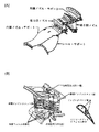
タービンノズルは、[非特許文献1]の図4(A)に記載されているように、ノズルガイドベーン(静翼)を環状に並べたもので、ベーンとその支持構造物とからなる。また、図4(B)に示す空冷式タービンベーンが知られている。
また、タービンノズルの冷却に関して、例えば[非特許文献2]に記載されている。
【0003】
【非特許文献1】
新航空工学講座8、ジェットエンジン(構造編)、社団法人日本航空技術協会
【非特許文献2】
武石賢一郎、タービンにおける損失発生のメカニズムと熱力学的考察、Proceedings of the TED-COF.'01,JSME
【0004】
タービンノズルは、燃焼器からの高温ガスを加速して下流側のタービンに導入する機能を有する。そのため、タービンノズルは、エンジン流路の高温ガスにさらされるため、冷却が不可欠である。
【0005】
この要望を満たすために、例えば[特許文献1]の「ガスタービンタービン冷却静翼」が提案されている。
【0006】
【特許文献1】
特開2001−254604号公報
【0007】
[特許文献1]の「ガスタービンタービン冷却静翼」は、図5に示すように、1段静翼120の外側シュラウド121の外側、内側シュラウドの内側壁面には格子状のワッフルパターン101が形成され、強度を向上させ、1段静翼120の後縁最後列の冷却穴を他の穴径より大きい拡大冷却穴106とし後縁の冷却効率を高め、壁内側にリブ102を形成し、薄肉化を計る。内側シュラウド122の背側、腹側両側端内部には冷却通路103を設け、更に内側から貫通し表面端部へ開口する複数の冷却穴105を設けることによりシュラウドの冷却効果を高める。これらの改良により、翼後縁部やシュラウドのクラック発生や変形を防止するものである。
【0008】
【発明が解決しようとする課題】
上述したように、タービン入口温度の高い従来のガスタービンでは、タービンノズル(1段静翼)の内側シュラウド(「バンド部」ともいう)の冷却が不可欠であり、バンド部を二重板構造として内部に冷却空気を通し、冷却していた。
【0009】
しかし、バンド部冷却のための2枚板構造により、構造が複雑となりコストが上昇するだけでなく信頼性が低下する要因となり、かつ重量が増加するためエンジン性能が低下する問題点があった。
【0010】
本発明は、上述した問題点を解決するために創案されたものである。すなわち、本発明の目的は、タービン入口温度の高いガスタービンにおいて、バンド部を二重板構造とすることなく、バンド部を効果的に冷却することができ、これにより、構造の単純化によりコストダウンと信頼性の向上を達成し、かつ軽量化によりエンジン性能を向上することができるガスタービンのタービンノズル冷却構造を提供することにある。
【0011】
本発明によれば、燃焼器とタービン動翼との間に位置し燃焼器からの高温ガスを下流側のタービンに導入するタービンノズルと、該タービンノズルの前端部と燃焼器との間をシールするシールプレートとを備え、前記シールプレートは、前記高温ガスの下流側から上流側の方向を向く側面を有し、前記燃焼器は、前記高温ガスの上流側から下流側へ延びることで前記シールプレートの前記側面に接触するフランジ部を有し、該フランジ部に内外面を連通する複数の切欠き溝が設けられ、該各切欠き溝と前記シールプレートの前記側面とにより流路孔が形成され、該流路孔を通して冷却空気が流入しタービンノズルのバンド表面に沿って流れその表面をフィルム冷却する、ことを特徴とするガスタービンのタービンノズル冷却構造が提供される。
【0012】
上記本発明の構成によれば、シールプレートに接触する燃焼器のフランジ部に内外面を連通する複数の切欠き溝が設けられているので、この切欠き溝を通して外側から冷却空気が流入しタービンノズルのバンド表面に沿って流れその表面をフィルム冷却することができる。
従って、タービン入口温度の高いガスタービンにおいて、バンド部を二重板構造とすることなく、バンド部を効果的に冷却することができ、これにより、構造の単純化によりコストダウンと信頼性の向上を達成し、かつ軽量化によりエンジン性能を向上することができる。
【0013】
【発明の実施の形態】
以下、本発明の好ましい実施形態を図面を参照して説明する。なお、各図において、共通する部分には同一の符号を付し、重複した説明を省略する。
【0014】
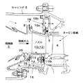
図1は、本発明の冷却構造によるタービンノズル部の全体断面図である。この図に示すように、本発明のタービンノズル冷却構造は、燃焼器2、およびタービンノズル10を備える。
【0015】
タービンノズル10は、燃焼器2とタービン動翼4との間に位置し、燃焼器2からの高温ガスを下流側のタービンに導入する機能を有する。
【0016】
図1において、本発明のタービンノズル冷却構造は、更にノズルサポート部材14、およびストッパー部材16を備える。
ノズルサポート部材14は、タービンノズル10の内側に固定されたエンジン中心を中心とする回転体であり、その周囲にタービンノズル10を嵌め込むための半径方向に延びる溝部14aを有する。また、この溝部14aを挟む前後のフランジ部には、周方向に一定の間隔を隔てて複数の軸方向貫通孔14bが設けられている。
【0017】
ストッパー部材16は、タービンノズル10の外側に位置し、外方端がエンジンのケーシング6に固定されている。
【0018】
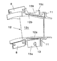
図2は、本発明を構成するノズルセグメントの斜視図である。この図に示すように、タービンノズル10は、周方向に分割された複数のノズルセグメント12からなる。各ノズルセグメント12の周方向端面は、隣接する各ノズルセグメント12の端面に密接し、端面に設けられた溝11に嵌め込むシールプレート(図示せず)により、その間がシールされる。
【0019】
ノズルセグメント12は、内側シュラウド12a、外側シュラウド12b、および翼部12cからなる。内側シュラウド12aと外側シュラウド12bは、本発明においてそれぞれ内側バンド部、外側バンド部とも呼ぶ。
【0020】
ノズルセグメント12は、その内側シュラウド12a(内側バンド部)から半径方向内方に張出した内側フランジ15aと、その外側シュラウド12b(外側バンド部)から半径方向外方に張出した外側フランジ15bとを有する。外側フランジ15bは、ノズルサポート部材14の溝部14aに嵌め込まれ、前後方向に移動しないようになっている。
【0021】
また、内側フランジ15aには単一の軸方向貫通孔13が設けられ、取付ピン18が軸方向貫通孔13をノズルサポート部材14の溝部14aと共に貫通することによりノズルセグメント12がノズルサポート部材14に取付けられる。
【0022】
図1において、ストッパー部材16は、エンジン中心を中心とするリング状部材である。またその外周縁の複数箇所にケーシング6との周方向位置決めのための嵌合部16bを有する。この嵌合部16bは軸方向に突出した矩形部材であり、ケーシング6に設けられた凹部と嵌合することにより、ストッパー部材16を周方向に位置決めしている。
また、ストッパー部材16は、内周縁に段差が設けられ、かつ内周縁に沿って周方向に設けられた複数の凹部16aを有する。この凹部16aは、分割された複数の各ノズルセグメント12毎に1つずつ対応する箇所に設けられている。
【0023】
図1において、本発明のタービンノズル冷却構造では、更に、ノズルセグメント12の前端部と燃焼器2との間をシールするシールプレート8と、ノズルセグメント12の後端部とケーシング6との間をシールするEシール9とを備え、ノズルセグメント12の前後をシールすることにより、ノズルの内側と外側間のシール性能を保持するようになっている。
【0024】
図3は、図1のA-A矢視図である。この図に示すように、本発明では、シールプレート8に接触する燃焼器2のフランジ部2aに内外面を連通する複数の切欠き溝20が設けられる。この切欠き溝20は、この溝を通して燃焼器2の外側から冷却空気が流入し、タービンノズル12の内側シュラウド12a(内側バンド部)のバンド表面に沿って流れ、その表面をフィルム冷却するようになっている。
【0025】
切欠き溝20の断面形状と向きは任意であり、半円形又は矩形であり、半径方向または斜めであってもよい。また切欠き溝20の大きさは、内側バンド部のバンド表面に沿って流れるフィルム冷却膜を形成し、内側バンド部の過熱を防ぐ限りで十分に小さく、主流ガスのタービン入口温度に影響しないように設定する。
【0026】
上記本発明の構成によれば、シールプレート(8)に接触する燃焼器(2)のフランジ部に内外面を連通する複数の切欠き溝(20)が設けられているので、この切欠き溝を通して外側から冷却空気が流入しタービンノズルのバンド表面に沿って流れその表面をフィルム冷却することができる。
従って、タービン入口温度の高いガスタービンにおいて、バンド部を二重板構造とすることなく、バンド部を効果的に冷却することができ、これにより、構造の単純化によりコストダウンと信頼性の向上を達成し、かつ軽量化によりエンジン性能を向上することができる。
【0027】
なお、本発明は上述した実施例に限定されず、本発明の要旨を逸脱しない限りで自由に変更することができることは勿論である。例えば、本発明を航空用、舶用、陸上用のガスタービンに広く適用することができる。
【0028】
【発明の効果】
上述した本発明により、静翼自体のバンド部冷却構造が不要となり、以下の効果が期待できる。
(1)構造の単純化による信頼性向上
(2)構造の単純化によるコストダウン
(3)軽量化によるエンジン性能向上
【0029】
従って、本発明のタービンノズル冷却構造は、タービン入口温度の高いガスタービンにおいて、バンド部を二重板構造とすることなく、バンド部を効果的に冷却することができ、これにより、構造の単純化によりコストダウンと信頼性の向上を達成し、かつ軽量化によりエンジン性能を向上することができる、等の優れた効果を有する。
【図面の簡単な説明】
【図1】本発明の冷却構造によるタービンノズル部の全体断面図である。
【図2】本発明を構成するノズルセグメントの斜視図である。
【図3】図1のA-A矢視図である。
【図4】従来のタービンノズル構造の斜視図である。
【図5】従来のタービンノズル冷却構造の例を示す全体断面図である。
【符号の説明】
2 燃焼器、2a フランジ部、4 タービン動翼、
6 ケーシング、8 シールプレート、9 Eシール、
10 タービンノズル、12 ノズルセグメント、
12a 内側シュラウド(内側バンド部)、
12b 外側シュラウド(外側バンド部)、
12c 翼部、13 貫通孔、
14 ノズルサポート部材、15a 内側フランジ、
15b 外側フランジ、15c タブ、
16 ストッパー部材、
16a 凹部、16b 嵌合部、
18 取付ピン、20 切欠き溝[0001]
BACKGROUND OF THE INVENTION
The present invention relates to a turbine nozzle cooling structure for a gas turbine.
[0002]
[Prior art]
As described in FIG. 4A of [Non-Patent Document 1], the turbine nozzle is configured by arranging nozzle guide vanes (static blades) in an annular shape, and includes a vane and a support structure thereof. Further, an air-cooled turbine vane shown in FIG. 4B is known.
Further, the cooling of the turbine nozzle is described in, for example, [Non-Patent Document 2].
[0003]
[Non-Patent Document 1]
New Aeronautical Engineering
Kenichiro Takeishi, Mechanism of loss generation in turbines and thermodynamic considerations, Proceedings of the TED-COF. '01, JSME
[0004]
The turbine nozzle has a function of accelerating the hot gas from the combustor and introducing it into the downstream turbine. Therefore, since the turbine nozzle is exposed to the hot gas in the engine flow path, cooling is indispensable.
[0005]
In order to satisfy this demand, for example, a “gas turbine turbine cooling stationary blade” of [Patent Document 1] has been proposed.
[0006]
[Patent Document 1]
Japanese Patent Laid-Open No. 2001-254604
As shown in FIG. 5, the “gas turbine turbine cooling stator blade” of [Patent Document 1] has a lattice-
[0008]
[Problems to be solved by the invention]
As described above, in a conventional gas turbine having a high turbine inlet temperature, it is indispensable to cool the inner shroud (also referred to as “band part”) of the turbine nozzle (first stage stationary blade), and the band part is formed as a double plate structure inside. Cooling air was passed through to cool.
[0009]
However, the two-plate structure for cooling the band part has a problem that the structure is complicated and the cost is increased and the reliability is lowered, and the engine performance is lowered due to an increase in weight.
[0010]
The present invention has been developed to solve the above-described problems. That is, the object of the present invention is to effectively cool the band portion without using a double plate structure in the gas turbine having a high turbine inlet temperature, thereby reducing the cost by simplifying the structure. An object of the present invention is to provide a turbine nozzle cooling structure for a gas turbine that can achieve downs and improved reliability, and can improve engine performance through weight reduction.
[0011]
According to the present invention, a turbine nozzle that is located between the combustor and the turbine blade and introduces the hot gas from the combustor to the turbine on the downstream side, and a seal between the front end of the turbine nozzle and the combustor is sealed. The seal plate has a side surface facing from the downstream side to the upstream side of the hot gas, and the combustor extends from the upstream side to the downstream side of the hot gas, thereby the seal plate. A flange portion that contacts the side surface of the plate, and a plurality of notch grooves that communicate with the inner and outer surfaces are provided in the flange portion, and a flow path hole is formed by each notch groove and the side surface of the seal plate is, the cooling air through the flow channel hole film cooling flow the surface along the inflow band surface of the turbine nozzle, a turbine nozzle cooling structure of a gas turbine is provided, wherein
[0012]
According to the configuration of the present invention described above, since the plurality of notch grooves communicating the inner and outer surfaces are provided in the flange portion of the combustor that contacts the seal plate, the cooling air flows from the outside through the notch grooves, and the turbine It can flow along the nozzle band surface and film cool the surface.
Therefore, in a gas turbine having a high turbine inlet temperature, the band portion can be effectively cooled without using a double plate structure, thereby reducing costs and improving reliability by simplifying the structure. The engine performance can be improved by reducing the weight.
[0013]
DETAILED DESCRIPTION OF THE INVENTION
Hereinafter, preferred embodiments of the present invention will be described with reference to the drawings. In each figure, common portions are denoted by the same reference numerals, and redundant description is omitted.
[0014]
FIG. 1 is an overall cross-sectional view of a turbine nozzle portion according to the cooling structure of the present invention. As shown in this figure, the turbine nozzle cooling structure of the present invention includes a
[0015]
The
[0016]
In FIG. 1, the turbine nozzle cooling structure of the present invention further includes a
The
[0017]
The
[0018]
FIG. 2 is a perspective view of a nozzle segment constituting the present invention. As shown in this figure, the
[0019]
The
[0020]
The
[0021]
The
[0022]
In FIG. 1, the
The
[0023]
In FIG. 1, in the turbine nozzle cooling structure of the present invention, a
[0024]
FIG. 3 is an AA arrow view of FIG. As shown in this figure, in the present invention, a plurality of
[0025]
The cross-sectional shape and direction of the
[0026]
According to the configuration of the present invention, since the plurality of notch grooves (20) communicating the inner and outer surfaces are provided in the flange portion of the combustor (2) that contacts the seal plate (8), the notch grooves are provided. Through which the cooling air flows from the outside and flows along the band surface of the turbine nozzle, and the surface can be film-cooled.
Therefore, in a gas turbine having a high turbine inlet temperature, the band portion can be effectively cooled without using a double plate structure, thereby reducing costs and improving reliability by simplifying the structure. The engine performance can be improved by reducing the weight.
[0027]
In addition, this invention is not limited to the Example mentioned above, Of course, it can change freely, unless it deviates from the summary of this invention. For example, the present invention can be widely applied to aviation, marine, and onshore gas turbines.
[0028]
【The invention's effect】
According to the present invention described above, the band cooling structure of the stationary blade itself becomes unnecessary, and the following effects can be expected.
(1) Improving reliability by simplifying the structure (2) Cost reduction by simplifying the structure (3) Improving engine performance by reducing weight [0029]
Therefore, the turbine nozzle cooling structure according to the present invention can effectively cool the band part in a gas turbine having a high turbine inlet temperature without using a double plate structure for the band part. It has excellent effects such as reducing costs and improving reliability by making it easier, and improving engine performance by making it lighter.
[Brief description of the drawings]
FIG. 1 is an overall cross-sectional view of a turbine nozzle portion according to a cooling structure of the present invention.
FIG. 2 is a perspective view of a nozzle segment constituting the present invention.
FIG. 3 is a view taken along the line AA in FIG. 1;
FIG. 4 is a perspective view of a conventional turbine nozzle structure.
FIG. 5 is an overall cross-sectional view showing an example of a conventional turbine nozzle cooling structure.
[Explanation of symbols]
2 combustor, 2a flange, 4 turbine blade,
6 Casing, 8 Seal plate, 9 E seal,
10 turbine nozzles, 12 nozzle segments,
12a inner shroud (inner band part),
12b outer shroud (outer band part),
12c wing, 13 through hole,
14 Nozzle support member, 15a Inner flange,
15b outer flange, 15c tab,
16 stopper member,
16a recessed part, 16b fitting part,
18 Mounting pin, 20 Notch groove
Claims (1)
前記シールプレートは、前記高温ガスの下流側から上流側の方向を向く側面を有し、前記燃焼器は、前記高温ガスの上流側から下流側へ延びることで前記シールプレートの前記側面に接触するフランジ部を有し、該フランジ部に内外面を連通する複数の切欠き溝が設けられ、
該各切欠き溝と前記シールプレートの前記側面とにより流路孔が形成され、該流路孔を通して冷却空気が流入しタービンノズルのバンド表面に沿って流れその表面をフィルム冷却する、ことを特徴とするガスタービンのタービンノズル冷却構造。A turbine nozzle located between the combustor and the turbine rotor blade for introducing a hot gas from the combustor to a downstream turbine; and a seal plate for sealing between the front end of the turbine nozzle and the combustor. ,
The seal plate has a side surface facing from the downstream side to the upstream side of the hot gas, and the combustor contacts the side surface of the seal plate by extending from the upstream side to the downstream side of the hot gas. A plurality of notch grooves having a flange portion and communicating the inner and outer surfaces are provided in the flange portion,
A flow path hole is formed by each notch groove and the side surface of the seal plate, cooling air flows through the flow path hole , flows along the band surface of the turbine nozzle, and the surface is film-cooled. Gas turbine turbine nozzle cooling structure.
Priority Applications (1)
| Application Number | Priority Date | Filing Date | Title |
|---|---|---|---|
| JP2003111383A JP4284643B2 (en) | 2003-04-16 | 2003-04-16 | Turbine nozzle cooling structure of gas turbine |
Applications Claiming Priority (1)
| Application Number | Priority Date | Filing Date | Title |
|---|---|---|---|
| JP2003111383A JP4284643B2 (en) | 2003-04-16 | 2003-04-16 | Turbine nozzle cooling structure of gas turbine |
Publications (2)
| Publication Number | Publication Date |
|---|---|
| JP2004316542A JP2004316542A (en) | 2004-11-11 |
| JP4284643B2 true JP4284643B2 (en) | 2009-06-24 |
Family
ID=33471950
Family Applications (1)
| Application Number | Title | Priority Date | Filing Date |
|---|---|---|---|
| JP2003111383A Expired - Lifetime JP4284643B2 (en) | 2003-04-16 | 2003-04-16 | Turbine nozzle cooling structure of gas turbine |
Country Status (1)
| Country | Link |
|---|---|
| JP (1) | JP4284643B2 (en) |
Families Citing this family (4)
| Publication number | Priority date | Publication date | Assignee | Title |
|---|---|---|---|---|
| US20090169369A1 (en) * | 2007-12-29 | 2009-07-02 | General Electric Company | Turbine nozzle segment and assembly |
| US9541006B2 (en) | 2012-12-29 | 2017-01-10 | United Technologies Corporation | Inter-module flow discourager |
| JP6271582B2 (en) * | 2012-12-29 | 2018-01-31 | ユナイテッド テクノロジーズ コーポレイションUnited Technologies Corporation | Gas turbine seal assembly and seal support |
| US9845695B2 (en) | 2012-12-29 | 2017-12-19 | United Technologies Corporation | Gas turbine seal assembly and seal support |
-
2003
- 2003-04-16 JP JP2003111383A patent/JP4284643B2/en not_active Expired - Lifetime
Also Published As
| Publication number | Publication date |
|---|---|
| JP2004316542A (en) | 2004-11-11 |
Similar Documents
| Publication | Publication Date | Title |
|---|---|---|
| US7008185B2 (en) | Gas turbine engine turbine nozzle bifurcated impingement baffle | |
| US6932568B2 (en) | Turbine nozzle segment cantilevered mount | |
| JP4130321B2 (en) | Gas turbine engine components | |
| US8740551B2 (en) | Blade outer air seal cooling | |
| US6969233B2 (en) | Gas turbine engine turbine nozzle segment with a single hollow vane having a bifurcated cavity | |
| EP0926314B1 (en) | Seal structure for gas turbines | |
| US9551224B2 (en) | Turbine and method for manufacturing turbine | |
| TWI632289B (en) | Blade and gas turbine provided with the same | |
| JP2007120501A (en) | Interstage seal, turbine blade, and interface seal between cooled rotor and stator of gas turbine engine | |
| JP2006342797A (en) | Seal assembly of gas turbine engine, rotor assembly, blade for rotor assembly and inter-stage cavity seal | |
| US20100316486A1 (en) | Cooled component for a gas turbine engine | |
| EP3012405B1 (en) | Gas turbine engine with coolant flow redirection component | |
| US20180142564A1 (en) | Combined turbine nozzle and shroud deflection limiter | |
| JP4284643B2 (en) | Turbine nozzle cooling structure of gas turbine | |
| EP3673153B1 (en) | Rim seal arrangement | |
| JP5770970B2 (en) | Turbine nozzle for gas turbine engine | |
| JP4909113B2 (en) | Steam turbine casing structure | |
| JP6638594B2 (en) | Supercharger | |
| JP2004169655A (en) | Turbine nozzle supporting structure | |
| JP2600955B2 (en) | Double-flow steam turbine | |
| JP2021071085A (en) | Turbine blade and gas turbine equipped with the same | |
| JPH09329003A (en) | Turbine shroud attached with a gas sealing device | |
| JP2008144624A (en) | Turbine moving blade fixing structure | |
| WO2024106093A1 (en) | Shroud cooling structure for turbine stationary blade, and method for producing same | |
| CA2713284C (en) | Blade outer air seal cooling |
Legal Events
| Date | Code | Title | Description |
|---|---|---|---|
| A621 | Written request for application examination |
Free format text: JAPANESE INTERMEDIATE CODE: A621 Effective date: 20060328 |
|
| A977 | Report on retrieval |
Free format text: JAPANESE INTERMEDIATE CODE: A971007 Effective date: 20081010 |
|
| A131 | Notification of reasons for refusal |
Free format text: JAPANESE INTERMEDIATE CODE: A131 Effective date: 20081016 |
|
| A521 | Request for written amendment filed |
Free format text: JAPANESE INTERMEDIATE CODE: A523 Effective date: 20081212 |
|
| TRDD | Decision of grant or rejection written | ||
| A01 | Written decision to grant a patent or to grant a registration (utility model) |
Free format text: JAPANESE INTERMEDIATE CODE: A01 Effective date: 20090227 |
|
| A01 | Written decision to grant a patent or to grant a registration (utility model) |
Free format text: JAPANESE INTERMEDIATE CODE: A01 |
|
| A61 | First payment of annual fees (during grant procedure) |
Free format text: JAPANESE INTERMEDIATE CODE: A61 Effective date: 20090312 |
|
| FPAY | Renewal fee payment (event date is renewal date of database) |
Free format text: PAYMENT UNTIL: 20120403 Year of fee payment: 3 |
|
| R151 | Written notification of patent or utility model registration |
Ref document number: 4284643 Country of ref document: JP Free format text: JAPANESE INTERMEDIATE CODE: R151 |
|
| FPAY | Renewal fee payment (event date is renewal date of database) |
Free format text: PAYMENT UNTIL: 20120403 Year of fee payment: 3 |
|
| FPAY | Renewal fee payment (event date is renewal date of database) |
Free format text: PAYMENT UNTIL: 20120403 Year of fee payment: 3 |
|
| FPAY | Renewal fee payment (event date is renewal date of database) |
Free format text: PAYMENT UNTIL: 20130403 Year of fee payment: 4 |
|
| FPAY | Renewal fee payment (event date is renewal date of database) |
Free format text: PAYMENT UNTIL: 20140403 Year of fee payment: 5 |
|
| R250 | Receipt of annual fees |
Free format text: JAPANESE INTERMEDIATE CODE: R250 |
|
| R250 | Receipt of annual fees |
Free format text: JAPANESE INTERMEDIATE CODE: R250 |
|
| EXPY | Cancellation because of completion of term |