JP5877331B2 - Refrigeration system with scroll compressor - Google Patents
Refrigeration system with scroll compressor Download PDFInfo
- Publication number
- JP5877331B2 JP5877331B2 JP2011118046A JP2011118046A JP5877331B2 JP 5877331 B2 JP5877331 B2 JP 5877331B2 JP 2011118046 A JP2011118046 A JP 2011118046A JP 2011118046 A JP2011118046 A JP 2011118046A JP 5877331 B2 JP5877331 B2 JP 5877331B2
- Authority
- JP
- Japan
- Prior art keywords
- refrigerant
- temperature
- scroll
- suction
- gas
- Prior art date
- Legal status (The legal status is an assumption and is not a legal conclusion. Google has not performed a legal analysis and makes no representation as to the accuracy of the status listed.)
- Expired - Fee Related
Links
Images

Description
本発明は、冷凍装置におけるスクロール圧縮機の温度上昇を抑制する技術に関する。 The present invention relates to a technique for suppressing a temperature rise of a scroll compressor in a refrigeration apparatus.
スクロール圧縮機は、密閉容器内に電動機構成の電動要素とこの電動要素によって駆動されるスクロール圧縮要素とを収容し、スクロール圧縮要素は、鏡板の表面に渦巻き状のラップが立設された固定スクロールと、固定スクロールに対向配置され鏡板の表面に渦巻き状のラップが立設され電動要素の回転軸の回転に伴って旋回運動する揺動スクロールとを備える。固定スクロールのラップと揺動スクロールのラップとが互いに偏心して、この偏心方向の線上で相互接触による噛み合わせにて閉じ込められた圧縮空間が形成され、この圧縮空間は、電動要素の回転軸の回転に伴う揺動スクロールの旋回運動により、外側から内側に向かって次第に縮小される。これにより低圧室、中間圧室、及び高圧室を形成し、圧縮空間の外周部に連通した吸入管から低圧室への冷媒ガスの吸込口に吸い込んだ冷媒ガスを順次、低圧室、中間圧室、及び高圧室にて圧縮しつつ、高圧室と連通するように中心部に形成した吐出ポートから吐出する構成である。 The scroll compressor accommodates an electric element of an electric motor configuration and a scroll compression element driven by the electric element in a hermetic container, and the scroll compression element is a fixed scroll in which a spiral wrap is erected on the surface of the end plate And an orbiting scroll that is disposed to face the fixed scroll and has a spiral wrap standing on the surface of the end plate, and orbits as the rotating shaft of the electric element rotates. The fixed scroll wrap and the orbiting scroll wrap are eccentric from each other, and a compression space confined by meshing by mutual contact is formed on this eccentric direction line, and this compression space is the rotation of the rotating shaft of the electric element. Due to the orbiting motion of the orbiting scroll, the size is gradually reduced from the outside toward the inside. As a result, a low pressure chamber, an intermediate pressure chamber, and a high pressure chamber are formed, and the refrigerant gas sucked into the refrigerant gas suction port from the suction pipe communicating with the outer peripheral portion of the compression space to the low pressure chamber is sequentially formed in the low pressure chamber and the intermediate pressure chamber. And it is the structure discharged from the discharge port formed in the center part so that it may communicate with a high pressure chamber, compressing in a high pressure chamber.
このように、スクロール圧縮機によって圧縮され吐出ポートから吐出された冷媒が、凝縮器で凝縮され、膨張弁で減圧膨張された液体冷媒が蒸発器で蒸発し、再びスクロール圧縮機へ帰還する冷媒循環回路を構成した冷凍装置において、内部低圧型スクロール圧縮機を採用して、スクロール圧縮要素の圧縮空間のうち、凝縮器を出た液冷媒の一部を中間圧室へインジェクションすることにより、スクロール圧縮機の吐出ガス温度を制御するものがある(特許文献1参照)。 In this way, the refrigerant compressed by the scroll compressor and discharged from the discharge port is condensed by the condenser, the liquid refrigerant decompressed and expanded by the expansion valve is evaporated by the evaporator, and the refrigerant circulation returns to the scroll compressor again. In the refrigeration system that configures the circuit, the internal low-pressure scroll compressor is employed, and the scroll compression is achieved by injecting a part of the liquid refrigerant that has exited the condenser from the compression space of the scroll compression element into the intermediate pressure chamber. Some control the discharge gas temperature of the machine (see Patent Document 1).
また、スクロール圧縮機で冷媒を圧縮する場合、スクロール圧縮機中の潤滑用オイルの一部がこのガス冷媒に混入した状態で吐出され、冷凍装置を構成する冷媒循環回路中に入るため、オイルセパレータで冷媒ガスとオイルとを分離し、この分離されたオイルをスクロール圧縮機へ帰還されるようにしている。 Further, when the refrigerant is compressed by the scroll compressor, a part of the lubricating oil in the scroll compressor is discharged in a state of being mixed in the gas refrigerant and enters the refrigerant circulation circuit constituting the refrigeration apparatus. Thus, the refrigerant gas and the oil are separated, and the separated oil is returned to the scroll compressor.
スクロール圧縮機を含む冷凍装置によって、膨張弁で減圧膨張された冷媒が導入される蒸発器での冷媒蒸発温度を−40℃以下の超低温の冷凍装置を構成する場合、冷媒の過熱度が所定の範囲に収まる状態であり、且つ、膨張弁による正常な絞り効果が得られている場合は、液冷媒が蒸発器で蒸発した後、アキュムレータ等の吸い込み側部品を備えた冷媒吸い込み路を通ってスクロール圧縮機へ帰還する冷媒温度が規定値の範囲であるため、この吸い込み側部品やスクロール圧縮機等に使用されている材料を特別な超低温に耐えるような材料にする必要がない。 When an extremely low temperature refrigeration apparatus having a refrigerant evaporation temperature of −40 ° C. or lower is configured by an evaporator into which refrigerant decompressed and expanded by an expansion valve is introduced by a refrigeration apparatus including a scroll compressor, the degree of superheat of the refrigerant is predetermined. If it is in the range and the normal throttle effect by the expansion valve is obtained, the liquid refrigerant evaporates in the evaporator and then scrolls through the refrigerant suction path with suction side parts such as an accumulator Since the refrigerant temperature returning to the compressor is within the specified value range, it is not necessary to make the material used for the suction side component, the scroll compressor, etc., a material that can withstand a special ultra-low temperature.
しかし、冷媒蒸発温度を−40℃以下の超低温温度帯のうち、例えば−60℃近くの超低温の冷凍装置を構成する場合、冷媒の過熱度が所定の範囲を超えて大きくなった場合や、膨張弁の動作不良により正常な絞り効果が得られない場合等では、蒸発器を出てスクロール圧縮機へ向けて帰還する冷媒温度が規定値の範囲よりも大きく低下して、−50℃以下になることがある。この場合、蒸発器を出たこの超低温冷媒が冷媒吸い込み路を通ってスクロール圧縮機へ吸い込まれることとなれば、この冷媒吸い込み路に設けたアキュムレータ等の吸い込み側部品やスクロール圧縮機に使用されている材料がこの超低温に耐えられなくなるため、特別な材料で構成することを余儀なくされる状態となる。その場合、この吸い込み側部品やスクロール圧縮機のコストが大きくアップし、好ましくない。 However, in the case of configuring an ultra-low temperature refrigeration apparatus having a refrigerant evaporation temperature of -40 ° C or lower, for example, near -60 ° C, when the degree of superheat of the refrigerant exceeds a predetermined range, In the case where a normal throttle effect cannot be obtained due to malfunction of the valve, etc., the refrigerant temperature returning from the evaporator and returning to the scroll compressor is greatly reduced from the specified value range to −50 ° C. or lower. Sometimes. In this case, if the ultra-low temperature refrigerant exiting the evaporator is sucked into the scroll compressor through the refrigerant suction path, it is used for the suction side parts such as an accumulator provided in the refrigerant suction path and the scroll compressor. Since the material which cannot be endured with this ultra-low temperature, it will be forced to comprise with a special material. In that case, the cost of the suction side parts and the scroll compressor is greatly increased, which is not preferable.
因みに高圧ガス保安法では、−50℃以下では使用不可の材料が規定されており、−50℃未満では比較的安価な材料の使用が可能であるが、−50℃以下の温度で安定した動作をさせるためには、高価な特殊材料を採用せざるを得なくなり、前記吸い込み側部品やスクロール圧縮機を含む冷凍装置のコストが大きくアップすることとなる。 By the way, the high-pressure gas safety law stipulates materials that cannot be used at -50 ° C or lower, and it is possible to use relatively inexpensive materials at temperatures below -50 ° C, but stable operation at temperatures below -50 ° C. In order to achieve this, an expensive special material must be employed, and the cost of the refrigerating apparatus including the suction side parts and the scroll compressor is greatly increased.
本発明はこのような点に鑑み、スクロール圧縮機を採用して超低温冷凍装置を構成する場合、蒸発器を出た冷媒温度が規定値(上記のように法規制された値)以下の状態で、冷媒吸い込み路を通ってスクロール圧縮機へ吸い込まれることを防止するために、蒸発器を出た冷媒温度が前記規定値未満の所定の冷凍温度に低下した状態で、冷媒吸い込み路を通ってスクロール圧縮機へ吸い込まれる冷媒の温度を昇温するものである。 In view of these points, the present invention adopts a scroll compressor to constitute an ultra-low temperature refrigeration apparatus, and in a state where the refrigerant temperature exiting the evaporator is not more than a specified value (the legally regulated value as described above). In order to prevent the refrigerant from being sucked into the scroll compressor through the refrigerant suction passage, the scroll through the refrigerant suction passage in a state where the refrigerant temperature discharged from the evaporator is lowered to a predetermined freezing temperature lower than the specified value. The temperature of the refrigerant sucked into the compressor is increased.
本発明では、この昇温の手段として、蒸発器の出口からスクロール圧縮機の吸込口までの冷媒吸い込み路の吸い込み冷媒に、冷凍装置の中のホットガス冷媒またはウォームガス冷媒を混合させることにより、この吸い込み冷媒の温度が規定の範囲内に治まるように上昇させ、それによって、前記吸い込み側部品やスクロール圧縮機を超低温に耐えられるような特別な材料で構成する必要がなく、コストアップを抑制できる冷凍装置の採用を可能とするものである。 In the present invention, as means for raising the temperature, by mixing the hot gas refrigerant or the warm gas refrigerant in the refrigeration apparatus with the refrigerant sucked in the refrigerant suction path from the outlet of the evaporator to the suction port of the scroll compressor, The temperature of the suction refrigerant is raised so as to be controlled within a specified range, and thus it is not necessary to configure the suction side parts and the scroll compressor with a special material capable of withstanding ultra-low temperature, and the cost increase can be suppressed. It is possible to employ a refrigeration apparatus.
この場合の制御手段として、蒸発器の出口からスクロール圧縮機の吸込口までの冷媒吸い込み路の吸い込み冷媒の温度が所定の低温度に低下したことを検出して、この吸い込み冷媒に冷凍装置のホットガス冷媒またはウォームガス冷媒を混合させて、前記規定値(−50℃)よりも十分高い温度の冷媒とするものである。それによって、前記冷媒吸い込み路の吸い込み冷媒の温度が所定の範囲内に治まるように上昇され、前記吸い込み側部品やスクロール圧縮機を−50℃以下の超低温に耐えられるような特別な材料で構成する必要がなく、コストアップを抑制できる冷凍装置の採用を可能とするものである。 As a control means in this case, it is detected that the temperature of the refrigerant sucked in the refrigerant suction path from the outlet of the evaporator to the suction port of the scroll compressor has dropped to a predetermined low temperature, and the hot refrigerant of the refrigeration apparatus is supplied to this sucked refrigerant. A gas refrigerant or a warm gas refrigerant is mixed to obtain a refrigerant having a temperature sufficiently higher than the specified value (−50 ° C.). Thereby, the temperature of the suction refrigerant in the refrigerant suction path is raised so as to be controlled within a predetermined range, and the suction side parts and the scroll compressor are made of a special material that can withstand an ultra-low temperature of −50 ° C. or less. This eliminates the need for a refrigeration apparatus that can suppress an increase in cost.
その一つの手段として、蒸発器の出口からスクロール圧縮機の吸込口までの冷媒吸い込み路の吸い込み冷媒の温度が、所定の冷凍温度以下になったとき、この冷媒吸い込み路の吸い込み冷媒に冷凍装置のホットガス冷媒またはウォームガス冷媒を混合させて、−50℃よりも十分高い温度の冷媒として吸い込まれるようにする。 As one of the means, when the temperature of the refrigerant sucked in the refrigerant suction path from the outlet of the evaporator to the suction port of the scroll compressor becomes equal to or lower than a predetermined freezing temperature, the refrigerant sucked into the refrigerant suction path is transferred to the refrigeration apparatus. A hot gas refrigerant or a warm gas refrigerant is mixed and sucked in as a refrigerant having a temperature sufficiently higher than −50 ° C.
本発明の冷凍装置は、スクロール圧縮機で圧縮した冷媒ガスは、その中に含まれたオイルがオイルセパレータにて分離され、オイルが分離された冷媒ガスは凝縮器で凝縮された後、レシーバタンクへ入り、このレシーバタンクを出た液冷媒は膨張弁を通って被冷凍室を超低温に冷凍するための蒸発器に流入して蒸発し、この蒸発器を出た冷媒は再びスクロール圧縮機で圧縮される冷媒循環路を構成している。この構成において、スクロール圧縮機の出口から凝縮器の入り口までの冷媒路のホットガス冷媒、またはレシーバタンクのウォームガス冷媒を、蒸発器の出口からスクロール圧縮機の吸込口までの冷媒吸い込み路の吸い込み冷媒に合流させ、この冷媒の温度を上昇させる構成とすることにより、吸い込み冷媒の温度が規定の範囲内に治まるようにする。 In the refrigeration apparatus of the present invention, the refrigerant gas compressed by the scroll compressor is separated from the oil contained therein by the oil separator, and after the refrigerant gas from which the oil has been separated is condensed by the condenser, the receiver tank The refrigerant flowing out of the receiver tank and flowing out of the receiver tank passes through an expansion valve and flows into an evaporator for freezing the room to be frozen at an ultra-low temperature to evaporate. The refrigerant discharged from the evaporator is compressed again by the scroll compressor. The refrigerant circulation path is configured. In this configuration, hot gas refrigerant in the refrigerant path from the outlet of the scroll compressor to the inlet of the condenser or warm gas refrigerant in the receiver tank is sucked into the refrigerant suction path from the outlet of the evaporator to the inlet of the scroll compressor. By combining the refrigerant and increasing the temperature of the refrigerant, the temperature of the sucked refrigerant is controlled within a specified range.
第1発明は、縦型の密閉容器内に、電動要素と、前記電動要素によって駆動されるスクロール圧縮要素が収容され、前記スクロール圧縮要素の吸込口に連通した吸入管から吸い込んだ冷媒ガスを前記スクロール圧縮要素にて圧縮しつつ吐出ポートから前記密閉容器内に吐出し、この吐出される冷媒ガスを前記密閉容器外に吐出するスクロール圧縮機を備え、前記吐出される冷媒ガスが、オイルセパレータ、凝縮器、液冷媒を溜めるレシーバタンクを経て膨張弁にて減圧膨張された液冷媒を蒸発器で蒸発した後、アキュムレータを介して再び前記吸入管から前記スクロール圧縮要素へ帰還する冷媒循環回路を形成した超低温冷凍装置において、前記スクロール圧縮機の出口から前記凝縮器の入り口までの冷媒路のホットガス冷媒を、前記蒸発器の出口から前記アキュムレータの入り口までの冷媒吸い込み路の吸い込み冷媒、または前記アキュムレータ内の上部のガス冷媒領域の冷媒に合流させる冷媒供給路を設け、前記冷媒吸い込み路の冷媒温度が、−50℃に近づく−50℃未満の所定温度に低下したとき前記冷媒供給路を開き、前記所定温度よりも高く上昇した所定のマイナス温度で閉じる開閉弁を設けたことを特徴とするスクロール圧縮機を備えた冷凍装置。 In the first invention, an electric element and a scroll compression element driven by the electric element are accommodated in a vertical sealed container, and the refrigerant gas sucked from a suction pipe communicating with the suction port of the scroll compression element is A scroll compressor that discharges the refrigerant gas discharged from the discharge port into the sealed container while compressing by a scroll compression element and discharges the discharged refrigerant gas to the outside of the sealed container, and the discharged refrigerant gas is an oil separator, A refrigerant circulation circuit is formed that evaporates the liquid refrigerant decompressed and expanded by the expansion valve through the condenser and the receiver tank that stores the liquid refrigerant, and then returns to the scroll compression element from the suction pipe through the accumulator. In the cryogenic refrigeration apparatus, hot gas refrigerant in a refrigerant path from the outlet of the scroll compressor to the inlet of the condenser is supplied to the evaporator. Refrigerant suction passage of the suction refrigerant from the outlet to the inlet of the accumulator, or a coolant supply path is merged with the refrigerant in the upper gas refrigerant area within the accumulator provided, the refrigerant temperature of the refrigerant suction passage, closer to -50 ° C. A refrigerating apparatus provided with a scroll compressor, characterized in that an on- off valve is provided that opens the refrigerant supply path when it drops to a predetermined temperature lower than -50 ° C and closes it at a predetermined negative temperature that is higher than the predetermined temperature. .
第2発明は、縦型の密閉容器内に、電動要素と、前記電動要素によって駆動されるスクロール圧縮要素が収容され、前記スクロール圧縮要素の吸込口に連通した吸入管から吸い込んだ冷媒ガスを前記スクロール圧縮要素にて圧縮しつつ吐出ポートから前記密閉容器内に吐出し、この吐出される冷媒ガスを前記密閉容器外に吐出するスクロール圧縮機を備え、前記吐出される冷媒ガスが、オイルセパレータ、凝縮器、液冷媒を溜めるレシーバタンクを経て膨張弁にて減圧膨張された液冷媒を蒸発器で蒸発した後、アキュムレータを介して再び前記吸入管から前記スクロール圧縮要素へ帰還する冷媒循環回路を形成した超低温冷凍装置において、前記レシーバタンクのウォームガス冷媒を、前記蒸発器の出口から前記アキュムレータの入り口までの冷媒吸い込み路の吸い込み冷媒、または前記アキュムレータ内の上部のガス冷媒領域の冷媒に合流させる冷媒供給路を設け、前記冷媒吸い込み路の冷媒温度が、−50℃に近づく−50℃未満の所定温度に低下したとき前記冷媒供給路を開き、前記所定温度よりも高く上昇した所定のマイナス温度で閉じる開閉弁を設けたことを特徴とするスクロール圧縮機を備えた冷凍装置。 According to a second aspect of the present invention, an electric element and a scroll compression element driven by the electric element are housed in a vertical sealed container, and the refrigerant gas sucked from a suction pipe communicating with a suction port of the scroll compression element is A scroll compressor that discharges the refrigerant gas discharged from the discharge port into the sealed container while compressing by a scroll compression element and discharges the discharged refrigerant gas to the outside of the sealed container, and the discharged refrigerant gas is an oil separator, A refrigerant circulation circuit is formed that evaporates the liquid refrigerant decompressed and expanded by the expansion valve through the condenser and the receiver tank that stores the liquid refrigerant, and then returns to the scroll compression element from the suction pipe through the accumulator. in ultra-low temperature refrigeration system and the warm gas refrigerant of the receiver tank, from the outlet of the evaporator to the inlet of the accumulator Suction refrigerant in the refrigerant suction channel or a coolant supply path is merged with the refrigerant in the upper gas refrigerant area within the accumulator provided, the refrigerant temperature of the refrigerant suction passage, at a predetermined temperature below -50 ° C. approaching -50 ° C. open the refrigerant supply path when reduced, the refrigeration apparatus having a scroll compressor, characterized in that a closing valve which closes at a predetermined negative temperature rises higher than the predetermined temperature.
第5発明は、第1発明乃至第4発明のいずれかにおいて、前記冷媒吸い込み路の冷媒温度を検出する温度検知部を設け、この温度検知部が所定の冷凍温度を検知したとき、制御部によって前記冷媒供給路を開く電磁弁で前記開閉弁を構成したことを特徴とするスクロール圧縮機を備えた冷凍装置。 According to a fifth aspect of the present invention, in any one of the first to fourth aspects, a temperature detection unit that detects a refrigerant temperature in the refrigerant suction path is provided, and when the temperature detection unit detects a predetermined refrigeration temperature, the control unit A refrigerating apparatus comprising a scroll compressor, wherein the on-off valve is constituted by an electromagnetic valve that opens the refrigerant supply path.
第1発明では、蒸発器の出口からスクロール圧縮機の吸込口までの冷媒吸い込み路の吸い込み冷媒の温度が所定の冷凍温度以下になったとき、冷媒供給路を開閉弁が開くことにより、この冷媒吸い込み路の吸い込み冷媒にホットガス冷媒が合流するため、この冷媒吸い込み路の吸い込み冷媒温度が、−50℃以下のような超低温とはならず、この冷媒吸い込み路に設けたアキュムレータやスクロール圧縮機に使用されている材料が、−50℃以下のような超低温に耐えられるような特別な材料で構成する必要がなく、コストアップを抑制できるものとなる。また、開閉弁が開く温度を、−50℃からあまり離れすぎた温度とすると、無闇にホットガス冷媒による混合が行なわれることとなり、好ましくないが、本発明では、開閉弁は、−50℃に近づく−50℃未満の所定温度に低下したとき冷媒供給路を開き、それによって再度冷媒供給路の温度が上昇し所定のマイナス温度で閉じるため、所期の目的を達成できる。 In the first invention, when the temperature of the refrigerant sucked in the refrigerant suction path from the outlet of the evaporator to the suction port of the scroll compressor becomes equal to or lower than a predetermined refrigeration temperature, the on-off valve opens the refrigerant supply path, thereby Since the hot gas refrigerant merges with the suction refrigerant in the suction path, the suction refrigerant temperature in the refrigerant suction path does not become an extremely low temperature of −50 ° C. or lower. The material used does not need to be made of a special material that can withstand ultra-low temperatures such as −50 ° C. or lower, and the cost increase can be suppressed. Further, if the temperature at which the on-off valve opens is too far from −50 ° C., mixing with a hot gas refrigerant will be performed in a dark manner, which is not preferable, but in the present invention, the on-off valve is at −50 ° C. The refrigerant supply path is opened when the temperature drops to a predetermined temperature lower than −50 ° C., and the temperature of the refrigerant supply path rises again and closes at a predetermined negative temperature. Therefore, the intended purpose can be achieved.
第2発明では、蒸発器の出口からスクロール圧縮機の吸込口までの冷媒吸い込み路の吸い込み冷媒の温度が所定の冷凍温度以下になったとき、冷媒供給路を開閉弁が開くことにより、この冷媒吸い込み路の吸い込み冷媒にウォームガス冷媒が合流するため、この冷媒吸い込み路の吸い込み冷媒温度が、−50℃以下のような超低温とはならず、この冷媒吸い込み路の吸い込み側部品やスクロール圧縮機を−50℃以下のような超低温に耐えられるような特別な材料で構成する必要がなく、コストアップを抑制できるものとなる。このため、第1発明と同様に、開閉弁が開く温度を、−50℃からあまり離れすぎた温度とすると、無闇にホットガス冷媒による混合が行なわれることとなり、好ましくないが、本発明では、開閉弁は、−50℃に近づく−50℃未満の所定温度に低下したとき冷媒供給路を開き、それによって再度冷媒供給路の温度が上昇し所定のマイナス温度で閉じるため、所期の目的を達成できる。 In the second invention, when the temperature of the refrigerant sucked in the refrigerant suction path from the outlet of the evaporator to the suction port of the scroll compressor becomes a predetermined refrigeration temperature or lower, the on-off valve opens the refrigerant supply path, so that this refrigerant Since the warm gas refrigerant merges with the suction refrigerant in the suction path, the suction refrigerant temperature in the refrigerant suction path does not become an extremely low temperature of −50 ° C. or lower. It is not necessary to use a special material that can withstand ultra-low temperatures such as −50 ° C. or lower, and the cost increase can be suppressed. For this reason, as in the first invention, if the temperature at which the on-off valve opens is a temperature that is too far from −50 ° C., mixing with the hot gas refrigerant will be performed darkly, which is not preferable. The on-off valve opens the refrigerant supply path when it drops to a predetermined temperature lower than -50 ° C., which approaches −50 ° C., so that the temperature of the refrigerant supply path rises again and closes at a predetermined negative temperature. Can be achieved.
本発明の超低温冷凍装置は、縦型の密閉容器内に、電動要素と、前記電動要素によって駆動されるスクロール圧縮要素が収容され、前記スクロール圧縮要素の吸込口に連通した吸入管から吸い込んだ冷媒ガスを前記スクロール圧縮要素にて圧縮しつつ吐出ポートから前記密閉容器内に吐出し、この吐出される冷媒ガスを前記密閉容器外に吐出するスクロール圧縮機を備え、前記吐出される冷媒ガスが、オイルセパレータ、凝縮器、液冷媒を溜めるレシーバタンクを経て膨張弁にて減圧膨張された液冷媒を蒸発器で蒸発した後、再び前記吸入管から前記スクロール圧縮要素へ帰還する冷媒循環回路を形成した超低温冷凍装置において、前記スクロール圧縮機の出口から前記凝縮器の入り口までの冷媒路のホットガス冷媒または前記レシーバタンクのウォームガス冷媒を、前記蒸発器の出口から前記スクロール圧縮機の吸込口までの冷媒吸い込み路の吸い込み冷媒に合流させる冷媒供給路を設け、前記冷媒吸い込み路の冷媒温度が所定の冷凍温度に低下したとき前記冷媒供給路を開く開閉弁を設けた構成であり、以下にその実施例を図に基づき説明する。 In the ultra-low temperature refrigeration apparatus of the present invention, an electric element and a scroll compression element driven by the electric element are housed in a vertical sealed container, and the refrigerant sucked from a suction pipe communicating with the suction port of the scroll compression element A scroll compressor that discharges gas from the discharge port into the sealed container while compressing the gas by the scroll compression element and discharges the discharged refrigerant gas to the outside of the sealed container, the discharged refrigerant gas, After evaporating the liquid refrigerant decompressed and expanded by the expansion valve through the oil separator, the condenser, and the receiver tank storing the liquid refrigerant by the evaporator, the refrigerant circulation circuit returning to the scroll compression element from the suction pipe was formed again. In the ultra-low temperature refrigeration apparatus, hot gas refrigerant in the refrigerant path from the outlet of the scroll compressor to the inlet of the condenser or the receiver tank A refrigerant supply path is provided for merging the warm gas refrigerant with the refrigerant drawn in the refrigerant suction path from the outlet of the evaporator to the suction port of the scroll compressor, and the refrigerant temperature in the refrigerant suction path is lowered to a predetermined refrigeration temperature. In this case, an on-off valve that opens the refrigerant supply path is provided, and an example thereof will be described below with reference to the drawings.
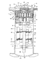
本発明に係るスクロール圧縮機100は、図2に示すように、縦型の密閉容器101内が低圧となるように、スクロール圧縮要素102から密閉容器101内上側に限られた空間として形成された吐出圧力空間111(マフラー室)に高圧冷媒ガスが吐出される内部低圧型のスクロール圧縮機である。
As shown in FIG. 2, the
密閉容器101は鋼板製であり、上下方向に沿って延びる縦長円筒状の容器本体101Aと、この容器本体101Aの上下両端にそれぞれ溶接固定された椀状のエンドキャップ101B及びボトムキャップ101Cとから構成されている。この密閉容器101内には、下側に駆動手段としての電動要素103が収納され、上側に電動要素103の回転軸105によって駆動されるスクロール圧縮要素102がそれぞれ収納されている。密閉容器101内のスクロール圧縮要素102と電動要素103の間には、上部支持フレーム104(メインフレームという)が収納されており、この上部支持フレーム104には中央に軸受部106とボス収容部122とが形成されている。この軸受部106は回転軸105の先端(上端)側を回転可能に軸支するためのものであり、上部支持フレーム104の一方の面(下側の面)の中央から下方に突出して形成されている。また、ボス収容部122は後述する揺動スクロール115のボス124を収容するためのものであり、上部支持フレーム104の他方の面(上側の面)の中央を下方に凹陥することにより形成されている。
The sealed
電動要素103下部の密閉容器101内には、下部支持フレーム107(ベアリングプレートという)が収納されており、この下部支持フレーム107の中央には軸受け108が形成されている。この軸受け108は、回転軸105の末端(下端)側を軸支するためのものであり、下部支持フレーム107の一方の面(下側の面)の中央から下方に突出して形成されている。そして、下部支持フレーム107の下側の空間、即ち、密閉容器101内の底部は、スクロール圧縮要素102などを潤滑する潤滑油が貯留されるオイル溜め162とされている。
A lower support frame 107 (referred to as a bearing plate) is accommodated in the sealed
回転軸105の先端(上端)には、偏心軸123が形成されている。この偏心軸123は、中心が回転軸105の軸心と偏心して設けられると共に、図示しないスライドブッシュ及び旋回軸受けを介して揺動スクロール115のボス124に、揺動スクロール115を旋回駆動可能に挿入されている。
An
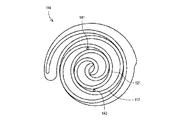
スクロール圧縮要素102は、固定スクロール114と揺動スクロール115とで構成されている。固定スクロール114は、円形状の鏡板116と、この鏡板116の一方の面(下側の表面)に立設されたインボリュート状、又は、これに近似した曲線からなる渦巻き状のラップ117と、このラップ117の周囲を取り囲むように立設された周壁118と、この周壁118の周囲(周壁118の他方の面側(上側))に突出して設けられ、外周縁が全周囲で密閉容器101の容器本体101Aの内面に焼き嵌めされたフランジ119とから一体に構成されている。そして、固定スクロール114は、フランジ119が全周囲で容器本体101Aの内面に焼き嵌め固定されると共に、鏡板116の中央部(固定スクロール114の中心)には、スクロール圧縮要素102にて圧縮された冷媒ガスを密閉容器101内上側に形成された吐出圧力空間111(マフラー室)に連通する吐出孔113が形成されている。係る固定スクロール114は、ラップ117の突出方向を下方としている。固定スクロール114のフランジ119が全周囲で容器本体101Aの内面に焼き嵌め固定されることにより、固定スクロール114によって密閉容器101内が、上部の吐出圧力空間111と下部の空間112に区分される。
The
電動要素103は、密閉容器101に固定された固定子150と、この固定子150の内側に配置され、固定子150内で回転する回転子152とから構成されており、この回転子152の中心に回転軸105が嵌合されている。固定子150は、複数枚の電磁鋼板を積層した積層体から成り、この積層体の歯部に巻装された固定子巻線151を有している。また、回転子152も固定子150と同様に電磁鋼板の積層体で形成されている。
The
また、回転軸105の内部には回転軸105の軸方向に沿って油路105Aが形成されており、この油路105Aは、回転軸105の下端に位置する吸込口161を備え、吸込口161がオイル溜め162に貯留された潤滑油に浸漬されて、潤滑油中に開口している。また、油路105Aには各軸受け106、108に対応する位置に潤滑を給油する給油口(図示せず)が形成されており、係る構成により、回転軸105が回転すると、オイル溜め162に貯留された潤滑油が回転軸105の吸込口161から油路105Aに入り、上方に汲み上げられる。そして、汲み上げられた潤滑油は各給油口等を介して各軸受け106、108やスクロール圧縮要素102の摺動部に供給されることとなる。
Further, an
密閉容器101には、密閉容器101内の下側の空間112内に冷媒を導入するための冷媒導入管145と、スクロール圧縮要素102にて圧縮され、前記吐出孔113から後述する吐出マフラー室128を介して密閉容器101内の上側の吐出圧力空間111に吐出された冷媒を外部に吐出するための冷媒吐出管146とが設けられている。尚、本実施例では、冷媒導入管145は密閉容器101の容器本体101Aの側面に溶接固定され、冷媒吐出管146はエンドキャップ101Bの側面に溶接固定されている。
The
上記のように、密閉容器101内の上側の吐出圧力空間111には、スクロール圧縮機100の外へ冷媒ガスを吐出する冷媒吐出管146が接続され、密閉容器101内の下側の空間112内には、冷媒を導入するための冷媒導入管145が接続されている。これによって、密閉容器101内の上部に高圧の吐出圧力空間111が形成されるが、スクロール圧縮要素102に吸い込まれる低圧冷媒ガスは、密閉容器101内の下側の空間112に流入した状態からスクロール圧縮要素102の吸入部へ吸い込まれる構成であるため、密閉容器101内の下側の空間112は低圧であり、これを以ってスクロール圧縮機100は、密閉容器101内が低圧となる内部低圧型のスクロール圧縮機を構成する。
As described above, the
一方、本実施例の構成では、固定スクロール114の鏡板116の上面130(ラップ117の反対側の面)が密閉容器101内の上側に形成された吐出圧力空間111に臨むように構成されている。固定スクロール114の鏡板116の上面130には、吐出孔113に連なる吐出弁と、この吐出弁に隣接して複数のリリース弁とが設けられている(吐出弁及びリリース弁は共に図示しない)。このリリース弁は、冷媒の過圧縮を防止するために設けられたものであり、図示しないリリースポートを介してスクロール圧縮要素102における圧縮過程の圧縮空間125に連通されている。
On the other hand, in the configuration of the present embodiment, the upper surface 130 (the surface opposite to the wrap 117) of the
密閉容器101内上側の吐出圧力空間111内には固定スクロール114にネジ止めされたカバー127が設けられている。このカバー127の下面中央には、固定スクロール114側から吐出圧力空間111方向に凹陥形成され、吐出圧力空間111と共にマフラー室を形成する吐出マフラー室128が形成されている。この吐出マフラー室128が吐出孔113に連通すると共に、図示しないがカバー127と固定スクロール114間に設けられた隙間を介して吐出マフラー室128と密閉容器101内上側の吐出圧力空間111内とが連通している。
A
具体的には、スクロール圧縮要素102における圧縮過程の冷媒圧力が吐出孔113に至る以前に吐出圧力に達すると、前記リリース弁が開放されて、圧縮空間125内の冷媒が前記リリースポートを介して外部に吐出されることとなる。
Specifically, when the refrigerant pressure in the compression process in the
揺動スクロール115は、上述した如き容器本体101Aの内面に焼き嵌め固定された固定スクロール114に対して旋回するスクロールであり、円板状の鏡板120と、この鏡板120の一方の面(上側の表面)に立設されたインボリュート状、又は、これに近似した曲線からなる渦巻き状のラップ121と、鏡板120の他方の面(下側の面)の中央に突出形成された前述したボス124とで構成されている。そして、揺動スクロール115はラップ121の突出方向を上方として、このラップ121が固定スクロール114のラップ117に180度回し、向かい合って噛み合うように配置され、内部のラップ117、121間に圧縮空間125が形成される。
The
即ち、揺動スクロール115のラップ121は、固定スクロール114のラップ117と対向し、両ラップ121、117の先端面が相手の底面(鏡板116面、及び、鏡板120面)に接するように噛み合い、且つ、揺動スクロール115は回転軸105の軸心から偏心して設けられた偏心軸123が回転可能に嵌合されている。このため、圧縮空間125は、2つの渦巻き状のラップ121、117が互いに偏心して、その偏心方向の線上で接して閉じこめられた複数の空間を作り、この空間の各々が圧縮室(低圧室や中間圧室、及び、高圧室などの複数の圧縮室)となる。
That is, the
固定スクロール114は、その周壁118の周囲に設けられたフランジ119が複数のボルト(図示せず)を介して上部支持フレーム104に固定されている。また、揺動スクロール115はオルダムリング148、及び、オルダムキーよりなるオルダム機構149によって上部支持フレーム104に支承されている。これにより、揺動スクロール115は、固定スクロール114に対して、自転せずに旋回運動を行うように構成されている。
In the fixed
この揺動スクロール115は、固定スクロール114に対して偏心して公転するため、2つの渦巻き状のラップ117、121の偏心方向と接触位置は回転しながら移動し、前記圧縮室は外側から内側の圧縮空間125に向かって移りながら次第に縮小していく。最初に外側の圧縮空間125から入り込んで低圧室に閉じこめられた低圧の冷媒ガスは、断熱圧縮されながら次第に内側に移動して中間圧(中間圧室)を経て、最後に中央部(高圧室)に到達するときには、高温高圧の冷媒ガスとなる。この冷媒ガスは、固定スクロール114の中心に形成された吐出孔113、及び、吐出マフラー室128を介して吐出圧力空間111に送り出される。
Since the
また、前記カバー127内(カバー127の板厚内部)には、後述のようにレシーバタンク(受液器)42内の液冷媒を、冷媒回路を構成する後述のリキッドインジェクション回路50Aを介してスクロール圧縮要素102の中間圧部に戻し、蒸発させることによって圧縮ガスの冷却を行うためのリキッドインジェクション通路144(後述のリキッドインジェクション回路50Aの一部)が形成されている(図2に図示)。このリキッドインジェクション通路144は、カバー127内で分岐して後述するインジェクション孔141、142に接続される。また、リキッドインジェクション通路144には、内部が中空のチューブにて構成された配管140が接続されており、この配管140の一端はカバー127のリキッドインジェクション通路144内に圧入され、他端はスリーブ139を介してエンドキャップ101Bに溶接固定されている。
In the cover 127 (inside the thickness of the cover 127), the liquid refrigerant in the receiver tank (liquid receiver) 42 is scrolled through a
また、固定スクロール114の鏡板116には、リキッドインジェクション通路144に連通するインジェクション孔141、142が上下方向に貫通形成されている。両インジェクション孔141、142の下側(揺動スクロール115側)は、ラップ117、121側に開口すると共に、スクロール圧縮要素102の中間圧部分(固定スクロール114の中心に形成された吐出孔113と同一の圧縮室になる直前、若しくは、その近傍の中間圧の位置)に連通している。係る、エンドキャップ101Bとカバー127間に渡って配管140が取り付けられると共に、配管140に接続された接続管147に、後述のように、レシーバタンク(受液器)42からのリキッドインジェクション回路50Aを構成する配管が接続されて、リキッドインジェクション通路144が形成されている。
In addition, the
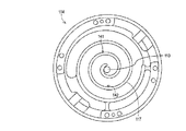
一方のインジェクション孔141は、図3に示すように固定スクロール114の中心を基準にして、他方のインジェクション孔142と180度ずれた位置に形成されている。そして、一方のインジェクション孔141は、固定スクロール114に立設されたラップ117の外側(揺動スクロール115のラップ121の内側に形成される高圧縮室側)に形成され、他方のインジェクション孔142は、固定スクロール114に立設されたラップ117の内側(揺動スクロール115のラップ121の外側に形成される高圧縮室側)に形成されている。
One
両インジェクション孔141、142は、後述のリキッドインジェクション回路50Aを介してスクロール圧縮要素102の中間圧部に連通するように形成される。図4に示すように、吐出孔113から高圧ガスの吐出が開始される以前に揺動スクロール115に立設されたラップ121にて閉塞される位置(中間圧縮室の高圧縮室近傍(圧縮室))に形成されており、スクロール圧縮要素102が冷媒を圧縮する工程において、後述のリキッドインジェクション回路50Aに連通した両インジェクション孔141、142が中間圧縮室に連通する。
Both injection holes 141 and 142 are formed so as to communicate with the intermediate pressure portion of the
なお、リキッドインジェクション回路50Aを介してスクロール圧縮要素102の圧縮空間125の低圧室へ液冷媒を供給するように、両インジェクション孔141、142をスクロール圧縮要素102の圧縮空間125の低圧室に連通するように形成することもできるが、以下の説明では、両インジェクション孔141、142をスクロール圧縮要素102の圧縮空間125の中間圧部である中間圧縮室に連通するように形成した構成において説明する。
Both injection holes 141 and 142 are communicated with the low pressure chamber of the
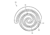
次に、図4〜図6を参照して、圧縮ガスの冷却説明を行う。この冷却は、後述のように、レシーバタンク42内の液冷媒の一部、またはレシーバタンク42を出て後述の膨張弁43に入るまでの液冷媒の一部が、後述のリキッドインジェクション回路50Aを介してスクロール圧縮要素102の中間圧部に戻り蒸発して圧縮ガスの冷却が行われ、揺動スクロール115は最終圧縮行程近傍に位置しているものとする。
Next, cooling of the compressed gas will be described with reference to FIGS. As will be described later, a part of the liquid refrigerant in the
図4に示す状態から揺動スクロール115が公転していくにしたがって、図5に示すように揺動スクロール115のラップ121にて閉塞されていた両インジェクション孔141、142は、中間圧縮部(圧縮空間125)へ開口する直前に位置する。このときは、高圧室(圧縮空間125)から吐出孔113への高温高圧の冷媒ガスの吐出が終了、若しくは、終了直前状態である。
As the
更に揺動スクロール115が公転していくと、図6に示すように、両インジェクション孔141、142から揺動スクロール115のラップ121が離間し、両インジェクション孔141、142は、中間圧室(圧縮空間125)に開口する。このときは、後述のレシーバタンク42内の液冷媒が後述のリキッドインジェクション回路50Aを介してスクロール圧縮要素102の中間圧部に戻り蒸発して圧縮ガスの冷却が行われる状態である。そして、更に揺動スクロール115が公転していくと、上記同様の動作を繰り返す。これによって、スクロール圧縮機100の圧縮ガスの冷却が行われる。
When the
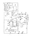
本発明に係る超低温冷凍回路1を示す冷媒配管図の一つの実施例を図1に示している。スクロール圧縮機100の高温高圧の吐出冷媒ガスの温度を検出する温度検知部60は、吐出孔113から凝縮器41へ導入されるまでの冷媒ガス温度を検知すればよく、その間のいずれかの箇所での冷媒の温度を検知する取り付けであればよい。このため、図1には、温度検知部60は、スクロール圧縮機100の出口である冷媒吐出管146から凝縮器41の入り口までのホットガス冷媒路71のホットガス冷媒の温度を検知する取り付けた構成を示し、また、図2には、温度検知部60は、密閉容器101及びカバー127の上壁を貫通するパイプ136の先端部(下端部)に収容されており、吐出孔113から上方へ吐出される冷媒ガスの温度を検知する構成を示している。
One embodiment of a refrigerant piping diagram showing an ultra-low
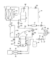
図1において、スクロール圧縮機100にて圧縮され、それぞれの吐出孔113から吐出マフラー室128及び吐出圧力空間111を経て冷媒吐出管146から吐出された高温高圧の冷媒ガス中にはオイルが混合されている。図1に示すように、スクロール圧縮機100にて圧縮された高温高圧の冷媒ガスは、オイルセパレータ40へ流入する。オイルセパレータ40では流入した冷媒ガス中のオイルが分離され、オイルが分離された冷媒ガスは、オイルセパレータ40の上部から凝縮器41へ流入して放熱され凝縮される。この放熱によって温度低下(例えば略50℃に低下)した液冷媒(一部にガス冷媒が混入している場合も含む)は、レシーバタンク42へその上部から入り、レシーバタンク42の底部に溜まった液冷媒がレシーバタンク42の底部から出て過冷却器411にて過冷却されて温度が低下し(例えば、略4〜5℃に低下)、その過冷却された液冷媒は、膨張弁43に流入して減圧膨張された後、蒸発器44へ流入して蒸発することにより、スーパーショーケースや冷凍庫等の所定の超低温冷凍領域を−40℃以下の所定の超低温に冷却する。そして、蒸発器44を出た冷媒は、アキュムレータ45を経由して再び冷媒導入管145よりスクロール圧縮要素102の吸込部へ吸い込まれて圧縮され、再び冷媒吐出管146ら吐出されて上記循環を繰り返すように動作する。
In FIG. 1, oil is mixed in the high-temperature and high-pressure refrigerant gas compressed by the
過冷却器411は、凝縮器41に併設されており、凝縮用電動ファン41Aにて放熱される構成である。このため、レシーバタンク42を出た液冷媒は、過冷却器411にて過冷却されることにより、冷凍能力の増加、及びスクロール圧縮機100の運転による消費電力の低減を図ることができるものとなる。アキュムレータ45は、後述の冷媒吸い込み路70の吸い込み冷媒に含まれる液冷媒を溜めて、スクロール圧縮機100へはガス冷媒が帰還するが液冷媒が帰還しないように気液分離するものである。
The
アキュムレータ45は、スクロール圧縮機100へ吸い込まれる冷媒中に液冷媒が含まれれば、その液冷媒を溜めて液冷媒が帰還しないようにして、スクロール圧縮機100へはガス冷媒が帰還するように気液分離するものである。蒸発器44は一つで示しているが、スーパーショーケースや冷凍庫等の所定の超低温冷凍領域が複数の場合は、それに応じて蒸発器44が複数並列接続され、蒸発器44ごとに 膨張弁43が接続される構成となる。凝縮器41及び過冷却器411は、空冷式または水冷式があり、空冷式の場合は凝縮用電動ファン41Aによって放熱される。また蒸発器44で冷却された空気は、冷却用電動ファン44Aによってスーパーショーケースや冷凍庫等の所定の超低温冷凍領域を超低温に冷却する空気循環が行われる。なお、47は循環する冷媒中のごみを取り除くフィルタと水分を吸着する乾燥剤を含むフィルタドライヤ、48はストレーナ、49は冷媒の流れを外部から目視するためのサイトグラスである。
If the refrigerant sucked into the
図1において、本発明に係る超低温冷凍装置では、フロン404Aの冷媒を使用して超低温を得ている。本発明の実施例では、スクロール圧縮機100に対して、スクロール圧縮要素2の温度上昇を抑制するために、レシーバタンク42の底部に溜まった液冷媒の一部が、リキッドインジェクション通路144からインジェクション孔141、142を通って、スクロール圧縮要素2の低圧部(低圧室)または中間圧部(中間圧室)へ導入するリキッドインジェクション回路50Aを備える。また、スクロール圧縮機100の出口である冷媒吐出管146から凝縮器41の入り口までのホットガス冷媒路71のホットガス冷媒の一部を、蒸発器44の出口からスクロール圧縮機100のスクロール圧縮要素2の吸込口までの冷媒吸い込み路70の吸い込み冷媒に合流させる冷媒供給路68を設けている。
In FIG. 1, the ultra-low temperature refrigeration apparatus according to the present invention uses the refrigerant of Freon 404A to obtain ultra-low temperature. In the embodiment of the present invention, in order to suppress the temperature rise of the scroll compression element 2 with respect to the
更に本発明に係る超低温冷凍装置は、図1に示すように、スクロール圧縮機100に対して、オイルセパレータ40の底部に溜まったオイルをスクロール圧縮機100の底部のオイル溜め162へ戻すためのオイルリターン回路52Aを備えている。
Further, as shown in FIG. 1, the ultra-low temperature refrigeration apparatus according to the present invention is an oil for returning the oil accumulated at the bottom of the
リキッドインジェクション回路50Aは、そこを流れる液冷媒の流量を所定値に調整する流量調整弁54Aと、スクロール圧縮機100の吐出冷媒ガス(即ち、ホットガス冷媒)の温度を検出するようにホットガス冷媒路71に取り付けた温度検知部60の検知に基づきリキッドインジェクション回路50Aを開く冷媒用電磁弁55Aが直列接続されている。図示の流量調整弁54Aは、ホットガス冷媒路71に取り付けた温度検知部60Aの温度検知に応じてキャピラリチューブ54A1内のガスの体積膨張・収縮によって流量を調整する弁機構であるガス封入式流量調整弁であるが、これに替わって、温度検知部60の温度検知に基づき後述の制御部62の動作によって流量を調整する弁機構である電動式流量調整弁であってもよい。流量調整弁54Aに並列にキャピラリチューブ58Pが接続されており、リキッドインジェクション回路50Aを流れる液冷媒が流量調整弁54Aとキャピラリチューブ58Pの両方を流れることにより、流量調整弁54Aの流量制御範囲を変更することができるものである。
The
リキッドインジェクション回路50Aによる圧縮要素102の低圧部(低圧室)または中間圧部(中間圧室)への液冷媒の供給は、スクロール圧縮要素102の低圧部(低圧室)または中間圧部(中間圧室)よりもレシーバタンク42内の圧力が高圧であることによる圧力差によって行なわれる。これによって、スクロール圧縮要素102の温度上昇が抑制される。なお、59Cはストレーナを示す。また、SV2は、修理・点検・メンテナンス等のときに手動でリキッドインジェクション回路50Aを閉じることができるサービス用バルブであり、通常はリキッドインジェクション回路50Aを開いている。
The liquid refrigerant is supplied to the low pressure portion (low pressure chamber) or the intermediate pressure portion (intermediate pressure chamber) of the
冷媒供給路68は、ホットガス冷媒路71のホットガス冷媒の一部を、キャピラリチューブ68P及び電磁弁構成のホットガス用開閉弁68Aの直列回路を介して冷媒吸い込み路70の吸い込み冷媒に合流させている。図1に示す実施例では、実線のように、冷媒供給路68の入り口は、ホットガス冷媒路71のうち、スクロール圧縮機100の出口である冷媒吐出管146からオイルセパレータ40の入り口までのホットガス冷媒路に接続され、冷媒供給路68の出口は、冷媒吸い込み路70のうちの蒸発器44の出口からアキュムレータ45の入り口までの冷媒吸い込み路70にGP部で接続されている。
The
なお、図1に点線68Yで示すように、冷媒供給路68の入り口は、ホットガス冷媒路71のうちオイルセパレータ40の出口から凝縮器41の入り口までのホットガス冷媒路に接続してもよく、またはオイルセパレータ40内の上部のホットガス領域に接続してもよい。また、冷媒供給路68の出口は、冷媒吸い込み路70のうちのアキュムレータ45の出口からスクロール圧縮機100の冷媒導入管145までの冷媒吸い込み路70の吸い込み冷媒に合流させるように接続してもよく、またはアキュムレータ45内の上部のガス冷媒領域に接続してもよい。
1, the inlet of the
オイルリターン回路52Aは、スクロール圧縮機100の底部のオイル溜め162のオイルレベルを検知するオイルレベル検知部61Aの検知に基づき、オイルリターン回路52Aを開閉するオイル用電磁弁57Aを備える。オイルリターン回路52Aには、流れるオイルの流量を所定値に調整する流路抵抗を有するキャピラリチューブ58Aをオイル用電磁弁57Aの下流に設けることができる。
The
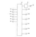
図7には、本発明に係る超低温冷凍装置の制御装置を示している。マイクロコンピュータ方式の制御部62を備え、制御部62の入力信号源として、温度検知部60、オイルレベル検知部61A、スーパーショーケースや冷凍庫等の所定の超低温冷凍領域の温度を検出する温度センサ63が接続され、更に、超低温冷凍装置の高圧部の圧力を検知するために、スクロール圧縮機100の高圧部の圧力を検出するように吐出孔113、マフラー室128または吐出圧力空間111の吐出冷媒ガスの圧力を検知するように設けた高圧センサ64、超低温冷凍装置の低圧部の圧力を検知するようにスクロール圧縮機100の低圧部である低圧空間112の冷媒ガスの圧力を検知する低圧センサ65、及び蒸発器44の出口からスクロール圧縮機100のスクロール圧縮要素2の吸込口までの冷媒吸い込み路70の温度を検知する温度検知部66等が接続されている。
FIG. 7 shows a control device for the cryogenic refrigeration apparatus according to the present invention. A microcomputer-
高圧センサ64は、スクロール圧縮機100の吐出圧力が異常高圧になったとき、スクロール圧縮機100の運転を停止するためのものであり、スクロール圧縮機100の吐出圧力の所定の高圧を検知したとき制御部62の動作によって、スクロール圧縮機100の運転を停止する。このため、高圧センサ64は、スクロール圧縮機100から吐出され凝縮器41へ導入されるまでの冷媒路の冷媒ガス圧力を検知するように、この冷媒路の配管のいずれか箇所の圧力を検知する取り付けであってもよい。また、低圧センサ65は、スクロール圧縮機100の吸入圧力(蒸発圧力)制御用センサであり、蒸発器44の出口からスクロール圧縮機100のスクロール圧縮要素2の吸入部までの冷媒吸い込み路70のいずれかの箇所の圧力を検知する取り付けであればよい。
The
また、制御部62の出力側には、温度センサ63等の検出に基づきスクロール圧縮機100の回転数制御を行うインバータ回路67、流量調整弁54A、冷媒用電磁弁55A、オイル用電磁弁57A、膨張弁43、凝縮用電動ファン41A、冷却用電動ファン44A、ホットガス用開閉弁68A等が接続されている。
Further, on the output side of the
上記の構成において、スクロール圧縮機100が運転されることによって、冷媒吐出管146から高温高圧の冷媒ガスが吐出され、オイルセパレータ40へ導入される。オイルの質量は冷媒ガスよりも大なるため、オイルセパレータ40に導入された冷媒ガスとそれに含まれるオイルが分離され、オイルはオイルセパレータ40の底部に溜まり、冷媒ガスはオイルセパレータ40の上部から凝縮器41へ流入して放熱され凝縮される。この放熱によって温度低下した(例えば略50℃に低下)液冷媒(一部にガス冷媒が混入している場合も含む)は、レシーバタンク42へその上部から入り、レシーバタンク42の底部に溜まった液冷媒がレシーバタンク42の底部から出て過冷却器411にて過冷却されて温度が低下し(例えば、略4〜5℃に低下)、その過冷却された液冷媒は、膨張弁43に流入して減圧膨張された後、蒸発器44へ流入して蒸発することにより、スーパーショーケースや冷凍庫等の所定の超低温冷凍領域を−40℃以下の超低温に冷却する。そして、蒸発器44を出た冷媒は、冷媒吸い込み路70に設けたアキュムレータ45を経由して再び冷媒導入管145よりスクロール圧縮要素2の吸込部へ吸い込まれて圧縮され、再び冷媒吐出管146から吐出されて上記循環を繰り返すように動作する。
In the above configuration, when the
本発明に係る超低温冷凍装置は、−40℃以下の超低温、例えば−50℃や−60℃等に設定した設定温度で運転されるものであり、スクロール圧縮機100の運転に基づく冷媒循環によって蒸発器44の蒸発温度は低下し、冷却用電動ファン44Aの運転によって冷気循環が行なわれて、スーパーショーケースや冷凍庫等の食品貯蔵領域である所定の超低温冷凍領域の温度が低下し、−40℃以下の設定した所定の超低温に冷却される。この冷却によって超低温冷凍領域の温度が設定した所定の下限温度に低下すると、この温度を温度センサ63が検出することによって、制御部62の動作に基づき一定速度回転のスクロール圧縮機100の場合は、その運転を停止し、且つ凝縮用電動ファン41A及び冷却用電動ファン44Aの運転を停止する。また、スクロール圧縮機100がインバータ制御方式の場合は、超低温冷凍領域の温度が低下する従ってスクロール圧縮機100の回転数が低下し、所定の下限温度に低下した状態で、この温度を維持するようにスクロール圧縮機100は低速回転数で運転される。この動作と共に、膨張弁43の開度も制御部62によって制御されると共に、凝縮用電動ファン41A及び冷却用電動ファン44Aの運転が制御される。
The ultra-low temperature refrigeration apparatus according to the present invention is operated at an ultra-low temperature of −40 ° C. or lower, for example, a set temperature set to −50 ° C., −60 ° C. or the like, and is evaporated by refrigerant circulation based on the operation of the
本発明に係る超低温冷凍装置は、上記のようにリキッドインジェクション回路50Aを備えている。これによって、スクロール圧縮機100においては、温度検知部60が所定の高温度を検知することにより、制御部62の動作に基づいて冷媒用電磁弁55Aが開き、レシーバタンク42の底部の液冷媒の一部がリキッドインジェクション回路50Aによって、インジェクション孔141、142からスクロール圧縮要素102の低圧部または中間圧部分へ供給され、スクロール圧縮要素102の温度上昇を抑制する。この場合、温度検知部60の検知温度に応じた制御部62の動作に基づいて、設定温度を超える温度差が大きい場合は液冷媒の流量が多く、設定温度を超える温度差が小さい場合は液冷媒の流量が少なくなるように、電動式流量調整弁54Aによる液冷媒の流量が所定値に調整される。このようなスクロール圧縮要素102の低圧部または中間圧部分への液冷媒の供給は、スクロール圧縮要素102の低圧部または中間圧部分よりもレシーバタンク42内の圧力が高圧であることによる圧力差によって行なわれる。これによって、スクロール圧縮要素102の温度上昇が抑制される。
The ultra-low temperature refrigeration apparatus according to the present invention includes the
また、本発明に係る超低温冷凍装置は、上記のように、オイルリターン回路52Aを備えている。これによって、スクロール圧縮機100の底部のオイル溜め162のオイルレベルを検知するオイルレベル検知部61Aが下限レベルを検知したことにより、制御部62の動作に基づいてオイル用電磁弁57Aが開き、オイルセパレータ40の底部に溜まったオイルが、キャピラリチューブ58Aにより所定流量に制限された状態で、オイルリターン回路52Aから密閉容器1内底部のオイル溜め162に供給され、オイル溜め162のオイル不足を解消する。このようなオイル溜め162へのオイルの供給は、密閉容器1内底部のオイル溜め162の圧力よりもオイルセパレータ40内の圧力が高圧であることによる圧力差によって行なわれる。
The ultra-low temperature refrigeration apparatus according to the present invention includes the
また、本発明に係る超低温冷凍装置は、−40℃以下の超低温、例えば−45℃〜−60℃のうちの設定温度で運転されるものであるが、蒸発器44における過熱度が大きくなった場合や、膨張弁43の動作不良により正常な絞り効果が得られない場合等では、蒸発器44から冷媒吸い込み路70を通ってスクロール圧縮機100へ帰還する冷媒温度が規定値の範囲よりも大きく低下して、−50℃以下になることがある。このような超低温冷媒が冷媒吸い込み路70からスクロール圧縮機100に帰還すれば、この冷媒吸い込み路70に設けたアキュムレータ45等の吸い込み側部品やスクロール圧縮機100に使用されている材料がこの超低温に耐えられるような特殊な材料で構成されていない場合は、経時変化によってスクロール圧縮機100が動作不良などの事態を招くようになる。
Further, the ultra-low temperature refrigeration apparatus according to the present invention is operated at an ultra-low temperature of −40 ° C. or lower, for example, a set temperature of −45 ° C. to −60 ° C., but the degree of superheat in the
本発明はこのようなことを防止するために、上記のように冷媒供給路68を設けている。これによって、蒸発器44を出た冷媒温度が規定値(上記のように法規制された値、現時点では−50℃)以下の低温度の冷媒がスクロール圧縮機100へ継続して吸い込まれることを防止するために、蒸発器44を出た冷媒温度が所定の冷凍温度に低下した状態で、スクロール圧縮機100へ帰還する冷媒が、規定値(−50℃)以下の温度状態で継続して吸い込まれることがないように昇温する。
In the present invention, in order to prevent this, the
このための一つの実施例として、スクロール圧縮機100の運転によって、冷媒吸い込み路70の冷媒温度が、規定値(本発明の実施例では−50℃としている)に低下する前の所定温度(実施例では−49℃)に低下したことを温度検知部66が検出することにより、制御部62の動作により、それまで閉じていた電磁弁68Aを開き、ホットガス冷媒路71のホットガス冷媒の一部を、キャピラリチューブ68P及びホットガス用開閉弁68Aの直列回路を有する冷媒供給路68を通して、冷媒吸い込み路70の吸い込み冷媒に合流させ、冷媒吸い込み路70の冷媒温度を上昇させる。このようにホットガス冷媒が、冷媒供給路68を通して冷媒吸い込み路70の吸い込み冷媒に合流されるのは、冷媒供給路68の入り口側と出口側の圧力差によって行なわれる。
As one embodiment for this purpose, a predetermined temperature (implementation) before the refrigerant temperature in the
このホットガス冷媒の混合によって上昇した温度は、温度検知部66が検出するため、例えば、温度検知部66が−45℃に上昇したことを検出することにより、制御部62の動作により、電磁弁68Aを閉じて冷媒供給路68から冷媒吸い込み路70へのホットガス供給を停止する。この停止の後に、再度冷媒吸い込み路70の冷媒温度が規定値(−50℃)未満の所定の冷凍温度(実施例では−49℃)に低下したことを温度検知部66が検出した場合は、上記同様にして冷媒供給路68を通してホットガス冷媒の供給によって、スクロール圧縮機100に対する安全な温度まで、冷媒吸い込み路70の吸い込み冷媒の温度を上昇させることができるものとなる。
Since the
図1に示すように、温度検知部66は、冷媒供給路68の出口が冷媒吸い込み路70に接続されるGP部よりも下流側、即ち、スクロール圧縮機100の冷媒導入管145寄りの部分において、冷媒吸い込み路70の吸い込み冷媒の温度を検知するように取り付けられている。これによって、冷媒吸い込み路70の吸い込み冷媒の温度状態の検知が的確となり、冷媒吸い込み路70の吸い込み冷媒の温度が所定の低温になった状態で電磁弁68Aを開く制御と、冷媒供給路68からのホットガス冷媒によって冷媒吸い込み路70の吸い込み冷媒の温度が所定の温度に上昇した状態で、電磁弁68Aを閉じる制御が的確に行なえるものとなる。
As shown in FIG. 1, the
上記において、ホットガス用開閉弁68Aが開く温度を、規定値(−50℃)に近いが−50℃未満の温度とし、例えば、−45℃〜−49℃の範囲の所定の温度を温度検知部66が検知することにより、蒸発器44を出た冷媒に冷凍装置のホットガス冷媒を混合させて、冷媒吸い込み路70の吸い込み冷媒の温度を−50℃よりも十分高い温度の冷媒とすることができる。これによって、冷媒吸い込み路70に設けたアキュムレータ45等の吸い込み側部品やスクロール圧縮機100に使用されている材料が、規定値(−50℃)以下の超低温に耐えられるような特殊な材料で構成されていない場合の保護ができるものとなる。なお、ホットガス用開閉弁68Aが開く温度を、規定値(−50℃)からあまり離れすぎた温度とすると、無闇にホットガス冷媒による混合が行なわれることとなり、好ましくない。
In the above, the temperature at which the hot gas on-off
図8には、本発明に係る超低温冷凍装置の第2実施例の冷媒配管図である。実施例1はホットガス冷媒の供給によって、冷媒吸い込み路70の吸い込み冷媒の温度を安全な温度まで上昇させるものであるが、ホットガスのように温度の高い冷媒を利用しなくても吸い込み冷媒の温度を安全な温度まで上昇させ得る場合は、レシーバタンク42のウォームガス冷媒を利用して、冷媒吸い込み路70の吸い込み冷媒の温度を所定の温度に上昇させることができる。この方式が実施例2であり、以下にそれについて記載する。
FIG. 8 is a refrigerant piping diagram of the second embodiment of the cryogenic refrigeration apparatus according to the present invention. In the first embodiment, the supply of hot gas refrigerant raises the temperature of the refrigerant sucked in the
上記実施例1と同様部分には同一符号付しており、その構成及び作用は実施例1と同様である。この図8の構成が図1の構成と異なるところは、冷媒供給路68が、実施例1のホットガス冷媒供給に替わって、レシーバタンク42内の上部に溜まったウォームガス冷媒の一部が、キャピラリチューブ68P及びホットガス用開閉弁68Aの直列回路を有する冷媒供給路68を通して、冷媒吸い込み路70の吸い込み冷媒にGPで合流させ、冷媒吸い込み路70の冷媒温度を上昇させる配管構成である。
The same parts as those in the first embodiment are denoted by the same reference numerals, and the configuration and operation thereof are the same as those in the first embodiment. The configuration of FIG. 8 differs from the configuration of FIG. 1 in that the
このため、図8に示す実施例では、冷媒供給路68の入り口は、レシーバタンク42内の上部のウォームガス冷媒を導入する位置に接続され、冷媒供給路68の出口は、冷媒吸い込み路70のうちの蒸発器44の出口からアキュムレータ45の入り口までの冷媒吸い込み路にGP部で接続されている。
For this reason, in the embodiment shown in FIG. 8, the inlet of the
このため、実施例1と同様に、冷媒吸い込み路70の冷媒温度が規定値(−50℃)未満の所定の冷凍温度(例えば−49℃)に低下したことを温度検知部66が検出することにより、制御部62の動作によりそれまで閉じていた電磁弁68Aを開き、レシーバタンク42内のウォームガス冷媒の一部をキャピラリチューブ68P及びホットガス用開閉弁68Aの直列回路を有する冷媒供給路68を通して、冷媒吸い込み路70の吸い込み冷媒に合流させ、冷媒吸い込み路70の冷媒温度を上昇させる。このようにウォームガス冷媒が、冷媒供給路68を通して冷媒吸い込み路70の吸い込み冷媒に合流されるのは、冷媒供給路68の入り口側と出口側の圧力差によって行なわれる。
For this reason, the
このウォームガス冷媒の混合によって上昇した温度は温度検知部66が検出するため、例えば温度検知部66が−45℃に上昇したことを検出することにより、制御部62の動作により、電磁弁68Aを閉じて冷媒供給路68から冷媒吸い込み路70へのウォームガス冷媒の供給を停止する。この停止の後に、再度冷媒吸い込み路70の冷媒温度が規定値(−50℃)未満の所定の冷凍温度、例えば−49℃に低下したことを温度検知部66が検出した場合は、上記同様にして冷媒供給路68を通してウォームガス冷媒の供給によって、スクロール圧縮機100等に対する安全な温度まで、冷媒吸い込み路70の吸い込み冷媒の温度を上昇させることができる。
Since the
この実施例2においても、レシーバタンク42を出た液冷媒は、過冷却器411にて過冷却されることにより、冷凍能力の増加、及びスクロール圧縮機100の運転による消費電力の低減を図ることができるものとなる。
Also in the second embodiment, the liquid refrigerant that has exited the
本発明に係るスクロール圧縮機は、上記実施例に示した構成に限定されず、内部高圧タイプの種々の形態のものにも適用できるものであり、本発明の技術範囲において種々の形態を包含するものである。 The scroll compressor according to the present invention is not limited to the configuration shown in the above embodiment, and can be applied to various types of internal high-pressure types, and includes various forms within the technical scope of the present invention. Is.
40・・・・オイルセパレータ
41・・・・凝縮器
411・・・過冷却器
41A・・・凝縮用電動ファン
42・・・・レシーバタンク
43・・・・膨張弁
44・・・・蒸発器
44A・・・冷却用電動ファン
50A・・・リキッドインジェクション回路
52A・・・オイルリターン回路
54A・・・流量調整弁
55A・・・冷媒用電磁弁
57A・・・オイル用電磁弁
58A・・・キャピラリチューブ
60・・・・温度検知部
61A・・・オイルレベル検知部
62・・・・制御部
63・・・・超低温冷凍領域の温度を検出する温度センサ
64・・・・高圧センサ
65・・・・低圧センサ
66・・・・温度検知部
67・・・・インバータ回路
68・・・・冷媒供給路
68A・・・ホットガス用開閉弁
68P・・・キャピラリチューブ
70・・・・冷媒吸い込み路
71・・・・ホットガス冷媒路
100・・・スクロール圧縮機
101・・・密閉容器
102・・・スクロール圧縮要素
103・・・電動要素
105・・・回転軸
104・・・上支持フレーム(メインフレーム)
111・・・吐出圧力空間
113・・・吐出孔
114・・・固定スクロール
116・・・固定スクロールの鏡板
117・・・固定スクロールのラップ
115・・・揺動スクロール
120・・・揺動スクロールの鏡板
121・・・揺動スクロールのラップ
125・・・圧縮空間
127・・・カバー
128・・・吐出マフラー室
141・・・インジェクション孔
142・・・インジェクション孔
144・・・リキッドインジェクション通路
162・・・オイル溜め
40 ...
DESCRIPTION OF
Claims (2)
Priority Applications (1)
| Application Number | Priority Date | Filing Date | Title |
|---|---|---|---|
| JP2011118046A JP5877331B2 (en) | 2011-05-26 | 2011-05-26 | Refrigeration system with scroll compressor |
Applications Claiming Priority (1)
| Application Number | Priority Date | Filing Date | Title |
|---|---|---|---|
| JP2011118046A JP5877331B2 (en) | 2011-05-26 | 2011-05-26 | Refrigeration system with scroll compressor |
Publications (2)
| Publication Number | Publication Date |
|---|---|
| JP2012247104A JP2012247104A (en) | 2012-12-13 |
| JP5877331B2 true JP5877331B2 (en) | 2016-03-08 |
Family
ID=47467711
Family Applications (1)
| Application Number | Title | Priority Date | Filing Date |
|---|---|---|---|
| JP2011118046A Expired - Fee Related JP5877331B2 (en) | 2011-05-26 | 2011-05-26 | Refrigeration system with scroll compressor |
Country Status (1)
| Country | Link |
|---|---|
| JP (1) | JP5877331B2 (en) |
Families Citing this family (2)
| Publication number | Priority date | Publication date | Assignee | Title |
|---|---|---|---|---|
| ES2939683T3 (en) | 2016-11-01 | 2023-04-26 | Weiss Technik Gmbh | test chamber |
| WO2019171600A1 (en) | 2018-03-09 | 2019-09-12 | 日立ジョンソンコントロールズ空調株式会社 | Refrigeration cycle device |
Family Cites Families (9)
| Publication number | Priority date | Publication date | Assignee | Title |
|---|---|---|---|---|
| JPH05340616A (en) * | 1992-06-12 | 1993-12-21 | Daikin Ind Ltd | Freezer device |
| JPH0719610A (en) * | 1993-07-05 | 1995-01-20 | Mitsubishi Electric Corp | Refrigerating plant |
| JP2000179952A (en) * | 1998-12-09 | 2000-06-30 | Nishiyodo Kuchoki Kk | Refrigeration cycle controller |
| US6637222B2 (en) * | 2000-06-07 | 2003-10-28 | Samsung Electronics Co., Ltd. | System for controlling starting of air conditioner and control method thereof |
| US6374621B1 (en) * | 2000-08-24 | 2002-04-23 | Cincinnati Sub-Zero Products, Inc. | Refrigeration system with a scroll compressor |
| JP3433197B2 (en) * | 2002-07-10 | 2003-08-04 | 三洋電機株式会社 | Refrigerant circuit |
| JP3835478B1 (en) * | 2005-04-18 | 2006-10-18 | ダイキン工業株式会社 | Air conditioner |
| JP5506219B2 (en) * | 2009-03-25 | 2014-05-28 | 三菱電機株式会社 | Refrigerant compressor and fluid compressor |
| JP5436982B2 (en) * | 2009-08-28 | 2014-03-05 | 三洋電機株式会社 | Scroll compressor |
-
2011
- 2011-05-26 JP JP2011118046A patent/JP5877331B2/en not_active Expired - Fee Related
Also Published As
| Publication number | Publication date |
|---|---|
| JP2012247104A (en) | 2012-12-13 |
Similar Documents
| Publication | Publication Date | Title |
|---|---|---|
| US7914267B2 (en) | Multistage compressor for a CO2 cycle that includes a rotary compressing mechanism and a scroll compressing mechanism | |
| JP5695187B2 (en) | Refrigerant compressor and refrigeration cycle apparatus using the same | |
| JP4807071B2 (en) | Refrigeration equipment | |
| JP5017037B2 (en) | Refrigeration cycle equipment | |
| JP6253278B2 (en) | Refrigeration cycle | |
| JP5510393B2 (en) | Multistage compression refrigeration cycle equipment | |
| WO2017061167A1 (en) | Multi-stage compressor and refrigeration system equipped with same | |
| JP5903595B2 (en) | Ultra-low temperature refrigeration equipment | |
| JP2008144643A (en) | Multiple stage compressor and refrigeration cycle using the same | |
| JP4591350B2 (en) | Refrigeration equipment | |
| JP6783579B2 (en) | Scroll compressor | |
| JP5877331B2 (en) | Refrigeration system with scroll compressor | |
| JP2012247105A (en) | Cryogenic refrigerator with scroll compressor | |
| JP2017194064A (en) | Refrigeration cycle | |
| KR20190090701A (en) | Refrigeration apparatus | |
| WO2012101864A1 (en) | Oil separator, and compressor and refrigeration cycle equipped with same | |
| JP7047416B2 (en) | Air conditioner | |
| JP5934931B2 (en) | Tank for refrigeration cycle apparatus and refrigeration cycle apparatus including the same | |
| JP5877361B2 (en) | Ultra-low temperature refrigeration system with scroll compressor | |
| WO2010122812A1 (en) | Refrigeration cycle device | |
| JP4241127B2 (en) | Transcritical refrigerant cycle equipment | |
| JP2004271127A (en) | Freezing device | |
| KR100711637B1 (en) | Compressor | |
| JP5950807B2 (en) | Compressor | |
| KR200351087Y1 (en) | Compressor |
Legal Events
| Date | Code | Title | Description |
|---|---|---|---|
| A621 | Written request for application examination |
Free format text: JAPANESE INTERMEDIATE CODE: A621 Effective date: 20140521 |
|
| A711 | Notification of change in applicant |
Free format text: JAPANESE INTERMEDIATE CODE: A711 Effective date: 20141107 |
|
| RD02 | Notification of acceptance of power of attorney |
Free format text: JAPANESE INTERMEDIATE CODE: A7422 Effective date: 20141114 |
|
| A521 | Written amendment |
Free format text: JAPANESE INTERMEDIATE CODE: A523 Effective date: 20150122 |
|
| A977 | Report on retrieval |
Free format text: JAPANESE INTERMEDIATE CODE: A971007 Effective date: 20150122 |
|
| A131 | Notification of reasons for refusal |
Free format text: JAPANESE INTERMEDIATE CODE: A131 Effective date: 20150210 |
|
| A521 | Written amendment |
Free format text: JAPANESE INTERMEDIATE CODE: A523 Effective date: 20150409 |
|
| TRDD | Decision of grant or rejection written | ||
| A01 | Written decision to grant a patent or to grant a registration (utility model) |
Free format text: JAPANESE INTERMEDIATE CODE: A01 Effective date: 20150811 |
|
| A61 | First payment of annual fees (during grant procedure) |
Free format text: JAPANESE INTERMEDIATE CODE: A61 Effective date: 20150909 |
|
| R151 | Written notification of patent or utility model registration |
Ref document number: 5877331 Country of ref document: JP Free format text: JAPANESE INTERMEDIATE CODE: R151 |
|
| LAPS | Cancellation because of no payment of annual fees |