以下、本発明に係るシートベルト用リトラクタについて具体化した一実施形態に基づき図面を参照しつつ詳細に説明する。
DETAILED DESCRIPTION Hereinafter, a seat belt retractor according to an embodiment of the present invention will be described in detail with reference to the drawings based on an embodiment.
[概略構成]
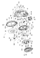
先ず、本実施形態に係るシートベルト用リトラクタ1の概略構成について図1乃至図3に基づき説明する。図1は本実施形態に係るシートベルト用リトラクタ1の外観斜視図である。図2及び図3はシートベルト用リトラクタ1をユニット別に分解した斜視図である。
図1乃至図3に示すように、シートベルト用リトラクタ1は、車両のウエビング3を巻き取るための装置であって、ハウジングユニット5と、巻取ドラムユニット6と、プリテンショナユニット7と、巻取バネユニット8と、ロックユニット9とから構成されている。
[Schematic configuration]
First, a schematic configuration of the seatbelt retractor 1 according to the present embodiment will be described with reference to FIGS. 1 to 3. FIG. 1 is an external perspective view of a seatbelt retractor 1 according to this embodiment. 2 and 3 are exploded perspective views of the seat belt retractor 1 for each unit.
As shown in FIGS. 1 to 3, the seat belt retractor 1 is a device for winding a webbing 3 of a vehicle, and includes a housing unit 5, a winding drum unit 6, a pretensioner unit 7, and a winding unit. A spring unit 8 and a lock unit 9 are included.
また、ロックユニット9は、メカニズムカバー71(図5参照)に一体に形成された各ナイラッチ9A及び各係止フック9Bによって、ハウジングユニット5を構成するハウジング11の一方の側壁部12に固設されている。そして、ロックユニット9は、後述のようにウエビング3の急激な引き出しや車両の急激な加速度の変化に反応してウエビング3の引き出しを停止するロック機構10を構成する(図10参照)。また、巻取バネユニット8は、バネケース67(図5参照)の外周部から突出した3個の板状の係止片8A(図6参照)を介して、後述のようにロックユニット9の巻取ドラムユニット6の回転軸方向外側に固設されている(図8参照)。
Further, the lock unit 9 is fixed to one side wall portion 12 of the housing 11 constituting the housing unit 5 by means of each ny latch 9A and each locking hook 9B formed integrally with the mechanism cover 71 (see FIG. 5). ing. The lock unit 9 constitutes a lock mechanism 10 that stops the pull-out of the webbing 3 in response to a sudden pull-out of the webbing 3 or a rapid acceleration change of the vehicle, as will be described later (see FIG. 10). The take-up spring unit 8 winds the lock unit 9 as described later via three plate-like locking pieces 8A (see FIG. 6) protruding from the outer periphery of the spring case 67 (see FIG. 5). The drum unit 6 is fixed to the outer side in the rotation axis direction (see FIG. 8).
また、プリテンショナユニット7は、平面視略コの字状に形成されたハウジング11の側壁部12に相対向する他方の側壁部13に、プリテンショナユニット7の巻取ドラムユニット6の回転軸方向外側から挿通される各ネジ15によってネジ止めされる。また、プリテンショナユニット7は、プリテンショナユニット7の巻取ドラムユニット6の回転軸方向外側から側壁部13に挿通されるストッパーピン16と、該ストッパーピン16に側壁部13の巻取ドラムユニット6の回転軸方向内側から挿入されるプッシュナット18によって固定される。
Further, the pretensioner unit 7 is arranged on the other side wall portion 13 opposite to the side wall portion 12 of the housing 11 formed in a substantially U shape in plan view, and on the outer side in the rotation axis direction of the winding drum unit 6 of the pretensioner unit 7. Are screwed by the respective screws 15 inserted therethrough. The pretensioner unit 7 includes a stopper pin 16 inserted into the side wall portion 13 from the outer side in the rotation axis direction of the winding drum unit 6 of the pretensioner unit 7, and the rotation of the winding drum unit 6 of the side wall portion 13 through the stopper pin 16. It is fixed by a push nut 18 inserted from the inside in the axial direction.
そして、ウエビング3が巻装される巻取ドラムユニット6は、ハウジングユニット5の側壁部12に固設されたロックユニット9と、側壁部13に固定されたプリテンショナユニット7との間に回転自在に支持される。また、巻取ドラムユニット6は、ロックユニット9の外側に固設された巻取バネユニット8によって、ウエビング3の巻取方向に常時付勢されている。
The winding drum unit 6 around which the webbing 3 is wound is rotatable between a lock unit 9 fixed to the side wall 12 of the housing unit 5 and a pretensioner unit 7 fixed to the side wall 13. Supported. The winding drum unit 6 is always urged in the winding direction of the webbing 3 by a winding spring unit 8 fixed outside the lock unit 9.
[ハウジングユニットの概略構成]
次に、ハウジングユニット5の概略構成について図2乃至図4に基づいて説明する。
図4はハウジングユニット5の分解斜視図である。
図2乃至図4に示すように、ハウジングユニット5は、ハウジング11と、ブラケット21と、プロテクタ22と、パウル23と、パウルリベット25と、捩りコイルバネ26と、センサカバー27と、車両加速度センサ28と、連結部材32、33と、リベット61とから構成されている。
[Schematic configuration of housing unit]
Next, a schematic configuration of the housing unit 5 will be described with reference to FIGS.
FIG. 4 is an exploded perspective view of the housing unit 5.
As shown in FIGS. 2 to 4, the housing unit 5 includes a housing 11, a bracket 21, a protector 22, a pawl 23, a pawl rivet 25, a torsion coil spring 26, a sensor cover 27, and a vehicle acceleration sensor 28. And connecting members 32 and 33 and a rivet 61.
また、ハウジング11は、車体に固定される背板部31と、その背板部31の両側縁部から相対向する各側壁部12、13が延出されて、平面視略コの字状にスチール材等で形成されている。また、各側壁部12、13は、巻取ドラムユニット6の回転軸方向に長い横長細板状の各連結部材32、33によって互いに連結されている。また、背板部31の中央部には、開口部が形成され、軽量化及びウエビング3の収容量の規制等が図られている。
Further, the housing 11 is formed in a substantially U shape in plan view by extending a back plate portion 31 fixed to the vehicle body and side wall portions 12 and 13 facing each other from both side edge portions of the back plate portion 31. It is made of steel. Further, the side wall portions 12 and 13 are connected to each other by connecting members 32 and 33 each having a horizontally long thin plate shape that is long in the direction of the rotation axis of the winding drum unit 6. In addition, an opening is formed in the central portion of the back plate portion 31 so as to reduce the weight and limit the amount of webbing 3 accommodated.
また、側壁部12には巻取ドラムユニット6のラチェットギヤ35が、所定隙間(例えば、約0.5mmの隙間である。)を形成しつつ挿入される貫通孔36が形成されている。この貫通孔36の内側周縁部は、巻取ドラムユニット6側へ中心軸方向内側に所定深さ窪んで、巻取ドラムユニット6のラチェットギヤ35に対向するように構成されている。
Further, the side wall portion 12 is formed with a through hole 36 into which the ratchet gear 35 of the winding drum unit 6 is inserted while forming a predetermined gap (for example, a gap of about 0.5 mm). The inner peripheral edge of the through hole 36 is configured to be recessed to the winding drum unit 6 side by a predetermined depth inward in the central axis direction, and to be opposed to the ratchet gear 35 of the winding drum unit 6.
また、この貫通孔36の斜め下側(図4中、斜め左下側である。)のパウル23の各係合歯23A、23Bを含む先端(他方の端部)側の部分37に対向する周縁部から、該パウル23の回動方向外側へ(パウル23のラチェットギヤ35から離反する回動方向である。)、この先端側の部分37が収容される深さに切り欠かれた切欠部38が形成されている。この切欠部38の背板部31側の横側には、パウル23を回転可能に取り付けるための貫通孔41が形成されている。また、切欠部38の貫通孔41側のパウル23が当接する部分には、該貫通孔41と同軸に円弧状の案内部38Aが形成されている。
Further, a peripheral edge facing the tip 37 (the other end) side portion 37 including the engaging teeth 23A and 23B of the pawl 23 obliquely below (through the diagonally lower left in FIG. 4) of the through hole 36. The notch portion 38 is cut out to a depth in which the distal end portion 37 is accommodated from the portion to the outside in the turning direction of the pawl 23 (the turning direction is away from the ratchet gear 35 of the pawl 23). Is formed. A through hole 41 for rotatably mounting the pawl 23 is formed on the side of the notch 38 on the back plate 31 side. In addition, an arcuate guide portion 38 </ b> A is formed coaxially with the through hole 41 at a portion where the pawl 23 on the through hole 41 side of the cutout portion 38 abuts.
一方、スチール材等で形成されたパウル23の案内部38Aに当接して摺動する部分には、側壁部12の厚さ寸法にほぼ等しい高さで、この案内部38Aと同じ曲率半径の円弧状に窪んだ段差部37Aが形成されている。また、パウル23の回動軸方向外側(図4中、手前側である。)の側面の先端部には、ロックユニット9を構成するクラッチ85のガイド孔116(図5、図10参照)に挿入される案内ピン42が立設されている。
On the other hand, a portion of the pawl 23 made of steel or the like that slides in contact with the guide portion 38A has a height substantially equal to the thickness of the side wall portion 12 and has the same radius of curvature as the guide portion 38A. A stepped portion 37A that is recessed in an arc is formed. Further, a guide hole 116 (see FIGS. 5 and 10) of the clutch 85 constituting the lock unit 9 is provided at the tip of the side surface of the pawl 23 on the outer side in the rotational axis direction (the front side in FIG. 4). A guide pin 42 to be inserted is erected.
また、パウル23の基端部(一方の端部)にはパウルリベット25が挿通される貫通孔43が形成されると共に、この貫通孔43の周縁部から側壁部12の貫通孔41に回動可能に挿通される円筒状のボス部45が、側壁部12の厚さ寸法にほぼ等しい高さで立設されている。そして、パウル23は、ボス部45が側壁部12の貫通孔41にハウジング11の内側から挿通された状態で、側壁部12の外側から貫通孔43に嵌入されたパウルリベット25によって、回動可能に固定される。これにより、パウル23の各係合歯23A、23Bとラチェットギヤ35の外周面に形成されたラチェットギヤ部35Aとが、側壁部12の外側面とほぼ同一面になるように配置される。
A through hole 43 through which the pawl rivet 25 is inserted is formed at the base end portion (one end portion) of the pawl 23 and is rotated from the peripheral portion of the through hole 43 to the through hole 41 of the side wall portion 12. A cylindrical boss portion 45 that can be inserted is erected at a height substantially equal to the thickness dimension of the side wall portion 12. The pawl 23 can be rotated by a pawl rivet 25 fitted into the through hole 43 from the outside of the side wall portion 12 in a state where the boss portion 45 is inserted into the through hole 41 of the side wall portion 12 from the inside of the housing 11. Fixed to. Accordingly, the engaging teeth 23A and 23B of the pawl 23 and the ratchet gear portion 35A formed on the outer peripheral surface of the ratchet gear 35 are arranged so as to be substantially flush with the outer surface of the side wall portion 12.
また、パウルリベット25の頭部は、貫通孔41よりも大きい外径で所定厚さ(例えば、厚さ約1.5mmである。)の円板状に形成されている。そして、リターンスプリングの一例として機能する捩りコイルバネ26は、巻き数が1巻きでパウルリベット25の頭部の周囲を囲むように配置され、一端側26Aがパウル23の案内ピン42に取り付けられている。また、捩りコイルバネ26の線径は、パウルリベット25の頭部の高さのほぼ半分の寸法である(例えば、線径約0.6mmである。)。従って、捩りコイルバネ26の1巻き分のバネ高さは、パウルリベット25の頭部の高さとほぼ同じ高さに設定されている。
The head of the pawl rivet 25 is formed in a disk shape having a larger outer diameter than the through hole 41 and a predetermined thickness (for example, a thickness of about 1.5 mm). The torsion coil spring 26, which functions as an example of a return spring, is disposed so as to surround the head of the pawl rivet 25 with one winding, and one end side 26 </ b> A is attached to the guide pin 42 of the pawl 23. . The wire diameter of the torsion coil spring 26 is approximately half the height of the head of the pawl rivet 25 (for example, the wire diameter is about 0.6 mm). Accordingly, the height of one turn of the torsion coil spring 26 is set to be substantially the same as the height of the head of the pawl rivet 25.
また、捩りコイルバネ26の他端側26Bは、側壁部12上を摺接可能に一端側26Aの側壁部12側を通った後、側壁部12の内側方向(図4中、側壁部12の裏側方向である。)へ略直角に折り曲げられて、側壁部12に形成された取付孔46に挿通されている。また、この他端側26Bの端部は、略U字形に折り曲げられて側壁部12の内側面に当接され、抜け止め部を構成している。これにより、パウル23は、捩りコイルバネ26によって切欠部38の奥側方向へ(図3中、反時計方向である。)回動するように付勢され、各係合歯23A、23Bを含む先端側の部分37が切欠部38の奥側に当接される。従って、パウル23は、捩りコイルバネ26によってラチェットギヤ35から離反する方向へ回動付勢されている。
Further, the other end side 26B of the torsion coil spring 26 passes through the side wall portion 12 side of the one end side 26A so as to be slidable on the side wall portion 12, and then the inner side direction of the side wall portion 12 (in FIG. 4, the back side of the side wall portion 12). Direction), and is inserted through a mounting hole 46 formed in the side wall portion 12. Further, the end portion of the other end side 26B is bent into a substantially U shape and is brought into contact with the inner surface of the side wall portion 12 to constitute a retaining portion. As a result, the pawl 23 is biased by the torsion coil spring 26 so as to rotate toward the back side of the notch 38 (in the counterclockwise direction in FIG. 3), and the distal end including the engaging teeth 23A and 23B. The side portion 37 is in contact with the back side of the notch 38. Accordingly, the pawl 23 is urged to rotate in a direction away from the ratchet gear 35 by the torsion coil spring 26.
また、図2乃至図4に示すように、側壁部12の貫通孔36の下方(図4中、下方向である。)には、貫通孔36の中心軸の下方(図4中、下方向である。)から背板部31側の部分に、略四角形の開口部47が形成されている。また、この開口部47には、開口部47とほぼ同じ断面略四角形の浅い略箱体状のセンサカバー27が外側(図4中、手前側である。)から嵌入される。そして、樹脂製のセンサカバー27は、開口側周縁部に形成された鍔部が開口部47の外側周縁部(図4中、手前側周縁部である。)に当接されると共に、センサカバー27の図4中、上下方向両端面に突設された一対の係止爪27A(図4中、上側端面の係止爪27Aを図示している。)が開口部47の図4中、上下方向両端部の奥側に嵌入されて弾性的に係止される。
Further, as shown in FIGS. 2 to 4, below the through hole 36 of the side wall portion 12 (downward in FIG. 4), below the central axis of the through hole 36 (downward in FIG. 4). To the back plate portion 31 side, a substantially rectangular opening 47 is formed. In addition, a shallow substantially box-shaped sensor cover 27 having a substantially square cross section substantially the same as the opening 47 is fitted into the opening 47 from the outside (the front side in FIG. 4). The resin-made sensor cover 27 has a flange formed on the opening-side peripheral edge abutting on the outer peripheral edge of the opening 47 (the front-side peripheral edge in FIG. 4), and the sensor cover. 27, a pair of locking claws 27A (in FIG. 4, the locking claw 27A on the upper end surface is shown) projecting from both ends in the up-down direction are shown in FIG. It is inserted in the back side of the direction both ends and is elastically locked.
また、車両加速度センサ28は、鉛直方向上側(図4中、上側である。)に開放される略箱形で底面部にすり鉢状の載置部が形成された樹脂製のセンサーホルダ51と、スチール等の金属で球状体に形成されて載置部上に移動可能に載置された慣性質量体52と、慣性質量体52の鉛直方向上側に載置されてパウル23に対して反対側の端縁部(図4中、右端縁部である。)をセンサーホルダ51によって鉛直方向上下(図4中、上下方向である。)に揺動可能に支持される樹脂製のセンサレバー53とから構成されている。
Further, the vehicle acceleration sensor 28 includes a resin-made sensor holder 51 having a substantially box shape opened to the upper side in the vertical direction (upper side in FIG. 4) and having a mortar-shaped mounting portion formed on the bottom surface portion, Inertial mass 52 formed in a spherical body of metal such as steel and movably mounted on the mounting portion, and placed on the upper side in the vertical direction of inertial mass 52 and opposite to pawl 23 From the sensor lever 53 made of resin, the end edge portion (the right end edge portion in FIG. 4) is supported by the sensor holder 51 so as to be swingable vertically (in the vertical direction in FIG. 4). It is configured.
そして、車両加速度センサ28をセンサカバー27へ嵌入して、センサーホルダ51のセンサカバー27内の両側壁部に対向する両側面部に設けられた一対の係止爪51A(図4中、一方の係止爪51Aを図示している。)をセンサカバー27の各係止孔27Bに嵌入して係止することによって、車両加速度センサ28がセンサカバー27を介してハウジング11に取り付けられる。
Then, the vehicle acceleration sensor 28 is fitted into the sensor cover 27, and a pair of locking claws 51 </ b> A (one engagement in FIG. 4) provided on both side surfaces facing both side walls in the sensor cover 27 of the sensor holder 51. The vehicle acceleration sensor 28 is attached to the housing 11 via the sensor cover 27 by inserting and locking the pawl 51A into each locking hole 27B of the sensor cover 27.
また、側壁部12には、上端縁部(図4中、上側端縁部である。)の両隅と、貫通孔36の下方(図4中、下方向である。)との3箇所に、ロックユニット9の各ナイラッチ9Aが嵌入されて取り付けられる各取付孔55が形成されている。また、側壁部12の左右側縁部の中央部(図4中、上下方向中央部である。)には、ロックユニット9の各係止フック9Bが弾性的に係止される各係止片56が、巻取ドラムユニット6の回転軸に対して直交するように張り出して形成されている。
Further, the side wall portion 12 has three corners, that is, both corners of an upper edge portion (upper edge portion in FIG. 4) and a lower portion of the through hole 36 (downward direction in FIG. 4). Each mounting hole 55 into which each ny latch 9A of the lock unit 9 is fitted and attached is formed. In addition, each locking piece to which each locking hook 9 </ b> B of the lock unit 9 is elastically locked is located at the center of the left and right side edges of the side wall 12 (the vertical center in FIG. 4). 56 is formed so as to protrude perpendicularly to the rotation axis of the winding drum unit 6.
また、側壁部13には、巻取ドラムユニット6が挿通される貫通孔57が中央部に形成されている。また、側壁部13には、下端縁部(図2中、下側端縁部である。)の略中央及び連結部材33側の角部と、上端縁部(図2中、上側端縁部である。)の背板部31側の角部に、各ネジ15がネジ止めされる各ネジ孔58がプリテンショナユニット7側方向へのバーリングによって形成されている。また、側壁部13には、上端縁部(図2中、上側端縁部である。)の連結部材32側の角部にストッパーピン16が挿通される貫通孔59が形成されている。
Further, a through hole 57 through which the winding drum unit 6 is inserted is formed in the side wall portion 13 at the center portion. Further, the side wall portion 13 includes a substantially lower end edge portion (lower end edge portion in FIG. 2), a corner portion on the connecting member 33 side, and an upper end edge portion (upper end edge portion in FIG. 2). The screw holes 58 into which the screws 15 are screwed are formed by burring in the direction of the pretensioner unit 7 at the corners on the back plate portion 31 side. Further, a through hole 59 through which the stopper pin 16 is inserted is formed in the side wall portion 13 at a corner portion on the connecting member 32 side of the upper end edge portion (the upper end edge portion in FIG. 2).
また、背板部31の上端縁部(図2中、上側端縁部である。)に各リベット61によって取り付けられるブラケット21は、スチール材等で形成されて、背板部31の上端縁部から略直角に連結部材32側方向に延出された延出部に、ウエビング3が引き出される背板部31の幅方向に長い横長の貫通孔62が形成され、ナイロン等の合成樹脂で形成された横長枠状のプロテクタ22が嵌め込まれている。また、背板部31の下端部(図2中、下端部である。)には、車両の締結片(不図示)に取り付ける際に、ボルトが挿通されるボルト挿通孔63が形成されている。
Moreover, the bracket 21 attached to each upper end edge (the upper end edge in FIG. 2) of the back plate 31 by each rivet 61 is formed of a steel material or the like, and the upper end edge of the back plate 31 A laterally long through hole 62 extending in the width direction of the back plate portion 31 from which the webbing 3 is pulled out is formed in an extending portion extending in the direction of the connecting member 32 at a substantially right angle from the side, and is formed of a synthetic resin such as nylon. A horizontally long frame-shaped protector 22 is fitted. Further, a bolt insertion hole 63 through which a bolt is inserted when being attached to a fastening piece (not shown) of the vehicle is formed in the lower end portion (the lower end portion in FIG. 2) of the back plate portion 31. .
[巻取バネユニットの概略構成]
次に、巻取バネユニット8の概略構成について図2、図3、図5乃至図8、図11に基づいて説明する。
図5及び図6は、ラチェットギヤを含む巻取バネユニット8及びロックユニット9の分解斜視図である。図7及び図8は、バネケース67の取り付けを説明する断面図である。図11はシートベルト用リトラクタ1の巻取バネユニット8及びロックユニット9を含む要部拡大断面図である。
[Schematic configuration of winding spring unit]
Next, a schematic configuration of the winding spring unit 8 will be described with reference to FIGS. 2, 3, 5 to 8, and 11.
5 and 6 are exploded perspective views of the winding spring unit 8 and the lock unit 9 including the ratchet gear. 7 and 8 are cross-sectional views for explaining the attachment of the spring case 67. FIG. FIG. 11 is an enlarged cross-sectional view of a main part including the winding spring unit 8 and the lock unit 9 of the seat belt retractor 1.
図2、図3、図5、図6及び図11に示すように、巻取バネユニット8は、渦巻バネ65と、この渦巻バネ65の外側端65Aが内側周縁部の底面から立設されたリブ66に固定されると共に、この渦巻バネ65を収容するバネケース67と、渦巻バネ65の内側端65Bが連結されてバネ力が付勢されるバネシャフト68とから構成されている。また、バネケース67は、ロックユニット9を構成するメカニズムカバー71側の端縁部に、ほぼ全周に渡って所定深さ(例えば、深さ約2.5mmである。)の溝部67Aが形成されている。
2, 3, 5, 6, and 11, the winding spring unit 8 includes a spiral spring 65 and an outer end 65 </ b> A of the spiral spring 65 erected from the bottom surface of the inner peripheral edge. A spring case 67 that is fixed to the rib 66 and accommodates the spiral spring 65, and a spring shaft 68 to which the inner end 65B of the spiral spring 65 is connected and the spring force is urged are configured. Further, the spring case 67 is formed with a groove portion 67A having a predetermined depth (for example, a depth of about 2.5 mm) over the entire circumference at the edge portion on the mechanism cover 71 side constituting the lock unit 9. ing.
また、バネケース67のメカニズムカバー71側の端縁部には、外周部の3箇所から正面視略長方形の板状の各係止片8Aが、メカニズムカバー71の略中央部に形成された貫通孔73の中心軸73Aに対して同心状に突設されている。また、各係止片8Aの貫通孔73の中心軸73Aに対して半径方向外側の外周面は、同心円上に位置するように形成されている。
Further, at the edge of the spring case 67 on the mechanism cover 71 side, plate-shaped locking pieces 8A having a substantially rectangular shape in front view from three locations on the outer peripheral portion are formed in through holes formed in a substantially central portion of the mechanism cover 71. The projection 73 is concentrically provided with respect to the central shaft 73 </ b> A. In addition, the outer peripheral surface on the outer side in the radial direction with respect to the central axis 73A of the through hole 73 of each locking piece 8A is formed so as to be located concentrically.
また、図6及び図7に示すように、バネケース67の下端縁部に位置する係止片8Aには、貫通孔73の中心軸73Aに対して反時計方向側の端縁部に連続して断面四角形の固定部8Bが連設されている。また、固定部8Bの略中央部には、貫通孔73の中心軸73Aに平行な貫通孔8Cが形成されると共に、この貫通孔8Cの該中心軸73A方向外側の端部を塞ぐように固定ピン8Dが一体的に形成されている。
Further, as shown in FIGS. 6 and 7, the locking piece 8 </ b> A located at the lower end edge of the spring case 67 is continuous with the end edge on the counterclockwise direction side with respect to the central axis 73 </ b> A of the through hole 73. A fixed portion 8B having a square cross section is provided continuously. In addition, a through hole 8C parallel to the central axis 73A of the through hole 73 is formed at a substantially central portion of the fixed part 8B, and fixed so as to close an end of the through hole 8C on the outer side in the central axis 73A direction. The pin 8D is integrally formed.
また、固定ピン8Dの軸径は、貫通孔8Cの内径とほぼ同じ径に形成され、固定ピン8Dを所定荷重以上でメカニズムカバー71側へ押すことによって、貫通孔8C内に押し込むことができる。また、固定ピン8Dの長さは、固定部8Bの厚さよりも長くなるように形成されている。
Further, the shaft diameter of the fixing pin 8D is formed to be substantially the same as the inner diameter of the through hole 8C, and the fixing pin 8D can be pushed into the through hole 8C by pushing the fixing pin 8D toward the mechanism cover 71 with a predetermined load or more. Further, the length of the fixing pin 8D is formed so as to be longer than the thickness of the fixing portion 8B.
一方、メカニズムカバー71は、外周部の各係止片8Aに対向する3箇所から、断面略矩形の厚板状の保持部72が、巻取バネユニット8側に突設されている。また、図5及び図7に示すように、各保持部72の基端部には、貫通孔73の中心軸73Aに対して反時計回り方向に切り欠かれて、奥側端部が閉塞された断面略長方形の嵌合溝部72Aが形成されている。
On the other hand, the mechanism cover 71 has thick plate-like holding portions 72 having a substantially rectangular cross section protruding from the three locations facing the respective locking pieces 8A on the outer peripheral portion on the winding spring unit 8 side. As shown in FIGS. 5 and 7, the base end portion of each holding portion 72 is notched in the counterclockwise direction with respect to the central axis 73 </ b> A of the through hole 73, and the back end portion is closed. A fitting groove 72A having a substantially rectangular cross section is formed.
また、各嵌合溝部72Aの貫通孔73の中心軸73Aに対して半径方向外側の底面部は、バネケース67の各係止片8Aの半径方向外側端縁部よりも少し大きい半径(例えば、約0.2mm〜0.5mm大きい半径である。)の同心円上に位置するように形成されている。また、各嵌合溝部72Aの中心軸73A方向の幅寸法は、各係止片8Aの厚さ寸法とほぼ同じ寸法に形成され、後述のように、各係止片8Aは各嵌合溝部72A内に嵌入されるように構成されている(図8参照)。
In addition, the bottom surface portion on the radially outer side with respect to the central axis 73A of the through hole 73 of each fitting groove portion 72A has a slightly larger radius (for example, approximately about the outer edge in the radial direction of each locking piece 8A of the spring case 67). The radius is larger by 0.2 mm to 0.5 mm.). Further, the width dimension of each fitting groove 72A in the direction of the central axis 73A is formed to be approximately the same as the thickness dimension of each locking piece 8A. As will be described later, each locking piece 8A has each fitting groove 72A. It is comprised so that it may insert in (refer FIG. 8).
また、メカニズムカバー71は、巻取ドラムユニット6の回転軸方向外側の周縁部に沿って所定高さ(例えば、高さ約2mmである。)で立設された略リング状のリブ部71Aが設けられている。リブ部71Aは、溝部67Aに対応した位置に設けられており、リブ部71Aの内径及び外径は、溝部67Aの内径及び外径に対して、溝部64Aにリブ部71Aが嵌入された状態でそれぞれ所定の隙間(例えば、隙間約0.1mm〜0.3mmである。)を形成するように設けられている。
The mechanism cover 71 is provided with a substantially ring-shaped rib portion 71A standing at a predetermined height (for example, a height of about 2 mm) along the outer peripheral edge of the winding drum unit 6 in the rotation axis direction. It has been. The rib portion 71A is provided at a position corresponding to the groove portion 67A, and the inner diameter and the outer diameter of the rib portion 71A are in a state in which the rib portion 71A is fitted in the groove portion 64A with respect to the inner diameter and the outer diameter of the groove portion 67A. Each is provided so as to form a predetermined gap (for example, a gap of about 0.1 mm to 0.3 mm).
また、図5乃至図7に示すように、リブ部71Aの下端縁部に対向する保持部72の中心軸73Aに対して時計方向側の近傍には、後述のように、バネケース67をメカニズムカバー71に取り付けた際に、固定ピン8Dに対向する位置に、断面円形の固定用孔74が形成されている。
Further, as shown in FIGS. 5 to 7, in the vicinity of the central axis 73A of the holding portion 72 facing the lower end edge of the rib portion 71A, the spring case 67 is provided in the mechanism cover as will be described later. When attached to 71, a fixing hole 74 having a circular cross section is formed at a position facing the fixing pin 8D.
この固定用孔74の内径は、バネケース67の固定ピン8Dの外径よりも所定寸法(例えば、約0.1mm〜0.3mmである。)だけ小さくなるように形成され、固定ピン8Dを圧入できるように設けられている。また、固定用孔74の奥側、つまり、ハウジング11の側壁部12側の周縁部には、奥側が閉塞された円筒状のボス75が立設されている。また、この円筒状のボス75の内径は、固定用孔74と同じ直径の断面円形に形成されると共に、固定用孔74に対して同軸に形成されている。
The inner diameter of the fixing hole 74 is formed to be smaller than the outer diameter of the fixing pin 8D of the spring case 67 by a predetermined dimension (for example, about 0.1 mm to 0.3 mm), and the fixing pin 8D is press-fitted. It is provided so that it can. In addition, a cylindrical boss 75 whose rear side is closed is erected on the rear side of the fixing hole 74, that is, on the peripheral edge portion on the side wall 12 side of the housing 11. Further, the inner diameter of the cylindrical boss 75 is formed in a circular cross section having the same diameter as that of the fixing hole 74 and is formed coaxially with the fixing hole 74.
ここで、巻取バネユニット8をメカニズムカバー71へ取り付ける取付方法について説明する。
図6に示すように、先ず、渦巻バネ65の外側端65Aをバネケース67の内側に立設されたリブ66に嵌入して、バネケース67内に収納して、渦巻バネ65の内側端65Bにバネシャフト68の取付溝68Cを嵌め込む。また、図5及び図6に示すように、バネシャフト68は、バネケース67の底面部の略中心位置に立設されたピン69が、底面部の貫通孔68Aに挿入されて、底面部側がピン69の周縁部に回転可能に当接される。
Here, an attachment method for attaching the take-up spring unit 8 to the mechanism cover 71 will be described.
As shown in FIG. 6, first, the outer end 65 </ b> A of the spiral spring 65 is fitted into a rib 66 erected on the inner side of the spring case 67 and housed in the spring case 67, and the spring is connected to the inner end 65 </ b> B of the spiral spring 65. The mounting groove 68C of the shaft 68 is fitted. As shown in FIGS. 5 and 6, the spring shaft 68 has a pin 69 erected at a substantially central position of the bottom surface portion of the spring case 67 and is inserted into the through hole 68A in the bottom surface portion, and the bottom surface portion side is pinned. 69 is rotatably abutted on the peripheral edge of 69.
そして、図7に示すように、バネケース67の外周部の3箇所から半径方向外側に突設された各係止片8Aを、メカニズムカバー71の保持部72の正面視時計方向側の端縁部に対向するように位置させる。また、図5及び図11に示すように、メカニズムカバー71の貫通孔73から突出するロッキングギヤ81の回転軸部93の先端部93Aは、断面矩形状に形成されると共に、中心軸に沿って、ピン69が挿入される軸孔93Bが形成されている。
Then, as shown in FIG. 7, each locking piece 8 </ b> A protruding radially outward from three locations on the outer peripheral portion of the spring case 67 is connected to the edge portion of the holding portion 72 of the mechanism cover 71 on the front view clockwise side. Position it so as to face. Further, as shown in FIGS. 5 and 11, the distal end portion 93 </ b> A of the rotating shaft portion 93 of the locking gear 81 protruding from the through hole 73 of the mechanism cover 71 is formed in a rectangular cross-section and along the central axis. A shaft hole 93B into which the pin 69 is inserted is formed.
続いて、図6及び図11に示すように、メカニズムカバー71の貫通孔73から突出するロッキングギヤ81の回転軸部93の先端部93Aを、バネシャフト68の断面矩形状に形成された筒孔68B内に嵌入して、ロッキングギヤ81の回転軸部93を当該バネシャフト68に対して相対回転不能に連結する。また同時に、図7に示すように、バネケース67の溝部67A内に、メカニズムカバー71の周縁部に立設されたリブ部71Aを嵌入する。
Subsequently, as shown in FIGS. 6 and 11, the distal end portion 93 </ b> A of the rotating shaft portion 93 of the locking gear 81 protruding from the through hole 73 of the mechanism cover 71 is formed in a cylindrical hole formed in a rectangular cross section of the spring shaft 68. The rotary shaft portion 93 of the locking gear 81 is connected to the spring shaft 68 so as not to be relatively rotatable. At the same time, as shown in FIG. 7, the rib portion 71 </ b> A standing on the peripheral edge portion of the mechanism cover 71 is inserted into the groove portion 67 </ b> A of the spring case 67.
そして、図7及び図8に示すように、バネケース67をウエビング引出方向、つまり、正面視反時計方向(図7中、矢印70方向である。)へ回転させて、バネケース67の各係止片8Aをメカニズムカバー71の各保持部72の嵌合溝部72A内に嵌入して、各嵌合溝部72Aの奥側に当接させる。これにより、バネケース67がメカニズムカバー71の貫通孔73の中心軸73Aに対して、半径方向及び軸方向に移動しないように位置決めされる。
Then, as shown in FIGS. 7 and 8, the spring case 67 is rotated in the webbing pull-out direction, that is, in the counterclockwise direction when viewed from the front (in the direction of arrow 70 in FIG. 7). 8A is inserted into the fitting groove portion 72A of each holding portion 72 of the mechanism cover 71 and is brought into contact with the back side of each fitting groove portion 72A. Accordingly, the spring case 67 is positioned so as not to move in the radial direction and the axial direction with respect to the central axis 73A of the through hole 73 of the mechanism cover 71.
その後、この状態で、バネケース67の固定ピン8Dを押圧して、固定部8Bの貫通孔8Cとメカニズムカバー71の固定用孔74とに圧入することによって、巻取バネユニット8がメカニズムカバー71に対して相対回転不能に固定され、巻取バネユニット8がメカニズムカバー71の巻取ドラムユニット6の回転軸方向外側に当接された状態で取り付けられる。
Thereafter, in this state, the fixing pin 8 </ b> D of the spring case 67 is pressed and press-fitted into the through hole 8 </ b> C of the fixing portion 8 </ b> B and the fixing hole 74 of the mechanism cover 71, whereby the winding spring unit 8 is inserted into the mechanism cover 71. On the other hand, the winding spring unit 8 is fixed in a relatively non-rotatable manner, and is attached in a state where the winding spring unit 8 is in contact with the outer side in the rotation axis direction of the winding drum unit 6 of the mechanism cover 71.
これにより、メカニズムカバー71の周縁部に立設されたリブ部71Aが、バネケース67の溝部67Aに嵌入されて、バネケース67内への粉塵や埃等の侵入が防止される。また、図11に示すように、バネシャフト68におけるメカニズムカバー71の底面部側が、ピン69の周縁部に回転可能に当接された状態で、バネシャフト68のロックユニット9側の端部と、メカニズムカバー71の略中央部に形成された貫通孔73の背面側周縁部との間に所定隙間(例えば、隙間約0.3mmである。)が形成されている。
As a result, the rib portion 71 </ b> A erected on the peripheral portion of the mechanism cover 71 is fitted into the groove portion 67 </ b> A of the spring case 67, and dust and dust are prevented from entering the spring case 67. Further, as shown in FIG. 11, the end of the spring shaft 68 on the lock unit 9 side with the bottom surface of the mechanism cover 71 in contact with the peripheral edge of the pin 69 so as to be rotatable, A predetermined gap (for example, a gap of about 0.3 mm) is formed between the peripheral edge portion of the through hole 73 formed in the substantially central portion of the mechanism cover 71.
また、同時に、バネシャフト68の筒孔68Bの底面と、ロッキングギヤ81の回転軸部93の先端部93Aとの間にも所定隙間(例えば、隙間約0.3mmである。)が形成されている。従って、バネシャフト68は、バネケース67とメカニズムカバー71との間において、所定隙間分だけ、中心軸73Aの軸方向に移動可能に設けられている。
At the same time, a predetermined gap (for example, a gap of about 0.3 mm) is also formed between the bottom surface of the cylindrical hole 68B of the spring shaft 68 and the distal end portion 93A of the rotating shaft portion 93 of the locking gear 81. Yes. Therefore, the spring shaft 68 is provided between the spring case 67 and the mechanism cover 71 so as to be movable in the axial direction of the central shaft 73A by a predetermined gap.
[ロック機構の概略構成]
次に、ウエビング3の急激な引き出しや車両の急激な加速度の変化に反応してウエビング3の引き出しを停止するロック機構10を構成するロックユニット9の概略構成について図5、図6、図9乃至図18に基づいて説明する。
[Schematic configuration of locking mechanism]
Next, FIG. 5, FIG. 6, FIG. 9 thru | or FIG. 9 about schematic structure of the lock unit 9 which comprises the lock mechanism 10 which stops the pull-out of the webbing 3 in response to the rapid change of the webbing 3 and the rapid acceleration of a vehicle. This will be described with reference to FIG.
図9はロックユニット9のロックアームを含む組立断面図である。図10はロックユニット9のメカニズムカバー71の底面部等の一部を切り欠いた一部切り欠き断面図である。図12はクラッチの外側斜視図である。図13はクラッチの内側斜視図である。図14はクラッチを斜め下から見た斜視図である。図15及び図16はパイロットレバーの斜視図である。図17はパイロットレバーの通常時の状態を示す要部拡大図である。図18はパイロットレバーがロッキングギヤに係合した状態を示す要部拡大図である。
FIG. 9 is an assembly sectional view including the lock arm of the lock unit 9. FIG. 10 is a partially cutaway cross-sectional view in which a part of the bottom surface of the mechanism cover 71 of the lock unit 9 is cut away. FIG. 12 is an outer perspective view of the clutch. FIG. 13 is an inside perspective view of the clutch. FIG. 14 is a perspective view of the clutch as viewed obliquely from below. 15 and 16 are perspective views of the pilot lever. FIG. 17 is an enlarged view of a main part showing a normal state of the pilot lever. FIG. 18 is an enlarged view of a main part showing a state where the pilot lever is engaged with the locking gear.
図5、図6、図9乃至図11に示すように、ロックユニット9は、メカニズムカバー71、ロッキングギヤ81、ロックアーム82、センサスプリング83、クラッチ85及びパイロットレバー86で構成されている。尚、本実施形態においては、ロックユニット9を構成する各部材のうち、センサスプリング83を除いた部材は、合成樹脂で成形されており、互いに接触した場合の部材間の摩擦係数は小さなものである。
As shown in FIGS. 5, 6, and 9 to 11, the lock unit 9 includes a mechanism cover 71, a locking gear 81, a lock arm 82, a sensor spring 83, a clutch 85, and a pilot lever 86. In the present embodiment, among the members constituting the lock unit 9, the members excluding the sensor spring 83 are formed of synthetic resin, and the friction coefficient between the members when they are in contact with each other is small. is there.
メカニズムカバー71は、ハウジング11の側壁部12側が開口された略円形の底面部を有する略箱体状のメカニズム収容部87が形成され、ロッキングギヤ81やクラッチ85等を収容するように構成されている。また、メカニズムカバー71は、ハウジング11にセンサカバー27を介して取り付けられた車両加速度センサ28に対向する角部(図6中、左下角部である。)に、断面略四角形の凹形状に形成されたセンサ収容部88が設けられている。
The mechanism cover 71 is formed with a substantially box-shaped mechanism housing portion 87 having a substantially circular bottom surface that is open on the side wall 12 side of the housing 11, and is configured to house the locking gear 81, the clutch 85, and the like. Yes. Further, the mechanism cover 71 is formed in a concave shape having a substantially square cross section at a corner portion (the lower left corner portion in FIG. 6) facing the vehicle acceleration sensor 28 attached to the housing 11 via the sensor cover 27. The sensor housing portion 88 is provided.
そして、メカニズムカバー71を各ナイラッチ9A及び各係止フック9Bによって側壁部12に取り付けた場合には、車両加速度センサ28のセンサーホルダ51がセンサ収容部88に嵌入されて、センサレバー53が鉛直方向上下(図6中、上下方向である。)に揺動可能に収納されるように構成されている。また、メカニズムカバー71のメカニズム収容部87の下端部略中央部(図6中、下端部略中央部である。)には、当該メカニズム収容部87とセンサ収容部88とが連通するように開設された開口部89が形成されている。
When the mechanism cover 71 is attached to the side wall portion 12 by the ny latches 9A and the locking hooks 9B, the sensor holder 51 of the vehicle acceleration sensor 28 is fitted into the sensor housing portion 88, and the sensor lever 53 is moved in the vertical direction. It is configured so as to be swingable vertically (in the vertical direction in FIG. 6). Further, the mechanism housing portion 87 and the sensor housing portion 88 are opened so as to communicate with the lower end portion substantially central portion (in FIG. 6, the lower end portion substantially central portion) of the mechanism cover portion 71 of the mechanism cover 71. An opening 89 is formed.
この開口部89は、車両加速度センサ28のセンサレバー53の先端縁部から上方向(図6中、上方向である。)に向けて突設されたロック爪53Aの先端部が鉛直方向上下(図6中、上下方向である。)に進退可能に形成され、通常時には、ロック爪53Aの先端部は、パイロットレバー86の受け板部122(図10参照)の近傍に位置している。そして、後述のように、所定値を超える加速度によって慣性質量体52が移動してセンサレバー53が鉛直方向上側へ回動された場合には、ロック爪53Aは開口部89を介してパイロットレバー86の受け板部122に当接して、パイロットレバー86を鉛直方向上側へ回動させるように構成されている(図27参照)。
The opening 89 has a vertically extending vertical end of the lock claw 53A that protrudes upward from the front edge of the sensor lever 53 of the vehicle acceleration sensor 28 (the upward direction in FIG. 6). In FIG. 6, the front end of the lock claw 53 </ b> A is positioned in the vicinity of the receiving plate portion 122 (see FIG. 10) of the pilot lever 86. As will be described later, when the inertial mass body 52 is moved by acceleration exceeding a predetermined value and the sensor lever 53 is rotated upward in the vertical direction, the lock claw 53A is connected to the pilot lever 86 via the opening 89. The pilot lever 86 is configured to rotate upward in the vertical direction by contacting the receiving plate portion 122 (see FIG. 27).
また、メカニズム収容部87の略円形の底面部には、中央部に形成された貫通孔73の周縁部から円筒状の支持ボス91が立設されている。この支持ボス91のロッキングギヤ81側の先端部の外周は、全周に渡って先端側へ所定角度(例えば、約30°の傾斜角である。)で傾斜した先細りの面取り部91Aが形成されている。また、この支持ボス91には、ロッキングギヤ81の円板状の底面部92の中央部に、メカニズムカバー71に対向する背面側から突出する円筒状の回転軸部93が嵌入され、摺動回転可能に支持される。
Further, a cylindrical support boss 91 is erected on the substantially circular bottom surface portion of the mechanism accommodating portion 87 from the peripheral edge portion of the through hole 73 formed in the central portion. The outer periphery of the tip end portion of the support boss 91 on the side of the locking gear 81 is formed with a tapered chamfered portion 91A inclined at a predetermined angle (for example, an inclination angle of about 30 °) toward the tip end over the entire circumference. ing. The support boss 91 is fitted with a cylindrical rotary shaft portion 93 protruding from the back side facing the mechanism cover 71 at the center portion of the disc-shaped bottom surface portion 92 of the locking gear 81 for sliding rotation. Supported as possible.
ロッキングギヤ81は、円板状の底面部92の全周からクラッチ85側へ円環状に立設されて、外周部にパイロットレバー86に係合するロッキングギヤ歯81Aが形成されている。このロッキングギヤ歯81Aは、ロッキングギヤ81がウエビング引出方向へ回転した時のみ、パイロットレバー86の係合爪部86Aと係合するように形成されている(図16参照)。
The locking gear 81 is erected in an annular shape from the entire circumference of the disk-shaped bottom surface portion 92 toward the clutch 85, and locking gear teeth 81 </ b> A that engage with the pilot lever 86 are formed on the outer peripheral portion. The locking gear teeth 81A are formed so as to engage with the engaging claws 86A of the pilot lever 86 only when the locking gear 81 rotates in the webbing pull-out direction (see FIG. 16).
また、図5、図6、図10及び図11に示すように、ロッキングギヤ81の底面部92の中央部には、ラチェットギヤ35のロッキングギヤ81側端面の中央部に立設された軸部76が嵌入される貫通孔が形成されている。また、円筒状の基台部94が、この貫通孔のメカニズムカバー71側の周縁部からロッキングギヤ歯81Aの軸方向高さとほぼ同じ高さに立設されている。そして、ロッキングギヤ81の円筒状の回転軸部93は、この円筒状の基台部94のメカニズムカバー71側端縁部から、この基台部94よりも小さいと共に、支持ボス91の内径にほぼ等しい外径でメカニズムカバー71側へ同軸に延設されている。また、回転軸部93のメカニズムカバー71側端縁部は閉塞されて、断面矩形状の先端部93Aが同軸に延設されている。
Further, as shown in FIGS. 5, 6, 10, and 11, a shaft portion standing on the center portion of the end surface of the ratchet gear 35 on the side of the locking gear 81 is provided at the center portion of the bottom surface portion 92 of the locking gear 81. A through hole into which 76 is inserted is formed. A cylindrical base 94 is erected from the peripheral edge of the through hole on the mechanism cover 71 side at substantially the same height as the axial height of the locking gear teeth 81A. The cylindrical rotating shaft portion 93 of the locking gear 81 is smaller than the base portion 94 from the edge of the mechanism base 71 side of the cylindrical base portion 94, and is substantially equal to the inner diameter of the support boss 91. Coaxially extending toward the mechanism cover 71 with the same outer diameter. Further, the end of the rotary shaft 93 on the side of the mechanism cover 71 is closed, and a distal end portion 93A having a rectangular cross section extends coaxially.
従って、基台部94及び回転軸部93の内部には、ロッキングギヤ81のラチェットギヤ35側端面に開口して、ラチェットギヤ35のメカニズムカバー71側端面の中央部に立設された軸部76が嵌入される断面円形状の軸孔部94Aが形成されている。また、軸孔部94Aの内周面には、複数のリブ94Bが、軸方向に沿って半径方向に同じ高さで立設され、ラチェットギヤ35の軸部76の外周面に当接するように設けられている。また、軸部76は、全長のうちの基端部側の約半分の部分が円錐台に形成されると共に、先端側の約半分の部分が円錐台に連続する円柱状に形成されている。
Therefore, inside the base portion 94 and the rotating shaft portion 93, the shaft portion 76 that opens to the end surface on the ratchet gear 35 side of the locking gear 81 and is erected on the center portion of the end surface on the mechanism cover 71 side of the ratchet gear 35. A shaft hole portion 94A having a circular cross section is formed. In addition, a plurality of ribs 94B are erected at the same height in the radial direction along the axial direction on the inner peripheral surface of the shaft hole portion 94A, and come into contact with the outer peripheral surface of the shaft portion 76 of the ratchet gear 35. Is provided. In addition, the shaft portion 76 is formed in a truncated cone shape with a half portion on the base end portion side of the total length, and a half portion on the distal end side is continuous with the truncated cone shape.
また、回転軸部93の基端部の周囲には、円環状のリブ95が、クラッチ85の略円板状の板部111の厚さ寸法にほぼ等しい高さで同軸に立設されて、挿入溝95Aが形成されている。この円環状のリブ95の内側周壁部は、支持ボス91の先端部の傾斜角以上の角度(例えば、約45°の傾斜角である。)で半径方向外側へ傾斜している。また、円環状のリブ95の内側に形成された挿入溝95Aの底面部の外径は、支持ボス91の先端部の外径とほぼ同じ径に形成されている。
Further, around the base end portion of the rotating shaft portion 93, an annular rib 95 is erected coaxially at a height substantially equal to the thickness dimension of the substantially disc-shaped plate portion 111 of the clutch 85, An insertion groove 95A is formed. The inner peripheral wall portion of the annular rib 95 is inclined radially outward at an angle equal to or greater than the inclination angle of the tip end portion of the support boss 91 (for example, an inclination angle of about 45 °). Further, the outer diameter of the bottom surface portion of the insertion groove 95 </ b> A formed inside the annular rib 95 is formed to be substantially the same as the outer diameter of the tip portion of the support boss 91.
更に、円環状のリブ95の外径は、クラッチ85の板部111の中央部に形成された貫通孔112の内径とほぼ同じ径に形成されると共に、基台部94の外径よりも小さい径に形成されている。また、クラッチ85の貫通孔112のロッキングギヤ81側の端縁部には、全周に渡って円環状のリブ112Aが所定高さ(例えば、高さ約0.5mmである。)で立設されている。
Further, the outer diameter of the annular rib 95 is formed to be substantially the same as the inner diameter of the through hole 112 formed in the central portion of the plate portion 111 of the clutch 85 and is smaller than the outer diameter of the base portion 94. It is formed in the diameter. Further, an annular rib 112A is erected at a predetermined height (for example, a height of about 0.5 mm) at the end edge portion of the through hole 112 of the clutch 85 on the side of the locking gear 81. Has been.
これにより、ロッキングギヤ81の円環状のリブ95をクラッチ85の貫通孔112に嵌入して、円環状のリブ112Aをリブ95の外周側基端部に当接させた後、回転軸部93をメカニズムカバー71の支持ボス91に挿通して、円環状のリブ95の半径方向内側に形成された挿入溝95Aの底面部に支持ボス91の先端部を当接させることによって、ロッキングギヤ81の背面側から突出する回転軸部93がほぼ全高さに渡って支持ボス91に対して同軸に取り付けられて軸支される。また、ロッキングギヤ81の円環状のリブ95は、貫通孔112に摺動回転可能に嵌入され、クラッチ85はロッキングギヤ81とメカニズムカバー71との間に一定の回転範囲内で回転可能に収容される。
Thus, after the annular rib 95 of the locking gear 81 is fitted into the through hole 112 of the clutch 85 and the annular rib 112A is brought into contact with the outer peripheral side base end portion of the rib 95, the rotary shaft portion 93 is The back surface of the locking gear 81 is inserted into the support boss 91 of the mechanism cover 71 and the tip of the support boss 91 is brought into contact with the bottom surface of the insertion groove 95 </ b> A formed on the radially inner side of the annular rib 95. A rotating shaft portion 93 protruding from the side is attached coaxially to and supported by the support boss 91 over almost the entire height. The annular rib 95 of the locking gear 81 is fitted into the through hole 112 so as to be slidable and rotatable, and the clutch 85 is accommodated between the locking gear 81 and the mechanism cover 71 so as to be rotatable within a certain rotation range. The
また、図5、図6及び図11に示すように、ロッキングギヤ81のラチェットギヤ35側の端面には、4個の断面が円周方向に長い略長方形の筒状に突出した凸部96が、等中心角度で、回転軸81Bから半径方向外側へ所定距離(例えば、距離約14mmである。)離れた同心円上に位置するように立設されている。尚、1個の凸部96は、半径方向外側の周縁部が一部切り欠かれている。また、ロッキングギヤ81の底面部には、円周方向に隣接する1組の凸部96の間のほぼ中央位置に、所定内径(例えば、内径約3.5mmである。)の位置決孔97が形成されている。
As shown in FIGS. 5, 6, and 11, the end face of the locking gear 81 on the ratchet gear 35 side has four convex portions 96 that project into a substantially rectangular cylindrical shape having a long cross section in the circumferential direction. , And are erected so as to be located on concentric circles at a predetermined distance (for example, a distance of about 14 mm) outward in the radial direction from the rotation shaft 81B at equal central angles. One convex portion 96 is partially cut away at the outer peripheral edge in the radial direction. Further, a positioning hole 97 having a predetermined inner diameter (for example, an inner diameter of about 3.5 mm) is provided at a substantially central position between a pair of convex portions 96 adjacent in the circumferential direction on the bottom surface of the locking gear 81. Is formed.
また、ラチェットギヤ35のロッキングギヤ81に対向する端面部には、ロッキングギヤ81の凸部96とほぼ同じ形状の円周方向に長い断面略長方形の4個の貫通孔98が、等中心角度で、回転軸81Bから半径方向外側へ所定距離(例えば、距離約14mmである。)離れた各凸部96に対向する位置に形成されている。
Further, on the end surface portion of the ratchet gear 35 that faces the locking gear 81, four through holes 98 having a substantially rectangular cross section that is substantially the same shape as the convex portion 96 of the locking gear 81 and having a substantially rectangular cross section are formed at an equal central angle. In addition, it is formed at a position facing each convex portion 96 that is separated from the rotation shaft 81B by a predetermined distance (for example, a distance of about 14 mm) radially outward.
また、ラチェットギヤ35のロッキングギヤ81に対向する端面部には、円周方向に隣接する1組の貫通孔98の間で、位置決孔97に対向する位置に、位置決孔97の内径にほぼ等しい外径に形成された位置決めピン99が立設されている。また、ラチェットギヤ35の回転軸方向外側の端面に立設された軸部76の高さは、ロッキングギヤ81の軸孔部94Aの深さにほぼ等しくなるように形成されている。また、ロッキングギヤ81の軸孔部94Aの深さは、軸部76の先端が回転軸部93の先端部93Aの先端よりも、回転軸方向内側に位置するように形成されている。
Further, on the end surface portion of the ratchet gear 35 facing the locking gear 81, the inner diameter of the positioning hole 97 is set at a position facing the positioning hole 97 between a pair of circumferentially adjacent through holes 98. Positioning pins 99 formed with substantially the same outer diameter are provided upright. Further, the height of the shaft portion 76 erected on the outer end surface of the ratchet gear 35 in the rotation axis direction is formed to be substantially equal to the depth of the shaft hole portion 94 </ b> A of the locking gear 81. Further, the depth of the shaft hole portion 94 </ b> A of the locking gear 81 is formed such that the tip end of the shaft portion 76 is located on the inner side in the rotation axis direction than the tip end of the tip end portion 93 </ b> A of the rotation shaft portion 93.
従って、ラチェットギヤ35の軸部76をロッキングギヤ81の軸孔部94Aに嵌入すると共に、ラチェットギヤ35の位置決めピン99をロッキングギヤ81の位置決孔97に嵌入し、同時に、ロッキングギヤ81の各凸部96をラチェットギヤ35の各貫通孔98に嵌入する。これにより、ラチェットギヤ35の回転軸方向外側の端面に、ロッキングギヤ81が当接された状態で、ラチェットギヤ35にロッキングギヤ81が同軸に相対回転不能に取り付けられると共に、ラチェットギヤ35の軸部76がロッキングギヤ81の回転軸部93を介してメカニズムカバー71の支持ボス91内に位置して軸支される。
Accordingly, the shaft portion 76 of the ratchet gear 35 is fitted into the shaft hole portion 94A of the locking gear 81, and the positioning pin 99 of the ratchet gear 35 is fitted into the positioning hole 97 of the locking gear 81. The convex portion 96 is fitted into each through hole 98 of the ratchet gear 35. As a result, the locking gear 81 is coaxially attached to the ratchet gear 35 in a relatively non-rotatable manner while the locking gear 81 is in contact with the end surface of the ratchet gear 35 in the rotational axis direction. 76 is positioned and supported in the support boss 91 of the mechanism cover 71 via the rotating shaft portion 93 of the locking gear 81.
また、ロッキングギヤ81の各凸部96の外周面には、半径方向外側に突出した図示しないリブが、ラチェットギヤ35の回転軸方向に沿って立設されている。そして、ロッキングギヤ81の各凸部96は、ラチェットギヤ35の各貫通孔98に、各リブを押し潰しつつ圧入されて取り付けられる。これにより、ロッキングギヤ81をラチェットギヤ35にガタツキ無く取り付けることができると共に、ロッキングギヤ81がラチェットギヤ35に保持されるため、組立作業の効率化を図ることができる。
Further, on the outer peripheral surface of each convex portion 96 of the locking gear 81, a rib (not shown) protruding outward in the radial direction is erected along the rotation axis direction of the ratchet gear 35. And each convex part 96 of the locking gear 81 is press-fitted and attached to each through hole 98 of the ratchet gear 35 while crushing each rib. As a result, the locking gear 81 can be attached to the ratchet gear 35 without rattling, and the locking gear 81 is held by the ratchet gear 35, so that the assembly work can be made more efficient.
また、巻取ドラムユニット6のラチェットギヤ35が、ロッキングギヤ81の回転軸部93の先端部93Aを介して、巻取バネユニット8のバネシャフト68に同軸に相対回転不能に取り付けられる。従って、巻取ドラムユニット6は巻取バネユニット8を介して、ウエビング巻取方向へ常に回動付勢される。
Further, the ratchet gear 35 of the winding drum unit 6 is attached coaxially to the spring shaft 68 of the winding spring unit 8 through the distal end portion 93A of the rotating shaft portion 93 of the locking gear 81 so as not to be relatively rotatable. Accordingly, the winding drum unit 6 is always urged to rotate in the webbing winding direction via the winding spring unit 8.
尚、各凸部96は筒状に形成したが、断面が円周方向に長い略長方形の中実状に突出するように形成してもよい。また、ラチェットギヤ35の各凸部96に対向する位置に、円周方向に長い断面略長方形の4個の貫通孔98を設けたが、この貫通孔98と断面形状が同じで、内側方向に各凸部96の高さ以上の深さで窪む4個の凹部を設けるようにしてもよい。
In addition, although each convex part 96 was formed in the cylinder shape, you may form so that a cross section may protrude in the substantially rectangular solid shape long in the circumferential direction. In addition, four through holes 98 having a substantially rectangular cross section that is long in the circumferential direction are provided at positions facing the respective convex portions 96 of the ratchet gear 35. The cross sectional shape of the through holes 98 is the same as that of the through holes 98. You may make it provide four recessed parts recessed at the depth more than the height of each convex part 96. FIG.
また、図5、図6、図9乃至図11に示すように、ロッキングギヤ81の底面部92のクラッチ85側の面には、基台部94に隣接して円柱状の支持ボス101が、ロッキングギヤ歯81Aよりも低い高さで立設されている。そして、基台部94を囲むように略弓形に形成された合成樹脂製のロックアーム82は、長手方向略中央部の基台部94側の端縁部に形成された貫通孔102に、この支持ボス101が回転可能に嵌挿され、回動可能に軸支される。
Further, as shown in FIGS. 5, 6, 9 to 11, a cylindrical support boss 101 adjacent to the base portion 94 is provided on the surface of the bottom surface portion 92 of the locking gear 81 on the clutch 85 side. It is erected at a height lower than the locking gear teeth 81A. The lock arm 82 made of synthetic resin formed in a substantially arcuate shape so as to surround the base portion 94 is inserted into the through-hole 102 formed in the end portion on the base portion 94 side in the substantially central portion in the longitudinal direction. A support boss 101 is rotatably inserted and pivotally supported.
また、ロッキングギヤ81の底面部92には、支持ボス101に対して半径方向外側の近傍位置に、断面逆L字形の弾性係止片103が、メカニズムカバー71側へ立設されている。この弾性係止片103は、ロックアーム82の貫通孔102の横側に形成された略扇形で段差部を有する窓部104に挿入され、基台部94の軸心回りに回動可能に弾性的に係止される。
Further, an elastic locking piece 103 having an inverted L-shaped cross section is erected on the mechanism cover 71 side at a position near the outer side in the radial direction with respect to the support boss 101 on the bottom surface portion 92 of the locking gear 81. The elastic locking piece 103 is inserted into the window 104 having a stepped portion having a substantially fan shape formed on the side of the through hole 102 of the lock arm 82, and is elastic to be rotatable around the axis of the base 94. Is locked.
また、図9及び図10に示すように、ロッキングギヤ81は、基台部94の外周面から半径方向外側へ延出されたリブ部に、センサスプリング83の一端側が嵌め込まれるバネ支持ピン105が、該基台部94の軸心に対して直交するウエビング引出方向へ立設されている。また、ロックアーム82のバネ支持ピン105に対向する側壁には、センサスプリング83の他端側が嵌め込まれるバネ支持ピン106が立設されている。
Further, as shown in FIGS. 9 and 10, the locking gear 81 has a spring support pin 105 in which one end side of the sensor spring 83 is fitted into a rib portion extending radially outward from the outer peripheral surface of the base portion 94. The webbing pull-out direction is perpendicular to the axis of the base 94. Further, a spring support pin 106 into which the other end side of the sensor spring 83 is fitted is erected on the side wall of the lock arm 82 facing the spring support pin 105.
従って、図9及び図10に示すように、各バネ支持ピン105、106にセンサスプリング83の両端を嵌め込むことによって、ロックアーム82は支持ボス101の軸心に対してウエビング引出方向側へ(図9中、矢印107方向である)回動するように所定荷重で付勢される。そして、ロックアーム82は、クラッチ85のクラッチギヤ108に係合する係合爪109側の端縁部が、ロッキングギヤ81の基台部94から半径方向外側に突出するように形成されたストッパ114に当接されている。
Accordingly, as shown in FIGS. 9 and 10, the lock arm 82 moves toward the webbing pull-out direction side with respect to the axis of the support boss 101 by fitting both ends of the sensor spring 83 into the spring support pins 105 and 106 ( In FIG. 9, it is biased with a predetermined load so as to rotate (in the direction of arrow 107). The lock arm 82 has a stopper 114 formed so that an end edge portion on the engagement claw 109 side that engages with the clutch gear 108 of the clutch 85 protrudes radially outward from the base portion 94 of the locking gear 81. It is in contact with.
一方、後述のようにロックアーム82がセンサスプリング83の付勢力に抗してウエビング巻取方向(図9中、矢印107に対して反対方向である)へ回動されてクラッチギヤ108に係合した場合には、係合爪109の係合部とは反対側の端縁部が、ロッキングギヤ81の底面部92に立設された断面紡錘形の回り止め115と所定隙間(例えば、隙間約0.3mmである。)を形成するように構成されている(図20参照)。
On the other hand, as will be described later, the lock arm 82 is rotated in the webbing take-up direction (in the opposite direction to the arrow 107 in FIG. 9) against the urging force of the sensor spring 83 and engaged with the clutch gear 108. In this case, the end edge of the engagement claw 109 opposite to the engagement portion has a spindle-shaped detent 115 with a predetermined clearance (for example, a clearance of about 0). .3 mm)) (see FIG. 20).
また、図5、図6、図9乃至図14に示すように、クラッチ85はロッキングギヤ81とメカニズムカバー71とに挟まれた状態で、メカニズム収容部87に一定の回転範囲内で回転可能に収容される。このクラッチ85のロッキングギヤ81側には、貫通孔112に対して同軸に、ロッキングギヤ81のロッキングギヤ歯81Aが外周部に形成された円環状のリブの内周径よりも少し小さい外径を有する円環状のリブ部113が立設されている。
In addition, as shown in FIGS. 5, 6, 9 to 14, the clutch 85 is sandwiched between the locking gear 81 and the mechanism cover 71 and can be rotated in the mechanism housing portion 87 within a certain rotation range. Be contained. On the side of the locking gear 81 of the clutch 85, an outer diameter slightly smaller than the inner peripheral diameter of the annular rib formed on the outer peripheral portion of the locking gear tooth 81A of the locking gear 81 is coaxial with the through hole 112. An annular rib portion 113 is provided upright.
このリブ部113の内周面には、ロックアーム82の係合爪109が係合するクラッチギヤ108が形成されている(図20参照)。このクラッチギヤ108は、後述のようにロッキングギヤ81が、貫通孔112の軸心に対してウエビング引出方向への回転した時のみ、ロックアーム82の係合爪109と係合するように形成されている(図20参照)。
A clutch gear 108 that engages with the engaging claw 109 of the lock arm 82 is formed on the inner peripheral surface of the rib portion 113 (see FIG. 20). As will be described later, the clutch gear 108 is formed so as to engage with the engagement claw 109 of the lock arm 82 only when the locking gear 81 rotates in the webbing pull-out direction with respect to the axis of the through hole 112. (See FIG. 20).
また、クラッチ85の略円板状の板部111の外周部には、リブ部113を囲むように円環状の外側リブ部117が立設されている。また、この外側リブ部117のラチェットギヤ35側の端縁部には、貫通孔112の中心軸に対して半径方向外側へ延出されると共に、ラチェットギヤ35側へ少し傾斜するように延出されたフランジ部118がほぼ全周に渡って形成されている。
An annular outer rib portion 117 is provided upright on the outer peripheral portion of the substantially disc-shaped plate portion 111 of the clutch 85 so as to surround the rib portion 113. Further, the edge of the outer rib 117 on the side of the ratchet gear 35 is extended outward in the radial direction with respect to the central axis of the through hole 112, and extended slightly inclined toward the ratchet gear 35. The flange portion 118 is formed over substantially the entire circumference.
また、外側リブ部117のパウル23に対向する角部(図9中、左下角部である。)には、外側リブ部117の外周面から鉛直方向下方(図5中、下方向である。)へ延出されたガイドブロック部119が設けられている。このガイドブロック部119には、パウル23の各係合歯23A、23Bを含む先端部の側面に立設された案内ピン42がラチェットギヤ35側から遊嵌される略細長状のガイド孔116が形成されている。
Further, the corner of the outer rib 117 facing the pawl 23 (the lower left corner in FIG. 9) is vertically downward from the outer peripheral surface of the outer rib 117 (downward in FIG. 5). ) Is provided. The guide block portion 119 has a substantially elongated guide hole 116 in which a guide pin 42 erected on the side surface of the tip portion including the engaging teeth 23A and 23B of the pawl 23 is loosely fitted from the ratchet gear 35 side. Is formed.
このガイド孔116は、図10に示すように、外側リブ部117のパウル23に対向する角部に、ウエビング引出方向(図10中、上下方向である。)とほぼ平行な長溝状に形成されている。これにより、後述のようにクラッチ85がウエビング引出方向(図9中、矢印107方向である。)へ回動された場合には、案内ピン42がガイド孔116に沿って移動され、パウル23の各係合歯23A、23Bがラチェットギヤ35のラチェットギヤ部35Aへ近づくように回動される(図20〜図22参照)。
As shown in FIG. 10, the guide hole 116 is formed in a long groove shape substantially parallel to the webbing pull-out direction (vertical direction in FIG. 10) at the corner of the outer rib portion 117 facing the pawl 23. ing. As a result, when the clutch 85 is rotated in the webbing pull-out direction (indicated by arrow 107 in FIG. 9) as will be described later, the guide pin 42 is moved along the guide hole 116 and the pawl 23 is moved. Each engagement tooth 23A, 23B is rotated so as to approach the ratchet gear portion 35A of the ratchet gear 35 (see FIGS. 20 to 22).
また、パウル23は、捩りコイルバネ26によってラチェットギヤ35から離反する方向へ回動付勢されており、クラッチ85は、ガイド孔116に遊嵌されたパウル23の案内ピン42により付勢されている。この付勢力によってクラッチ85は、ガイド孔116において、クラッチ85の回転半径方向で最もラチェットギヤ35から離反する位置にある端縁部(図9中、ガイド孔116の下側端縁部である。)に、パウル23の案内ピン42が当接する状態の回転姿勢になるように付勢されることで、ウエビング引出方向とは反対方向に回転付勢されている。従って、パウル23及び捩りコイルバネ26によってクラッチ付勢機構129が構成される。
Further, the pawl 23 is urged to rotate away from the ratchet gear 35 by the torsion coil spring 26, and the clutch 85 is urged by the guide pin 42 of the pawl 23 that is loosely fitted in the guide hole 116. . Due to this urging force, the clutch 85 is the end edge portion at the position farthest away from the ratchet gear 35 in the rotation radial direction of the clutch 85 in the guide hole 116 (the lower end edge portion of the guide hole 116 in FIG. 9). ) Is biased so as to be in a rotational posture in a state where the guide pin 42 of the pawl 23 abuts, so that the webbing is pulled out in a direction opposite to the drawing direction. Therefore, the clutch urging mechanism 129 is configured by the pawl 23 and the torsion coil spring 26.
そして同時にパウル23は、通常時には、ガイド孔116において、クラッチ85の半径方向で最もラチェットギヤ35から離反する位置にある端縁部(図9中、ガイド孔116の下側端縁部である。)に、パウル23の案内ピン42が当接して回動を規制されるため、側壁部12に形成された切欠部38の奥側近傍に位置するように保持されている。
At the same time, the pawl 23 is normally the end edge portion at the position farthest away from the ratchet gear 35 in the radial direction of the clutch 85 in the guide hole 116 (the lower end edge portion of the guide hole 116 in FIG. 9). ), The guide pin 42 of the pawl 23 abuts and the rotation is restricted, so that it is held so as to be located in the vicinity of the back side of the notch 38 formed in the side wall 12.
また、クラッチ85の外側リブ部117の下端縁部(図6中、下端縁部である。)には、ガイドブロック部119のラチェットギヤ35側端面部からセンサ収容部88の上方(図6中、上方向である。)に対向する部分まで、フランジ部118から半径方向外側へ略円弧状に延出された板状の延出部120が形成されている。また、図9、図10、図12乃至図14に示すように、延出部120のガイドブロック部119に対して反対側の端縁部の近傍位置には、パイロットレバー86の円筒状の軸部121(図15参照)に嵌挿される細い円柱状の取付ボス123が、外側リブ部117の高さとほぼ同じ高さでメカニズムカバー71側へ立設されている。
Further, the lower end edge portion (the lower end edge portion in FIG. 6) of the outer rib portion 117 of the clutch 85 is located above the sensor housing portion 88 from the end surface portion on the ratchet gear 35 side of the guide block portion 119 (in FIG. 6). The plate-like extension part 120 extended from the flange part 118 to the outer side in the radial direction in a substantially arc shape is formed up to the part facing the upper direction. Further, as shown in FIGS. 9, 10, 12 to 14, the cylindrical shaft of the pilot lever 86 is positioned in the vicinity of the end edge portion on the opposite side to the guide block portion 119 of the extension portion 120. A thin columnar mounting boss 123 fitted into the portion 121 (see FIG. 15) is erected on the mechanism cover 71 side at substantially the same height as the outer rib portion 117.
ここで、図9、図10、図15及び図16に示すように、パイロットレバー86は、円筒状の軸部121と、板状の係合爪部86Aと、薄板状の受け板部122と、薄板状の連結板部124とから構成されている。軸部121の軸方向長さは、延出部120に立設された取付ボス123の高さとほぼ同じ寸法に形成されている。また、板状の係合爪部86Aは、ロッキングギヤ81側へ先端部が斜めに屈曲された回動軸方向視略L字形に形成されている。また、板状の係合爪部86Aは、パイロットレバー86が自重により回動して、鉛直方向下方への回転規制がされた場合に、ほぼ水平になるように、軸部121の外周面からガイド孔116側へ、該軸部121の長さよりも短い幅で、所定長さ突設されている。
Here, as shown in FIGS. 9, 10, 15, and 16, the pilot lever 86 includes a cylindrical shaft portion 121, a plate-like engagement claw portion 86 </ b> A, and a thin plate-like receiving plate portion 122. , And a thin plate-like connecting plate portion 124. The axial length of the shaft portion 121 is formed to be approximately the same as the height of the mounting boss 123 provided upright on the extension portion 120. Further, the plate-like engagement claw portion 86A is formed in a substantially L shape in the rotational axis direction when the tip portion is obliquely bent toward the locking gear 81 side. Further, the plate-like engaging claw portion 86A is formed from the outer peripheral surface of the shaft portion 121 so as to be substantially horizontal when the pilot lever 86 is rotated by its own weight and is restricted from rotating downward in the vertical direction. A predetermined length projecting toward the guide hole 116 with a width shorter than the length of the shaft 121 is provided.
また、薄板状の受け板部122は、係合爪部86Aに対向するように軸部121の外周面から接線方向ガイド孔116側へ突設され、先端部が係合爪部86Aの先端側とほぼ平行になるように斜めに曲げられている。また、薄板状の連結板部124は、係合爪部86Aと受け板部122の先端部を連結するように形成されている。また、係合爪部86Aの基端部の近傍には、パイロットレバー86のロッキングギヤ81側方向への回転、つまり、鉛直方向上側への回転を規制する上方向回り止め部125が、軸部121の外周面から半径方向外側へ突設されている。また、上方向回り止め部125は、係合爪部86Aの幅とほぼ同じ幅寸法で、係合爪部86Aの基端部に対してほぼ直角になるように所定高さ(例えば、高さ約1.5mmである。)突設されている。
Further, the thin plate-like receiving plate portion 122 is projected from the outer peripheral surface of the shaft portion 121 to the tangential guide hole 116 side so as to face the engaging claw portion 86A, and the distal end portion is the distal end side of the engaging claw portion 86A. It is bent at an angle so that it is almost parallel to. Further, the thin plate-like connecting plate portion 124 is formed so as to connect the engaging claw portion 86 </ b> A and the front end portion of the receiving plate portion 122. Further, in the vicinity of the base end portion of the engaging claw portion 86A, an upward detent portion 125 that restricts the rotation of the pilot lever 86 in the locking gear 81 side direction, that is, the upward rotation in the vertical direction, is a shaft portion. The outer peripheral surface 121 protrudes radially outward. Further, the upward detent portion 125 has a predetermined height (for example, a height) that is substantially the same width as the width of the engaging claw portion 86A and is substantially perpendicular to the base end portion of the engaging claw portion 86A. It is about 1.5 mm.) Projected.
また、係合爪部86Aのロッキングギヤ81に対向する端面部(図15中、上端面部である。)には、先端部がロッキングギヤ81側へ斜めに屈曲された部分から係合爪部86Aの基端部まで、リブ部86Bが長手方向に沿って幅方向略中央部に立設されている。このリブ部86Bは、係合爪部86Aの幅の約半分の幅で、先端部がロッキングギヤ81側へ斜めに屈曲された部分から長手方向略中央部まで低い一定高さ(例えば、一定高さ約1mmである。)で立設され、更に、長手方向略中央部から連続して上方向回り止め部125の基端部まで回動軸方向視略三角形状に立設されている。
Further, on the end surface portion (the upper end surface portion in FIG. 15) of the engagement claw portion 86A that faces the locking gear 81, the engagement claw portion 86A starts from the portion where the tip portion is obliquely bent toward the locking gear 81 side. The rib portion 86B is provided upright at the substantially central portion in the width direction along the longitudinal direction. The rib portion 86B is about half the width of the engaging claw portion 86A, and has a constant height (for example, a constant height) from a portion where the tip portion is obliquely bent toward the locking gear 81 side to a substantially central portion in the longitudinal direction. Furthermore, it is erected in a substantially triangular shape as viewed in the rotational axis direction from the substantially central portion in the longitudinal direction to the base end portion of the upward detent portion 125 continuously.
従って、係合爪部86Aは、リブ部86Bによって、ロッキングギヤ81側へ斜めに屈曲された部分から長手方向略中央部までのロッキングギヤ81側方向への曲げ強度が、先端部分のロッキングギヤ81側方向への曲げ強度よりも大きくなるように形成されている。また、係合爪部86Aは、リブ部86Bによって、長手方向略中央部から係合爪部86Aの軸部121側の基端部までのロッキングギヤ81側方向への曲げ強度が、ロッキングギヤ81側へ斜めに屈曲された部分から長手方向略中央部までのロッキングギヤ81側方向への曲げ強度よりも大きくなるように形成されている。
Therefore, the engaging claw portion 86A has a bending strength in the locking gear 81 side direction from the portion bent obliquely to the locking gear 81 side by the rib portion 86B to the substantially central portion in the longitudinal direction, and the locking gear 81 at the distal end portion. It is formed so as to be larger than the bending strength in the lateral direction. In addition, the engaging claw 86A has a bending strength in the locking gear 81 side direction from the substantially central portion in the longitudinal direction to the proximal end of the engaging claw 86A on the shaft 121 side by the rib 86B. It is formed so as to be larger than the bending strength in the direction toward the locking gear 81 from the portion bent obliquely to the side to the substantially central portion in the longitudinal direction.
また、軸部121の受け板部122に対して接線方向反対側には、パイロットレバー86のセンサレバー53側方向への回転、つまり、鉛直方向下側への回転を規制する下方向回り止め部126が、軸部121の外周面から半径方向外側へ突設されている。また、この下方向回り止め部126は、軸部121のラチェットギヤ35に対して反対側の端面側から受け板部122の回転軸方向の幅よりも狭い回転軸方向の幅寸法で、受け板部122の基端部に対向するように所定高さ(例えば、高さ約1.5mmである。)突設されている。
Further, on the opposite side to the receiving plate 122 of the shaft 121 in the tangential direction, a downward detent for restricting rotation of the pilot lever 86 in the direction of the sensor lever 53, that is, downward rotation in the vertical direction. 126 protrudes radially outward from the outer peripheral surface of the shaft 121. Further, the downward rotation preventing portion 126 has a width dimension in the rotation axis direction narrower than the width in the rotation axis direction of the receiving plate portion 122 from the end surface side opposite to the ratchet gear 35 of the shaft portion 121. A predetermined height (for example, a height of about 1.5 mm) is provided so as to face the base end portion of the portion 122.
また、軸部121の受け板部122の基端部から下方向回り止め部126の基端部までの外周面には、半径方向所定深さ(例えば、深さ約0.5mmである。)で軸方向略中央部まで窪んだ断面略扇形の凹部127が形成されている。また、この凹部127の軸方向中央部側の端縁部には、板状の凸部128が、凹部127の周方向全幅に渡って、半径方向外側へ所定高さ(例えば、高さ約1.5mmである。)の同心円弧状に突設されている。
Further, a predetermined depth in the radial direction (for example, a depth of about 0.5 mm) is provided on the outer peripheral surface from the base end portion of the receiving plate portion 122 of the shaft portion 121 to the base end portion of the downward rotation preventing portion 126. Thus, a concave portion 127 having a substantially sectoral cross section that is recessed to a substantially central portion in the axial direction is formed. In addition, a plate-like convex portion 128 is provided at the end edge on the axially central portion side of the concave portion 127 with a predetermined height (for example, a height of about 1) outward in the radial direction over the entire circumferential width of the concave portion 127. .5 mm)).
また、図9、図10、図12乃至図14に示すように、延出部120の取付ボス123に対向する端縁部には、パイロットレバー支持ブロック131が外側リブ部117とほぼ同じ高さでメカニズムカバー71側へ突設されている。このパイロットレバー支持ブロック131の取付ボス123に対向する内側には、図14に示すように、外側リブ部117の外周面から鉛直方向下方に延出されて、後述のようにパイロットレバー86がロッキングギヤ81側へ回動された際に、上方向回り止め部125が当接される上方向規制端面部132が形成されている。
Further, as shown in FIGS. 9, 10, 12 to 14, the pilot lever support block 131 is substantially the same height as the outer rib portion 117 at the edge portion of the extension portion 120 facing the mounting boss 123. And projecting toward the mechanism cover 71 side. As shown in FIG. 14, the pilot lever support block 131 has an inner side facing the mounting boss 123 extending vertically downward from the outer peripheral surface of the outer rib portion 117, and the pilot lever 86 is locked as described later. An upper restricting end surface portion 132 with which the upper detent portion 125 abuts when rotated to the gear 81 side is formed.
また、図14に示すように、パイロットレバー支持ブロック131の取付ボス123に対向する内側には、更に、上方向規制端面部132から延出部120の鉛直方向下方側端縁部まで延出されて、取付ボス123と同軸で、且つ、パイロットレバー86の軸部121の外周面の半径よりも少し大きい(例えば、約0.1mm大きい。)曲率半径の正面視略半円形状の滑らかな曲面に形成された荷重受け面133が設けられている。
As shown in FIG. 14, the inner side of the pilot lever support block 131 facing the mounting boss 123 is further extended from the upper regulating end surface portion 132 to the vertical lower end edge portion of the extending portion 120. A smooth curved surface that is substantially semicircular when viewed from the front with a radius of curvature that is coaxial with the mounting boss 123 and slightly larger than the radius of the outer peripheral surface of the shaft 121 of the pilot lever 86 (for example, about 0.1 mm larger). A load receiving surface 133 is provided.
また、図12及び図14に示すように、パイロットレバー支持ブロック131の鉛直方向下方側の端縁部には、延出部120側へ所定高さ切り欠かれた段差部135が形成されて、後述のようにパイロットレバー86が自重で回動された際に、下方向回り止め部126が当接される下方向規制端面部136が形成されている。また、段差部135の延出部120からの高さは、下方向回り止め部126よりも低くなるように形成されている。
As shown in FIGS. 12 and 14, a stepped portion 135 is formed at the edge portion on the lower side in the vertical direction of the pilot lever support block 131 by notching a predetermined height to the extending portion 120 side. As will be described later, when the pilot lever 86 is rotated by its own weight, a downward regulating end surface portion 136 is formed to which the downward rotation stopper 126 abuts. Further, the height of the stepped portion 135 from the extended portion 120 is formed to be lower than the downward rotation preventing portion 126.
また、延出部120の取付ボス123に対して鉛直方向下方に対向する端縁部には、先端部に係止突起137Aが形成された断面逆L字型の弾性係止片137が、取付ボス123に対して半径方向外側へ弾性変形可能に立設されている。この弾性係止片137は、パイロットレバー86の軸部121の外周面に突設された凸部128に対して所定隙間(例えば、約0.3mmの隙間である。)を形成して対向すると共に、先端部に形成された係止突起137Aが、凸部128よりも少し高くなるように(例えば、約0.2mm高い。)立設されている。
Further, an elastic locking piece 137 having an inverted L-shaped cross section with a locking projection 137A formed at the tip is attached to the edge of the extending portion 120 that faces the mounting boss 123 vertically downward. It is erected so as to be elastically deformable radially outward with respect to the boss 123. This elastic locking piece 137 forms a predetermined gap (for example, a gap of about 0.3 mm) and opposes the convex portion 128 protruding from the outer peripheral surface of the shaft portion 121 of the pilot lever 86. At the same time, the locking protrusion 137A formed at the tip is erected so as to be slightly higher than the convex portion 128 (for example, about 0.2 mm higher).
また、図9、図10、図12乃至図14に示すように、外側リブ部117のパイロットレバー86の係合爪部86Aに対向する位置には、鉛直方向上下に貫通する開口部138が、周方向所定幅で、板部111の端縁部よりも内側まで所定寸法切り欠かれて形成されている。この開口部138は、後述のように、係合爪部86Aがセンサレバー53のロック爪53Aに押圧されて回動された場合に、開口部138内に進入してロッキングギヤ歯81Aに係合可能に形成されている(図18参照)。
As shown in FIGS. 9, 10, 12 to 14, an opening 138 penetrating vertically in the vertical direction is provided at a position facing the engaging claw 86 </ b> A of the pilot lever 86 of the outer rib 117. It has a predetermined width in the circumferential direction and is formed by cutting out a predetermined dimension from the edge of the plate portion 111 to the inside. As will be described later, the opening 138 enters the opening 138 and engages with the locking gear teeth 81A when the engaging claw 86A is pressed and rotated by the lock claw 53A of the sensor lever 53. It can be formed (see FIG. 18).
従って、図17及び図18に示すように、パイロットレバー86の係合爪部86Aを開口部138に対向させて、軸部121を取付ボス123に嵌挿して、延出部120に当接するまで押し込むことによって、弾性係止片137の係止突起137Aが凸部128に対して所定隙間(例えば、隙間約0.2mmである。)を形成して対向するため、パイロットレバー86が取付ボス123から抜けることを防止できる。
Accordingly, as shown in FIGS. 17 and 18, until the engaging claw 86 </ b> A of the pilot lever 86 faces the opening 138, the shaft 121 is fitted into the mounting boss 123, and abuts on the extension 120. By pushing, the locking protrusion 137A of the elastic locking piece 137 forms a predetermined gap (for example, a gap of about 0.2 mm) and faces the convex portion 128, so that the pilot lever 86 is attached to the mounting boss 123. Can be prevented from falling out.
また、係止突起137Aは、軸部121に形成された凹部127の周面に対して所定隙間(例えば、隙間やく0.2mmである。)を形成して対向すると共に、軸部121の外周面とパイロットレバー支持ブロック131の荷重受け面133との間には所定隙間139(例えば、約0.1mmの隙間である。)が形成されているため、パイロットレバー86は鉛直方向上下にスムーズに回動する。
The locking protrusion 137 </ b> A is opposed to the peripheral surface of the recess 127 formed in the shaft portion 121 by forming a predetermined gap (for example, a clearance of 0.2 mm) and the outer periphery of the shaft portion 121. Since a predetermined clearance 139 (for example, a clearance of about 0.1 mm) is formed between the surface and the load receiving surface 133 of the pilot lever support block 131, the pilot lever 86 can be smoothly moved up and down in the vertical direction. Rotate.
そして、図17に示すように、パイロットレバー86が、自重により鉛直方向下側(図17中、下方向である。)へ回動した場合には、下方向回り止め部126がパイロットレバー支持ブロック131の下方向規制端面部136に当接して、鉛直方向下側(図17中、下方向である。)への回転角度が規制される。また、通常時には、パイロットレバー86の受け板部122とセンサレバー53のロック爪53Aとの間に隙間が形成されている。
As shown in FIG. 17, when the pilot lever 86 is rotated downward in the vertical direction (downward in FIG. 17) due to its own weight, the downward detent portion 126 has the pilot lever support block. 131 abuts on the lower regulating end face portion 136, and the rotation angle to the lower side in the vertical direction (the lower direction in FIG. 17) is regulated. Further, in a normal state, a gap is formed between the receiving plate portion 122 of the pilot lever 86 and the lock claw 53A of the sensor lever 53.
また、図18に示すように、センサレバー53が鉛直方向上側(図18中、上方向である。)へ回動されて、ロック爪53Aによってパイロットレバー86が鉛直方向上側へ回動された場合には、パイロットレバー86の係合爪部86Aが、ロッキングギヤ81に当接して、ロッキングギヤ歯81Aに係合する。また、パイロットレバー86の係合爪部86Aがロッキングギヤ歯81Aに係合された状態で、ロッキングギヤ81がウエビング引出方向(矢印141方向である。)へ回転した場合には(図27参照)、係合爪部86Aには、取付ボス123側方向(矢印142方向である。)の荷重が加わる。
As shown in FIG. 18, when the sensor lever 53 is turned upward in the vertical direction (upward in FIG. 18), and the pilot lever 86 is turned upward in the vertical direction by the lock claw 53A. The engaging claw portion 86A of the pilot lever 86 abuts on the locking gear 81 and engages with the locking gear tooth 81A. Further, when the locking gear 81 rotates in the webbing pull-out direction (in the direction of arrow 141) with the engaging claw portion 86A of the pilot lever 86 engaged with the locking gear tooth 81A (see FIG. 27). The load in the direction of the mounting boss 123 (in the direction of the arrow 142) is applied to the engaging claw portion 86A.
そして、係合爪部86Aに加わった荷重によって、係合爪部86Aのロッキングギヤ81側へ斜めに屈曲された先端部分が、軸部121側へ弾性変形して更に回動された場合には、該パイロットレバー86の上方向回り止め部125が、パイロットレバー支持ブロック131の上方向規制端面部132に当接される。また、係合爪部86Aに加わった荷重によって、取付ボス123が撓んだ場合には、軸部121の外周面が、パイロットレバー支持ブロック131の荷重受け面133に当接する。
When the tip portion of the engaging claw 86A that is bent obliquely toward the locking gear 81 due to the load applied to the engaging claw 86A is elastically deformed toward the shaft 121 and further rotated. The upward rotation stop portion 125 of the pilot lever 86 is brought into contact with the upward restriction end surface portion 132 of the pilot lever support block 131. Further, when the mounting boss 123 is bent due to a load applied to the engaging claw portion 86 </ b> A, the outer peripheral surface of the shaft portion 121 contacts the load receiving surface 133 of the pilot lever support block 131.
従って、係合爪部86Aに加わった当該押圧荷重を、上方向回り止め部125及び軸部121を介してパイロットレバー支持ブロック131で支持することができる。これにより、パイロットレバー86及び取付ボス123を小さくしても、係合爪部86Aに加わった押圧荷重を支持する上方向回り止め部125、軸部121及び取付ボス123の変形や破損を防止できる。
Accordingly, the pressing load applied to the engaging claw 86 </ b> A can be supported by the pilot lever support block 131 through the upward rotation stopper 125 and the shaft 121. Thereby, even if the pilot lever 86 and the mounting boss 123 are made small, it is possible to prevent deformation and breakage of the upward detent portion 125, the shaft portion 121, and the mounting boss 123 that support the pressing load applied to the engaging claw portion 86A. .
また、図6、図9、図10、図12及び図13に示すように、クラッチ85のフランジ部118には、ガイドブロック部119の貫通孔112に対してほぼ反対側に、貫通孔112の中心軸に対して所定中心角度(例えば、中心角度約60度である。)で外側リブ部117まで切り欠かれた切欠部145が形成されている。また、切欠部145の貫通孔112の中心軸に対して周方向の両端部間には、リブ状の弾性リブ146が、一方の端部から他方の端部まで、フランジ部118の幅よりも狭い幅で、貫通孔112の中心軸に対して同心の円弧状に形成されている。
In addition, as shown in FIGS. 6, 9, 10, 12, and 13, the flange portion 118 of the clutch 85 has a through hole 112 on the substantially opposite side to the through hole 112 of the guide block portion 119. A notch portion 145 is formed by notching to the outer rib portion 117 at a predetermined center angle (for example, the center angle is about 60 degrees) with respect to the center axis. In addition, between both ends in the circumferential direction with respect to the central axis of the through-hole 112 of the notch 145, a rib-like elastic rib 146 extends from one end to the other end more than the width of the flange 118. A narrow width is formed in an arc shape concentric with the central axis of the through hole 112.
また、この弾性リブ146の周方向中央部には、フランジ部118の外径よりも半径方向外側へ所定高さ(例えば、高さ約1.2mmである。)突出する断面略U字状に形成されたクラッチ側突起部146Aが設けられている。更に、リブ状の弾性リブ146は、周方向中央部に形成されたクラッチ側突起部146Aが半径方向内側へ押圧された場合には、クラッチ側突起部146Aがフランジ部118の外径よりも半径方向内側へ移動できるように弾性変形可能に形成されている。
In addition, the elastic rib 146 has a substantially U-shaped cross section that protrudes at a predetermined height (for example, a height of about 1.2 mm) outward in the radial direction from the outer diameter of the flange portion 118 at the center in the circumferential direction of the elastic rib 146. The formed clutch side protrusion 146A is provided. Further, the rib-shaped elastic rib 146 is configured such that the clutch-side protrusion 146A has a radius larger than the outer diameter of the flange 118 when the clutch-side protrusion 146A formed at the center in the circumferential direction is pressed inward in the radial direction. It is formed to be elastically deformable so that it can move inward.
また、図6、図9及び図10に示すように、メカニズムカバー71のメカニズム収容部87のクラッチ85のフランジ部118に対向する内壁部は、貫通孔73の中心軸73Aに対して同心状に形成され、フランジ部118と所定隙間(例えば、約1.5mmの隙間である。)を形成して対向している。
Further, as shown in FIGS. 6, 9, and 10, the inner wall portion facing the flange portion 118 of the clutch 85 of the mechanism housing portion 87 of the mechanism cover 71 is concentric with the central axis 73 </ b> A of the through hole 73. It is formed and faces the flange portion 118 by forming a predetermined gap (for example, a gap of about 1.5 mm).
また、メカニズム収容部87の内壁部には、クラッチ85の弾性リブ146に対向する部分に、後述のようにクラッチ85がウエビング引出方向へ回動されて、パウル23がラチェットギヤ35のラチェットギヤ部35Aに係合する場合に、クラッチ側突起部146Aが乗り越えられる位置に、リブ状の固定側突起部148が中心軸73A方向に沿って立設されている(図22参照)。この固定側突起部148は、メカニズム収容部87の内壁部から半径方向内側へ所定高さ(例えば、高さ約1.2mmである。)突出する断面略半円状に形成されている。
Further, on the inner wall portion of the mechanism accommodating portion 87, the clutch 85 is rotated in the webbing pull-out direction as will be described later at a portion facing the elastic rib 146 of the clutch 85, and the pawl 23 is the ratchet gear portion of the ratchet gear 35. When engaged with 35A, a rib-like fixed-side protrusion 148 is erected along the direction of the central axis 73A at a position where the clutch-side protrusion 146A can get over (see FIG. 22). The fixed protrusion 148 is formed in a substantially semicircular cross section that protrudes from the inner wall portion of the mechanism housing portion 87 to the inside in the radial direction with a predetermined height (for example, a height of about 1.2 mm).
尚、クラッチ85の切欠部145は、ガイドブロック部119の貫通孔112に対してほぼ反対側のフランジ部118の部分に限らず、延出部120の貫通孔112に対してほぼ反対側のフランジ部118の部分や、パイロットレバー支持ブロック131の貫通孔112に対してほぼ反対側のフランジ部118の部分等に設けて、弾性リブ146を形成するようにしてもよい。
The notch 145 of the clutch 85 is not limited to the portion of the flange portion 118 that is substantially opposite to the through hole 112 of the guide block portion 119, but is the flange that is substantially opposite to the through hole 112 of the extension portion 120. The elastic rib 146 may be formed by providing the portion 118 or the flange portion 118 on the substantially opposite side of the through hole 112 of the pilot lever support block 131.
また、メカニズム収容部87の内壁部に形成される固定側突起部148は、各々の弾性リブ146に対向する内壁部の部分に、パウル23がラチェットギヤ35のラチェットギヤ部35Aに係合する場合に、クラッチ側突起部146Aが乗り越えられる位置に設けるようにしてもよい。
Further, when the pawl 23 is engaged with the ratchet gear portion 35 </ b> A of the ratchet gear 35, the fixed-side protruding portion 148 formed on the inner wall portion of the mechanism housing portion 87 is engaged with the portion of the inner wall portion facing each elastic rib 146. In addition, the clutch side protrusion 146A may be provided at a position where it can be overcome.
次に、ロック機構10の動作について図19乃至図37に基づいて説明する。各図においてウエビング3の引き出し方向は矢印151方向であり、ウエビング3の引き込み方向は矢印152方向である。また、各図において、反時計方向の回転方向がウエビング3が引き出される時の巻取ドラムユニット6の回転方向(ウエビング引出方向)である。また、ロック機構10の動作の説明上、必要に応じて図面の一部を切り欠いて表示している。
Next, the operation of the lock mechanism 10 will be described with reference to FIGS. In each figure, the pulling direction of the webbing 3 is the arrow 151 direction, and the pulling direction of the webbing 3 is the arrow 152 direction. In each figure, the counterclockwise rotation direction is the rotation direction (webbing pull-out direction) of the winding drum unit 6 when the webbing 3 is pulled out. Further, for the explanation of the operation of the lock mechanism 10, a part of the drawing is cut out and displayed as necessary.
ここで、ロック機構10は、ウエビング3の急な引き出しに対して作動する「ウエビング感応式ロック機構」と、車両の揺れや傾きなどに起因して生ずる加速度に感応して作動する「車体感応式ロック機構」との2種類のロック機構として動作する。また、「ウエビング感応式ロック機構」および「車体感応式ロック機構」では、共にパウル23の動作は共通である。このため、図19乃至図37において、パウル23とラチェットギヤ35との関係を示す部分については、その一部を切り欠いた状態として表示している。
Here, the lock mechanism 10 is a “webbing sensitive lock mechanism” that operates when the webbing 3 is suddenly pulled out, and a “vehicle body sensitive type” that operates in response to acceleration caused by a vehicle shake or tilt. It operates as two types of lock mechanisms, “lock mechanism”. The operation of the pawl 23 is common to both the “webbing sensitive lock mechanism” and the “vehicle body sensitive lock mechanism”. For this reason, in FIG. 19 thru | or FIG. 37, about the part which shows the relationship between the pawl 23 and the ratchet gear 35, the part is displayed as a notch state.
[ウエビング感応式ロック機構の動作説明]
先に、「ウエビング感応式ロック機構」の動作について図19乃至図25に基づいて説明する。図19乃至図25は、「ウエビング感応式ロック機構」の動作を説明する説明図である。「ウエビング感応式ロック機構」では、パウル23とラチェットギヤ35との関係を示す部分に加えて、ロックアーム82とクラッチギヤ108との関係を示す部分、及びセンサスプリング83の動きを示す部分を切り欠いて示している。
[Description of webbing-sensitive locking mechanism]
First, the operation of the “webbing sensitive lock mechanism” will be described with reference to FIGS. 19 to 25 are explanatory diagrams for explaining the operation of the “webbing sensitive lock mechanism”. In the “webbing sensitive lock mechanism”, in addition to the portion indicating the relationship between the pawl 23 and the ratchet gear 35, the portion indicating the relationship between the lock arm 82 and the clutch gear 108 and the portion indicating the movement of the sensor spring 83 are cut off. Missing shows.
[ロック動作]
先ず、「ウエビング感応式ロック機構」のロック動作について図19乃至図22に基づいて説明する。図19及び図20に示すように、ロックアーム82は、ロッキングギヤ81の支持ボス101によって回動自在に支持されているため、ウエビング3の引出加速度が所定加速度(例えば、約2.0Gである。尚、1G≒9.8m/s2とする。)を超えた場合には、ロッキングギヤ81のウエビング引出方向(矢印153方向である。)への回転に対してロックアーム82に慣性遅れが生じる。
[Locking operation]
First, the locking operation of the “webbing sensitive locking mechanism” will be described with reference to FIGS. 19 and 20, since the lock arm 82 is rotatably supported by the support boss 101 of the locking gear 81, the pull-out acceleration of the webbing 3 is a predetermined acceleration (for example, about 2.0G). If 1G≈9.8 m / s2 is exceeded, a delay in inertia occurs in the lock arm 82 with respect to the rotation of the locking gear 81 in the webbing pull-out direction (the direction of the arrow 153). .
このため、ストッパ114に当接していたロックアーム82は、センサスプリング83の付勢力に抗して初期位置を維持するため、当該ロッキングギヤ81に対して支持ボス101を中心に時計方向(矢印155方向である。)に回動され、回り止め115の近傍まで回動される。そのため、ロックアーム82の係合爪109は、ロッキングギヤ81の回転軸に対して半径方向外側へ回動されて、クラッチ85のクラッチギヤ108に係合する。
For this reason, the lock arm 82 that has been in contact with the stopper 114 maintains its initial position against the urging force of the sensor spring 83, so that the lock gear 82 is clockwise with respect to the locking gear 81 around the support boss 101 (arrow 155 Direction), and is rotated to the vicinity of the detent 115. Therefore, the engagement claw 109 of the lock arm 82 is rotated radially outward with respect to the rotation shaft of the locking gear 81 and engaged with the clutch gear 108 of the clutch 85.
そして、図20及び図21に示すように、ウエビング3の引き出しが所定加速度を超えて継続された場合には、ロッキングギヤ81が更にウエビング引出方向(矢印153方向である。)へ回転されるため、ロックアーム82の係合爪109は、クラッチギヤ108に係合した状態で、ウエビング引出方向(矢印153方向である。)へ回動される。
As shown in FIGS. 20 and 21, when the webbing 3 is continuously pulled out beyond a predetermined acceleration, the locking gear 81 is further rotated in the webbing withdrawal direction (in the direction of the arrow 153). The engagement claw 109 of the lock arm 82 is rotated in the webbing pull-out direction (in the direction of the arrow 153) while being engaged with the clutch gear 108.
従って、ロックアーム82によってクラッチギヤ108がウエビング引出方向(矢印156方向である。)へ回動されるため、クラッチ85は、捩りコイルバネ26によってラチェットギヤ35から離反する方向へ回動付勢されているパウル23の案内ピン42による付勢力に抗して、ロッキングギヤ81のリブ95の軸心回り、つまり、回転軸部93の軸心回りにウエビング引出方向(矢印156方向である。)へ回動される。
Accordingly, since the clutch gear 108 is rotated in the webbing pull-out direction (in the direction of arrow 156) by the lock arm 82, the clutch 85 is urged to rotate away from the ratchet gear 35 by the torsion coil spring 26. Against the urging force of the pawl 23 by the guide pin 42, it rotates in the webbing pull-out direction (in the direction of arrow 156) around the axis of the rib 95 of the locking gear 81, that is, around the axis of the rotating shaft 93. Moved.
これにより、クラッチ85のウエビング引出方向(矢印156方向である。)への回動に伴って、パウル23の案内ピン42は、当該クラッチ85のガイド孔116によって案内されるため、当該パウル23は捩りコイルバネ26の付勢力に抗して、ラチェットギヤ35側へ回動される(矢印157方向である。)。また、クラッチ85のガイド孔116に対して直径方向ほぼ反対側のフランジ部118に、半径方向内側へ弾性変形可能に設けられた弾性リブ146のクラッチ側突起部146Aも、当該クラッチ85の回動に伴って、メカニズムカバー71のメカニズム収容部87の内周壁に立設された固定側突起部148側へ回動される。
As a result, the guide pin 42 of the pawl 23 is guided by the guide hole 116 of the clutch 85 as the clutch 85 rotates in the webbing pull-out direction (in the direction of the arrow 156). It is rotated toward the ratchet gear 35 against the biasing force of the torsion coil spring 26 (in the direction of arrow 157). Further, the clutch-side protrusion 146A of the elastic rib 146 provided on the flange portion 118 on the substantially opposite side in the diameter direction with respect to the guide hole 116 of the clutch 85 so as to be elastically deformable radially inward is also rotated by the clutch 85. Along with this, the mechanism cover 71 is rotated toward the fixed projection 148 provided on the inner peripheral wall of the mechanism accommodating portion 87 of the mechanism cover 71.
そして、図22に示すように、ウエビング3の引き出しが所定加速度を超えて更に継続された場合には、クラッチ85は捩りコイルバネ26によってラチェットギヤ35から離反する方向へ回動付勢されているパウル23の案内ピン42による付勢力に抗して、ウエビング引出方向(矢印156方向である。)へ更に回動される。このため、パウル23の案内ピン42は、当該クラッチ85のガイド孔116によって更に案内されて、当該パウル23は捩りコイルバネ26の付勢力に抗して、ラチェットギヤ35に係合される。これにより、巻取ドラムユニット6の回転がロックされてウエビング3の引き出しがロックされる。
Then, as shown in FIG. 22, when the webbing 3 is further pulled out beyond the predetermined acceleration, the clutch 85 is urged to rotate away from the ratchet gear 35 by the torsion coil spring 26. The webbing is further rotated in the webbing pull-out direction (in the direction of the arrow 156) against the urging force of the 23 guide pins 42. For this reason, the guide pin 42 of the pawl 23 is further guided by the guide hole 116 of the clutch 85, and the pawl 23 is engaged with the ratchet gear 35 against the urging force of the torsion coil spring 26. Thereby, the rotation of the winding drum unit 6 is locked and the drawer of the webbing 3 is locked.
また、クラッチ85の弾性リブ146は、クラッチ側突起部146Aがメカニズム収容部87の内周壁に立設された固定側突起部148側へ更に回動されるため、当該固定側突起部148に当接して押圧されて、半径方向内側へ弾性変形され、スムーズに固定側突起部148を乗り越える。そして、クラッチ85は、パウル23の各係合歯23A、23Bが、ラチェットギヤ35のラチェットギヤ部35Aに当接して、パウル23の回動が停止されるため、弾性リブ146のクラッチ側突起部146Aが固定側突起部148を乗り越えた位置で、ウエビング引出方向(矢印156方向である。)への回動が停止される。
In addition, the elastic rib 146 of the clutch 85 further contacts the fixed-side protrusion 148 because the clutch-side protrusion 146A is further rotated toward the fixed-side protrusion 148 provided on the inner peripheral wall of the mechanism housing portion 87. It is pressed in contact and elastically deformed inward in the radial direction, and smoothly gets over the fixed-side protrusion 148. In the clutch 85, the engaging teeth 23A and 23B of the pawl 23 come into contact with the ratchet gear portion 35A of the ratchet gear 35 and the pawl 23 stops rotating. At the position where 146A gets over the fixed-side protrusion 148, the rotation in the webbing pull-out direction (the direction of the arrow 156) is stopped.
また、クラッチ85の外周部から半径方向外側へ突出するように設けられた弾性リブ146のクラッチ側突起部146Aが、半径方向内側へ弾性変形して、メカニズム収容部87の内周壁に立設された固定側突起部148を乗り越えて、固定側突起部148のウエビング引き出し方向側の側面に当接、または、近接して位置している。
In addition, the clutch-side protrusion 146A of the elastic rib 146 provided so as to protrude radially outward from the outer peripheral portion of the clutch 85 is elastically deformed radially inward and is erected on the inner peripheral wall of the mechanism housing portion 87. The fixed-side protruding portion 148 is overcome and positioned in contact with or close to the side surface of the fixed-side protruding portion 148 on the webbing pull-out direction side.
[ロック解除動作]
続いて、「ウエビング感応式ロック機構」のロック解除動作について図23乃至図25に基づいて説明する。図23に示すように、巻取ドラムユニット6の回転がロックされてウエビング3の引き出しがロックされた後、ウエビング3に加わる引き出し方向の引張力が緩められて、ウエビング3が僅かに巻き込まれた場合には(例えば、矢印152方向に5mm程度である。)、巻取バネユニット8の付勢力によって、巻取ドラムユニット6がウエビング巻取方向(矢印158方向である。)へ僅かに回転される。
[Unlock operation]
Next, the unlocking operation of the “webbing sensitive lock mechanism” will be described with reference to FIGS. As shown in FIG. 23, when the rotation of the winding drum unit 6 is locked and the drawer of the webbing 3 is locked, the pulling force applied to the webbing 3 is loosened and the webbing 3 is slightly wound. (For example, about 5 mm in the direction of arrow 152), the winding drum unit 6 is slightly rotated in the webbing winding direction (in the direction of arrow 158) by the urging force of the winding spring unit 8.
これにより、ロッキングギヤ81は、ラチェットギヤ35に対して相対回転不能に結合されているため、ラチェットギヤ35と一体となってウエビング巻取方向(矢印159方向である。)へ僅かに回転される。一方、クラッチ85は、弾性リブ146のクラッチ側突起部146Aが固定側突起部148を乗り越えた状態で、当接するため、ウエビング巻取方向(矢印159方向である。)への回転が、ロッキングギヤ81の回転に対して相対的に遅れる。
As a result, the locking gear 81 is coupled to the ratchet gear 35 so as not to rotate relative to the ratchet gear 35. Therefore, the locking gear 81 is rotated together with the ratchet gear 35 in the webbing winding direction (in the direction of the arrow 159). . On the other hand, the clutch 85 abuts on the elastic rib 146 with the clutch-side protrusion 146A getting over the fixed-side protrusion 148, and therefore the rotation in the webbing take-up direction (the direction of the arrow 159) is the locking gear. Relatively late with respect to 81 rotation.
従って、図23に示すように、クラッチ85の回転軸に対して半径方向外側の外周部に一体形成された弾性リブ146から突出するように設けられたクラッチ側突起部146Aと、ハウジング11の側壁部12に対して固定されたメカニズムカバー71のメカニズム収容部87の内周壁に半径方向内側へ立設されて、クラッチ85のウエビング引出方向への回転時にクラッチ側突起部146Aと当接可能に突出する固定側突起部148とによって、クラッチ85のウエビング巻取方向への回転を、ロッキングギヤ81の回転に対して相対的に遅らせる回転差付与機構149を構成することができる。
Therefore, as shown in FIG. 23, the clutch-side protrusion 146A provided so as to protrude from the elastic rib 146 integrally formed on the outer peripheral portion radially outward with respect to the rotational axis of the clutch 85, and the side wall of the housing 11 The mechanism cover 71 fixed to the portion 12 is erected radially inward on the inner peripheral wall of the mechanism housing portion 87 and protrudes so as to come into contact with the clutch side protrusion 146A when the clutch 85 rotates in the webbing pull-out direction. The rotation-side imparting mechanism 149 that delays the rotation of the clutch 85 in the webbing take-up direction relative to the rotation of the locking gear 81 can be configured by the fixed-side protrusion 148 to be performed.
そのため、ロッキングギヤ81がクラッチ85のウエビング巻取方向への回転に対して相対的に先行してウエビング巻取方向へ回転し、ロックアーム82の係合爪109の係合側角部とクラッチギヤ108との間に、ロックアーム82がクラッチギヤ108との係合を解除する回動方向へ回転可能な隙間が生じる。また、ラチェットギヤ35のラチェットギヤ部35Aとパウル23の各係合歯23A、23Bとの間にも、パウル23がラチェットギヤ35との係合を解除する回動方向へ回転可能な隙間が生じる。
Therefore, the locking gear 81 rotates in the webbing take-up direction relatively ahead of the rotation of the clutch 85 in the webbing take-up direction, and the engagement side corner of the engagement claw 109 of the lock arm 82 and the clutch gear A gap that allows the lock arm 82 to rotate in the rotational direction in which the lock arm 82 is disengaged from the clutch gear 108 is generated. In addition, a gap is generated between the ratchet gear portion 35 </ b> A of the ratchet gear 35 and the engaging teeth 23 </ b> A and 23 </ b> B of the pawl 23 so that the pawl 23 can rotate in the turning direction to release the engagement with the ratchet gear 35. .
そして、図24に示すように、ロックアーム82は、クラッチギヤ108との係合を解除する方向へ回動可能となるため、センサスプリング83の付勢力によって、支持ボス101を中心に反時計方向(矢印161方向である。)へ回動される。そして、ロックアーム82は、クラッチギヤ108との係合が解除されると共に、ストッパ114に当接した初期位置の状態に戻る。
Then, as shown in FIG. 24, the lock arm 82 can be rotated in a direction to release the engagement with the clutch gear 108, and therefore the counter-clockwise direction around the support boss 101 is applied by the urging force of the sensor spring 83. (In the direction of arrow 161). Then, the lock arm 82 is disengaged from the clutch gear 108 and returns to the initial position where it comes into contact with the stopper 114.
続いて、図24及び図25に示すように、パウル23は、ラチェットギヤ35との係合を解除する回動方向へ回転可能となるため、捩りコイルバネ26によってラチェットギヤ35から離反する方向(矢印162方向である。)へ回動し、ラチェットギヤ35との係合が解除される。また、同時に、パウル23の捩りコイルバネ26の付勢力による回動に伴って、パウル23の案内ピン42がガイド孔116をロック作動時とは逆方向に移動するため、クラッチ85はウエビング巻取方向(矢印163方向である。)へ回動付勢される。
Next, as shown in FIGS. 24 and 25, the pawl 23 can be rotated in the rotational direction for releasing the engagement with the ratchet gear 35, and therefore the direction (arrow) away from the ratchet gear 35 by the torsion coil spring 26. 162 direction), and the engagement with the ratchet gear 35 is released. At the same time, the guide pin 42 of the pawl 23 moves in the direction opposite to that during the locking operation with the rotation of the pawl 23 due to the biasing force of the torsion coil spring 26. It is urged to rotate (in the direction of arrow 163).
これにより、クラッチ85の弾性リブ146は、クラッチ側突起部146Aがメカニズム収容部87の内周壁に立設された固定側突起部148に当接して押圧され、半径方向内側へ弾性変形して、この固定側突起部148をスムーズに乗り越える。その後、クラッチ85は、パウル23の捩りコイルバネ26の付勢力による回動に伴って、ウエビング巻取方向(矢印163方向である。)へ回動し、案内ピン42がガイド孔116の最もラチェットギヤ35から離反する位置にある端縁部(図25中、ガイド孔116の下側端縁部である。)に当接した通常状態の基準回転姿勢に戻る。
Thereby, the elastic rib 146 of the clutch 85 is pressed while the clutch side protrusion 146A abuts against the fixed side protrusion 148 erected on the inner peripheral wall of the mechanism accommodating portion 87, and elastically deforms radially inward. The fixed side protrusion 148 is smoothly overcome. Thereafter, the clutch 85 rotates in the webbing take-up direction (in the direction of the arrow 163) as the pawl 23 is rotated by the biasing force of the torsion coil spring 26, and the guide pin 42 is the most ratchet gear in the guide hole 116. The reference rotational posture returns to the normal state where it abuts on the end edge portion (the lower end edge portion of the guide hole 116 in FIG. 25) located away from 35.
また、パウル23の各係合歯23A、23Bとラチェットギヤ35との係合が解除されて、当該パウル23がラチェットギヤ35から離間するため、パウル23による巻取ドラムユニット6のロック状態が解除され、ウエビング3の引き出しが可能になる。従って、ウエビング3の僅かな巻き取り量で、巻取ドラムユニット6の回転のロックを解除することができる。
Further, since the engagement between the engaging teeth 23A and 23B of the pawl 23 and the ratchet gear 35 is released and the pawl 23 is separated from the ratchet gear 35, the locked state of the winding drum unit 6 by the pawl 23 is released. The webbing 3 can be pulled out. Therefore, the rotation lock of the winding drum unit 6 can be released with a slight winding amount of the webbing 3.
[車体感応式ロック機構の動作説明]
次に、「車体感応式ロック機構」の動作について図26乃至図37に基づいて説明する。図26乃至図32は、「車体感応式ロック機構」の動作を説明する説明図である。図33乃至図37は、「車体感応式ロック機構」のパウル23の同期ズレが発生した時の動作を説明する説明図である。「車体感応式ロック機構」では、パウル23とラチェットギヤ35との関係を示す部分に加えて、パイロットレバー86とロッキングギヤ81との関係を示す部分、及び車両加速度センサ28のセンサーホルダ51及びセンサレバー53の部分を切り欠いて示している。
[Explanation of body-sensitive locking mechanism]
Next, the operation of the “vehicle body sensitive locking mechanism” will be described with reference to FIGS. 26 to 32 are explanatory diagrams for explaining the operation of the “vehicle body sensitive locking mechanism”. FIGS. 33 to 37 are explanatory diagrams for explaining the operation when the synchronization shift of the pawl 23 of the “vehicle body sensitive locking mechanism” occurs. In the “body-sensitive locking mechanism”, in addition to the portion indicating the relationship between the pawl 23 and the ratchet gear 35, the portion indicating the relationship between the pilot lever 86 and the locking gear 81, the sensor holder 51 of the vehicle acceleration sensor 28, and the sensor A portion of the lever 53 is cut away.
[通常ロック動作]
先ず、「車体感応式ロック機構」の通常ロック動作について図26乃至図29に基づいて説明する。図26及び図27に示すように、車両加速度センサ28の球状体の慣性質量体52は、センサーホルダ51のすり鉢状の底面部に載置されているため、車体の揺れや傾きなどによる加速度が所定加速度(例えば、約2.0Gである。)を超えた場合には、センサーホルダ51の底面部を移動してセンサレバー53を鉛直方向上側へ回動させる。
[Normal lock operation]
First, the normal locking operation of the “body-sensitive locking mechanism” will be described with reference to FIGS. As shown in FIGS. 26 and 27, since the spherical inertia mass body 52 of the vehicle acceleration sensor 28 is placed on the mortar-shaped bottom surface portion of the sensor holder 51, the acceleration due to the shaking or tilting of the vehicle body is caused. When a predetermined acceleration (for example, about 2.0 G) is exceeded, the bottom surface of the sensor holder 51 is moved to rotate the sensor lever 53 upward in the vertical direction.
このため、センサレバー53のロック爪53Aが、クラッチ85の延出部120に立設された取付ボス123に回転自在に取り付けられているパイロットレバー86の受け板部122に当接して、当該パイロットレバー86を鉛直方向上側へ回動させる。従って、パイロットレバー86は取付ボス123の軸心回りに時計方向(矢印164方向である。)に回動され、当該パイロットレバー86の係合爪部86Aは、クラッチ85の開口部138(図10参照)内に進入して、ロッキングギヤ81の外周部に形成されたロッキングギヤ歯81Aに係合する。このとき、上方向回り止め部125とパイロットレバー支持ブロック131の上方向規制端面部132との間には、所定隙間(例えば、隙間約0.1mmである。)が形成されている。
For this reason, the lock claw 53A of the sensor lever 53 abuts on the receiving plate portion 122 of the pilot lever 86 that is rotatably attached to the attachment boss 123 that is erected on the extension portion 120 of the clutch 85, and the pilot The lever 86 is rotated upward in the vertical direction. Accordingly, the pilot lever 86 is rotated clockwise (in the direction of the arrow 164) around the axis of the mounting boss 123, and the engaging claw portion 86A of the pilot lever 86 is connected to the opening 138 of the clutch 85 (FIG. 10). (See) and engages with the locking gear teeth 81 </ b> A formed on the outer peripheral portion of the locking gear 81. At this time, a predetermined gap (for example, a gap of about 0.1 mm) is formed between the upward detent portion 125 and the upward regulating end surface portion 132 of the pilot lever support block 131.
そして、図27及び図28に示すように、パイロットレバー86がロッキングギヤ81のロッキングギヤ歯81Aに係合した状態で、ウエビング3が引き出された場合には、当該ロッキングギヤ81がウエビング引出方向(矢印165方向である。)へ回動される。また、ロッキングギヤ81のウエビング引出方向への回転は、パイロットレバー86、取付ボス123及びパイロットレバー支持ブロック131を介してクラッチ85へ伝達される。
27 and 28, when the webbing 3 is pulled out with the pilot lever 86 engaged with the locking gear teeth 81A of the locking gear 81, the locking gear 81 is pulled in the webbing pull-out direction ( In the direction of arrow 165). The rotation of the locking gear 81 in the webbing pull-out direction is transmitted to the clutch 85 via the pilot lever 86, the mounting boss 123, and the pilot lever support block 131.
このため、ロッキングギヤ81のウエビング引出方向への回転に伴って、当該クラッチ85は、捩りコイルバネ26によってラチェットギヤ35から離反する方向へ回動付勢されているパウル23の案内ピン42による付勢力に抗して、ロッキングギヤ81のリブ95の軸心回り、つまり、回転軸部93の軸心回りにウエビング引出方向(矢印166方向である。)へ回動される。
Therefore, as the locking gear 81 rotates in the webbing pull-out direction, the clutch 85 is urged by the guide pin 42 of the pawl 23 that is urged to rotate away from the ratchet gear 35 by the torsion coil spring 26. Against this, it is rotated in the webbing pull-out direction (in the direction of arrow 166) around the axis of the rib 95 of the locking gear 81, that is, around the axis of the rotating shaft 93.
これにより、クラッチ85のウエビング引出方向(矢印166方向である。)への回動に伴って、パウル23の案内ピン42は、当該クラッチ85のガイド孔116に案内されるため、当該パウル23はラチェットギヤ35側へ回動される(矢印167方向である。)。また、クラッチ85のガイド孔116に対して直径方向ほぼ反対側のフランジ部118に、半径方向内側へ弾性変形可能に設けられた弾性リブ146のクラッチ側突起部146Aも、当該クラッチ85の回動に伴って、メカニズムカバー71のメカニズム収容部87の内周壁に立設された固定側突起部148側へ回動される。
As a result, the guide pin 42 of the pawl 23 is guided to the guide hole 116 of the clutch 85 as the clutch 85 rotates in the webbing pull-out direction (in the direction of the arrow 166). It is rotated toward the ratchet gear 35 (in the direction of arrow 167). Further, the clutch-side protrusion 146A of the elastic rib 146 provided on the flange portion 118 on the substantially opposite side in the diameter direction with respect to the guide hole 116 of the clutch 85 so as to be elastically deformable radially inward is also rotated by the clutch 85. Along with this, the mechanism cover 71 is rotated toward the fixed projection 148 provided on the inner peripheral wall of the mechanism accommodating portion 87 of the mechanism cover 71.
そして、図29に示すように、ウエビング3の引き出しが更に継続された場合には、クラッチ85は、捩りコイルバネ26によってラチェットギヤ35から離反する方向へ回動付勢されているパウル23の案内ピン42による付勢力に抗して、ウエビング引出方向(矢印166方向である。)へ更に回動される。このため、パウル23の案内ピン42は、当該クラッチ85のガイド孔116に案内されて、当該パウル23の各係合歯23A、23Bは、ラチェットギヤ35のラチェットギヤ部35Aに係合される。これにより、巻取ドラムユニット6の回転がロックされてウエビング3の引き出しがロックされる。
As shown in FIG. 29, when the webbing 3 is further pulled out, the clutch 85 is urged to rotate away from the ratchet gear 35 by the torsion coil spring 26. The webbing is further rotated in the webbing pull-out direction (in the direction of arrow 166) against the urging force of 42. For this reason, the guide pin 42 of the pawl 23 is guided by the guide hole 116 of the clutch 85, and the engagement teeth 23 </ b> A and 23 </ b> B of the pawl 23 are engaged with the ratchet gear portion 35 </ b> A of the ratchet gear 35. Thereby, the rotation of the winding drum unit 6 is locked and the drawer of the webbing 3 is locked.
また、クラッチ85の弾性リブ146は、クラッチ側突起部146Aがメカニズム収容部87の内周壁に立設された固定側突起部148側へ更に回動されるため、当該固定側突起部148に当接して押圧されて、半径方向内側へ弾性変形され、スムーズに固定側突起部148を乗り越える。そして、クラッチ85は、パウル23の各係合歯23A、23Bが、ラチェットギヤ35のラチェットギヤ部35Aに当接して、パウル23の回動が停止されるため、弾性リブ146のクラッチ側突起部146Aが固定側突起部148を乗り越えた位置で、ウエビング引出方向(矢印166方向である。)への回動が停止される。
In addition, the elastic rib 146 of the clutch 85 further contacts the fixed-side protrusion 148 because the clutch-side protrusion 146A is further rotated toward the fixed-side protrusion 148 provided on the inner peripheral wall of the mechanism housing portion 87. It is pressed in contact and elastically deformed inward in the radial direction, and smoothly gets over the fixed-side protrusion 148. In the clutch 85, the engaging teeth 23A and 23B of the pawl 23 come into contact with the ratchet gear portion 35A of the ratchet gear 35 and the pawl 23 stops rotating. At the position where 146A gets over the fixed-side protrusion 148, the rotation in the webbing pull-out direction (the direction of arrow 166) is stopped.
また、クラッチ85の外周部から半径方向外側へ突出するように設けられた弾性リブ146のクラッチ側突起部146Aが、半径方向内側へ弾性変形して、メカニズム収容部87の内周壁に立設された固定側突起部148を乗り越えて、固定側突起部148のウエビング引き出し方向側の側面に当接、または、近接して位置している。
In addition, the clutch-side protrusion 146A of the elastic rib 146 provided so as to protrude radially outward from the outer peripheral portion of the clutch 85 is elastically deformed radially inward and is erected on the inner peripheral wall of the mechanism housing portion 87. The fixed-side protruding portion 148 is overcome and positioned in contact with or close to the side surface of the fixed-side protruding portion 148 on the webbing pull-out direction side.
[ロック解除動作]
続いて、「車体感応式ロック機構」のロック解除動作について図30乃至図32に基づいて説明する。図30に示すように、巻取ドラムユニット6の回転がロックされてウエビング3の引き出しがロックされた後、ウエビング3に加わる引き出し方向の引張力が緩められて、ウエビング3が僅かに巻き込まれた場合には(例えば、矢印152方向に5mm程度である。)、巻取バネユニット8の付勢力によって、巻取ドラムユニット6がウエビング巻取方向(矢印168方向である。)へ僅かに回転される。また、この時、車両の加速度が所定値以下であれば、車両加速度センサ28の慣性質量体52は、センサーホルダ51のすり鉢状の底面中央部に位置する通常時に戻る。
[Unlock operation]
Next, the unlocking operation of the “vehicle body sensitive locking mechanism” will be described with reference to FIGS. 30 to 32. As shown in FIG. 30, when the rotation of the winding drum unit 6 is locked and the drawer of the webbing 3 is locked, the pulling force applied to the webbing 3 is loosened and the webbing 3 is slightly wound. (For example, about 5 mm in the direction of arrow 152), the winding drum unit 6 is slightly rotated in the webbing winding direction (in the direction of arrow 168) by the urging force of the winding spring unit 8. At this time, if the acceleration of the vehicle is equal to or less than a predetermined value, the inertial mass body 52 of the vehicle acceleration sensor 28 returns to the normal time when it is located at the center of the mortar-shaped bottom surface of the sensor holder 51.
これにより、ロッキングギヤ81は、各凸部96によってラチェットギヤ35に対して相対回転不能に結合されているため、ラチェットギヤ35と一体となってウエビング巻取方向(矢印169方向である。)へ僅かに回転される。一方、クラッチ85は、弾性リブ146のクラッチ側突起部146Aが固定側突起部148を乗り越えた状態で、当接するため、ウエビング巻取方向(矢印169方向である。)への回転が、ロッキングギヤ81の回転に対して相対的に遅れる。
As a result, the locking gear 81 is coupled to the ratchet gear 35 so as not to rotate relative to the ratchet gear 35 by the convex portions 96, so that the locking gear 81 is integrated with the ratchet gear 35 in the webbing take-up direction (the direction of the arrow 169). Slightly rotated. On the other hand, the clutch 85 comes into contact with the elastic rib 146 with the clutch-side protrusion 146A getting over the fixed-side protrusion 148, so that the rotation in the webbing take-up direction (the direction of the arrow 169) is the locking gear. Relatively late with respect to 81 rotation.
従って、図30に示すように、クラッチ85の回転軸に対して半径方向外側の外周部に一体形成された弾性リブ146から突出するように設けられたクラッチ側突起部146Aと、ハウジング11の側壁部12に対して固定されたメカニズムカバー71のメカニズム収容部87の内周壁に半径方向内側へ立設されて、クラッチ85のウエビング引出方向への回転時にクラッチ側突起部146Aと当接可能に突出する固定側突起部148とによって、クラッチ85のウエビング巻取方向への回転を、ロッキングギヤ81の回転に対して相対的に遅らせる回転差付与機構149を構成することができる。
Therefore, as shown in FIG. 30, the clutch-side protrusion 146 </ b> A provided so as to protrude from the elastic rib 146 integrally formed on the outer peripheral portion radially outward with respect to the rotation axis of the clutch 85, and the side wall of the housing 11. The mechanism cover 71 fixed to the portion 12 is erected radially inward on the inner peripheral wall of the mechanism housing portion 87 and protrudes so as to come into contact with the clutch side protrusion 146A when the clutch 85 rotates in the webbing pull-out direction. The rotation-side imparting mechanism 149 that delays the rotation of the clutch 85 in the webbing take-up direction relative to the rotation of the locking gear 81 can be configured by the fixed-side protrusion 148 to be performed.
そのため、ロッキングギヤ81がクラッチ85のウエビング巻取方向への回転に対して相対的に先行してウエビング巻取方向へ回転し、パイロットレバー86の係合爪部86Aの先端部とロッキングギヤ歯81Aとの間に、パイロットレバー86がロッキングギヤ歯81Aとの係合を解除する回動方向へ回転可能な隙間が生じる。また、ラチェットギヤ35のラチェットギヤ部35Aとパウル23の各係合歯23A、23Bとの間にも、パウル23がラチェットギヤ35との係合を解除する回動方向へ回転可能な隙間が生じる。
Therefore, the locking gear 81 rotates in the webbing winding direction relatively earlier than the rotation of the clutch 85 in the webbing winding direction, and the tip of the engaging claw portion 86A of the pilot lever 86 and the locking gear teeth 81A. Between the two, a clearance is generated that allows the pilot lever 86 to rotate in the turning direction to release the engagement with the locking gear teeth 81A. In addition, a gap is generated between the ratchet gear portion 35 </ b> A of the ratchet gear 35 and the engaging teeth 23 </ b> A and 23 </ b> B of the pawl 23 so that the pawl 23 can rotate in the turning direction to release the engagement with the ratchet gear 35. .
そして、図31に示すように、パイロットレバー86は、係合爪部86Aとロッキングギヤ81との係合を解除する方向へ回動可能となるため、自重により鉛直方向下方(矢印171方向である。)へ回動される。そして、パイロットレバー86は、ロッキングギヤ81との係合が解除されると共に、パイロットレバー86の下方向回り止め部126がパイロットレバー支持ブロック131の下方向規制端面部136に当接した初期位置の状態に戻る。
As shown in FIG. 31, the pilot lever 86 can be rotated in a direction to release the engagement between the engagement claw portion 86 </ b> A and the locking gear 81, and therefore is vertically downward (in the direction of the arrow 171) by its own weight. )). Then, the pilot lever 86 is disengaged from the locking gear 81, and at the initial position where the downward rotation preventing portion 126 of the pilot lever 86 abuts the downward regulating end surface portion 136 of the pilot lever support block 131. Return to state.
続いて、図31及び図32に示すように、パウル23は、ラチェットギヤ35との係合を解除する回動方向へ回転可能となるため、捩りコイルバネ26によってラチェットギヤ35から離反する方向(矢印172方向である。)へ回動し、ラチェットギヤ35との係合が解除される。また、同時に、パウル23の捩りコイルバネ26の付勢力による回動に伴って、パウル23の案内ピン42がガイド孔116をロック作動時とは逆方向に移動するため、クラッチ85はウエビング巻取方向(矢印173方向である。)へ回動付勢される。
Subsequently, as shown in FIGS. 31 and 32, the pawl 23 can rotate in the rotational direction for releasing the engagement with the ratchet gear 35, and therefore, the direction (arrow) away from the ratchet gear 35 by the torsion coil spring 26. 172 direction), and the engagement with the ratchet gear 35 is released. At the same time, the guide pin 42 of the pawl 23 moves in the direction opposite to that during the locking operation with the rotation of the pawl 23 due to the biasing force of the torsion coil spring 26. It is urged to rotate (in the direction of arrow 173).
これにより、クラッチ85の弾性リブ146は、クラッチ側突起部146Aがメカニズム収容部87の内周壁に立設された固定側突起部148に当接して押圧され、半径方向内側へ弾性変形して、この固定側突起部148をスムーズに乗り越える。その後、クラッチ85は、パウル23の捩りコイルバネ26の付勢力による回動に伴って、ウエビング巻取方向(矢印173方向である。)へ回動し、案内ピン42がガイド孔116の最もラチェットギヤ35から離反する位置にある端縁部(図32中、ガイド孔116の下側端縁部である。)に当接した通常状態の基準回転姿勢に戻る。
Thereby, the elastic rib 146 of the clutch 85 is pressed while the clutch side protrusion 146A abuts against the fixed side protrusion 148 erected on the inner peripheral wall of the mechanism accommodating portion 87, and elastically deforms radially inward. The fixed side protrusion 148 is smoothly overcome. Thereafter, the clutch 85 rotates in the webbing take-up direction (in the direction of the arrow 173) as the pawl 23 is rotated by the urging force of the torsion coil spring 26, and the guide pin 42 is the most ratchet gear in the guide hole 116. It returns to the reference rotation posture in the normal state in contact with the end edge portion (the lower end edge portion of the guide hole 116 in FIG. 32) located away from 35.
また、パイロットレバー86は自重により車両加速度センサ28側へ回動され、受け板部122がセンサレバー53のロック爪53Aの近傍に位置する通常状態に戻る。そして、パウル23の各係合歯23A、23Bとラチェットギヤ35との係合が解除されて、当該パウル23がラチェットギヤ35から離間するため、パウル23による巻取ドラムユニット6のロック状態が解除され、ウエビング3の引き出しが可能になる。従って、ウエビング3の僅かな巻き取り量で、巻取ドラムユニット6の回転のロックを解除することができる。
Further, the pilot lever 86 is rotated to the vehicle acceleration sensor 28 side by its own weight, and the receiving plate portion 122 returns to the normal state in the vicinity of the lock claw 53A of the sensor lever 53. Then, the engagement between the engaging teeth 23A, 23B of the pawl 23 and the ratchet gear 35 is released, and the pawl 23 is separated from the ratchet gear 35, so that the winding drum unit 6 is unlocked by the pawl 23. The webbing 3 can be pulled out. Therefore, the rotation lock of the winding drum unit 6 can be released with a slight winding amount of the webbing 3.
[パウルの同期ズレ発生時のロック動作]
ここで、「車体感応式ロック機構」のパウル23の同期ズレが発生した時のロック動作について図28、図33乃至図37に基づいて説明する。図28及び図33に示すように、パイロットレバー86の係合爪部86Aがロッキングギヤ81のロッキングギヤ歯81Aに係合した状態で、ウエビング3が引き出された場合には、当該ロッキングギヤ81がウエビング引出方向(矢印165方向である。)へ回動される。また、ロッキングギヤ81のウエビング引出方向への回転に伴って、クラッチ85がウエビング引出方向(矢印166方向である。)へ回動されると共に、パウル23がラチェットギヤ35側へ回動される(矢印167方向である。)。
[Locking action when a synchronization error occurs in the pawl]
Here, the locking operation when the synchronization shift of the pawl 23 of the “body-sensitive locking mechanism” occurs will be described with reference to FIGS. 28, 33 to 37. As shown in FIGS. 28 and 33, when the webbing 3 is pulled out with the engaging claw portion 86A of the pilot lever 86 engaged with the locking gear teeth 81A of the locking gear 81, the locking gear 81 is It is rotated in the webbing pull-out direction (the direction of the arrow 165). Further, as the locking gear 81 rotates in the webbing pull-out direction, the clutch 85 is rotated in the webbing pull-out direction (in the direction of the arrow 166), and the pawl 23 is rotated toward the ratchet gear 35 ( Arrow 167 direction).
そして、クラッチ85の弾性リブ146は、クラッチ側突起部146Aがメカニズム収容部87の内周壁に立設された固定側突起部148側へ回動されるため、当該固定側突起部148に当接して押圧されて、半径方向内側へ弾性変形され、スムーズに固定側突起部148を乗り越える。
The elastic rib 146 of the clutch 85 abuts against the fixed-side protrusion 148 because the clutch-side protrusion 146A is rotated toward the fixed-side protrusion 148 provided on the inner peripheral wall of the mechanism housing portion 87. And is elastically deformed radially inward, and smoothly gets over the fixed-side protrusion 148.
続いて、図33及び図34に示すように、クラッチ85は、パウル23の各係合歯23A、23Bが、ラチェットギヤ35のラチェットギヤ部35Aに当接して、パウル23の回動が停止されるため、ウエビング引出方向(矢印166方向である。)への回動がロックされる。
Subsequently, as shown in FIGS. 33 and 34, in the clutch 85, the engaging teeth 23A and 23B of the pawl 23 come into contact with the ratchet gear portion 35A of the ratchet gear 35, and the rotation of the pawl 23 is stopped. Therefore, the rotation in the webbing pull-out direction (the direction of the arrow 166) is locked.
一方、パウル23の各係合歯23A、23Bと、当該各係合歯23A、23Bに係合するラチェットギヤ部35Aの各歯との間には、図33に示すように、未だ僅かな隙間があるため、ウエビング3の引き出しが継続された場合には、ラチェットギヤ35はロックが完了するまでウエビング引出方向(矢印175方向である。)へ回動する。また同時に、ロッキングギヤ81がラチェットギヤ35と一体的に回動して、ロッキングギヤ歯81Aに係合したパイロットレバー86の係合爪部86Aを押圧する。
On the other hand, as shown in FIG. 33, there is still a slight gap between each engaging tooth 23A, 23B of the pawl 23 and each tooth of the ratchet gear portion 35A engaged with each engaging tooth 23A, 23B. Therefore, when the webbing 3 is continuously pulled out, the ratchet gear 35 rotates in the webbing pull-out direction (in the direction of the arrow 175) until the lock is completed. At the same time, the locking gear 81 rotates integrally with the ratchet gear 35 and presses the engaging claw 86A of the pilot lever 86 engaged with the locking gear teeth 81A.
このため、パイロットレバー86が取付ボス123の軸心回りに時計方向へ、更に回動されて、上方向回り止め部125がパイロットレバー支持ブロック131の上方向規制端面部132に当接されて、鉛直方向上方への回動が規制される。また同時に、取付ボス123がパイロットレバー支持ブロック131側に撓んで、パイロットレバー86の軸部121がパイロットレバー支持ブロック131の荷重受け面133に当接される。
For this reason, the pilot lever 86 is further rotated clockwise around the axis of the mounting boss 123, and the upward detent portion 125 is brought into contact with the upward regulating end surface portion 132 of the pilot lever support block 131, The upward rotation in the vertical direction is restricted. At the same time, the mounting boss 123 is bent toward the pilot lever support block 131 and the shaft 121 of the pilot lever 86 is brought into contact with the load receiving surface 133 of the pilot lever support block 131.
そして、図34乃至図36に示すように、ラチェットギヤ35は、パウル23の各係合歯23A、23Bの先端部が、ラチェットギヤ部35Aの各歯に当接してロック動作が完了するまで、ウエビング引出方向(矢印175方向である。)へ更に回動される。また、同時に、パイロットレバー86の係合爪部86A、及び、連結板部124を介して連結されている受け板部122が、ロッキングギヤ歯81Aによって軸部121側方向へ押圧されて、軸部121側へ弾性変形して、半径方向外側へ突出する略U字状に撓ませられる。このとき、回動軸方向視略L字形に形成された係合爪部86Aの先端部が、主にロッキングギヤ81側へ斜めに屈曲された部分において、軸部121側へ弾性変形される。
Then, as shown in FIGS. 34 to 36, the ratchet gear 35 is moved until the end of each engagement tooth 23A, 23B of the pawl 23 comes into contact with each tooth of the ratchet gear portion 35A until the locking operation is completed. It is further rotated in the webbing pull-out direction (the direction of the arrow 175). At the same time, the engaging claw portion 86A of the pilot lever 86 and the receiving plate portion 122 connected via the connecting plate portion 124 are pressed toward the shaft portion 121 by the locking gear teeth 81A. It is elastically deformed to the 121 side and is bent into a substantially U shape protruding outward in the radial direction. At this time, the distal end portion of the engaging claw portion 86A formed in a substantially L shape when viewed in the rotational axis direction is elastically deformed toward the shaft portion 121 side mainly at a portion bent obliquely toward the locking gear 81 side.
また、図36に示すように、クラッチ85のパイロットレバー86が進入する開口部138は、係合爪部86A、及び、連結板部124を介して連結されている受け板部122が、軸部121側へ弾性変形して、半径方向外側へ突出する略U字状に撓んでも当接しない大きさに形成されている。また、パイロットレバー86の係合爪部86Aの先端部は、弾性変形して、半径方向外側へ突出する略U字状に撓むにつれて、ロッキングギヤ歯81Aに対して半径方向外側へ(矢印176方向である。)ずれていく。
36, the opening 138 into which the pilot lever 86 of the clutch 85 enters has an engaging claw 86A and a receiving plate 122 connected via a connecting plate 124 as a shaft portion. It is formed in a size that does not contact even if it is elastically deformed to the 121 side and is bent into a substantially U shape protruding outward in the radial direction. Further, the distal end portion of the engaging claw portion 86A of the pilot lever 86 is elastically deformed and bent outwardly in the radial direction with respect to the locking gear teeth 81A (arrow 176) as it bends in a substantially U shape protruding outward in the radial direction. Direction.) It will shift.
従って、図35乃至図37に示すように、パイロットレバー86の係合爪部86A、及び、連結板部124を介して連結されている受け板部122の軸部121側への弾性変形が、係合爪部86Aがロッキングギヤ歯81Aから外れる弾性変形量に達した場合には、当該係合爪部86Aの先端部が、ロッキングギヤ歯81Aから半径方向外側へ外れる。
Accordingly, as shown in FIGS. 35 to 37, the elastic deformation of the engaging claw portion 86A of the pilot lever 86 and the receiving plate portion 122 connected via the connecting plate portion 124 toward the shaft portion 121 is caused by When the engaging claw 86A reaches an elastic deformation amount that disengages from the locking gear teeth 81A, the tip of the engaging claw 86A disengages radially outward from the locking gear teeth 81A.
そして、図37に示すように、ロッキングギヤ歯81Aから外れたパイロットレバー86は、係合爪部86A、及び、連結板部124を介して連結されている受け板部122の弾性変形が解除されて、通常状態の形状に戻る。また、パイロットレバー86は、係合爪部86Aとロッキングギヤ81との係合が解除されるため、自重により鉛直方向下方(矢印177方向である。)へ回動され、パイロットレバー86の下方向回り止め部126が、パイロットレバー支持ブロック131の下方向規制端面部136に当接した初期位置の状態に戻る。
As shown in FIG. 37, when the pilot lever 86 is disengaged from the locking gear teeth 81A, the elastic deformation of the receiving claw portion 122 connected via the engaging claw portion 86A and the connecting plate portion 124 is released. To return to the normal shape. Further, since the engagement between the engagement claw portion 86A and the locking gear 81 is released, the pilot lever 86 is rotated downward in the vertical direction (in the direction of the arrow 177) by its own weight, and the pilot lever 86 is moved downward. The anti-rotation portion 126 returns to the initial position where the pilot lever support block 131 is in contact with the downward regulating end surface portion 136.
また、パウル23の各係合歯23A、23Bの先端部が、ラチェットギヤ部35Aの各歯に当接してロック動作が完了される。これにより、巻取ドラムユニット6の回転がロックされてウエビング3の引き出しがロックされる。
Further, the distal ends of the engaging teeth 23A and 23B of the pawl 23 come into contact with the teeth of the ratchet gear portion 35A, and the locking operation is completed. Thereby, the rotation of the winding drum unit 6 is locked and the drawer of the webbing 3 is locked.
また、クラッチ85の外周部から半径方向外側へ突出するように設けられた弾性リブ146のクラッチ側突起部146Aが、半径方向内側へ弾性変形して、メカニズム収容部87の内周壁に立設された固定側突起部148を乗り越えて、固定側突起部148のウエビング引き出し方向側の側面に当接、または、近接して位置している。
In addition, the clutch-side protrusion 146A of the elastic rib 146 provided so as to protrude radially outward from the outer peripheral portion of the clutch 85 is elastically deformed radially inward and is erected on the inner peripheral wall of the mechanism housing portion 87. The fixed-side protruding portion 148 is overcome and positioned in contact with or close to the side surface of the fixed-side protruding portion 148 on the webbing pull-out direction side.
尚、パイロットレバー86の係合爪部86A、及び、連結板部124を介して連結されている受け板部122の軸部121側への弾性変形が、係合爪部86Aがロッキングギヤ歯81Aから外れる弾性変形量に達していない場合にも、クラッチ85の外周部から半径方向外側へ突出するように設けられた弾性リブ146のクラッチ側突起部146Aが、半径方向内側へ弾性変形して、メカニズム収容部87の内周壁に立設された固定側突起部148を乗り越えて、固定側突起部148のウエビング引き出し方向側の側面に当接、または、近接して位置している。
It should be noted that the engaging claw portion 86A is elastically deformed toward the shaft 121 side of the engaging claw portion 86A of the pilot lever 86 and the receiving plate portion 122 connected via the connecting plate portion 124. Even when the amount of elastic deformation does not deviate from the clutch, the clutch-side protrusion 146A of the elastic rib 146 provided so as to protrude radially outward from the outer periphery of the clutch 85 is elastically deformed radially inward, It overlies the fixed-side protrusion 148 erected on the inner peripheral wall of the mechanism accommodating portion 87 and is in contact with or close to the side surface of the fixed-side protrusion 148 on the webbing pull-out direction side.
従って、「車体感応式ロック機構」のロック解除動作時において、回転差付与機構149によってウエビング3の僅かな巻き取り量で、パイロットレバー86とロッキングギヤ81との係合が解除されると共に、巻取ドラムユニット6の回転のロックを解除することができる。
Therefore, during the unlocking operation of the “body-sensitive locking mechanism”, the rotation difference applying mechanism 149 releases the engagement between the pilot lever 86 and the locking gear 81 with a slight winding amount of the webbing 3 and the winding. The rotation lock of the take-up drum unit 6 can be released.
[巻取ドラムユニットの概略構成]
次に、巻取ドラムユニット6の概略構成について図2、図3、図38乃至図43に基づいて説明する。図38は巻取ドラムユニット6の軸心を含む断面図である。図39は巻取ドラムユニット6の分解斜視図である。図40は巻取ドラム181をラチェットギヤ35の取り付け側から見た正面図である。図41はラチェットギヤ35の斜視図である。図42はラチェットギヤ35の内側正面図である。図43は図38のX1−X1矢視断面図である。
図38及び図39に示すように、巻取ドラムユニット6は、巻取ドラム181と、トーションバー182と、ワイヤ183と、ラチェットギヤ35とから構成されている。
[Schematic configuration of winding drum unit]
Next, a schematic configuration of the winding drum unit 6 will be described with reference to FIGS. 2, 3, 38 to 43. FIG. 38 is a cross-sectional view including the axis of the winding drum unit 6. FIG. 39 is an exploded perspective view of the winding drum unit 6. FIG. 40 is a front view of the winding drum 181 as viewed from the side where the ratchet gear 35 is attached. FIG. 41 is a perspective view of the ratchet gear 35. FIG. 42 is an inner front view of the ratchet gear 35. 43 is a cross-sectional view taken along arrow X1-X1 in FIG.
As shown in FIGS. 38 and 39, the winding drum unit 6 includes a winding drum 181, a torsion bar 182, a wire 183, and a ratchet gear 35.
図2、図3、図38及び図39に示すように、巻取ドラム181は、アルミダイカストや亜鉛ダイカスト等により形成されて、プリテンショナユニット7側の端面部が閉塞された略円筒状に形成されている。また、巻取ドラム181の軸心方向のプリテンショナユニット7側の端縁部には、外周部から径方向に延出され、更に略直角外側方向(図38中、左側方向である。)に延出されたフランジ部185が形成されている。また、このフランジ部185の内周面には、後述のように車両衝突時に各クラッチパウル232(図44参照)が係合してピニオンギヤ215(図44参照)の回転が伝達される内歯ギヤ186が形成されている。
As shown in FIGS. 2, 3, 38 and 39, the take-up drum 181 is formed by aluminum die casting, zinc die casting, or the like, and is formed in a substantially cylindrical shape with the end surface portion on the pretensioner unit 7 side closed. Has been. Further, an end edge portion on the pretensioner unit 7 side in the axial direction of the winding drum 181 extends in the radial direction from the outer peripheral portion, and further in a substantially right-angled outward direction (the left side direction in FIG. 38). An extended flange portion 185 is formed. Further, an internal gear to which each clutch pawl 232 (see FIG. 44) is engaged and the rotation of the pinion gear 215 (see FIG. 44) is transmitted to the inner peripheral surface of the flange portion 185 at the time of a vehicle collision as will be described later. 186 is formed.
また、巻取ドラム181のプリテンショナユニット7側の端面部中央位置には、円筒状のボス187が立設されている。このボス187は、後述のポリアセタール等の合成樹脂材により形成されたベアリング235(図44参照)に嵌入され、ボス187の基端部がベアリング235に当接される。これにより、巻取ドラムユニット6の一端側は、ベアリング235を介してプリテンショナユニット7を構成するピニオンギヤ215のボス部215D(図44参照)に回転可能に支持される。従って、巻取ドラムユニット6は、プリテンショナユニット7とロックユニット9とによって回転軸方向のガタツキを防止して回転可能に支持される。
Further, a cylindrical boss 187 is erected at the center position of the end surface portion of the winding drum 181 on the pretensioner unit 7 side. The boss 187 is fitted into a bearing 235 (see FIG. 44) formed of a synthetic resin material such as polyacetal described later, and the base end portion of the boss 187 is brought into contact with the bearing 235. Thereby, the one end side of the winding drum unit 6 is rotatably supported by the boss | hub part 215D (refer FIG. 44) of the pinion gear 215 which comprises the pretensioner unit 7 via the bearing 235. FIG. Accordingly, the take-up drum unit 6 is rotatably supported by the pretensioner unit 7 and the lock unit 9 while preventing backlash in the rotation axis direction.
また、巻取ドラム181の内側には、中心軸に沿って徐々に細くなるように抜き勾配が形成された軸孔181Aが形成されている。また、図38及び図40に示すように、この軸孔181A内のフランジ部185側端部の内周面には、断面略台形状の5個の突出部188A〜188Eが、周方向一定間隔で半径方向内側へリブ状に突設されている。また、トーションバー182は、スチール材等により形成され、断面円形の棒状をした軸部182Cと、この軸部182Cの両端部に形成された各スプライン182A、182Bとから構成されている。
Further, a shaft hole 181A having a draft angle formed so as to be gradually reduced along the central axis is formed inside the winding drum 181. Further, as shown in FIGS. 38 and 40, five protrusions 188A to 188E having a substantially trapezoidal cross section are formed at regular intervals in the circumferential direction on the inner peripheral surface of the end portion on the flange portion 185 side in the shaft hole 181A. And projecting in a rib shape inward in the radial direction. The torsion bar 182 is formed of a shaft portion 182C formed of a steel material or the like and having a circular cross section, and splines 182A and 182B formed at both ends of the shaft portion 182C.
また、各突出部188A〜188Eは、スチール材等により形成されるトーションバー182の一端部に形成されたスプライン182Aの各突起部の間に嵌合可能に突設されている。これにより、図38及び図39に示すように、トーションバー182のスプライン182A側を巻取ドラム181の軸孔181Aに挿入して各突出部188A〜188E間へ圧入することによって、トーションバー182は巻取ドラム181内に相対回転不能に圧入固定される。
Further, the projecting portions 188A to 188E are provided so as to be fitted between the projecting portions of the spline 182A formed at one end portion of the torsion bar 182 formed of a steel material or the like. Accordingly, as shown in FIGS. 38 and 39, the torsion bar 182 is inserted by inserting the spline 182A side of the torsion bar 182 into the shaft hole 181A of the take-up drum 181 and press-fitting between the protrusions 188A to 188E. It is press-fitted and fixed in the take-up drum 181 so as not to be relatively rotatable.
また、図38乃至図40に示すように、巻取ドラム181の軸方向のロックユニット9側の端縁部には、端縁部から少し軸方向内側の外周面から径方向に延出された正面視略円形のフランジ部189が形成されている。また、このフランジ部189から軸心方向外側の部分には、少し外径が細くなった円筒状の段差部191が形成されている。この段差部191は軸孔181A内に圧入されたトーションバー182の他端側のスプライン182Bを所定隙間を形成して囲むように設けられている。
Further, as shown in FIGS. 38 to 40, the end edge of the winding drum 181 on the lock unit 9 side in the axial direction is extended in the radial direction from the outer peripheral surface slightly inward in the axial direction from the end edge. A flange portion 189 having a substantially circular shape when viewed from the front is formed. In addition, a cylindrical step portion 191 having a slightly smaller outer diameter is formed on the outer side in the axial direction from the flange portion 189. The step 191 is provided so as to surround the spline 182B on the other end side of the torsion bar 182 press-fitted into the shaft hole 181A with a predetermined gap.
また、フランジ部189の軸方向外側面に形成された正面視略円形の段差部191の外周部には、ステンレス材等の金属材からなる断面円形の線材状のワイヤ183の一端の屈曲部183Aが嵌入保持される保持側屈曲路192が一体形成されている。
In addition, a bent portion 183A at one end of a wire 183 having a circular cross section made of a metal material such as stainless steel is provided on the outer peripheral portion of a step portion 191 having a substantially circular shape in front view formed on the outer surface in the axial direction of the flange portion 189. A holding-side bending path 192 in which is inserted and held is integrally formed.
この保持側屈曲路192は、図39及び図40に示すように、フランジ部189の軸方向外側面から突出する正面視半径方向内側向きの略台形状に形成された凸部193と、段差部191の外周の凸部193に対向する凹部194と、この凹部194の正面視反時計方向側(図40中、反時計方向側である。)の端部から少し離れた段差部191の外周面から正面視反時計方向に傾斜した斜め内側方向へ形成された溝部195と、段差部191の凹部194と溝部195との間の外周面とによって形成されている。
As shown in FIGS. 39 and 40, the holding-side bending path 192 includes a projecting portion 193 formed in a substantially trapezoidal shape that protrudes from the axially outer side surface of the flange portion 189 and faces inward in the radial direction of the front view, and a stepped portion. A concave portion 194 facing the convex portion 193 on the outer periphery of 191, and an outer peripheral surface of the step portion 191 that is a little away from the end portion of the concave portion 194 on the counterclockwise direction in the front view (on the counterclockwise side in FIG. 40) The groove portion 195 is formed in a diagonally inward direction inclined in the counterclockwise direction when viewed from the front, and the outer peripheral surface between the recess portion 194 and the groove portion 195 of the step portion 191.
また、図39及び図40に示すように、凸部193と凹部194の半径方向に対して斜めに傾斜した溝部195側(図40中、反時計方向側である。)の対向面には、保持側屈曲路192の深さ方向に沿って1組の対向するリブ196が設けられている。また、凸部193と凹部194の半径方向に対して斜めに傾斜した溝部195に対して反対側(図40中、時計方向側である。)の対向面には、半径方向外側のワイヤ183の出口側端部と半径方向内側の奥側端部とに、それぞれ保持側屈曲路192の深さ方向に沿って2組の対向する各リブ197、198が設けられている。
Further, as shown in FIGS. 39 and 40, on the opposing surface on the groove 195 side (in FIG. 40, the counterclockwise direction side) inclined obliquely with respect to the radial direction of the convex portion 193 and the concave portion 194, A pair of opposing ribs 196 is provided along the depth direction of the holding-side bending path 192. In addition, on the opposite surface (the clockwise side in FIG. 40) of the groove 195 inclined obliquely with respect to the radial direction of the convex portion 193 and the concave portion 194, the radially outer wire 183 is provided. Two pairs of opposing ribs 197 and 198 are provided along the depth direction of the holding-side bent path 192, respectively, at the outlet side end and the inner side in the radial direction.
また、溝部195の対向面には、保持側屈曲路192の深さ方向に沿って1組の対向するリブ199が設けられている。また、図40及び図43に示すように、相対向する各リブ196〜199は、保持側屈曲路192に嵌入されるワイヤ183を挟んで、このワイヤ183の軸線に対して直交する面上で相対向するように、保持側屈曲路192の深さ方向に沿って立設されている。また、相対向する各リブ196〜199間の距離は、ワイヤ183の外径よりも小さくなるように形成されている。尚、各リブ196〜199の保持側屈曲路192の底面部からの高さは、ワイヤ183の外径以上の高さに形成されている。
A pair of opposing ribs 199 are provided on the opposing surface of the groove portion 195 along the depth direction of the holding-side bending path 192. As shown in FIGS. 40 and 43, the opposing ribs 196 to 199 are disposed on a plane orthogonal to the axis of the wire 183 with the wire 183 inserted into the holding-side bending path 192 interposed therebetween. The holding-side bent path 192 is erected along the depth direction so as to face each other. Further, the distance between the opposing ribs 196 to 199 is formed to be smaller than the outer diameter of the wire 183. The height of each rib 196 to 199 from the bottom surface portion of the holding-side bending path 192 is formed to be equal to or higher than the outer diameter of the wire 183.
そして、図39及び図43に示すように、ワイヤ183の一端の屈曲部183Aは、各リブ196〜199を押し潰しつつ保持側屈曲路192に嵌入されて固定保持される。また、ワイヤ183の屈曲部183Aに連続して形成される正面視略逆U字状の屈曲部183Bは、フランジ部189の外周よりも外側に突出するように形成されている。そして、ワイヤ183の屈曲部183Bに連続して形成される屈曲部183Cは、段差部191の外周面に沿った円弧状に形成されている。
As shown in FIGS. 39 and 43, the bent portion 183A at one end of the wire 183 is fitted into the holding-side bent path 192 while being crushed each of the ribs 196 to 199, and is fixedly held. In addition, a substantially inverted U-shaped bent portion 183B formed continuously from the bent portion 183A of the wire 183 is formed to protrude outward from the outer periphery of the flange portion 189. A bent portion 183C formed continuously with the bent portion 183B of the wire 183 is formed in an arc shape along the outer peripheral surface of the step portion 191.
従って、ワイヤ183の屈曲部183Aは、保持側屈曲路192の出口側端部でワイヤ183の軸線方向に沿って配置された2組の各リブ197、198によって挟持されるため、当該屈曲部183Aから連続する屈曲部183Bの当該保持側屈曲路192の出口側に対する傾きをほぼ一定にすることができる。
Therefore, the bent portion 183A of the wire 183 is sandwiched between the two sets of ribs 197 and 198 disposed along the axial direction of the wire 183 at the outlet side end portion of the holding-side bent path 192. The inclination of the bent part 183B continuous from the outlet side of the holding-side bent path 192 can be made substantially constant.
また、ラチェットギヤ35は、図38、図39、図41及び図42に示すように、アルミダイカストや亜鉛ダイカスト等により形成され、軸断面略リング状で外周部にラチェットギヤ部35Aが形成され、その内側中央位置に円筒状の固定ボス201が立設されている。固定ボス201の内周面には、トーションバー182の他端側に形成されるスプライン182Bが圧入されるスプライン溝201Aが形成されている。また、ラチェットギヤ部35Aの内周部は、巻取ドラム181の段差部191が嵌挿可能な内径に形成されている。
Further, as shown in FIGS. 38, 39, 41, and 42, the ratchet gear 35 is formed by aluminum die casting, zinc die casting, or the like, and has a substantially ring-shaped axial cross section, and a ratchet gear portion 35A is formed on the outer peripheral portion. A cylindrical fixed boss 201 is erected at the inner center position. A spline groove 201 </ b> A into which a spline 182 </ b> B formed on the other end side of the torsion bar 182 is press-fitted is formed on the inner peripheral surface of the fixed boss 201. Further, the inner peripheral portion of the ratchet gear portion 35A is formed to have an inner diameter into which the step portion 191 of the winding drum 181 can be inserted.
尚、トーションバー182の他端側に形成されるスプライン182Bの最大外径は、該トーションバー182の一端側に形成されるスプライン182Aの外径よりも少し小さい径に形成されている。
The maximum outer diameter of the spline 182B formed on the other end of the torsion bar 182 is slightly smaller than the outer diameter of the spline 182A formed on one end of the torsion bar 182.
また、ラチェットギヤ35は、ラチェットギヤ部35Aの巻取ドラム181側の端面部から全周に渡って、該巻取ドラム181のフランジ部189の外径よりも半径方向外側へ正面視リング状に延出され、更に、所定中心角度(例えば、中心角度約60度である。)の外周部から半径方向外側へ正面視先端側が狭い略台形状に延出されたフランジ部202が形成されている。また、フランジ部202の外径は、巻取ドラム181のフランジ部185の外径とほぼ同じ大きさに形成されている。
The ratchet gear 35 has a ring shape in a front view from the end surface portion of the ratchet gear portion 35A on the winding drum 181 side to the outer side in the radial direction from the outer diameter of the flange portion 189 of the winding drum 181. Further, a flange portion 202 is formed that extends from the outer peripheral portion of a predetermined center angle (for example, the center angle is about 60 degrees) to the radially outer side in a substantially trapezoidal shape in which the front end side in the front view is narrow. . Further, the outer diameter of the flange portion 202 is formed to be approximately the same as the outer diameter of the flange portion 185 of the winding drum 181.
また、このフランジ部202の半径方向外側へ延出された正面視先端側が狭い略台形状の台形状部202Aの巻取ドラム181側の内側面には、台形状部202Aから回転軸方向外側に突出して、ワイヤ183の正面視略逆U字状の屈曲部183Bが嵌め込まれる正面視略山形の凸部203が略中央部に形成されている。
Further, the inner side surface of the substantially trapezoidal trapezoidal trapezoidal portion 202A that extends outward in the radial direction of the flange portion 202 and narrows in the front view is on the winding drum 181 side from the trapezoidal portion 202A to the outer side in the rotation axis direction. A protruding portion 203 having a substantially chevron shape in front view, into which a bent portion 183B having a substantially inverted U-shape in front view of the wire 183 is fitted, is formed at a substantially central portion.
また、フランジ部202の巻取ドラム181側の内側面には、巻取ドラム181のフランジ部189の外径よりも少し大きい内径で立設されると共に、台形状部202Aの外周部に沿って立設された正面視略卵形のフランジ部205が形成されている。また、このフランジ部205の内周部と凸部203の外周部とによって、ワイヤ183が摺動案内されて引き出される正面視略逆U字状の変形付与屈曲路206が形成されている(図43参照)。また、フランジ部205の外周部には、装着されたワイヤ183が視認可能なように、2箇所に円周方向に切り欠かれた各窓部207が形成されている。
Further, the inner surface of the flange portion 202 on the winding drum 181 side is erected with an inner diameter slightly larger than the outer diameter of the flange portion 189 of the winding drum 181 and along the outer peripheral portion of the trapezoidal portion 202A. A flange portion 205 having a generally oval shape in front view is formed. Further, the inner peripheral portion of the flange portion 205 and the outer peripheral portion of the convex portion 203 form a deformation imparting bending path 206 having a generally inverted U shape in front view through which the wire 183 is slid and guided. 43). In addition, on the outer peripheral portion of the flange portion 205, window portions 207 that are notched in the circumferential direction are formed at two locations so that the attached wire 183 is visible.
また、図41乃至図43に示すように、変形付与屈曲路206が後述のように保持側屈曲路192に対して相対回転する際に(図48参照)、ワイヤ183が引き出される変形付与屈曲路206の引き出し側端部には、相対向する側面部にそれぞれ突条の各リブ208、209が、変形付与屈曲路206の深さ方向に沿って立設されている。
Further, as shown in FIGS. 41 to 43, when the deformation-applying bending path 206 rotates relative to the holding-side bending path 192 as will be described later (see FIG. 48), the deformation-applying bending path from which the wire 183 is pulled out. The ribs 208 and 209 of the ridges are erected along the depth direction of the deformation imparting bending path 206 at the opposite end portions of the 206 at the side surfaces facing each other.
一方のリブ208は、ワイヤの引き出し時に保持側屈曲路192が、変形付与屈曲路206に対して相対回転する回転方向側(図43中、反時計方向側である。)とは反対側の側面の引き出し側端部に立設されている。また、他方のリブ209は、変形付与屈曲路206のワイヤ183を挟んでリブ208に対向する側面に、このリブ208よりもワイヤ183の軸線方向奥側(図42中、半径方向外側である。)に立設されている。
One rib 208 has a side surface opposite to a rotation direction side (a counterclockwise side in FIG. 43) in which the holding-side bending path 192 rotates relative to the deformation-applying bending path 206 when the wire is pulled out. It is erected at the end of the drawer side. Further, the other rib 209 is on the side facing the rib 208 across the wire 183 of the deformation imparting bending path 206, and is on the far side in the axial direction of the wire 183 from the rib 208 (in FIG. 42, radially outside). ).
また、各リブ208、209間のワイヤ183の軸線に対して直交する方向の距離は、ワイヤ183の外径とほぼ同じになるように形成されている。従って、ワイヤ183が当該変形付与屈曲路206を通過する際には、少なくとも正面視略山形の凸部203の頂点で屈曲変形され、引き出し抵抗が発生する。尚、各リブ208、209間のワイヤ183の軸線に対して直交する方向の距離は、ワイヤ183の外径よりも僅かに狭い距離になるように形成してもよい。
Further, the distance between the ribs 208 and 209 in the direction perpendicular to the axis of the wire 183 is formed to be substantially the same as the outer diameter of the wire 183. Therefore, when the wire 183 passes through the deformation-applying bending path 206, it is bent and deformed at least at the apex of the convex portion 203 having a substantially mountain shape when viewed from the front, and a drawing resistance is generated. The distance between the ribs 208 and 209 in the direction orthogonal to the axis of the wire 183 may be formed to be slightly smaller than the outer diameter of the wire 183.
ここで、ワイヤ183のラチェットギヤ35及び巻取ドラム181への取り付けについて図38、図39及び図43に基づいて説明する。
図39及び図43に示すように、先ず、ワイヤ183の一端側の略S字状に屈曲されている屈曲部183Aを巻取ドラム181のフランジ部189と段差部191に形成された保持側屈曲路192内に、各リブ196〜199を潰しながら嵌入する。また、ワイヤ183の屈曲部183Aに連続して形成される正面視略逆U字状の屈曲部183Bを、フランジ部189の外周よりも外側に突出させる。
Here, attachment of the wire 183 to the ratchet gear 35 and the take-up drum 181 will be described with reference to FIGS. 38, 39, and 43.
As shown in FIGS. 39 and 43, first, a bent portion 183A bent in a substantially S-shape on one end side of the wire 183 is bent into a holding-side bent formed on the flange portion 189 and the step portion 191 of the winding drum 181. The ribs 196 to 199 are inserted into the path 192 while being crushed. Further, a substantially inverted U-shaped bent portion 183B formed continuously from the bent portion 183A of the wire 183 is projected outward from the outer periphery of the flange portion 189.
また、ワイヤ183の屈曲部183Bに連続して形成される円弧状の屈曲部183Cを、段差部191の外周面に沿って配置する。これにより、ワイヤ183の一端側の屈曲部183Aが、巻取ドラム181のフランジ部189と段差部191に形成された保持側屈曲路192内に嵌入されて固定保持されると共に、ワイヤ183の屈曲部183Cがフランジ部189に対向した状態で配置される。
Further, an arc-shaped bent portion 183 </ b> C formed continuously with the bent portion 183 </ b> B of the wire 183 is disposed along the outer peripheral surface of the step portion 191. As a result, the bent portion 183A on one end side of the wire 183 is fitted and fixedly held in the holding-side bent path 192 formed in the flange portion 189 and the step portion 191 of the winding drum 181 and the wire 183 is bent. The part 183C is arranged in a state of facing the flange part 189.
続いて、ラチェットギヤ35の巻取ドラム181への取り付けは、先ず、巻取ドラム181のフランジ部189の外周よりも外側に突出しているワイヤ183の正面視略逆U字状の屈曲部183Bを、ラチェットギヤ35のフランジ部202の台形状部202Aに設けられた凸部203の外周部に形成された変形付与屈曲路206内に、各リブ208、209により位置決めしつつ嵌入する。
Subsequently, for attaching the ratchet gear 35 to the winding drum 181, first, a bent portion 183 </ b> B having a substantially inverted U shape in front view of the wire 183 protruding outward from the outer periphery of the flange portion 189 of the winding drum 181 is provided. The ribs 208 and 209 are inserted into the deformation imparting bending path 206 formed in the outer peripheral portion of the convex portion 203 provided on the trapezoidal portion 202A of the flange portion 202 of the ratchet gear 35 while being positioned.
また、同時に、ラチェットギヤ35の固定ボス201を巻取ドラム181の段差部191内に挿入して、トーションバー182の他端側に形成されたスプライン182Bを当該固定ボス201のスプライン溝201Aに圧入する。これにより、巻取ドラム181のフランジ部189とラチェットギヤ35の各フランジ部202、205との間に、ワイヤ183が配置されると共に、ラチェットギヤ35が巻取ドラム181に装着される。
At the same time, the fixed boss 201 of the ratchet gear 35 is inserted into the step portion 191 of the take-up drum 181 and the spline 182B formed on the other end of the torsion bar 182 is press-fitted into the spline groove 201A of the fixed boss 201. To do. Accordingly, the wire 183 is disposed between the flange portion 189 of the winding drum 181 and the flange portions 202 and 205 of the ratchet gear 35, and the ratchet gear 35 is attached to the winding drum 181.
[プリテンショナユニットの概略構成]
次に、プリテンショナユニット7の概略構成について図2、図3、図44及び図45に基づいて説明する。図44はプリテンショナユニット7の分解斜視図である。図45はプリテンショナユニット7の内部構造を示す断面図である。
プリテンショナユニット7は、車両衝突時等の緊急時に巻取ドラム181をウエビング巻取方向に回転させて、ウエビング3の弛みを除去し、乗員を座席にしっかりと拘束するように構成されている。
[Schematic configuration of pretensioner unit]
Next, a schematic configuration of the pretensioner unit 7 will be described with reference to FIGS. 2, 3, 44 and 45. FIG. 44 is an exploded perspective view of the pretensioner unit 7. FIG. 45 is a cross-sectional view showing the internal structure of the pretensioner unit 7.
The pretensioner unit 7 is configured to rotate the take-up drum 181 in the webbing take-up direction in an emergency such as a vehicle collision to remove the slack of the webbing 3 and firmly restrain the occupant to the seat.
図44及び図45に示すように、プリテンショナユニット7は、ガス発生部材211と、パイプシリンダ212と、ピストン213と、ピニオンギヤ215と、クラッチ機構216と、ベアリング235を備えている。
ガス発生部材211は、火薬等のガス発生剤を含んでおり、図示省略の制御部からの着火信号によりガス発生剤を着火させて当該ガス発生剤の燃焼でガスを発生させるように構成されている。
As shown in FIGS. 44 and 45, the pretensioner unit 7 includes a gas generation member 211, a pipe cylinder 212, a piston 213, a pinion gear 215, a clutch mechanism 216, and a bearing 235.
The gas generating member 211 includes a gas generating agent such as explosive, and is configured to ignite the gas generating agent by an ignition signal from a control unit (not shown) and generate gas by combustion of the gas generating agent. Yes.
また、パイプシリンダ212は、直線状のピストン案内筒部212Aの一端部にガス導入部212Bが連接されたL字状の筒部材に形成されている。このガス導入部212Bにはガス発生部材211が収納される。従って、ガス発生部材211により発生したガスは、ガス導入部212Bからピストン案内筒部212A内に導入される。また、ピストン案内筒部212Aの一側部における長手方向中間部には、開口部217が形成され、後述のようにピニオンギヤ215のピニオンギヤ歯215Aの一部が配設される。
The pipe cylinder 212 is formed as an L-shaped cylinder member in which a gas introduction part 212B is connected to one end of a linear piston guide cylinder part 212A. A gas generating member 211 is accommodated in the gas introduction part 212B. Accordingly, the gas generated by the gas generating member 211 is introduced from the gas introduction part 212B into the piston guide cylinder part 212A. Further, an opening 217 is formed in the longitudinal intermediate portion on one side of the piston guide cylinder portion 212A, and a part of the pinion gear teeth 215A of the pinion gear 215 is disposed as will be described later.
このパイプシリンダ212は、ハウジング11の側壁部13側のベースプレート218と、外側のカバープレート221とによって挟持されると共に、これらの間でベースブロック222とカバープレート221とによって挟持された状態で、各ネジ15によって側壁部13の外面に取り付け固定される。
The pipe cylinder 212 is sandwiched between the base plate 218 on the side wall 13 side of the housing 11 and the outer cover plate 221, and is sandwiched between the base block 222 and the cover plate 221. The screw 15 is attached and fixed to the outer surface of the side wall 13.
また、ピストン案内筒部212Aの上端部には、プリテンショナユニット7を側壁部13に取り付けると共に、ピストン213の抜け止め及びパイプシリンダ212の抜け止め、回転止めとして機能するストッパーピン16を挿通可能な一対の貫通孔212Cが相対向して形成されている。
Further, the pretensioner unit 7 is attached to the side wall portion 13 at the upper end portion of the piston guide cylinder portion 212A, and a stopper pin 16 that functions as a stopper for the piston 213, a stopper for the pipe cylinder 212, and a rotation stopper can be inserted. A pair of through holes 212C are formed to face each other.
ピストン213は、スチール材等の金属部材で形成されて、ピストン案内筒部212Aの上端側から挿入可能な断面略長方形で、全体として長尺状の形状を有している。また、ピストン213のピニオンギヤ215側の側面には、ピニオンギヤ歯215Aに噛合するラック213Aが形成されている。また、ピストン213のガス発生部材211側の端面は、ピストン案内筒部212Aの断面形状に応じた円形端面213Bに形成されている。この円形端面213Bには、ゴム材等によって形成されたシールプレート223が取り付けられている。
The piston 213 is formed of a metal member such as a steel material, has a substantially rectangular cross section that can be inserted from the upper end side of the piston guide cylinder portion 212A, and has a long shape as a whole. A rack 213A that meshes with the pinion gear teeth 215A is formed on the side surface of the piston 213 on the pinion gear 215 side. Further, the end surface of the piston 213 on the gas generating member 211 side is formed into a circular end surface 213B corresponding to the cross-sectional shape of the piston guide cylinder portion 212A. A seal plate 223 formed of a rubber material or the like is attached to the circular end surface 213B.
このピストン213は、その長手方向に沿って長い断面矩形状の貫通孔213Cが形成され、両側面部が連通されている。また、シールプレート223のガスを受圧する受圧側面から貫通孔213Cに連通するガス抜き孔225が、ピストン213とシールプレート223に形成されている。このピストン213は、図45に示すように、プリテンショナユニット7が動作する前、つまり、ガス発生部材211によりガスが発生しない通常時の待機状態の場合には、ラック213Aがピニオンギヤ歯215Aと非噛合状態となる位置まで、ピストン案内筒部212Aの奥側に挿入配置される。
This piston 213 is formed with a through-hole 213C having a long cross-sectional rectangular shape along the longitudinal direction thereof, and both side surfaces thereof are communicated with each other. Further, a gas vent hole 225 communicating with the through hole 213C from the pressure receiving side surface for receiving the gas of the seal plate 223 is formed in the piston 213 and the seal plate 223. As shown in FIG. 45, the piston 213 is configured so that the rack 213A is not connected to the pinion gear teeth 215A before the pretensioner unit 7 operates, that is, in a normal standby state where no gas is generated by the gas generating member 211. The piston guide cylinder portion 212A is inserted and arranged to the back side up to the meshing position.
ピニオンギヤ215は、スチール材等で形成された円柱状部材であり、その外周部にはラック213Aに噛合可能なピニオンギヤ歯215Aが形成されている。また、ピニオンギヤ歯215Aよりカバープレート221側へ延出された円筒状の支持部215Bが形成されている。この支持部215Bが側壁部13に取り付けられるカバープレート221に形成された支持孔226に回転可能に嵌入される。
The pinion gear 215 is a columnar member made of a steel material or the like, and pinion gear teeth 215A that can mesh with the rack 213A are formed on the outer peripheral portion thereof. A cylindrical support portion 215B extending from the pinion gear teeth 215A toward the cover plate 221 is formed. This support portion 215B is rotatably fitted in a support hole 226 formed in the cover plate 221 attached to the side wall portion 13.
そして、支持部215Bが支持孔226に回転可能に嵌入された状態では、ピニオンギヤ歯215Aの一部が、ピストン案内筒部212Aの開口部217内に配設されている。そして、図45に示すように、ピストン213が通常時の待機状態よりピストン案内筒部212Aの先端側に移動すると、ラック213Aがピニオンギヤ歯215Aに噛合して、ピニオンギヤ215がウエビング巻取方向へ回転する。
In a state where the support portion 215B is rotatably fitted in the support hole 226, a part of the pinion gear teeth 215A is disposed in the opening 217 of the piston guide cylinder portion 212A. As shown in FIG. 45, when the piston 213 moves from the normal standby state to the tip end side of the piston guide tube portion 212A, the rack 213A meshes with the pinion gear teeth 215A, and the pinion gear 215 rotates in the webbing take-up direction. To do.
また、このピニオンギヤ215の回転は、クラッチ機構216を介して巻取ドラム181に伝達される。
即ち、ピニオンギヤ215の軸心方向の側壁部13側の端部には、軸心方向に沿って突出する円筒状のボス部215Dが形成されている。このボス部215Dの外周面には、基端部の外径を有する6個の突起から構成されたスプラインが形成されている。このボス部215Dはベースプレート218に形成された貫通孔227に回転可能に嵌入されて、巻取ドラム181側に突出配置される。
The rotation of the pinion gear 215 is transmitted to the winding drum 181 through the clutch mechanism 216.
That is, a cylindrical boss portion 215D protruding along the axial direction is formed at the end of the pinion gear 215 on the side wall 13 side in the axial direction. On the outer peripheral surface of the boss portion 215D, a spline composed of six protrusions having the outer diameter of the base end portion is formed. The boss portion 215D is rotatably fitted in a through hole 227 formed in the base plate 218, and protrudes from the winding drum 181 side.
また、クラッチ機構216は、通常時においてピニオンギヤ215に対して巻取ドラム181を自由回転させる状態(クラッチパウル232が収納された状態)から、プリテンショナユニット7の作動時において、ピニオンギヤ215の回転を巻取ドラム181に伝達する状態(クラッチパウル232が突出した状態)へ切り替え可能に構成されている。
Further, the clutch mechanism 216 rotates the pinion gear 215 from the state in which the winding drum 181 is freely rotated with respect to the pinion gear 215 in a normal state (the state in which the clutch pawl 232 is accommodated) when the pretensioner unit 7 is operated. It is configured to be switchable to a state where it is transmitted to the winding drum 181 (a state where the clutch pawl 232 protrudes).
クラッチ機構216は、スチール材等で形成されたパウルベース231と、スチール材等で形成された4個のクラッチパウル232と、ポリアセタール等の合成樹脂で形成されて、パウルベース231のベースプレート218側に当接される略円環状のパウルガイド233と、ポリアセタール等の合成樹脂で形成されて、パウルベース231の巻取ドラム181側に当接されて、パウルガイド233と共に当該パウルベース231及び各クラッチパウル232を挟持する略円環状のベアリング235とから構成されている。
The clutch mechanism 216 is formed of a pawl base 231 formed of steel or the like, four clutch pawls 232 formed of steel or the like, and a synthetic resin such as polyacetal, and is disposed on the base plate 218 side of the pawl base 231. A substantially annular pawl guide 233 that is abutted, and a synthetic resin such as polyacetal, is abutted against the winding drum 181 side of the pawl base 231, and together with the pawl guide 233, the pawl base 231 and each clutch pawl. And a substantially annular bearing 235 that sandwiches 232.
パウルベース231の中央部には、ピニオンギヤ215のボス部215Dが嵌め込まれるように6個のスプライン溝が形成された嵌合孔236が設けられている。そして、ピニオンギヤ215のボス部215Dが、ベースプレート218及びパウルガイド233を挟んで、パウルベース231の嵌合孔236に圧入されることによって、パウルベース231がピニオンギヤ215に対して相対回転不能に取り付けられる。つまり、パウルベース231とピニオンギヤ215とは一体回転するように構成されている。
A fitting hole 236 in which six spline grooves are formed so that the boss 215 </ b> D of the pinion gear 215 is fitted is provided at the center of the pawl base 231. The boss portion 215D of the pinion gear 215 is press-fitted into the fitting hole 236 of the pawl base 231 with the base plate 218 and the pawl guide 233 interposed therebetween, so that the pawl base 231 is attached to the pinion gear 215 so as not to rotate relative to the pinion gear 215. . That is, the pawl base 231 and the pinion gear 215 are configured to rotate integrally.
また、ベアリング235は、外周部からパウルガイド233側へ突出した複数の弾性係止片235Aによって、パウルガイド233の外周部に係止されるように構成されている。また、ベアリング235の中央部には、巻取ドラム181のボス187の外径にほぼ等しい内径の貫通孔235Bが形成されている。更に、この貫通孔235Bと同一内径で、且つ、ピニオンギヤ215のボス部215Dの内径にほぼ等しい外径の円筒状の軸受部235Cが、貫通孔235Bのパウルベース231側の周縁部から連続して突出するように立設されている。
The bearing 235 is configured to be locked to the outer peripheral portion of the pawl guide 233 by a plurality of elastic locking pieces 235A protruding from the outer peripheral portion to the pawl guide 233 side. Further, a through hole 235 </ b> B having an inner diameter substantially equal to the outer diameter of the boss 187 of the winding drum 181 is formed at the center of the bearing 235. Further, a cylindrical bearing portion 235C having the same inner diameter as the through-hole 235B and having an outer diameter substantially equal to the inner diameter of the boss portion 215D of the pinion gear 215 is continuous from the peripheral portion on the pawl base 231 side of the through-hole 235B. It is erected so as to protrude.
そして、ピニオンギヤ215のボス部215Dが、パウルベース231の嵌合孔236に圧入された場合には、ベアリング235の中央部に立設された円筒状の軸受部235Cが、ボス部215Dに嵌め込まれる。また、ベアリング235には、巻取ドラム181のプリテンショナユニット7側の端面部中央位置に立設されたボス187が回転可能に嵌入される。このパウルベース231には、各クラッチパウル232が収容姿勢で支持されている。収容姿勢は、各クラッチパウル232の全体をパウルベース231の外周縁部内に収めた姿勢である。
When the boss portion 215D of the pinion gear 215 is press-fitted into the fitting hole 236 of the pawl base 231, the cylindrical bearing portion 235C provided upright at the center portion of the bearing 235 is fitted into the boss portion 215D. . Further, a boss 187 erected at the center position of the end surface portion of the winding drum 181 on the pretensioner unit 7 side is rotatably fitted into the bearing 235. Each pawl base 231 is supported on the pawl base 231 in an accommodation posture. The accommodated posture is a posture in which each clutch pawl 232 is accommodated within the outer peripheral edge of the pawl base 231.
パウルガイド233は、略円環状の部材であり、パウルベース231及び各クラッチパウル232に対向する位置に配設されている。このパウルガイド233のベースプレート218側の側面には4個の位置決突起(不図示)が突設されており、各位置決突起がベースプレート218の各位置決め孔218Aに嵌入されて、待機状態において、パウルガイド233がベースプレート218に回転不能な状態で取付固定される。
The pawl guide 233 is a substantially annular member, and is disposed at a position facing the pawl base 231 and each clutch pawl 232. Four positioning protrusions (not shown) protrude from the side surface of the pawl guide 233 on the base plate 218 side, and the positioning protrusions are fitted into the positioning holes 218A of the base plate 218. The pawl guide 233 is attached and fixed to the base plate 218 in a non-rotatable state.
また、パウルガイド233のパウルベース231側の面には、各クラッチパウル232に対応して各姿勢変更用突起部233Aが突設されている。そして、プリテンショナユニット7の作動によってパウルベース231とパウルガイド233とが相対回転すると、各クラッチパウル232が姿勢変更用突起部233Aにそれぞれ当接して、収容姿勢から係止姿勢に姿勢変更されるようになっている。係止姿勢は、クラッチパウル232の先端部をパウルベース231の外周縁部外方へ突出させた姿勢である。
Further, on the surface of the pawl guide 233 on the side of the pawl base 231, each posture changing projection 233 </ b> A is protruded corresponding to each clutch pawl 232. Then, when the pawl base 231 and the pawl guide 233 rotate relative to each other by the operation of the pretensioner unit 7, each clutch pawl 232 comes into contact with the attitude changing projection 233A, and the attitude is changed from the accommodated attitude to the locked attitude. It is like that. The locking posture is a posture in which the tip end portion of the clutch pawl 232 protrudes outward from the outer peripheral edge portion of the pawl base 231.
また、各クラッチパウル232が係止姿勢に姿勢変更すると、巻取ドラム181に係合する。具体的には、ベアリング235を介してクラッチ機構216は、巻取ドラム181のボス187に嵌入され、巻取ドラム181を回転可能に支持しており、各クラッチパウル232がパウルベース231の外周縁部外方へ突出した場合には、フランジ部185の内周面に形成された内歯ギヤ186に係合可能とされている。
Further, when each clutch pawl 232 changes its position to the locked position, it engages with the winding drum 181. Specifically, the clutch mechanism 216 is fitted into the boss 187 of the take-up drum 181 via the bearing 235 and rotatably supports the take-up drum 181, and each clutch pawl 232 has an outer peripheral edge of the pawl base 231. When projecting outward, the inner gear 186 formed on the inner peripheral surface of the flange 185 can be engaged.
そして、各クラッチパウル232が係止姿勢に姿勢変更すると、各クラッチパウル232の先端部が内歯ギヤ186に係合し、これにより、パウルベース231が巻取ドラム181を回転させるようになる。尚、クラッチパウル232と内歯ギヤ186との係合は、巻取ドラム181をウエビング3の巻取方向へ回転させる、一方向のみへの係合構造である。
Then, when each clutch pawl 232 is changed to the locked posture, the tip end portion of each clutch pawl 232 is engaged with the internal gear 186, whereby the pawl base 231 rotates the take-up drum 181. The engagement between the clutch pawl 232 and the internal gear 186 is an engagement structure in only one direction that rotates the winding drum 181 in the winding direction of the webbing 3.
また、一度係合すると各クラッチパウル232が互いに変形を伴って内歯ギヤ186に噛み込むので、係合後、巻取ドラム181がウエビング引出方向へ回転すると、ピニオンギヤ215を、プリテンショナユニット7が作動する際とは逆の方向に、クラッチ機構216を介して回転させて、ピストン213を作動方向とは逆方向に押し戻す。そして、ピストン213のラック213Aと、ピニオンギヤ215のピニオンギヤ歯215Aとの噛み合いが外れる位置までピストン213が押し戻されると、ピニオンギヤ215はピストン213から外れるので、巻取ドラム181はピストン213に対して自由回転できるようになる。
Further, once engaged, the clutch pawls 232 are engaged with the internal gear 186 with deformation, and when the take-up drum 181 rotates in the webbing pull-out direction after the engagement, the pinion gear 215 is moved by the pretensioner unit 7. The piston 213 is rotated back through the clutch mechanism 216 in the direction opposite to the direction of operation, and the piston 213 is pushed back in the direction opposite to the operation direction. When the piston 213 is pushed back to a position where the engagement between the rack 213A of the piston 213 and the pinion gear teeth 215A of the pinion gear 215 is disengaged, the pinion gear 215 is disengaged from the piston 213, so that the winding drum 181 rotates freely with respect to the piston 213. become able to.
次に、上記のように構成されたプリテンショナユニット7が作動してウエビング3を巻き取る動作について図45及び図46に基づいて説明する。図46は車両衝突時のパウル23の動作を示す説明図である。
図45に示すように、車両衝突時等において、プリテンショナユニット7のガス発生部材211が作動した場合には、発生したガスの圧力によりピストン213がピストン案内筒部212Aの先端側に向けて移動すると共に、ラック213Aと噛み合ったピニオンギヤ歯215Aを有するピニオンギヤ215が回転する(図45中、反時計方向へ回転する。)。
Next, the operation of the pretensioner unit 7 configured as described above to operate and wind up the webbing 3 will be described with reference to FIGS. 45 and 46. FIG. 46 is an explanatory diagram showing the operation of the pawl 23 when the vehicle collides.
As shown in FIG. 45, when the gas generating member 211 of the pretensioner unit 7 is operated at the time of a vehicle collision or the like, the piston 213 moves toward the tip side of the piston guide cylinder portion 212A by the pressure of the generated gas. At the same time, the pinion gear 215 having the pinion gear teeth 215A meshed with the rack 213A rotates (rotates counterclockwise in FIG. 45).
また、車両衝突時等において、車両加速度センサ28の慣性質量体52が、センサーホルダ51の底面部を移動してセンサレバー53を鉛直方向上側へ回動させるため、上記の通り、センサレバー53のロック爪53Aが、パイロットレバー86を鉛直方向上側へ回動させる。そして、パイロットレバー86の係合爪部86Aが、ロッキングギヤ81の外周部に形成されたロッキングギヤ歯81Aに当接される。
Further, in the event of a vehicle collision or the like, the inertial mass body 52 of the vehicle acceleration sensor 28 moves on the bottom surface of the sensor holder 51 and rotates the sensor lever 53 upward in the vertical direction. The lock claw 53A rotates the pilot lever 86 upward in the vertical direction. Then, the engaging claw portion 86 </ b> A of the pilot lever 86 is brought into contact with a locking gear tooth 81 </ b> A formed on the outer peripheral portion of the locking gear 81.
尚、パイロットレバー86の係合爪部86Aとロッキングギヤ歯81Aとの係合は、巻取ドラム181をウエビング3の引出方向へ回転させない方向に作動する、一方向のみへの係合構造である。従って、プリテンショナユニット7が作動している際に、パイロットレバー86の係合爪部86Aがロッキングギヤ歯81Aに当接しても、巻取ドラム181は、ウエビング3の巻取方向へスムーズに回転する。
The engagement between the engagement claw portion 86A of the pilot lever 86 and the locking gear tooth 81A is an engagement structure in only one direction that operates in a direction that does not rotate the take-up drum 181 in the pull-out direction of the webbing 3. . Therefore, when the pretensioner unit 7 is operating, the winding drum 181 rotates smoothly in the winding direction of the webbing 3 even if the engaging claw 86A of the pilot lever 86 contacts the locking gear teeth 81A. To do.
そして、図45に示すように、ピニオンギヤ215が回転すると、当該ピニオンギヤ215と一緒にパウルベース231が回転する。この際、パウルガイド233に対してパウルベース231が相対回転することになるため、パウルガイド233に形成された各姿勢変更用突起部233Aがクラッチパウル232に当接して、各クラッチパウル232が係止姿勢に変更される。
As shown in FIG. 45, when the pinion gear 215 rotates, the pawl base 231 rotates together with the pinion gear 215. At this time, since the pawl base 231 rotates relative to the pawl guide 233, each posture changing projection 233A formed on the pawl guide 233 comes into contact with the clutch pawl 232, and each clutch pawl 232 is engaged. Changed to a stop posture.
これにより、各クラッチパウル232の先端部が、巻取ドラム181の内歯ギヤ186に係合して、ピストン213がピストン案内筒部212Aの先端側へ移動しようとする力が、ピニオンギヤ215、パウルベース231、各クラッチパウル232及び内歯ギヤ186を介して巻取ドラム181に伝達されて、巻取ドラム181がウエビング3の巻取方向へ回転駆動され、ウエビング3が巻取ドラム181に巻き取られる。
As a result, the front end of each clutch pawl 232 engages with the internal gear 186 of the winding drum 181, and the force that the piston 213 attempts to move to the front end side of the piston guide cylinder portion 212 </ b> A causes the pinion gear 215, the pawl. It is transmitted to the winding drum 181 via the base 231, each clutch pawl 232, and the internal gear 186, so that the winding drum 181 is rotationally driven in the winding direction of the webbing 3, and the webbing 3 is wound around the winding drum 181. It is done.
また、車両衝突時等において、プリテンショナユニット7の作動後、引き続いて、ウエビング3が引き出され、巻取ドラム181がウエビング引出方向へ回転された場合には、パイロットレバー86の係合爪部86Aが、ロッキングギヤ81の外周部に形成されたロッキングギヤ歯81Aに係合して、クラッチ85がウエビング引出方向へ回動される。このため、図46に示すように、当該クラッチ85のガイド孔116に案内されたパウル23がラチェットギヤ35のラチェットギヤ部35Aに係合される。
Further, when the pretensioner unit 7 is actuated at the time of a vehicle collision or the like, when the webbing 3 is continuously pulled out and the take-up drum 181 is rotated in the webbing pulling direction, the engaging claw portion 86A of the pilot lever 86 is provided. Engages with the locking gear teeth 81A formed on the outer peripheral portion of the locking gear 81, and the clutch 85 is rotated in the webbing pull-out direction. Therefore, as shown in FIG. 46, the pawl 23 guided by the guide hole 116 of the clutch 85 is engaged with the ratchet gear portion 35 </ b> A of the ratchet gear 35.
従って、車両衝突時等において、プリテンショナユニット7の作動後、引き続いて、ウエビング3が引き出された場合には、パウル23とラチェットギヤ部35Aとの係合によって、巻取ドラムユニット6のラチェットギヤ35は、ウエビング3の引き出し方向へ回転するのが抑止される。尚、パウル23とラチェットギヤ部35Aとの係合は、巻取ドラム181をウエビング3の引出方向へ回転させる、一方向のみへの係合構造である。
Accordingly, when the webbing 3 is subsequently pulled out after the pretensioner unit 7 is actuated at the time of a vehicle collision or the like, the ratchet gear 35 of the winding drum unit 6 is engaged by the engagement between the pawl 23 and the ratchet gear portion 35A. Is prevented from rotating in the direction in which the webbing 3 is pulled out. The pawl 23 and the ratchet gear portion 35 </ b> A are engaged in only one direction in which the winding drum 181 is rotated in the drawing direction of the webbing 3.
[エネルギー吸収]
次に、車両衝突時等でプリテンショナユニット7の作動後、パウル23とラチェットギヤ35のラチェットギヤ部35Aとの係合が未だ維持されている状態で、乗員が車両に対して相対的に前側へ移動した場合には、ウエビング3に大きな引き出し力が作用する。そして、ウエビング3に作用する引出力が予め設定された所定値を超えて引き出された場合には、巻取ドラム181にウエビング引出方向への回転トルクが作用する。
[Energy absorption]
Next, after the pretensioner unit 7 is actuated at the time of a vehicle collision or the like, the occupant is moved forward relative to the vehicle while the engagement between the pawl 23 and the ratchet gear portion 35A of the ratchet gear 35 is still maintained. When the webbing 3 is moved, a large pulling force acts on the webbing 3. When the pulling output acting on the webbing 3 exceeds a predetermined value set in advance, rotational torque in the webbing pulling direction acts on the winding drum 181.
そして、巻取ドラム181に作用するウエビング引出方向への回転トルクによって、トーションバー182の巻取ドラム181の軸孔181Aの奥側に圧入固定されたスプライン182A側が回転され、トーションバー182の軸部182Cの捻れ変形が開始される。このトーションバー182の軸部182Cの捻れ変形に伴って巻取ドラム181がウエビング3の引出方向に回転し、「第1のエネルギー吸収機構」としてのトーションバー182の捻れ変形による衝撃エネルギーの吸収がなされる。
The spline 182A side press-fitted and fixed to the back side of the shaft hole 181A of the winding drum 181 of the torsion bar 182 is rotated by the rotational torque in the webbing pull-out direction acting on the winding drum 181 and the shaft portion of the torsion bar 182 is rotated. The torsional deformation of 182C is started. As the shaft portion 182C of the torsion bar 182 is twisted and deformed, the winding drum 181 rotates in the pulling direction of the webbing 3, and the impact energy is absorbed by the torsional deformation of the torsion bar 182 as a “first energy absorbing mechanism”. Made.
また同時に、巻取ドラム181が回転された場合には、パウル23とラチェットギヤ35とは係合されているため、このラチェットギヤ35と巻取ドラム181との相互間においても相対回転が生じる。それにより、巻取ドラム181の回転に伴ってワイヤ183とラチェットギヤ35との相互間においても相対回転が生じ、「第2のエネルギー吸収機構」としてのワイヤ183による衝撃エネルギーの吸収がなされる。
At the same time, when the winding drum 181 is rotated, the pawl 23 and the ratchet gear 35 are engaged with each other, so that relative rotation occurs between the ratchet gear 35 and the winding drum 181. Accordingly, relative rotation occurs between the wire 183 and the ratchet gear 35 as the winding drum 181 rotates, and the impact energy is absorbed by the wire 183 as the “second energy absorbing mechanism”.
[ワイヤの引き出し動作]
ここで、ワイヤ183によって衝撃エネルギーを吸収する際の、当該ワイヤ183の動作について図43、図47乃至図50に基づいて説明する。図47乃至図50はワイヤ183を引き出す動作説明図である。
図43に示されるように、巻取ドラム181とラチェットギヤ35との初期状態においては、巻取ドラム181の保持側屈曲路192を構成する凸部193と凹部194のワイヤ183の出口側端部は、フランジ部202の台形状部202Aに突設された凸部203の外周部に形成された変形付与屈曲路206の引き出し側端部の近くに位置している。
[Wire drawing operation]
Here, the operation of the wire 183 when the impact energy is absorbed by the wire 183 will be described with reference to FIGS. 43 and 47 to 50. 47 to 50 are operation explanatory views for pulling out the wire 183. FIG.
As shown in FIG. 43, in the initial state of the winding drum 181 and the ratchet gear 35, the exit side end portion of the wire 183 of the convex portion 193 and the concave portion 194 constituting the holding side bending path 192 of the winding drum 181. Is located near the end portion on the pull-out side of the deformation imparting bending path 206 formed on the outer peripheral portion of the convex portion 203 protruding from the trapezoidal portion 202A of the flange portion 202.
そして、ワイヤ183の略S字状の屈曲部183Aは、巻取ドラム181の凸部193と凹部194と溝部195とによって構成された保持側屈曲路192内に嵌入されて固定保持されている。また、また、ワイヤ183の屈曲部183Aに連続する正面視略逆U字状の屈曲部183Bは、台形状部202Aに突設された凸部203の外周部に形成された変形付与屈曲路206内に嵌入されている。
The substantially S-shaped bent portion 183A of the wire 183 is fitted and fixedly held in a holding-side bent path 192 constituted by the convex portion 193, the concave portion 194, and the groove portion 195 of the winding drum 181. Further, a substantially inverted U-shaped bent portion 183B that is continuous with the bent portion 183A of the wire 183 is a deformation-applying bent path 206 formed on the outer peripheral portion of the convex portion 203 protruding from the trapezoidal portion 202A. It is inserted in.
また、ワイヤ183は、略S字状の屈曲部183Aが、保持側屈曲路192を構成する凸部193と凹部194の相対向する側面部に設けられた各リブ197、198によって挟持されている。また、屈曲部183Aに連続する正面視略逆U字状の屈曲部183Bは、凸部203の引き出し側端部の側面部に設けられたリブ208と、台形状部202Aの外周部に立設されたフランジ部205のリブ208よりも奥側に立設されたリブ209によって変形付与屈曲路206内で位置決めされている。
In addition, the wire 183 has a substantially S-shaped bent portion 183A sandwiched between ribs 197 and 198 provided on opposite side surfaces of the convex portion 193 and the concave portion 194 constituting the holding-side bent path 192. . Further, a substantially inverted U-shaped bent portion 183B that is continuous with the bent portion 183A is erected on the rib 208 provided on the side surface portion of the end portion on the drawer side of the convex portion 203 and the outer peripheral portion of the trapezoidal portion 202A. The flange portion 205 is positioned in the deformation-applying bending path 206 by a rib 209 erected on the back side of the rib 208.
これにより、保持側屈曲路192のワイヤ183の出口側端部と、変形付与屈曲路206の引き出し側端部とがワイヤ183を介して一直線状になるように対向している。また、変形付与屈曲路206の引き出し側端部のリブ208に対向する側面部とワイヤ183との間には所定隙間(例えば、隙間約0.2mmである。)が形成されると共に、リブ209に対向する凸部203の外周面とワイヤ183との間にも所定隙間(例えば、隙間約0.2mmである。)が形成されている。
As a result, the outlet-side end portion of the wire 183 of the holding-side bending path 192 and the drawing-side end portion of the deformation-applying bending path 206 are opposed to each other through the wire 183 so as to be in a straight line. In addition, a predetermined gap (for example, a gap of about 0.2 mm) is formed between the side surface portion facing the rib 208 at the pull-out side end portion of the deformation imparting bending path 206 and the wire 183, and the rib 209 is formed. A predetermined gap (for example, a gap of about 0.2 mm) is also formed between the outer peripheral surface of the convex portion 203 and the wire 183.
そして、図47乃至図50に示すように、ウエビング3の引き出しによって巻取ドラム181がウエビング引出方向(矢印X2方向である。)に回転した場合には、ラチェットギヤ35はパウル23によって回転が阻止され(図46参照)、巻取ドラム181の回転に伴って段差部191がラチェットギヤ35の台形状部202Aに対してウエビング引出方向(矢印X2方向である。)に相対回転されていく。
47 to 50, when the winding drum 181 is rotated in the webbing pull-out direction (in the direction of the arrow X2) by pulling out the webbing 3, the ratchet gear 35 is prevented from rotating by the pawl 23. Then, as the winding drum 181 rotates, the step portion 191 is rotated relative to the trapezoidal portion 202A of the ratchet gear 35 in the webbing pull-out direction (in the direction of arrow X2).
これにより、段差部191の保持側屈曲路192に屈曲部183Aが固定保持されたワイヤ183が、台形状部202Aの外周部から突出するフランジ部205と台形状部202Aの中央部に突出する凸部203によって形成される正面視略逆U字状の変形付与屈曲路206から順次しごかれながら、矢印X3方向に引き出されて、段差部191の外周面に巻き取られる。尚、この際には、ワイヤ183の引き出しと同時に、巻取ドラム181の回転に伴ってトーションバー182も捻れ変形している。
As a result, the wire 183 in which the bent portion 183A is fixedly held on the holding-side bent path 192 of the stepped portion 191 is projected to the flange portion 205 protruding from the outer peripheral portion of the trapezoidal portion 202A and the central portion of the trapezoidal portion 202A. It is pulled out in the direction of the arrow X3 while being sequentially squeezed from the deformation imparting bending path 206 having a substantially inverted U shape when viewed from the front formed by the portion 203 and wound around the outer peripheral surface of the step portion 191. At this time, the torsion bar 182 is also twisted and deformed with the rotation of the winding drum 181 at the same time as the wire 183 is pulled out.
また、正面視略逆U字状の変形付与屈曲路206をワイヤ183が変形しながら通過する際に、ワイヤ183は、変形付与屈曲路206の引き出し側端部のリブ208に対向する段差部191の回転方向(矢印X2方向である。)の側面部と、リブ208よりもワイヤ183の軸線方向奥側に設けられたリブ209に対向する凸部203の外周面とに摺動しながら通過する。これにより、凸部203とワイヤ183との相互間に摺動抵抗が生じると共に、ワイヤ183自体による屈曲抵抗が生じ、これら摺動抵抗と屈曲抵抗による引出抵抗によってワイヤ183による衝撃エネルギーの吸収がなされる。
In addition, when the wire 183 passes through the deformation imparting bending path 206 having a substantially inverted U shape when viewed from the front while being deformed, the wire 183 faces the rib 208 at the end of the deformation imparting bending path 206 on the drawer side. And slides on the side surface portion in the rotation direction (in the direction of arrow X2) and the outer peripheral surface of the convex portion 203 facing the rib 209 provided on the inner side in the axial direction of the wire 183 relative to the rib 208. . As a result, sliding resistance is generated between the convex portion 203 and the wire 183, and bending resistance is generated by the wire 183 itself, and the impact energy is absorbed by the wire 183 by the sliding resistance and the drawing resistance due to the bending resistance. The
そして、図50に示すように、巻取ドラム181の回転に伴って、ワイヤ183の屈曲部183Cの端部が、変形付与屈曲路206から離脱した時点で、このワイヤ183による衝撃エネルギーの吸収作用は終了し、以降は巻取ドラム181の回転に伴ってトーションバー182の捻れ変形による衝撃エネルギーの吸収のみとなる。
As shown in FIG. 50, when the end of the bent portion 183C of the wire 183 is detached from the deformation-applying bent path 206 as the winding drum 181 rotates, the impact energy is absorbed by the wire 183. After that, only the absorption of impact energy due to the torsional deformation of the torsion bar 182 with the rotation of the winding drum 181 occurs.
以上詳細に説明した通り、本実施形態に係るシートベルト用リトラクタ1では、ラチェットギヤ35の軸部76をロッキングギヤ81の軸孔部94Aに嵌入すると共に、ラチェットギヤ35の位置決めピン99をロッキングギヤ81の位置決孔97に嵌入し、同時に、ロッキングギヤ81の各凸部96をラチェットギヤ35の各貫通孔98に嵌入する。これにより、ラチェットギヤ35の回転軸方向外側の端面に、ロッキングギヤ81が当接された状態で、ラチェットギヤ35にロッキングギヤ81が同軸に相対回転不能に取り付けられると共に、ラチェットギヤ35の軸部76がロッキングギヤ81の回転軸部93を介してメカニズムカバー71の支持ボス91内に位置して軸支される。
As described above in detail, in the seatbelt retractor 1 according to the present embodiment, the shaft portion 76 of the ratchet gear 35 is fitted into the shaft hole portion 94A of the locking gear 81, and the positioning pin 99 of the ratchet gear 35 is moved to the locking gear. The protrusions 96 of the locking gear 81 are inserted into the through holes 98 of the ratchet gear 35 at the same time. As a result, the locking gear 81 is coaxially attached to the ratchet gear 35 in a relatively non-rotatable manner while the locking gear 81 is in contact with the end surface of the ratchet gear 35 in the rotational axis direction. 76 is positioned and supported in the support boss 91 of the mechanism cover 71 via the rotating shaft portion 93 of the locking gear 81.
従って、ラチェットギヤ35の回転軸方向外側の端面に、ロックユニット9を構成するロッキングギヤ81が当接されるため、ラチェットギヤ35とロッキングギヤ81との間に隙間を設ける必要が無くなり、ロック機構10を構成するロックユニット9の薄型化を図ることができる。また、ロックユニット9は、ロッキングギヤ81とクラッチ85との間と、クラッチ85とメカニズムカバー71の底面部との間に、回転軸方向の隙間を設ければよいため、当該ロックユニット9内に設けられる回転軸方向の所定隙間の箇所を少なくして容易に薄型化することができ、引いては、シートベルト用リトラクタ1を小型化することが可能となる。
Accordingly, since the locking gear 81 constituting the lock unit 9 is brought into contact with the end surface of the ratchet gear 35 on the outer side in the rotation axis direction, there is no need to provide a gap between the ratchet gear 35 and the locking gear 81. The lock unit 9 that constitutes the number 10 can be reduced in thickness. Further, the lock unit 9 only needs to have a clearance in the rotation axis direction between the locking gear 81 and the clutch 85 and between the clutch 85 and the bottom surface of the mechanism cover 71. It is possible to easily reduce the thickness by reducing the number of predetermined gaps provided in the direction of the rotation axis, and it is possible to reduce the size of the seat belt retractor 1.
また、ロッキングギヤ81の4個の断面が円周方向に長い略長方形の筒状に突出した凸部96と、ラチェットギヤ35の各凸部96の対向する位置に形成された円周方向に長い断面略長方形の4個の貫通孔98とは、回転軸81Bから半径方向外側へ所定距離だけ離れた位置に設けられている。これにより、合成樹脂で成形されたロッキングギヤ81の各凸部96に必要な機械的強度を確保しつつ、各凸部96の薄型化、及び各凸部96及び各貫通孔98の小型化を図ることが可能となり、ロックユニット9の更なる薄型化を図ることが可能となる。
Further, the four cross sections of the locking gear 81 are long in the circumferential direction formed at the positions where the convex portions 96 projecting in a substantially rectangular cylindrical shape that is long in the circumferential direction and the convex portions 96 of the ratchet gear 35 face each other. The four through-holes 98 having a substantially rectangular cross section are provided at positions separated from the rotation shaft 81B by a predetermined distance radially outward. Thereby, while ensuring the mechanical strength required for each convex part 96 of the locking gear 81 molded with synthetic resin, each convex part 96 is made thinner and each convex part 96 and each through hole 98 are made smaller. Therefore, the lock unit 9 can be further reduced in thickness.
また、ロッキングギヤ81の4個の凸部96を、ラチェットギヤ35の凸部96の対向する位置に形成された4個の貫通孔98に嵌入することによって、簡易な構成でロッキングギヤ81をラチェットギヤ35に対して相対回転不能に結合することができる。また、ラチェットギヤ35の4個の貫通孔98の大型化を図ることが可能となり、巻取ドラムユニット6の軽量化を図ることが可能となる。
In addition, by fitting the four convex portions 96 of the locking gear 81 into the four through holes 98 formed at positions facing the convex portions 96 of the ratchet gear 35, the locking gear 81 can be ratchet with a simple configuration. The gear 35 can be coupled so as not to rotate relative to the gear 35. In addition, it is possible to increase the size of the four through holes 98 of the ratchet gear 35 and to reduce the weight of the winding drum unit 6.
また、メカニズムカバー71を側壁部12の巻取ドラムユニット6の回転軸方向外側に取り付けた場合には、メカニズムカバー71の底面部に立設された支持ボス91の先端部は、ロッキングギヤ81の回転軸部93の基端部に当接するため、ロッキングギヤ81を介してラチェットギヤ35に当接される。
Further, when the mechanism cover 71 is attached to the outer side in the rotation axis direction of the winding drum unit 6 on the side wall portion 12, the tip end portion of the support boss 91 erected on the bottom surface portion of the mechanism cover 71 rotates the locking gear 81. In order to come into contact with the base end portion of the shaft portion 93, it comes into contact with the ratchet gear 35 through the locking gear 81.
これにより、ラチェットギヤ35とメカニズムカバー71との間の軸方向のガタツキを容易に防止することができ、ウエビング3の巻き取り及び引き出しをスムーズに行うことができる。また、ロッキングギヤ81は、回転軸部93を介して支持ボス91の先端部とラチェットギヤ35とによって挟持された状態となるため、ロッキングギヤ81の軸方向のガタツキを防止して回転させることができ、ロック機構10を確実に機能させることができる。
Thereby, the rattling in the axial direction between the ratchet gear 35 and the mechanism cover 71 can be easily prevented, and the webbing 3 can be smoothly wound and pulled out. Further, since the locking gear 81 is sandwiched between the tip end portion of the support boss 91 and the ratchet gear 35 via the rotation shaft portion 93, the locking gear 81 can be rotated while preventing the locking gear 81 from rattling in the axial direction. The locking mechanism 10 can function reliably.
また、ラチェットギヤ35は、軸部76がロッキングギヤ81の軸孔部94A内に嵌入された状態で、メカニズムカバー71の支持ボス91によって軸支されるため、巻取ドラムユニット6の一端側を軸支する構造の強度の向上を図ることができる。また、ラチェットギヤ35の軸部76の先端部は、回転軸部93の先端部93Aの先端よりも回転軸方向内側に位置するため、当該軸部76を短くすることができ、ラチェットギヤ35の軽量化及び回転軸方向の薄型化を図ることができる。
Further, the ratchet gear 35 is pivotally supported by the support boss 91 of the mechanism cover 71 in a state where the shaft portion 76 is fitted in the shaft hole portion 94A of the locking gear 81, so that one end side of the winding drum unit 6 is pivoted. The strength of the supporting structure can be improved. Further, since the tip end portion of the shaft portion 76 of the ratchet gear 35 is located on the inner side in the rotation axis direction than the tip end of the tip portion 93A of the rotation shaft portion 93, the shaft portion 76 can be shortened. It is possible to reduce the weight and reduce the thickness in the rotation axis direction.
また、ロッキングギヤ81の回転軸部93は、先端部93Aがメカニズムカバー71の貫通孔73から外側に突出して、巻取ドラムユニット6をウエビング巻取方向へ回動するように常時付勢する巻取バネユニット8のバネシャフト68に連結されている。これにより、ラチェットギヤ35はロッキングギヤ81を介して巻取バネユニット8のバネシャフト68に連結されるため、軸部76の短縮化及び細径化を図ることができ、ラチェットギヤ35の更なる軽量化を図ることができる。
Further, the rotary shaft portion 93 of the locking gear 81 has a winding end that constantly urges the leading end portion 93A to protrude outward from the through hole 73 of the mechanism cover 71 so that the winding drum unit 6 rotates in the webbing winding direction. The spring unit 8 is connected to the spring shaft 68. As a result, the ratchet gear 35 is connected to the spring shaft 68 of the take-up spring unit 8 via the locking gear 81, so that the shaft portion 76 can be shortened and the diameter thereof can be reduced. Weight reduction can be achieved.
また、メカニズムカバー71の支持ボス91の先端部は、ロッキングギヤ81を介してラチェットギヤ35に当接されて、ラチェットギヤ35とメカニズムカバー71との間の軸方向のガタツキが防止されると共に、巻取バネユニット8のバネシャフト68に連結されたロッキングギヤ81の軸方向のガタツキも防止される。これにより、バネシャフト68がロッキングギヤ81により軸方向に押圧されないため、バネシャフト68は、バネケース67とメカニズムカバー71との間において、中心軸73Aの軸方向の移動がロッキングギヤ81によって妨げられず、中心軸73Aの軸方向に所定隙間分だけ移動可能である。
Further, the tip end portion of the support boss 91 of the mechanism cover 71 is brought into contact with the ratchet gear 35 via the locking gear 81 to prevent axial rattling between the ratchet gear 35 and the mechanism cover 71. Shaking in the axial direction of the locking gear 81 connected to the spring shaft 68 of the winding spring unit 8 is also prevented. Accordingly, since the spring shaft 68 is not pressed in the axial direction by the locking gear 81, the movement of the central shaft 73 </ b> A in the axial direction between the spring case 67 and the mechanism cover 71 is not hindered by the locking gear 81. The center shaft 73A is movable in the axial direction by a predetermined gap.
また、バネシャフト68に連結される渦巻バネ65の、中心軸73Aの軸方向の幅寸法はバネシャフト68とほぼ同じとされているため、バネシャフト68と同様に、バネケース67とメカニズムカバー71との間において、中心軸73Aの軸方向に移動可能とされる。したがって、バネシャフト68と渦巻バネ65とが、バネケース67の底面部やメカニズムカバー71の軸方向外側面に、ロッキングギヤ81によって、押圧されることなくスムーズに回動可能となり、巻取バネユニット8の付勢力の変動を防止して、安定させることができる。
Also, since the spiral spring 65 connected to the spring shaft 68 has a width dimension in the axial direction of the central axis 73A substantially the same as that of the spring shaft 68, the spring case 67, the mechanism cover 71, Is movable in the axial direction of the central shaft 73A. Accordingly, the spring shaft 68 and the spiral spring 65 can be smoothly rotated without being pressed by the locking gear 81 on the bottom surface portion of the spring case 67 and the axially outer surface of the mechanism cover 71, and the winding spring unit 8. The fluctuation of the urging force can be prevented and stabilized.
また、メカニズムカバー71を側壁部12に取り付けた場合には、支持ボス91の先端部が、ロッキングギヤ81の回転軸部93の基端部の全周に渡って同軸に形成された挿入溝95Aの底面部に当接される。これにより、メカニズムカバー71の支持ボス91は、ロッキングギヤ81の回転軸部93のほぼ全長を軸支することが可能となり、簡易な構成で巻取ドラムユニット6の傾きを防止して回転を安定させることができる。
When the mechanism cover 71 is attached to the side wall portion 12, the insertion groove 95 </ b> A in which the distal end portion of the support boss 91 is coaxially formed over the entire circumference of the proximal end portion of the rotating shaft portion 93 of the locking gear 81. It is contact | abutted to the bottom face part. As a result, the support boss 91 of the mechanism cover 71 can support almost the entire length of the rotating shaft portion 93 of the locking gear 81, and the rotation of the winding drum unit 6 can be prevented from being tilted with a simple configuration to stabilize the rotation. be able to.
更に、ロッキングギヤ81とクラッチ85との間、及び、クラッチ85とメカニズムカバー71との間にだけ所定隙間を設けることによって、回転軸部93及び支持ボス91を介してクラッチ85をロッキングギヤ81と同軸に回動可能に軸支でき、ロックユニット9を容易に薄型化することができる。また、緊急時にクラッチ85をロッキングギヤ81に連結して、該クラッチ85とロッキングギヤ81とを一体的にウエビング引出方向へ回転させるロックアーム82及びセンサスプリング83は、ロッキングギヤ81とクラッチ85との間に配置されるため、ロックユニット9を更に薄型化することが可能となる。
Further, by providing a predetermined gap only between the locking gear 81 and the clutch 85 and between the clutch 85 and the mechanism cover 71, the clutch 85 is connected to the locking gear 81 via the rotating shaft portion 93 and the support boss 91. The lock unit 9 can be pivotally supported coaxially and can be thinned easily. Also, the lock arm 82 and the sensor spring 83 that connect the clutch 85 to the locking gear 81 and rotate the clutch 85 and the locking gear 81 in the webbing pull-out direction in an emergency are provided between the locking gear 81 and the clutch 85. Since it is arranged between them, the lock unit 9 can be further reduced in thickness.
また、この場合に、ロッキングギヤ81のラチェットギヤ35側の端面に、回転軸81Bから半径方向外側へ所定距離離れた同心円上に位置するように各凸部96を立設することによって、ロッキングギヤ81の中央部からメカニズムカバー71側へ立設された基台部94の外径を小さくすることができる。
Further, in this case, each of the convex portions 96 is erected on the end face of the locking gear 81 on the ratchet gear 35 side so as to be positioned concentrically away from the rotation shaft 81B by a predetermined distance radially outward. The outer diameter of the base part 94 erected from the center part of 81 to the mechanism cover 71 side can be reduced.
これにより、略弓形のロックアーム82とセンサスプリング83を基台部94を囲むように配置するスペースが、ロッキングギヤ81の外周部から半径方向内側に広く確保できるため、ロックアーム82及びセンサスプリング83を回転軸81Bに対して半径方向に大きくすることができる。従って、ロックアーム82の薄型化及びセンサスプリング83の細径化が可能となり、ロッキングギヤ81とクラッチ85を回転軸81Bの軸方向に薄型化することができ、ロックユニット9を更に薄型化することができる。
Accordingly, a space for arranging the substantially arcuate lock arm 82 and the sensor spring 83 so as to surround the base portion 94 can be widely secured radially inward from the outer peripheral portion of the locking gear 81. Therefore, the lock arm 82 and the sensor spring 83 are secured. Can be increased in the radial direction with respect to the rotation shaft 81B. Therefore, the lock arm 82 can be made thinner and the sensor spring 83 can be made thinner, the locking gear 81 and the clutch 85 can be made thinner in the axial direction of the rotary shaft 81B, and the lock unit 9 can be made thinner. Can do.
尚、本発明は前記実施形態に限定されることはなく、本発明の要旨を逸脱しない範囲内で種々の改良、変形が可能であることは勿論である。例えば、以下のようにしてもよい。また、以下の説明において、上記図1乃至図50に示す前記実施形態に係るシートベルト用リトラクタ1の構成等と同一符号は、該前記実施形態に係るシートベルト用リトラクタ1の構成等と同一あるいは相当部分を示すものである。
In addition, this invention is not limited to the said embodiment, Of course, various improvement and deformation | transformation are possible within the range which does not deviate from the summary of this invention. For example, the following may be used. In the following description, the same reference numerals as those of the seat belt retractor 1 according to the embodiment shown in FIGS. 1 to 50 are the same as those of the seat belt retractor 1 according to the embodiment. The corresponding part is shown.
[他の第1実施形態]
(A)先ず、他の第1実施形態に係るシートベルト用リトラクタ241について図51に基づいて説明する。図51は他の第1実施形態に係るシートベルト用リトラクタ241の巻取バネユニット8及びロックユニット9を含む要部拡大断面図である。
他の第1実施形態に係るシートベルト用リトラクタ241の概略構成は、前記実施形態に係るシートベルト用リトラクタ1の構成とほぼ同じ構成である。
[Other first embodiment]
(A) First, a seatbelt retractor 241 according to another first embodiment will be described with reference to FIG. FIG. 51 is an enlarged cross-sectional view of a main part including the winding spring unit 8 and the lock unit 9 of the seatbelt retractor 241 according to another first embodiment.
The schematic configuration of the seatbelt retractor 241 according to the other first embodiment is substantially the same as the configuration of the seatbelt retractor 1 according to the embodiment.
但し、図51に示すように、ロッキングギヤ242は、ロッキングギヤ81とほぼ同じ構成であるが、各凸部96に替えて、凸部96とほぼ同じ形状の円周方向に長い断面略長方形の4個の貫通孔243が、等中心角度で、回転軸81B(図5参照)から半径方向外側へ所定距離(例えば、距離約14mmである。)離れた同心円上に位置するように形成されている。つまり、ロッキングギヤ242は、各凸部96に替えて、各凸部96が形成されている位置に、凸部96とほぼ同じ断面形状の各貫通孔243が形成されている。
However, as shown in FIG. 51, the locking gear 242 has substantially the same configuration as the locking gear 81, but instead of each convex portion 96, it has a substantially rectangular cross section that is substantially the same shape as the convex portion 96 and is long in the circumferential direction. The four through-holes 243 are formed so as to be located on concentric circles at a predetermined distance (for example, a distance of about 14 mm) radially outward from the rotation shaft 81B (see FIG. 5) at equal center angles. Yes. That is, in the locking gear 242, each through hole 243 having substantially the same cross-sectional shape as the convex portion 96 is formed at a position where the convex portion 96 is formed instead of the convex portion 96.
また、ラチェットギヤ245は、ラチェットギヤ35とほぼ同じ構成であるが、各貫通孔98に替えて、ロッキングギヤ242の各貫通孔243とほぼ同じ断面形状の中実状で、ロッキングギヤ81の底面部92の厚さとほぼ同じ高さで突出した4個の凸部246が、等中心角度で、回転軸81Bから半径方向外側へ所定距離(例えば、距離約14mmである。)離れた各貫通孔243に対向する位置に形成されている。
The ratchet gear 245 has substantially the same configuration as that of the ratchet gear 35, but instead of the through holes 98, the ratchet gear 245 has a solid cross section substantially the same as each through hole 243 of the locking gear 242, and the bottom surface portion of the locking gear 81. The four protrusions 246 that protrude at substantially the same height as the thickness of 92 are each equi-center angle, and each through-hole 243 separated from the rotation shaft 81B radially outward by a predetermined distance (for example, a distance of about 14 mm). It is formed in the position which opposes.
従って、ラチェットギヤ245の軸部76をロッキングギヤ242の軸孔部94Aに嵌入すると共に、ラチェットギヤ245の位置決めピン99をロッキングギヤ81の位置決孔97に嵌入し、同時に、ラチェットギヤ245の各凸部246をロッキングギヤ81の各貫通孔243に嵌入する。それにより、ラチェットギヤ245の回転軸方向外側の端面に、ロッキングギヤ242が当接された状態で、ラチェットギヤ245にロッキングギヤ242が同軸に相対回転不能に取り付けられると共に、ラチェットギヤ245の軸部76がロッキングギヤ242の回転軸部93を介してメカニズムカバー71の支持ボス91内に位置して軸支される。
Therefore, the shaft portion 76 of the ratchet gear 245 is fitted into the shaft hole portion 94A of the locking gear 242 and the positioning pin 99 of the ratchet gear 245 is fitted into the positioning hole 97 of the locking gear 81. The convex portion 246 is fitted into each through hole 243 of the locking gear 81. As a result, the locking gear 242 is coaxially attached to the ratchet gear 245 so as to be relatively non-rotatable with the locking gear 242 in contact with the end surface of the ratchet gear 245 in the rotational axis direction, and the shaft portion of the ratchet gear 245 76 is positioned and supported in the support boss 91 of the mechanism cover 71 via the rotating shaft portion 93 of the locking gear 242.
また、巻取ドラムユニット6のラチェットギヤ245が、ロッキングギヤ242の回転軸部93の先端部93Aを介して、巻取バネユニット8のバネシャフト68に同軸に相対回転不能に取り付けられる。従って、巻取ドラムユニット6は巻取バネユニット8を介して、ウエビング巻取方向へ常に回動付勢される。
尚、各貫通孔243と各凸部246の断面形状は、円周方向に長い略長方形に形成したが、円形、四角形、楕円形、三角形、平行四辺形等、任意の断面形状にしてもよい。
Further, the ratchet gear 245 of the winding drum unit 6 is attached coaxially to the spring shaft 68 of the winding spring unit 8 via the tip end portion 93A of the rotating shaft portion 93 of the locking gear 242 so as not to be relatively rotatable. Accordingly, the winding drum unit 6 is always urged to rotate in the webbing winding direction via the winding spring unit 8.
In addition, although the cross-sectional shape of each through-hole 243 and each convex part 246 was formed in the substantially rectangular shape long in the circumferential direction, you may make arbitrary cross-sectional shapes, such as a circle, a rectangle, an ellipse, a triangle, a parallelogram. .
これにより、ラチェットギヤ245の回転軸方向外側の端面に、ロックユニット9を構成するロッキングギヤ242が当接されるため、ラチェットギヤ245とロッキングギヤ242との間に隙間を設ける必要が無くなり、ロック機構10を構成するロックユニット9の薄型化を図ることができる。また、ロックユニット9は、ロッキングギヤ242とクラッチ85との間と、クラッチ85とメカニズムカバー71の底面部との間に、回転軸方向の隙間を設ければよいため、当該ロックユニット9内に設けられる回転軸方向の所定隙間の箇所を少なくして容易に薄型化することができ、引いては、シートベルト用リトラクタ241を小型化することが可能となる。
As a result, the locking gear 242 constituting the lock unit 9 is brought into contact with the end surface of the ratchet gear 245 on the outer side in the rotation axis direction, so there is no need to provide a gap between the ratchet gear 245 and the locking gear 242. The lock unit 9 constituting the mechanism 10 can be thinned. Further, the lock unit 9 may be provided with a clearance in the rotation axis direction between the locking gear 242 and the clutch 85 and between the clutch 85 and the bottom surface of the mechanism cover 71. It is possible to easily reduce the thickness by reducing the number of predetermined gaps provided in the direction of the rotation axis, and it is possible to reduce the size of the seat belt retractor 241.
また、ロッキングギヤ242の4個の断面が円周方向に長い略長方形の貫通孔243と、ラチェットギヤ245の各貫通孔243の対向する位置にほぼ同じ断面形状で形成された4個の凸部246とは、回転軸81Bから半径方向外側へ所定距離だけ離れた位置に設けられている。これにより、アルミダイカストや亜鉛ダイカスト等により形成されたラチェットギヤ245の各凸部246と、合成樹脂で成形されたロッキングギヤ81の各貫通孔243とのそれぞれに必要な機械的強度を確保しつつ、各凸部246及び各貫通孔243の小型化を図ることが可能となり、ロックユニット9の更なる薄型化を図ることが可能となる。
In addition, the four protrusions formed in substantially the same cross-sectional shape at positions where the four cross sections of the locking gear 242 are opposed to the substantially rectangular through holes 243 that are long in the circumferential direction and the through holes 243 of the ratchet gear 245. 246 is provided at a position away from the rotation shaft 81B by a predetermined distance radially outward. Thereby, while ensuring the mechanical strength required for each convex part 246 of the ratchet gear 245 formed by aluminum die casting, zinc die casting or the like, and each through hole 243 of the locking gear 81 formed of synthetic resin, respectively. In addition, each convex portion 246 and each through hole 243 can be reduced in size, and the lock unit 9 can be further reduced in thickness.
また、ラチェットギヤ245の4個の凸部246を、ロッキングギヤ242の各凸部246の対向する位置に形成された4個の貫通孔243に嵌入することによって、簡易な構成でロッキングギヤ242をラチェットギヤ245に対して相対回転不能に結合することができる。
Further, by inserting the four convex portions 246 of the ratchet gear 245 into the four through holes 243 formed at the positions opposed to the respective convex portions 246 of the locking gear 242, the locking gear 242 can be configured with a simple configuration. The ratchet gear 245 can be coupled so as not to rotate relative to the ratchet gear 245.
[他の第2実施形態]
(B)次に、他の第2実施形態に係るシートベルト用リトラクタ251について図52に基づいて説明する。図52は他の第2実施形態に係るシートベルト用リトラクタ251の巻取バネユニット8及びロックユニット9を含む要部拡大断面図である。
他の第2実施形態に係るシートベルト用リトラクタ251の概略構成は、前記実施形態に係るシートベルト用リトラクタ1の構成とほぼ同じ構成である。
[Other Second Embodiment]
(B) Next, a seatbelt retractor 251 according to another second embodiment will be described with reference to FIG. FIG. 52 is an enlarged cross-sectional view of a main part including a winding spring unit 8 and a lock unit 9 of a seatbelt retractor 251 according to another second embodiment.
The schematic configuration of the seatbelt retractor 251 according to the other second embodiment is substantially the same as the configuration of the seatbelt retractor 1 according to the above-described embodiment.
但し、図52に示すように、ロッキングギヤ252は、ロッキングギヤ81とほぼ同じ構成であるが、各凸部96に替えて、4個の断面が略四角形の弾性係止片253が、回転軸81B(図5参照)から半径方向外側へ所定距離(例えば、距離約14mmである。)離れた同心円上に位置するように立設されている。また、各弾性係止片253は、回転軸81Bに対して半径方向外側へ弾性変形可能に立設されている。また、各弾性係止片253の先端部には、回転軸81Bに対して半径方向内側へ突出する断面略三角形の係止突起253Aが形成されている。
However, as shown in FIG. 52, the locking gear 252 has substantially the same configuration as that of the locking gear 81. However, in place of the convex portions 96, four elastic locking pieces 253 having a substantially square cross section are provided on the rotation shaft. It is erected so as to be located on a concentric circle that is a predetermined distance (for example, a distance of about 14 mm) radially outward from 81B (see FIG. 5). Each elastic locking piece 253 is erected so as to be elastically deformable radially outward with respect to the rotation shaft 81B. In addition, a locking protrusion 253A having a substantially triangular cross section that protrudes radially inward with respect to the rotation shaft 81B is formed at the tip of each elastic locking piece 253.
また、ラチェットギヤ255は、ラチェットギヤ35とほぼ同じ構成であるが、各貫通孔98に替えて、ロッキングギヤ252の各弾性係止片253の断面形状とほぼ同じ断面略四角形の4個の係止孔256が形成されている。また、ロッキングギヤ252の各弾性係止片253の基端部から各係止突起253Aの下端部までの高さは、ラチェットギヤ255のロッキングギヤ252側の端面部の厚さとほぼ等しい高さになるように形成されている。
The ratchet gear 255 has substantially the same configuration as that of the ratchet gear 35. Instead of the through holes 98, the four ratchet gears 255 have substantially the same sectional shape as the elastic locking pieces 253 of the locking gear 252. A stop hole 256 is formed. Further, the height from the base end portion of each elastic locking piece 253 of the locking gear 252 to the lower end portion of each locking projection 253A is substantially equal to the thickness of the end surface portion of the ratchet gear 255 on the locking gear 252 side. It is formed to become.
また、巻取ドラム257は、巻取ドラム181とほぼ同じ構成であるが、段差部191のラチェットギヤ255の各係止孔256に対向する位置には、各係止孔256から突出する係止突起253Aの高さよりも深い深さで、且つ、各係止孔256の断面よりも大きい略四角形の断面の4個の凹部258が形成されている。この4個の凹部258は、ワイヤ183の一端の屈曲部183Aが嵌入保持される保持側屈曲路192を避けて、段差部191に設けられている。
The take-up drum 257 has substantially the same configuration as the take-up drum 181, but the latches projecting from the respective lock holes 256 are positioned at positions facing the respective lock holes 256 of the ratchet gear 255 of the step portion 191. Four recesses 258 having a substantially rectangular cross section that is deeper than the height of the protrusion 253 </ b> A and larger than the cross section of each locking hole 256 are formed. The four concave portions 258 are provided in the stepped portion 191 so as to avoid the holding-side bent path 192 in which the bent portion 183A at one end of the wire 183 is fitted and held.
従って、先ず、ラチェットギヤ255の各係止孔256を巻取ドラム257の段差部191に形成された各凹部258に対向させつつ、ラチェットギヤ255の固定ボス201を巻取ドラム257の段差部191内に挿入して、トーションバー182の他端側に形成されたスプライン182Bを当該固定ボス201のスプライン溝201Aに圧入する。そして、ラチェットギヤ255の軸部76をロッキングギヤ252の軸孔部94Aに嵌入すると共に、ラチェットギヤ255の位置決めピン99をロッキングギヤ252の位置決孔97に嵌入する。また、同時に、ロッキングギヤ252の各弾性係止片253をラチェットギヤ255の各係止孔256に嵌入して当該各係止孔256に係止する。
Accordingly, first, the fixing boss 201 of the ratchet gear 255 is moved to the stepped portion 191 of the winding drum 257 while the respective locking holes 256 of the ratchet gear 255 are opposed to the respective recessed portions 258 formed in the stepped portion 191 of the winding drum 257. The spline 182B formed on the other end side of the torsion bar 182 is press-fitted into the spline groove 201A of the fixed boss 201. Then, the shaft portion 76 of the ratchet gear 255 is fitted into the shaft hole portion 94 </ b> A of the locking gear 252, and the positioning pin 99 of the ratchet gear 255 is fitted into the positioning hole 97 of the locking gear 252. At the same time, the elastic locking pieces 253 of the locking gear 252 are fitted into the locking holes 256 of the ratchet gear 255 and locked in the locking holes 256.
それにより、ラチェットギヤ255の回転軸方向外側の端面に、ロッキングギヤ252が当接された状態で、ラチェットギヤ255にロッキングギヤ252が同軸に相対回転不能に取り付けられると共に、ラチェットギヤ255の軸部76がロッキングギヤ252の回転軸部93を介してメカニズムカバー71の支持ボス91内に位置して軸支される。
Thereby, the locking gear 252 is coaxially attached to the ratchet gear 255 in a relatively non-rotatable manner while the locking gear 252 is in contact with the end surface of the ratchet gear 255 in the rotational axis direction, and the shaft portion of the ratchet gear 255 is fixed. 76 is positioned and supported in the support boss 91 of the mechanism cover 71 via the rotating shaft portion 93 of the locking gear 252.
また、巻取ドラムユニット6のラチェットギヤ255が、ロッキングギヤ252の回転軸部93の先端部93Aを介して、巻取バネユニット8のバネシャフト68に同軸に相対回転不能に取り付けられる。従って、巻取ドラムユニット6は巻取バネユニット8を介して、ウエビング巻取方向へ常に回動付勢される。
尚、各弾性係止片253と各係止孔256の断面形状は、略四角形に形成したが、円周方向に長い略横長四角形、円形、楕円形、菱形、平行四辺形等、任意の断面形状にしてもよい。
Further, the ratchet gear 255 of the winding drum unit 6 is attached coaxially to the spring shaft 68 of the winding spring unit 8 through the distal end portion 93A of the rotating shaft portion 93 of the locking gear 252 so as not to be relatively rotatable. Accordingly, the winding drum unit 6 is always urged to rotate in the webbing winding direction via the winding spring unit 8.
In addition, although the cross-sectional shape of each elastic locking piece 253 and each locking hole 256 was formed in the substantially square shape, arbitrary cross sections, such as a substantially horizontal rectangle long in the circumferential direction, a circle, an ellipse, a rhombus, a parallelogram, etc. You may make it a shape.
これにより、ラチェットギヤ255の回転軸方向外側の端面に、ロックユニット9を構成するロッキングギヤ252が当接されるため、ラチェットギヤ255とロッキングギヤ252との間に隙間を設ける必要が無くなり、ロック機構10を構成するロックユニット9の薄型化を図ることができる。また、ロックユニット9は、ロッキングギヤ252とクラッチ85との間と、クラッチ85とメカニズムカバー71の底面部との間に、回転軸方向の隙間を設ければよいため、当該ロックユニット9内に設けられる回転軸方向の所定隙間の箇所を少なくして容易に薄型化することができ、引いては、シートベルト用リトラクタ251を小型化することが可能となる。
As a result, the locking gear 252 constituting the lock unit 9 is brought into contact with the outer end surface of the ratchet gear 255 in the rotation axis direction. The lock unit 9 constituting the mechanism 10 can be thinned. The lock unit 9 only needs to have a clearance in the rotation axis direction between the locking gear 252 and the clutch 85 and between the clutch 85 and the bottom surface of the mechanism cover 71. It is possible to easily reduce the thickness by reducing the number of predetermined gaps provided in the direction of the rotation axis, and to reduce the size of the seat belt retractor 251.
また、ロッキングギヤ252の各弾性係止片253と、ラチェットギヤ255の各弾性係止片253の対向する位置にほぼ同じ断面形状で形成された4個の各係止孔256とは、回転軸81Bから半径方向外側へ所定距離だけ離れた位置に設けられている。これにより、各弾性係止片253及び各係止孔256の小型化を図ることが可能となり、ロックユニット9の更なる薄型化を図ることが可能となる。
In addition, each of the elastic locking pieces 253 of the locking gear 252 and each of the four locking holes 256 formed in substantially the same cross-sectional shape at the opposing positions of the respective elastic locking pieces 253 of the ratchet gear 255 have a rotational axis. It is provided at a position away from 81B by a predetermined distance radially outward. As a result, each elastic locking piece 253 and each locking hole 256 can be reduced in size, and the lock unit 9 can be further reduced in thickness.
また、ロッキングギヤ252の4個の各弾性係止片253を、ラチェットギヤ255の4個の各係止孔256に嵌入して係止することによって、簡易な構成でロッキングギヤ252をラチェットギヤ255に対して相対回転不能に結合することができる。また、ラチェットギヤ255にロッキングギヤ252を確実に保持させて、組立作業の効率化を図ることができる。
Further, the four elastic locking pieces 253 of the locking gear 252 are fitted and locked in the four locking holes 256 of the ratchet gear 255, whereby the locking gear 252 can be locked with a simple configuration. Can be coupled so as not to rotate relative to each other. In addition, the locking gear 252 can be securely held by the ratchet gear 255, and the efficiency of the assembly work can be improved.
尚、ラチェットギヤ255の各係止孔256から突出する合成樹脂で成形された各弾性係止片253の係止突起253Aは、衝撃エネルギーの吸収時にラチェットギヤ255と巻取ドラム257が相対回転することによって、巻取ドラム257の各凹部258に挿入された部分が剪断されるため、衝撃エネルギーの吸収を妨げることはない。また、各弾性係止片253のラチェットギヤ255の各係止孔256に嵌入された部分は維持されるため、衝撃エネルギーの吸収時、及び衝撃エネルギーの吸収後において、ロッキングギヤ252をラチェットギヤ255に対して相対回転不能に結合することができる。
Note that the latching protrusion 253A of each elastic latching piece 253 that is formed of a synthetic resin protruding from each latching hole 256 of the ratchet gear 255 causes the ratchet gear 255 and the take-up drum 257 to rotate relative to each other when absorbing impact energy. As a result, the portions inserted into the respective recesses 258 of the winding drum 257 are sheared, so that absorption of impact energy is not hindered. In addition, since the portion of each elastic locking piece 253 fitted in each locking hole 256 of the ratchet gear 255 is maintained, the locking gear 252 is moved to the ratchet gear 255 at the time of absorbing the impact energy and after absorbing the impact energy. Can be coupled so as not to rotate relative to each other.
[他の第3実施形態]
(C)次に、他の第3実施形態に係るシートベルト用リトラクタ261について図53に基づいて説明する。図53は他の第3実施形態に係るシートベルト用リトラクタ261の巻取バネユニット8及びロックユニット9を含む要部拡大断面図である。
他の第3実施形態に係るシートベルト用リトラクタ261の概略構成は、前記実施形態に係るシートベルト用リトラクタ1の構成とほぼ同じ構成である。
[Other third embodiment]
(C) Next, a seatbelt retractor 261 according to another third embodiment will be described with reference to FIG. FIG. 53 is an enlarged cross-sectional view of a main part including a winding spring unit 8 and a lock unit 9 of a seatbelt retractor 261 according to another third embodiment.
The schematic configuration of the seatbelt retractor 261 according to the other third embodiment is substantially the same as the configuration of the seatbelt retractor 1 according to the above-described embodiment.
但し、図53に示すように、ロッキングギヤ262は、ロッキングギヤ81とほぼ同じ構成であるが、各凸部96に替えて、4個の断面が略四角形の弾性係止片263が、回転軸81B(図5参照)から半径方向外側へ所定距離(例えば、距離約14mmである。)離れた同心円上に位置するように立設されている。また、各弾性係止片263は、回転軸81Bに対して半径方向外側へ弾性変形可能に立設されている。また、各弾性係止片263の先端部には、回転軸81Bに対して半径方向内側へ突出する断面略三角形の係止突起263Aが形成されている。
However, as shown in FIG. 53, the locking gear 262 has substantially the same configuration as that of the locking gear 81. However, in place of the convex portions 96, four elastic locking pieces 263 having a substantially square cross section are provided on the rotating shaft. It is erected so as to be located on a concentric circle that is a predetermined distance (for example, a distance of about 14 mm) radially outward from 81B (see FIG. 5). Each elastic locking piece 263 is erected so as to be elastically deformable radially outward with respect to the rotation shaft 81B. Further, a locking projection 263A having a substantially triangular cross section that protrudes radially inward with respect to the rotation shaft 81B is formed at the tip of each elastic locking piece 263.
また、ラチェットギヤ265は、ラチェットギヤ35とほぼ同じ構成であるが、各貫通孔98に替えて、ロッキングギヤ262の各弾性係止片263の断面形状とほぼ同じ断面略四角形の4個の貫通孔266が形成されている。また、巻取ドラム267は、巻取ドラム181とほぼ同じ構成であるが、段差部191のラチェットギヤ265の各貫通孔266に対向する位置には、各貫通孔266とほぼ同じ断面略四角形の4個の係止孔268が、各貫通孔266から突出する係止突起263Aの高さよりも深い深さで形成されている。
The ratchet gear 265 has substantially the same configuration as the ratchet gear 35, but instead of each through hole 98, four through-holes having a substantially rectangular cross section substantially the same as the cross-sectional shape of each elastic locking piece 263 of the locking gear 262. A hole 266 is formed. The take-up drum 267 has substantially the same configuration as the take-up drum 181, but has a substantially rectangular cross section substantially the same as each through-hole 266 at a position of the step portion 191 facing each through-hole 266 of the ratchet gear 265. Four locking holes 268 are formed at a depth deeper than the height of the locking protrusions 263A protruding from the through holes 266.
また、各係止孔268の回転軸81Bに対して半径方向内側の内壁部には、ラチェットギヤ265側端面部から回転軸81Bの軸方向に所定深さ(例えば、深さ約2mmである。)の位置から回転軸81Bの軸方向奥側の底面部まで、回転軸81Bに対して半径方向内側に所定深さ(例えば、深さ約1.0mmである。)窪むように形成された係合凹部269が形成されている。また、4個の係止孔268は、ワイヤ183の一端の屈曲部183Aが嵌入保持される保持側屈曲路192を避けて、段差部191に設けられている。
In addition, the inner wall portion on the radially inner side with respect to the rotation shaft 81B of each locking hole 268 has a predetermined depth (for example, a depth of about 2 mm) in the axial direction of the rotation shaft 81B from the end surface portion on the ratchet gear 265 side. ) To the bottom of the rotary shaft 81B in the axial direction, the engagement is formed so as to be recessed at a predetermined depth (for example, a depth of about 1.0 mm) radially inward with respect to the rotary shaft 81B. A recess 269 is formed. The four locking holes 268 are provided in the stepped portion 191 so as to avoid the holding-side bent path 192 in which the bent portion 183A at one end of the wire 183 is fitted and held.
また、ロッキングギヤ262の各弾性係止片263の基端部から各係止突起263Aの下端部までの高さは、ラチェットギヤ265のロッキングギヤ262側の端面部から、係合凹部269のラチェットギヤ265側の端面部までの長さとほぼ等しい高さになるように形成されている。
Further, the height from the base end portion of each elastic locking piece 263 of the locking gear 262 to the lower end portion of each locking projection 263A is from the end surface portion of the ratchet gear 265 on the locking gear 262 side to the ratchet of the engaging recess 269. It is formed so as to have a height substantially equal to the length to the end face portion on the gear 265 side.
従って、先ず、ラチェットギヤ265の各貫通孔266を巻取ドラム267の段差部191に形成された各係止孔268に対向させつつ、ラチェットギヤ265の固定ボス201を巻取ドラム267の段差部191内に挿入して、トーションバー182の他端側に形成されたスプライン182Bを当該固定ボス201のスプライン溝201Aに圧入する。
Therefore, first, the fixing boss 201 of the ratchet gear 265 is moved to the step portion of the winding drum 267 while the through holes 266 of the ratchet gear 265 are opposed to the respective locking holes 268 formed in the step portion 191 of the winding drum 267. The spline 182 </ b> B formed on the other end side of the torsion bar 182 is press-fitted into the spline groove 201 </ b> A of the fixed boss 201.
そして、ラチェットギヤ265の軸部76をロッキングギヤ262の軸孔部94Aに嵌入すると共に、ラチェットギヤ265の位置決めピン99をロッキングギヤ262の位置決孔97に嵌入する。また、同時に、ロッキングギヤ262の各弾性係止片263をラチェットギヤ265の各貫通孔266に嵌入して、更に、段差部191に形成された各係止孔268に嵌入して、各係合凹部269に係止する。
Then, the shaft portion 76 of the ratchet gear 265 is fitted into the shaft hole portion 94A of the locking gear 262, and the positioning pin 99 of the ratchet gear 265 is fitted into the positioning hole 97 of the locking gear 262. At the same time, the respective elastic locking pieces 263 of the locking gear 262 are fitted into the respective through holes 266 of the ratchet gear 265, and further fitted into the respective locking holes 268 formed in the stepped portion 191. Lock into the recess 269.
それにより、ラチェットギヤ265の回転軸方向外側の端面に、ロッキングギヤ262が当接された状態で、ラチェットギヤ265及び巻取ドラム267にロッキングギヤ262が同軸に相対回転不能に取り付けられると共に、ラチェットギヤ265の軸部76がロッキングギヤ262の回転軸部93を介してメカニズムカバー71の支持ボス91内に位置して軸支される。
As a result, the locking gear 262 is coaxially attached to the ratchet gear 265 and the winding drum 267 in a relatively non-rotatable manner while the locking gear 262 is in contact with the end surface of the ratchet gear 265 in the rotational axis direction. The shaft portion 76 of the gear 265 is positioned and supported in the support boss 91 of the mechanism cover 71 via the rotating shaft portion 93 of the locking gear 262.
また、巻取ドラムユニット6のラチェットギヤ265が、ロッキングギヤ262の回転軸部93の先端部93Aを介して、巻取バネユニット8のバネシャフト68に同軸に相対回転不能に取り付けられる。従って、巻取ドラムユニット6は巻取バネユニット8を介して、ウエビング巻取方向へ常に回動付勢される。
尚、各弾性係止片263、各貫通孔266と各係止孔268の断面形状は、略四角形に形成したが、円周方向に長い略横長四角形、円形、楕円形、菱形、平行四辺形等、任意の断面形状にしてもよい。
Further, the ratchet gear 265 of the winding drum unit 6 is attached coaxially to the spring shaft 68 of the winding spring unit 8 through the distal end portion 93A of the rotating shaft portion 93 of the locking gear 262 so as not to be relatively rotatable. Accordingly, the winding drum unit 6 is always urged to rotate in the webbing winding direction via the winding spring unit 8.
In addition, although the cross-sectional shape of each elastic locking piece 263, each through-hole 266, and each locking hole 268 was formed in the substantially square shape, the substantially horizontal rectangle long in a circumferential direction, a circle, an ellipse, a rhombus, a parallelogram shape For example, any cross-sectional shape may be used.
これにより、ラチェットギヤ265の回転軸方向外側の端面に、ロックユニット9を構成するロッキングギヤ262が当接されるため、ラチェットギヤ265とロッキングギヤ262との間に隙間を設ける必要が無くなり、ロック機構10を構成するロックユニット9の薄型化を図ることができる。また、ロックユニット9は、ロッキングギヤ262とクラッチ85との間と、クラッチ85とメカニズムカバー71の底面部との間に、回転軸方向の隙間を設ければよいため、当該ロックユニット9内に設けられる回転軸方向の所定隙間の箇所を少なくして容易に薄型化することができ、引いては、シートベルト用リトラクタ261を小型化することが可能となる。
As a result, the locking gear 262 constituting the lock unit 9 is brought into contact with the end surface of the ratchet gear 265 on the outer side in the rotation axis direction, so there is no need to provide a gap between the ratchet gear 265 and the locking gear 262. The lock unit 9 constituting the mechanism 10 can be thinned. Further, the lock unit 9 only needs to be provided with a clearance in the rotation axis direction between the locking gear 262 and the clutch 85 and between the clutch 85 and the bottom surface portion of the mechanism cover 71. It is possible to easily reduce the thickness by reducing the number of predetermined gaps provided in the direction of the rotation axis, and to reduce the size of the seatbelt retractor 261.
また、ロッキングギヤ262の各弾性係止片263と、ラチェットギヤ265の各貫通孔266と、巻取ドラム267の段差部191に形成された各係止孔268は、回転軸81Bから半径方向外側へ所定距離だけ離れた位置に設けられている。これにより、各弾性係止片263、各貫通孔266及び各係止孔268の小型化を図ることが可能となり、ロックユニット9の更なる薄型化を図ることが可能となる。
Further, each elastic locking piece 263 of the locking gear 262, each through hole 266 of the ratchet gear 265, and each locking hole 268 formed in the step portion 191 of the take-up drum 267 are radially outward from the rotating shaft 81B. It is provided at a position separated by a predetermined distance. As a result, the elastic locking pieces 263, the through holes 266, and the locking holes 268 can be reduced in size, and the lock unit 9 can be further reduced in thickness.
また、ロッキングギヤ262の4個の各弾性係止片263を、ラチェットギヤ265の4個の各貫通孔266に嵌入して、更に、段差部191の各係止孔268に嵌入して係止することによって、簡易な構成でロッキングギヤ262をラチェットギヤ265に対して相対回転不能に結合することができる。また、巻取ドラム267とラチェットギヤ265にロッキングギヤ262を確実に保持させて、組立作業の効率化を図ることができる。
Further, the four elastic locking pieces 263 of the locking gear 262 are fitted into the four through holes 266 of the ratchet gear 265 and further fitted into the locking holes 268 of the stepped portion 191 to be locked. By doing so, the locking gear 262 can be coupled to the ratchet gear 265 in a non-rotatable manner with a simple configuration. Further, the locking drum 262 can be securely held by the winding drum 267 and the ratchet gear 265, so that the efficiency of the assembling work can be improved.
尚、ラチェットギヤ265の各貫通孔266から突出する合成樹脂で成形された各弾性係止片263の係止突起263Aは、衝撃エネルギーの吸収時にラチェットギヤ265と巻取ドラム267が相対回転することによって、巻取ドラム267の各係止孔268に挿入された部分が剪断されるため、衝撃エネルギーの吸収を妨げることはない。また、各弾性係止片263のラチェットギヤ265の各貫通孔266に嵌入された部分は維持されるため、衝撃エネルギーの吸収時、及び衝撃エネルギーの吸収後において、ロッキングギヤ262をラチェットギヤ265に対して相対回転不能に結合することができる。
Note that the latching protrusion 263A of each elastic locking piece 263 that is molded from a synthetic resin protruding from each through hole 266 of the ratchet gear 265 causes the ratchet gear 265 and the winding drum 267 to rotate relative to each other when absorbing impact energy. As a result, the portions inserted into the respective locking holes 268 of the winding drum 267 are sheared, so that the absorption of impact energy is not hindered. In addition, since the portions fitted in the respective through holes 266 of the ratchet gear 265 of each elastic locking piece 263 are maintained, the locking gear 262 is moved to the ratchet gear 265 when absorbing the impact energy and after absorbing the impact energy. On the other hand, it can be coupled so as not to be relatively rotatable.
[他の第4実施形態]
(D)次に、他の第4実施形態に係るシートベルト用リトラクタ271について図54に基づいて説明する。図54は他の第4実施形態に係るシートベルト用リトラクタ271の巻取バネユニット8及びロックユニット9を含む要部拡大断面図である。
他の第4実施形態に係るシートベルト用リトラクタ271の概略構成は、前記実施形態に係るシートベルト用リトラクタ1の構成とほぼ同じ構成である。
[Other Fourth Embodiment]
(D) Next, a seatbelt retractor 271 according to another fourth embodiment will be described with reference to FIG. FIG. 54 is an enlarged cross-sectional view of a main part including a winding spring unit 8 and a lock unit 9 of a seatbelt retractor 271 according to another fourth embodiment.
The schematic configuration of the seatbelt retractor 271 according to the other fourth embodiment is substantially the same as the configuration of the seatbelt retractor 1 according to the above embodiment.
但し、図54に示すように、ロッキングギヤ272は、ロッキングギヤ81とほぼ同じ構成であるが、回転軸部93に替えて、回転軸部93の外径と同じ外径で先端部まで延出された断面円形の回転軸部273が形成されている。また、回転軸部273の先端部には、中心軸に沿って、バネケース67の底面部に立設されたピン69が挿入される軸孔273Bが形成されている。また、回転軸部273の先端部には、渦巻バネ65の内側端65Bが嵌め込まれる取付溝273Aが形成されている。
However, as shown in FIG. 54, the locking gear 272 has substantially the same configuration as the locking gear 81, but instead of the rotating shaft portion 93, it extends to the tip portion with the same outer diameter as the rotating shaft portion 93. A rotating shaft portion 273 having a circular cross section is formed. In addition, a shaft hole 273 </ b> B into which a pin 69 erected on the bottom surface portion of the spring case 67 is inserted is formed along the central axis at the distal end portion of the rotation shaft portion 273. Further, an attachment groove 273A into which the inner end 65B of the spiral spring 65 is fitted is formed at the tip of the rotating shaft portion 273.
従って、ラチェットギヤ35の軸部76をロッキングギヤ272の軸孔部94Aに嵌入すると共に、ラチェットギヤ35の位置決めピン99をロッキングギヤ272の位置決孔97に嵌入し、同時に、ロッキングギヤ272の各凸部96をラチェットギヤ35の各貫通孔98に嵌入する。これにより、ラチェットギヤ35の回転軸方向外側の端面に、ロッキングギヤ272が当接された状態で、ラチェットギヤ35にロッキングギヤ272が同軸に相対回転不能に取り付けられると共に、ラチェットギヤ35の軸部76がロッキングギヤ272の回転軸部273を介してメカニズムカバー71の支持ボス91内に位置して軸支される。
Accordingly, the shaft portion 76 of the ratchet gear 35 is fitted into the shaft hole portion 94A of the locking gear 272, and the positioning pin 99 of the ratchet gear 35 is fitted into the positioning hole 97 of the locking gear 272. The convex portion 96 is fitted into each through hole 98 of the ratchet gear 35. As a result, the locking gear 272 is coaxially attached to the ratchet gear 35 in a relatively non-rotatable manner with the locking gear 272 in contact with the end surface of the ratchet gear 35 in the rotational axis direction, and the shaft portion of the ratchet gear 35 76 is positioned and supported in the support boss 91 of the mechanism cover 71 via the rotating shaft portion 273 of the locking gear 272.
そして、先ず、渦巻バネ65の外側端65Aをバネケース67の内側に立設されたリブ66に嵌入して、バネケース67内に収納して、渦巻バネ65の内側端65Bを、メカニズムカバー71の貫通孔73から突出するロッキングギヤ272の回転軸部273に形成された取付溝273Aに嵌め込む。また、バネケース67の底面部の略中心位置に立設されたピン69が、回転軸部273の先端部に形成された軸孔273Bに挿入される。そして、バネケース67を各係止片8A及び固定ピン8Dを介して、メカニズムカバー71の外側に取り付ける。
First, the outer end 65 </ b> A of the spiral spring 65 is fitted into a rib 66 erected on the inner side of the spring case 67 and housed in the spring case 67, and the inner end 65 </ b> B of the spiral spring 65 is passed through the mechanism cover 71. The locking gear 272 protruding from the hole 73 is fitted into a mounting groove 273 </ b> A formed in the rotating shaft portion 273. Further, a pin 69 erected at the substantially center position of the bottom surface portion of the spring case 67 is inserted into the shaft hole 273 </ b> B formed at the tip of the rotating shaft portion 273. Then, the spring case 67 is attached to the outside of the mechanism cover 71 via each locking piece 8A and the fixing pin 8D.
これにより、シートベルト用リトラクタ271は、前記実施形態に係るシートベルト用リトラクタ1とほぼ同じ効果を奏することができると共に、バネシャフト68を削減することができ、更なる部品点数の削減化、及び、構造の簡素化を図ることができる。
As a result, the seatbelt retractor 271 can achieve substantially the same effect as the seatbelt retractor 1 according to the above-described embodiment, can reduce the spring shaft 68, and can further reduce the number of components, and The structure can be simplified.
[他の第5実施形態]
(E)次に、他の第5実施形態に係るシートベルト用リトラクタ281について図55に基づいて説明する。図55は他の第5実施形態に係るシートベルト用リトラクタ281の巻取バネユニット8及びロックユニット9を含む要部拡大断面図である。
他の第5実施形態に係るシートベルト用リトラクタ281の概略構成は、前記実施形態に係るシートベルト用リトラクタ1の構成とほぼ同じ構成である。
[Other Fifth Embodiment]
(E) Next, a seatbelt retractor 281 according to another fifth embodiment will be described with reference to FIG. FIG. 55 is an enlarged cross-sectional view of a main part including a winding spring unit 8 and a lock unit 9 of a seat belt retractor 281 according to another fifth embodiment.
The schematic configuration of the seat belt retractor 281 according to the other fifth embodiment is substantially the same as the configuration of the seat belt retractor 1 according to the above embodiment.
但し、図55に示すように、ロッキングギヤ282は、ロッキングギヤ81とほぼ同じ構成であるが、円筒状の基台部94は、メカニズムカバー71の底面部に対向する端面部の中央部に、ラチェットギヤ286の軸部287が嵌挿される貫通孔283が形成されて、回転軸部93が設けられていない。また、貫通孔283のメカニズムカバー71の底面部側の周縁部には、メカニズムカバー71の支持ボス91の外径にほぼ等しい内径に形成された円環状のリブ95が、クラッチ85の略円板状の板部111の厚さ寸法にほぼ等しい高さで同軸に立設されている。
However, as shown in FIG. 55, the locking gear 282 has substantially the same configuration as the locking gear 81, but the cylindrical base 94 is located at the center of the end surface facing the bottom surface of the mechanism cover 71. A through hole 283 into which the shaft portion 287 of the ratchet gear 286 is inserted is formed, and the rotating shaft portion 93 is not provided. An annular rib 95 having an inner diameter substantially equal to the outer diameter of the support boss 91 of the mechanism cover 71 is formed on the peripheral edge of the through hole 283 on the bottom surface side of the mechanism cover 71. It is erected coaxially at a height substantially equal to the thickness dimension of the plate-shaped plate portion 111.
また、回転軸部93に替えて、ロッキングギヤ282とは別体に形成された回転軸部285が設けられている。この回転軸部285は、回転軸部93とほぼ同じ形状に形成されて、断面矩形状に形成された先端部93が形成されると共に、ピン69が挿入される軸孔93Bが形成されている。また、回転軸部285の基台部94側には、中心軸に沿って、貫通孔283から突出した軸部287が嵌入される断面矩形状の軸孔285Bが形成されている。また、軸部287の先端部は、断面矩形状に形成されており、回転軸部285はラチェットギヤ286に相対回転不能に取り付けられている。
Further, in place of the rotation shaft portion 93, a rotation shaft portion 285 formed separately from the locking gear 282 is provided. The rotation shaft portion 285 is formed in substantially the same shape as the rotation shaft portion 93, and a tip end portion 93 formed in a rectangular cross section is formed, and a shaft hole 93B into which the pin 69 is inserted is formed. . A shaft hole 285B having a rectangular cross section into which the shaft portion 287 protruding from the through hole 283 is fitted is formed along the central axis on the base portion 94 side of the rotation shaft portion 285. Further, the tip end portion of the shaft portion 287 is formed in a rectangular cross section, and the rotating shaft portion 285 is attached to the ratchet gear 286 so as not to be relatively rotatable.
尚、回転軸部285は、ラチェットギヤ286に対して、該ラチェットギヤ286に直接、若しくは、ロッキングギヤ282を介して相対回転不能に取り付けられればよく、ラチェットギヤ286とロッキングギヤ282とのうちのいずれか一方、又は、両方に対して相対回転不能に取り付けられるように構成してもよい。
The rotation shaft portion 285 may be attached to the ratchet gear 286 directly or via the locking gear 282 so as not to rotate relative to the ratchet gear 286. Of the ratchet gear 286 and the locking gear 282, You may comprise so that relative rotation is impossible with respect to any one or both.
また、回転軸部285は、基台部94側の端縁部の外周からリブ95の内径にほぼ等しい外径のリング状のリブ285Aが回転軸に対して半径方向外側に延出されている。従って、回転軸部285を支持ボス91に嵌入した場合には、リブ285Aが支持ボス91の先端部に当接されると共に、基台部94に当接されて、回転軸部285の外周面と、該リブ285Aの回転軸方向外側の面、及びリブ95の内周面とによって、挿入溝95Aが構成される。
In addition, the rotation shaft portion 285 has a ring-shaped rib 285A having an outer diameter substantially equal to the inner diameter of the rib 95 extending radially outward from the rotation shaft from the outer periphery of the edge portion on the base portion 94 side. . Therefore, when the rotation shaft portion 285 is fitted into the support boss 91, the rib 285 A is brought into contact with the distal end portion of the support boss 91 and is also brought into contact with the base portion 94, so that the outer peripheral surface of the rotation shaft portion 285. The insertion groove 95 </ b> A is configured by the outer surface in the rotation axis direction of the rib 285 </ b> A and the inner peripheral surface of the rib 95.
従って、先ず、ラチェットギヤ286の軸部287を、ロックアーム82及びセンサスプリング83を取り付けたロッキングギヤ282の貫通孔283に嵌入すると共に、ラチェットギヤ286の位置決めピン99をロッキングギヤ282の位置決孔97に嵌入し、同時に、ロッキングギヤ282の各凸部96をラチェットギヤ286の各貫通孔98に嵌入する。その後、ロッキングギヤ282の貫通孔283から突出した軸部287を、回転軸部285の軸孔285Bに嵌入する。
Therefore, first, the shaft portion 287 of the ratchet gear 286 is fitted into the through hole 283 of the locking gear 282 to which the lock arm 82 and the sensor spring 83 are attached, and the positioning pin 99 of the ratchet gear 286 is inserted into the positioning hole of the locking gear 282. At the same time, the protrusions 96 of the locking gear 282 are inserted into the through holes 98 of the ratchet gear 286. Thereafter, the shaft portion 287 protruding from the through hole 283 of the locking gear 282 is fitted into the shaft hole 285 </ b> B of the rotating shaft portion 285.
これにより、ラチェットギヤ286の回転軸方向外側の端面に、ロッキングギヤ282が当接された状態で、ラチェットギヤ286にロッキングギヤ282及び回転軸部285が同軸に相対回転不能に取り付けられる。
As a result, the locking gear 282 and the rotating shaft portion 285 are coaxially attached to the ratchet gear 286 in a relatively non-rotatable manner with the locking gear 282 in contact with the end surface of the ratchet gear 286 on the outer side in the rotating shaft direction.
そして、ロッキングギヤ282にクラッチ85を配置して、回転軸部285をメカニズムカバー71の支持ボス91に嵌入する。続いて、挿入溝95A内に支持ボス91を嵌入することによって、ロックユニット9が構成される。これにより、ラチェットギヤ286の軸部287が回転軸部285を介してメカニズムカバー71の支持ボス91内に位置して軸支される。
Then, the clutch 85 is disposed on the locking gear 282 and the rotating shaft portion 285 is fitted into the support boss 91 of the mechanism cover 71. Subsequently, the lock unit 9 is configured by inserting the support boss 91 into the insertion groove 95A. As a result, the shaft portion 287 of the ratchet gear 286 is positioned and supported in the support boss 91 of the mechanism cover 71 via the rotation shaft portion 285.
これにより、シートベルト用リトラクタ281は、前記実施形態に係るシートベルト用リトラクタ1とほぼ同じ効果を奏することができる。また、回転軸部93に替えて、ロッキングギヤ282とは別体に形成された回転軸部285を設けることにより、メカニズムカバー71の支持ボス91内に軸支される部分を、ロッキングギヤ282とは別部品で構成することができ、それぞれに最適な材料を使用して成型することができる。
Thereby, the seatbelt retractor 281 can exhibit substantially the same effect as the seatbelt retractor 1 according to the embodiment. Further, by providing a rotating shaft portion 285 formed separately from the locking gear 282 in place of the rotating shaft portion 93, a portion that is pivotally supported in the support boss 91 of the mechanism cover 71 is provided with the locking gear 282. Can be composed of separate parts and can be molded using the most suitable material for each.
例えば、ロッキングギヤ282を強度や耐衝撃性を重視した材料(例えば、ポリアセタールの耐衝撃グレード等の材料である。)により成型し、回転軸部285は摺動性、耐摩耗性を重視した材料(例えば、ポリアセタールの摺動グレード、或いは一般グレード等である。)により成型することができる。これにより、ロッキングギヤ282及び回転軸部285等の小型化を図ることが可能となり、ロックユニット9の更なる薄型化を図ることが可能となる。
For example, the locking gear 282 is molded from a material that emphasizes strength and impact resistance (for example, a material such as a polyacetal impact resistance grade), and the rotary shaft portion 285 is a material that emphasizes slidability and wear resistance. (For example, it is a polyacetal sliding grade or a general grade). Thereby, it is possible to reduce the size of the locking gear 282, the rotating shaft portion 285, and the like, and it is possible to further reduce the thickness of the lock unit 9.
[他の第6実施形態]
(F)次に、他の第6実施形態に係るシートベルト用リトラクタ291について図56に基づいて説明する。図56は他の第6実施形態に係るシートベルト用リトラクタ291のロックユニット9を含む要部拡大断面図である。
他の第6実施形態に係るシートベルト用リトラクタ291の概略構成は、前記実施形態に係るシートベルト用リトラクタ1の構成とほぼ同じ構成である。
[Other Sixth Embodiment]
(F) Next, a seatbelt retractor 291 according to another sixth embodiment will be described with reference to FIG. FIG. 56 is an enlarged cross-sectional view of a main part including the lock unit 9 of the seatbelt retractor 291 according to another sixth embodiment.
The schematic configuration of the seatbelt retractor 291 according to the other sixth embodiment is substantially the same as the configuration of the seatbelt retractor 1 according to the above-described embodiment.
但し、図56に示すように、ロックユニット9の巻取ドラムユニット6の回転軸方向外側に巻取バネユニット8が取り付けられていない。また、メカニズムカバー292は、メカニズムカバー71とほぼ同じ構成であるが、貫通孔73の巻取ドラムユニット6の回転軸方向外側、つまり、支持ボス91の巻取ドラムユニット6の回転軸方向外側は、壁部293によって閉塞されている。また、壁部293は、センサ収容部88よりも巻取ドラムユニット6の回転軸方向外側に突出しない程度に、巻取ドラムユニット6の回転軸方向外側へ突出している。
However, as shown in FIG. 56, the take-up spring unit 8 is not attached to the outer side in the rotation axis direction of the take-up drum unit 6 of the lock unit 9. The mechanism cover 292 has substantially the same configuration as the mechanism cover 71, but the outer side in the rotation axis direction of the winding drum unit 6 in the through hole 73, that is, the outer side in the rotation axis direction of the winding drum unit 6 in the support boss 91 is a wall. Blocked by the portion 293. Further, the wall portion 293 protrudes outward in the rotational axis direction of the winding drum unit 6 to the extent that it does not protrude outward in the rotational axis direction of the winding drum unit 6 from the sensor housing portion 88.
尚、巻取バネユニット8は、プリテンショナユニット7の巻取ドラムユニット6の回転軸方向外側に取り付けられ、バネシャフト68が不図示のドラムシャフトを介して巻取ドラム181のボス187に連結されている。
The take-up spring unit 8 is attached to the outer side in the rotation axis direction of the take-up drum unit 6 of the pretensioner unit 7, and the spring shaft 68 is connected to the boss 187 of the take-up drum 181 via a drum shaft (not shown). Yes.
また、ロッキングギヤ295は、ロッキングギヤ81とほぼ同じ構成であるが、円筒状の基台部94は、メカニズムカバー292の底面部に対向する端面部の中央部に、ラチェットギヤ298の軸部299が嵌挿される貫通孔296が形成されて、回転軸部93が設けられていない。また、貫通孔296のメカニズムカバー292の底面部側の周縁部には、メカニズムカバー292の支持ボス91の外径にほぼ等しい内径に形成された円環状のリブ95が、クラッチ85の略円板状の板部111の厚さ寸法にほぼ等しい高さで同軸に立設されている。
The locking gear 295 has substantially the same configuration as that of the locking gear 81, but the cylindrical base portion 94 has a shaft portion 299 of the ratchet gear 298 at the center portion of the end surface portion facing the bottom surface portion of the mechanism cover 292. A through hole 296 into which is inserted is formed, and the rotation shaft portion 93 is not provided. An annular rib 95 having an inner diameter substantially equal to the outer diameter of the support boss 91 of the mechanism cover 292 is provided at the peripheral edge of the through hole 296 on the bottom surface side of the mechanism cover 292. It is erected coaxially at a height substantially equal to the thickness dimension of the plate-shaped plate portion 111.
また、回転軸部93に替えて、ロッキングギヤ295とは別体に形成された回転軸部297が設けられている。この回転軸部297は、支持ボス91の内径とほぼ等しい外径で、この支持ボス91とほぼ同じ長さの略円筒状に形成されると共に、回転軸方向外側が閉塞されている。また、回転軸部297の基台部94側には、中心軸に沿って、貫通孔296から突出したラチェットギヤ298の軸部299が嵌入される断面矩形状の軸孔297Bが形成されている。また、軸部299の先端部は、断面矩形状に形成されており、回転軸部297はラチェットギヤ298に相対回転不能に取り付けられている。
Further, in place of the rotating shaft portion 93, a rotating shaft portion 297 formed separately from the locking gear 295 is provided. The rotation shaft portion 297 has an outer diameter substantially equal to the inner diameter of the support boss 91, is formed in a substantially cylindrical shape having the same length as the support boss 91, and is closed on the outer side in the rotation axis direction. In addition, a shaft hole 297B having a rectangular cross section into which the shaft portion 299 of the ratchet gear 298 protruding from the through hole 296 is fitted is formed along the central axis on the base portion 94 side of the rotating shaft portion 297. . Further, the tip end portion of the shaft portion 299 is formed in a rectangular cross section, and the rotating shaft portion 297 is attached to the ratchet gear 298 so as not to be relatively rotatable.
尚、回転軸部297は、ラチェットギヤ298に対して、該ラチェットギヤ298に直接、若しくは、ロッキングギヤ295を介して相対回転不能に取り付けられればよく、ラチェットギヤ298とロッキングギヤ295とのうちのいずれか一方、又は、両方に対して相対回転不能に取り付けられるように構成してもよい。
The rotation shaft portion 297 may be attached to the ratchet gear 298 directly or via the locking gear 295 so as not to be rotatable relative to the ratchet gear 298. Of the ratchet gear 298 and the locking gear 295, You may comprise so that relative rotation is impossible with respect to any one or both.
また、回転軸部297は、基台部94側の端縁部の外周からリブ95の内径にほぼ等しい外径のリング状のリブ297Aが回転軸に対して半径方向外側に延出されている。従って、回転軸部297を支持ボス91に嵌入した場合には、リブ297Aが支持ボス91の先端部に当接されると共に、基台部94に当接されて、回転軸部297の外周面と、該リブ297Aの回転軸方向外側の面、及びリブ95の内周面とによって、挿入溝95Aが構成される。
Further, the rotation shaft portion 297 has a ring-shaped rib 297A having an outer diameter substantially equal to the inner diameter of the rib 95 extending radially outward from the rotation shaft from the outer periphery of the end edge portion on the base portion 94 side. . Therefore, when the rotation shaft portion 297 is fitted into the support boss 91, the rib 297 A is in contact with the distal end portion of the support boss 91 and is also in contact with the base portion 94, so that the outer peripheral surface of the rotation shaft portion 297. The insertion groove 95 </ b> A is configured by the outer surface in the rotation axis direction of the rib 297 </ b> A and the inner peripheral surface of the rib 95.
従って、先ず、ラチェットギヤ298の軸部299を、ロックアーム82及びセンサスプリング83を取り付けたロッキングギヤ295の貫通孔296に嵌入すると共に、ラチェットギヤ298の位置決めピン99をロッキングギヤ295の位置決孔97に嵌入し、同時に、ロッキングギヤ295の各凸部96をラチェットギヤ298の各貫通孔98に嵌入する。その後、ロッキングギヤ295の貫通孔296から突出した軸部299を、回転軸部297の軸孔297Bに嵌入する。
Therefore, first, the shaft portion 299 of the ratchet gear 298 is fitted into the through hole 296 of the locking gear 295 to which the lock arm 82 and the sensor spring 83 are attached, and the positioning pin 99 of the ratchet gear 298 is positioned to the positioning hole of the locking gear 295. At the same time, the projections 96 of the locking gear 295 are fitted into the through holes 98 of the ratchet gear 298. Thereafter, the shaft portion 299 protruding from the through hole 296 of the locking gear 295 is fitted into the shaft hole 297 </ b> B of the rotating shaft portion 297.
これにより、ラチェットギヤ298の回転軸方向外側の端面に、ロッキングギヤ295が当接された状態で、ラチェットギヤ298にロッキングギヤ295と回転軸部297とが同軸に相対回転不能に取り付けられる。
Thus, the locking gear 295 and the rotating shaft portion 297 are coaxially attached to the ratchet gear 298 so as not to be relatively rotatable with the locking gear 295 in contact with the end surface of the ratchet gear 298 on the outer side in the rotating shaft direction.
そして、ロッキングギヤ295にクラッチ85を配置して、回転軸部297をメカニズムカバー292の支持ボス91に嵌入する。続いて、挿入溝95A内に支持ボス91を嵌入することによって、ロックユニット9が構成される。これにより、ラチェットギヤ298の軸部299が回転軸部297を介してメカニズムカバー292の支持ボス91内に位置して軸支される。
Then, the clutch 85 is disposed on the locking gear 295, and the rotary shaft portion 297 is fitted into the support boss 91 of the mechanism cover 292. Subsequently, the lock unit 9 is configured by inserting the support boss 91 into the insertion groove 95A. As a result, the shaft portion 299 of the ratchet gear 298 is positioned and supported in the support boss 91 of the mechanism cover 292 via the rotating shaft portion 297.
これにより、シートベルト用リトラクタ291は、前記実施形態に係るシートベルト用リトラクタ1とほぼ同じ効果を奏することができると共に、回転軸部93に替えて、回転軸部297を設けることによって、部品形状の簡素化を図ることができる。また、回転軸部93に替えて、ロッキングギヤ295とは別体に形成された回転軸部297を設けることにより、メカニズムカバー292の支持ボス91内に軸支される部分を、ロッキングギヤ295とは別部品で構成することができ、それぞれに最適な材料を使用して成型することができる。
Accordingly, the seatbelt retractor 291 can achieve substantially the same effect as the seatbelt retractor 1 according to the above-described embodiment, and is provided with a rotating shaft portion 297 instead of the rotating shaft portion 93, thereby providing a component shape. Can be simplified. Further, by providing a rotation shaft portion 297 formed separately from the locking gear 295 in place of the rotation shaft portion 93, a portion pivotally supported in the support boss 91 of the mechanism cover 292 is provided with the locking gear 295. Can be composed of separate parts and can be molded using the most suitable material for each.
例えば、ロッキングギヤ295を強度や耐衝撃性を重視した材料(例えば、ポリアセタールの耐衝撃グレード等の材料である。)により成型し、回転軸部297は摺動性、耐摩耗性を重視した材料(例えば、ポリアセタールの摺動グレード、或いは一般グレード等である。)により成型することができる。これにより、ロッキングギヤ295及び回転軸部297等の小型化を図ることが可能となり、ロックユニット9の更なる薄型化を図ることが可能となる。
For example, the locking gear 295 is molded from a material that emphasizes strength and impact resistance (for example, a material such as polyacetal impact resistance grade), and the rotary shaft 297 is a material that emphasizes slidability and wear resistance. (For example, it is a polyacetal sliding grade or a general grade). As a result, it is possible to reduce the size of the locking gear 295, the rotary shaft portion 297, and the like, and to further reduce the thickness of the lock unit 9.
ここで、上記他の第5実施形態に係るシートベルト用リトラクタ281を構成するロッキングギヤ282及びラチェットギヤ286と、上記他の第6実施形態に係るシートベルト用リトラクタ291を構成するロッキングギヤ295及びラチェットギヤ298とを共通部品化することが可能である。また、上記他の第5実施形態に係るシートベルト用リトラクタ281のロックユニット9を構成する他の部品と、上記他の第6実施形態に係るシートベルト用リトラクタ291のロックユニット9を構成する他の部品とを共通部品化することが可能である。
Here, the locking gear 282 and the ratchet gear 286 constituting the seat belt retractor 281 according to the other fifth embodiment, and the locking gear 295 constituting the seat belt retractor 291 according to the other sixth embodiment, and It is possible to make the ratchet gear 298 common. Further, other parts constituting the lock unit 9 of the seatbelt retractor 281 according to the other fifth embodiment and other parts constituting the lock unit 9 of the seatbelt retractor 291 according to the other sixth embodiment. It is possible to make these parts common.
従って、回転軸部285及びメカニズムカバー71と、回転軸部297及びメカニズムカバー292とを使い分けることによって、他の第5実施形態に係るシートベルト用リトラクタ281のロックユニット9と、他の第6実施形態に係るシートベルト用リトラクタ291のロックユニット9とを、例えば、共通の組み立てラインにおいて、スムーズに切り替えて組み立てることが可能となる。
Accordingly, by properly using the rotary shaft portion 285 and the mechanism cover 71, and the rotary shaft portion 297 and the mechanism cover 292, the lock unit 9 of the seatbelt retractor 281 according to the other fifth embodiment and the other sixth embodiment. For example, the lock unit 9 of the seatbelt retractor 291 according to the embodiment can be smoothly switched and assembled in a common assembly line.