JP5874205B2 - Conveying apparatus, printing apparatus, and conveying method - Google Patents
Conveying apparatus, printing apparatus, and conveying method Download PDFInfo
- Publication number
- JP5874205B2 JP5874205B2 JP2011128702A JP2011128702A JP5874205B2 JP 5874205 B2 JP5874205 B2 JP 5874205B2 JP 2011128702 A JP2011128702 A JP 2011128702A JP 2011128702 A JP2011128702 A JP 2011128702A JP 5874205 B2 JP5874205 B2 JP 5874205B2
- Authority
- JP
- Japan
- Prior art keywords
- transport
- roller
- conveyance
- speed
- medium
- Prior art date
- Legal status (The legal status is an assumption and is not a legal conclusion. Google has not performed a legal analysis and makes no representation as to the accuracy of the status listed.)
- Expired - Fee Related
Links
- 238000000034 method Methods 0.000 title claims description 34
- 238000011144 upstream manufacturing Methods 0.000 claims description 34
- 238000012545 processing Methods 0.000 claims description 18
- 230000008859 change Effects 0.000 claims description 11
- 230000004913 activation Effects 0.000 claims description 6
- 230000001934 delay Effects 0.000 claims description 3
- 238000012546 transfer Methods 0.000 claims description 3
- 230000032258 transport Effects 0.000 description 177
- 230000008569 process Effects 0.000 description 11
- 238000010586 diagram Methods 0.000 description 8
- 230000001133 acceleration Effects 0.000 description 6
- 230000006870 function Effects 0.000 description 6
- 230000007423 decrease Effects 0.000 description 5
- 239000000463 material Substances 0.000 description 5
- 238000001514 detection method Methods 0.000 description 4
- 238000002474 experimental method Methods 0.000 description 4
- 230000009471 action Effects 0.000 description 3
- 238000005259 measurement Methods 0.000 description 3
- 239000003638 chemical reducing agent Substances 0.000 description 2
- 230000003111 delayed effect Effects 0.000 description 2
- 238000012886 linear function Methods 0.000 description 2
- 230000000630 rising effect Effects 0.000 description 2
- 238000013459 approach Methods 0.000 description 1
- 238000004364 calculation method Methods 0.000 description 1
- 230000001186 cumulative effect Effects 0.000 description 1
- 230000004069 differentiation Effects 0.000 description 1
- 238000007599 discharging Methods 0.000 description 1
- 230000003287 optical effect Effects 0.000 description 1
- 230000010349 pulsation Effects 0.000 description 1
- 230000004044 response Effects 0.000 description 1
Images


Landscapes
- Controlling Rewinding, Feeding, Winding, Or Abnormalities Of Webs (AREA)
- Handling Of Sheets (AREA)
- Handling Of Continuous Sheets Of Paper (AREA)
- Delivering By Means Of Belts And Rollers (AREA)
Description
本発明は、シート状物を2組のローラーで処理位置へ搬送する装置等に関し、特に、2組のローラー間でのシート状物の弛みを常に一定に保ち、装置規模を大きくすることなく、下流側ローラーへのバックテンションの作用をなくすことができる搬送装置等に関する。 The present invention relates to an apparatus for conveying a sheet-like material to a processing position with two sets of rollers, and in particular, always keeps the slack of the sheet-like material between two sets of rollers without increasing the scale of the device. The present invention relates to a transport device that can eliminate the action of back tension on a downstream roller.
従来、プリンター等の装置においては用紙などのシート状の媒体に対して処理を行うため、当該シート状物の搬送を行う装置が必要となる。かかる搬送装置として、一般によく用いられるものは、例えば、シート状媒体を格納する部分から当該媒体を搬送路に供給する上流側のローラーと、当該供給された媒体を搬送路にそって印刷等の処理を実行する位置へ搬送する下流側のローラーとを備える。 Conventionally, since an apparatus such as a printer performs processing on a sheet-like medium such as paper, an apparatus for conveying the sheet-like object is required. As such a conveyance device, a commonly used one is, for example, an upstream roller that supplies a medium to a conveyance path from a portion that stores a sheet-like medium, and printing that supplies the supplied medium along the conveyance path. And a downstream roller that conveys the processing to a position where the processing is performed.
このような搬送装置では、搬送する媒体への印刷等の処理を精度良く高品質で実行するために、上記下流側ローラーからの媒体の供給速度を正確に制御することが求められる。しかし、下流側ローラーにおいて上流側から引っ張られるバックテンションが存在するとその制御が困難である、という課題がある。 In such a transport apparatus, it is required to accurately control the supply speed of the medium from the downstream roller in order to execute processing such as printing on the transported medium with high quality with high accuracy. However, if there is a back tension pulled from the upstream side in the downstream roller, there is a problem that it is difficult to control.
そこで、それを克服するための技術として、従来、下記特許文献1のような提案がなされている。当該文献では、上流側ローラーの駆動タイミングを早める、また、その搬送量を多くする、という点が示されている。 Therefore, as a technique for overcoming this problem, a proposal as in Patent Document 1 below has been conventionally made. This document shows that the drive timing of the upstream roller is advanced and the amount of conveyance is increased.
しかしながら、上記特許文献1に記載の方法では、上述した早める駆動タイミングや搬送量の増やし方が状況に関わらず固定的に決定されるので、変化する搬送状態に応じて常に適切な制御を行うという点で課題がある。例えば、各ローラーの摩耗状況や媒体の格納状況(媒体がロール紙である場合にはそのロール径)などにより、各ローラーにかかる力や搬送力は変化するので、常に固定値による制御では、上流側ローラーと下流側ローラーの間で媒体が弛みなしの状況になったり、逆に弛みすぎの状態になり搬送経路内の部材にこすれてしまう状況になり得、下流側ローラーにバックテンションが発生する虞がある。また、上記弛みがなくならないように常に多めの弛みを保持し、かつ、弛みが搬送経路内の部材に接触しないようにするためには、装置規模を大きくしなくてはならないという問題がある。 However, in the method described in Patent Document 1, the driving timing that is advanced and the method of increasing the conveyance amount are fixedly determined regardless of the situation, so that appropriate control is always performed according to the changing conveyance state. There are issues in terms. For example, the force applied to each roller and the transport force vary depending on the wear status of each roller and the storage status of the media (or roll diameter if the media is roll paper). The medium may become loose between the side roller and the downstream roller, or on the contrary, the medium may become too slack and rub against a member in the transport path, and back tension occurs on the downstream roller. There is a fear. Further, there is a problem that the apparatus scale must be increased in order to keep a large amount of slack so that the slack does not disappear and to prevent the slack from coming into contact with members in the transport path.
特に、搬送が長い時間行われる場合には、定速搬送中であっても、搬送される媒体の格納状況(ロール紙の弛み、ファンフォールド紙)等により、上記両ローラーの搬送量が更に変動することがあり得、上述した問題が大きなものとなる。 In particular, when transport is performed for a long time, the transport amount of both rollers varies further depending on the storage status of the transported media (roll paper slack, fanfold paper), etc., even during constant speed transport. And the problems described above become significant.
そこで、本発明の目的は、シート状物を2組のローラーで処理位置へ搬送する装置であって、2組のローラー間でのシート状物の弛みを常に一定に保ち、装置規模を大きくすることなく、下流側ローラーへのバックテンションの作用をなくすことができる搬送装置、等を提供することである。 Accordingly, an object of the present invention is an apparatus that conveys a sheet-like material to a processing position with two sets of rollers, and always keeps the slackness of the sheet-like material between the two sets of rollers, thereby increasing the scale of the apparatus. It is to provide a transport device that can eliminate the action of back tension on the downstream roller without any problems.
上記の目的を達成するために、本発明の一つの側面は、シート状の被処理媒体を搬送路に送り出す上流側ローラーと、当該送り出された媒体を処理位置に供給する下流側ローラーと、前記被処理媒体を一定速度で搬送するために、当該一定速度を前記上流側ローラー及び前記下流側ローラーによる搬送速度の目標速度として、当該両ローラーの駆動を制御する制御部と、を備える搬送装置において、前記制御部が、各搬送動作において、当該搬送動作の開始時点からの前記上流側ローラーによる搬送量と前記下流側ローラーによる搬送量との差に基づいて、当該搬送量差がなくなるように、前記上流側ローラーの前記目標速度を変更する、ことである。 In order to achieve the above object, one aspect of the present invention includes an upstream roller that feeds a sheet-like processed medium to a conveyance path, a downstream roller that supplies the fed medium to a processing position, and In order to transport the medium to be processed at a constant speed, a control device that controls the driving of the two rollers using the constant speed as a target speed of the transport speed by the upstream roller and the downstream roller. The control unit, in each transport operation, based on the difference between the transport amount by the upstream roller and the transport amount by the downstream roller from the start of the transport operation, so that the transport amount difference is eliminated, Changing the target speed of the upstream roller.
更に、上記発明において、その好ましい態様は、前記搬送量差と前記上流側ローラーの目標速度の変更量との関係情報を予め保持し、当該関係情報に従って前記目標速度の変更を実行する、ことを特徴とする。 Furthermore, in the above-mentioned invention, the preferable aspect is that the relationship information between the transport amount difference and the amount of change in the target speed of the upstream roller is held in advance, and the target speed is changed according to the relationship information. Features.
更に、上記発明において、その好ましい態様は、更に、前記上流側ローラー及び前記下流側ローラーのそれぞれに、前記被処理媒体を挟んで当該各ローラーに対向するように設置された従動ローラーと、当該各従動ローラーにそれぞれ設置されたエンコーダーとを有し、前記制御部は、前記各エンコーダーによって検知された情報に基づいて前記搬送量差を求める、ことを特徴とする。 Furthermore, in the above-mentioned invention, the preferable aspect further includes a driven roller installed on each of the upstream roller and the downstream roller so as to face each of the rollers with the processing medium interposed therebetween, And an encoder installed on each of the driven rollers, wherein the control unit obtains the transport amount difference based on information detected by the encoders.
更にまた、上記発明において、好ましい態様は、前記関係情報を、前記被処理媒体の種類毎に保持する、ことを特徴とする。 Furthermore, in the above invention, a preferred aspect is characterized in that the relation information is held for each type of the medium to be processed.
更に、上記発明において、好ましい態様は、前記被処理媒体がロール状に保持された状態から前記上流側ローラーに供給される、ことを特徴とする。 Furthermore, in the above invention, a preferred aspect is characterized in that the medium to be treated is supplied to the upstream roller from a state of being held in a roll shape.
更にまた、上記発明において、その好ましい態様は、前記制御部は、前回の搬送動作時における前記上流側ローラー及び前記下流側ローラーの駆動情報に基づいて、搬送動作開始時の前記上流側ローラー及び前記下流側ローラーの起動タイミングを決定する、ことを特徴とする。 Furthermore, in the above-described invention, a preferable aspect thereof is that the control unit, based on driving information of the upstream roller and the downstream roller at the time of the previous transport operation, the upstream roller at the start of the transport operation and the The start timing of the downstream roller is determined.
また、上記の目的を達成するために、本発明の別の側面は、上記のいずれかの搬送装置を備え、前記処理位置で前記被処理媒体に印刷を実行する印刷装置とすることである。 In order to achieve the above object, another aspect of the present invention is to provide a printing apparatus that includes any one of the above-described transport devices and that performs printing on the target medium at the processing position.
上記の目的を達成するために、本発明の更に別の側面は、シート状の被処理媒体を搬送路に送り出す上流側ローラーと、当該送り出された媒体を処理位置に供給する下流側ローラーと、前記被処理媒体を一定速度で搬送するために、当該一定速度を前記上流側ローラー及び前記下流側ローラーによる搬送速度の目標速度として、当該両ローラーの駆動を制御する制御部と、を備える搬送装置における搬送方法において、前記制御部が、各搬送動作において、当該搬送動作の開始時点からの前記上流側ローラーによる搬送量と前記下流側ローラーによる搬送量との差に基づいて、当該搬送量差がなくなるように、前記上流側ローラーの前記目標速度を変更する、ことである。 In order to achieve the above object, still another aspect of the present invention provides an upstream roller that feeds a sheet-like processed medium to a conveyance path, a downstream roller that supplies the fed medium to a processing position, In order to transport the medium to be processed at a constant speed, a control device that controls the driving of the two rollers using the constant speed as a target speed of the transport speed by the upstream roller and the downstream roller. In each of the transport operations, the control unit determines that the transport amount difference is based on the difference between the transport amount by the upstream roller and the transport amount by the downstream roller from the start time of the transport operation. The target speed of the upstream roller is changed so as to disappear.
本発明の更なる目的及び、特徴は、以下に説明する発明の実施の形態から明らかになる。 Further objects and features of the present invention will become apparent from the embodiments of the invention described below.
以下、図面を参照して本発明の実施の形態例を説明する。しかしながら、かかる実施の形態例が、本発明の技術的範囲を限定するものではない。なお、図において、同一又は類似のものには同一の参照番号又は参照記号を付して説明する。 Embodiments of the present invention will be described below with reference to the drawings. However, such an embodiment does not limit the technical scope of the present invention. In the drawings, the same or similar elements are denoted by the same reference numerals or reference symbols.
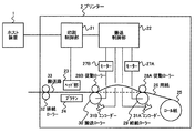
図1は、本発明を適用した搬送装置を備える印刷装置の実施の形態例に係る概略構成図である。図1に示すプリンター2が本実施の形態例に係る印刷装置であり、当該印刷装置は、印刷媒体の用紙26を給紙ローラー29(上流側ローラー)及び搬送ローラー30(下流側ローラー)で印刷位置に搬送して印刷処理を実行するが、各搬送動作中において、上記両ローラーによる駆動開始からの搬送量の差に従って、その搬送量差をなくすように給紙ローラー29の目標速度を変化させ、両ローラー間の用紙26の弛みを常に一定に保とうとするものである。 FIG. 1 is a schematic configuration diagram according to an embodiment of a printing apparatus including a transport device to which the present invention is applied. The printer 2 shown in FIG. 1 is a printing apparatus according to the present embodiment, and the printing apparatus prints a sheet 26 of a printing medium with a feed roller 29 (upstream roller) and a conveyance roller 30 (downstream roller). The printing process is performed by transporting to the position, and during each transport operation, the target speed of the paper feed roller 29 is changed so as to eliminate the transport amount difference according to the transport amount difference from the start of driving by the two rollers. The slack of the paper 26 between the two rollers is always kept constant.
更に、本プリンター2は、前回の搬送動作における両ローラーの加速中の駆動状況に基づいて、搬送ローラー30の起動タイミングを適切に遅らせ、更に、両ローラー間の用紙26の弛みを一定に保つようにする。 Further, the printer 2 appropriately delays the start timing of the transport roller 30 based on the driving state during acceleration of both rollers in the previous transport operation, and further keeps the slack of the paper 26 between the both rollers constant. To.
本プリンター2は、図1に示すように、コンピューターなどのホスト装置1からの指示を受けて印刷処理を実行する装置であり、ここでは、一例として、ロール紙25を用紙26として使用し、用紙26を搬送しながら連続的に印刷を実行する印刷装置である。
As shown in FIG. 1, the printer 2 is a device that executes a printing process in response to an instruction from a host device 1 such as a computer. Here, as an example, the printer 2 uses a
図1ではプリンター2の概略構成を模式的に示しているが、プリンター2は、印刷内容を制御し用紙26に印刷処理を実行する印刷系と用紙26の搬送を担う搬送系が備えられる。 In FIG. 1, the schematic configuration of the printer 2 is schematically illustrated. However, the printer 2 includes a printing system that controls printing contents and executes a printing process on the paper 26 and a transport system that transports the paper 26.
印刷系には、印刷制御部21が設けられ、当該印刷制御部21は、ホスト装置1からの印刷指示を受信し、当該指示に従ってヘッド部23に印刷命令を出すと共に搬送系の搬送制御部22に対して用紙26の搬送要求を出す。ヘッド部23では、当該印刷命令に従ってヘッド部23とプラテン24との間を所定速度で移動する用紙26に対して印刷処理を実行する。
The printing system is provided with a
搬送系では、図1に示されるように、印刷媒体の格納場所にロール紙25として保持される用紙26を、搬送路33に沿ってヘッド部23に搬送し、その後、排紙ローラー32を介してプリンター2から排出する搬送動作が実行される。
In the transport system, as shown in FIG. 1, the paper 26 held as the
そのヘッド部23への用紙搬送のために、それぞれ対応するモーター(27A及び27B)で駆動される給紙ローラー29(上流側ローラー)及び搬送ローラー30(下流側ローラー)が備えられる。当該両ローラーには、それぞれ、用紙26を挟んで対向する位置に従動ローラー(28A及び28B)が用紙26側に圧力を加えられた状態で配置される。
For paper conveyance to the
給紙ローラー29は、ロール紙25として保持される用紙26を搬送路33に供給する機能を有し、減速機を介して伝えられるモーター27Aのトルクによって回転し、従動ローラー28Aと共に押圧する用紙26との間の摩擦力によって用紙26を移動させる。
The paper feed roller 29 has a function of supplying the paper 26 held as the
搬送ローラー30は、給紙ローラー29によって供給された用紙26を印刷位置へ、すなわち、ヘッド部23の位置へ搬送する機能を有し、減速機を介して伝えられるモーター27Bのトルクによって回転し、従動ローラー28Bと共に押圧する用紙26との間の摩擦力によって用紙26を移動させる。
The transport roller 30 has a function of transporting the paper 26 supplied by the paper feed roller 29 to the printing position, that is, to the position of the
給紙ローラー29及び搬送ローラー30には、それぞれ、エンコーダー31A及び31Bが設けられ、それらによって検知される両ローラーの回転速度が搬送制御部22へ通知される。なお、これらエンコーダーは、それぞれ、給紙ローラー29及び搬送ローラー30の従動ローラー28A及び28Bに設置されるようにしてもよい。一般的に、駆動側ローラーの場合には、用紙26との間のすべりが発生したり、磨耗によるローラー径の経年変化も激しいため、エンコーダーを従動ローラー28A及び28Bに設置した場合の方がより正確な計測を行うことが可能である。 The paper feed roller 29 and the transport roller 30 are provided with encoders 31A and 31B, respectively, and the rotational speeds of both rollers detected by them are notified to the transport control unit 22. Note that these encoders may be installed on the driven rollers 28 </ b> A and 28 </ b> B of the paper feed roller 29 and the transport roller 30, respectively. In general, in the case of the driving roller, slippage between the paper 26 and the change in roller diameter over time due to wear is more severe. Therefore, it is better to install the encoder on the driven rollers 28A and 28B. Accurate measurement can be performed.
図1に示す搬送制御部22は、搬送系を制御する部分であり、印刷制御部21からの指示に基づいて用紙26の上記搬送動作を制御する。特に、給紙ローラー29及び搬送ローラー30の駆動・停止を制御して印刷位置への用紙26の良好な搬送を実行させる。この給紙ローラー29及び搬送ローラー30の駆動・停止制御に本プリンター2の特徴があり、その具体的内容については後述する。
The conveyance control unit 22 illustrated in FIG. 1 is a part that controls the conveyance system, and controls the conveyance operation of the paper 26 based on an instruction from the
搬送制御部22は、図示していないが、CPU、ROM、RAM、NVRAM(不揮発性メモリ)等で構成されており、搬送制御部22が実行する上記処理は、主にROMに格納されるプログラムに従ってCPUが動作することによって実行される。 Although not shown, the transport control unit 22 is configured by a CPU, a ROM, a RAM, an NVRAM (nonvolatile memory), and the like, and the processing executed by the transport control unit 22 is mainly a program stored in the ROM. It is executed by the CPU operating according to the above.
上記RAMには、処理に必要な各データが一時的に保持され、給紙ローラー29及び搬送ローラー30の駆動・停止制御に必要な上記搬送動作時の各駆動データ、後述するウェイト時間ΔTはここに記憶される。記憶される各駆動データには、給紙ローラー29及び搬送ローラー30の、駆動開始時刻、搬送速度、及び対応するモーター27のDuty値(ここではモーター27に供給される電流量)が含まれる。 Each data necessary for the processing is temporarily stored in the RAM, and each drive data during the transport operation necessary for driving / stopping control of the paper feed roller 29 and the transport roller 30 and a wait time ΔT described later are here. Is remembered. Each stored drive data includes the drive start time, the transport speed, and the corresponding duty value of the motor 27 (here, the amount of current supplied to the motor 27) of the paper feed roller 29 and the transport roller 30.
また、上記NVRAMには、上記ウェイト時間ΔTを決定するための関係情報、給紙ローラー29の目標速度を決定するための関係情報等が予め記憶されている。これらの関係情報については後述する。 Further, the NVRAM previously stores relation information for determining the wait time ΔT, relation information for determining the target speed of the paper feed roller 29, and the like. Such relation information will be described later.
なお、給紙ローラー29、搬送ローラー30、及び搬送制御部22を含む当該搬送系が本発明の搬送装置に相当する。 In addition, the said conveyance system containing the paper feed roller 29, the conveyance roller 30, and the conveyance control part 22 corresponds to the conveyance apparatus of this invention.
以上説明したような構成を有する本プリンター2では、用紙26の搬送制御に特徴があり、以下、その具体的な内容について説明する。 The printer 2 having the above-described configuration is characterized by the conveyance control of the paper 26, and the specific contents thereof will be described below.
前述のとおり、本プリンター2では、所定の(一定の)速度で搬送される用紙26に対して印刷処理を実行するので、基本的には、搬送制御部22は、印刷処理が開始されると、給紙ローラー29及び搬送ローラー30の搬送速度が当該所定速度に素早くなるように制御し、印刷処理が終了するまでその搬送速度を維持し、印刷処理が終了すると両ローラーを停止させる。かかる搬送動作、搬送処理が印刷処理を実行する度に繰り返し実行される。 As described above, since the printer 2 executes the printing process on the paper 26 that is conveyed at a predetermined (constant) speed, basically, the conveyance control unit 22 starts the printing process. The feeding speed of the paper feeding roller 29 and the feeding roller 30 is controlled so as to quickly reach the predetermined speed, and the feeding speed is maintained until the printing process is completed, and both rollers are stopped when the printing process is completed. The transport operation and the transport process are repeatedly executed every time the print process is executed.
また、用紙26を最初にセットする場合には、搬送制御部22は、給紙ローラー29と搬送ローラー30の間で用紙26に一定の弛み(例えば、図1に示すような弛み)ができるように両ローラーを制御して、用紙26を所定の位置まで搬送しておく。これは、前述したように、搬送ローラー30にバックテンションが作用しないようにするためのものであり、これにより搬送ローラー30から常に一定の速度で用紙26を印刷位置へ供給することができるようになる。 Further, when the paper 26 is set for the first time, the transport control unit 22 can perform a certain slack (for example, a slack as shown in FIG. 1) on the paper 26 between the paper feed roller 29 and the transport roller 30. Both rollers are controlled to convey the paper 26 to a predetermined position. As described above, this is to prevent back tension from acting on the transport roller 30, so that the paper 26 can always be supplied from the transport roller 30 to the printing position at a constant speed. Become.
ここで、給紙ローラー29は、上流側に位置するロール紙25から用紙26を引き出すための力をバックテンションとして受けることになるので、通常、用紙26の搬送中に搬送ローラー30よりも大きなバックテンションを受けることになる。
Here, the paper feed roller 29 receives a force for pulling out the paper 26 from the
従って、上記各搬送動作の開始時において、給紙ローラー29の方が上記所定速度に到達するまでに時間がかかる傾向にある。図2は、搬送動作における給紙ローラー29及び搬送ローラー30の挙動の一例を示した図である。当該図において、横軸は、駆動を開始してからの経過時間(T)を表し、縦軸は、各ローラーの搬送速度(V)を表している。そして、グラフの曲線Aが給紙ローラー29の挙動を示し、曲線Bが搬送ローラー30の挙動を示している。 Accordingly, at the start of each of the transport operations, the paper feed roller 29 tends to take more time to reach the predetermined speed. FIG. 2 is a diagram illustrating an example of the behavior of the paper feed roller 29 and the transport roller 30 in the transport operation. In the figure, the horizontal axis represents the elapsed time (T) from the start of driving, and the vertical axis represents the conveyance speed (V) of each roller. A curve A in the graph shows the behavior of the paper feed roller 29, and a curve B shows the behavior of the transport roller 30.
上述のとおり、搬送ローラー30と比べて給紙ローラー29の方により大きなバックテンションが作用するので、図2に示すとおり、目標とする上記所定速度(Vt)に達するまでの搬送速度の立ち上がりが給紙ローラー29(曲線A)の方が緩やかとなってしまう。そのため、両ローラーが上記所定速度に達するまでの両ローラーの用紙搬送量に差が生じることにある。図2に示す例では、曲線Bと曲線Aの間にできた面積分の搬送量差(ΔL)が生じることになる。 As described above, since a larger back tension acts on the paper feed roller 29 than on the transport roller 30, the rising of the transport speed until the target predetermined speed (Vt) is reached as shown in FIG. The paper roller 29 (curve A) becomes gentler. Therefore, there is a difference in the amount of paper transported by both rollers until the both rollers reach the predetermined speed. In the example illustrated in FIG. 2, a conveyance amount difference (ΔL) corresponding to the area formed between the curve B and the curve A is generated.
従って、上記搬送動作の開始時に両ローラーを同時に起動すると、両ローラーが所定速度Vtに達し同じ搬送量で制御されるまでに、搬送ローラー30の方が当該搬送量差(ΔL)分多く搬送することになる。これは、上述した用紙26の弛みを減らしてしまうことであり、その搬送量差によっては弛みがなくなってしまう虞もある。そこで、本プリンター2の搬送制御部22では、この起動開始時の(加速中の)搬送量差を解消することを一つの目的とする。 Therefore, if both rollers are activated simultaneously at the start of the transport operation, the transport roller 30 transports more by the transport amount difference (ΔL) until both rollers reach the predetermined speed Vt and are controlled with the same transport amount. It will be. This is to reduce the slack of the paper 26 described above, and there is a possibility that the slack may be eliminated depending on the difference in the transport amount. Therefore, one object of the transport control unit 22 of the printer 2 is to eliminate the transport amount difference (during acceleration) at the start of activation.
また、所定速度Vtに達した以降(図2のCで示す期間)においても、上述したように、特にその期間が長い場合には、給紙ローラー29と搬送ローラー30の搬送量に差が生じる場合がある。この期間では、基本的には、両ローラーによる搬送速度の目標値を所定速度Vtにして制御を実行するが、ローラーにかかる負荷変動によって搬送速度が所定速度Vtから外れた場合には、そのことによる搬送量の差は考慮されず、搬送速度を所定速度Vtに戻そうとする制御が行われるので、上記搬送量差が生じる虞がある。 Further, even after reaching the predetermined speed Vt (a period indicated by C in FIG. 2), as described above, particularly when the period is long, a difference occurs in the transport amount between the paper feed roller 29 and the transport roller 30. There is a case. During this period, basically, the control is executed with the target value of the transport speed by both rollers set to the predetermined speed Vt. However, if the transport speed deviates from the predetermined speed Vt due to the load fluctuation applied to the rollers, this is the case. The difference in the transport amount due to the above is not considered, and control is performed to return the transport speed to the predetermined speed Vt. Therefore, the transport amount difference may occur.
当該搬送量差は、やはり、上述した一定の弛みを変動させてしまうものであり好ましくない。そこで、当該定速時の搬送量差を解消することも当該搬送制御部22による制御の一つの目的である。 The difference in the transport amount is not preferable because it changes the above-described constant slack. Therefore, eliminating the transport amount difference at the constant speed is one purpose of the control by the transport control unit 22.
本搬送制御部22では、以上の目的を達成し、上記初期状態で生成した弛みを上記各搬送動作中においてほぼ一定に保てるような制御を実行する。以下、その具体的な制御内容を説明する。 The transport control unit 22 performs control so as to achieve the above object and keep the slack generated in the initial state substantially constant during the transport operations. The specific control contents will be described below.
図3は、搬送制御部22が実行する処理の手順を例示したフローチャートである。以下、図3に従って上記搬送動作についての制御内容を説明する。なお、当該制御における一つの特徴は、上述した駆動開始時の搬送量差を搬送ローラー30の起動タイミングを遅らせることによって解消するというものであり、その起動タイミングを、ロール紙25の残量などその時の装置状況をよく表す、前回の搬送動作時における駆動データに基づいて決定しようとするものである。ここで、当該駆動データとして、給紙ローラー29及び搬送ローラー30の立ち上がり時間差(上記所定速度Vtに到達するまでの時間差)、給紙ローラー29及び搬送ローラー30の立ち上がるまでの搬送量差(ΔL)、及び、上記所定速度に達した後の給紙ローラー29及び搬送ローラー30の各モーター27のDuty値差(ΔD)、をそれぞれ用いた方法が実行され得る。
FIG. 3 is a flowchart illustrating a procedure of processing executed by the transport control unit 22. Hereinafter, the control content of the above-described transport operation will be described with reference to FIG. One feature of the control is that the above-described difference in the conveyance amount at the start of driving is eliminated by delaying the activation timing of the conveyance roller 30, and the activation timing is determined at that time, such as the remaining amount of the
当該制御の更なる特徴は、上記起動タイミング制御で解消し切れなかった搬送量差及び上述した定速搬送時に発生する搬送量差を解消すべく、その時点で検知される、その搬送動作開始からの両ローラーの搬送量差に従って、定速搬送時における給紙ローラー29の目標速度を変更する、というものである。 A further feature of the control is that from the start of the transport operation, which is detected at that time, in order to eliminate the transport amount difference that could not be completely eliminated by the start timing control and the transport amount difference that occurs during the constant speed transport described above. The target speed of the paper feed roller 29 during constant speed conveyance is changed according to the difference in conveyance amount between the two rollers.
各搬送動作において、まず、搬送制御部22は、印刷制御部21から用紙の搬送開始指示を受信すると(ステップS1)、前述したRAMに記憶されているウェイト時間ΔTの値を取得する(ステップS2)。このウェイト時間ΔTは、上述した、搬送ローラー30の起動タイミングを遅らせるための待ち時間であり、各搬送動作の終了後に決定し、次の搬送動作のために保持されている情報である。すなわち、前回の搬送動作時に決定された値である。具体的な決定方法については後述する。なお、当該プリンター2の起動後、最初の搬送動作である場合には、上記NVRAMに保持される予め定められたデフォルト値を取得する。また、各搬送動作時に決定したウェイト時間ΔTの値を上記NVRAMに記憶して、そこから取得するようにしても良い。 In each transport operation, first, when the transport control unit 22 receives a paper transport start instruction from the print control unit 21 (step S1), the transport control unit 22 acquires the value of the wait time ΔT stored in the RAM (step S2). ). This wait time ΔT is a waiting time for delaying the start timing of the transport roller 30 described above, and is information that is determined after the end of each transport operation and is held for the next transport operation. That is, the value determined during the previous transport operation. A specific determination method will be described later. Note that in the case of the first transport operation after the printer 2 is activated, a predetermined default value held in the NVRAM is acquired. Further, the value of the wait time ΔT determined during each transport operation may be stored in the NVRAM and obtained from there.
また、搬送制御部22は、上記指示の後、給紙ローラー29の駆動を開始させる(ステップS3)。すなわち、モーター27Aを起動させ、その後、給紙ローラー29における搬送速度が目標とする上記所定速度Vtになるように制御を継続する。なお、搬送制御部22は、給紙ローラー29及び搬送ローラー30の駆動制御を、エンコーダー31A及び31Bの検知結果に基づくPID制御で行う。
Further, after the above instruction, the transport control unit 22 starts driving the paper feed roller 29 (step S3). That is, the
次に、搬送制御部22は、当該給紙ローラー29の駆動開始後、上記取得したウェイト時間ΔTが経過するのを待って(ステップS4)、搬送ローラー30の駆動を開始させる(ステップS5)。すなわち、モーター27Bを起動させ、その後、搬送ローラー30における搬送速度が目標とする上記所定速度になるように制御を継続する。 Next, after the driving of the paper feed roller 29 is started, the transport control unit 22 waits for the acquired wait time ΔT to elapse (step S4), and starts driving of the transport roller 30 (step S5). That is, the motor 27B is activated, and then the control is continued so that the transport speed of the transport roller 30 becomes the target predetermined speed.
このように、搬送ローラー30の起動タイミングをウェイト時間ΔTだけ遅らせることにより、上述した起動開始時における搬送量差がほぼ解消される。その具体的な内容については後述する。 In this way, by delaying the start timing of the transport roller 30 by the wait time ΔT, the above-described transport amount difference at the start of the start is substantially eliminated. The specific contents will be described later.
その後、給紙ローラー29及び搬送ローラー30が上記所定速度Vtに達すると、両ローラーについて定速駆動の制御を実行する(ステップS6)。当該制御において、搬送ローラー30については、常に一定の速度で用紙26を印刷位置へ供給することが求められるので、上記所定速度Vtを目標速度としたPID制御を実行する。 Thereafter, when the paper feed roller 29 and the transport roller 30 reach the predetermined speed Vt, the constant speed drive control is executed for both rollers (step S6). In the control, since the transport roller 30 is always required to supply the paper 26 to the printing position at a constant speed, PID control is performed with the predetermined speed Vt as a target speed.
一方、給紙ローラー29については、基本的には搬送ローラー30と同様に上記所定速度Vtを目標速度としたPID制御を実行するが、当該搬送動作の開始からの両ローラーの搬送量に差(ΔL)がある場合には、その搬送量差がゼロになるように、PID制御において目標速度を上記所定速度Vtから所定量ずらした制御を行う。すなわち、給紙ローラー29による上記搬送量の方が多い場合には、目標速度を上記所定速度Vtよりも小さい値とし、その逆の場合には、目標速度を上記所定速度Vtよりも大きい値としたPID制御を行う。 On the other hand, for the paper feed roller 29, basically, PID control is executed with the predetermined speed Vt as a target speed in the same manner as the transport roller 30, but the difference between the transport amounts of both rollers from the start of the transport operation ( If there is [Delta] L), control is performed in which the target speed is shifted from the predetermined speed Vt by a predetermined amount in the PID control so that the transport amount difference becomes zero. That is, when the transport amount by the paper feed roller 29 is larger, the target speed is set to a value smaller than the predetermined speed Vt, and in the opposite case, the target speed is set to a value larger than the predetermined speed Vt. PID control is performed.
具体的には、上述したNVRAMに予め記憶された、当該目標速度を決定するための関係情報Gを用いて、上記所定速度Vtからの変化量ΔVを、ΔV=G×ΔLなる式で求め、その変化量ΔVを用いて、その時点のPID制御の目標である、目標速度(=Vt+ΔV)を決定する。 Specifically, using the relationship information G for determining the target speed stored in advance in the above-described NVRAM, a change amount ΔV from the predetermined speed Vt is obtained by an equation: ΔV = G × ΔL, Using the change amount ΔV, the target speed (= Vt + ΔV), which is the target of the PID control at that time, is determined.
図4は、当該定速搬送時の制御を説明するための図である。図4には、定速搬送時の給紙ローラー29(図中の線A)及び搬送ローラー30(図中のB)による搬送速度V(図4の(A))、及び、両ローラーの上記搬送量差ΔL(図4の(B)、線AA)を経時的に例示している。ここでは、時刻T01から時刻T03の期間付近で給紙ローラー29にかかる負荷が急に脈動し、それによってPID制御による給紙ローラー29の速度が変動した場合を想定している。なお、搬送ローラー30については、上記所定速度Vtで概ね一定に制御されている。 FIG. 4 is a diagram for explaining the control during the constant speed conveyance. In FIG. 4, the conveyance speed V ((A) of FIG. 4) by the paper feed roller 29 (line A in the figure) and the conveyance roller 30 (B in the figure) during constant speed conveyance, and the above of both rollers The conveyance amount difference ΔL (FIG. 4B, line AA) is illustrated over time. Here, it is assumed that the load applied to the paper feed roller 29 suddenly pulsates in the vicinity of the period from time T01 to time T03, thereby changing the speed of the paper feed roller 29 by PID control. The transport roller 30 is controlled to be substantially constant at the predetermined speed Vt.
この場合、時刻T02以降、給紙ローラー29による搬送量が搬送ローラー30の搬送量よりも多くなってしまうので、上述した給紙ローラー29の目標速度設定により、給紙ローラー29については、適宜、上記所定速度Vtよりも遅い目標速度が設定されてPID制御がなされる。そして、上記脈動により時刻T03において最高に達した速度から徐々に速度が降下し、時刻T04以降は、実際の速度が上記所定速度Vtよりも遅くなるので、線AAに示されるように、搬送量差ΔLが減少し始め、その差がゼロになると(時刻T05)給紙ローラー29の目標速度が上記所定速度Vtに戻るように制御される。 In this case, after time T02, the transport amount by the paper feed roller 29 becomes larger than the transport amount of the transport roller 30, so that the paper feed roller 29 is appropriately set according to the target speed setting of the paper feed roller 29 described above. A target speed slower than the predetermined speed Vt is set and PID control is performed. Then, the speed gradually decreases from the speed that reached the maximum at time T03 due to the pulsation, and after time T04, the actual speed becomes slower than the predetermined speed Vt. Therefore, as shown by line AA, the conveyance amount When the difference ΔL starts to decrease and becomes zero (time T05), the target speed of the paper feed roller 29 is controlled to return to the predetermined speed Vt.
なお、単に目標速度を上記所定速度Vtにする制御では、負荷の変動が無ければ、給紙ローラー29の速度は、時刻T03以降、徐々に降下してVtに近づいていくことになり、搬送量差ΔLがゼロになることなく制御が継続されることになる。 In the control for simply setting the target speed to the predetermined speed Vt, if there is no load fluctuation, the speed of the paper feed roller 29 gradually decreases and approaches Vt after time T03, and the carry amount Control is continued without the difference ΔL becoming zero.
このような定速搬送時の制御により、上記ウェイト時間ΔTによる制御で解消し切れなかった加速中に発生する搬送量差、及び、定速搬送時に発生する搬送量差をリアルタイムの制御で解消することができる。なお、上記搬送量差は、各エンコーダー31A及び31Bによって検知された値から求められる。 With such control during constant speed conveyance, the conveyance amount difference that occurs during acceleration and the conveyance amount difference that occurs during constant speed conveyance that could not be completely eliminated by the control based on the wait time ΔT and real time control are eliminated. be able to. In addition, the said conveyance amount difference is calculated | required from the value detected by each encoder 31A and 31B.
なお、上述した関係情報G(ここでは、定数)は、予め実験により適切な値を決定して記憶しておく。また、この関係情報Gは、用紙26の材質や厚さなど用紙種類によって異なるので、用紙種類毎に適切な値を決定して識別可能にNVRAMに記憶しておくことが好ましい。この場合には、印刷制御部21から搬送開始の指示を受ける際(S1)などに、用紙種類の情報を受信し、その情報に基づいて相応した上記関係情報を用いて制御を行う。 It should be noted that the above-described relation information G (here, a constant) is determined and stored in advance by an appropriate experiment. Further, since the relationship information G differs depending on the paper type such as the material and thickness of the paper 26, it is preferable to determine an appropriate value for each paper type and store it in the NVRAM so that it can be identified. In this case, when receiving an instruction to start conveyance from the print control unit 21 (S1) or the like, information on the paper type is received, and control is performed using the corresponding relationship information based on the information.
また、関係情報Gは、給紙ローラー29に作用するバックテンションの大きさによって変えることが好ましく、そのバックテンションに影響を及ぼすロール紙25の径によって関係情報Gを補正するようにしても良い。すなわち、関係情報Gをロール紙径を変数とする関数で表現しても良い。この場合、制御時のロール紙径は、プリンター2に設けられたタッチセンサーや反射式センサーで直接計測する方法、ロール紙25の取付け後の回転数やロール紙25の取付け後のエンコーダー(31A、31B)の検知情報(累計搬送量)に基づいて推定する方法などにより取得することができる。
The relationship information G is preferably changed according to the magnitude of the back tension acting on the paper feed roller 29, and the relationship information G may be corrected by the diameter of the
なお、目標速度を決定するための情報(搬送量差ΔL)と目標速度からの変化量(ΔV)の関係を線形としたが、それらの関係を ΔV=f(ΔL)なる線形でない関数fとしてもよい。また、弛み量をより精度よく制御する場合には、変化量ΔVを、上述した比例制御(偏差×ゲインG)だけではなく、積分制御(偏差の積分×ゲインGi)や微分制御(偏差の微分×ゲインGd)を考慮して求めればよい。これらの場合にも、関数fやPID制御方法(G,Gi,Gd,ΔVの計算式)を事前に定め、関係情報として記録しておく。 Although the relationship between the information for determining the target speed (conveyance amount difference ΔL) and the amount of change (ΔV) from the target speed is linear, the relationship is expressed as a non-linear function f such that ΔV = f (ΔL). Also good. In order to control the amount of slack more accurately, the change amount ΔV is not limited to the above-described proportional control (deviation × gain G), but also integrated control (deviation integral × gain Gi) or differential control (deviation differentiation). X Gain Gd) may be taken into consideration. Also in these cases, the function f and the PID control method (G, Gi, Gd, ΔV calculation formulas) are determined in advance and recorded as relation information.
以上説明した定速搬送の後、印刷制御部21から搬送の停止指示を受信すると(ステップS7)、搬送制御部22は、給紙ローラー29及び搬送ローラー30の駆動を停止させる制御を行う(ステップS8)。当該制御では、両ローラーについて、それぞれ、単に素早く速度をゼロにする制御を行ってもよいが、好ましくは、今回の搬送動作における両ローラーの搬送量が同じになるように各ローラーを停止させる制御を実行する。これにより、当該搬送動作の開始時における給紙ローラー29・搬送ローラー30間の用紙26の弛みが更に確実に保持される。
When the conveyance stop instruction is received from the
このようにして、両ローラーが停止されて今回の搬送動作が終了すると、搬送制御部22は、今回の搬送動作における給紙ローラー29及び搬送ローラー30の駆動状況から、次の搬送動作における上記ウェイト時間ΔTを決定し、その値を上記RAMに、前に保持していた値を削除して、記憶する(ステップS9)。 In this way, when both rollers are stopped and the current transport operation is completed, the transport control unit 22 determines the weight in the next transport operation from the driving status of the paper feed roller 29 and the transport roller 30 in the current transport operation. The time ΔT is determined, and the value stored in the RAM is deleted and stored (step S9).
当該ウェイト時間ΔTは、駆動開始時における給紙ローラー29と搬送ローラー30の挙動の差による搬送量の相違を克服するためのものであるので、両ローラーの駆動開始時の挙動からこのウェイト時間ΔTを決定する方法を取ることができる。具体的には、上述したとおり、一つの方法として、給紙ローラー29及び搬送ローラー30の立ち上がり時間差から求める。 The wait time ΔT is for overcoming the difference in transport amount due to the difference in behavior of the paper feed roller 29 and the transport roller 30 at the start of driving. Therefore, the wait time ΔT is determined from the behavior at the start of driving of both rollers. Can take a way to determine. Specifically, as described above, as one method, it is obtained from the rise time difference between the paper feed roller 29 and the transport roller 30.
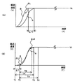
図5は、ウェイト時間ΔTを説明するための図である。図5の(A)は、図2に示したグラフと同様、給紙ローラー29と搬送ローラー30が同時に駆動開始をした場合の経時的な速度変化を示しており、上記立ち上がり時間差は、ここではΔT1に相当する。すなわち、各ローラーが駆動を開始してから目標の所定速度Vtに達するまでの所要時間差である。 FIG. 5 is a diagram for explaining the wait time ΔT. FIG. 5A shows the change in speed over time when the paper feed roller 29 and the transport roller 30 start driving at the same time as in the graph shown in FIG. It corresponds to ΔT1. That is, it is a difference in required time from the start of driving of each roller until reaching the target predetermined speed Vt.
図5の(B)は、図3に基づいて説明した本プリンター2における制御を実行した場合の、給紙ローラー29と搬送ローラー30の経時的な搬送速度変化を示している。曲線Bで示される搬送ローラー30の駆動開始が、前述の説明のとおり、曲線Aで示される給紙ローラー29の駆動開始よりもウェイト時間ΔTだけ遅らされている。これにより、2つのローラーが両方とも目標の所定速度Vtに達した時点(図中のT3)までに、両ローラーがそれぞれ搬送する量が概ね同じとなり(図中のΔL1とΔL2の面積がほぼ同じとなり)、当該搬送動作中に上記用紙26の弛みがほぼ一定に保たれることになる。 FIG. 5B shows a change in conveyance speed over time of the paper feed roller 29 and the conveyance roller 30 when the control in the printer 2 described with reference to FIG. 3 is executed. As described above, the driving start of the transport roller 30 indicated by the curve B is delayed by the wait time ΔT from the driving start of the paper feed roller 29 indicated by the curve A. As a result, by the time when both of the two rollers reach the target predetermined speed Vt (T3 in the figure), the amounts conveyed by both rollers are substantially the same (the areas of ΔL1 and ΔL2 in the figure are substantially the same). The slack of the paper 26 is kept substantially constant during the transport operation.
上述した立ち上がり時間差ΔT1とウェイト時間ΔTは概ね比例的な関係にあるといえるので、予め実験によりΔT=k1×ΔT1の比例係数k1を決定しておき、その情報を上述した関係情報としてNVRAMに記憶しておく。従って、当該方法では、給紙ローラー29及び搬送ローラー30について、それぞれ、駆動開始から上記所定速度到達までの時間を求め、図5の(B)に示す例では、TAとTBを求め、それらの差からΔT1を算出し、上記関係情報である比例係数k1を用いて、ΔT=k1×ΔT1の関係からウェイト時間ΔTを決定する。 Since it can be said that the above-described rise time difference ΔT1 and wait time ΔT have a substantially proportional relationship, a proportional coefficient k1 of ΔT = k1 × ΔT1 is determined in advance by experiment, and the information is stored in the NVRAM as the above-described relationship information. Keep it. Therefore, in this method, for the paper feed roller 29 and the transport roller 30, the time from the start of driving to the arrival of the predetermined speed is obtained, and in the example shown in FIG. 5B, TA and TB are obtained. ΔT1 is calculated from the difference, and the wait time ΔT is determined from the relationship ΔT = k1 × ΔT1 using the proportionality coefficient k1 which is the relationship information.
なお、上述したRAMに記憶される各駆動データは、上述した定速搬送時の制御やこのウェイト時間ΔTの決定に用いるが、これらのデータは搬送制御部22が適宜取得して記憶する。また、給紙ローラー29及び搬送ローラー30の搬送速度及び対応するモーター27のDuty値(ここではモーター27に供給される電流量)は、所定の時間間隔で記憶される。 The drive data stored in the above-described RAM is used for the above-described control during the constant-speed transfer and the determination of the wait time ΔT. The transfer control unit 22 appropriately acquires and stores these data. Further, the transport speed of the paper feed roller 29 and the transport roller 30 and the corresponding duty value of the motor 27 (here, the amount of current supplied to the motor 27) are stored at predetermined time intervals.
二つ目の方法は、給紙ローラー29及び搬送ローラー30の立ち上がるまでの搬送量差ΔLから決定する方法である。この場合にも、当該搬送量差ΔLとウェイト時間ΔTは概ね比例的な関係にあるといえるので、予め実験によりΔT=k2×ΔLの比例係数k2を決定しておき、その情報を上述した関係情報としてNVRAMに記憶しておく。従って、当該方法では、給紙ローラー29及び搬送ローラー30について、それぞれ、駆動開始から、給紙ローラー29の駆動開始から上記所定速度到達までの時間(図5の(B)に示すTA)に用紙26を搬送した量を求め、それらの差からΔLを算出し、上記関係情報である比例係数k2を用いて、ΔT=k2×ΔLの関係からウェイト時間ΔTを決定する。 The second method is a method of determining from the conveyance amount difference ΔL until the paper feed roller 29 and the conveyance roller 30 rise. Also in this case, since it can be said that the conveyance amount difference ΔL and the wait time ΔT have a substantially proportional relationship, a proportional coefficient k2 of ΔT = k2 × ΔL is determined in advance by experiment, and the information is related to the relationship described above. Information is stored in NVRAM as information. Therefore, in this method, the paper feed roller 29 and the transport roller 30 are each in the time from the start of driving until the predetermined speed is reached after the start of driving of the paper feed roller 29 (TA shown in FIG. 5B). 26 is obtained, ΔL is calculated from the difference between them, and the wait time ΔT is determined from the relationship of ΔT = k2 × ΔL using the proportionality coefficient k2 which is the relationship information.
図5の(B)に示す例においては、給紙ローラー29の加速中の上記搬送量は時刻T1からT3までの搬送量であり、搬送ローラー30の加速中の上記搬送量はT2からT4までの搬送量となって、これら搬送量の差からΔLが算出される。 In the example shown in FIG. 5B, the conveyance amount during acceleration of the paper feed roller 29 is the conveyance amount from time T1 to T3, and the conveyance amount during acceleration of the conveyance roller 30 is from T2 to T4. ΔL is calculated from the difference between these carry amounts.
次に、三つ目の方法について説明する。当該方法は、駆動開始時における給紙ローラー29と搬送ローラー30の挙動の差を、上記所定速度Vtに達した後の給紙ローラー29及び搬送ローラー30の各モーター27のDuty値差ΔDで計ろうとするものである。すなわち、上記Duty値差ΔDからウェイト時間ΔTを決定する。 Next, the third method will be described. In this method, the difference in behavior between the paper feed roller 29 and the transport roller 30 at the start of driving is measured by the duty value difference ΔD of each motor 27 of the paper feed roller 29 and the transport roller 30 after reaching the predetermined speed Vt. It is something to try. That is, the wait time ΔT is determined from the duty value difference ΔD.
図6は、モーター27A及び27BのDuty値の一例を経時的に示した図である。Duty値は、各モーター27に供給される電流量を相対値で示したものであり、この値が大きいほどローラーに加えるべき力が大きいことを示す。
FIG. 6 is a diagram showing an example of the duty values of the
図6では、給紙ローラー29と搬送ローラー30の駆動開始からのモーター27A(曲線A)及び27B(曲線B)のDuty値を示している。通常、起動時には大きな力が必要であるので、Duty値は図6に示す山状となり、目標速度に達した以降はほぼ一定したDuty値となる。
In FIG. 6, the duty values of the
同じ目標速度に制御しようとする二つのローラーについて、このDuty値がより大きいということは、駆動の負荷が(駆動に必要な動力が)より大きいことを意味し、すなわち、給紙ローラー29へ作用するバックテンションがより大きいことを示している。従って、Duty値差により駆動開始時の前述した立ち上がりの遅れを計ることが可能である。そこで、この方法では、Duty値差からウェイト時間ΔTを決定する。また、用いるDuty値差は、駆動開始時の制御においては、Duty値が大きく変動し安定していないため、上記所定速度に達成した以降の安定した時間帯(例えば、図6のPに示す時間帯)でのDuty値差ΔDを用いる。 For two rollers to be controlled to the same target speed, a larger duty value means that the driving load (the power required for driving) is larger, that is, it acts on the feeding roller 29. This indicates that the back tension is greater. Therefore, it is possible to measure the above-described rise delay at the start of driving based on the duty value difference. Therefore, in this method, the wait time ΔT is determined from the duty value difference. Further, the duty value difference to be used is not stable because the duty value fluctuates greatly in the control at the start of driving. The duty value difference ΔD in the band) is used.
この場合にも、当該Duty値差ΔDとウェイト時間ΔTは概ね比例的な関係にあるといえるので、予め実験によりΔT=k3×ΔDの比例係数k3を決定しておき、その情報を上述した関係情報としてNVRAMに記憶しておく。従って、当該方法では、給紙ローラー29及び搬送ローラー30が上記所定速度に到達した以降の各ローラーの代表的なDuty値を求め、それらの差からΔDを算出し、上記関係情報である比例係数k3を用いて、ΔT=k3×ΔDの関係からウェイト時間ΔTを決定する。 Also in this case, it can be said that the duty value difference ΔD and the wait time ΔT are in a substantially proportional relationship. Therefore, a proportional coefficient k3 of ΔT = k3 × ΔD is determined in advance by experiment, and the information is related to the relationship described above. Information is stored in NVRAM as information. Therefore, in this method, the representative duty value of each roller after the paper feed roller 29 and the transport roller 30 reach the predetermined speed is obtained, ΔD is calculated from the difference therebetween, and the proportionality coefficient that is the relation information is obtained. Using k3, the wait time ΔT is determined from the relationship ΔT = k3 × ΔD.
なお、上記代表的なDuty値は、予め設定した時間内で検知される複数のDuty値の平均値とすることができる。 The representative duty value can be an average value of a plurality of duty values detected within a preset time.
なお、これら3つの方法において、ここでは、ウェイト時間を決定するための情報(ΔT1、ΔL、ΔD、これらを総称してΔX)とウェイト時間ΔTの関係を線形としたが、それらの関係をΔT=f(ΔX)なる線形でない関数fとしてもよい。この場合にも関数fを事前に定め、関係情報として記録しておく。 In these three methods, the relationship between the information for determining the wait time (ΔT1, ΔL, ΔD, collectively referred to as ΔX) and the wait time ΔT is linear. It may be a non-linear function f = f (ΔX). Also in this case, the function f is determined in advance and recorded as related information.
このようにして、ウェイト時間ΔTを決定し、それを上記RAMに記憶し、この値を更新すると(ステップS9)、当該搬送動作についての一連の制御処理が終了し、以降、同様の処理を繰り返し実行する。 In this way, the wait time ΔT is determined, stored in the RAM, and when this value is updated (step S9), a series of control processing for the transport operation is completed, and thereafter the same processing is repeated. Run.
なお、上述したウェイト時間を決定するための情報(ΔT1、ΔL、ΔD)とウェイト時間の関係は、用紙26の種類等によって異なるため、本プリンター2で使用される各用紙毎に上記関係情報を用意しておくようにしてもよい。 It should be noted that the relationship between the information for determining the wait time (ΔT1, ΔL, ΔD) and the wait time differs depending on the type of the paper 26 and the like. You may make it prepare.
また、上記実施形態では、用紙26の弛みを一定に保つために、ウェイト時間ΔTによる制御と給紙ローラー29の目標速度を変更する制御の両方を実行するようにしたが、後者だけを実行するようにしてもよい。 In the above embodiment, in order to keep the slack of the paper 26 constant, both the control by the wait time ΔT and the control to change the target speed of the paper feed roller 29 are executed, but only the latter is executed. You may do it.
また、上記実施形態の制御に、更に、たるみセンサーを用いた危険回避のための制御を追加する構成としてもよい。図7は、当該構成におけるたるみセンサー34の一例を示した概略図である。当該構成は、図1に示した構成に図7に示すようなたるみセンサー34を加えたものであり、当該たるみセンサー34により、給紙ローラー29と搬送ローラー30の間の用紙26の弛みが許容範囲を越えないように制御するものである。従って、たるみセンサー34は当該弛みの上限値(UL)と下限値(LL)を検知できる機能を有する。 Moreover, it is good also as a structure which adds the control for danger avoidance which used the slack sensor further to the control of the said embodiment. FIG. 7 is a schematic view showing an example of the sag sensor 34 in the configuration. This configuration is obtained by adding a sag sensor 34 as shown in FIG. 7 to the configuration shown in FIG. 1, and the sag sensor 34 allows slack of the paper 26 between the paper feed roller 29 and the transport roller 30. It is controlled so as not to exceed the range. Accordingly, the sag sensor 34 has a function of detecting the upper limit value (UL) and the lower limit value (LL) of the slackness.
当該弛みの上限値とは、それ以上弛みの量が増えると搬送路33の部材に接触するなど搬送上の不具合が発生する虞がある限界値であり、図7では用紙26が上昇できる限界位置を表す。また、上記弛みの下限値とは、弛みの量がそれ以下に減ると、搬送ローラー30へのバックテンションが発生してしまう虞がある限界値であり、図7では用紙26が下降できる限界位置を表す。
The upper limit value of the slackness is a limit value that may cause a trouble in conveyance such as contact with a member of the
図7のたるみセンサー34は、常に用紙26に軽く触れており用紙26の弛みに応じて上下に移動する先端部と、その上下動に従って支点を中心に回動する棒状部材と、その棒状部材の先端部とは反対側の端部の移動量を検知する検知部等から構成され、その検知部が上記上限値(UL)又は上記下限値(LL)に達した事を検知した場合には、そのことが搬送制御部22に通知される。 The slack sensor 34 in FIG. 7 always touches the paper 26 lightly and moves up and down according to the slack of the paper 26, a rod-like member that rotates around a fulcrum according to its vertical movement, It is composed of a detection unit that detects the amount of movement of the end opposite to the tip, and when the detection unit detects that the upper limit (UL) or the lower limit (LL) has been reached, This is notified to the conveyance control unit 22.
なお、図7に示すたるみセンサー34は一例であって、上記弛みの上下限値を検知できるものであれば光センサーやタッチセンサーなど異なる構成のセンサーをたるみセンサーとして用いることができる。 Note that the sag sensor 34 shown in FIG. 7 is an example, and a sensor having a different configuration such as an optical sensor or a touch sensor can be used as the sag sensor as long as it can detect the upper and lower limits of the slack.
上述した実施形態の制御では、前回の搬送動作時の駆動状態に基づく制御(ウェイト時間による制御)及びその時点の上記搬送量差に基づくリアルタイム制御を行って、その搬送動作開始時の上記弛み量を保持するが、エンコーダー31A、31Bの計測誤差等が累積して、一定に保たれるはずの上記弛みが徐々に増加又は減少していく可能性もある。また、何らかの故障によって、急に制御が正常に行われない事態が発生し上記弛み量が急激に変化する虞もある。 In the control of the above-described embodiment, control based on the driving state at the previous transport operation (control by wait time) and real-time control based on the transport amount difference at that time are performed, and the amount of slack at the start of the transport operation However, there is a possibility that the measurement errors of the encoders 31A and 31B accumulate and the above-mentioned slack that should be kept constant gradually increases or decreases. In addition, there is a possibility that a situation in which the control is not normally performed suddenly due to some failure and the amount of slackness changes abruptly.
当該たるみセンサーを追加する構成は、このような事態に対する危険回避を目的とするものであり、搬送制御部22は、上述した実施形態での制御に加え、たるみセンサー34が上記上限値(UL)又は上記下限値(LL)に達した事を検知した場合に、搬送動作を停止させる、又は、上記搬送量差に基づくリアルタイム制御(給紙ローラー29の目標速度を変更する制御)においてその搬送量差ΔLをリセットする、という制御を実行する。 The configuration in which the sag sensor is added is for the purpose of avoiding danger against such a situation. In addition to the control in the above-described embodiment, the sag sensor 34 has the upper limit (UL). Alternatively, when it is detected that the lower limit value (LL) has been reached, the transport operation is stopped, or the transport amount in real-time control (control to change the target speed of the paper feed roller 29) based on the transport amount difference. The control of resetting the difference ΔL is executed.
前者の場合には、搬送動作が直ぐに停止されるので、上記弛みが増加しすぎて用紙ジャムを起こしてしまうことや上記弛みが減少しすぎて搬送ローラー30にバックテンションが作用し不良な印刷を実施してしまうこと等を回避することができる。 In the former case, since the transport operation is immediately stopped, the slack increases too much, causing a paper jam, or the slack decreases too much, and the back tension acts on the transport roller 30 to perform poor printing. This can be avoided.
後者の場合には、上記上限値又は上記下限値に達したことが検知された際に、その時点の上記搬送量差ΔLを、上記上限値又は上記下限値に対して予め定められているリセット値に変更し、それ以降は、そのリセット値をそれ以降の搬送量差で更新した値として、制御を行う。すなわち、このようにリセットされた搬送量差ΔLに従って、上述した給紙ローラー29の目標速度を変更する制御を実行する。なお、上記リセット値は、上記初期状態で生成する一定に保つべき弛みの場合に両ローラー(給紙ローラー29と搬送ローラー30)間に存在する用紙26の長さと、上記上限値又は上記下限値に達した際に両ローラー間に存在する用紙26の長さとの差分であり、予め定められた値が上記NVRAMに記憶される。 In the latter case, when it is detected that the upper limit value or the lower limit value has been reached, the transport amount difference ΔL at that time is reset in advance with respect to the upper limit value or the lower limit value. Thereafter, the control is performed with the reset value updated with the subsequent transport amount difference. That is, the control for changing the target speed of the paper feed roller 29 described above is executed according to the transport amount difference ΔL thus reset. The reset value includes the length of the sheet 26 existing between the two rollers (the feed roller 29 and the transport roller 30) in the case of the slack to be kept constant generated in the initial state, the upper limit value, or the lower limit value. Is a difference from the length of the paper 26 existing between the two rollers when the value reaches the predetermined value, and a predetermined value is stored in the NVRAM.
このように、たるみセンサー34を用いた制御を加えることにより、累積された計測誤差を解消することができ、より正確な制御が可能になる。 Thus, by adding control using the sag sensor 34, accumulated measurement errors can be eliminated, and more accurate control becomes possible.
以上説明したように、本実施の形態例に係るプリンター2の搬送系では、その時点で検知される両ローラー(給紙ローラー29と搬送ローラー30)による搬送量の差に基づいて、その搬送量差をなくす方向にリアルタイムで制御が行われるので、搬送動作の開始時における両ローラー間の弛みが常に概ね一定に保たれ、搬送路33の空間が小さくても用紙26をその部材に触れさせることなく良好に搬送することができる。従って、装置規模を大きくすることなく、常に搬送ローラー30へのバックテンションの作用を回避することが可能となる。これにより、印刷位置への一定速度での用紙供給が実現され、高品質な印刷が可能となる。
As described above, in the transport system of the printer 2 according to the present embodiment, the transport amount is based on the difference in transport amount between the two rollers (the feed roller 29 and the transport roller 30) detected at that time. Since the control is performed in real time in the direction to eliminate the difference, the slack between the two rollers at the start of the transport operation is always kept substantially constant, and the sheet 26 can touch the member even if the space of the
また、上記制御に用いられる両ローラーの回転速度を検知する各エンコーダー31A及び31Bを、それぞれ、従動ローラー各28A及び28Bに設けることでより正確な制御を実現することができる。 Further, more accurate control can be realized by providing each of the driven rollers 28A and 28B with the encoders 31A and 31B that detect the rotational speeds of both rollers used in the control.
また、上述した関係情報Gを用紙種類やロール紙径に応じて変更(補正)することで、より適確な制御を実行することが可能である。 Further, by changing (correcting) the above-described relation information G according to the paper type and the roll paper diameter, more accurate control can be executed.
さらに、直前の状況に基づいて、搬送ローラー30の起動タイミングを適切に遅らせる制御を行うので、ローラーの加速時に発生する両ローラーの搬送量差を早い段階で解消することができ、より正確な制御が可能となる。 Further, since the start timing of the transport roller 30 is appropriately delayed based on the immediately preceding situation, the transport amount difference between the two rollers that occurs during the acceleration of the roller can be eliminated at an early stage, and more accurate control is performed. Is possible.
また、当該搬送方法は、給紙ローラー29へのバックテンションが変化し易いロール紙25を用いた装置においてより有効に作用する。
Further, the transport method works more effectively in an apparatus using the
さらに、たるみセンサー34を用いた上記制御を加えることで、より安全な搬送動作ができると共に制御の正確性を向上させることができる。 Furthermore, by adding the above-described control using the sag sensor 34, a safer transport operation can be performed and the accuracy of the control can be improved.
なお、本実施の形態例では、印刷媒体が紙であったがシート状の媒体であればこれに限定されることはない。 In this embodiment, the print medium is paper, but the present invention is not limited to this as long as it is a sheet-like medium.
本発明の保護範囲は、上記の実施の形態に限定されず、特許請求の範囲に記載された発明とその均等物に及ぶものである。 The protection scope of the present invention is not limited to the above-described embodiment, but covers the invention described in the claims and equivalents thereof.
1 ホスト装置、 2 プリンター、 21 印刷制御部、 22 搬送制御部、 23 ヘッド部、 24 プラテン、 25 ロール紙、 26 用紙、 27A、B モーター、 28A、B 従動ローラー、 29 給紙ローラー、 30 搬送ローラー、 31A、B エンコーダー、 32 排紙ローラー、 33 搬送路、 34 たるみセンサー DESCRIPTION OF SYMBOLS 1 Host apparatus, 2 Printer, 21 Print control part, 22 Conveyance control part, 23 Head part, 24 Platen, 25 Roll paper, 26 Paper, 27A, B motor, 28A, B Drive roller, 29 Feed roller, 30 Conveyance roller , 31A, B Encoder, 32 Paper discharge roller, 33 Transport path, 34 Slack sensor
Claims (8)
前記制御部は、搬送開始から搬送停止までの各搬送動作において、前記下流側ローラーの起動タイミングを前記上流側ローラーの起動タイミングよりも遅らせ、更に、当該搬送動作中に、当該搬送動作の開始時点からの前記上流側ローラーによる搬送量と前記下流側ローラーによる搬送量との差である搬送量差に基づいて、当該搬送量差がなくなるように、前記上流側ローラーの前記一定速度の目標速度を変更する
ことを特徴とする搬送装置。 An upstream roller that feeds the sheet-like processed medium to the transport path, a downstream roller that supplies the sent medium to the processing position, and a target for the constant speed to transport the processed medium at a constant speed As a speed, a control unit that controls driving of the upstream roller and the downstream roller, and a transport device comprising:
The control unit delays the activation timing of the downstream roller from the activation timing of the upstream roller in each conveyance operation from the conveyance start to the conveyance stop, and further, during the conveyance operation, the start time of the conveyance operation From the transport amount difference that is the difference between the transport amount by the upstream roller and the transport amount by the downstream roller, the target speed of the constant speed of the upstream roller is set so that the transport amount difference is eliminated. A transfer device characterized by being changed.
前記搬送量差と前記上流側ローラーの目標速度の変更量との関係情報を予め保持し、当該関係情報に従って前記目標速度の変更を実行する
ことを特徴とする搬送装置。 In claim 1,
Relationship information between the conveyance amount difference and the amount of change in the target speed of the upstream roller is stored in advance, and the target speed is changed according to the relationship information.
更に、前記上流側ローラー及び前記下流側ローラーのそれぞれに、前記被処理媒体を挟んで当該各ローラーに対向するように設置された従動ローラーと、当該各従動ローラーにそれぞれ設置されたエンコーダーとを有し、
前記制御部は、前記各エンコーダーによって検知された情報に基づいて前記搬送量差を求める
ことを特徴とする搬送装置。 In claim 1 or 2,
Furthermore, each of the upstream roller and the downstream roller has a driven roller installed to face each of the rollers with the medium to be processed interposed therebetween, and an encoder installed on each of the driven rollers. And
The said control part calculates | requires the said conveyance amount difference based on the information detected by each said encoder. The conveying apparatus characterized by the above-mentioned.
前記関係情報を、前記被処理媒体の種類毎に保持する
ことを特徴とする搬送装置。 In claim 2,
The conveyance apparatus that holds the relation information for each type of the medium to be processed.
前記被処理媒体がロール状に保持された状態から前記上流側ローラーに供給される
ことを特徴とする搬送装置。 In any one of Claims 1 thru | or 4,
The conveying apparatus, wherein the medium to be processed is supplied to the upstream roller from a state in which the medium to be processed is held in a roll shape.
前記制御部は、前回の搬送動作時における前記上流側ローラー及び前記下流側ローラーの駆動情報に基づいて、搬送動作開始時の前記上流側ローラー及び前記下流側ローラーの起動タイミングを決定する
ことを特徴とする搬送装置。 In any one of Claims 1 thru | or 5,
The control unit determines activation timings of the upstream roller and the downstream roller at the start of the transport operation based on drive information of the upstream roller and the downstream roller at the time of the previous transport operation. A transport device.
前記制御部が、搬送開始から搬送停止までの各搬送動作において、前記下流側ローラーの起動タイミングを前記上流側ローラーの起動タイミングよりも遅らせ、更に、当該搬送動作中に、当該搬送動作の開始時点からの前記上流側ローラーによる搬送量と前記下流側ローラーによる搬送量との差である搬送量差に基づいて、当該搬送量差がなくなるように、前記上流側ローラーの前記一定速度の目標速度を変更する
ことを特徴とする搬送方法。
An upstream roller that feeds the sheet-like processed medium to the transport path, a downstream roller that supplies the sent medium to the processing position, and a target for the constant speed to transport the processed medium at a constant speed As a speed, a control method for controlling the driving of the upstream roller and the downstream roller, and a transport method in a transport device comprising:
The control unit delays the start timing of the downstream roller from the start timing of the upstream roller in each transport operation from the transport start to the transport stop, and further, during the transport operation, the start time of the transport operation From the transport amount difference that is the difference between the transport amount by the upstream roller and the transport amount by the downstream roller, the target speed of the constant speed of the upstream roller is set so that the transport amount difference is eliminated. A transport method characterized by changing.
Priority Applications (5)
| Application Number | Priority Date | Filing Date | Title |
|---|---|---|---|
| JP2011128702A JP5874205B2 (en) | 2011-06-08 | 2011-06-08 | Conveying apparatus, printing apparatus, and conveying method |
| CN201210181741.5A CN102815557B (en) | 2011-06-08 | 2012-06-04 | Conveyance device, printing device, and conveyance method |
| TW101120164A TWI481511B (en) | 2011-06-08 | 2012-06-05 | Conveyance device, printing device, and conveyance method |
| US13/491,011 US9457600B2 (en) | 2011-06-08 | 2012-06-07 | Conveyance device, printing device, and conveyance method |
| EP12171311.9A EP2535195B1 (en) | 2011-06-08 | 2012-06-08 | Conveyance device, printing device, and conveyance method |
Applications Claiming Priority (1)
| Application Number | Priority Date | Filing Date | Title |
|---|---|---|---|
| JP2011128702A JP5874205B2 (en) | 2011-06-08 | 2011-06-08 | Conveying apparatus, printing apparatus, and conveying method |
Publications (3)
| Publication Number | Publication Date |
|---|---|
| JP2012254858A JP2012254858A (en) | 2012-12-27 |
| JP2012254858A5 JP2012254858A5 (en) | 2014-07-24 |
| JP5874205B2 true JP5874205B2 (en) | 2016-03-02 |
Family
ID=47526823
Family Applications (1)
| Application Number | Title | Priority Date | Filing Date |
|---|---|---|---|
| JP2011128702A Expired - Fee Related JP5874205B2 (en) | 2011-06-08 | 2011-06-08 | Conveying apparatus, printing apparatus, and conveying method |
Country Status (1)
| Country | Link |
|---|---|
| JP (1) | JP5874205B2 (en) |
Families Citing this family (1)
| Publication number | Priority date | Publication date | Assignee | Title |
|---|---|---|---|---|
| JP6922346B2 (en) * | 2017-03-31 | 2021-08-18 | ブラザー工業株式会社 | Transport system |
Family Cites Families (4)
| Publication number | Priority date | Publication date | Assignee | Title |
|---|---|---|---|---|
| JP2811952B2 (en) * | 1990-10-22 | 1998-10-15 | ミノルタ株式会社 | Sheet transport device |
| JP3640443B2 (en) * | 1995-10-31 | 2005-04-20 | 富士写真フイルム株式会社 | Video printer feeder |
| JP2005041617A (en) * | 2003-07-24 | 2005-02-17 | Konica Minolta Holdings Inc | Recording medium carrying device and image recording device |
| JP2008201522A (en) * | 2007-02-19 | 2008-09-04 | Seiko Epson Corp | Medium conveying device and medium conveying method |
-
2011
- 2011-06-08 JP JP2011128702A patent/JP5874205B2/en not_active Expired - Fee Related
Also Published As
| Publication number | Publication date |
|---|---|
| JP2012254858A (en) | 2012-12-27 |
Similar Documents
| Publication | Publication Date | Title |
|---|---|---|
| TWI481511B (en) | Conveyance device, printing device, and conveyance method | |
| US20110200378A1 (en) | Continuous paper transportation control method and printer | |
| US8292286B2 (en) | Image forming apparatus | |
| JP6718368B2 (en) | Conveying device and printing device including the same | |
| TWI457267B (en) | Conveyance device, printing device, and conveyance method | |
| JP5838990B2 (en) | Conveying system, image forming system, and control device | |
| JP5874205B2 (en) | Conveying apparatus, printing apparatus, and conveying method | |
| JP5782844B2 (en) | Conveying apparatus, printing apparatus, and conveying method | |
| US9108815B2 (en) | Sheet transport apparatus and image forming system | |
| EP2857334B1 (en) | Conveyance device, printer, and conveyance method | |
| US11975532B2 (en) | Transport device, printing apparatus, and transport controlling method | |
| JP6210703B2 (en) | Printer device control method and printer device | |
| JP4749310B2 (en) | Image forming apparatus | |
| JP5776386B2 (en) | Conveying apparatus, printing apparatus, and conveying method | |
| JP5736969B2 (en) | Conveying apparatus, printing apparatus, and conveying method | |
| JP5790154B2 (en) | Conveying apparatus, printing apparatus, and conveying method | |
| JP5899972B2 (en) | Printing apparatus and conveying method of printing apparatus | |
| JP2013001486A (en) | Conveying device, printing device, and conveying method | |
| JP4818829B2 (en) | Printing apparatus, conveying apparatus, and printing method | |
| EP3020667B1 (en) | Transportation apparatus and recording apparatus | |
| JP6535995B2 (en) | Sheet conveyance control system, sheet conveyance control method, and sheet conveyance apparatus | |
| JP5862105B2 (en) | Conveying apparatus, printing apparatus, and conveying method |
Legal Events
| Date | Code | Title | Description |
|---|---|---|---|
| A521 | Request for written amendment filed |
Free format text: JAPANESE INTERMEDIATE CODE: A523 Effective date: 20140606 |
|
| A621 | Written request for application examination |
Free format text: JAPANESE INTERMEDIATE CODE: A621 Effective date: 20140606 |
|
| A977 | Report on retrieval |
Free format text: JAPANESE INTERMEDIATE CODE: A971007 Effective date: 20150220 |
|
| A131 | Notification of reasons for refusal |
Free format text: JAPANESE INTERMEDIATE CODE: A131 Effective date: 20150303 |
|
| A521 | Request for written amendment filed |
Free format text: JAPANESE INTERMEDIATE CODE: A523 Effective date: 20150501 |
|
| A131 | Notification of reasons for refusal |
Free format text: JAPANESE INTERMEDIATE CODE: A131 Effective date: 20150630 |
|
| A521 | Request for written amendment filed |
Free format text: JAPANESE INTERMEDIATE CODE: A523 Effective date: 20150827 |
|
| TRDD | Decision of grant or rejection written | ||
| A01 | Written decision to grant a patent or to grant a registration (utility model) |
Free format text: JAPANESE INTERMEDIATE CODE: A01 Effective date: 20151222 |
|
| A61 | First payment of annual fees (during grant procedure) |
Free format text: JAPANESE INTERMEDIATE CODE: A61 Effective date: 20160104 |
|
| R150 | Certificate of patent or registration of utility model |
Ref document number: 5874205 Country of ref document: JP Free format text: JAPANESE INTERMEDIATE CODE: R150 |
|
| S531 | Written request for registration of change of domicile |
Free format text: JAPANESE INTERMEDIATE CODE: R313531 |
|
| R350 | Written notification of registration of transfer |
Free format text: JAPANESE INTERMEDIATE CODE: R350 |
|
| LAPS | Cancellation because of no payment of annual fees |