JP5776386B2 - Conveying apparatus, printing apparatus, and conveying method - Google Patents
Conveying apparatus, printing apparatus, and conveying method Download PDFInfo
- Publication number
- JP5776386B2 JP5776386B2 JP2011152870A JP2011152870A JP5776386B2 JP 5776386 B2 JP5776386 B2 JP 5776386B2 JP 2011152870 A JP2011152870 A JP 2011152870A JP 2011152870 A JP2011152870 A JP 2011152870A JP 5776386 B2 JP5776386 B2 JP 5776386B2
- Authority
- JP
- Japan
- Prior art keywords
- roller
- roll
- medium
- slack
- paper
- Prior art date
- Legal status (The legal status is an assumption and is not a legal conclusion. Google has not performed a legal analysis and makes no representation as to the accuracy of the status listed.)
- Expired - Fee Related
Links
Images


Description
本発明は、ロール状に格納されるシート状物の搬送装置等に関し、特に、逆搬送時における正確な搬送とジャム状態の発生防止を図ることのできる搬送装置等に関する。 The present invention relates to a transport device for sheet-like materials stored in a roll shape, and more particularly to a transport device that can achieve accurate transport and prevention of jamming during reverse transport.
従来、レシートのプリンターなど、ロール状に保持されたシート状の媒体(用紙など)に対して処理を行う装置には、当該媒体を処理位置まで搬送するための装置が備えられる。当該搬送装置には、通常、ロール状に保持された媒体を搬送路に送り出す上流側ローラーと送り出された媒体を処理位置へ供給する下流側ローラーが設けられ、これらローラーの駆動により媒体が搬送される。 2. Description of the Related Art Conventionally, an apparatus for processing a sheet-like medium (paper or the like) held in a roll shape such as a receipt printer is provided with an apparatus for transporting the medium to a processing position. The transport device is usually provided with an upstream roller that sends the medium held in a roll shape to the transport path and a downstream roller that supplies the sent medium to the processing position, and the medium is transported by driving these rollers. The
かかる搬送装置を備えるプリンター等の装置においては、ジョブ終了後に次のジョブに備える目的や装置のメンテナンスの目的などで媒体を逆方向に搬送させる必要があり、この場合には、ロール状に保持される媒体をそのロール軸を中心に回転させて媒体を所定位置まで巻き取る動作を実行する。そして、この逆搬送動作は、従来、上記上流側ローラーで媒体を押さえた状態で、すなわち、上流側ローラーとロール状の媒体との間にテンションがある状態で実行されていた。 In an apparatus such as a printer equipped with such a conveying apparatus, it is necessary to convey the medium in the reverse direction for the purpose of preparing for the next job or the purpose of maintenance of the apparatus after the job is finished. In this case, the medium is held in a roll shape. The medium is rotated around the roll axis to take up the medium to a predetermined position. This reverse conveyance operation has been conventionally performed in a state where the medium is pressed by the upstream roller, that is, in a state where there is a tension between the upstream roller and the roll-shaped medium.
なお、これらと関連する技術として下記特許文献1には、プロッターに送り出したロール紙の紙ずれを補正する方法が提案されている。当該方法では、ロール紙をテンションを加えながら記録面上に送り出し、その後、送り出したロール紙を弛ませながらロール巻紙周囲に巻き取る。次いで、ロール巻紙周囲に巻き取る最終段階で、駆動ローラとロール巻紙の逆回転の停止に時間差をつけることによりロール紙の弛みを除く。そして、これら工程を複数回繰り返し行って紙ずれをなくす。 In addition, as a technique related to these, Patent Document 1 below proposes a method for correcting a paper misalignment of roll paper sent to a plotter. In this method, the roll paper is sent out onto the recording surface while applying tension, and then the rolled paper is wound around the roll paper while being loosened. Next, at the final stage of winding around the roll paper, the slack of the roll paper is removed by giving a time difference to the reverse rotation of the drive roller and the roll paper. These steps are repeated a plurality of times to eliminate paper misalignment.
しかしながら、上述した従来の逆搬送動作では、上流側ローラーとロール状の媒体との間で媒体に張力が働いているため、ロール状の媒体側で媒体の方向や位置にずれが発生するとそのずれが下流側に位置する上流側ローラーやその下流側に伝播することになってしまう。特に、ロール径が大きい場合にはこのずれが発生し易い。下流側に伝播されるずれは伝播に従って助長されるので、ずれが大きい場合には、搬送路の構造体においてジャム状態を発生する虞がある。また、ずれた状態で当該動作が終了すれば、その後、正方向に搬送して媒体に処理を実行する段階で、処理がずれてしまうことになり、処理品質を低下させてしまうことになる。 However, in the conventional reverse conveyance operation described above, since tension is acting on the medium between the upstream roller and the roll-shaped medium, if there is a deviation in the direction or position of the medium on the roll-shaped medium side, the deviation occurs. Will propagate to the upstream roller located on the downstream side and the downstream side thereof. In particular, this deviation easily occurs when the roll diameter is large. Since the deviation propagated downstream is promoted according to the propagation, if the deviation is large, there is a possibility that a jam state occurs in the structure of the conveyance path. Further, if the operation is finished in a shifted state, the processing is shifted at a stage where the processing is performed on the medium after transporting in the forward direction, and the processing quality is deteriorated.
また、上記特許文献1では、搬送方向における停止位置は意識されておらず、また、駆動を停止した際のロール巻紙のイナーシャは考慮されていないので、停止位置の精度に課題があると考えられる。また、上述のように、所定動作を複数回実行させる方法では短時間で修正ができず、装置としての処理能力を落としてしまうという問題もある。 Further, in Patent Document 1, the stop position in the transport direction is not conscious, and the inertia of the roll paper when driving is stopped is not taken into consideration, so it is considered that there is a problem in the accuracy of the stop position. . In addition, as described above, there is a problem that the method of executing the predetermined operation a plurality of times cannot be corrected in a short time and the processing capability as the apparatus is reduced.
そこで、本発明の目的は、ロール状に格納されるシート状物の搬送装置であって、逆搬送時における正確な搬送とジャム状態の発生防止を図ることのできる搬送装置、等を提供することである。 SUMMARY OF THE INVENTION Accordingly, an object of the present invention is to provide a transport device for a sheet-like object stored in a roll shape, which can accurately transport at the time of reverse transport and prevent occurrence of a jammed state. It is.
上記の目的を達成するために、本発明の一つの側面は、ロール状に保持されたシート状の被処理媒体を搬送路に送り出す上流側ローラーと、当該送り出された被処理媒体を処理位置に供給する下流側ローラーと、前記ロール状に保持された被処理媒体を回転させて、送り出された前記被処理媒体を巻き取るロール回転部と、前記上流側ローラー、前記下流側ローラー、及び前記ロール回転部の駆動を制御して前記被処理媒体を搬送する制御部と、を有する搬送装置であって、前記制御部は、前記被処理媒体を巻き取る動作時に、前記上流側ローラーと前記ロール回転部の駆動により第1の弛みを発生させて前記被処理媒体を搬送方向の上流側へ搬送し、当該ロール回転部の駆動を停止させる前に、前記上流側ローラーの駆動により、第2の弛みを発生させる、ことである。
本態様によれば、被処理媒体を巻き取る逆搬送動作において、上流側ローラーとロール回転部の間に弛み(第1の弛み)を発生させた状態で巻き取るため、被処理媒体の巾方向の位置や方向にずれが生じた場合にも、そのずれが上流側に伝わりにくく、上流側ローラーから下流側の被処理媒体を大きくずらしてしまう虞がない。従って、用紙ガイド等の搬送路の構造物に強く接してジャム状態となってしまうことを避けることができると共に、ずれの少ない良好な状態で披処理媒体を印刷位置に供給できるので印刷品質を向上させることができる。
また、上流側ローラーによる逆搬送の後に、上流側ローラーと下流側ローラー間に被処理媒体の弛み(第2の弛み)を発生させておくので、ロール回転部の停止すべきタイミングから実際に停止するまでに移動してしまう距離を、この弛みで吸収することができ、被処理媒体の先端を正しい位置に保持することができ、短時間で正確な逆搬送を行なうことができる。
In order to achieve the above object, one aspect of the present invention provides an upstream roller for feeding a sheet-like processed medium held in a roll shape to a conveyance path, and the fed processed medium at a processing position. a downstream roller for supplying, by rotating the target medium that is held in the rolled, a roll rotating unit for winding the treated medium fed, the upstream roller, the downstream rollers, and the roll wherein by controlling the driving of the rotary unit a transport apparatus having a control unit for conveying a process medium, the said control unit, said in operation that the winding to be processed medium, the said upstream roller rolls to generate a first slack by driving the rotating part to convey the target medium to the upstream side in the transport direction, before causing stops driving of the roll rotation unit, by driving the front Symbol upstream roller, the second Relaxation The cause is that.
According to this aspect, in the reverse conveyance operation of winding the processing medium, the slack (first slack) is wound between the upstream roller and the roll rotating unit, so that the processing medium is wound in the width direction. Even if a deviation occurs in the position or direction, the deviation is not easily transmitted to the upstream side, and there is no possibility that the downstream medium to be processed is greatly shifted from the upstream roller. Therefore, it is possible to avoid jamming due to strong contact with the conveyance path structure such as the paper guide and to improve the print quality because the processing medium can be supplied to the printing position in a good state with little deviation. Can be made.
In addition, since the slack (second slack) of the medium to be processed is generated between the upstream roller and the downstream roller after the reverse conveyance by the upstream roller, the roll rotation unit is actually stopped from the timing to be stopped. The distance traveled by this time can be absorbed by this slack, the tip of the medium to be processed can be held at the correct position, and accurate reverse conveyance can be performed in a short time.
更に、上記発明において、好ましい態様は、前記第1の態様に係る搬送装置において、前記第1の弛みは、前記上流側ローラーと前記ロール状に保持された被処理媒体との間に発生し、前記制御部は、前記下流側ローラーが前記被処理媒体を押圧しない状態で前記上流側ローラーと前記ロール回転部を駆動させることにより、前記第1の弛みを発生させた状態で、前記被処理媒体の先端を所定位置まで移動させることを特徴とする。
また、前記第2の弛みは、前記上流側ローラーと前記下流側ローラーとの間に発生し、前記制御部は、前記下流側ローラーが前記被処理媒体を押圧する状態で前記上流側ローラーの前記搬送方向への駆動により、前記第2の弛みを発生させた状態で、前記被処理媒体を搬送方向の下流側へ所定量搬送させる、ことを特徴とする。
また、前記被処理媒体の巻き取り動作時における前記ロール回転部の駆動タイミングは前記上流側ローラーの駆動タイミングよりも遅い、あるいは、前記被処理媒体の巻き取り動作時における前記ロール回転部による搬送速度は前記上流側ローラーによる搬送速度よりも遅いことを特徴とする。
Furthermore, in the above-described invention, a preferable aspect is that in the transport device according to the first aspect, the first slackness occurs between the upstream roller and the target medium held in the roll shape, The control unit is configured to drive the upstream roller and the roll rotation unit in a state where the downstream roller does not press the processing target medium, thereby generating the first slack, and It is characterized by moving the tip of the lens to a predetermined position.
Further, the second slack occurs between the upstream roller and the downstream roller, and the control unit is configured so that the downstream roller presses the medium to be processed while the downstream roller presses the processing target medium. A predetermined amount of the medium to be processed is transported downstream in the transport direction in a state where the second slack is generated by driving in the transport direction.
In addition, the drive timing of the roll rotation unit during the winding operation of the processing medium is slower than the driving timing of the upstream roller, or the conveyance speed by the roll rotation unit during the winding operation of the processing medium. Is slower than the conveying speed of the upstream roller .
更にまた、上記発明において、その好ましい態様は、更に、前記上流側ローラーと前記下流側ローラーの間に設けられ、前記被処理媒体の巾方向の位置を規定するガイド装置を有する、ことを特徴とする。 Furthermore, in the above-mentioned invention, the preferable aspect further includes a guide device that is provided between the upstream roller and the downstream roller and defines a position in the width direction of the medium to be processed. To do.
更に、上記発明において、好ましい態様は、前記上流側ローラー及び前記ロール回転部の駆動制御は、前記上流側ローラー及び前記ロール回転部にそれぞれ設けられるエンコーダーの検出値に基づいて行われる、ことを特徴とする。 Furthermore, in the above invention, a preferable aspect is that the drive control of the upstream roller and the roll rotating unit is performed based on detection values of encoders provided in the upstream roller and the roll rotating unit, respectively. And
上記の目的を達成するために、本発明の別の側面は、上記いずれかの搬送装置を備え、前記処理位置で前記被処理媒体に印刷を実行する印刷装置とすることである。 In order to achieve the above object, another aspect of the present invention is to provide a printing apparatus that includes any one of the above-described transport devices and that performs printing on the target medium at the processing position.
上記の目的を達成するために、本発明の更に別の側面は、ロール状に保持されたシート状の被処理媒体を搬送路に送り出す上流側ローラーと、当該送り出された被処理媒体を処理位置に供給する下流側ローラーと、前記ロール状に保持された被処理媒体を回転させて送り出された前記被処理媒体を巻き取るロール回転部と、前記上流側ローラー、前記下流側ローラー、及び前記ロール回転部の駆動を制御して前記被処理媒体を搬送する制御部と、を有する搬送装置における搬送方法において、前記制御部は、前記被処理媒体を巻き取る動作時に、前記上流側ローラーと前記ロール回転部の駆動により第1の弛みを発生させて前記被処理媒体を搬送方向の上流側へ搬送し、当該ロール回転部の駆動を停止させる前に、前記上流側ローラーの駆動により、第2の弛みを発生させる、ことである。 In order to achieve the above object, still another aspect of the present invention provides an upstream roller for feeding a sheet-like processed medium held in a roll shape to a conveyance path, and a processing position for the fed processed medium. A downstream roller supplied to the roll, a roll rotating unit that winds up the processed medium that is fed by rotating the processed medium held in the roll shape, the upstream roller, the downstream roller, and the roll wherein a control unit which controls the drive of the rotary unit carrying the medium to be treated, the transfer method in the transfer apparatus having the control unit, the in operation that collected up the target medium, and the upstream roller by generating a first slack by driving the roll rotating unit conveys the target medium to the upstream side in the transport direction, before causing stops driving of the roll rotation unit, the driving of the front Symbol upstream roller More, to generate a second slack is that.
更に、上記発明において、好ましい態様は、前記第1の弛みは、前記上流側ローラーと前記ロール状に保持された被処理媒体との間に発生し、前記制御部は、前記下流側ローラーが前記被処理媒体を押圧しない状態で前記上流側ローラーと前記ロール回転部を駆動させることにより、前記第1の弛みを発生させた状態で、前記被処理媒体の先端を所定位置まで移動させることを特徴とする。
また、前記第2の弛みは、前記上流側ローラーと前記下流側ローラーとの間に発生し、前記制御部は、前記下流側ローラーが前記被処理媒体を押圧する状態で前記上流側ローラーの前記搬送方向への駆動により、前記第2の弛みを発生させた状態で、前記被処理媒体を搬送方向の下流側へ所定量搬送させることを特徴とする。
また、前記被処理媒体の巻き取り動作時における前記ロール回転部の駆動タイミングは前記上流側ローラーの駆動タイミングよりも遅い、あるいは、前記被処理媒体の巻き取り動作時における前記ロール回転部による搬送速度は前記上流側ローラーによる搬送速度よりも遅いことを特徴とする。
本発明の更なる目的及び、特徴は、以下に説明する発明の実施の形態から明らかになる。
Furthermore, in the above invention, a preferable aspect is that the first slackness occurs between the upstream roller and the medium to be processed held in a roll shape, and the control unit is configured so that the downstream roller By driving the upstream roller and the roll rotating unit without pressing the target medium, the leading end of the target medium is moved to a predetermined position while the first slack is generated. And
Further, the second slack occurs between the upstream roller and the downstream roller, and the control unit is configured so that the downstream roller presses the medium to be processed while the downstream roller presses the processing target medium. A predetermined amount of the medium to be processed is transported downstream in the transport direction in a state where the second slack is generated by driving in the transport direction.
In addition, the drive timing of the roll rotation unit during the winding operation of the processing medium is slower than the driving timing of the upstream roller, or the conveyance speed by the roll rotation unit during the winding operation of the processing medium. Is slower than the conveying speed of the upstream roller.
Further objects and features of the present invention will become apparent from the embodiments of the invention described below.
以下、図面を参照して本発明の実施の形態例を説明する。しかしながら、かかる実施の形態例が、本発明の技術的範囲を限定するものではない。なお、図において、同一又は類似のものには同一の参照番号又は参照記号を付して説明する。 Embodiments of the present invention will be described below with reference to the drawings. However, such an embodiment does not limit the technical scope of the present invention. In the drawings, the same or similar elements are denoted by the same reference numerals or reference symbols.
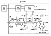
図1は、本発明を適用した搬送装置を備える印刷装置の実施の形態例に係る概略構成図である。図1に示すプリンター2が本実施の形態例に係る印刷装置であり、当該印刷装置は、ロール状に保持された用紙26を給紙ローラー29(上流側ローラー)及び搬送ローラー30(下流側ローラー)で印刷位置に搬送して印刷処理を実行するが、ジョブ間などに行われる逆搬送時において、すなわち、ロール回転部36の駆動により用紙26をロール紙25として所定位置まで巻き取る際に、給紙ローラー29とロール回転部36(ロール紙25)との間において用紙26に弛み(第1の弛み)を持たせた状態で、給紙ローラー29及びロール回転部36の駆動により用紙26を逆搬送し、その後、ロール回転部36の駆動が停止する前に、搬送ローラー30とその従動ローラー28Bで用紙26を押さえた状態で、給紙ローラー29を正方向に駆動することにより用紙26を所定距離だけ搬送する。これにより、巻取り中にロール紙25側で用紙26のずれが発生した場合にも上記弛みによりそのずれが下流側に伝播しづらくなり、また、上記正方向への搬送により給紙ローラー29と搬送ローラー30の間にも弛み(第2の弛み)が生成されるため、ロール回転部36が用紙26の巻取りを終了する時点でその制御時間や惰性により用紙26を巻き取り過ぎてしまう分をこの弛みで吸収することができる。従って、停止位置を正確に保つことができ、下流側の用紙26のずれも小さく抑えることができるので正確な逆搬送が可能である。 FIG. 1 is a schematic configuration diagram according to an embodiment of a printing apparatus including a transport device to which the present invention is applied. The printer 2 shown in FIG. 1 is a printing apparatus according to the present embodiment, and the printing apparatus uses a paper 26 held in a roll shape as a paper feed roller 29 (upstream roller) and a conveyance roller 30 (downstream roller). ) To the printing position to execute the printing process. In reverse conveyance performed between jobs, for example, when the paper 26 is rolled up to a predetermined position as the roll paper 25 by driving the roll rotation unit 36, The sheet 26 is driven by driving the sheet feed roller 29 and the roll rotation unit 36 in a state where the sheet 26 is slackened (first slack) between the sheet feed roller 29 and the roll rotation unit 36 (roll sheet 25). Reverse feed, and then the paper feed roller 29 is square in a state where the paper 26 is pressed by the transport roller 30 and its driven roller 28B before the drive of the roll rotation unit 36 stops. Conveying the paper 26 by a predetermined distance by driving the. Thus, the shift by the loosening even when the displacement of the paper 26 in the paper roll 25 side occurs during winding becomes pleasure propagates downstream Dzu, also feed roller 29 by transport to the positive direction Since the slack (second slack) is also generated between the roller 30 and the conveying roller 30, when the roll rotating unit 36 finishes winding the paper 26, the paper 26 is taken up excessively due to the control time and inertia. Minutes can be absorbed by this slack. Therefore, the stop position can be accurately maintained, and the deviation of the downstream paper 26 can be suppressed to be small, so that accurate reverse conveyance is possible.
本プリンター2は、図1に示すように、コンピューターなどのホスト装置1からの指示を受けて印刷処理を実行する装置であり、ここでは、一例として、ロール紙25を用紙26として使用し、用紙26を搬送しながら連続的に印刷を実行する印刷装置である。 As shown in FIG. 1, the printer 2 is a device that executes a printing process in response to an instruction from a host device 1 such as a computer. Here, as an example, the printer 2 uses a roll paper 25 as a paper 26. 26 is a printing apparatus that continuously performs printing while transporting 26.
図1ではプリンター2の概略構成を模式的に示しているが、プリンター2は、印刷内容を制御し用紙26に印刷処理を実行する印刷系と用紙26の搬送を担う搬送系が備えられる。 In FIG. 1, the schematic configuration of the printer 2 is schematically illustrated. However, the printer 2 includes a printing system that controls printing contents and executes a printing process on the paper 26 and a transport system that transports the paper 26.
印刷系には、印刷制御部21が設けられ、当該印刷制御部21は、ホスト装置1からの印刷指示を受信し、当該指示に従ってヘッド部23に印刷命令を出すと共に搬送系の搬送制御部22に対して用紙26の搬送要求を出す。ヘッド部23では、当該印刷命令に従ってヘッド部23とプラテン24との間を所定速度で移動する用紙26に対して印刷処理を実行する。
The printing system is provided with a printing control unit 21, which receives a printing instruction from the host device 1, issues a printing command to the
搬送系では、図1に示されるように、印刷媒体の格納(保持)場所にロール紙25として保持される用紙26を、搬送路33に沿って正方向(下流方向)に連続搬送し、印刷済みの部分をカッター34で切断して排紙ローラー32を介してプリンター2から排出する動作を実行する。また、当該搬送動作の後などに、用紙26の先端がヘッド部23よりも上流側の所定位置(頭出し位置)に来るように逆方向(上流方向)への逆搬送動作も実行する。
In the transport system, as shown in FIG. 1, the paper 26 held as the roll paper 25 is continuously transported in the forward direction (downstream direction) along the transport path 33 in the storage (holding) place of the print medium, and printing is performed. An operation of cutting the completed portion with the
当該搬送系には、それぞれ対応するモーター(27A及び27B)で駆動される給紙ローラー29(上流側ローラー)及び搬送ローラー30(下流側ローラー)が備えられる。当該両ローラーには、それぞれ、用紙26を挟んで対向する位置に従動ローラー(28A及び28B)が配置される。各従動ローラーは、用紙26の面に垂直方向に移動可能であり、上下二つの位置を取ることができる。用紙26と接する下の位置では、用紙26の面に垂直下向きの力が付勢され、各ローラー(29、30)と共に用紙26を挟んで、用紙26の面と垂直な方向の力で用紙26を押さえている。この状態を、ここではニップ状態と呼ぶこととする。また、用紙26から離間した上の位置では、この用紙26を押さえる力は作用せず、この状態をレリース状態と呼ぶこととする。 The transport system includes a paper feed roller 29 (upstream roller) and a transport roller 30 (downstream roller) driven by corresponding motors (27A and 27B). On both the rollers, driven rollers (28A and 28B) are arranged at positions facing each other with the paper 26 interposed therebetween. Each driven roller is movable in the direction perpendicular to the surface of the paper 26 and can take two positions, upper and lower. At a lower position in contact with the paper 26, a vertical downward force is applied to the surface of the paper 26, and the paper 26 is sandwiched by the rollers (29, 30) and the force of the paper 26 is perpendicular to the surface of the paper 26. Is holding down. This state is referred to herein as a nip state. Further, at the upper position away from the paper 26, the force pressing the paper 26 does not act, and this state is referred to as a release state.
給紙ローラー29は、ロール紙25として保持される用紙26を搬送路33に供給する機能を有し、減速機を介して伝えられるモーター27Aのトルクによって回転し、従動ローラー28Aと共に押圧する用紙26との間の摩擦力によって用紙26を移動させる。また、当該ローラーは用紙26を逆搬送する際にも用いられる。 The paper feed roller 29 has a function of supplying the paper 26 held as the roll paper 25 to the transport path 33, rotates by the torque of the motor 27A transmitted through the speed reducer, and presses the paper 26 together with the driven roller 28A. The paper 26 is moved by the frictional force between the two. The roller is also used when the paper 26 is reversely conveyed.
搬送ローラー30は、給紙ローラー29によって供給された用紙26を印刷位置へ、すなわち、ヘッド部23の位置へ搬送する機能を有し、減速機を介して伝えられるモーター27Bのトルクによって回転し、従動ローラー28Bと共に押圧する用紙26との間の摩擦力によって用紙26を移動させる。
The transport roller 30 has a function of transporting the paper 26 supplied by the paper feed roller 29 to the printing position, that is, to the position of the
また、給紙ローラー29及び搬送ローラー30には、それぞれ、エンコーダー31A及び31Bが設けられ、それらによって検知される両ローラーの回転が搬送制御部22へ通知される。更に、給紙ローラー29の従動ローラー28Aにも、エンコーダー31Dが設けられ、これにより、同様に従動ローラー28Aの回転が検知されて搬送制御部22へ通知される。当該エンコーダー31Dは逆搬送時に用いられる。
The paper feed roller 29 and the transport roller 30 are provided with
また、給紙ローラー29と搬送ローラー30の間には、用紙ガイド35が設けられる。図2は、用紙ガイド35の概略斜視図である。図2に示されるように、用紙ガイド35は、用紙26の巾方向両側に配置される板状の部材で構成され、用紙26と所定のギャップをもって用紙を挟むように設けられる。これにより、用紙26の巾方向の位置が規定され、用紙26が巾方向に所定量以上ずれないようにされる。 A paper guide 35 is provided between the paper feed roller 29 and the transport roller 30. FIG. 2 is a schematic perspective view of the paper guide 35. As shown in FIG. 2, the paper guide 35 is configured by a plate-like member disposed on both sides of the paper 26 in the width direction, and is provided so as to sandwich the paper with a predetermined gap from the paper 26. As a result, the position in the width direction of the sheet 26 is defined, and the sheet 26 is prevented from shifting by a predetermined amount or more in the width direction.
次に、搬送系には、ロール回転部36が備えられる。ロール回転部36は、ロール紙25として保持される用紙26を回転させ、送り出した用紙26を巻き取る動作を実行する。当該ロール回転部36は、モーター27Cによって駆動され、モーター27Cのトルクを伝達する減速機(駆動輪列)、減速機を介して伝えられる前記トルクによって回転する、ロール紙25の芯内を貫通する軸棒などで構成される。 Next, a roll rotation unit 36 is provided in the transport system. The roll rotation unit 36 rotates the paper 26 held as the roll paper 25 and performs an operation of winding the fed paper 26. The roll rotating unit 36 is driven by a motor 27C, and passes through the core of the roll paper 25 rotated by the speed reducer (drive wheel train) that transmits the torque of the motor 27C and the torque transmitted through the speed reducer. Consists of shaft rods.
また、ロール回転部36にもエンコーダー31Cが設けられ、それらによって検知されるロール紙25の回転が搬送制御部22へ通知される。
The roll rotation unit 36 is also provided with an encoder 31 </ b> C, and the
次に、図1に示す搬送制御部22は、搬送系を制御する部分であり、印刷制御部21からの指示に基づいて用紙26の上記搬送動作を制御する。特に、給紙ローラー29、搬送ローラー30及びロール回転部36の駆動・停止を制御して正方向及び逆方向への用紙26の良好な搬送を実行させる。このうち逆方向の搬送制御に本プリンター2の特徴があり、その具体的内容については後述する。
Next, the
搬送制御部22は、図示していないが、CPU、ROM、RAM、NVRAM(不揮発性メモリ)等で構成されており、搬送制御部22が実行する上記処理は、主にROMに格納されるプログラムに従ってCPUが動作することによって実行される。
Although not shown, the
上記RAMには、処理に必要な各データが一時的に保持され、給紙ローラー29、搬送ローラー30及びロール回転部36等の駆動・停止制御に必要な上記各エンコーダー31の検出値等が記憶される。 Each data necessary for processing is temporarily stored in the RAM, and detection values of the encoders 31 necessary for driving / stopping control of the paper feed roller 29, the transport roller 30, the roll rotating unit 36, and the like are stored. Is done.
なお、給紙ローラー29、搬送ローラー30、ロール回転部36及び搬送制御部22を含む当該搬送系が本発明の搬送装置に相当する。
In addition, the said conveyance system containing the paper feed roller 29, the conveyance roller 30, the roll rotation part 36, and the
以上説明したような構成を有する本プリンター2では、用紙26の搬送制御に特徴があり、以下、その具体的な内容について説明する。 The printer 2 having the above-described configuration is characterized by the conveyance control of the paper 26, and the specific contents thereof will be described below.
前述のとおり、本プリンター2では、所定の速度で搬送される用紙26に対して印刷処理を実行するので、印刷処理時には、搬送系は、正方向への搬送動作を実行する。この時、搬送制御部22は、印刷処理が開始されると、給紙ローラー29及び搬送ローラー30の搬送速度が上記所定速度に素早くなるように制御し、印刷処理が終了するまでその搬送速度を維持し、印刷処理が終了すると両ローラーを停止させる。
As described above, since the printer 2 performs the printing process on the paper 26 that is conveyed at a predetermined speed, the conveyance system performs a conveying operation in the forward direction during the printing process. At this time, when the printing process is started, the
また、カッター34による用紙26の切断処理後や印刷系のメンテナンス(ヘッド部23に備えられるノズルのフラッシング等)の際に、用紙26の先端を所定の印刷待機位置(頭出し位置)まで戻す動作が必要であり、このような場合、搬送系は、逆方向への搬送動作(巻き取り動作)を実行する。以下、この逆搬送動作について具体的に説明する。
In addition, after the cutting process of the paper 26 by the
図3は、搬送制御部22が逆搬送動作時に実行する処理の手順を例示したフローチャートである。まず、搬送制御部22は、印刷制御部21から用紙の逆搬送開始指示を受信すると(ステップS1)、搬送ローラー30の従動ローラー28Bを前述した上の位置にし、すなわち、レリースし、用紙26対する押圧力を解放する(ステップS2)。
FIG. 3 is a flowchart illustrating a procedure of processing executed by the
図4は、逆搬送動作時の各ステップにおける状態を説明するための図である。図4の(A)は、搬送ローラー30のレリース後の状態を示している。この状態は、例えば、正方向への搬送直後であり、用紙26は弛みなく搬送路上にあり、その先端は、ヘッド部23(印刷位置)よりも下流側に位置する。 FIG. 4 is a diagram for explaining a state in each step during the reverse conveyance operation. FIG. 4A shows a state after the release of the transport roller 30. This state is, for example, immediately after the conveyance in the forward direction, the paper 26 is on the conveyance path without slack, and the leading end thereof is located downstream of the head portion 23 (printing position).
次に、搬送制御部22は、逆搬送をする際の給紙ローラー29及びロール回転部36の速度と搬送量を決定する(ステップS3)。搬送量は、当該動作前の用紙26の先端位置に基づいて決定される。前述した切断後の動作の場合には、カッター34から上記印刷待機位置までの距離が搬送量となる。また、給紙ローラー29による搬送速度は逆搬送について予め定められた値(Vk)とし、ロール回転部36による搬送速度は、その時点におけるロール紙25の直径の値等から、給紙ローラー29による搬送速度以下の速度(Vr≦Vk)が決定される。
Next, the
その後、搬送制御部22は、給紙ローラー29の駆動を開始する(ステップS4)。ロール回転部36の駆動については、この時に同時に開始してもよいし、所定の時間が経過した後に開始してもよい。前者の場合には、ロール回転部36による搬送速度(Vr)が給紙ローラー29による搬送速度(Vk)よりもかなり小さな値として決定されている必要があり、この開始タイミングは上記速度との兼合いで適宜設定されされ得るが、逆搬送中に給紙ローラー29とロール紙25の間で用紙26の弛みができるように、また、その弛み量が所定の範囲内に入るように設定される。
Thereafter, the
このようにして、給紙ローラー29及びロール回転部36の駆動が開始されると、それ以降、搬送制御部22は、上記決定した各搬送速度になるように、前述したエンコーダー31A、31Cの検出値に基づいてPID制御を行う。
In this way, when driving of the paper feed roller 29 and the roll rotating unit 36 is started, the
図4の(B)は、この逆搬送中の状態を示している。上述のとおり、給紙ローラー29とロール回転部36では搬送速度、駆動開始タイミングで差があるため、給紙ローラー29の搬送が先行し、図に示すように、給紙ローラー29とロール紙25の間で用紙26の弛みが発生する。また、用紙26の先端位置は上記印刷待機位置へ近づいている。 FIG. 4B shows a state during reverse conveyance. As described above, since there is a difference in the conveyance speed and the drive start timing between the paper feed roller 29 and the roll rotating unit 36, the conveyance of the paper feed roller 29 precedes and as shown in the drawing, the paper feed roller 29 and the roll paper 25 The slack of the paper 26 occurs between the two. Further, the leading end position of the paper 26 is approaching the print standby position.
その後、逆方向への搬送が進み、給紙ローラー29による搬送量が上記決定した搬送量に達した時点で、搬送制御部22は、給紙ローラー29を停止する(ステップS5)。そして直ちに、搬送制御部22は、搬送ローラー30をニップする(ステップS6)。すなわち、従動ローラー28Bを下の位置に移動させ、用紙26を押圧するニップ状態とする。
Thereafter, the conveyance in the reverse direction proceeds, and when the conveyance amount by the paper feed roller 29 reaches the determined conveyance amount, the
図4の(C)は、当該ニップ後の状態を示している。この時点で給紙ローラー29による逆搬送は完了しているので、用紙26の先端は上記印刷待機位置に達しており、給紙ローラー29は停止している。また、ロール回転部36による搬送(巻き取り)は、上述のとおり、給紙ローラー29よりも遅れているので、この時点ではロール回転部36は駆動を続けており、上述した弛みは、給紙ローラー29が停止した時点で最大となっている。 FIG. 4C shows a state after the nip. At this point, since the reverse conveyance by the paper feed roller 29 is completed, the leading edge of the paper 26 has reached the print standby position, and the paper feed roller 29 is stopped. Further, since the conveyance (winding) by the roll rotation unit 36 is delayed as compared with the paper feed roller 29 as described above, the roll rotation unit 36 continues to be driven at this time, and the above-described slack is caused by the paper feed. It is the maximum when the roller 29 stops.
上記ニップが終了すると直ちに、搬送制御部22は、給紙ローラー29を正方向に駆動し、用紙26を正方向に予め定められた距離だけ搬送する(ステップS7)。図4の(D)は、その状態を示している。ここでは、上述のとおり、搬送ローラー30がニップされた状態で、すなわち、用紙26が押さえられた状態で、給紙ローラー29から正方向に用紙26が搬送されるため、用紙26の先端は動かず、給紙ローラー29と搬送ローラー30の間で用紙26に弛みができる状態になる。なお、この正方向への搬送中には、ロール回転部36による上記巻き取りは未だ完了しないが、給紙ローラー29とロール紙25の間の弛みは減少し続けている。
Immediately after the nip is completed, the
上記所定量の正方向の搬送が完了すると、搬送制御部22は、給紙ローラー29を停止する。
When the predetermined amount of forward conveyance is completed, the
その後、搬送制御部22は、給紙ローラー29の従動ローラー28Aに設けられるエンコーダー31Dが回転を検出するのを監視する。上記ステップS7の終了時点で、給紙ローラー29及び搬送ローラー30の駆動は停止しており、給紙ローラー29部分での用紙26の移動はなくなっているので、この時点でのエンコーダー31Dによる回転の検出は、用紙26がロール回転部36の巻き取り駆動によって引っ張られて上流側へ移動したことを意味している。すなわち、給紙ローラー29とロール紙25の間の弛みなくなったことを意味している。
Thereafter, the
搬送制御部22は、この用紙26の移動を確認すると(ステップS8)、ロール回転部36による巻き取りが完了しているので、直ちに、ロール回転部36の駆動を停止する(ステップS9)。具体的には、モーター27Cのデューティ値(Duty値、電流供給値)を直ちにゼロにする。より具体的には、例えば、上記エンコーダー31Dによる回転の検出後、1エンコーダーパルス(EP)後にデューティ値をゼロにする。なお、上記エンコーダー31Dによる回転の検出は、確実にロール紙25側から用紙26が引っ張られて移動したことを検出するため、所定の複数回、回転が検出されたことを持って回転の検出とすることが好ましい。
When the
図5は、上記ロール回転部36の駆動停止を説明するための図である。図5は、ロール回転部36による搬送速度(V)を経時的(T)に例示したグラフであり、時刻Tsで上記エンコーダー31Dによる回転の検出がなされた場合を示している。曲線Aは従来一般的に行われている速度曲線であり、この場合には、この曲線に示される刻々の速度になるように上述したPID制御が適宜なされて、最終的に速度がゼロとなる。
FIG. 5 is a diagram for explaining the drive stop of the roll rotating unit 36. FIG. 5 is a graph illustrating the transport speed (V) by the roll rotating unit 36 over time (T), and shows a case where the rotation is detected by the
一方、曲線Bは、上述した直ちにモーター27Cのデューティ値をゼロにする場合であり、明らかに、こちらの方が短時間かつ短移動距離でロール回転部36の回転を停止することができる。また、上記従来の制御では、ロール紙25のイナーシャ等の環境変動により実際の速度が曲線Aから上下に振れることがあり、その場合には更に時間及び搬送距離が長くなってしまう。 On the other hand, a curve B is a case where the duty value of the motor 27C is immediately set to zero as described above, and obviously, this can stop the rotation of the roll rotating unit 36 in a short time and with a short moving distance. In the conventional control, the actual speed may fluctuate up and down from the curve A due to environmental fluctuations such as inertia of the roll paper 25. In this case, the time and the transport distance are further increased.
図4の(E)は、ロール回転部36が停止した時点の状態、すなわち、当該逆搬送動作が終了した時点の状態を示している。ここでは、前述のとおり、ロール回転部36による巻き取りが終了しているので、給紙ローラー29とロール紙25間の弛みはなくなり、正方向への搬送が可能な状態となっている。また、上述の通り、この弛みがなくなって以降ロール回転部36が実際に停止するまでに、制御時間及びロール紙25のイナーシャによって用紙26が上流側へ移動するが、その移動は、上記発生させた給紙ローラー29と搬送ローラー30間の弛みによって吸収される。従って、当該弛み量が減少する。しかし、当該弛みがなくならないように弛みを発生させているので、用紙26の先端が引っ張られることはなく、その位置は印刷待機位置に維持される。 FIG. 4E shows a state at the time when the roll rotating unit 36 stops, that is, a state at the time when the reverse conveying operation is finished. Here, as described above, since the winding by the roll rotation unit 36 has been completed, the slack between the paper feed roller 29 and the roll paper 25 is eliminated, and the conveyance in the forward direction is possible. Further, as described above, the sheet 26 moves upstream due to the control time and the inertia of the roll paper 25 until the roll rotation unit 36 actually stops after the loosening is eliminated. It is absorbed by the slack between the paper feed roller 29 and the transport roller 30. Accordingly, the amount of looseness is reduced. However, since the slack is generated so that the slack does not disappear, the leading edge of the paper 26 is not pulled, and the position is maintained at the print standby position.
このようにして、当該指示を受けた逆搬送動作は終了するが、搬送制御部22は、ステップS7終了時点以降の用紙26の逆方向への搬送量を上記RAM又は上記NVRAMに記憶する(ステップS10)。すなわち、ステップS7で生成した給紙ローラー29と搬送ローラー30間の弛みがどれだけ減少しているかを、言い換えれば、給紙ローラー29と搬送ローラー30間にどれだけの弛みがあるかを記憶しておく。この値は、次回の正方向への搬送処理に用いられる。例えば、次回の搬送時において給紙ローラー29と搬送ローラー30間に必要な弛み量が不足する場合には、その不足分を補うように給紙ローラー29と搬送ローラー30の起動タイミングがずらされる。
In this way, the reverse transport operation in response to the instruction ends, but the
以上のようにして一連の逆搬送制御が終了する。 A series of reverse conveyance control is completed as described above.
以上説明したように、本実施の形態例に係るプリンター2の搬送系では、用紙26をロール紙25側へ巻き取る逆搬送動作において、給紙ローラー29とロール紙25間に弛みを発生させた状態で用紙26を巻き取るため、ロール紙25側で用紙26の巾方向の位置や方向にずれが生じた場合にも、そのずれが上流側に伝播しずらく、給紙ローラー29から下流側の用紙26を大きくずらしてしまう虞がない。従って、用紙ガイド35等の搬送路33の構造物に強く接してジャム状態となってしまうことを避けることができると共に、ずれの少ない良好な状態で用紙26を印刷位置に供給できるので印刷品質を向上させることができる。 As described above, in the transport system of the printer 2 according to the present embodiment, slack is generated between the paper feed roller 29 and the roll paper 25 in the reverse transport operation of winding the paper 26 to the roll paper 25 side. Since the paper 26 is wound in the state, even if a deviation occurs in the width direction position or direction of the paper 26 on the roll paper 25 side, the deviation hardly propagates to the upstream side. There is no possibility that the paper 26 will be greatly displaced. Accordingly, it is possible to avoid jamming due to strong contact with the structure of the conveyance path 33 such as the paper guide 35, and the paper 26 can be supplied to the printing position in a good state with little deviation. Can be improved.
また、給紙ローラー29による逆搬送の後に、給紙ローラー29と搬送ローラー30間に用紙26の弛みを発生させておくので、ロール回転部36の停止すべきタイミングから実際に停止するまでに移動してしまう距離を、この弛みで吸収することができ、用紙26の先端を正しい位置に保持することができ、短時間で正確な逆搬送を行なうことができる。 Further, since the slack of the paper 26 is generated between the paper feed roller 29 and the transport roller 30 after the reverse conveyance by the paper feed roller 29, the roll rotation unit 36 moves from the timing to stop until it actually stops. Thus, the slackness can be absorbed by the slack, the leading edge of the paper 26 can be held at the correct position, and accurate reverse conveyance can be performed in a short time.
また、上述の通り、ロール回転部36を即座に停止できるようにしたので、上記実際に停止するまでに移動してしまう距離を短くでき、それにより、上記発生させておく給紙ローラー29と搬送ローラー30間の弛みを小さく設定できる。これにより、弛みによって搬送路33の構造体を大型化する必要がなく、また、逆搬送動作の所要時間を短く抑えることができるのでプリンター2のスループットの向上を図ることができる。 Further, as described above, since the roll rotating unit 36 can be stopped immediately, the distance that the roll rotating unit 36 moves until it is actually stopped can be shortened. The slack between the rollers 30 can be set small. Thereby, it is not necessary to increase the size of the structure of the transport path 33 due to the slack, and the time required for the reverse transport operation can be kept short, so that the throughput of the printer 2 can be improved.
また、用紙ガイド35により、用紙26の巾方向の位置を規定できるので、更に、正確な搬送が可能になる。 Further, since the position in the width direction of the paper 26 can be defined by the paper guide 35, further accurate conveyance is possible.
また、ロール回転部36の停止タイミングをエンコーダーによる比較的容易な構成で検知することができる。 Further, the stop timing of the roll rotating unit 36 can be detected with a relatively easy configuration using an encoder.
なお、本実施の形態例では、印刷媒体が紙であったがシート状の媒体であればこれに限定されることはない。 In this embodiment, the print medium is paper, but the present invention is not limited to this as long as it is a sheet-like medium.
また、本実施の形態例では、搬送装置がプリンターに設けられたが、本発明を適用した搬送装置は、シート状物に機械加工、レーザー加工、液体噴射加工などの各種処理を施す装置に設けて利用することができる。 In this embodiment, the transport device is provided in the printer. However, the transport device to which the present invention is applied is provided in a device that performs various processes such as machining, laser processing, and liquid jet processing on the sheet-like material. Can be used.
本発明の保護範囲は、上記の実施の形態に限定されず、特許請求の範囲に記載された発明とその均等物に及ぶものである。 The protection scope of the present invention is not limited to the above-described embodiment, but covers the invention described in the claims and equivalents thereof.
1 ホスト装置、 2 プリンター、 21 印刷制御部、 22 搬送制御部、 23 ヘッド部、 24 プラテン、 25 ロール紙、 26 用紙、 27A、B、C モーター、 28A、B 従動ローラー、 29 給紙ローラー、 30 搬送ローラー、 31A、B、C、D エンコーダー、 32 排紙ローラー、 33 搬送路、 34 カッター、 35 用紙ガイド、 36 ロール回転部 DESCRIPTION OF SYMBOLS 1 Host apparatus, 2 Printer, 21 Print control part, 22 Transport control part, 23 Head part, 24 Platen, 25 Roll paper, 26 Paper, 27A, B, C motor, 28A, B Drive roller, 29 Paper feed roller, 30 Conveyance roller, 31A, B, C, D Encoder, 32 Discharge roller, 33 Conveyance path, 34 Cutter, 35 Paper guide, 36 Roll rotating part
Claims (6)
前記制御部は、前記被処理媒体を巻き取る動作時に、前記上流側ローラーと前記ロール回転部の駆動により第1の弛みを発生させて前記被処理媒体を搬送方向の上流側へ搬送し、当該ロール回転部の駆動を停止させる前に、前記上流側ローラーの駆動により、第2の弛みを発生させ、
前記第1の弛みは、前記上流側ローラーと前記ロール状に保持された被処理媒体との間に発生し、
前記制御部は、前記下流側ローラーが前記被処理媒体を押圧しない状態で前記上流側ローラーと前記ロール回転部を駆動させることにより、前記第1の弛みを発生させた状態で、前記被処理媒体の先端を所定位置まで移動させ、
前記第2の弛みは、前記上流側ローラーと前記下流側ローラーとの間に発生し、
前記制御部は、前記下流側ローラーが前記被処理媒体を押圧する状態で前記上流側ローラーの前記搬送方向への駆動により、前記第2の弛みを発生させた状態で、前記被処理媒体を搬送方向の下流側へ所定量搬送させる
ことを特徴とする搬送装置。 An upstream roller that feeds a sheet-like processed medium held in a roll shape to a conveyance path, a downstream roller that supplies the fed processed medium to a processing position, and the processed medium held in the roll shape A roll rotating unit that winds the sent processing medium, and a controller that controls the driving of the upstream roller, the downstream roller, and the roll rotating unit to convey the processing medium A conveying device having
The control unit generates a first slack by driving the upstream roller and the roll rotation unit during the operation of winding the processing medium, and transports the processing medium to the upstream side in the transport direction. Before stopping the driving of the roll rotation unit, the second slack is generated by driving the upstream roller ,
The first slack is generated between the upstream roller and the processing medium held in the roll shape,
The control unit is configured to drive the upstream roller and the roll rotation unit in a state where the downstream roller does not press the processing target medium, thereby generating the first slack, and Move the tip of the
The second slack occurs between the upstream roller and the downstream roller,
The controller transports the processing medium in a state where the second slack is generated by driving the upstream roller in the transporting direction while the downstream roller presses the processing medium. A transport device that transports a predetermined amount downstream in the direction .
前記被処理媒体の巻き取り動作時における前記ロール回転部の駆動タイミングは前記上流側ローラーの駆動タイミングよりも遅い、あるいは、前記被処理媒体の巻き取り動作時における前記ロール回転部による搬送速度は前記上流側ローラーによる搬送速度よりも遅いことを特徴とする搬送装置。 In claim 1,
The drive timing of the roll rotation unit during the winding operation of the processing medium is slower than the driving timing of the upstream roller, or the conveyance speed by the roll rotation unit during the winding operation of the processing medium is A transport apparatus characterized by being slower than a transport speed by an upstream roller.
前記上流側ローラー及び前記ロール回転部の駆動制御は、前記上流側ローラー及び前記ロール回転部にそれぞれ設けられるエンコーダーの検出値に基づいて行われる
ことを特徴とする搬送装置。 In claim 1 or 2 ,
Drive control of the said upstream roller and the said roll rotation part is performed based on the detected value of the encoder respectively provided in the said upstream roller and the said roll rotation part. The conveying apparatus characterized by the above-mentioned.
前記制御部は、前記被処理媒体を巻き取る動作時に、前記上流側ローラーと前記ロール回転部の駆動により第1の弛みを発生させて前記被処理媒体を搬送方向の上流側へ搬送し、当該ロール回転部の駆動を停止させる前に、前記上流側ローラーの駆動により、第2の弛みを発生させ、
前記第1の弛みは、前記上流側ローラーと前記ロール状に保持された被処理媒体との間に発生し、
前記制御部は、前記下流側ローラーが前記被処理媒体を押圧しない状態で前記上流側ローラーと前記ロール回転部を駆動させることにより、前記第1の弛みを発生させた状態で、前記被処理媒体の先端を所定位置まで移動させ、
前記第2の弛みは、前記上流側ローラーと前記下流側ローラーとの間に発生し、
前記制御部は、前記下流側ローラーが前記被処理媒体を押圧する状態で前記上流側ローラーの前記搬送方向への駆動により、前記第2の弛みを発生させた状態で、前記被処理媒体を搬送方向の下流側へ所定量搬送させる
ことを特徴とする搬送方法。 An upstream roller that feeds a sheet-like processed medium held in a roll shape to a conveyance path, a downstream roller that supplies the fed processed medium to a processing position, and the processed medium held in the roll shape A roll rotating unit that winds the sent processing medium, and a controller that controls the driving of the upstream roller, the downstream roller, and the roll rotating unit to convey the processing medium And a transport method in a transport device having:
The control unit generates a first slack by driving the upstream roller and the roll rotation unit during the operation of winding the processing medium, and transports the processing medium to the upstream side in the transport direction. Before stopping the driving of the roll rotation unit, the second slack is generated by driving the upstream roller ,
The first slack is generated between the upstream roller and the processing medium held in the roll shape,
The control unit is configured to drive the upstream roller and the roll rotation unit in a state where the downstream roller does not press the processing target medium, thereby generating the first slack, and Move the tip of the
The second slack occurs between the upstream roller and the downstream roller,
The controller transports the processing medium in a state where the second slack is generated by driving the upstream roller in the transporting direction while the downstream roller presses the processing medium. Transporting a predetermined amount downstream in the direction .
前記被処理媒体の巻き取り動作時における前記ロール回転部の駆動タイミングは前記上流側ローラーの駆動タイミングよりも遅い、あるいは、前記被処理媒体の巻き取り動作時における前記ロール回転部による搬送速度は前記上流側ローラーによる搬送速度よりも遅いことを特徴とする搬送方法。
In claim 5 ,
The drive timing of the roll rotation unit during the winding operation of the processing medium is slower than the driving timing of the upstream roller, or the conveyance speed by the roll rotation unit during the winding operation of the processing medium is A transport method characterized by being slower than the transport speed by the upstream roller.
Priority Applications (4)
| Application Number | Priority Date | Filing Date | Title |
|---|---|---|---|
| JP2011152870A JP5776386B2 (en) | 2011-07-11 | 2011-07-11 | Conveying apparatus, printing apparatus, and conveying method |
| US13/541,986 US8657436B2 (en) | 2011-07-11 | 2012-07-05 | Media conveyance device, printing device, and media conveyance method |
| CN201210232579.5A CN102874619B (en) | 2011-07-11 | 2012-07-05 | Media conveyance device, printing device, and media conveyance method |
| TW101124504A TWI477431B (en) | 2011-07-11 | 2012-07-06 | Media conveyance device, printing device, and media conveyance method |
Applications Claiming Priority (1)
| Application Number | Priority Date | Filing Date | Title |
|---|---|---|---|
| JP2011152870A JP5776386B2 (en) | 2011-07-11 | 2011-07-11 | Conveying apparatus, printing apparatus, and conveying method |
Publications (3)
| Publication Number | Publication Date |
|---|---|
| JP2013018602A JP2013018602A (en) | 2013-01-31 |
| JP2013018602A5 JP2013018602A5 (en) | 2014-08-21 |
| JP5776386B2 true JP5776386B2 (en) | 2015-09-09 |
Family
ID=47690440
Family Applications (1)
| Application Number | Title | Priority Date | Filing Date |
|---|---|---|---|
| JP2011152870A Expired - Fee Related JP5776386B2 (en) | 2011-07-11 | 2011-07-11 | Conveying apparatus, printing apparatus, and conveying method |
Country Status (1)
| Country | Link |
|---|---|
| JP (1) | JP5776386B2 (en) |
Families Citing this family (3)
| Publication number | Priority date | Publication date | Assignee | Title |
|---|---|---|---|---|
| JP6064784B2 (en) * | 2013-05-24 | 2017-01-25 | セイコーエプソン株式会社 | Conveying apparatus, printing apparatus, and conveying method |
| JP6447262B2 (en) * | 2015-03-10 | 2019-01-09 | 沖電気工業株式会社 | Automatic transaction equipment |
| JP7278918B2 (en) * | 2019-09-30 | 2023-05-22 | 株式会社Screenホールディングス | TENSION ADJUSTMENT METHOD IN PRINTING DEVICE AND PRINTING DEVICE |
Family Cites Families (2)
| Publication number | Priority date | Publication date | Assignee | Title |
|---|---|---|---|---|
| JPH06144664A (en) * | 1992-11-09 | 1994-05-24 | Mimaki Eng:Kk | Method of correcting slippage of roll paper delivered to plotter, and plotter used therefor |
| JP5272580B2 (en) * | 2008-04-25 | 2013-08-28 | セイコーエプソン株式会社 | Printing apparatus and printing method |
-
2011
- 2011-07-11 JP JP2011152870A patent/JP5776386B2/en not_active Expired - Fee Related
Also Published As
| Publication number | Publication date |
|---|---|
| JP2013018602A (en) | 2013-01-31 |
Similar Documents
| Publication | Publication Date | Title |
|---|---|---|
| TWI477431B (en) | Media conveyance device, printing device, and media conveyance method | |
| JP4442640B2 (en) | Image forming apparatus | |
| KR102406787B1 (en) | Inkjet printer, printing method using the same, and automatic web threading method | |
| JP5776386B2 (en) | Conveying apparatus, printing apparatus, and conveying method | |
| TWI464102B (en) | Conveyance device, printing device, and conveyance method | |
| JP2006151693A (en) | Sheet handling device | |
| JP2015054500A (en) | Image formation device and transportation control method of roll-like print medium | |
| JP7147422B2 (en) | MEDIA CONVEYING DEVICE, RECORDING DEVICE, AND RECORDING METHOD | |
| JP6381323B2 (en) | Recording device | |
| JP2011073841A (en) | Image forming device | |
| US9975721B2 (en) | Conveyance device, printer, and conveyance method | |
| JP5776388B2 (en) | Conveying apparatus, printing apparatus, and conveying method | |
| JP7031134B2 (en) | Printing device and control method of printing device | |
| JP2013018602A5 (en) | ||
| JP4822984B2 (en) | RECORDING MEDIUM CONVEYING DEVICE, CONVEYING METHOD, AND RECORDING DEVICE | |
| JP5899972B2 (en) | Printing apparatus and conveying method of printing apparatus | |
| JP5854684B2 (en) | Recording device | |
| JP5245652B2 (en) | Printing apparatus and printing medium conveyance control method in printing apparatus | |
| JP4818829B2 (en) | Printing apparatus, conveying apparatus, and printing method | |
| JP6997503B2 (en) | Printing unit | |
| JP5834614B2 (en) | Conveying apparatus, printing apparatus, and conveying method | |
| JP5790154B2 (en) | Conveying apparatus, printing apparatus, and conveying method | |
| JP5791417B2 (en) | Recording device | |
| JP2015037839A (en) | Printer and control method for printer | |
| JP2013170024A (en) | Conveyance device, printer and conveyance method |
Legal Events
| Date | Code | Title | Description |
|---|---|---|---|
| A521 | Request for written amendment filed |
Free format text: JAPANESE INTERMEDIATE CODE: A523 Effective date: 20140709 |
|
| A621 | Written request for application examination |
Free format text: JAPANESE INTERMEDIATE CODE: A621 Effective date: 20140709 |
|
| A977 | Report on retrieval |
Free format text: JAPANESE INTERMEDIATE CODE: A971007 Effective date: 20150319 |
|
| A131 | Notification of reasons for refusal |
Free format text: JAPANESE INTERMEDIATE CODE: A131 Effective date: 20150324 |
|
| A521 | Request for written amendment filed |
Free format text: JAPANESE INTERMEDIATE CODE: A523 Effective date: 20150522 |
|
| TRDD | Decision of grant or rejection written | ||
| A01 | Written decision to grant a patent or to grant a registration (utility model) |
Free format text: JAPANESE INTERMEDIATE CODE: A01 Effective date: 20150609 |
|
| A61 | First payment of annual fees (during grant procedure) |
Free format text: JAPANESE INTERMEDIATE CODE: A61 Effective date: 20150622 |
|
| R150 | Certificate of patent or registration of utility model |
Ref document number: 5776386 Country of ref document: JP Free format text: JAPANESE INTERMEDIATE CODE: R150 |
|
| S531 | Written request for registration of change of domicile |
Free format text: JAPANESE INTERMEDIATE CODE: R313531 |
|
| R350 | Written notification of registration of transfer |
Free format text: JAPANESE INTERMEDIATE CODE: R350 |
|
| LAPS | Cancellation because of no payment of annual fees |