JP4822984B2 - RECORDING MEDIUM CONVEYING DEVICE, CONVEYING METHOD, AND RECORDING DEVICE - Google Patents
RECORDING MEDIUM CONVEYING DEVICE, CONVEYING METHOD, AND RECORDING DEVICE Download PDFInfo
- Publication number
- JP4822984B2 JP4822984B2 JP2006227180A JP2006227180A JP4822984B2 JP 4822984 B2 JP4822984 B2 JP 4822984B2 JP 2006227180 A JP2006227180 A JP 2006227180A JP 2006227180 A JP2006227180 A JP 2006227180A JP 4822984 B2 JP4822984 B2 JP 4822984B2
- Authority
- JP
- Japan
- Prior art keywords
- roller
- recording medium
- motor
- drive motor
- conveyance
- Prior art date
- Legal status (The legal status is an assumption and is not a legal conclusion. Google has not performed a legal analysis and makes no representation as to the accuracy of the status listed.)
- Expired - Fee Related
Links
Images


Classifications
-
- B—PERFORMING OPERATIONS; TRANSPORTING
- B65—CONVEYING; PACKING; STORING; HANDLING THIN OR FILAMENTARY MATERIAL
- B65H—HANDLING THIN OR FILAMENTARY MATERIAL, e.g. SHEETS, WEBS, CABLES
- B65H7/00—Controlling article feeding, separating, pile-advancing, or associated apparatus, to take account of incorrect feeding, absence of articles, or presence of faulty articles
- B65H7/18—Modifying or stopping actuation of separators
-
- B—PERFORMING OPERATIONS; TRANSPORTING
- B65—CONVEYING; PACKING; STORING; HANDLING THIN OR FILAMENTARY MATERIAL
- B65H—HANDLING THIN OR FILAMENTARY MATERIAL, e.g. SHEETS, WEBS, CABLES
- B65H5/00—Feeding articles separated from piles; Feeding articles to machines
- B65H5/06—Feeding articles separated from piles; Feeding articles to machines by rollers or balls, e.g. between rollers
-
- B—PERFORMING OPERATIONS; TRANSPORTING
- B65—CONVEYING; PACKING; STORING; HANDLING THIN OR FILAMENTARY MATERIAL
- B65H—HANDLING THIN OR FILAMENTARY MATERIAL, e.g. SHEETS, WEBS, CABLES
- B65H2220/00—Function indicators
- B65H2220/09—Function indicators indicating that several of an entity are present
-
- B—PERFORMING OPERATIONS; TRANSPORTING
- B65—CONVEYING; PACKING; STORING; HANDLING THIN OR FILAMENTARY MATERIAL
- B65H—HANDLING THIN OR FILAMENTARY MATERIAL, e.g. SHEETS, WEBS, CABLES
- B65H2404/00—Parts for transporting or guiding the handled material
- B65H2404/10—Rollers
- B65H2404/14—Roller pairs
-
- B—PERFORMING OPERATIONS; TRANSPORTING
- B65—CONVEYING; PACKING; STORING; HANDLING THIN OR FILAMENTARY MATERIAL
- B65H—HANDLING THIN OR FILAMENTARY MATERIAL, e.g. SHEETS, WEBS, CABLES
- B65H2511/00—Dimensions; Position; Numbers; Identification; Occurrences
- B65H2511/20—Location in space
- B65H2511/21—Angle
- B65H2511/212—Rotary position
-
- B—PERFORMING OPERATIONS; TRANSPORTING
- B65—CONVEYING; PACKING; STORING; HANDLING THIN OR FILAMENTARY MATERIAL
- B65H—HANDLING THIN OR FILAMENTARY MATERIAL, e.g. SHEETS, WEBS, CABLES
- B65H2511/00—Dimensions; Position; Numbers; Identification; Occurrences
- B65H2511/20—Location in space
- B65H2511/24—Irregularities, e.g. in orientation or skewness
-
- B—PERFORMING OPERATIONS; TRANSPORTING
- B65—CONVEYING; PACKING; STORING; HANDLING THIN OR FILAMENTARY MATERIAL
- B65H—HANDLING THIN OR FILAMENTARY MATERIAL, e.g. SHEETS, WEBS, CABLES
- B65H2513/00—Dynamic entities; Timing aspects
- B65H2513/10—Speed
- B65H2513/11—Speed angular
-
- B—PERFORMING OPERATIONS; TRANSPORTING
- B65—CONVEYING; PACKING; STORING; HANDLING THIN OR FILAMENTARY MATERIAL
- B65H—HANDLING THIN OR FILAMENTARY MATERIAL, e.g. SHEETS, WEBS, CABLES
- B65H2513/00—Dynamic entities; Timing aspects
- B65H2513/20—Acceleration or deceleration
-
- B—PERFORMING OPERATIONS; TRANSPORTING
- B65—CONVEYING; PACKING; STORING; HANDLING THIN OR FILAMENTARY MATERIAL
- B65H—HANDLING THIN OR FILAMENTARY MATERIAL, e.g. SHEETS, WEBS, CABLES
- B65H2513/00—Dynamic entities; Timing aspects
- B65H2513/20—Acceleration or deceleration
- B65H2513/23—Acceleration or deceleration angular
-
- B—PERFORMING OPERATIONS; TRANSPORTING
- B65—CONVEYING; PACKING; STORING; HANDLING THIN OR FILAMENTARY MATERIAL
- B65H—HANDLING THIN OR FILAMENTARY MATERIAL, e.g. SHEETS, WEBS, CABLES
- B65H2513/00—Dynamic entities; Timing aspects
- B65H2513/40—Movement
-
- B—PERFORMING OPERATIONS; TRANSPORTING
- B65—CONVEYING; PACKING; STORING; HANDLING THIN OR FILAMENTARY MATERIAL
- B65H—HANDLING THIN OR FILAMENTARY MATERIAL, e.g. SHEETS, WEBS, CABLES
- B65H2513/00—Dynamic entities; Timing aspects
- B65H2513/40—Movement
- B65H2513/41—Direction of movement
- B65H2513/412—Direction of rotation of motor powering the handling device
-
- B—PERFORMING OPERATIONS; TRANSPORTING
- B65—CONVEYING; PACKING; STORING; HANDLING THIN OR FILAMENTARY MATERIAL
- B65H—HANDLING THIN OR FILAMENTARY MATERIAL, e.g. SHEETS, WEBS, CABLES
- B65H2513/00—Dynamic entities; Timing aspects
- B65H2513/50—Timing
- B65H2513/512—Starting; Stopping
-
- B—PERFORMING OPERATIONS; TRANSPORTING
- B65—CONVEYING; PACKING; STORING; HANDLING THIN OR FILAMENTARY MATERIAL
- B65H—HANDLING THIN OR FILAMENTARY MATERIAL, e.g. SHEETS, WEBS, CABLES
- B65H2515/00—Physical entities not provided for in groups B65H2511/00 or B65H2513/00
- B65H2515/70—Electrical or magnetic properties, e.g. electric power or current
-
- B—PERFORMING OPERATIONS; TRANSPORTING
- B65—CONVEYING; PACKING; STORING; HANDLING THIN OR FILAMENTARY MATERIAL
- B65H—HANDLING THIN OR FILAMENTARY MATERIAL, e.g. SHEETS, WEBS, CABLES
- B65H2555/00—Actuating means
- B65H2555/20—Actuating means angular
- B65H2555/25—D.C. motors, e.g. shunt motors
Description
本発明は、独立的に駆動される2つのローラを用いて記録媒体を搬送するための記録媒体の搬送装置、搬送方法、および、その搬送装置を備えた記録装置に関するものである。本願発明は、特に剛性の高い記録媒体を扱う装置に用いて好適である。 The present invention relates to a recording medium transport apparatus, a transport method, and a recording apparatus including the transport apparatus, for transporting a recording medium using two independently driven rollers. The present invention is particularly suitable for an apparatus that handles a recording medium having high rigidity.
インクジェットプリンタに代表される記録装置においては、記録媒体としての用紙を積載部から1枚ずつ分離した後、給紙ローラによって、その用紙を搬送ローラに向かって搬送する給紙機構が備えられている。その搬送ローラは、画像を記録するための記録部に備えられている。一般に、このような給紙機構においては、給紙条件の調整や駆動機構の簡略化などの目的から、給紙ローラと搬送ローラは、それぞれ個別のモータ駆動系によって駆動制御される。 2. Description of the Related Art A recording apparatus typified by an ink jet printer includes a paper feed mechanism that separates sheets as recording media one by one from a stacking unit and then conveys the paper toward a conveyance roller by a paper feed roller. . The conveyance roller is provided in a recording unit for recording an image. In general, in such a paper feed mechanism, the paper feed roller and the transport roller are driven and controlled by individual motor drive systems for the purpose of adjusting paper feed conditions and simplifying the drive mechanism.
このような給紙機構は、給紙ローラと搬送ローラとの協働によって用紙を搬送する際に、用紙に掛かる負荷を考慮して、それらの駆動タイミングおよび停止タイミングを最適に設定する必要がある。 In such a paper feeding mechanism, when the paper is transported by the cooperation of the paper feeding roller and the transport roller, it is necessary to optimally set the driving timing and stop timing in consideration of the load applied to the paper. .
そのための構成として、例えば特許文献1には、給紙ローラと搬送ローラの駆動系のそれぞれにクラッチを備えて、それらのローラ毎の駆動系毎のクラッチと駆動モータを関連的に制御する構成が記載されている。また特許文献2には、給紙ローラと搬送ローラとの間に位置する用紙の張力を検出するための張力検出手段を備え、その張力検出手段によって検出された用紙の張力に応じて、給紙ローラと搬送ローラを関連的に駆動制御する構成が記載されている。 As a configuration for that purpose, for example, Patent Document 1 has a configuration in which a clutch is provided for each of the drive systems of the paper feed roller and the transport roller, and the clutch and the drive motor for each of the rollers are related to each other. Are listed. Japanese Patent Application Laid-Open No. H10-228561 includes a tension detection unit for detecting the tension of the paper positioned between the paper feed roller and the transport roller, and supplies paper according to the tension of the paper detected by the tension detection unit. A configuration is described in which drive control of the roller and the conveyance roller is related.
しかし、上記の従来例のように、クラッチのような特別な機構を備えたり、張力検出手段のような特別な検知装置を備えることは、搬送機構ひいては記録装置の複雑化、大型化、および高価格化を招くおそれがある。 However, as in the conventional example described above, the provision of a special mechanism such as a clutch or a special detection device such as a tension detection means complicates, enlarges and increases the size of the transport mechanism and the recording device. There is a risk of price.
本発明の目的は、装置の複雑化、大型化、および高価格化を招くことなく、独立的に駆動される2つのローラの協働によって、記録媒体を適確に搬送することができる記録媒体の搬送装置、搬送方法、および記録装置を提供することにある。 SUMMARY OF THE INVENTION An object of the present invention is to provide a recording medium that can accurately convey a recording medium by cooperation of two independently driven rollers without increasing the complexity, size, and cost of the apparatus. The present invention provides a conveying apparatus, a conveying method, and a recording apparatus.
本発明の記録媒体の搬送装置は、搬送経路の上流側に位置する第1のローラと、前記搬送経路の下流側に位置する第2のローラと、の協働によって、前記搬送経路を通して記録媒体を搬送する記録媒体の搬送装置において、前記第1のローラを第1の駆動モータによって駆動する第1の駆動系と、前記第2のローラを第2の駆動モータによって駆動する第2の駆動系と、前記第1および第2のローラの協働による前記記録媒体を搬送中に、前記第1および第2のローラの回転を同時に停止させるように前記第1および第2の駆動モータのそれぞれを減速停止制御可能な制御手段と、を備え、前記制御手段は、前記第2のローラの回転が停止したときに前記第1のローラが回転している場合には、前記第1の駆動モータを強制的に停止させることを特徴とする。 The recording medium conveying apparatus according to the present invention includes a recording medium that passes through the conveying path by the cooperation of a first roller located on the upstream side of the conveying path and a second roller located on the downstream side of the conveying path. In the recording medium conveying apparatus for conveying the first medium, a first drive system for driving the first roller by a first drive motor and a second drive system for driving the second roller by a second drive motor And each of the first and second drive motors to simultaneously stop the rotation of the first and second rollers during conveyance of the recording medium by the cooperation of the first and second rollers. Control means capable of decelerating and stopping control, and when the first roller is rotating when the rotation of the second roller is stopped, the control means controls the first drive motor. Forcibly stop The features.
本発明の記録媒体の搬送方法は、搬送経路の上流側に位置する第1のローラと、前記搬送経路の下流側に位置する第2のローラと、の協働によって、前記搬送経路を通して記録媒体を搬送する記録媒体の搬送方法において、前記第1のローラは第1の駆動モータによって駆動し、前記第2のローラは第2の駆動モータによって駆動し、前記第1および第2のローラの協働による前記記録媒体を搬送中に、前記第1および第2のローラの回転を同時に停止させるように前記第1および第2の駆動モータのそれぞれを減速停止制御し、前記第2のローラの回転が停止したときに前記第1のローラが回転している場合には、前記第1の駆動モータを強制的に停止させることを特徴とする。 The recording medium conveyance method of the present invention is a recording medium that passes through the conveyance path by the cooperation of a first roller located on the upstream side of the conveyance path and a second roller located on the downstream side of the conveyance path. In the method for transporting a recording medium for transporting the recording medium, the first roller is driven by a first drive motor, the second roller is driven by a second drive motor, and the first and second rollers cooperate. During the conveyance of the recording medium by operation, each of the first and second drive motors is controlled to decelerate and stop so as to simultaneously stop the rotation of the first and second rollers, and the rotation of the second roller If the first roller is rotating when is stopped, the first drive motor is forcibly stopped.
本発明の記録装置は、上記の記録媒体の搬送装置と、前記搬送経路を通して搬送される記録媒体に対して画像を記録可能な記録部と、を備えることを特徴とする。 The recording apparatus of the present invention includes the above-described recording medium conveyance device and a recording unit capable of recording an image on the recording medium conveyed through the conveyance path.
本発明によれば、第1および第2のローラの協働による記録媒体の搬送中に、第1および第2のローラの回転を同時に停止させるように、それらを個別に駆動する第1および第2の駆動モータを減速停止制御する。記録媒体の搬送経路の下流側に位置する第2のローラの回転が停止したときに、その搬送経路の上流側に位置する第1のローラが回転している場合には、第1の駆動モータを強制的に停止させる。このような第1および第2の駆動モータの制御により、装置の複雑化、大型化、および高価格化を招くことなく、記録媒体を適確に搬送することができる。具体的には、記録媒体に張力等の過大な負荷を掛けることなく、また、特に剛性が高い記録媒体を搬送する場合には駆動モータに過大な負荷が掛かることなく、記録媒体を適確に搬送することができる。
According to the present invention, the first and second rollers are individually driven so as to simultaneously stop the rotation of the first and second rollers during conveyance of the recording medium by the cooperation of the first and second rollers. The
以下、本発明の実施の形態について図面を参照して説明する。
(第1の実施形態)
図1は、本発明を適用可能なシリアルスキャン方式のインクジェット記録装置の内部構成を説明するための概略斜視図、図2は、その記録装置に備わる給紙機構の構成例を説明するための概略側面図である。図3は、その記録装置の制御系のブロック構成図である。
Hereinafter, embodiments of the present invention will be described with reference to the drawings.
(First embodiment)
FIG. 1 is a schematic perspective view for explaining an internal configuration of a serial scan type inkjet recording apparatus to which the present invention is applicable, and FIG. 2 is a schematic diagram for explaining a configuration example of a paper feeding mechanism provided in the recording apparatus. It is a side view. FIG. 3 is a block diagram of the control system of the recording apparatus.
矢印Aの主走査方向に移動可能なキャリッジ21には、インクを吐出可能なインクジェット記録ヘッド(記録手段)7が着脱自在に搭載される。この記録ヘッド7は、インクタンクと共にインクジェットカートリッジを構成するものであってもよい。図2のように、記録ヘッド7とプラテン22との間には記録部6が形成されており、記録媒体としての用紙1は、この記録部6を通る搬送路に沿って矢印Bの副走査方向に搬送される。記録ヘッド7が主走査方向に移動しつつインク吐出動作と、用紙1を副走査方向に搬送する搬送動作と、を繰り返すことによって、用紙1上に順次画像が記録される。
An ink jet recording head (recording means) 7 capable of ejecting ink is detachably mounted on a
積載部2に積載された用紙1は、給紙ローラ対5を構成する給紙ローラ(第1のローラ)3と分離ローラ4によって、1枚ずつ分離されて搬送路に送り込まれる。給紙ローラ3は給紙モータ104(図3参照)によって回転駆動され、分離ローラ4は給紙ローラ3に当接する。記録部6の近傍には、搬送ローラ対10を構成する搬送ローラ(第2のローラ)8と従動ローラ9が備えられている。搬送ローラ8は搬送モータ105(図3参照)によって回転駆動され、従動ローラ9は搬送ローラ8に当接する。用紙1は、この給紙ローラ対5に狭持されて記録部6へ給送される。このように給紙ローラ3と搬送ローラ8は、後述するように、給紙条件の調整や駆動機構の簡略化などのために、それぞれ個別のモータ駆動系によって駆動制御される。
The sheets 1 stacked on the
搬送ローラ対10と給紙ローラ対5との間には、用紙1の先端を導くリブを含むガイド部11が配されている。また、ガイド部11の上方において、搬送ローラ対10よりも搬送方向上流側の位置には、用紙1の先端を検知するための紙端センサ12が配されている。
Between the
一般に、給紙ローラ3としては、積載部2から用紙1を取り出すために、柔らかく摩擦力の高いゴム製のローラが使用される。一方、搬送ローラ8としては、記録部6における用紙1の搬送精度を向上させるために、金属軸に対して表面砥粒処理を行なったローラなどが使用される。また、用紙1の搬送力に関しては、搬送ローラ8の方が給紙ローラ3よりよりも大きく設定されている。
Generally, a rubber roller that is soft and has high frictional force is used as the
図3において、CPU100は、本記録装置の動作の制御処理やデータ処理等を実行する。ROM101は、それらの処理手順等のプログラムが格納され、またRAM102は、それらの処理を実行するためのワークエリアなどとして用いられる。記録ヘッド7からのインクの吐出は、記録データに基づいて、CPU100が記録ヘッド7の吐出エネルギー発生素子を駆動することによって行なわれる。吐出エネルギー発生素子としては、電気熱変換体(ヒータ)やピエゾ素子などを用いることができる。電気熱変換体を用いた場合には、その発熱によってインクを発泡させ、その発泡エネルギーを用いてインク吐出口からインクを吐出することができる。記録データは、コンピュータ形態などのホスト装置200から入力される。CPU100は、キャリッジ21を主走査方向に駆動するためのキャリッジモータ103をモータドライバ103Aを介して制御する。またCPU100は、ROM101に格納されたプログラムにしたがって、後述するように、給紙モータ(第1の駆動モータ)104および搬送モータ(第2の駆動モータ)105をモータドライバ104A,105を介して制御する。
In FIG. 3, the
給紙モータ104および搬送モータ105としては、図4のようなDCモータ13を用いることができる。
As the
DCモータ13の回転軸には光学式エンコーダホイール14が設けられ、DCモータ13の固定部には、そのホイールに形成されたエンコーダスリットを検出するための光学センサ15が設けられている。その光学センサ15によるエンコーダスリットの検出信号に基づいて、DCモータ13の回転数を検出することができる。DCモータ13の回転数を検出するためのエンコーダは、DCモータ13とローラ(給紙ローラ3および搬送ローラ8)との間の駆動系中に設けてもよい。
An
光学センサ15によって検出されるエンコーダスリットの検出間隔を測定することによって、DCモータ13の単位時間当たりの回転数を検知することができる。そして、フィードバック制御によってDCモータ13への印加電圧を調整することにより、その回転速度を調整することができる。また、光学センサ15として、出力位相をずらした2チャンネル式のものを採用することにより、DCモータ13の回転方向を検知することもできる。
By measuring the detection interval of the encoder slit detected by the
(給紙ローラ3と搬送ローラ8の駆動系の特殊性)
このように、給紙ローラ3と搬送ローラ8の駆動系は独立的に構成されており、それらの駆動系中における2つのDCモータ13が別々にサーボ制御される。このような2つのDCモータ13の駆動系において、DCモータ13からローラ(給紙ローラ3および搬送ローラ8)までを含めた慣性モーメント、および2つのDCモータ13の出力特性に、差が生じるおそれがある。このような駆動系の差は、特に、ローラ(給紙ローラ3および搬送ローラ8)の加速時間および減速時間に影響するため、2つのDCモータ13を同時に減速停止させることは困難である。
(Specificity of drive system of
In this way, the drive systems for the
そのような駆動系の差に加えて、2種のローラ(給紙ローラ3および搬送ローラ8)の摩擦力の差により、それぞれのローラによる用紙1の搬送長さに差が生じるおそれがある。そのため、給紙ローラ対5と搬送ローラ対10との間には、用紙1の押し込みによるたるみ、および引っ張りによるつっぱりが発生しやすい。
In addition to such a difference in driving system, there is a possibility that a difference in the conveyance length of the paper 1 by each roller may occur due to a difference in frictional force between the two types of rollers (the
その押し込みとは、搬送ローラ8の送り量に対して、給紙ローラ3の送り量が過剰となる状況であり、また引張りとは、搬送ローラ8の送り量に対して、給紙ローラ3の送り量が不足する状況である。また、一般にたるみについては、用紙1のしわ、折れ、および押し込み方向のつっぱり等が発生しない条件内において、適度に存在することが好ましいとされている。そのため、給紙ローラ3と搬送ローラ8との間の用紙1の経路を形成するガイド部11に、用紙1を適度にたわませるための空間が形成されている。これにより、用紙1の引っ張りによるつっぱりは防止される。用紙1における適度な撓みの存在は、搬送精度を必要とする搬送ローラ8の送りに対して、給紙ローラ3の送り精度の影響を除去する効果がある。
The pushing is a situation where the feed amount of the
また、用紙1の負荷となるつっぱりに関しては、用紙1の高精度の搬送を開始するときには、用紙1の押し込み方向および引っ張り方向のそれぞれにおいて解消されていることが望ましい。つまり、給紙ローラ3と搬送ローラ8との協働による用紙1の搬送(以下、「協働搬送」ともいう)が終了した後に、記録動作に伴って用紙1を高精度に搬送するときには、給紙ローラ対5の搬送力が解除されて、用紙1のつっぱりが解消されていることが好ましい。そのために、給紙ローラ3の回転量をカム等によって規定し、用紙1を規定量協働搬送した後に、給紙ローラ3の駆動力および搬送力を解除する構成が用いられることもある。
Further, it is desirable that the tension that is a load on the sheet 1 is eliminated in each of the pushing direction and the pulling direction of the sheet 1 when the highly accurate conveyance of the sheet 1 is started. That is, after the conveyance of the paper 1 by the cooperation of the
しかし、後述するように、用紙1の種類などに応じて用紙1の斜行を矯正する場合には、給紙ローラ3と搬送ローラ8が同時に停止するタイミングは様々となる。したがって、給紙ローラ3と搬送ローラ8が同時に停止する様々な状況においては、給紙ローラ3の搬送力を継続して、搬送ローラ対10よりも搬送方向の上流側において、給紙ローラ対5によって用紙1の後端部を狭持する必要が生じる。この場合には、カム等を利用した給紙ローラ3の制御は困難になる。
However, as will be described later, when the skew of the paper 1 is corrected according to the type of the paper 1 and the like, the timing at which the
さらに、近年の給紙機構は小型化し、用紙1などの記録媒体も剛性の高い特殊紙を扱うことが要求されている。そのような給紙機構の仕様においては、前述したように用紙1をたわませるための空間を十分に確保することが困難となる。また、記録媒体の剛性が高い場合には、その撓みによる効果が少なく、押し込み方向のつっぱりが生じやすい状況となり、給紙ローラ3と搬送ローラ8による記録媒体の搬送長さのわずかな差が大きく影響する。例えば、剛性が高い記録媒体を協働搬送した後に、給紙ローラ3よりも先に搬送ローラ8が停止した場合には、減速途中の給紙ローラ3によって記録媒体を送ることができなくなる。この場合は、給紙ローラ3の駆動系に負荷が掛かって、それが動作不能となるおそれがある。また、小型化された駆動系のバックラッシや機構強度に余裕が少ない場合には、用紙1の協働搬送時に、用紙1の押し込み方向におけるつっぱりの負荷の影響を受けることがある。すなわち、給紙ローラ3と搬送ローラ8の停止直後に、給紙機構部に撓みのばね性戻りが生じて、給紙ローラ3や用紙1が移動するおそれがある。
Furthermore, recent paper feeding mechanisms are downsized, and recording media such as paper 1 are required to handle special paper with high rigidity. In the specifications of such a paper feed mechanism, it is difficult to ensure a sufficient space for bending the paper 1 as described above. Further, when the recording medium has high rigidity, the effect due to the bending is small, and the pushing direction tends to be easily pulled, and a slight difference in the recording medium conveyance length between the
(給紙モータ104と搬送モータ105の制御例)
図5は、給紙ローラ3と搬送ローラ8との協働による用紙1の協働搬送を開始した後、紙端センサ12が用紙1の先端を検知した時点において、その送りを停止させるときの制御を説明するためのフローチャートである。この制御は、用紙1の一連の給紙動作(記録動作時を含む)の制御過程の一部である。
(Control example of
FIG. 5 shows a state in which the feeding is stopped when the
まず、ステップS101において、給紙モータ104および搬送モータ105によって給紙ローラ3と搬送ローラ8の回転駆動を開始する。積載部2から分離された用紙1は、図6のように、給紙ローラ3の回転によって矢印方向に給送される。このとき、給紙ローラ3による用紙1の送り速度と、搬送ローラ8による用紙1の送り速度と、は等しい。給紙ローラ3により給送される用紙1は、ガイド部11によってガイドされて搬送ローラ8に向かって進む。その用紙1は、後述するように、その先端が紙端センサ12によって検知された後、その先端が搬送ローラ対10のニップ部が噛み込まれることになる。
First, in step S <b> 101, the
紙端センサ12が用紙1の先端を検知してONとなったときに、図5中のステップS102からS103に進み、給紙モータ104および搬送モータ105の減速停止制御を開始する。すなわち、紙端センサ12が用紙1の先端を検知した後、給紙ローラ3と搬送ローラ8を同一搬送量分だけ回転させてから、給紙モータ104および搬送モータ105を同時に停止させるように、それらのモータを減速および停止させるための減速停止指示を出す。そのときの搬送量は、エンコーダスリットの検知信号によって設定される規定量である。
When the
このような減速停止指示により、用紙1は、図7のように先端が搬送ローラ対10のニップ部に噛み込まれてから、矢印方向に若干送られた状態で停止される。つまり、給紙ローラ3と搬送ローラ8は、用紙1の先端が搬送ローラ対10のニップ部に噛み込まれてから、互いに協働して用紙1を少々送った後に同時に停止することになる。
By such a deceleration stop instruction, the sheet 1 is stopped in a state where the leading end is bitten by the nip portion of the conveying
次のステップS104では、搬送モータ105の停止制御が完了したか否か、つまり搬送モータ105が停止したか否かを判定する。搬送モータ105が停止したときは、給紙モータ104の静止制御が完了したか否か、つまり給紙モータ104が停止したか否かを判定する。その給紙モータ104が停止したときには、図5の処理を終了する。したがって、搬送モータ105が停止した時点において、給紙モータ104が停止しているときには、図5の処理を終了する。
In the next step S104, it is determined whether or not the stop control of the
一方、ステップS105の時点において給紙モータ104が停止していないときには、その給紙モータ104の供給電流を遮断する。すなわち、その給紙モータ104の減速停止制御を強制的に終了させる指示を出してから、図5の処理を終了する。
On the other hand, when the
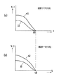
図8から図10は、給紙モータ104および搬送モータ105の減速停止制御時における回転速度Vと印加電流Iの変化を説明するための図である。それらの図において、横軸は時間tであり、縦軸はエンコーダによって検知される回転速度Vと、制御される印加電流Iである。v1とi1は、給紙モータ104の速度と印加電流を示し、v2とi2は、搬送モータ105の速度と印加電流を示す。
FIGS. 8 to 10 are diagrams for explaining changes in the rotational speed V and the applied current I during the deceleration stop control of the
図8は、搬送モータ105の停止時点t0にて給紙モータ104が同時に停止した場合を示す。この図8は理想的な速度変化であり、給紙モータ104と搬送モータ105の停止タイミングが一致し、用紙1は滑らかに協働搬送される。この場合には、図5中のステップS105からステップS106に進むことなく、図5の処理を終了する。
FIG. 8 shows a case where the
図10は、搬送モータ105の停止時点t0において給紙モータ104が停止している場合を示す。図10は、搬送モータ105よりも先に給紙モータ104が停止する場合であり、搬送ローラ105の停止は給紙ローラ104よりも遅い。しかし、搬送ローラ8の搬送力が給紙ローラ3の搬送力よりも大きいため、それらの搬送力の差によって給紙ローラ3と用紙1との間にすべりが発生し、搬送モータ105の駆動には支障がない。したがって、この場合には、図8の理想時な状況と同様に、図5中のステップS105からステップS106に進むことなく、図5の処理を終了する。
FIG. 10 shows a case where the
図9は、給紙モータ104よりも先に搬送モータ105が停止する場合である。例えば、剛性が高い用紙1の搬送中に、このように搬送ローラ105が先に停止した場合には、減速途中の給紙ローラ104によって用紙1を送ることができなくなる。その際、給紙モータ104を含む給紙駆動系に大きな負荷が掛かって、それが動作可能となるおそれがある。したがって、この場合には、図5中のステップS105からステップS106に進み、減速途中にある給紙モータ104の印加電流iをカットして、その給紙ローラ104の減速サーボ制御を中断する。これにより、給紙モータ104は惰性により減速回転しから停止する。
FIG. 9 shows a case where the
このように、図5の処理を実行することにより、給紙モータ104と搬送モータ105の停止タイミングの如何に拘わらず、搬送モータ105の減速停止制御を完了させて、用紙1の停止位置を高精度に管理することができる。
As described above, by executing the processing of FIG. 5, the deceleration stop control of the
図7のように、用紙1を停止させた後は、給紙ローラ3と搬送ローラ8とを同時に駆動し、それらの協働によって、用紙1を記録部6における記録開始位置まで搬送(協働搬送)する。その後、給紙ローラ3と搬送ローラ8との協働による用紙1の間欠的な送り動作を伴って、用紙1に対する画像の記録動作を行なう。図5の処理は、記録装置の如何なる動作中においても実行することができる。つまり、図5の処理は、用紙1の協働搬送中(後述する斜行矯正動作中も含む)に、それらを同時に停止させるときであればいつ実行してもよい。
As shown in FIG. 7, after the paper 1 is stopped, the
(斜行矯正動作)
また、図7のような用紙1の停止に前後して、用紙1の斜行を矯正するための斜行矯正動作を行なうことができる。
(Skew correction)
Further, the skew correction operation for correcting the skew of the paper 1 can be performed before and after the stop of the paper 1 as shown in FIG.
例えば、図7のように用紙1を停止させる前に、搬送ローラ対10のニップ部に、給紙ローラ3の搬送力によって用紙1の先端を押し込むことによって、用紙1の斜行を矯正する。つまり、回転が停止している搬送ローラ8に用紙1の先端を突き当てることによって、斜行を矯正する。斜行矯正動作の他の例としては、給紙ローラ3と搬送ローラ8の協働によって、用紙1の先端を搬送ローラ対10のニップ部に一旦噛ませてから、給紙ローラ3を停止させたまま、搬送ローラ8を逆転させる方法がある。そのときにおける搬送ローラ8の逆転量は、搬送ローラ対10による用紙1の噛み込み量よりも多くする。この方法によれば、用紙1の先端の突き当て時における負荷を軽減し、また用紙1の斜行強制の効果を改善することができる。そして、このように搬送ローラ8の逆転によって用紙1の斜行を矯正してから、その用紙1を記録部6に送る。
For example, as shown in FIG. 7, before the sheet 1 is stopped, the skew of the sheet 1 is corrected by pushing the leading end of the sheet 1 into the nip portion of the conveying
これらの斜行矯正方法は、用紙1の種類などに応じて使い分けられ、また同一の記録装置内においてもローラの回転速度や回転量が変化に対応することができる。 These skew correction methods are properly used according to the type of the paper 1 and the like, and even in the same recording apparatus, the rotation speed and rotation amount of the roller can cope with changes.
(第2の実施形態)
図11は、給紙ローラ3と搬送ローラ8との協働による用紙1の送り(協働搬送)が停止した後の制御を説明するためのフローチャートである。この制御は、用紙1の一連の給紙動作(記録動作時を含む)の制御過程の一部である。
(Second Embodiment)
FIG. 11 is a flowchart for explaining control after the feeding (cooperative conveyance) of the paper 1 by the cooperation of the
図11の処理を開始するステップS501の時点においては、給紙ローラ3と搬送ローラ8は、既に前述した図5のフローチャートに示されるような用紙1の協働搬送を終了している。したがって用紙1は、図7のように、搬送ローラ対10のニップ部に噛み込まれている状態にある。ステップS502は、給紙モータ104および搬送モータ105が一旦停止して、用紙1の協働搬送が終了している状況を示し、次のステップに移る寸前である。
At the time of step S501 in which the processing of FIG. 11 is started, the
次のステップS503においては、給紙ローラ3側の駆動系中におけるエンコーダスリットの検知結果について、前述した減速停止制御が終了してからの変化を判定する。給紙モータ104と搬送モータ105の同時停止後に、給紙ローラ3が正転する方向(用紙1を搬送経路の下流側に搬送する方向)にエンコーダスリットの検知結果が変化した場合、および、それが変化しない場合には、図11の処理を終了する。一方、給紙モータ104と搬送モータ105の同時停止後に、給紙ローラ3が逆転する方向(用紙1を搬送経路の上流側に戻す方向)にエンコーダスリットの検知結果が変化した場合には、ステップS504に進む。ステップS504においては、その後に給紙モータ104と搬送モータ105を駆動する際に、給紙モータ104の駆動開始のタイミングを搬送モータ105よりも早めるように制御する。
In the next step S503, a change in the detection result of the encoder slit in the drive system on the
ステップS504における駆動タイミングのずらし量は、エンコーダスリットによって規定、または、時間によって規定することができる。また、検知される給紙ローラ3の逆転量が大きいときには駆動タイミングのずらし量を大きくするように、給紙ローラ3の逆転量に応じて駆動タイミングのずらし量を調整することもできる。
The shift amount of the drive timing in step S504 can be specified by the encoder slit or can be specified by time. Further, the shift amount of the drive timing can be adjusted in accordance with the reverse rotation amount of the
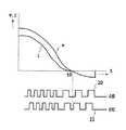
図12および図13は、協働搬送の終了時における給紙モータ104の速度とエンコーダ出力の変化の例を示す。これらの図において、横軸は時間tであり、縦軸は、エンコーダによって検知される給紙モータ3の回転速度vと、制御される印加電流iである。
12 and 13 show examples of changes in the speed of the
エンコーダは回転方向の検知が可能なA相とB相の2チャンネル方式であり、給紙モータ104のエンコーダのA相出力20とB相出力21は、給紙モータ104の速度変化vと比較される。図13は、給紙モータ104の減速停止制御が終了した時点t0において、印加電流iがゼロになった後、給紙モータ104の逆転が発生して、エンコーダ出力が変化した場合を示している。図12は、給紙モータ104の減速停止制御が終了した時点t0において、印加電流がゼロになった後、給紙モータ104の正転が発生して、エンコーダ出力が変化した場合を示している。
The encoder is a two-phase system of phase A and phase B capable of detecting the rotation direction, and the
これらの図12および図13から明らかなように、A相出力20およびB相出力21と、給紙モータ104の速度変化vと、を比較することによって、給紙モータ104の減速停止制御後に給送ローラ3が回転したか否かを判定することができる。さらに、給送ローラ3が回転した場合には、その回転方向を判定することができる。
As apparent from FIGS. 12 and 13, by comparing the
(他の実施形態)
本発明は、記録媒体を搬送するための種々の搬送装置として広く適用することができ、その搬送対象の記録媒体は、画像の記録前のみならず、画像の記録後のものであってもよい。その搬送装置は、記録装置に組み込まれる構成のみならず、記録装置とは別個に構成されるものであってもよい。また、搬送装置が記録装置に組み込まれる場合には、その搬送装置の制御機能の全てまたは一部は、記録装置またはホスト装置にもたせることができる。
(Other embodiments)
The present invention can be widely applied as various conveying devices for conveying a recording medium, and the recording medium to be conveyed may be not only before image recording but also after image recording. . The conveying device is not limited to the configuration incorporated in the recording device, but may be configured separately from the recording device. Further, when the transport apparatus is incorporated in the recording apparatus, all or part of the control function of the transport apparatus can be provided to the recording apparatus or the host apparatus.
また本発明は、シリアルスキャンタイプのインクジェット記録装置のみならず、種々の記録装置に対して広く適用することができる。本発明を適用可能な記録装置としては、例えば、記録媒体の幅方向の全域に渡って延在する長尺な記録ヘッドを定位置に備えて、記録媒体の搬送を伴って画像を記録するフルラインタイプの記録装置を挙げることができる。また、記録方式は、インクジェット記録方式のみに特定されず任意である、熱転写方式などであってもよい。 Further, the present invention can be widely applied not only to a serial scan type ink jet recording apparatus but also to various recording apparatuses. As a recording apparatus to which the present invention can be applied, for example, a full recording head that includes a long recording head extending in the entire width direction of the recording medium at a fixed position and records an image with conveyance of the recording medium is used. A line type recording apparatus can be mentioned. Further, the recording method is not limited only to the ink jet recording method, and may be an arbitrary thermal transfer method.
1 用紙(記録媒体)
3 給紙ローラ(第1のローラ)
6 記録部
7 記録ヘッド
8 搬送ローラ(第2のローラ)
12 紙端センサ
13 DCモータ
14 エンコーダホイール
15 光学センサ
100 CPU
101 ROM
102 RAM
104 給紙モータ(第1の駆動モータ)
105 搬送モータ(第2の駆動モータ)
1 paper (recording medium)
3 Paper feed roller (first roller)
6
12
101 ROM
102 RAM
104 Paper feed motor (first drive motor)
105 Conveyance motor (second drive motor)
Claims (13)
前記第1のローラを第1の駆動モータによって駆動する第1の駆動系と、
前記第2のローラを第2の駆動モータによって駆動する第2の駆動系と、
前記第1および第2のローラの協働による前記記録媒体を搬送中に、前記第1および第2のローラの回転を同時に停止させるように前記第1および第2の駆動モータのそれぞれを減速停止制御可能な制御手段と、
を備え、
前記制御手段は、前記第2のローラの回転が停止したときに前記第1のローラが回転している場合には、前記第1の駆動モータを強制的に停止させる
ことを特徴とする記録媒体の搬送装置。 In a recording medium conveying apparatus for conveying a recording medium through the conveyance path by the cooperation of a first roller located on the upstream side of the conveyance path and a second roller located on the downstream side of the conveyance path,
A first drive system for driving the first roller by a first drive motor;
A second drive system for driving the second roller by a second drive motor;
Each of the first and second drive motors is decelerated and stopped so that the rotations of the first and second rollers are simultaneously stopped during conveyance of the recording medium by the cooperation of the first and second rollers. Controllable control means;
With
The control means forcibly stops the first drive motor when the first roller is rotating when the rotation of the second roller is stopped. Transport device.
ことを特徴とする請求項1に記載の記録媒体の搬送装置。 2. The recording medium conveying apparatus according to claim 1, wherein when the first driving motor is forcibly stopped, the control unit cuts off a driving current of the first driving motor. 3.
ことを特徴とする請求項1または2に記載の記録媒体の搬送装置。 The control means stops the rotation of the first roller when the deceleration stop control for the first drive motor is completed, and the control means stops the deceleration stop control for the second drive motor. 3. The recording medium conveying apparatus according to claim 1, wherein the rotation of the two rollers is stopped.
ことを特徴とする請求項3に記載の記録媒体の搬送装置。 When the first roller is rotating when the rotation of the second roller is stopped, the control means forcibly ends the deceleration stop control for the first drive motor. The recording medium conveying apparatus according to claim 3, wherein the first drive motor is forcibly stopped.
ことを特徴とする請求項3に記載の記録媒体の搬送装置。 The control means completes the deceleration stop control for the second drive motor when the rotation of the first roller stops before the rotation of the second roller stops. The recording medium conveying apparatus according to claim 3.
ことを特徴とする請求項1から6のいずれかに記載の記録媒体の搬送装置。 When the first roller reverses toward the upstream side of the transport path after stopping the first and second drive motors, the control means cooperates with the first and second rollers. The recording according to any one of claims 1 to 6, wherein when the conveyance of the recording medium by operation is resumed, the drive start timing of the first drive motor is made earlier than the second drive motor. Medium transport device.
前記制御手段は、前記検出手段の検出結果に基づいて、前記第1の駆動モータの駆動開始時期を制御することを特徴とする請求項7または8に記載の記録媒体の搬送装置。 A detection means for detecting the rotation amount and rotation direction of the first roller;
9. The recording medium conveying apparatus according to claim 7, wherein the control unit controls a drive start timing of the first drive motor based on a detection result of the detection unit.
前記第1のローラは第1の駆動モータによって駆動し、
前記第2のローラは第2の駆動モータによって駆動し、
前記第1および第2のローラの協働による前記記録媒体を搬送中に、前記第1および第2のローラの回転を同時に停止させるように前記第1および第2の駆動モータのそれぞれを減速停止制御し、
前記第2のローラの回転が停止したときに前記第1のローラが回転している場合には、前記第1の駆動モータを強制的に停止させる
ことを特徴とする記録媒体の搬送方法。 In a recording medium conveyance method of conveying a recording medium through the conveyance path by the cooperation of a first roller located on the upstream side of the conveyance path and a second roller located on the downstream side of the conveyance path,
The first roller is driven by a first drive motor;
The second roller is driven by a second drive motor;
Each of the first and second drive motors is decelerated and stopped so that the rotations of the first and second rollers are simultaneously stopped during conveyance of the recording medium by the cooperation of the first and second rollers. Control
A method for conveying a recording medium, comprising: forcibly stopping the first drive motor if the first roller is rotating when the rotation of the second roller is stopped.
前記搬送経路を通して搬送される記録媒体に対して画像を記録可能な記録部と、
を備えることを特徴とする記録装置。
A recording medium conveying apparatus according to any one of claims 1 to 11,
A recording unit capable of recording an image on a recording medium conveyed through the conveyance path;
A recording apparatus comprising:
Priority Applications (2)
| Application Number | Priority Date | Filing Date | Title |
|---|---|---|---|
| JP2006227180A JP4822984B2 (en) | 2006-08-23 | 2006-08-23 | RECORDING MEDIUM CONVEYING DEVICE, CONVEYING METHOD, AND RECORDING DEVICE |
| US11/840,605 US7591457B2 (en) | 2006-08-23 | 2007-08-17 | Printing medium transport apparatus and method and printing apparatus |
Applications Claiming Priority (1)
| Application Number | Priority Date | Filing Date | Title |
|---|---|---|---|
| JP2006227180A JP4822984B2 (en) | 2006-08-23 | 2006-08-23 | RECORDING MEDIUM CONVEYING DEVICE, CONVEYING METHOD, AND RECORDING DEVICE |
Publications (2)
| Publication Number | Publication Date |
|---|---|
| JP2008050093A JP2008050093A (en) | 2008-03-06 |
| JP4822984B2 true JP4822984B2 (en) | 2011-11-24 |
Family
ID=39112631
Family Applications (1)
| Application Number | Title | Priority Date | Filing Date |
|---|---|---|---|
| JP2006227180A Expired - Fee Related JP4822984B2 (en) | 2006-08-23 | 2006-08-23 | RECORDING MEDIUM CONVEYING DEVICE, CONVEYING METHOD, AND RECORDING DEVICE |
Country Status (2)
| Country | Link |
|---|---|
| US (1) | US7591457B2 (en) |
| JP (1) | JP4822984B2 (en) |
Families Citing this family (3)
| Publication number | Priority date | Publication date | Assignee | Title |
|---|---|---|---|---|
| JP4822984B2 (en) * | 2006-08-23 | 2011-11-24 | キヤノン株式会社 | RECORDING MEDIUM CONVEYING DEVICE, CONVEYING METHOD, AND RECORDING DEVICE |
| JP6402508B2 (en) * | 2014-06-25 | 2018-10-10 | セイコーエプソン株式会社 | Feeding device and recording device |
| JP7328782B2 (en) | 2019-04-05 | 2023-08-17 | キヤノン株式会社 | Recording device and control method |
Family Cites Families (20)
| Publication number | Priority date | Publication date | Assignee | Title |
|---|---|---|---|---|
| JPS59172344A (en) * | 1983-03-22 | 1984-09-29 | Konishiroku Photo Ind Co Ltd | Paper feeding method |
| JP3167676B2 (en) | 1990-04-02 | 2001-05-21 | 株式会社リコー | Image processing device |
| JPH04292355A (en) * | 1991-03-20 | 1992-10-16 | Hitachi Ltd | Sheet orientation control device |
| TW341955U (en) * | 1994-09-30 | 1998-10-01 | Mita Industrial Co Ltd | Device for conveying sheet members |
| DE19781181D2 (en) * | 1996-10-22 | 1999-12-23 | Oce Printing Systems Gmbh | Alignment device |
| JP2001301998A (en) * | 2000-02-15 | 2001-10-31 | Canon Inc | Sheet carrying device, image forming device with the same, and image reading device |
| JP2002332137A (en) * | 2001-05-10 | 2002-11-22 | Canon Inc | Image forming device |
| JP4047562B2 (en) * | 2001-08-31 | 2008-02-13 | リコープリンティングシステムズ株式会社 | Sheet skew correction device and image forming apparatus |
| JP3733944B2 (en) * | 2002-10-31 | 2006-01-11 | ブラザー工業株式会社 | Paper feeder |
| US7334788B2 (en) * | 2003-03-24 | 2008-02-26 | Fuji Xerox Co., Ltd. | Sheet feeder for feeding recording sheets while separating these |
| JP2005001833A (en) * | 2003-06-12 | 2005-01-06 | Fuji Photo Film Co Ltd | Sheet transport device |
| JP2005067805A (en) | 2003-08-25 | 2005-03-17 | Canon Inc | Sheet conveying device and image forming device |
| JP4184904B2 (en) * | 2003-09-03 | 2008-11-19 | 株式会社東芝 | Paper sheet separating and conveying device |
| US7380779B2 (en) * | 2003-10-16 | 2008-06-03 | Canon Kabushiki Kaisha | Sheet processing system |
| JP4185843B2 (en) * | 2003-10-16 | 2008-11-26 | キヤノン株式会社 | Sheet processing system |
| KR100524078B1 (en) * | 2003-11-18 | 2005-10-26 | 삼성전자주식회사 | Automatic document feeding apparatus |
| JP2005320123A (en) * | 2004-05-10 | 2005-11-17 | Canon Inc | Sheet transport device |
| JP2006036490A (en) * | 2004-07-28 | 2006-02-09 | Canon Inc | Conveying device, recording device and conveying control method for recording device |
| JP4371949B2 (en) * | 2004-08-18 | 2009-11-25 | キヤノン株式会社 | Recording medium feeding method and recording apparatus |
| JP4822984B2 (en) * | 2006-08-23 | 2011-11-24 | キヤノン株式会社 | RECORDING MEDIUM CONVEYING DEVICE, CONVEYING METHOD, AND RECORDING DEVICE |
-
2006
- 2006-08-23 JP JP2006227180A patent/JP4822984B2/en not_active Expired - Fee Related
-
2007
- 2007-08-17 US US11/840,605 patent/US7591457B2/en not_active Expired - Fee Related
Also Published As
| Publication number | Publication date |
|---|---|
| US7591457B2 (en) | 2009-09-22 |
| JP2008050093A (en) | 2008-03-06 |
| US20080048383A1 (en) | 2008-02-28 |
Similar Documents
| Publication | Publication Date | Title |
|---|---|---|
| JP4442640B2 (en) | Image forming apparatus | |
| JP6272093B2 (en) | Recording apparatus, control method therefor, program, and storage medium | |
| JP5704862B2 (en) | Sheet conveying apparatus and recording apparatus | |
| JP6366370B2 (en) | RECORDING DEVICE, RECORDING DEVICE CONTROL METHOD, PROGRAM, AND STORAGE MEDIUM | |
| JP2008049557A (en) | Recording apparatus and conveyance controlling method | |
| JP4883776B2 (en) | Recording device | |
| JP6200228B2 (en) | Recording apparatus and control method | |
| JP6381301B2 (en) | Recording apparatus, sheet conveying method, and program | |
| JP2012000897A (en) | Image recording apparatus, and image recording method | |
| JP4822984B2 (en) | RECORDING MEDIUM CONVEYING DEVICE, CONVEYING METHOD, AND RECORDING DEVICE | |
| JP6381323B2 (en) | Recording device | |
| JP2022102562A (en) | Recording device, recording method, storage medium, and program | |
| JP5993842B2 (en) | Recording apparatus and control method | |
| JP6313675B2 (en) | Recording apparatus, control method, and program | |
| JP4371949B2 (en) | Recording medium feeding method and recording apparatus | |
| JP6594491B2 (en) | Recording device | |
| JP2018039233A (en) | Serial type recording device | |
| JP7327009B2 (en) | image recorder | |
| US11805217B2 (en) | Image recording device, method of controlling image recording device, and non-transitory computer-readable recording medium therefor | |
| US9004488B2 (en) | Conveying apparatus and image forming apparatus | |
| US11813852B2 (en) | Printing apparatus and method of controlling the same | |
| US20230311543A1 (en) | Printing apparatus and control method thereof, and storage medium | |
| JP5871517B2 (en) | Transport device and transport control method | |
| JP2009149399A (en) | Recording device and recording medium feed method | |
| JP2017209810A (en) | Recording device, control method and program |
Legal Events
| Date | Code | Title | Description |
|---|---|---|---|
| A621 | Written request for application examination |
Free format text: JAPANESE INTERMEDIATE CODE: A621 Effective date: 20090813 |
|
| RD02 | Notification of acceptance of power of attorney |
Free format text: JAPANESE INTERMEDIATE CODE: A7422 Effective date: 20101106 |
|
| A977 | Report on retrieval |
Free format text: JAPANESE INTERMEDIATE CODE: A971007 Effective date: 20110829 |
|
| TRDD | Decision of grant or rejection written | ||
| A01 | Written decision to grant a patent or to grant a registration (utility model) |
Free format text: JAPANESE INTERMEDIATE CODE: A01 Effective date: 20110902 |
|
| A01 | Written decision to grant a patent or to grant a registration (utility model) |
Free format text: JAPANESE INTERMEDIATE CODE: A01 |
|
| A61 | First payment of annual fees (during grant procedure) |
Free format text: JAPANESE INTERMEDIATE CODE: A61 Effective date: 20110906 |
|
| FPAY | Renewal fee payment (event date is renewal date of database) |
Free format text: PAYMENT UNTIL: 20140916 Year of fee payment: 3 |
|
| LAPS | Cancellation because of no payment of annual fees |