JP5873560B2 - Capping device for print head - Google Patents
Capping device for print head Download PDFInfo
- Publication number
- JP5873560B2 JP5873560B2 JP2014537499A JP2014537499A JP5873560B2 JP 5873560 B2 JP5873560 B2 JP 5873560B2 JP 2014537499 A JP2014537499 A JP 2014537499A JP 2014537499 A JP2014537499 A JP 2014537499A JP 5873560 B2 JP5873560 B2 JP 5873560B2
- Authority
- JP
- Japan
- Prior art keywords
- cap
- capping
- cap station
- station
- Prior art date
- Legal status (The legal status is an assumption and is not a legal conclusion. Google has not performed a legal analysis and makes no representation as to the accuracy of the status listed.)
- Expired - Fee Related
Links
- 238000007639 printing Methods 0.000 claims description 26
- 238000000034 method Methods 0.000 claims description 12
- 239000000758 substrate Substances 0.000 claims description 3
- 230000007246 mechanism Effects 0.000 description 5
- 238000007789 sealing Methods 0.000 description 3
- 238000010586 diagram Methods 0.000 description 2
- 230000015556 catabolic process Effects 0.000 description 1
- 238000004891 communication Methods 0.000 description 1
- 238000006731 degradation reaction Methods 0.000 description 1
- 238000005516 engineering process Methods 0.000 description 1
- 238000009434 installation Methods 0.000 description 1
- 230000000638 stimulation Effects 0.000 description 1
Images


Classifications
-
- B—PERFORMING OPERATIONS; TRANSPORTING
- B41—PRINTING; LINING MACHINES; TYPEWRITERS; STAMPS
- B41J—TYPEWRITERS; SELECTIVE PRINTING MECHANISMS, i.e. MECHANISMS PRINTING OTHERWISE THAN FROM A FORME; CORRECTION OF TYPOGRAPHICAL ERRORS
- B41J2/00—Typewriters or selective printing mechanisms characterised by the printing or marking process for which they are designed
- B41J2/005—Typewriters or selective printing mechanisms characterised by the printing or marking process for which they are designed characterised by bringing liquid or particles selectively into contact with a printing material
- B41J2/01—Ink jet
- B41J2/135—Nozzles
- B41J2/165—Prevention or detection of nozzle clogging, e.g. cleaning, capping or moistening for nozzles
- B41J2/16505—Caps, spittoons or covers for cleaning or preventing drying out
- B41J2/16508—Caps, spittoons or covers for cleaning or preventing drying out connected with the printer frame
- B41J2/16511—Constructions for cap positioning
-
- B—PERFORMING OPERATIONS; TRANSPORTING
- B41—PRINTING; LINING MACHINES; TYPEWRITERS; STAMPS
- B41J—TYPEWRITERS; SELECTIVE PRINTING MECHANISMS, i.e. MECHANISMS PRINTING OTHERWISE THAN FROM A FORME; CORRECTION OF TYPOGRAPHICAL ERRORS
- B41J2/00—Typewriters or selective printing mechanisms characterised by the printing or marking process for which they are designed
- B41J2/005—Typewriters or selective printing mechanisms characterised by the printing or marking process for which they are designed characterised by bringing liquid or particles selectively into contact with a printing material
- B41J2/01—Ink jet
- B41J2/135—Nozzles
- B41J2/165—Prevention or detection of nozzle clogging, e.g. cleaning, capping or moistening for nozzles
- B41J2/16505—Caps, spittoons or covers for cleaning or preventing drying out
- B41J2/16508—Caps, spittoons or covers for cleaning or preventing drying out connected with the printer frame
-
- B—PERFORMING OPERATIONS; TRANSPORTING
- B41—PRINTING; LINING MACHINES; TYPEWRITERS; STAMPS
- B41J—TYPEWRITERS; SELECTIVE PRINTING MECHANISMS, i.e. MECHANISMS PRINTING OTHERWISE THAN FROM A FORME; CORRECTION OF TYPOGRAPHICAL ERRORS
- B41J2/00—Typewriters or selective printing mechanisms characterised by the printing or marking process for which they are designed
- B41J2/005—Typewriters or selective printing mechanisms characterised by the printing or marking process for which they are designed characterised by bringing liquid or particles selectively into contact with a printing material
- B41J2/01—Ink jet
- B41J2/135—Nozzles
- B41J2/165—Prevention or detection of nozzle clogging, e.g. cleaning, capping or moistening for nozzles
- B41J2/16585—Prevention or detection of nozzle clogging, e.g. cleaning, capping or moistening for nozzles for paper-width or non-reciprocating print heads
-
- B—PERFORMING OPERATIONS; TRANSPORTING
- B41—PRINTING; LINING MACHINES; TYPEWRITERS; STAMPS
- B41J—TYPEWRITERS; SELECTIVE PRINTING MECHANISMS, i.e. MECHANISMS PRINTING OTHERWISE THAN FROM A FORME; CORRECTION OF TYPOGRAPHICAL ERRORS
- B41J2/00—Typewriters or selective printing mechanisms characterised by the printing or marking process for which they are designed
- B41J2/005—Typewriters or selective printing mechanisms characterised by the printing or marking process for which they are designed characterised by bringing liquid or particles selectively into contact with a printing material
- B41J2/01—Ink jet
- B41J2/135—Nozzles
- B41J2/165—Prevention or detection of nozzle clogging, e.g. cleaning, capping or moistening for nozzles
- B41J2/16517—Cleaning of print head nozzles
- B41J2/16535—Cleaning of print head nozzles using wiping constructions
- B41J2/16544—Constructions for the positioning of wipers
- B41J2/16547—Constructions for the positioning of wipers the wipers and caps or spittoons being on the same movable support
Landscapes
- Ink Jet (AREA)
- Accessory Devices And Overall Control Thereof (AREA)
Description
背景
プリンタは1つ又は複数のペンを有することがあり、そのようなペンは、ペンの寿命および信頼性を改善するために、及び/又は印刷品質の低下を防止するために、使用中でない場合にキャッピングされ(蓋を被せられ)得る。
Background Printers may have one or more pens, and such pens are not in use to improve pen life and reliability and / or prevent degradation of print quality Can be capped (capped).
幾つかの環境において、プリンタの設置面積(例えば、床面積)は重要な要素となることができる。また、より単純なコンポーネント(構成要素)を提供することは、信頼性の改善および/またはコストの削減につながることもできる。 In some environments, printer footprint (eg, floor area) can be an important factor. Providing simpler components can also improve reliability and / or reduce costs.
本発明の例の目的は、従来技術に関連した1つ又は複数の問題を少なくとも軽減することである。 The purpose of the present example is to at least mitigate one or more problems associated with the prior art.
さて、本発明の例が、添付図面に関連して単なる例示のために説明される。 An example of the present invention will now be described by way of example only with reference to the accompanying drawings.
詳細な説明
幾つかのタイプのプリンタは、印刷媒体が進む方向に対して横切る方向に印刷媒体にわたって前後に移動するプリントヘッドを利用する。しかしながら、プリントヘッドが印刷媒体を横切って移動するのにかなりの時間期間を費やす可能性があるので、印刷媒体にまたがり且つ静止している(即ち、印刷媒体を横切って移動しない)、又は媒体全体に広がり且つ僅かだけ移動することができるプリントヘッドを含むプリンタが開発された。この技術は、ページワイドアレイ(page wide array:PWA)と呼ばれることが多い。PWAプリンタにおいて、プリントヘッドは、印刷媒体の全幅にわたって同時に印刷することができる。一度に1つのスワス(幅帯状区画)だけ印刷媒体の全幅にわたって印刷した後に印刷媒体が進められ、従って、プリントヘッドが印刷媒体に対して横切って移動する必要がないので、印刷速度が改善される。本発明の例はPWAプリンタに関連して説明されるが、理解されるように、印刷媒体を横切って横方向に移動する可動プリントヘッドを含む本発明の例も企図され得る。
DETAILED DESCRIPTION Some types of printers utilize a printhead that moves back and forth across the print media in a direction transverse to the direction in which the print media travels. However, because the print head can spend a significant amount of time moving across the print media, it straddles the print media and is stationary (ie, does not move across the print media), or the entire media Printers have been developed that include print heads that can spread and move only slightly. This technique is often called a page wide array (PWA). In a PWA printer, the print head can print simultaneously across the entire width of the print medium. Printing speed is improved because the print medium is advanced after printing the entire width of the print medium one swath (width strip) at a time, thus eliminating the need for the printhead to move across the print medium. . While the example of the present invention is described in connection with a PWA printer, it will be appreciated that examples of the present invention including a movable printhead that moves laterally across a print medium may also be contemplated.
プリントヘッドのキャッピングは、プリントヘッドの印刷ペンの信頼性を改善するために、印刷ペンを封止するために使用される。本発明の例において、印刷ペンをキャッピングするための複数の印刷キャップを含む印刷キャップステーションが設けられる。キャップステーションは、収縮位置(引っ込んだ位置)とキャッピング位置との間で移動可能である。収縮位置において、キャップステーションは、印刷媒体経路の側部に格納される。本発明の幾つかの例において、キャップステーションは、それぞれがヒンジにより互いに接続された複数の実質的に剛性のキャップモジュールから形成される。収縮位置において、キャップステーションは、印刷媒体経路の側部において折り畳まれる。キャップステーションは、印刷媒体を横方向に横切ってキャップステーションを延ばすことによりキャッピング位置に移動する。キャッピング位置において、プリントヘッドは、キャップステーションと係合することができ、その結果、キャップステーション上に設けられたキャップがプリントヘッドの印刷ペンを封止する。 Printhead capping is used to seal the printing pen to improve the reliability of the printhead's printing pen. In an example of the invention, a print cap station is provided that includes a plurality of print caps for capping a printing pen. The cap station is movable between a retracted position (retracted position) and a capping position. In the retracted position, the cap station is stored on the side of the print media path. In some examples of the invention, the cap station is formed from a plurality of substantially rigid cap modules, each connected to one another by a hinge. In the retracted position, the cap station is folded at the side of the print media path. The cap station moves to the capping position by extending the cap station across the print media in the lateral direction. In the capping position, the print head can engage the cap station so that a cap provided on the cap station seals the print head's printing pen.
さて、本発明の例が、図1に関連して説明される。本発明の例は、各印刷ペンが例えば熱刺激または圧電刺激により、インク滴を吐出するための1つ又は複数のノズルを含むインクジェットプリンタに関連して説明される。しかしながら、理解されるように、印刷ペンがレーザプリンタ又はLEDプリンタを含むトナーを用いたプリンタのような他の技術に基づいている本発明の例も企図され得る。 An example of the present invention will now be described with reference to FIG. Examples of the present invention will be described in connection with an ink jet printer where each printing pen includes one or more nozzles for ejecting ink drops, for example, by thermal or piezoelectric stimulation. However, it will be appreciated that examples of the invention where the printing pen is based on other technologies such as printers using toner including laser printers or LED printers may also be contemplated.
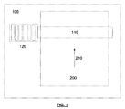
図1は、プリンタ100の全般的な略図である。プリンタ100は、プリントヘッド110の下で、進行方向210に進められる印刷媒体200に印刷するように構成される。図1において、印刷媒体は、個別の用紙、即ち一枚の用紙として示される。また、本発明の例は、ロールから供給されるような、連続した印刷媒体と共に使用され得る。図1の例において、プリントヘッドはページワイドアレイ(PWA)プリントヘッド110であり、そのプリントヘッド110は、印刷媒体200の全幅に広がり、ひいては印刷媒体を横方向に横切って移動する必要がないけれども、横方向に移動することができる本発明の実施形態も企図され得る。このように、プリントヘッドは、印刷媒体200にわたって並んで配列された複数の印刷ペンを含む。
FIG. 1 is a general schematic diagram of a
図1に示されるように、プリントヘッド110に隣接する、印刷媒体200の側部において、キャップステーション120が収縮位置に配置される。収縮位置において、キャップステーションは、プリントヘッド110が印刷媒体に印刷できるように、即ちプリントヘッド110の印刷ペンがキャッピングされないように、プリントヘッドから離れている。キャップステーション120は、使用中でない場合、収縮位置に格納(収容、収納)される。図1に示されたキャップステーション120は、隣接する部分にヒンジを介して接続された複数のほぼ剛性の部分から形成される。ヒンジは、キャップステーションの部分が別個に関節接合されることを可能にする且つキャップステーション120が収縮位置で折り畳まれることを可能にするために、キャップステーションの部分の両端に配置される。キャップステーションは、コンサーティーナ又はアコーディオンのようにヒンジを中心として折り畳まれ、従って、キャップステーション120の必要な収納スペースが低減される。即ち、折り畳まれた場合、第1及び第2の部分を接続するヒンジは下端に配置され、一方、第2及び第3の部分を接続するヒンジは上端などに配置される。キャップステーションの各部分の表面が、プリントヘッド110の1つ又は複数の印刷ペンを封止するための1つ又は複数のキャップを担持するように構成される。キャップは、例えば個々の印刷ペンの周りで封止するための、突出するリム(外周部)を有するゴムキャップとして形成され得るが、本発明の実施形態はこの態様に制限されない。
As shown in FIG. 1, on the side of the
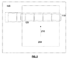
キャップステーションは、図1に示された収縮位置と図2に示されたキャッピング位置との間で駆動され得るように、動かせるように構成される。図2は、プリントヘッドの下にとどまっている印刷媒体200を示すが、一般にキャップステーションは、印刷媒体が存在しない場合にキャッピング位置に移動することは理解されるであろう。
The cap station is configured to be movable so that it can be driven between the retracted position shown in FIG. 1 and the capping position shown in FIG. Although FIG. 2 shows the
キャッピング位置において、キャップステーションは、プリントヘッドの下で横方向に印刷媒体経路を横切って延びる。キャッピング位置において、キャップステーション120の部分の少なくとも大半は、プリントヘッド110の下側の印刷ペンがキャップステーション120の上面(キャッピング位置にいる場合)に位置するキャップと接触することができるように、一般に水平方向に配列される。幾つかの例において、キャップステーション120又はそれに取り付けられたキャップは、印刷ペンに係合するために垂直方向に移動可能とすることができる。しかしながら、本発明の他の例において、キャップステーション120は、プリントヘッド110が印刷媒体200から離れるように垂直に上方へ移動することにより、印刷媒体200の表面に近接した印刷位置から引き戻される際に、収縮位置とキャッピング位置との間で移動するように構成される。キャップステーション120がキャッピング位置に配置される場合、プリントヘッド110は、キャップステーション上のキャップがプリントヘッド110の下側の印刷ペンに係合してキャッピングするような所定の力でもって、例えば下向き方向にキャップステーション120の方に移動することができる。プリントヘッド又はペンの下向きの動き、又はキャップステーション120上のキャップの上向きの動きの結果として、キャップは、少なくとも部分的に印刷ペンを覆い、それにより印刷ペンに当接して封止する。
In the capping position, the cap station extends across the print media path laterally under the print head. In the capping position, at least most of the portion of the
キャップステーション120は、図1に示された収縮位置と図2に示されたキャッピング位置との間で、多数の方法で駆動され(動かされ)得る。幾つかの例において、キャップステーション120は、図3及び図4に関連して更に説明されるように、印刷媒体200を横切って延び且つプーリー上で動作する推進ケーブルに取り付けられることができ、キャップステーションは、プーリー上の推進ケーブルの動きにより、収縮位置とキャッピング位置との間で移動するようになっている。キャップステーションに支持体を提供するために、キャップステーションの部分が案内されて支持されるキャップステーションレールが設けられる。
The
図3は、本発明の例を斜視図で示す。図3及び図4に示されたプリンタ300は、収縮位置に配置されたキャップステーション350を含む。
FIG. 3 shows an example of the present invention in a perspective view. The printer 300 shown in FIGS. 3 and 4 includes a
プリンタ300は、プリントヘッド310を含み、収縮位置にあるキャップステーション350に最も近いプリントヘッドの端部のみが示される。図1及び図2に関連して前述されたように、プリントヘッドは印刷媒体を横切って延在するPWAプリントヘッドである。プリントヘッド310は、プリントバー330上に支持される。プリントバー330は、ラックアンドピニオン機構を動かすように構成されたステッピングモータを含むことができるプリントバーエレベータ機構315により、垂直方向に移動可能であるが、プリントバーを動かすための他の機構も企図され得る。プリントバー330の
垂直運動の結果として、それに支持されたプリントヘッド310も垂直に移動する。より低い位置において、プリントヘッド310は、印刷媒体に印刷するために印刷媒体に近接して位置する。
The printer 300 includes a
キャップステーションは、複数の部分351、352、353により形成され、明瞭化のために、それらの全てが付番されているわけではない。キャップステーションの部分351、352、353はそれぞれ、実質的に剛性であり、一般に細長い。第1のキャップステーションの部分は、ほぼ水平方向に収縮位置に懸架され、キャップステーションガイド370上に支持される。第1のキャップステーションの部分は、推進ケーブル340に取り付けられ、推進ケーブル340はプリンタの両側に配置された第1及び第2のプーリー上で動く。第1のキャップステーションの部分351は、推進ケーブル340により、収縮位置におけるプリンタ300の第1の側からキャッピング位置におけるプリンタ300の第2の側まで移動可能である。収縮位置において、第1のキャップステーションの部分351は、キャップステーションガイド370上に懸架される。第1のキャップステーションの部分351がプリンタの対向する第2の側に進む際、それは、キャップステーションガイドにより支持されている所からプリントバー330上に支持されている所に移動する。第1のキャップステーションの部分351が推進ケーブル340により移動する際、それは、プリントヘッド310に近接してキャップステーションガイド370に形成されたレールの開放端から出る。第1のキャップステーションの部分351は、プリントヘッド310の下にあるプリントバー上に支持されるために、プリントバーキャップガイド320の開放端に入る。第1のキャップの部分は、推進ケーブル340により、プリントバーキャップガイド320に沿ってプリンタ300の第2の側の方へ移動し続ける。
The cap station is formed by a plurality of
第2のキャップステーションの部分352、第3のキャップステーションの部分353及び更なるキャップステーションの部分は、水平方向に積み重ねられ(スタックされ)た構成でほぼ垂直方向に配列されている収縮位置から、プリントバーキャップガイドにより支持され且つ最も端のキャップステーションの部分(単数または複数)の場合にキャップステーションガイド370上に支持されるキャッピング位置まで移動する。第1のキャップステーションの部分351が収縮位置から離れて移動する際、第2のキャップステーションの部分352が、キャップステーションの部分351と352との間に位置する第1のヒンジ361によって引っ張られる。コンサーティーナを伸ばすように、第2のキャップステーションの部分は、第1のキャップステーションの部分351から加えられたけん引力によって、垂直構成から水平構成に徐々に移動する。同様に、第3のキャップステーションの部分353、及び更なるキャップステーションの部分も徐々に、水平位置に移動してプリントバーキャップガイド320に沿って進み、プリントヘッド310の下に広がる。
The second
前述したように、キャップステーションの部分351、352、353は、キャッピング位置にある際に上側となる第1の側にキャップを担持する。キャップステーションがプリンタ300にわたって広がることを可能にするために、プリントヘッド310は、プリントバーエレベータ機構315により上向き方向に移動する。次いで、キャップステーション350は、推進ケーブル340により収縮位置からキャッピング位置まで移動する。ひとたびキャッピング位置になると、キャップステーション350は、プリントヘッド310の下に広がる。キャップステーション350上に担持されたキャップは一般に、プリントヘッド310の印刷ペンと垂直方向に位置合わせされ、プリントヘッド310がプリントバーエレベータ機構315により下方に下げられた際に、印刷ペンがキャップステーション350上の対応するキャップに係合して、それにより印刷ペンをキャッピングするようになっている。印刷ペンのキャッピングを解除するために、プリントバーが上方に移動し、それによりキャップと印刷ペンを切り離し、その後、キャップステーションは推進ケーブル340の反対の動きにより収縮位置に移動する。キャップステーション350がキャッピング位置から収縮位置まで移動する際、キャップステーションの部分351、352、353は一般に、ヒンジ361を中心として回転することによってキャッピング位置の水平構成から収縮位置の垂直構成に移行することにより、ぺしゃんこになる。理解されるように、第1のキャップステーションの部分351のようなキャップステーションの部分の一部は、収縮位置において依然として水平構成、又は水平と垂直との間の構成のままであることができる。しかしながら、幾つかの例において、大半のキャップステーションの部分352、353は、収縮位置において水平方向に積み重ねられた構成に配列される。
As described above, the
キャップステーションの他の構成を構想することができることを理解するであろう。一例において、収縮位置において、キャップステーションは、キャッピング位置にいる際にキャップステーションが配列される水平面の上方へ又は下方へ垂直の向きに配列され得る。例えば、キャップステーションは、推進ケーブルによって、プリンタの第1の側の方へ移動することができ、この場合、キャップステーションの部分は、プリンタの当該側において垂直方向に下向きに円弧を通じて移動する。一例において、キャップステーションは、プリンタのレグにおける収縮位置に配列され得る。また、キャップステーションの部分は、プリンタの第1の側において垂直方向に積み重ねられた構成へとぺしゃんこにされ得る。別の例において、キャップステーションの部分は、プリンタの第1の側に位置するドラムに巻き付けられるように配列され得る。幾つかの例において、キャップステーションは、その上に印刷ペンのキャップを担持するフレキシブルな基板とすることができる。 It will be appreciated that other configurations of the cap station can be envisioned. In one example, in the retracted position, the cap station may be arranged in a vertical orientation above or below the horizontal plane in which the cap station is arranged when in the capping position. For example, the cap station can be moved toward the first side of the printer by means of a propulsion cable, in which case the portion of the cap station moves down the arc vertically downward on that side of the printer. In one example, the cap station can be arranged in a retracted position on the leg of the printer. Also, the portion of the cap station can be pegged into a vertically stacked configuration on the first side of the printer. In another example, the portion of the cap station may be arranged to wrap around a drum located on the first side of the printer. In some examples, the cap station may be a flexible substrate carrying a printing pen cap thereon.
図3の例において、キャップステーションは、キャッピング位置でプリントバー330上に支持されるが、他の構成も可能である。例えば、キャップステーションをキャッピング位置に懸架および/または案内するためのキャップステーション梁が設けられ得る。
In the example of FIG. 3, the cap station is supported on the
有利な点は、本発明の実施形態は、プリントバーの設置面積(実装面積)を低減することができる。キャップステーションがキャッピング位置において、プリントバー上に支持される場合、幾つかの実施形態において、更なる支持バーを必要としないことができる。これは、大きな印刷媒体の上に広がるプリントバーが最大の曲がり仕様を満たすように設計することが困難である可能性があるので、大型のプリンタにおいて特に有用であるかもしれない。 As an advantage, the embodiment of the present invention can reduce the installation area (mounting area) of the print bar. If the cap station is supported on the print bar in the capping position, in some embodiments, no additional support bar may be required. This may be particularly useful in large printers because it may be difficult to design a print bar that extends over a large print medium to meet the maximum bend specification.
本発明の実施形態が、ハードウェア、ソフトウェア、又はハードウェアとソフトウェアの組み合わせの形態で実現され得ることは理解されるであろう。任意のそのようなソフトウェアは、例えば、消去可能か又は書換可能か又はそうでないROMのような記憶デバイスのような揮発性または不揮発性の記憶装置の形態で格納され得る、又は例えばRAM、メモリチップ、デバイス又は集積回路のようなメモリの形態で格納され得る、又は例えばCD、DVD、磁気ディスク又は磁気テープのような光学的または磁気的に読み出し可能な媒体に格納され得る。理解されるように、記憶デバイス及び記憶媒体は、実行された際に本発明の実施形態を実施するプログラム(単数または複数)を格納するのに適した機械可読記憶装置の実施形態である。従って、実施形態は、特許請求の範囲に記載されたようなシステム又は方法を実施するためのコードを含むプログラム、及びそのようなプログラムを格納する機械可読記憶装置を提供する。更に、本発明の実施形態は、有線接続または無線接続を介して伝送される通信信号のような任意の媒体を介して電子的に伝えられることができ、実施形態は適切にそのようなものを包含する。 It will be appreciated that embodiments of the invention may be implemented in the form of hardware, software, or a combination of hardware and software. Any such software may be stored in the form of a volatile or non-volatile storage device, such as a storage device such as a ROM, for example erasable or rewritable or not, or for example a RAM, a memory chip Can be stored in the form of a memory, such as a device or an integrated circuit, or can be stored on an optically or magnetically readable medium such as a CD, DVD, magnetic disk or magnetic tape. As will be appreciated, the storage device and storage medium are embodiments of machine-readable storage devices suitable for storing program (s) that, when executed, implement the embodiments of the invention. Accordingly, embodiments provide a program that includes code for implementing a system or method as recited in the claims, and a machine-readable storage device that stores such a program. Furthermore, embodiments of the present invention can be communicated electronically via any medium, such as a communication signal transmitted via a wired or wireless connection, and embodiments appropriately Include.
任意の形態の印刷ペンが、本発明の実施形態に関連して使用され得る。本明細書で使用されるような用語ペンは、使用中でない場合にキャップ又は蓋が取り付けられ得る任意の形態の印刷ノズル、液滴生成器、イメージ生成器、又はプリンタの塗布器を含む。 Any form of printing pen may be used in connection with embodiments of the present invention. The term pen as used herein includes any form of print nozzle, drop generator, image generator, or printer applicator to which a cap or lid can be attached when not in use.
上、下、及び水平のような向きに対する言及は、説明の便宜のためであり、他の向きも使用され得る。 References to orientations such as top, bottom, and horizontal are for convenience of explanation and other orientations may be used.
本明細書(添付の特許請求の範囲、要約および図面の全てを含む)に開示された特徴要素の全て、及び/又はそのように開示された任意の方法またはプロセスのステップの全ては、少なくともそのような特徴要素および/またはステップの一部が相互に排他的である場合の組み合わせを除いて、任意の組み合わせで組み合わせられ得る。 All of the features disclosed in this specification (including all of the appended claims, abstract and drawings) and / or all of the steps of any method or process so disclosed are at least Such features and / or steps may be combined in any combination, except combinations where some of the steps are mutually exclusive.
特許請求の範囲は、前述の実施形態だけでなく、特許請求の範囲内にある任意の実施形態も網羅するように構成されている。 The claims are configured to cover not only the embodiments described above, but also any embodiment within the scope of the claims.
Claims (15)
1つ又は複数のキャップを担持するキャップステーションを含み、前記キャップステーションは、それぞれがヒンジにより互いに接続された複数のキャップモジュールから形成され、前記キャップステーションは、前記キャップステーションが印刷媒体経路の側部に折り畳まれて格納される収縮位置と、前記キャップステーションが前記プリントヘッドの下で前記印刷媒体経路を横方向に横切って延び、前記プリントヘッドをキャッピングするためのキャッピング位置との間で移動可能である、キャッピング装置。 A key Yappingu device printhead of the printer,
A cap station carrying one or more caps, the cap station being formed from a plurality of cap modules each connected to each other by hinges, the cap station being a side of the print media path; a contracted position that will be stored folded, extends the print media path under the cap station said printhead across laterally movable between a capping position for capping the print head there, key Yappingu device.
1つ又は複数のキャップを担持するキャップステーションを含み、前記キャップステーションが、複数のキャップモジュールから形成され、前記キャップステーションは、前記キャップステーションが前記印刷媒体経路の側部において巻かれて格納される収縮位置と、前記キャップステーションが前記プリントヘッドの下で前記印刷媒体経路を横方向に横切って延び、前記プリントヘッドをキャッピングするためのキャッピング位置との間で移動可能である、キャッピング装置。 A capping device for a print head of a printer,
Includes a cap station carrying one or more caps, the cap station is formed from a plurality of caps module, before Symbol cap station, the cap station are stored wound at the side of the print media path that a retracted position, extending across the print medium path the cap station under the printhead in the transverse direction, is movable between a capping position for capping the print head, key Yappingu device.
プリントヘッドと、
請求項1〜8の何れかに記載されたキャッピング装置と、
前記プリントヘッドを支持するように構成されたプリント支持部材と、
前記キャッピング装置を支持するように構成されたキャップ支持部材とを含み、
前記プリント支持部材が、前記印刷媒体経路に対して実質的に垂直に移動可能であり、前記キャップ支持部材が、前記印刷媒体経路に対して垂直な方向に移動不可能である、印刷装置。 A printing device,
A printhead ;
A capping device according to any one of claims 1 to 8 ,
A print support member configured to support the printhead;
A cap support member configured to support the capping device;
The print support member is substantially perpendicular movable relative to the print medium path, said cap supporting member is a unmovable in a direction perpendicular to the print medium path, a printing device.
第1の位置と第2の位置との間でキャッピング装置を移動することを含み、
前記キャッピング装置は、それぞれがヒンジにより互いに接続された複数のキャップモジュールから形成され、
前記第1の位置において、前記キャッピング装置が前記プリンタのプリントヘッドをキャッピングするために印刷媒体経路を横切って広がり、
前記第2の位置において、前記キャッピング装置が前記印刷媒体経路の側部に折り畳まれて格納されている、方法。 A method of capping a print head of a printer,
Moving the capping device between a first position and a second position;
The capping device is formed from a plurality of cap modules each connected to each other by a hinge,
In the first position, the capping device extends across a print media path to capping the print head of the printer;
The method wherein, in the second position, the capping device is folded and stored on a side of the print media path.
第1の位置と第2の位置との間でキャッピング装置を移動することを含み、Moving the capping device between a first position and a second position;
前記キャッピング装置が、複数のキャップモジュールから形成され、The capping device is formed of a plurality of cap modules;
前記第1の位置において、前記キャッピング装置が前記プリンタのプリントヘッドをキャッピングするために印刷媒体経路を横切って広がり、In the first position, the capping device extends across a print media path to capping the print head of the printer;
前記第2の位置において、前記キャッピング装置が前記印刷媒体経路の側部において巻かれて格納されている、方法。The method wherein, in the second position, the capping device is wound and stored on the side of the print media path.
前記プリントヘッドでもって前記印刷媒体上に印刷することを含み、
前記移動することが、前記通過させること及び前記印刷することの前または後の少なくとも一方で実行される、請求項10〜14の何れかに記載の方法。 Passing the print medium along the print medium path;
Printing on the print medium with the print head ,
The method according to claim 10, wherein the moving is performed at least one of before and after the passing and printing.
Applications Claiming Priority (1)
| Application Number | Priority Date | Filing Date | Title |
|---|---|---|---|
| PCT/EP2011/069149 WO2013064168A1 (en) | 2011-10-31 | 2011-10-31 | Print pen capping apparatus |
Publications (2)
| Publication Number | Publication Date |
|---|---|
| JP2014530781A JP2014530781A (en) | 2014-11-20 |
| JP5873560B2 true JP5873560B2 (en) | 2016-03-01 |
Family
ID=44883285
Family Applications (1)
| Application Number | Title | Priority Date | Filing Date |
|---|---|---|---|
| JP2014537499A Expired - Fee Related JP5873560B2 (en) | 2011-10-31 | 2011-10-31 | Capping device for print head |
Country Status (6)
| Country | Link |
|---|---|
| US (2) | US20140300664A1 (en) |
| EP (1) | EP2773507B1 (en) |
| JP (1) | JP5873560B2 (en) |
| CN (1) | CN103906628B (en) |
| BR (1) | BR112014010373B1 (en) |
| WO (1) | WO2013064168A1 (en) |
Families Citing this family (3)
| Publication number | Priority date | Publication date | Assignee | Title |
|---|---|---|---|---|
| WO2013064168A1 (en) * | 2011-10-31 | 2013-05-10 | Hewlett-Packard Development Company, L.P. | Print pen capping apparatus |
| JP6095542B2 (en) * | 2013-09-27 | 2017-03-15 | 富士フイルム株式会社 | Droplet discharge device |
| WO2016170383A1 (en) | 2015-04-24 | 2016-10-27 | Hewlett-Packard Development Company, L.P. | Print bar for a multi-pass printer and multi-pass page-wide-array printer |
Family Cites Families (25)
| Publication number | Priority date | Publication date | Assignee | Title |
|---|---|---|---|---|
| JPH02184453A (en) * | 1989-01-11 | 1990-07-18 | Canon Inc | Ink jet recorder |
| US5635965A (en) * | 1995-01-31 | 1997-06-03 | Hewlett-Packard Company | Wet capping system for inkjet printheads |
| GB9908099D0 (en) * | 1999-04-12 | 1999-06-02 | Gay Geoffrey N W | Air cleaning collection device |
| US6328411B1 (en) * | 1999-10-29 | 2001-12-11 | Hewlett-Packard Company | Ferro-fluidic inkjet printhead sealing and spitting system |
| JP4790107B2 (en) * | 2000-10-13 | 2011-10-12 | オリンパス株式会社 | Printer |
| JP4126900B2 (en) * | 2001-11-26 | 2008-07-30 | セイコーエプソン株式会社 | Inkjet printer head maintenance mechanism |
| JP3828411B2 (en) * | 2001-11-30 | 2006-10-04 | オリンパス株式会社 | Image forming apparatus |
| US6733106B1 (en) * | 2002-10-24 | 2004-05-11 | Lexmark International, Inc. | Ink jet maintenance station with radial orientation |
| JP3991900B2 (en) * | 2003-03-27 | 2007-10-17 | ブラザー工業株式会社 | Print head cap |
| GB0308203D0 (en) * | 2003-04-09 | 2003-05-14 | Hewlett Packard Co | Servicing printheads |
| JP3982519B2 (en) * | 2004-05-28 | 2007-09-26 | ブラザー工業株式会社 | Inkjet recording device |
| US7364256B2 (en) * | 2004-12-06 | 2008-04-29 | Silverbrook Research Pty Ltd | Inkjet printer with capping mechanism |
| JP4614840B2 (en) * | 2005-07-25 | 2011-01-19 | 株式会社リコー | Image forming apparatus |
| TWI273037B (en) * | 2005-10-25 | 2007-02-11 | Benq Corp | Ink jet printing apparatus and protecting structure of printing cartridge thereof |
| US7766449B2 (en) * | 2006-03-27 | 2010-08-03 | Brother Kogyo Kabushiki Kaisha | Ink-jet recording apparatus |
| JP4932552B2 (en) * | 2007-03-19 | 2012-05-16 | 理想科学工業株式会社 | Image forming apparatus equipped with maintenance mechanism |
| JP2008246879A (en) * | 2007-03-30 | 2008-10-16 | Brother Ind Ltd | Image recording device |
| JP4872849B2 (en) * | 2007-08-02 | 2012-02-08 | セイコーエプソン株式会社 | Fluid ejection device |
| JP2009045900A (en) * | 2007-08-22 | 2009-03-05 | Seiko Epson Corp | Liquid jet apparatus |
| JP2009125964A (en) * | 2007-11-20 | 2009-06-11 | Kyocera Mita Corp | Inkjet image forming apparatus |
| CN101746144B (en) * | 2008-12-16 | 2014-07-16 | 精工爱普生株式会社 | Fluid ejecting apparatus and maintenance method of fluid ejecting apparatus |
| JP5187857B2 (en) * | 2009-11-30 | 2013-04-24 | 株式会社東京機械製作所 | Ink receiving device for inkjet printer |
| JP5361765B2 (en) * | 2010-02-26 | 2013-12-04 | キヤノン株式会社 | Printing apparatus, printing method, and sheet processing method |
| JP5482314B2 (en) * | 2010-03-10 | 2014-05-07 | 株式会社リコー | Image forming apparatus |
| WO2013064168A1 (en) * | 2011-10-31 | 2013-05-10 | Hewlett-Packard Development Company, L.P. | Print pen capping apparatus |
-
2011
- 2011-10-31 WO PCT/EP2011/069149 patent/WO2013064168A1/en active Application Filing
- 2011-10-31 US US14/351,999 patent/US20140300664A1/en not_active Abandoned
- 2011-10-31 CN CN201180074593.0A patent/CN103906628B/en not_active Expired - Fee Related
- 2011-10-31 BR BR112014010373-9A patent/BR112014010373B1/en not_active IP Right Cessation
- 2011-10-31 EP EP11776212.0A patent/EP2773507B1/en active Active
- 2011-10-31 JP JP2014537499A patent/JP5873560B2/en not_active Expired - Fee Related
-
2016
- 2016-04-01 US US15/089,199 patent/US9776414B1/en not_active Expired - Fee Related
Also Published As
| Publication number | Publication date |
|---|---|
| BR112014010373B1 (en) | 2020-07-07 |
| EP2773507B1 (en) | 2020-03-04 |
| WO2013064168A1 (en) | 2013-05-10 |
| BR112014010373A2 (en) | 2017-04-25 |
| CN103906628A (en) | 2014-07-02 |
| CN103906628B (en) | 2016-11-09 |
| JP2014530781A (en) | 2014-11-20 |
| US20140300664A1 (en) | 2014-10-09 |
| EP2773507A1 (en) | 2014-09-10 |
| US9776414B1 (en) | 2017-10-03 |
Similar Documents
| Publication | Publication Date | Title |
|---|---|---|
| JP6386558B2 (en) | Modular printer with narrow printing area | |
| JP4274180B2 (en) | Inkjet recording device | |
| JP5783868B2 (en) | Printing mechanism used in ink printing equipment | |
| JP5873560B2 (en) | Capping device for print head | |
| US9296206B2 (en) | Print group for an ink printing apparatus | |
| US20110242195A1 (en) | Ink-Jet Recording Apparatus | |
| JP6122124B2 (en) | Printing system services | |
| US8240842B2 (en) | Ink-jet recording apparatus | |
| CN104070795B (en) | Tape deck | |
| CN106042667A (en) | Printer | |
| JP6402963B2 (en) | Image recording device | |
| JP2020011401A (en) | Inkjet printer and method for controlling inkjet printer | |
| US7926903B2 (en) | Ink-jet recording apparatus | |
| JP5863580B2 (en) | Inkjet head maintenance apparatus and inkjet recording apparatus | |
| CN112888570B (en) | Capping unit, maintenance device, and printer | |
| US9471099B2 (en) | Container, image forming apparatus, and electronic device | |
| US20100128098A1 (en) | Inkjet printer | |
| JP7512587B2 (en) | Liquid ejection device | |
| JP2011051272A (en) | Carriage and recorder | |
| JP5932266B2 (en) | Inkjet recording device | |
| US8678536B2 (en) | Printing device and printing method | |
| JP5948311B2 (en) | Cap device and inkjet printer | |
| CN115703295A (en) | Liquid ejecting apparatus | |
| JP2007160552A (en) | Ink supply unit and inkjet recording apparatus | |
| JP2009214453A (en) | Image forming apparatus |
Legal Events
| Date | Code | Title | Description |
|---|---|---|---|
| A621 | Written request for application examination |
Free format text: JAPANESE INTERMEDIATE CODE: A621 Effective date: 20140428 |
|
| A977 | Report on retrieval |
Free format text: JAPANESE INTERMEDIATE CODE: A971007 Effective date: 20150312 |
|
| A131 | Notification of reasons for refusal |
Free format text: JAPANESE INTERMEDIATE CODE: A131 Effective date: 20150317 |
|
| A521 | Request for written amendment filed |
Free format text: JAPANESE INTERMEDIATE CODE: A523 Effective date: 20150604 |
|
| A131 | Notification of reasons for refusal |
Free format text: JAPANESE INTERMEDIATE CODE: A131 Effective date: 20150707 |
|
| A521 | Request for written amendment filed |
Free format text: JAPANESE INTERMEDIATE CODE: A523 Effective date: 20150928 |
|
| TRDD | Decision of grant or rejection written | ||
| A01 | Written decision to grant a patent or to grant a registration (utility model) |
Free format text: JAPANESE INTERMEDIATE CODE: A01 Effective date: 20160112 |
|
| A61 | First payment of annual fees (during grant procedure) |
Free format text: JAPANESE INTERMEDIATE CODE: A61 Effective date: 20160115 |
|
| R150 | Certificate of patent or registration of utility model |
Ref document number: 5873560 Country of ref document: JP Free format text: JAPANESE INTERMEDIATE CODE: R150 |
|
| R250 | Receipt of annual fees |
Free format text: JAPANESE INTERMEDIATE CODE: R250 |
|
| R250 | Receipt of annual fees |
Free format text: JAPANESE INTERMEDIATE CODE: R250 |
|
| LAPS | Cancellation because of no payment of annual fees |