JP5871361B2 - Method for manufacturing a railway vehicle structure - Google Patents
Method for manufacturing a railway vehicle structure Download PDFInfo
- Publication number
- JP5871361B2 JP5871361B2 JP2011145641A JP2011145641A JP5871361B2 JP 5871361 B2 JP5871361 B2 JP 5871361B2 JP 2011145641 A JP2011145641 A JP 2011145641A JP 2011145641 A JP2011145641 A JP 2011145641A JP 5871361 B2 JP5871361 B2 JP 5871361B2
- Authority
- JP
- Japan
- Prior art keywords
- panel
- plate
- curtain
- blowing
- waist
- Prior art date
- Legal status (The legal status is an assumption and is not a legal conclusion. Google has not performed a legal analysis and makes no representation as to the accuracy of the status listed.)
- Expired - Fee Related
Links
Images


Description
本発明は、外板にシアプレートを接合することなく吹寄部の強度を高めた鉄道車両用構体に関する。 The present invention relates to a railway vehicle structure in which the strength of a blowing portion is increased without joining a shear plate to an outer plate.
鉄道車両用構体は、例えば図4に示すように、側構体が構体ブロックなどのパーツを接合して組み合わされたものがある。鉄道車両用構体は、そうした側構体の上部に屋根構体が、前後には妻構体がそれぞれ接合され、更にその下には台枠が接合して構成される。図示する側構体100は、車端窓ブロック102と中間窓ブロック103、そして窓ブロック102,103の間に側入口ブロック104が接合されている。
For example, as shown in FIG. 4, there is a railway vehicle structure in which a side structure is combined by joining parts such as a structure block. The structure for a railway vehicle is constructed by joining a roof structure at the upper part of such a side structure, a wife structure at the front and rear, and a base frame below it. In the illustrated
車端窓ブロック102や中間窓ブロック103は、例えば上下に分けられた上部外板と下部外板との接合によって側外板が形成され、その車体内側には強度を保つため骨部材などが接合されている。そして、中間窓ブロック103は、せん断力のかかりやすい吹寄部に、補強部材としてシアプレート110が外板の裏面に張り合わされている。このシアプレート110は、例えば板厚2mmの外板に対し、厚さ1.5mmのステンレス鋼板であって、窓開口部120の左右両側の吹寄部にそれぞれ配置されている。
In the vehicle
従来の鉄道車両用構体は、吹寄部の強度をシアプレート110によって確保しているが、そのシアプレート110は、中間窓ブロック103を構成する外板の裏面に重ねられ、レーザ溶接等によって接合される。その際、吹寄部の強度を確保するにはシアプレート110が外板に対して全体的に接合している必要があり、溶接箇所はシアプレート110の全面に及ぶため、レーザ溶接の溶接距離が長くなってしまう。従って、従来の鉄道車両用構体は、シアプレート110を取り付けるため構造が複雑になって作業工数が増すばかりではなく、その溶接作業自体も手間のかかるものであった。
In the conventional railcar structure, the strength of the blowing portion is secured by the
本発明は、かかる課題を解決すべく、シアプレートを接合することなく吹寄部の強度を高めた鉄道車両用構体を提供することを目的とする。 In order to solve this problem, an object of the present invention is to provide a railway vehicle structure in which the strength of a blowing portion is increased without joining a shear plate.
本発明に係る鉄道車両用構体の製造方法は、側構体、屋根構体、妻構体および台枠が接合され、前記側構体は、車体長手方向に分割された複数のブロックの接合により構成された鉄道車両用構体の製造方法において、前記側構体を構成する窓ブロックは、幕板パネル、吹寄パネルおよび腰板パネルを含み、前記吹寄パネルは、当該窓ブロックに形成される窓開口部の窓隅部を含むものであり、前記幕板パネルおよび腰板パネルよりも高強度の板材であり、前記幕板パネルおよび腰板パネルは凸形状の板材であり、前記吹寄パネルは四角形状の板材であり、前記幕板パネルおよび腰板パネルの左右の凹んだ部分に前記吹寄パネルを配置する配置工程と、前記幕板パネル、吹寄パネルおよび腰板パネルの端面同士を突き合わせた接合部をレーザ溶接する接合工程と、接合後に前記吹寄パネルの一部のみが切り取られることにより前記窓開口部を形成する切り取り工程と、を有することを特徴とする。
また、前記吹寄パネルは、前記幕板パネルおよび腰板パネルと同じ材料の板材であって板厚が前記幕板パネルおよび腰板パネルよりも厚いものであること、又は前記幕板パネルおよび腰板パネルと同じ板厚であって前記幕板パネルおよび腰板パネルよりも高強度の材料の板材であることを特徴とする。
In the method for manufacturing a railway vehicle structure according to the present invention, a side structure, a roof structure, a wife structure, and a base frame are joined, and the side structure is configured by joining a plurality of blocks divided in the longitudinal direction of the vehicle body. In the method for manufacturing a vehicle structure , the window block forming the side structure includes a curtain panel, a blowing panel, and a waist panel , and the blowing panel is a window corner of a window opening formed in the window block. is intended to include a section, sheet der high strength than the curtain panels and wainscot panels is, the curtain panels and wainscot panels are plates of convex, the吹寄panel is a square-shaped plate the curtain plate panels and an arrangement step of arranging said吹寄panel recessed portion of the left and right wainscot panels, the curtain panels, laser soluble junction of matching the end faces of the 吹寄panel and wainscot panel And having a bonding step for, and a cut forming the window opening by only a portion of the吹寄panel after bonding is cut.
Further, the blowing panel is a plate material made of the same material as the curtain plate panel and the waist plate panel, and is thicker than the curtain plate panel and the waist plate panel, or the curtain panel and the waist plate panel It is the board | plate material of the same board | plate thickness and a material stronger than the said curtain board panel and a waist board panel, It is characterized by the above-mentioned.
本発明によれば、シアプレートを張り合わせる必要のあった吹寄部を構成する吹寄プレートを、高強度の板材によって構成するようにしたため、シアプレートを接合することなく吹寄部の強度を高めた鉄道車両用構体を提供することが可能になり、特に吹寄パネルが窓ブロックに形成される窓開口部の窓隅部を含むものであるため、その窓隅部に補強プレートを設けなくとも強度を確保することができる。そのため、シアプレートや補強プレートの接合を不要とすることで作業の簡素化を図ることができる。 According to the present invention, since the blowing plate that constitutes the blowing portion that had to be bonded to the shear plate is configured by a high-strength plate material, the strength of the blowing portion can be increased without joining the shear plate. It becomes possible to provide an improved structure for a railway vehicle, and in particular, since the blowing panel includes the window corner of the window opening formed in the window block, the strength can be obtained without providing a reinforcing plate at the window corner. Can be secured. Therefore, the work can be simplified by eliminating the need to join the shear plate and the reinforcing plate.
次に、本発明に係る鉄道車両用構体の実施形態について図面を参照しながら以下に説明する。本実施形態の鉄道車両用構体は、図4に示す従来例と同様に側構体が構体ブロックなどのパーツを接合して組み合わされたものである。特に、シアプレートによって吹寄部の強度を高める必要のあった中間窓ブロックに特徴を有するものであり、具体的にはシアプレートを無くした点に特徴を有する。そこで先ず、シアプレートを必要としない中間窓ブロックについて説明する。 Next, an embodiment of a railway vehicle structure according to the present invention will be described below with reference to the drawings. The railcar structure of the present embodiment is a combination of side structures joined by joining parts such as a structure block as in the conventional example shown in FIG. In particular, it has a feature in the intermediate window block that needs to increase the strength of the blowing portion by the shear plate, and specifically has a feature in that the shear plate is eliminated. First, an intermediate window block that does not require a shear plate will be described.
中間窓ブロック10は、幕板パネル11、吹寄パネル12および腰板パネル13を接合した外板であって、中央に大きく窓開口部15が形成されている。従来、こうした幕板パネル11、吹寄パネル12および腰板パネル13に相当する板材は、同一材料であり同一の板厚のものを使用して構成されていた。しかし、この中間窓ブロック10は、吹寄パネル12が幕板パネル11および腰板パネル13とは異なる板厚や異なる材質で構成されている。すなわち、幕板パネル11および腰板パネル13には標準強度鋼板(DLT鋼板)が、吹寄パネル12には超高強度鋼板(HT鋼板)がそれぞれ使用され、吹寄パネル12は、幕板パネル11や腰板パネル13よりも高強度の材料によって構成される。
The
例えば、全てのパネルが同じステンレス鋼板を使用した場合でも、幕板パネル11および腰板パネル13の板厚を1.5mmとし、吹寄パネル12の板厚を3.0mmとする。或いは、全てのパネルの板厚を同じにした場合であっても、幕板パネル11および腰板パネル13より、吹寄パネル12に強度の高いステンレス鋼板を用いる。そして、吹寄パネル12が幕板パネル11および腰板パネル13によって上下に挟み込まれ、図1に示すように、突合せ端面同士の重なった接合線18に沿ってレーザ溶接が行われる。
For example, even when all the panels use the same stainless steel plate, the plate thickness of the
こうして接合された幕板パネル11、吹寄パネル12および腰板パネル13によって、一枚の中間窓ブロック10が形成される。板厚の異なる各パネルを使用した場合には、車体表面側に段差が生じないように面一に接合される。中間窓ブロック10は、せん断力のかかりやすい吹寄部が吹寄パネル12によって強度が高められるため、補強部材であるシアプレートを付加する必要がなくなった。そして、その吹寄パネル12は突合せによる接合継手をレーザ溶接するだけであるため、溶接部が接合線18であって溶接距離が短く、溶接を簡素化することができ、作業負担の軽減が図られた。
A single
ところで、鉄道車両用構体のように窓開口部15が形成される場合、応力が集中する4箇所の窓隅部Rについて補強する必要がある。中間窓ブロック10の場合には、窓隅部RがDLT鋼板によって形成されているため、4箇所の窓隅部Rには補強プレートを張り合わせなければならない。そこで次に、窓隅部Rへの強度を確保した中間窓ブロックの構成について説明する。
By the way, when the
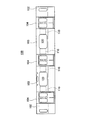
図2は、第1実施形態の中間窓ブロックについて、その製造過程を示した図である。この中間窓ブロック20は、長さの等しい帯状のパネルを上下に三枚突き合わせて接合したものである。つまり、上段の幕板パネル21および下段の腰板パネル23にはDLT鋼板が使用され、中段の吹寄パネル22にはHT鋼板が使用される。その幕板パネル21、吹寄パネル22および腰板パネル23が、パネルの端面同士を図示するように突合せ、その端面同士が重なった接合線28に沿ってレーザ溶接が行われる。幕板パネル21、吹寄パネル22および腰板パネル23による外板が形成される。
FIG. 2 is a diagram illustrating a manufacturing process of the intermediate window block according to the first embodiment. The
吹寄パネル22は、この中間窓ブロック20に形成する窓開口部の高さ寸法よりも幅(図面上下方向の寸法)が大きい板材である。従って、幕板パネル21、吹寄パネル22および腰板パネル23が接合された後に、破線で示す窓開口線25に沿って吹寄パネル22が切り抜かれ、中央部分に窓開口部が形成される。そのため、この中間窓ブロック20では、窓開口部の四隅に位置する窓隅部RがHT鋼板からなる吹寄パネル22によって構成されるので、補強プレートを設けなくても強度を確保することができる。よって、部品点数を減らすとともに、工数を減らすことにより作業を簡素化することができた。
The blowing
次に、図3は、第2実施形態の中間窓ブロックについて、その製造過程を示した図である。この中間窓ブロック30は、形状が凸形の幕板パネル31および腰板パネル33と、その間にあって左右の凹んだ位置に配置される四角形の吹寄パネル32によって構成される。ここでも幕板パネル31および腰板パネル33にはDLT鋼板が使用され、吹寄パネル32にはHT鋼板が使用される。そうした幕板パネル31、吹寄パネル32および腰板パネル33が、パネルの端面同士が図示するように突合せられ、その端面同士が重なった接合線38に沿ってレーザ溶接が行われる。
Next, FIG. 3 is a diagram showing a manufacturing process of the intermediate window block of the second embodiment. The
幕板パネル31、吹寄パネル32および腰板パネル33による外板が形成され、中央には窓開口部になる開口部35があいている。左右の吹寄パネル32は、この開口部35を左右に拡張するように、破線で示す窓開口線36に沿って切り取られ、中間窓ブロック30の窓開口部が形成される。従って、この中間窓ブロック30でも、窓開口部の四隅に位置する窓隅部RがHT鋼板からなる吹寄パネル32によって構成されているため、補強プレートを設けなくても強度を確保することができる。よって、部品点数を減らすとともに、工数を減らすことにより作業を簡素化することができた。
An outer panel is formed by the
以上、本発明に係る鉄道車両用構体の実施形態について説明したが、本発明はこれに限定されることなく、その趣旨を逸脱しない範囲で様々な変更が可能である。
前記実施形態では、図4に示す中間窓ブロック103に相当する構成のみを示して説明したが、図4に示す窓ブロック102に相当するものであってもよい。
As mentioned above, although embodiment of the structure for railcars concerning this invention was described, this invention is not limited to this, A various change is possible in the range which does not deviate from the meaning .
In the previous SL embodiment has been shown and described only the configuration corresponding to the
20 中間窓ブロック
21 幕板パネル
22 吹寄パネル
23 腰板パネル
25 窓開口線
R 窓隅部
20
Claims (2)
前記側構体を構成する窓ブロックは、幕板パネル、吹寄パネルおよび腰板パネルを含み、前記吹寄パネルは、当該窓ブロックに形成される窓開口部の窓隅部を含むものであり、前記幕板パネルおよび腰板パネルよりも高強度の板材であり、前記幕板パネルおよび腰板パネルは凸形状の板材であり、前記吹寄パネルは四角形状の板材であり、前記幕板パネルおよび腰板パネルの左右の凹んだ部分に前記吹寄パネルを配置する配置工程と、
前記幕板パネル、吹寄パネルおよび腰板パネルの端面同士を突き合わせた接合部をレーザ溶接する接合工程と、
接合後に前記吹寄パネルの一部のみが切り取られることにより前記窓開口部を形成する切り取り工程と、
を有することを特徴とする鉄道車両用構体の製造方法。 In the method for manufacturing a railway vehicle structure, the side structure, the roof structure, the wife structure and the underframe are joined, and the side structure is configured by joining a plurality of blocks divided in the vehicle body longitudinal direction.
The window block constituting the side structure includes a curtain panel, a blowing panel, and a waist panel , and the blowing panel includes a window corner of a window opening formed in the window block, plate der high strength than curtain panels and wainscot panels is, the curtain panels and wainscot panels are plates of convex, the吹寄panel is rectangular plate, said curtain panels and wainscot panel An arrangement step of arranging the blowing panel in the left and right recessed portions of
A joining step of laser welding a joint portion where the end faces of the curtain panel, blowing panel and waistboard panel are butted together;
A cutting step of forming the window opening by cutting only a part of the blowing panel after joining ;
The manufacturing method of the structure for rail vehicles characterized by having .
前記吹寄パネルは、前記幕板パネルおよび腰板パネルと同じ材料の板材であって板厚が前記幕板パネルおよび腰板パネルよりも厚いものであること、又は前記幕板パネルおよび腰板パネルと同じ板厚であって前記幕板パネルおよび腰板パネルよりも高強度の材料の板材であることを特徴とする鉄道車両用構体の製造方法。 In the manufacturing method of the structure for rail vehicles described in claim 1,
The blowing panel is a plate material made of the same material as the curtain plate panel and the waist plate panel, and has a plate thickness larger than that of the curtain plate panel and the waist plate panel, or the same plate as the curtain plate panel and the waist plate panel. A manufacturing method of a structure for a railway vehicle, characterized in that it is a thick plate material that is stronger than the curtain panel panel and the waist panel panel .
Priority Applications (1)
| Application Number | Priority Date | Filing Date | Title |
|---|---|---|---|
| JP2011145641A JP5871361B2 (en) | 2011-06-30 | 2011-06-30 | Method for manufacturing a railway vehicle structure |
Applications Claiming Priority (1)
| Application Number | Priority Date | Filing Date | Title |
|---|---|---|---|
| JP2011145641A JP5871361B2 (en) | 2011-06-30 | 2011-06-30 | Method for manufacturing a railway vehicle structure |
Publications (3)
| Publication Number | Publication Date |
|---|---|
| JP2013010468A JP2013010468A (en) | 2013-01-17 |
| JP2013010468A5 JP2013010468A5 (en) | 2014-08-07 |
| JP5871361B2 true JP5871361B2 (en) | 2016-03-01 |
Family
ID=47684753
Family Applications (1)
| Application Number | Title | Priority Date | Filing Date |
|---|---|---|---|
| JP2011145641A Expired - Fee Related JP5871361B2 (en) | 2011-06-30 | 2011-06-30 | Method for manufacturing a railway vehicle structure |
Country Status (1)
| Country | Link |
|---|---|
| JP (1) | JP5871361B2 (en) |
Families Citing this family (1)
| Publication number | Priority date | Publication date | Assignee | Title |
|---|---|---|---|---|
| JP6682240B2 (en) * | 2015-11-12 | 2020-04-15 | 日本車輌製造株式会社 | Block connection structure for railway vehicle and railway vehicle structure using the same |
Family Cites Families (5)
| Publication number | Priority date | Publication date | Assignee | Title |
|---|---|---|---|---|
| JP3189720B2 (en) * | 1997-01-08 | 2001-07-16 | 株式会社日立製作所 | Vehicle structure |
| JP4234341B2 (en) * | 2001-12-26 | 2009-03-04 | 日本車輌製造株式会社 | Manufacturing method of railway vehicle structure |
| JP2005161918A (en) * | 2003-12-01 | 2005-06-23 | Hitachi Ltd | Railcar body |
| JP2007125573A (en) * | 2005-11-02 | 2007-05-24 | Nippon Sharyo Seizo Kaisha Ltd | Workpiece joining method, joined body, and railroad vehicle |
| JP4516992B2 (en) * | 2008-07-02 | 2010-08-04 | 日本車輌製造株式会社 | Railway vehicle |
-
2011
- 2011-06-30 JP JP2011145641A patent/JP5871361B2/en not_active Expired - Fee Related
Also Published As
| Publication number | Publication date |
|---|---|
| JP2013010468A (en) | 2013-01-17 |
Similar Documents
| Publication | Publication Date | Title |
|---|---|---|
| JP2014108635A (en) | Railway vehicle | |
| JP2012206704A (en) | Connection flange structure | |
| JPH09221024A (en) | Manufacture of rolling stock structure | |
| JP2006341763A (en) | Truck frame for railcar | |
| JP5871361B2 (en) | Method for manufacturing a railway vehicle structure | |
| JP6788403B2 (en) | Bonding structure and method of connecting the side structure and the underframe | |
| JP6592404B2 (en) | Railway vehicle structure | |
| JP2005239029A (en) | Railway vehicle structural body | |
| JP6374358B2 (en) | Railway vehicle structure and manufacturing method thereof | |
| JP2011162086A (en) | Structure body made of metal and its manufacturing method | |
| JP5544227B2 (en) | Railway vehicle structure | |
| JP6923422B2 (en) | Body structure | |
| JP6230981B2 (en) | Rail vehicle structure | |
| JP4578985B2 (en) | Extruded hollow profile and railway vehicle structure formed by the profile | |
| JP4234696B2 (en) | Railcar head structure | |
| JP4227939B2 (en) | Railway vehicle structure and manufacturing method thereof | |
| JP5567359B2 (en) | Railway vehicle structure and manufacturing method thereof | |
| JP6909019B2 (en) | Railroad vehicle structure | |
| JP2006008078A (en) | Railway vehicle body and its manufacturing method | |
| JP7178220B2 (en) | railroad vehicle structure | |
| JP5871586B2 (en) | CONNECTED BODY, VEHICLE COMPRISING BODY AND MANUFACTURING METHOD | |
| EP1524064B1 (en) | Structural body of railway car and joint structure for friction stir welding | |
| JP5941837B2 (en) | RAILWAY VEHICLE BODY, MANUFACTURING METHOD FOR RAILWAY VEHICLE BODY | |
| JP2024015702A (en) | Railway vehicle and its manufacturing method | |
| JP6430766B2 (en) | Railway vehicle structure |
Legal Events
| Date | Code | Title | Description |
|---|---|---|---|
| A521 | Written amendment |
Free format text: JAPANESE INTERMEDIATE CODE: A523 Effective date: 20140624 |
|
| A621 | Written request for application examination |
Free format text: JAPANESE INTERMEDIATE CODE: A621 Effective date: 20140624 |
|
| A977 | Report on retrieval |
Free format text: JAPANESE INTERMEDIATE CODE: A971007 Effective date: 20150520 |
|
| A131 | Notification of reasons for refusal |
Free format text: JAPANESE INTERMEDIATE CODE: A131 Effective date: 20150602 |
|
| A521 | Written amendment |
Free format text: JAPANESE INTERMEDIATE CODE: A523 Effective date: 20150715 |
|
| A131 | Notification of reasons for refusal |
Free format text: JAPANESE INTERMEDIATE CODE: A131 Effective date: 20151104 |
|
| A521 | Written amendment |
Free format text: JAPANESE INTERMEDIATE CODE: A523 Effective date: 20151210 |
|
| TRDD | Decision of grant or rejection written | ||
| A01 | Written decision to grant a patent or to grant a registration (utility model) |
Free format text: JAPANESE INTERMEDIATE CODE: A01 Effective date: 20160106 |
|
| A61 | First payment of annual fees (during grant procedure) |
Free format text: JAPANESE INTERMEDIATE CODE: A61 Effective date: 20160108 |
|
| R150 | Certificate of patent or registration of utility model |
Ref document number: 5871361 Country of ref document: JP Free format text: JAPANESE INTERMEDIATE CODE: R150 |
|
| LAPS | Cancellation because of no payment of annual fees |