JP5867694B2 - Game machine - Google Patents

Game machine Download PDF

Info

Publication number
JP5867694B2
JP5867694B2 JP2011228527A JP2011228527A JP5867694B2 JP 5867694 B2 JP5867694 B2 JP 5867694B2 JP 2011228527 A JP2011228527 A JP 2011228527A JP 2011228527 A JP2011228527 A JP 2011228527A JP 5867694 B2 JP5867694 B2 JP 5867694B2
Authority
JP
Japan
Prior art keywords
inner frame
front door
shaft
piece
main body
Prior art date
Legal status (The legal status is an assumption and is not a legal conclusion. Google has not performed a legal analysis and makes no representation as to the accuracy of the status listed.)
Active
Application number
JP2011228527A
Other languages
Japanese (ja)
Other versions
JP2013085678A (en
JP2013085678A5 (en
Inventor
良和 本庄
良和 本庄
Current Assignee (The listed assignees may be inaccurate. Google has not performed a legal analysis and makes no representation or warranty as to the accuracy of the list.)
Sanyo Bussan Co Ltd
Original Assignee
Sanyo Bussan Co Ltd
Priority date (The priority date is an assumption and is not a legal conclusion. Google has not performed a legal analysis and makes no representation as to the accuracy of the date listed.)
Filing date
Publication date
Application filed by Sanyo Bussan Co Ltd filed Critical Sanyo Bussan Co Ltd
Priority to JP2011228527A priority Critical patent/JP5867694B2/en
Publication of JP2013085678A publication Critical patent/JP2013085678A/en
Publication of JP2013085678A5 publication Critical patent/JP2013085678A5/ja
Application granted granted Critical
Publication of JP5867694B2 publication Critical patent/JP5867694B2/en
Active legal-status Critical Current
Anticipated expiration legal-status Critical

Links

Images

Description

本発明は、パチンコ機に代表される遊技機に関するものである。   The present invention relates to a gaming machine represented by a pachinko machine.

パチンコ機などの遊技機は、発射された遊技球が案内されて流下する遊技領域が前面に形成された遊技盤と、この遊技盤の盤面を前方からガラス等を通して視認可能な状態で覆う前面枠等の部材とを備えるものが一般的である。上記前面枠等の部材は、通常、一方側縁で軸支されて開き戸式に開閉可能に取り付けられており、例えば、遊技盤の盤面に植設された釘を調整したり、遊技領域を流下する途上でいずれかの部位に引っ掛かった遊技球を取り除いたり、遊技球の通過により汚れた盤面を清掃したりといった各種の作業の際には、この前面枠等の部材を開放して前方から作業できるようになっている(以下、この前面枠等のように、遊技盤を前方から覆う開閉可能な部材を総称して「前面扉」とも称す)。   A game machine such as a pachinko machine has a game board in which a game area in which a launched game ball is guided and flows down is formed on the front surface, and a front frame that covers the board surface of the game board from the front in a state that is visible through glass or the like. The thing provided with members, such as, is common. The members such as the front frame are usually pivotally supported at one side edge and attached so as to be openable and closable, for example, by adjusting nails planted on the board surface of the game board or flowing down the game area. When performing various tasks such as removing game balls caught on any part of the course or cleaning the board surface that has become dirty due to the passage of game balls, work from the front by opening the front frame and other members. (Hereinafter, members that can be opened and closed to cover the game board from the front, such as the front frame or the like, are collectively referred to as “front door”).

特開2004−8331号公報JP 2004-8331 A

遊技機の寸法は規格化されていて一定となっているが、遊技領域に配置される液晶装置が大型化してきていること等から、釘が植設される領域が、周辺に拡がってきていて、前面扉が軸支された側縁部の位置にまでも及ぶようになっている。このため、上述のような盤面に対する各種作業を行うために前面扉を開放した際に、この前面扉が軸支された側縁部の付近では該前面扉が邪魔になって盤面に対する作業がしづらくなっているという問題がある。   The dimensions of gaming machines are standardized and constant, but the area where nails are implanted has expanded to the periphery due to the increasing size of liquid crystal devices arranged in the gaming area. The front door extends to the position of the side edge portion on which the front door is pivotally supported. For this reason, when the front door is opened to perform various operations on the panel surface as described above, the front door becomes an obstacle in the vicinity of the side edge portion where the front door is pivotally supported. There is a problem that it is difficult.

また、前面扉には本来的に、これを開放すると開放した側に隣接する遊技機の遊技者に邪魔となりやすいという問題もある。
換言すれば、開放した前面扉は、盤面に対する作業だけでなく隣接する遊技機の遊技に対しても、即ち遊技機の内外で邪魔となりやすい。
In addition, there is a problem that the front door is inherently obstructive to the player of the gaming machine adjacent to the opened side when it is opened.
In other words, the opened front door is likely to be a hindrance not only for work on the board surface but also for games of adjacent gaming machines, that is, inside and outside the gaming machine.

本発明は、かかる問題点に鑑みて案出されたものであり、開放した前面扉が盤面に対する作業にも隣接する遊技機の遊技にも邪魔となり難い遊技機を提供することを目的とする。   The present invention has been devised in view of such problems, and it is an object of the present invention to provide a gaming machine in which an open front door is unlikely to obstruct work on a board surface or a game of an adjacent gaming machine.

本発明にかかる遊技機は、上記目的を達成するために、
本体部材(遊技球が流下する遊技領域が前面に形成された遊技盤)と、本体部材の前面(この遊技盤の盤面)側を覆う前面扉と、この前面扉を開放操作するための鍵操作機構とを備える遊技機であって、
前記前面扉が、対向する一対の端縁部でそれぞれ軸支機構により遊技機本体側の部材に着脱可能に軸支され、
前記鍵操作機構を操作することにより、前記一対の軸支機構における軸支状態のうちのいずれか一方を軸として開閉可能に構成されており、
前記鍵操作機構が、鍵を挿入して一方に回転させると、この鍵の一方の回転による動力が伝達機構を介して伝達されることにより、前記一対の軸支機構における軸支状態のうちのいずれか一方を解除することができ、鍵を挿入して他方に回転させると、この鍵の他方の回転による動力が伝達機構を介して伝達されることにより、前記一対の軸支機構における軸支状態のうちの他方を解除することができるように構成され、
前記前面扉が軸支される遊技機本体側の部材が内枠となっており、さらに該内枠が、遊技機本体側の別の部材に軸支されるとともに内枠係合部により該別の部材に係合して閉じた状態に拘束され得るようになっており、前記鍵操作機構が、鍵を挿入して押し込みながら回転させると、この鍵の回転による動力が前記内枠係合部に伝達されることにより、前記遊技機本体側の別の部材に対して前記内枠が閉じて拘束された状態が解除されるように構成されていることを特徴とする。
In order to achieve the above object, the gaming machine according to the present invention
A main body member (game board on which a game area where a game ball flows down is formed on the front surface), a front door that covers the front surface of the main body member (the board surface of this game board), and a key operation for opening the front door A gaming machine comprising a mechanism,
The front door is pivotally supported by a pivotal support mechanism at a pair of opposing edge portions so as to be detachable from a member on the gaming machine main body side,
By operating the key operation mechanism, it is configured to be openable and closable with any one of the shaft support states in the pair of shaft support mechanisms as an axis ,
When the key operation mechanism inserts the key and rotates it to one side, the power generated by the rotation of one of the keys is transmitted through the transmission mechanism. Either one can be released, and when the key is inserted and rotated to the other, the power generated by the rotation of the other of the key is transmitted through the transmission mechanism. Configured to be able to release the other of the states,
A member on the gaming machine main body side on which the front door is pivotally supported is an inner frame, and the inner frame is pivotally supported by another member on the gaming machine main body side and is separated by an inner frame engaging portion. When the key operating mechanism is rotated while inserting and pushing in the key, the power generated by the rotation of the key is applied to the inner frame engaging portion. By being transmitted to the game machine, the state in which the inner frame is closed and restrained with respect to another member on the gaming machine main body side is released .

上記本発明の構成によれば、前面扉を一対の端縁部でそれぞれ軸支機構により遊技機本体側の部材に軸支することによって、前面扉を閉じた状態(閉状態)で拘束することができる。一方、この閉状態で鍵操作機構を操作(開放操作)して一対の軸支機構における軸支状態のうちのいずれか一方を軸として開閉することによって、前面扉を回動させて開き戸式に開放することができる。即ち、前面扉における一対の端縁部のうち、いずれの端縁部を固定端(軸支側端)としいずれの端縁部を自由端とするかを自在に選択して切替えることができるので、前面扉をその一対の端縁部のうちのいずれの端縁部側へも自在に選択的に開放することができる。   According to the above configuration of the present invention, the front door is restrained in a closed state (closed state) by pivotally supporting the front door on a member on the gaming machine main body side with a pair of end edges by a shaft support mechanism. Can do. On the other hand, by operating (opening operation) the key operation mechanism in this closed state, the front door is rotated to open and close with one of the shaft support states of the pair of shaft support mechanisms as an axis, so that the front door is turned Can be opened. In other words, among the pair of edge portions in the front door, it is possible to freely select which edge portion is a fixed end (shaft support side end) and which end edge portion is a free end, and can be switched. The front door can be selectively opened freely to any one of the pair of end edges.

したがって、盤面に対する各種作業を行う際には、作業を行う部位から比較的に離れた端縁部側へ前面扉を開放することにより、該前面扉が作業の邪魔とならないようにすることができる。   Therefore, when performing various operations on the board surface, the front door can be prevented from interfering with the operation by opening the front door to the edge portion side relatively away from the site where the operation is performed. .

また、両隣の遊技機のうち、例えば遊技中でない等の理由により比較的に邪魔になり難くなっている一方側へ選択的に前面扉を開放することにより、該前面扉が他方側に隣接する遊技機の遊技に対して邪魔とならないようにすることもできる。   Further, among the adjacent gaming machines, the front door is adjacent to the other side by selectively opening the front door to one side that is relatively difficult to get in the way, for example, because it is not playing. It is also possible not to get in the way of gaming machines.

本発明によれば、開放した前面扉が盤面に対する作業にも隣接する遊技機の遊技にも邪魔となり難いようにすることができる。   According to the present invention, it is possible to prevent the opened front door from interfering with work on the board surface and games of adjacent gaming machines.

パチンコ機の一例を示す正面図。The front view which shows an example of a pachinko machine. パチンコ機の一例を示す正面側の斜視図。The perspective view of the front side which shows an example of a pachinko machine. 遊技盤の一例を示す正面図。The front view which shows an example of a game board. 図3の遊技盤の斜視図。The perspective view of the game board of FIG. パチンコ機の一例を示す背面図。The rear view which shows an example of a pachinko machine. パチンコ機の電気的構成の一例を示すブロック図。The block diagram which shows an example of the electrical constitution of a pachinko machine. 遊技機本体側の部材(内枠)および前面扉がいずれも閉状態にある状況を示す、左前側から視た斜視図。The perspective view seen from the front left side which shows the condition in which the member (inner frame) and front door of a game machine main body side are both closed. 遊技機本体側の部材(内枠)および前面扉がいずれも閉状態にある状況を示す、右前側から視た斜視図。The perspective view seen from the front right side which shows the condition in which the member (inner frame) and front door of a game machine main body side are both closed. 遊技機本体側の部材(内枠)および前面扉がいずれも閉状態にある状況を示す、左後側から視た斜視図。The perspective view seen from the left rear side which shows the condition in which the member (inner frame) and front door of a game machine main body side are both closed. 遊技機本体側の部材(内枠)および前面扉がいずれも閉状態にある状況を示す、右後側から視た斜視図。The perspective view seen from the right rear side which shows the condition in which the member (inner frame) and front door of a game machine main body side are both closed. 遊技機本体側の部材(内枠)および前面扉がいずれも閉状態にある状況を示す背面図。The rear view which shows the condition in which the game machine main body side member (inner frame) and front door are both closed. 図11の四隅部の状況を示す部分拡大図。The elements on larger scale which show the condition of the four corners of FIG. 図9の四隅部の状況を示す部分拡大図。The elements on larger scale which show the condition of the four corners of FIG. 遊技機本体側の部材(内枠)の閉状態が解除された状況を示す、左前側から視た斜視図。The perspective view seen from the left front side which shows the condition by which the closed state of the member (inner frame) by the side of a game machine main body was cancelled | released. 遊技機本体側の部材(内枠)の閉状態が解除された状況を示す、右前側から視た斜視図。The perspective view seen from the front right side which shows the condition by which the closed state of the member (inner frame) by the side of a game machine main body was cancelled | released. 遊技機本体側の部材(内枠)の閉状態が解除された状況況を示す、左後側から視た斜視図。The perspective view seen from the left rear side which shows the condition condition where the closed state of the member (inner frame) by the side of a game machine main body was cancelled | released. 遊技機本体側の部材(内枠)の閉状態が解除された状況を示す、右後側から視た斜視図。The perspective view seen from the right rear side which shows the condition where the closed state of the member (inner frame) by the side of a game machine main body was cancelled | released. 遊技機本体側の部材(内枠)の閉状態が解除された状況を示す背面図。The rear view which shows the condition where the closed state of the member (inner frame) by the side of a game machine main body was cancelled | released. 図18の四隅部の状況を示す部分拡大図。The elements on larger scale which show the condition of the four corners of FIG. 図16の四隅部の状況を示す部分拡大図。The elements on larger scale which show the condition of the four corners of FIG. 前面扉を左開きとした状況を示す、左前側から視た斜視図。The perspective view seen from the left front side which shows the condition which made the front door left open. 前面扉を左開きとした状況を示す、右前側から視た斜視図。The perspective view seen from the front right side which shows the condition which made the front door left open. 前面扉を左開きとした状況を示す、左後側から視た斜視図。The perspective view seen from the left rear side which shows the condition which made the front door left open. 前面扉を左開きとした状況を示す、右後側から視た斜視図。The perspective view seen from the right rear side which shows the condition which made the front door left open. 前面扉を左開きとした状況を示す背面図。The rear view which shows the condition which made the front door left open. 図25の四隅部の状況を示す部分拡大図。The elements on larger scale which show the condition of the four corners of FIG. 図23の四隅部の状況を示す部分拡大図。The elements on larger scale which show the condition of the four corners of FIG. 前面扉を右開きとした状況を示す、左前側から視た斜視図。The perspective view seen from the left front side which shows the condition which made the front door opened right. 前面扉を右開きとした状況を示す、右前側から視た斜視図。The perspective view seen from the front right side which shows the condition which made the front door opened right. 前面扉を右開きとした状況を示す、左後側から視た斜視図。The perspective view seen from the left rear side which shows the condition which made the front door opened right. 前面扉を右開きとした状況を示す、右後側から視た斜視図。The perspective view seen from the right rear side which shows the condition which made the front door opened right. 前面扉を右開きとした状況を示す背面図。The rear view which shows the condition which made the front door opened right. 図32の四隅部の状況を示す部分拡大図。The elements on larger scale which show the condition of the four corners of FIG. 図30の四隅部の状況を示す部分拡大図。The elements on larger scale which show the condition of the four corners of FIG. 遊技機本体側の部材(内枠)を開放操作するときの鍵操作機構の状況を示す部分左側面図。The partial left view which shows the condition of the key operation mechanism when operating the member (inner frame) by the side of a game machine main body. 遊技機本体側の部材(内枠)を開放操作するときの鍵操作機構の状況を示す、左後側から視た部分斜視図。The partial perspective view seen from the left rear side which shows the condition of the key operation mechanism when opening a member (inner frame) on the gaming machine main body side. 前面扉を開放操作するときの鍵操作機構の状況を示す部分左側面図。The partial left view which shows the condition of the key operation mechanism when opening a front door. 前面扉を開放操作するときの鍵操作機構の状況を示す、左後側から視た部分斜視図。The partial perspective view seen from the left rear side which shows the condition of the key operation mechanism when opening operation of a front door. 鍵操作機構およびその周辺を示す、前側から視た分解斜視図。The disassembled perspective view which looked at the key operation mechanism and its periphery from the front side. 鍵操作機構およびその周辺を示す、後側から視た分解斜視図。The disassembled perspective view seen from the rear side which shows a key operation mechanism and its periphery. 軸支状態にあるときの軸支機構の可動部材、基材および回転軸を示す分解斜視図。The disassembled perspective view which shows the movable member, base material, and rotating shaft of a shaft support mechanism in a shaft support state. 軸支状態にあるときの右上軸支部において基材を取り外した状況を示す一部分解斜視図。The partial exploded perspective view which shows the condition which removed the base material in the upper right shaft support part when it exists in a shaft support state. 軸支状態を解除したときの軸支機構の可動部材、基材および回転軸を示す分解斜視図。The disassembled perspective view which shows the movable member, base material, and rotating shaft of a shaft support mechanism when the shaft support state is released. 軸支状態を解除したときの右上軸支部において基材を取り外した状況を示す一部分解斜視図。The partial exploded perspective view which shows the condition which removed the base material in the upper right shaft support part when the shaft support state was cancelled | released. 軸支状態を解除して前面扉を開放したときの右上軸支部の状況を示す斜視図。The perspective view which shows the condition of an upper right axis support part when canceling | releasing a pivot state and opening a front door. 右上軸支部の前側から視た分解斜視図。The exploded perspective view seen from the front side of an upper right axis support part. 右上軸支部の後側から視た分解斜視図。The exploded perspective view seen from the back side of an upper right axis support part. 右上軸支部の軸受側機構およびその遊技機本体側の部材(内枠)への取付状況を示す、前側から視た斜視図。The perspective view seen from the front side which shows the attachment condition to the bearing side mechanism of the upper right shaft support part, and the member (inner frame) of the game machine main body side. 右上軸支部の軸受側機構およびその遊技機本体側の部材(内枠)への取付状況を示す、後側から視た斜視図。The perspective view seen from the rear side which shows the attachment condition to the bearing side mechanism of the upper right shaft support part, and the member (inner frame) of the game machine main body side. 前面扉を右開きとしたときの案内部材およびその取付状況を示す斜視図。The perspective view which shows the guide member when the front door is made into right opening, and its attachment condition. 前面扉を左開きとしたときの案内部材およびその取付状況を示す斜視図。The perspective view which shows the guide member when the front door is made into left opening, and its attachment condition. 案内部材に配線を取り付ける状況を示す分解部分断面斜視図。The disassembled partial cross-section perspective view showing a situation where wiring is attached to the guide member. 軸支機構の他の例を示す平面図。The top view which shows the other example of a shaft support mechanism. 軸支機構の他の例およびその操作状況を示す平面図。The top view which shows the other example of the shaft support mechanism, and its operation condition. 図53の回転軸の要部を示す部分斜視図。The fragmentary perspective view which shows the principal part of the rotating shaft of FIG. 遊技機本体側の部材(内枠)と前面扉との電気的接続構造の他の例を示す部分断面斜視図。The fragmentary sectional perspective view which shows the other example of the electrical connection structure of the member (inner frame) and front door of the game machine main body side. 他の例に係る前面扉の取付構造およびその開閉状況を示す平面図。The top view which shows the attachment structure of the front door which concerns on another example, and its opening-and-closing situation.

以下、本発明の最良の形態を、図面に基づいて詳細に説明する。ここでは、遊技機としてパチンコ遊技機(以下、単に「パチンコ機」という)を挙げる。   Hereinafter, the best mode of the present invention will be described in detail with reference to the drawings. Here, pachinko gaming machines (hereinafter simply referred to as “pachinko machines”) are listed as gaming machines.

(パチンコ機正面側の構成)
図1はパチンコ機10の正面図であり、図2はパチンコ機10の斜視図である。図1、2に示すように、パチンコ機10は、当該パチンコ機10の外殻を形成する外枠11と、この外枠11の一側部に開閉可能に支持された内枠12とを備えている。以下に、外枠11と内枠12との構成を個別に説明する。
(Configuration of front side of pachinko machine)
FIG. 1 is a front view of the pachinko machine 10, and FIG. 2 is a perspective view of the pachinko machine 10. As shown in FIGS. 1 and 2, the pachinko machine 10 includes an outer frame 11 that forms an outer shell of the pachinko machine 10, and an inner frame 12 that is supported on one side of the outer frame 11 so as to be opened and closed. ing. Below, the structure of the outer frame 11 and the inner frame 12 is demonstrated separately.

上記外枠11は、木製の板材により全体として矩形状に構成され、小ネジ等の離脱可能な締結具により各板材が組み付けられている。なお、外枠11は樹脂やアルミニウム等の軽金属により構成されていてもよい。このように構成することにより、パチンコ機の軽量化を図ることができるからである。   The outer frame 11 is formed in a rectangular shape as a whole by a wooden plate material, and each plate material is assembled by a detachable fastener such as a small screw. The outer frame 11 may be made of a light metal such as resin or aluminum. This is because such a configuration can reduce the weight of the pachinko machine.

一方、上記内枠12の開閉軸線はパチンコ機10の正面からみてハンドル(後述する遊技球発射ハンドル18)設置箇所の反対側(図1のパチンコ機10の左側)で上下に延びるように設定されており、この開閉軸線を軸心にして内枠12が前方側に十分に開放できるようになっている。このような構成とするのは、内枠12の開閉軸線がハンドル設置箇所側(図1のパチンコ機10の右側)で上下方向にあるとすると、内枠12を開放する際に遊技球発射ハンドル18の頭部等が隣なりのパチンコ機やカードユニット(球貸しユニット)に干渉することになり、内枠12を十分に開放できないからである。また、内枠12は合成樹脂、具体的にはABS(アクリロニトリル−ブタジエン−スチレン)樹脂から成る。こうすることで、粘性が高く衝撃に強くでき、低コストで製造できるという利点が発揮される。   On the other hand, the opening / closing axis of the inner frame 12 is set so as to extend vertically on the opposite side (left side of the pachinko machine 10 in FIG. 1) from the position where the handle (game ball launching handle 18 described later) is installed as viewed from the front of the pachinko machine 10. The inner frame 12 can be sufficiently opened to the front side with the opening / closing axis as the axis. If the opening / closing axis of the inner frame 12 is in the vertical direction on the handle installation location side (the right side of the pachinko machine 10 in FIG. 1), the game ball launching handle is opened when the inner frame 12 is opened. This is because the 18 heads and the like interfere with adjacent pachinko machines and card units (ball lending units), and the inner frame 12 cannot be fully opened. The inner frame 12 is made of a synthetic resin, specifically, ABS (acrylonitrile-butadiene-styrene) resin. By doing so, the advantages of high viscosity and high impact resistance and low cost production are exhibited.

また、内枠12は、大別すると、その最下部に取り付けられた下皿ユニット13と、この下皿ユニット13よりも上側の範囲で後述するように内枠12の左側および右側の上下方向の開閉軸線を軸心にして開閉自在に取り付けられた前面枠セット14と、図示しない樹脂ベースと、この樹脂ベースの後側に取り付けられる後述の遊技盤30とを備えている。これらの各構成を以下に詳細に説明する。   The inner frame 12 can be broadly divided into a lower tray unit 13 attached to the lowermost portion thereof, and a vertical direction on the left and right sides of the inner frame 12 as will be described later in a range above the lower tray unit 13. A front frame set 14 that is attached to be openable and closable with an opening / closing axis as an axis, a resin base (not shown), and a game board 30 (described later) attached to the rear side of the resin base are provided. Each of these configurations will be described in detail below.

上記下皿ユニット13は、内枠12に対してネジ等の締結具により固定されている。この下皿ユニット13の前面側には、下皿15と球抜きレバー17と遊技球発射ハンドル18と灰皿22と音出力口24が設けられている。球受皿としての下皿15は、下皿ユニット13のほぼ中央部に設けられており、後述の上皿が満タンになった場合等に排出口16より排出される遊技球を停留する役割がある。上記球抜きレバー17は、下皿15内の遊技球を抜くためのものであり、この球抜きレバー17を図1で左側に移動させることにより、下皿15の底面の所定箇所が開口され、下皿15内に停留された遊技球を下皿15の底面の開口部分を通して遊技者の持球貯留箱(ドル箱)に排出することができる。上記遊技球発射ハンドル18は、下皿15よりも右方で手前側に突出するように配設されている。遊技者による遊技球発射ハンドル18の操作に応じて、発射ソレノイドを備えた遊技球発射装置によって遊技球が後述する遊技盤30の方へ打ち込まれるようになっている。上記音出力口24は、下皿ユニット13内あるいは背面に設けられたスピーカからの音を出力するための出力口である。また、灰皿22は下皿15の左方に設けられている。灰皿22は左右方向(水平方向)の軸線を軸心にして回動(例えば前方側に向けて前回り)するように、その右側が下皿15に片待ち支持されている。   The lower plate unit 13 is fixed to the inner frame 12 with a fastener such as a screw. On the front side of the lower tray unit 13, a lower tray 15, a ball release lever 17, a game ball launching handle 18, an ashtray 22, and a sound output port 24 are provided. The lower tray 15 serving as a ball receiving tray is provided at substantially the center of the lower tray unit 13 and plays a role of stopping a game ball discharged from the discharge port 16 when the upper tray described later becomes full. is there. The ball removal lever 17 is for removing a game ball in the lower tray 15, and by moving the ball removal lever 17 to the left in FIG. 1, a predetermined location on the bottom surface of the lower tray 15 is opened. The game ball stopped in the lower plate 15 can be discharged to the player's ball storage box (dollar box) through the opening on the bottom surface of the lower plate 15. The game ball launching handle 18 is disposed so as to protrude to the front side on the right side of the lower plate 15. In accordance with the operation of the game ball launching handle 18 by the player, the game ball is driven toward a game board 30 described later by a game ball launching device having a launch solenoid. The sound output port 24 is an output port for outputting sound from a speaker provided in the lower plate unit 13 or on the back surface. The ashtray 22 is provided on the left side of the lower plate 15. The right side of the ashtray 22 is supported by the lower plate 15 so as to rotate about the axis in the left-right direction (horizontal direction) as an axis (for example, forwardly toward the front side).

なお、下皿ユニット13はその大部分が内枠12と同様、ABS樹脂にて成形されている。   Note that most of the lower dish unit 13 is molded of ABS resin in the same manner as the inner frame 12.

一方、前面枠セット14の下部(上述の下皿15の上方位置)には、遊技球の受皿としての上皿19が前面枠セット14と一体的に設けられている。この上皿19は、遊技球を一旦貯留し、一列に整列させながら遊技球発射装置38の方へ導出するための球受皿である。従来のパチンコ機では前面枠セットの下方に内枠に対し開閉可能な前飾り枠が設けられ、該前飾り枠に上皿が設けられていたのであるが、本形態では前飾り枠が省略され、前面枠セット14に対し直接的に上皿19が設けられている。この上皿19も下皿15と同様、表面層が難燃性のABS樹脂にて成形される構成となっている。また、上皿19の左下方には、装飾図柄表示装置42の背景を変える等の操作を遊技者が行なうための演出ボタン79が設けられている。   On the other hand, an upper plate 19 as a receiving tray for game balls is provided integrally with the front frame set 14 at a lower portion of the front frame set 14 (above the lower plate 15 described above). The upper tray 19 is a ball receiving tray for temporarily storing the game balls and guiding them to the game ball launching device 38 while aligning them in a line. In the conventional pachinko machine, a front decorative frame that can be opened and closed with respect to the inner frame is provided below the front frame set, and an upper plate is provided on the front decorative frame. However, in this embodiment, the front decorative frame is omitted. The upper plate 19 is provided directly on the front frame set 14. Similar to the lower plate 15, the upper plate 19 has a structure in which the surface layer is formed of flame-retardant ABS resin. In addition, an effect button 79 for the player to perform an operation such as changing the background of the decorative symbol display device 42 is provided at the lower left of the upper plate 19.

加えて、前面枠セット14にはその周囲(例えばコーナー部分)に各種ランプ等の発光手段が設けられている。これら発光手段は、大当たり遊技状態時等における遊技状態の変化に応じて点灯、点滅のように発光態様が変更制御され遊技中の演出効果を高める役割を果たすものである。例えば、窓部101の周縁には、LED等の発光手段を内蔵した環状電飾部102が左右対称に設けられ、大当たり遊技状態時に点灯や点滅を行うことにより、大当たり遊技状態中であることを報知する構成である。   In addition, the front frame set 14 is provided with light emitting means such as various lamps around it (for example, a corner portion). These light emitting means play a role of enhancing the effect of the game during the game by changing and controlling the light emission mode such as lighting and blinking according to the change of the game state in the big hit game state or the like. For example, at the periphery of the window portion 101, an annular illumination portion 102 containing a light emitting means such as an LED is provided symmetrically, and lighting or blinking in the big hit gaming state, it is in a big hit gaming state It is the structure which alert | reports.

また、窓部101の下方には貸球操作部120が配設されており、貸球操作部120には球貸しボタン121と、返却ボタン122と、度数表示部123とが設けられている。パチンコ機10の側方に配置された図示しないカードユニット(球貸しユニット)に紙幣やカード等を投入した状態で貸球操作部120が操作されると、その操作に応じて遊技球の貸出が行われる。球貸しボタン121は、カード等(記録媒体)に記録された情報に基づいて貸出球を得るために操作されるものであり、カード等に残額が存在する限りにおいて貸出球が上皿19に供給される。返却ボタン122は、カードユニットに挿入されたカード等の返却を求める際に操作される。度数表示部123はカード等の残額情報を表示するものである。なお、カードユニットを介さずに球貸し装置部から上皿に遊技球が直接貸し出されるパチンコ機、いわゆる現金機では貸球操作部120が不要となる。故に、貸球操作部120の設置部分に、飾りシール等が付されるようになっている。これにより、カードユニットを用いたパチンコ機と現金機との貸球操作部の共通化が図れる。   In addition, a ball lending operation unit 120 is disposed below the window unit 101, and the ball lending operation unit 120 is provided with a ball lending button 121, a return button 122, and a frequency display unit 123. When the ball lending operation unit 120 is operated with a bill or a card inserted in a card unit (ball lending unit) (not shown) arranged on the side of the pachinko machine 10, a game ball is lent according to the operation. Done. The ball lending button 121 is operated to obtain a lending ball based on information recorded on a card or the like (recording medium), and the lending ball is supplied to the upper plate 19 as long as there is a remaining amount on the card or the like. Is done. The return button 122 is operated when requesting the return of a card or the like inserted into the card unit. The frequency display unit 123 displays remaining amount information such as a card. Note that the ball lending operation unit 120 is not required for a pachinko machine in which a game ball is directly rented from the ball lending device unit to the upper plate without using a card unit, that is, a so-called cash machine. Therefore, a decorative seal or the like is attached to the installation portion of the ball rental operation unit 120. Thereby, the common use of the lending operation unit of the pachinko machine using the card unit and the cash machine can be achieved.

次に、図3〜図4を用いて遊技盤30の構成を説明する。図3は遊技盤30の構成を示す正面図であり、図4は、収容部の入口61付近を模式的に示す図である。遊技盤30は、一般入賞口31、可変入賞装置32、上始動口33aと下始動口33b(作動チャッカ33bで構成)とから成る第1の始動口33、第2の始動口34(スルーゲートで構成)、特別図柄表示装置38、普通図柄表示装置41、装飾図柄表示装置42を備える可変表示装置ユニット35等が設けられている。これらの一般入賞口31、可変入賞装置32、第1の始動口33、第2の始動口34、可変表示装置ユニット35等は、遊技盤30における、ルータ加工によって形成された各貫通穴にそれぞれに配設され、遊技盤30前面側から木ネジ等により取り付けられている。また、下始動口33bの入口には、図4に示すように一対の開閉羽根60が設けられており、遊技球を案内する開放位置と、下始動口33b内に遊技球が入りにくくなる閉塞位置を採りうる。開閉羽根60は、遊技盤30の裏面側に配設されたソレノイドSL1によって駆動される。また、下始動口33bの下方には、収容部の入口61が配置されている。収容部の入口61については、後に言及する。収容部の入口61内には、入球検出スイッチSW1が設けられている。   Next, the configuration of the game board 30 will be described with reference to FIGS. FIG. 3 is a front view showing the configuration of the game board 30, and FIG. 4 is a diagram schematically showing the vicinity of the entrance 61 of the housing portion. The game board 30 includes a first start port 33 and a second start port 34 (through gate) each comprising a general winning port 31, a variable winning device 32, an upper starting port 33a and a lower starting port 33b (configured by an operation chuck 33b). A variable display device unit 35 including a special symbol display device 38, a normal symbol display device 41, a decorative symbol display device 42, and the like. The general winning port 31, the variable winning device 32, the first starting port 33, the second starting port 34, the variable display unit 35 and the like are respectively provided in the through holes formed by the router processing in the game board 30. The game board 30 is attached from the front side with a wood screw or the like. Further, as shown in FIG. 4, a pair of opening and closing blades 60 is provided at the entrance of the lower start port 33b, and an open position for guiding the game ball and a blockage that prevents the game ball from entering the lower start port 33b. Can take a position. The opening / closing blade 60 is driven by a solenoid SL1 disposed on the back side of the game board 30. In addition, an inlet 61 of the accommodating portion is disposed below the lower start port 33b. The inlet 61 of the housing portion will be described later. The entrance detection switch SW1 is provided in the entrance 61 of the housing portion.

前述の一般入賞口31、可変入賞装置32および第1の始動口33に遊技球が入球し、当該入球が後述する検出スイッチ(入賞口スイッチ、カウントスイッチ、作動口スイッチ等)で検出され、この検出スイッチの出力に基づいて、上皿19(または下皿15)へ所定数の賞品球が払い出される。その他に、遊技盤30にはアウト口36が設けられており、各種入賞装置等に入球しなかった遊技球はこのアウト口36を通って図示しない球排出路の方へと案内されるようになっている。遊技盤30には、遊技球の落下方向を適宜分散、調整等するために多数の釘が植設されているとともに、各種部材(役物)が配設されている。   A game ball enters the above-described general winning port 31, variable winning device 32, and first start port 33, and the received ball is detected by a detection switch (a winning port switch, a count switch, an operation port switch, etc.) described later. Based on the output of the detection switch, a predetermined number of prize balls are paid out to the upper plate 19 (or the lower plate 15). In addition, the game board 30 is provided with an out port 36, and game balls that have not entered the various winning devices etc. are guided through the out port 36 to a ball discharge path (not shown). It has become. A number of nails are implanted in the game board 30 in order to appropriately disperse and adjust the falling direction of the game balls, and various members (instruments) are arranged.

上記特別図柄表示装置38は、第1の始動口33への入賞をトリガとして識別情報としての特別図柄を変動表示し、上記装飾図柄表示装置42は特別図柄の変動表示に対応した装飾図柄を変動表示し、上記普通図柄表示装置41は第2の始動口34の通過をトリガとして普通図柄を変動表示する。   The special symbol display device 38 variably displays a special symbol as identification information with a winning at the first start port 33 as a trigger, and the decorative symbol display device 42 varies a decorative symbol corresponding to the variation display of the special symbol. The normal symbol display device 41 variably displays the normal symbol with the passage of the second start port 34 as a trigger.

上記特別図柄表示装置38は2色のLED38a,38bで構成されており、後述する主制御装置261により表示内容が制御される。各LED38a,38bは、例えば赤色と緑色との可変表示がなされるようになっている。   The special symbol display device 38 is composed of two-color LEDs 38a and 38b, and the display content is controlled by a main control device 261 described later. Each of the LEDs 38a and 38b can be variably displayed in red and green, for example.

上記装飾図柄表示装置42は液晶表示装置として構成されており、後述する表示制御装置により表示内容が制御される。装飾図柄表示装置42には、例えば上、中、及び下の3箇所に識別情報としての図柄が表示される。これら図柄がスクロールされて装飾図柄表示装置42に可変表示されるようになっている。なお本形態では、装飾図柄表示装置42(液晶表示装置)は例えば10インチ或いは12インチサイズの大型の液晶ディスプレイを備えている。   The decorative design display device 42 is configured as a liquid crystal display device, and display contents are controlled by a display control device to be described later. On the decorative symbol display device 42, for example, symbols as identification information are displayed at three locations, upper, middle, and lower. These symbols are scrolled and variably displayed on the decorative symbol display device 42. In this embodiment, the decorative symbol display device 42 (liquid crystal display device) is provided with a large liquid crystal display having a size of 10 inches or 12 inches, for example.

上記普通図柄表示装置41は、普通図柄用のランプ41a,41bを備えている。この実施例では、普通図柄用のランプ41aは、例えば、装飾図柄表示装置42の表示両面の上方に設けられ、その外観形状は「○」形状となっている一方、普通図柄用のランプ41bは、ランプ41aの右上側に隣接して設けられ、その外観形状は「×」形状となっている。普通図柄表示装置41は、遊技球が第2の始動口34を通過する毎に例えばランプ41a、41bによる表示図柄(普通図柄)が変動し、具体的には、ランプ41a,41bが交互に光り、ランプ41aで停止した場合に第1の始動口33の下始動口33bが所定時間だけ作動状態となる(開放される)よう構成されている。遊技球が第2の始動口34を通過した回数は最大4回まで保留され、その保留回数が保留ランプ801aにて点灯表示されるようになっている。なお、ランプ41a,41bは、装飾図柄表示装置42の一部で変動表示される複数個の表示部としても良い。   The normal symbol display device 41 includes lamps 41a and 41b for normal symbols. In this embodiment, the normal symbol lamp 41 a is provided, for example, above both display surfaces of the decorative symbol display device 42, and its external shape is “◯”, while the normal symbol lamp 41 b is The lamp 41a is provided adjacent to the upper right side of the lamp 41a. In the normal symbol display device 41, for example, the display symbol (ordinary symbol) by the lamps 41a and 41b is changed every time the game ball passes through the second starting port 34. Specifically, the lamps 41a and 41b are alternately lit. When the lamp 41a stops, the lower start port 33b of the first start port 33 is configured to be activated (opened) for a predetermined time. The number of times that the game ball has passed through the second start opening 34 is held up to a maximum of 4 times, and the number of times that the game ball is held is displayed on the hold lamp 801a. The lamps 41a and 41b may be a plurality of display units that are variably displayed on a part of the decorative symbol display device 42.

上記可変入賞装置32は、通常は遊技球が入賞できない又は入賞し難い閉状態になっており、大当たりの際に遊技球が入賞しやすい開状態と通常の閉状態とに繰り返し作動されるようになっているが、その具体的な構成については後述する。簡略に触れれば、特別図柄表示装置38が特定の表示態様となった場合(装飾図柄表示装置42の停止後の確定図柄が予め設定した特定の図柄の組み合せとなった場合)に特別遊技状態が発生する。そして、可変入賞装置32が受球状態となり、遊技球の入賞を許す。具体的には、所定時間(例えば30秒)の経過又は所定個数(例えば10個)の入賞を1ラウンドとして、可変入賞装置32の受球状態が所定回数繰り返し開放される。遊技球が第1の始動口33を通過した回数は最大4回まで保留され、その保留回数が保留ランプ800aにて点灯表示されるようになっている。なお、保留ランプ800aは、装飾図柄表示装置42の一部で変動表示される構成等であっても良い。   The variable winning device 32 is normally in a closed state in which a game ball cannot be won or difficult to win, and is repeatedly operated in an open state and a normal closed state in which a game ball is easy to win in a big win. However, the specific configuration will be described later. In short, when the special symbol display device 38 is in a specific display mode (when the confirmed symbol after the decoration symbol display device 42 is stopped is a combination of specific symbols set in advance), the special gaming state Will occur. Then, the variable winning device 32 is in a ball receiving state and allows a game ball to be won. Specifically, the ball receiving state of the variable winning device 32 is repeatedly released a predetermined number of times, with a predetermined time (for example, 30 seconds) or a predetermined number (for example, 10) of winnings taken as one round. The number of times that the game ball has passed through the first start port 33 is held up to a maximum of 4 times, and the number of times of holding is displayed on the hold lamp 800a. Note that the hold lamp 800a may be configured to be variably displayed on a part of the decorative symbol display device 42.

また、遊技盤30には、遊技球発射装置から発射された遊技球を遊技盤30上部へ案内するためのレールユニット50が取り付けられており、遊技球発射ハンドル18の回動操作に伴い発射された遊技球はレールユニット50を通じて所定の遊技領域に案内されるようになっている。レールユニット50はリング状をなす金属板にて構成されており、内外二重に一体形成された内レール51と外レール52とを有する。内レール51および外レール52の後側端縁(遊技盤30に対向する端縁)には、所定間隔をおいて複数個所に鋲56が設けられており、内レール51および外レール52は該鋲56を打ちつけるようにして遊技盤30に取り付けられている。内レール51は上方の約1/4ほどを除いて略円環状に形成され、一部(主に左側部)が内レール51に向かい合うようにして外レール52が形成されている。かかる場合、内レール51と外レール52とにより誘導レールが構成され、これら各レール51、52が所定間隔を隔てて並行する部分(向かって左側の部分)により球案内通路が形成されている。なお、球案内通路は、遊技盤30との当接面を有した溝状、すなわち手前側を開放した溝状に形成されている。   The game board 30 is provided with a rail unit 50 for guiding the game ball launched from the game ball launching device to the upper part of the game board 30 and is fired as the game ball launching handle 18 is rotated. The game balls are guided to a predetermined game area through the rail unit 50. The rail unit 50 is composed of a ring-shaped metal plate, and includes an inner rail 51 and an outer rail 52 that are integrally formed in an inner and outer double. On the rear edge of the inner rail 51 and the outer rail 52 (edge facing the game board 30), a plurality of hooks 56 are provided at predetermined intervals, and the inner rail 51 and the outer rail 52 are The game board 30 is attached to the game board 30 so as to hit the basket 56. The inner rail 51 is formed in a substantially annular shape except for about 1/4 of the upper part, and the outer rail 52 is formed so that a part (mainly the left side) faces the inner rail 51. In such a case, a guide rail is constituted by the inner rail 51 and the outer rail 52, and a spherical guide passage is formed by a portion (the left portion facing) where the rails 51 and 52 are parallel to each other at a predetermined interval. The ball guide passage is formed in a groove shape having a contact surface with the game board 30, that is, a groove shape in which the front side is opened.

内レール51の先端部分(図4の左上部)には戻り球防止部材53が取着されている。これにより、一旦、内レール51および外レール52間の球案内通路から遊技盤30の上部へと案内された遊技球が再度球案内通路内に戻ってしまうといった事態が防止されるようになっている。   A return ball preventing member 53 is attached to the tip of the inner rail 51 (upper left portion in FIG. 4). This prevents a situation in which the game ball once guided from the ball guide path between the inner rail 51 and the outer rail 52 to the upper part of the game board 30 returns to the ball guide path again. Yes.

尚、遊技領域は、レールユニット50の内周部(内外レール)と主表示ユニット371の斜辺とにより略円形状に区画形成されており、特に本形態では、遊技盤30の盤面上に区画される遊技領城が従来よりもはるかに大きく構成されている。   The game area is partitioned into a substantially circular shape by the inner peripheral portion (inner / outer rail) of the rail unit 50 and the oblique side of the main display unit 371. In particular, in this embodiment, the game area is partitioned on the board surface of the game board 30. The game castle is much larger than before.

(パチンコ機の背面構成)
次に、パチンコ機10の背面の構成を説明する。図5はパチンコ機10の背面図である。
(Back view of pachinko machine)
Next, the configuration of the back surface of the pachinko machine 10 will be described. FIG. 5 is a rear view of the pachinko machine 10.

先ず、パチンコ機10の背面構成について全体の概要を説明する。パチンコ機10にはその背面(実際には内枠12および遊技盤30の背面)において、各種制御基板が上下左右に並べられるようにしてまたは前後に重ねられるようにして配置されており、さらに、遊技球を供給するための遊技球供給装置(払出機構)や樹脂製の保護カバー等が取り付けられている。本形態では、各種制御基板を2つの取付台に分けて搭載して2つの制御基板ユニットを構成し、それら制御基板ユニットを個別に内枠12または遊技盤30の裏面に装着するようにしている。この場合、主制御基板(装置)、電源監視基板(装置)、及びサブ制御基板(装置)を一方の取付台に搭載してユニット化すると共に、払出制御基板(装置)、発射制御基板(装置)及び電源基板(装置)を他方の取付台に搭載してユニット化している。ここでは便宜上、前者のユニットを「第1制御基板ユニット201」と称し、後者のユニットを「第2制御基板ユニット202」と称することとする。   First, an overall outline of the rear configuration of the pachinko machine 10 will be described. On the back surface of the pachinko machine 10 (actually, the back surface of the inner frame 12 and the game board 30), various control boards are arranged so as to be lined up and down, left and right, or stacked in front and back, A game ball supply device (payout mechanism) for supplying game balls, a protective cover made of resin, and the like are attached. In this embodiment, various control boards are divided into two mounting bases to form two control board units, and these control board units are individually attached to the inner frame 12 or the back surface of the game board 30. . In this case, the main control board (apparatus), the power supply monitoring board (apparatus), and the sub-control board (apparatus) are mounted on one mounting base to form a unit, and the dispensing control board (apparatus) and the launch control board (apparatus) ) And a power supply board (device) are mounted on the other mounting base to form a unit. Here, for convenience, the former unit is referred to as “first control board unit 201”, and the latter unit is referred to as “second control board unit 202”.

また、払出機構および保護カバーも1ユニットとして一体化されており、一般に樹脂部分を裏パックと称することもあるため、ここではそのユニットを「裏パックユニット203」と称する。各ユニット201〜203の詳細な構成については後述する。   Further, since the dispensing mechanism and the protective cover are integrated as one unit, and the resin portion is generally referred to as a back pack, the unit is referred to as a “back pack unit 203” here. The detailed configuration of each unit 201 to 203 will be described later.

第1制御基板ユニット201、第2制御基板ユニット202および裏パックユニット203は、ユニット単位で何ら工具等を用いずに着脱できるよう構成されており、更に、これに加え、一部に支軸部を設けて内枠12または遊技盤30の裏面に対して開閉できる構成となっている。これは、各ユニット201〜203やその他構成が前後に重ねて配置されても、隠れた構成等を容易に確認することを可能とするための工夫でもある。   The first control board unit 201, the second control board unit 202, and the back pack unit 203 are configured to be detachable without using any tools or the like in units of units. Is provided so that it can be opened and closed with respect to the inner frame 12 or the back surface of the game board 30. This is also a device for making it possible to easily check a hidden configuration or the like even if the units 201 to 203 and other configurations are arranged one behind the other.

上述した第1制御基板ユニット201は、その遊技の進行を統括する主制御基板及び電源の監視を司る電源監視基板と、主制御基板からの指示に従い前記装飾図柄表示装置42の表示制御と音声ランプ制御とを司るサブ制御基板とを有する。上記主制御基板と電源監視基板とは透明樹脂材料等よりなる基板ボックス263に収容されて構成されている。この基板ボックス263は、略直方体形状のボックスベースと該ボックスベースの開口部を覆うボックスカバーとを備えており、これらボックスベースとボックスカバーとは封印ユニットによって開封不能に連結されることにより、基板ボックス263が封印される。   The first control board unit 201 described above includes a main control board that supervises the progress of the game, a power supply monitoring board that manages power supply monitoring, display control of the decorative symbol display device 42 and an audio lamp according to instructions from the main control board. And a sub-control board for controlling the control. The main control board and the power supply monitoring board are accommodated in a board box 263 made of a transparent resin material or the like. The board box 263 includes a substantially rectangular parallelepiped box base and a box cover that covers the opening of the box base. The box base and the box cover are connected to each other by a sealing unit so that the board cannot be opened. Box 263 is sealed.

尚、封印ユニットはボックスベースとボックスカバーとを開封不能に連結する構成であれば任意の構成が適用でき、また、封印ユニットによる封印処理は、その封印後の不正な開封を防止し、また万一不正開封が行われてもそのような事態を早期にかつ容易に発見可能とするものである。   Any configuration can be applied to the sealing unit as long as the box base and the box cover are connected so as not to be opened, and the sealing process by the sealing unit prevents unauthorized opening after the sealing. Even if an unauthorized opening is performed, such a situation can be detected early and easily.

次に、前記第2制御基板ユニット202は、払出制御基板、発射制御基板、電源基板及びカードユニット接続基板を有している。上記払出制御基板により賞品球や貸出球の払出が制御され、上記発射制御基板により遊技者による遊技球発射ハンドル18の操作に従い発射ソレノイドの制御が行われ、上記電源基板により各種制御装置等で要する所定の電源電圧が生成され出力される。また、上記カードユニット接続基板は、パチンコ機前面の貸球操作部120(図1参照)および図示しないカードユニットに電気的に接続され、遊技者による球貸し操作の指令を取り込んでそれを払出制御基板に出力するものである。なお、カードユニットを介さずに球貸し装置等から上皿に遊技球が直接貸し出される現金機では、カードユニット接続基板は不要である。   Next, the second control board unit 202 includes a payout control board, a launch control board, a power supply board, and a card unit connection board. The payout control board controls the payout of prize balls and rental balls, the launch control board controls the launch solenoid according to the operation of the game ball launch handle 18 by the player, and the power supply board requires various control devices and the like. A predetermined power supply voltage is generated and output. Also, the card unit connection board is electrically connected to the ball rental operation unit 120 (see FIG. 1) on the front surface of the pachinko machine and a card unit (not shown), and receives a command for a ball rental operation by a player and pays it out. Output to the substrate. Note that a card unit connection board is not required in a cash machine in which game balls are lent directly to the upper plate from a ball lending device or the like without using a card unit.

上記払出制御基板は、透明樹脂材料等よりなる払出制御基板ケース280内に収納されており、上記電源基板は、透明樹脂材料等よりなる電源基板ケース281内に収納されている。また、上記カードユニット接続基板は透明樹脂材料等よりなるカードユニット接続基板ケース314内に収納され、上記発射制御基板は透明樹脂材料等よりなる図示しない発射制御基板ケース内に収納されている。特に、払出制御基板では、前述した主制御基板と同様、基板ケース(被包手段)を構成するボックスベースとボックスカバーとが封印ユニット(封印手段)によって開封不能に連結されることにより、基板ボックスが封印される。   The payout control board is housed in a payout control board case 280 made of a transparent resin material or the like, and the power supply board is housed in a power supply board case 281 made of a transparent resin material or the like. The card unit connection board is housed in a card unit connection board case 314 made of a transparent resin material or the like, and the firing control board is housed in a firing control board case (not shown) made of a transparent resin material or the like. In particular, in the payout control board, the box base and the box cover constituting the board case (encapsulating means) are connected to each other by the sealing unit (sealing means) so as not to be opened, like the main control board described above. Is sealed.

上記払出制御基板は状態復帰スイッチ321と電気的に接続されており、例えば、払出モータ部の球詰まり等、払出エラーの発生時において状態復帰スイッチ321が押下されると、払出モータがゆっくりと正回転され、球詰まりの解消(正常状態への復帰)が図られるようになっている。   The payout control board is electrically connected to a state return switch 321. For example, when the state return switch 321 is pressed when a payout error occurs, such as a ball clogging in the payout motor unit, the payout motor is slowly adjusted to the normal state. It is rotated to eliminate clogging (return to normal state).

次に、裏パックユニット203の構成を説明する。裏パックユニット203は、樹脂成形された裏パック351と遊技球の払出機構部352とを一体化したものである。   Next, the configuration of the back pack unit 203 will be described. The back pack unit 203 is a unit in which a resin-formed back pack 351 and a game ball payout mechanism 352 are integrated.

裏パック351は例えばABS樹脂により一体成型されており、略平坦状のベース部353と、パチンコ機後方に突出し横長の略直方体形状をなす保護カバー部354とを有する。保護カバー部354は左右側面および上面が閉鎖されかつ下面のみが開放された形状をなし、少なくとも電動役物ユニット(センター役物)を囲むのに十分な大きさを有する(但し本形態では、前述のサブ制御基板も合わせて囲む構成となっている)。保護カバー部354の背面には多数の通気孔354aが設けられている。この通気孔354aは各々が長孔状をなし、それぞれの通気孔354aが比較的近い位置で隣り合うよう設けられている。従って、隣り合う通気孔354a間にある樹脂部分を切断することにより、裏パック351の背面を容易に開口させることができる。つまり、通気孔354a間の樹脂部分を切断してその内部の表示制御装置等を露出させることで、所定の検定等を容易に実施することができる。   The back pack 351 is integrally formed of, for example, ABS resin, and includes a substantially flat base portion 353 and a protective cover portion 354 that protrudes rearward of the pachinko machine and has a horizontally long substantially rectangular parallelepiped shape. The protective cover portion 354 has a shape in which the left and right side surfaces and the upper surface are closed and only the lower surface is opened, and has a size sufficient to surround at least the electric accessory unit (center accessory). The sub-control board is also enclosed.) A large number of ventilation holes 354 a are provided on the back surface of the protective cover portion 354. Each of the air holes 354a has a long hole shape, and the air holes 354a are adjacent to each other at a relatively close position. Therefore, the back surface of the back pack 351 can be easily opened by cutting the resin portion between the adjacent vent holes 354a. That is, a predetermined test or the like can be easily performed by cutting the resin portion between the vent holes 354a and exposing the display control device or the like inside the resin portion.

また、ベース部353には、保護カバー部354を迂回するようにして払出機構部352が配設されている。すなわち、裏パック351の最上部には上方に開口したタンク355が設けられており、このタンク355には遊技ホールの島設備から供給される遊技球が逐次補給される。タンク355の下方には、例えば横方向2列(2条)の球通路を有し下流側に向けて緩やかに傾斜するタンクレール356が連結され、さらにタンクレール356の下流側には縦向きにケースレール357が連結されている。払出装置358はケースレール357の最下流部に設けられ、払出モータ等の所定の電気的構成により必要個数の遊技球の払出が適宜行われる。そして、払出装置358より払い出された遊技球は図示しない払出通路等を通じて前記上皿19に供給される。   In addition, a payout mechanism portion 352 is disposed on the base portion 353 so as to bypass the protective cover portion 354. That is, a tank 355 opened upward is provided at the uppermost portion of the back pack 351, and game balls supplied from the island facilities of the game hall are sequentially supplied to the tank 355. Below the tank 355, for example, a tank rail 356 that has two rows (two rows) of ball passages in the horizontal direction and that is gently inclined toward the downstream side is connected. Further, the tank rail 356 is arranged vertically on the downstream side of the tank rail 356. A case rail 357 is connected. The payout device 358 is provided at the most downstream portion of the case rail 357, and a required number of game balls are paid out appropriately according to a predetermined electrical configuration such as a payout motor. The game balls paid out from the payout device 358 are supplied to the upper plate 19 through a payout passage or the like (not shown).

タンクレール356と、当該タンクレール356に振動を付加するためのバイブレータ360とが一体化するようにユニット化されており、仮にタンクレール356付近で球詰まりが生じた際、バイブレータ360が駆動されることで球詰まりが解消されるようになっている。   The tank rail 356 and the vibrator 360 for applying vibration to the tank rail 356 are unitized so as to be integrated, and if a ball clogging occurs near the tank rail 356, the vibrator 360 is driven. In this way, the clogging of the balls is resolved.

上記払出機構部352には、前記払出制御基板から払出装置358への払出指令の信号を中継する払出中継基板381が設置されると共に、外部より主電源を取り込むための電源スイッチ基板382が設置されている。電源スイッチ基板382には、電圧変換器を介して例えば交流24Vの主電源が供給され、電源スイッチ382aの切替操作により電源ONまたは電源OFFとされるようになっている。   The payout mechanism 352 is provided with a payout relay board 381 for relaying a payout command signal from the payout control board to the payout device 358, and a power switch board 382 for taking in the main power from the outside. ing. The power switch board 382 is supplied with, for example, an AC 24V main power via a voltage converter, and is turned on or off by a switching operation of the power switch 382a.

なお、内枠12の右上側には、内枠12が外枠11に対して開かれたことを検出する内枠開検出スイッチ388が設けられており、内枠12が開かれると、内枠開検出スイッチ388からホール内(パチンコ店内)用コンピュータヘ出力されるようになっている。また、上記内枠開検出スイッチ388の左方には、前面枠開検出スイッチ389が設けられており、前面枠セット14が開かれると、前面枠開検出スイッチ389からホール内(パチンコ店内)用コンピュータヘ出力されるようになっている。   An inner frame opening detection switch 388 for detecting that the inner frame 12 is opened with respect to the outer frame 11 is provided on the upper right side of the inner frame 12. The signal is output from the open detection switch 388 to the computer for the hall (in the pachinko parlor). Further, a front frame opening detection switch 389 is provided on the left side of the inner frame opening detection switch 388. When the front frame set 14 is opened, the front frame opening detection switch 389 is used for the inside of the hall (in a pachinko shop). Output to computer.

(パチンコ機の電気的構成及び各種制御処理)
次に、図6を参照して、本パチンコ機10の電気的構成について説明する。パチンコ機10は、電源装置313と、電源監視装置540と、主制御装置261と、サブ制御装置262と、払出制御装置311と、表示制御装置45等を備えている。以下に、これらの装置を個別に詳細に説明する。尚、電源監視装置540と主制御装置261とは、上記したように封印ユニットで封印されている。
(Electric configuration of pachinko machine and various control processes)
Next, the electrical configuration of the pachinko machine 10 will be described with reference to FIG. The pachinko machine 10 includes a power supply device 313, a power supply monitoring device 540, a main control device 261, a sub control device 262, a payout control device 311, a display control device 45, and the like. In the following, these devices will be described in detail individually. The power supply monitoring device 540 and the main control device 261 are sealed by the sealing unit as described above.

次いで、主制御装置261の構成について説明する。主制御装置261には、演算装置である1チップマイコンとしてのMPU501が搭載されている。MPU501には、該MPU501により実行される各種の制御プログラムや固定値データを記憶したROM502と、そのROM502内に記憶される制御プログラムの実行に際して各種のデータ等を一時的に記憶するためのメモリであるRAM503と、そのほか、割込回路やタイマ回路、データ送受信回路などの各種回路が内蔵されている。   Next, the configuration of the main controller 261 will be described. The main controller 261 is equipped with an MPU 501 as a one-chip microcomputer that is an arithmetic unit. The MPU 501 includes a ROM 502 that stores various control programs executed by the MPU 501 and fixed value data, and a memory that temporarily stores various data when the control program stored in the ROM 502 is executed. A certain RAM 503 and various other circuits such as an interrupt circuit, a timer circuit, and a data transmission / reception circuit are incorporated.

RAM503は、パチンコ機10の電源の遮断後においても電源装置313からバックアップ電圧が供給されてデータを保持(バックアップ)できる構成となっており、RAM503には、各種のデータ等を一時的に記憶するためのエリアが備えられている。   The RAM 503 is configured to retain (backup) data by being supplied with a backup voltage from the power supply device 313 even after the pachinko machine 10 is powered off. The RAM 503 temporarily stores various data and the like. There is an area for.

なお、MPU501のNMI端子(ノンマスカブル割込端子)には、停電等の発生による電源遮断時に、停電監視回路542からの停電信号SG1が入力されるように構成されており、その停電信号SG1がMPU501へ入力されると、停電時処理としてのNMI割込処理が即座に実行される。   Note that the power failure signal SG1 from the power failure monitoring circuit 542 is input to the NMI terminal (non-maskable interrupt terminal) of the MPU 501 when the power is shut down due to the occurrence of a power failure or the like, and the power failure signal SG1 is the MPU 501. Is input immediately, the NMI interrupt process as a power failure process is immediately executed.

主制御装置261のMPU501には、アドレスバス及びデータバスで構成されるバスライン504を介して入出力ポート505が接続されている。入出力ポート505には、電源監視装置540内のRAM消去スイッチ回路543、払出制御装置311、発射制御装置312、サブ制御装置262、特別図柄表示装置38、普通図柄表示装置41、特別図柄保留表示装置800、普通図柄保留表示装置801や、その他図示しないスイッチ群などが接続されている。なお、特別図柄表示装置38は上記したように特別図柄表示ランプ38a,38bで構成されており、普通図柄表示装置41は上記したように普通図柄表示ランプ41a,41bで構成されており、特別図柄保留表示装置800は上記したように特別図柄に関する保留球の個数を表示する保留ランプ800aで構成されており、普通図柄保留表示装置801は上記したように普通図柄に関する保留球の個数を表示する保留ランプ801aで構成されている。   An input / output port 505 is connected to the MPU 501 of the main control device 261 via a bus line 504 including an address bus and a data bus. The input / output port 505 includes a RAM erasing switch circuit 543, a payout control device 311, a launch control device 312, a sub-control device 262, a special symbol display device 38, a normal symbol display device 41, and a special symbol hold display. The device 800, the normal symbol hold display device 801, and other switches not shown are connected. The special symbol display device 38 is composed of the special symbol display lamps 38a and 38b as described above, and the normal symbol display device 41 is composed of the normal symbol display lamps 41a and 41b as described above. As described above, the hold display device 800 includes the hold lamp 800a that displays the number of hold balls related to the special symbol, and the normal symbol hold display device 801 holds the number of hold balls related to the normal symbol as described above. The lamp 801a is configured.

払出制御装置311は、払出モータ358aにより賞球や貸し球の払出制御を行うものである。演算装置であるMPU511は、そのMPU511により実行される制御プログラムや固定値データ等を記憶したROM512と、ワークメモリ等として使用されるRAM513とを備えている。   The payout control device 311 controls payout of prize balls and rental balls by a payout motor 358a. The MPU 511 that is an arithmetic unit includes a ROM 512 that stores a control program executed by the MPU 511, fixed value data, and the like, and a RAM 513 that is used as a work memory or the like.

払出制御装置311のRAM513は、主制御装置261のRAM503と同様に、パチンコ機10の電源の遮断後においても電源装置313からバックアップ電圧が供給されてデータを保持(バックアップ)できる構成となっており、RAM513には、各種のデータ等を一時的に記憶するためのエリアが備えられている。   The RAM 513 of the payout control device 311 is configured to hold (backup) data by supplying a backup voltage from the power supply device 313 even after the power of the pachinko machine 10 is shut off, like the RAM 503 of the main control device 261. The RAM 513 is provided with an area for temporarily storing various data.

なお、主制御装置261のMPU501と同様、MPU511のNMI端子にも、停電時の発生による電源遮断時に停電監視回路542から停電信号SG1が入力されるように構成されており、その停電信号SG1がMPU511へ入力されると、停電時処理としてのNMI割込処理が即座に実行される。   As with the MPU 501 of the main controller 261, the power failure signal SG1 is also input to the NMI terminal of the MPU 511 from the power failure monitoring circuit 542 when the power is interrupted due to the occurrence of a power failure. When input to the MPU 511, an NMI interrupt process as a power failure process is immediately executed.

払出制御装置311のMPU511には、アドレスバス及びデータバスで構成されるバスライン514を介して入出力ポート515が接続されている。入出力ポート515には、主制御装置261、払出モータ358aがそれぞれ接続されている。   An input / output port 515 is connected to the MPU 511 of the payout control device 311 via a bus line 514 including an address bus and a data bus. A main controller 261 and a payout motor 358a are connected to the input / output port 515, respectively.

発射制御装置312は、発射ソレノイドによる遊技球の発射を許可又は禁止するものであり、発射ソレノイドは、所定条件が整っている場合に駆動が許可される。具体的には、払出制御装置311からカードユニットとの接続状態であることを示す接続信号が出力されていること、遊技者が遊技球発射ハンドル18に触れていることをセンサ信号により検出していること、発射を停止させるための発射停止スイッチが操作されていないことを条件に、発射制御装置312は発射許可信号を主制御装置261に出力する。発射許可信号を入力した主制御装置261は、発射ソレノイド制御信号を発射制御装置312に出力する。これにより発射制御装置312は発射ソレノイド制御信号に応じて発射ソレノイドを駆動し、その結果、遊技球発射ハンドルの操作量に応じた強さで遊技球が発射される。   The launch control device 312 permits or prohibits the launch of the game ball by the launch solenoid, and the launch solenoid is permitted to drive when a predetermined condition is met. Specifically, the sensor signal detects that a connection signal indicating that the payout control device 311 is connected to the card unit is output, and that the player is touching the game ball launching handle 18. The firing control device 312 outputs a firing permission signal to the main control device 261 on the condition that the firing stop switch for stopping the firing is not operated. The main controller 261 that has input the firing permission signal outputs a firing solenoid control signal to the firing controller 312. As a result, the launch control device 312 drives the launch solenoid in response to the launch solenoid control signal, and as a result, the game ball is launched with a strength corresponding to the amount of operation of the game ball launch handle.

サブ制御装置262は、主制御装置261からのコマンドに基づいて装飾図柄の変動表示に応じた演出用スピーカ810等の鳴動制御及び演出用ランプ811の点灯(点滅)制御、並びに、主制御装置261からのコマンドに基づいて表示制御装置45へのコマンドを編集して表示制御装置45に送信する機能を果たすものである。サブ制御装置262のMPU550には、そのMPU550により実行される制御プログラムや固定値データ等を記憶したROM551と、ワークメモリ等として使用されるRAM552とを備えている。MPU550には、アドレスバス及びデータバスで構成されるバスライン553を介して入出力ポート554が接続されている。入出力ポート554には、スピーカ、ランプ、装飾図柄表示装置42における変動表示中において所定の表示演出を実行させるための演出用ボタン79、及び主制御装置261がそれぞれ接続されている。演出用ボタン79としては、例えば所定のキャラクタが順次出現する態様によって大当たり状態の可能性が大きいことを予告するステップアップ予告等の表示演出用ボタン等が挙げられる。なお、演出用ボタン79が押されると、所定の演出実行のための演出指定コマンドが生成されて、装飾図柄表示装置42に送信されようになっている。   The sub control device 262 controls the ringing control of the effect speaker 810 and the like in accordance with the change display of the decoration symbol based on the command from the main control device 261, the lighting (flashing) control of the effect lamp 811, and the main control device 261. The function to edit the command to the display control device 45 based on the command from and send it to the display control device 45 is achieved. The MPU 550 of the sub-control device 262 includes a ROM 551 that stores a control program executed by the MPU 550, fixed value data, and the like, and a RAM 552 that is used as a work memory or the like. An input / output port 554 is connected to the MPU 550 via a bus line 553 composed of an address bus and a data bus. The input / output port 554 is connected to a speaker, a lamp, an effect button 79 for executing a predetermined display effect during variable display on the decorative symbol display device 42, and a main control device 261. Examples of the effect button 79 include a display effect button such as a step-up notice for notifying that the possibility of a big hit state is high depending on the manner in which predetermined characters appear sequentially. When an effect button 79 is pressed, an effect designation command for executing a predetermined effect is generated and transmitted to the decorative symbol display device 42.

表示制御装置45は、装飾図柄表示装置42における装飾図柄の変動表示を制御するものである。表示制御装置45は、ワークRAM等として使用されるRAM523を有するMPU521と、ROM(プログラムROM)522と、ビデオRAM524と、キャラクタROM525と、画像コントローラ526と、入力ポート527と、出力ポート529とを備えている。   The display control device 45 controls the variation display of the decorative symbols on the decorative symbol display device 42. The display control device 45 includes an MPU 521 having a RAM 523 used as a work RAM, a ROM (program ROM) 522, a video RAM 524, a character ROM 525, an image controller 526, an input port 527, and an output port 529. I have.

MPU521は、サブ制御装置262から送信されてくる図柄表示コマンド(停止図柄コマンド、変動パターンコマンド、確定コマンド等)を入力ポート527を介して受信するとともに、受信コマンドを解析し、又は受信コマンドに基づき所定の演算処理を行って画像コントローラ526の制御(具体的には画像コントローラ526に対する内部コマンドの生成)を実施する。プログラムROM522は、MPU521により実行される各種の制御プログラムや固定値を記憶するためのメモリであり、背景画像用のJPEG形式画像データも併せて記憶保持されている。RAM523は、MPU521による各種プログラムの実行時に使用されるワークデータやフラグ等を一時的に記憶するためのメモリである。   The MPU 521 receives a symbol display command (stop symbol command, variation pattern command, confirmation command, etc.) transmitted from the sub-control device 262 via the input port 527, analyzes the received command, or based on the received command. A predetermined calculation process is performed to control the image controller 526 (specifically, generation of an internal command for the image controller 526). The program ROM 522 is a memory for storing various control programs executed by the MPU 521 and fixed values, and also stores and holds JPEG format image data for background images. The RAM 523 is a memory for temporarily storing work data, flags, and the like that are used when the MPU 521 executes various programs.

画像コントローラ526は、VDP(ビデオディスプレイプロセッサ)で構成されている。VDPは、装飾図柄表示装置42に組み込まれたLCDドライバ(液晶駆動回路)を直接操作する一種の描画回路であり、ICチップ化されているため、「描画チップ」とも呼ばれ、その実体は描画処理専用のソフトウェアを内蔵したマイコンチップとでも言うべきものである。画像コントローラ526は、MPU521、ビデオRAM524等のそれぞれのタイミングを調整してデータの読み書きに介在するとともに、ビデオRAM524に記憶される表示データを、キャラクタROM525から所定のタイミングで読み出して、出力ポート529を介して装飾図柄表示装置42に出力して表示させる。   The image controller 526 is configured by a VDP (Video Display Processor). The VDP is a kind of drawing circuit that directly operates an LCD driver (liquid crystal driving circuit) incorporated in the decorative symbol display device 42. Since it is an IC chip, it is also called a “drawing chip” and its entity is a drawing. It can be said to be a microcomputer chip with built-in processing software. The image controller 526 adjusts the timing of each of the MPU 521, the video RAM 524, etc. to intervene in reading and writing data, and reads the display data stored in the video RAM 524 from the character ROM 525 at a predetermined timing, and sets the output port 529. And output to the decorative symbol display device 42.

ビデオRAM524は、装飾図柄表示装置42に表示される表示データを記憶するためのメモリであり、ビデオRAM524の内容を書き換えることにより装飾図柄表示装置42の表示内容が変更される。キャラクタROM525は装飾図柄表示装置42に表示される図柄などのキャラクタデータを記憶するための画像データライブラリとしての役割を担うものである。このキャラクタROM525には、各種の表示図柄のビットマップ形式画像データ、ビットマップ画像の各ドットでの表現色を決定する際に参照する色パレットテーブル等が保持されている。特に、ビットマップ形式の図柄画像データにはそれぞれ図柄コード(図柄番号)が付与されており、コマンドレベルでは各図柄画像を図柄コードだけで管理可能としている。なお、キャラクタROM525を複数設け、各キャラクタROM525に分担して画像データ等を記憶させておくことも可能である。また、プログラムROM522に記憶した背景画像用のJPEG形式画像データをキャラクタROM525に記憶する構成とすることも可能である。   The video RAM 524 is a memory for storing display data displayed on the decorative symbol display device 42, and the display content of the decorative symbol display device 42 is changed by rewriting the content of the video RAM 524. The character ROM 525 serves as an image data library for storing character data such as symbols displayed on the decorative symbol display device 42. The character ROM 525 holds bitmap image data of various display patterns, a color palette table to be referred to when determining the expression color of each dot of the bitmap image, and the like. In particular, a symbol code (symbol number) is assigned to each symbol image data in the bitmap format, and at the command level, each symbol image can be managed only by the symbol code. Note that a plurality of character ROMs 525 may be provided, and image data and the like may be stored in each character ROM 525 in a shared manner. Further, it is also possible to adopt a configuration in which the JPEG format image data for the background image stored in the program ROM 522 is stored in the character ROM 525.

電源装置313は、パチンコ機10の各部に電源を供給するための電源部541を備えている。この電源部541は、電源経路を通じて、主制御装置261や払出制御装置311等に対して各々に必要な動作電圧を供給する。その概要としては、電源部541は、外部より供給される交流24ボルトの電圧を取り込み、各種スイッチやモータ等を駆動するための12ボルトの電圧、ロジック用の5ボルトの電圧、RAMバックアップ用のバックアップ電圧などを生成し、これら12ボルトの電圧、5ボルトの電圧及びバックアップ電圧を、電源監視装置540、サブ制御装置262、払出制御装置311、表示制御装置45等に対して供給する。なお、主制御装置261に対しては、電源監視装置540を介して動作電圧(12ボルト及び5ボルトの電圧)が供給される。また、発射制御装置312に対しては、主制御装置261を介して動作電圧(12ボルト及び5ボルトの電圧)が供給される。   The power supply device 313 includes a power supply unit 541 for supplying power to each unit of the pachinko machine 10. The power supply unit 541 supplies necessary operating voltages to the main control device 261, the payout control device 311 and the like through the power supply path. As its outline, the power supply unit 541 takes in a voltage of 24 volts AC supplied from the outside, drives a switch, a motor, etc., has a voltage of 12 volts, a voltage of 5 volts for logic, and a RAM backup. A backup voltage or the like is generated, and the 12 volt voltage, the 5 volt voltage, and the backup voltage are supplied to the power supply monitoring device 540, the sub control device 262, the payout control device 311, the display control device 45, and the like. The main control device 261 is supplied with operating voltages (voltages of 12 volts and 5 volts) via the power supply monitoring device 540. In addition, an operating voltage (12 volts and 5 volts) is supplied to the launch controller 312 via the main controller 261.

電源監視装置540は、停電等による電源遮断を監視する停電監視回路542と、リセット信号を出力するリセット回路544と、を備えている。
停電監視回路542は、停電等の発生による電源遮断時に、主制御装置261のMPU501及び払出制御装置311のMPU511の各NMI端子へ停電信号SG1を出力するための回路である。停電監視回路542は、電源部541から出力される最大電圧である直流安定24ボルトの電圧を監視し、この電圧が22ボルト未満になった場合に停電(電源遮断)の発生と判断して、停電信号SG1を主制御装置261及び払出制御装置311へ出力する。停電信号SG1の出力によって、主制御装置261及び払出制御装置311は、停電の発生を認識し、NMI割込処理を実行する。なお、電源部541は、直流安定24ボルトの電圧が22ボルト未満になった後においても、NMI割込処理の実行に充分な時間の間、制御系の駆動電圧である5ボルトの電圧の出力を正常値に維持するように構成されている。よって、主制御装置261及び払出制御装置311は、NMI割込処理を正常に実行し完了することができる。
The power monitoring device 540 includes a power failure monitoring circuit 542 that monitors power interruption due to a power failure or the like, and a reset circuit 544 that outputs a reset signal.
The power failure monitoring circuit 542 is a circuit for outputting a power failure signal SG1 to each NMI terminal of the MPU 501 of the main control device 261 and the MPU 511 of the payout control device 311 when the power is cut off due to the occurrence of a power failure or the like. The power failure monitoring circuit 542 monitors the DC stable voltage of 24 volts, which is the maximum voltage output from the power supply unit 541, and determines that a power failure (power shutdown) occurs when this voltage is less than 22 volts. The power failure signal SG1 is output to the main controller 261 and the payout controller 311. By the output of the power failure signal SG1, the main controller 261 and the payout controller 311 recognize the occurrence of the power failure and execute the NMI interrupt process. Note that the power supply unit 541 outputs a voltage of 5 volts, which is a drive voltage of the control system, for a time sufficient to execute the NMI interrupt processing even after the DC stable voltage of 24 volts becomes less than 22 volts. Is maintained at a normal value. Therefore, the main controller 261 and the payout controller 311 can normally execute and complete the NMI interrupt process.

RAM消去スイッチ回路543は、RAM消去スイッチが押下された場合に、主制御装置261及び払出制御装置311へ、バックアップデータをクリアするためのRAM消去信号SG2を出力する回路である。なお、払出制御装置311への信号の送信は、主制御装置261を介して行われる。
主制御装置261及び払出制御装置311は、パチンコ機10の電源投入時に、RAM消去信号SG2を入力した場合に、それぞれのバックアップデータをクリアする。
The RAM erase switch circuit 543 is a circuit that outputs a RAM erase signal SG2 for clearing backup data to the main controller 261 and the payout controller 311 when the RAM erase switch is pressed. Note that transmission of a signal to the payout control device 311 is performed via the main control device 261.
When the RAM erase signal SG2 is input when the pachinko machine 10 is turned on, the main control device 261 and the payout control device 311 clear the respective backup data.

リセット回路544は、主制御装置261、払出制御装置311、サブ制御装置262、及び表示制御装置45を初期化するため、リセット信号を出力する回路である。なお、リセット回路544からのリセット信号は、主制御装置261に対しては直接与えられるが、払出制御装置311、サブ制御装置262、及び表示制御装置45に対しては、電源装置313を介して与えられるようになっている。   The reset circuit 544 is a circuit that outputs a reset signal in order to initialize the main control device 261, the payout control device 311, the sub control device 262, and the display control device 45. The reset signal from the reset circuit 544 is directly given to the main control device 261, but the payout control device 311, the sub control device 262, and the display control device 45 are connected via the power supply device 313. It has come to be given.

ここで、特別図柄表示装置38、普通図柄表示装置41、及び装飾図柄表示装置42の表示内容について説明する。なお、本実施形態のパチンコ機10においては、大当たりの発生を遊技者に示すための図柄として特別図柄表示装置38で表示される特別図柄と、装飾図柄表示装置42で表示される装飾図柄との2種類が設けられている。装飾図柄は、特別図柄と同期して変動が行われる図柄であり、特別図柄の変動開始と同時に(又はほぼ同時期に)変動を開始し、また特別図柄の変動停止と同時に(またはほぼ同時期に)変動を停止するものである。この装飾図柄は、遊技者に多種多様な表示演出を行って飽きにくい遊技性を備えるために設けられている。   Here, the display contents of the special symbol display device 38, the normal symbol display device 41, and the decorative symbol display device 42 will be described. In the pachinko machine 10 of the present embodiment, a special symbol displayed on the special symbol display device 38 as a symbol for showing the occurrence of the jackpot to the player, and a decorative symbol displayed on the decorative symbol display device 42. Two types are provided. The decorative symbol is a symbol that changes in synchronization with the special symbol. The decorative symbol starts changing at the same time (or almost at the same time) as the special symbol starts to change, and at the same time (or almost at the same time) as the special symbol changes. To stop the fluctuation. This decorative design is provided in order to provide a player with a variety of display effects so that the player is not bored.

先ず、特別図柄表示装置38の表示内容について説明する。特別図柄の変動表示は、特別図柄表示ランプ38a,38bの色変化(赤色・緑色の変化)や点滅等の点灯パターンの変化により表現される。この特別図柄の変動表示は遊技球の始動口33への入賞に基づいて開始され、一定時間後に特別図柄の変動表示が同時に停止する。その停止後に、特別図柄が揃っている場合、即ち、特別図柄表示ランプ38a,38bが同一色の点灯状態となっているときは大当たりとなり、変動表示の停止時に特別図柄が揃っていなければ、即ち、特別図柄表示ランプ38a,38bが異色の点灯状態となっているときは、外れとなり、始動口33への入賞に基づいて再度の変動表示が行われる。遊技球が始動口33に入賞した回数は最大4回まで保留され、その保留回数が特別図柄保留表示装置800の保留ランプ800aにて点灯表示されるようになっている。なお、本形態では、変動表示の停止時において、特別図柄表示ランプ38a,38bが共に赤色の点灯状態であれば、特定図柄(確率変動図柄)とみなされ、特別図柄表示ランプ38a,38bが共に緑色の点灯状態であれば、非特定図柄(非確率変動図柄)とみなされる。   First, the display contents of the special symbol display device 38 will be described. The special symbol change display is represented by a change in the lighting pattern such as a color change (red / green change) or blinking of the special symbol display lamps 38a and 38b. The variation display of the special symbol is started based on the winning of the game ball at the start port 33, and the variation display of the special symbol is simultaneously stopped after a certain time. After the stop, if the special symbols are aligned, that is, if the special symbol display lamps 38a, 38b are in the same color lighting state, it is a big hit, and if the special symbols are not aligned when the variable display is stopped, When the special symbol display lamps 38a and 38b are turned on in different colors, the special symbol display lamps 38a and 38b are disengaged and the variable display is performed again based on the winning at the start port 33. The number of times that the game ball has won the start opening 33 is held up to a maximum of four times, and the number of times the game ball is held is displayed on the hold lamp 800a of the special symbol hold display device 800. In the present embodiment, if the special symbol display lamps 38a and 38b are both in a red lighting state when the variable display is stopped, the special symbol display lamps 38a and 38b are both regarded as a specific symbol (probability variation symbol). If it is a green lighting state, it is regarded as a non-specific symbol (non-probability variation symbol).

次いで、装飾図柄表示装置42の表示内容について説明する。装飾図柄表示装置42の表示画面には、例えば、上段・中段・下段に区分けされた3つの表示領域に3つの装飾図柄列Z1〜Z3が表示される。これら装飾図柄列Z1〜Z3は、右から左にスクロール表示される。装飾図柄は、例えば「1」〜「9」の数字からなる主図柄と、主図柄より小さい副図柄とにより構成され、これら各主図柄および副図柄によって装飾図柄の図柄列が形成される。装飾図柄で形成される各図柄列では、数字の昇順又は降順に主図柄が配列されると共に各主図柄の間にそれぞれ副図柄が配列されている。始動口33への入賞すなわち始動入賞が発生すると、装飾図柄の変動表示が行われ、変動パターンに応じた一定時間の経過後に変動表示が停止し、装飾図柄表示装置42には縦3×横3の9個の装飾図柄が表示結果として表示される。大当たり抽選に当選した変動表示においては、9個の装飾図柄のうち垂直あるいは斜めの一直線上に同一の主図柄が3つ揃って停止するように表示制御装置45により制御が行われ、遊技者に大当たりの発生が示される。一方、大当たり抽選に外れた変動表示においては、9個の装飾図柄のうち垂直あるいは斜めのいずれにも同一の主図柄が3つ揃って停止しないように表示制御装置45により制御が行われ、遊技者に外れの発生が示される。   Next, display contents of the decorative symbol display device 42 will be described. On the display screen of the decorative symbol display device 42, for example, three decorative symbol columns Z1 to Z3 are displayed in three display areas divided into an upper stage, a middle stage, and a lower stage. These decorative symbol rows Z1 to Z3 are scroll-displayed from right to left. The decorative symbol is composed of, for example, a main symbol composed of numbers “1” to “9” and a sub symbol smaller than the main symbol, and a symbol row of the decorative symbol is formed by each of the main symbol and the sub symbol. In each symbol row formed with decorative symbols, the main symbols are arranged in ascending or descending order of numbers, and sub-designs are arranged between the main symbols. When a winning at the start port 33, that is, when a start winning is generated, the decorative symbol is displayed in a variable manner, and the variable symbol is stopped after a certain period of time according to the variable pattern. Nine decorative symbols are displayed as display results. In the variable display won in the big win lottery, the display control device 45 controls the three main symbols so that they stop on a vertical or diagonal straight line among the nine decorative symbols. The jackpot is indicated. On the other hand, in the variable display out of the big hit lottery, the display control device 45 controls the game so that three identical main symbols do not stop vertically or diagonally among the nine decorative symbols. The occurrence of detachment is shown to the person.

次いで、普通図柄表示装置41の表示内容について説明する。普通図柄の変動表示は、普通図柄表示ランプ41a(外観が○形状)と、普通図柄表示ランプ41b(外観が×形状)とが交互に点灯することにより表現される。この普通図柄の変動表示は遊技球が第2の始動口34を通過することを条件として開始され、一定時間後に普通図柄の変動表示が停止する。そして、表示ランプ41aで停止した場合に第1の始動口33が所定時間だけ作動状態となる(開放される)よう構成されている。遊技球が第2の始動口34を通過した回数は最大4回まで保留され、その保留回数が普通図柄保留表示装置801の保留ランプ801aにて点灯表示されるようになっている。   Next, display contents of the normal symbol display device 41 will be described. The variation display of the normal symbol is expressed by alternately lighting the normal symbol display lamp 41a (appearance is ◯ shape) and the normal symbol display lamp 41b (appearance is X shape). This variation display of the normal symbol is started on the condition that the game ball passes through the second starting port 34, and the variation display of the normal symbol stops after a certain time. When the display lamp 41a stops, the first start port 33 is configured to be in an activated state (opened) for a predetermined time. The number of times that the game ball has passed through the second starting port 34 is held up to a maximum of 4 times, and the number of times of holding is displayed on the hold lamp 801a of the normal symbol hold display device 801.

次に、上記の如く構成されたパチンコ機10の動作について説明する。本形態では、主制御装置261内のMPU501は、遊技に際し各種カウンタ情報を用いて、大当たり抽選や特別図柄表示装置38の図柄表示の設定などを行うこととしている。具体的には、特別図柄に関連するカウンタ群と、普通図柄に関連するカウンタ群とを備えている。先ず、特別図柄に関連するカウンタ群について説明する。特別図柄に関連するカウンタ群としては、大当たりの抽選に使用する大当たり乱数カウンタC1と、特別図柄表示装置38の大当たり図柄の選択に使用する大当たり図柄カウンタC2と、特別図柄表示装置38が外れ変動する際の停止パターンの選択(装飾図柄の変動においてはリーチとするか完全外れとするかのリーチ抽選に相当する)に使用する停止パターン選択カウンタC3と、大当たり乱数カウンタC1の初期値設定に使用する初期値乱数カウンタCINI1と、変動パターン選択に使用する種別を決定する変動種別カウンタCS1〜CS3とを備えている。   Next, the operation of the pachinko machine 10 configured as described above will be described. In this embodiment, the MPU 501 in the main control device 261 uses a variety of counter information during the game to perform a jackpot lottery, a symbol display setting of the special symbol display device 38, and the like. Specifically, a counter group related to the special symbol and a counter group related to the normal symbol are provided. First, a counter group related to special symbols will be described. As a group of counters related to the special symbol, the jackpot random number counter C1 used for the jackpot lottery, the jackpot symbol counter C2 used for the selection of the jackpot symbol of the special symbol display device 38, and the special symbol display device 38 fluctuate. Stop pattern selection counter C3 used for selection of stop patterns (corresponding to reach lottery of reaching or completely losing in the variation of decorative symbols) and initial value setting of jackpot random number counter C1 An initial value random number counter CINI1 and variation type counters CS1 to CS3 for determining a type used for variation pattern selection are provided.

ここで、変動パターンとは、変動表示の特徴が共通するものを区分した場合における各パターン(形態)を意味している。   Here, the variation pattern means each pattern (form) in a case where features having common features of variation display are divided.

上記カウンタC1〜C3,CINI1,CS1〜CS3、は、その更新の都度前回値に1が加算され、最大値に達した後0に戻るループカウンタとなっている。各カウンタは短時間間隔で更新され、その更新値がRAM503の所定領域に設定されたカウンタ用バッファに適宜格納される。RAM503には、1つの実行エリアと4つの保留エリア(保留第1〜第4エリア)とからなる保留球格納エリア700が設けられており、これらの各エリアには、始動口33への遊技球の入賞タイミングに合わせて、大当たり乱数カウンタC1、大当たり図柄カウンタC2及び停止パターン選択カウンタC3の各値がそれぞれ格納される。   Each of the counters C1 to C3, CINI1, CS1 to CS3 is a loop counter that adds 1 to the previous value every time it is updated, and returns to 0 after reaching the maximum value. Each counter is updated at short time intervals, and the updated value is appropriately stored in a counter buffer set in a predetermined area of the RAM 503. The RAM 503 is provided with a holding ball storage area 700 composed of one execution area and four holding areas (holding first to fourth areas). In each of these areas, a game ball to the start port 33 is provided. Each value of the jackpot random number counter C1, the jackpot symbol counter C2 and the stop pattern selection counter C3 is stored in accordance with the winning timing.

次いで、各カウンタの具体的な内容について詳述する。
大当たり乱数カウンタC1は、例えば0〜738の範囲内で順に1ずつ加算され、最大値(つまり738)に達した後0に戻る構成となっている。特に大当たり乱数カウンタC1が1周した場合、その時点の乱数初期値カウンタCINI1の値が当該大当たり乱数カウンタC1の初期値として読み込まれる。なお、乱数初期値カウンタCINI1は、大当たり乱数カウンタC1と同一範囲で更新されるループカウンタとして構成され(値=0〜738)、タイマ割込毎に1回更新されると共に通常処理の残余時間内で繰り返し更新される。大当たり乱数カウンタC1は定期的に(本形態ではタイマ割込毎に1回)更新され、遊技球が始動口33に入賞したタイミングでRAM503の保留球格納エリア700に格納される。大当たりとなる乱数の値の数は、低確率時と高確率時とで2種類設定されており、低確率時に大当たりとなる乱数の値の数は2で、その値は「373,727」であり、高確率時に大当たりとなる乱数の値の数は14で、その値は「59,109,163,211,263,317,367,421,479,523,577,631,683,733」である。なお、高確率時とは、特別図柄の組み合せが予め定められた確率変動図柄である特定図柄の組み合せ(本実施形態においては特定図柄表示ランプ38a,38bが共に緑色で点灯する場合)によって大当たりになり付加価値としてその後の大当たり確率がアップした状態、いわゆる確変の時をいい、通常時(低確率時)とはそのような確変状態でない場合(本実施形態においては特定図柄表示ランプ38a,38bが共に赤色で点灯する場合)をいう。
Next, the specific contents of each counter will be described in detail.
The jackpot random number counter C1 is configured such that, for example, 1 is sequentially added within a range of 0 to 738, and after reaching the maximum value (that is, 738), it returns to 0. In particular, when the jackpot random number counter C1 makes one round, the value of the random number initial value counter CINI1 at that time is read as the initial value of the jackpot random number counter C1. Note that the random number initial value counter CINI1 is configured as a loop counter that is updated in the same range as the big hit random number counter C1 (value = 0 to 738), and is updated once every timer interruption and within the remaining time of normal processing. Will be updated repeatedly. The jackpot random number counter C1 is updated periodically (once every timer interruption in this embodiment), and stored in the reserved ball storage area 700 of the RAM 503 at the timing when the game ball wins the start port 33. The number of random number values that are jackpots is set at low probability and high probability, and the number of random numbers that are jackpots at low probability is 2, and the value is “373, 727” There are 14 random numbers that are big hits at high probability, and the values are “59, 109, 163, 211, 263, 317, 367, 421, 479, 523, 577, 631, 683, 733”. is there. When the probability is high, the special symbol combination is a jackpot depending on the combination of specific symbols that are predetermined probability variation symbols (in this embodiment, the specific symbol display lamps 38a and 38b are both lit in green). As a value added, it means a state in which the subsequent jackpot probability is increased, that is, a so-called probability change, and normal time (low probability) is not such a probability change state (in this embodiment, the specific symbol display lamps 38a and 38b are When both lights in red).

大当たり図柄カウンタC2は、大当たりの際、特別図柄表示装置38における特別図柄の変動停止時の図柄を決定するものであり、例えば0〜4の範囲内で順に1ずつ加算され、最大値(つまり4)に達した後0に戻る構成となっている。例えば、大当たり図柄カウンタC2の値が「0」、「1」の場合の停止図柄は、特別図柄表示ランプ38a,38bが共に緑色で停止し、この場合の停止図柄の組み合せは非特定図柄(通常の大当たり図柄)を意味する。   The jackpot symbol counter C2 determines a symbol at the time of a jackpot when the special symbol display device 38 stops changing the special symbol. For example, the jackpot symbol counter C2 is incremented by one within a range of 0 to 4, and the maximum value (that is, 4 ), And then it returns to 0. For example, when the value of the jackpot symbol counter C2 is “0” or “1”, the special symbol display lamps 38a and 38b are both stopped in green, and the combination of the stopped symbols in this case is a non-specific symbol (normally Of jackpot symbol).

大当たり図柄カウンタC2の値が「2」、「3」、「4」の場合の停止図柄は、特別図柄表示ランプ38a,38bが共に赤色で停止し、この場合の停止図柄の組み合せは特定図柄(確率変動図柄)を意味する。   When the value of the jackpot symbol counter C2 is “2”, “3”, or “4”, the special symbol display lamps 38a and 38b are both stopped in red, and the combination of the stopped symbols in this case is a specific symbol ( (Probability variation design).

大当たり図柄カウンタC2は定期的に(本形態ではタイマ割込毎に1回)更新され、遊技球が始動口33に入賞したタイミングでRAM503の保留球格納エリア700に格納される。   The jackpot symbol counter C2 is updated periodically (once every timer interruption in this embodiment), and stored in the reserved ball storage area 700 of the RAM 503 at the timing when the game ball wins the start opening 33.

停止パターン選択カウンタC3は、例えば0〜238の範囲内で順に1ずつ加算され、最大値(つまり238)に達した後0に戻る構成となっている。本形態では、特別図柄の変動表示は、2つの表示ランプ38a,38bで表現するように構成されているので、特別図柄の場合にはリーチという概念はなく、リーチに相当する停止パターンを停止パターン選択カウンタC3によって、決定することとしている。一方、装飾図柄の場合は、3つの装飾図柄が停止するので、リーチが存在する。従って、装飾図柄の場合は、リーチ抽選を、停止パターン選択カウンタC3によって決定している。即ち、装飾図柄の場合では、リーチ発生した後に最終停止図柄がリーチ図柄の前後に1つだけずれて停止する「前後外れリーチ」と、同じくリーチ発生した後最終停止図柄がリーチ図柄の前後以外で停止する「前後外れ以外リーチ」と、リーチ発生しない「完全外れ」とを抽選することとしている。例えば、停止パターン選択カウンタC3=0〜201が完全外れに該当し、停止パターン選択カウンタC3=202〜208が前後外れリーチに該当し、停止パターン選択カウンタC3=209〜238が前後外れ以外リーチに該当する。   The stop pattern selection counter C3 is, for example, incremented by 1 in the range of 0 to 238, and returns to 0 after reaching the maximum value (that is, 238). In this embodiment, the special symbol variation display is configured to be expressed by the two display lamps 38a and 38b. Therefore, in the case of the special symbol, there is no concept of reach, and the stop pattern corresponding to reach is a stop pattern. The determination is made by the selection counter C3. On the other hand, in the case of a decorative symbol, since three decorative symbols are stopped, there is a reach. Therefore, in the case of a decorative design, the reach lottery is determined by the stop pattern selection counter C3. That is, in the case of a decorative design, after the reach has occurred, the final stop symbol is shifted by one shift before and after the reach symbol, and the stop symbol is stopped before and after the reach symbol. It is decided to draw “reach other than front / rear off” to stop and “complete out” that does not cause reach. For example, the stop pattern selection counter C3 = 0 to 201 corresponds to complete detachment, the stop pattern selection counter C3 = 202 to 208 corresponds to anteroposterior detachment reach, and the stop pattern selection counter C3 = 209 to 238 lies other than detachment anteroposterior. Applicable.

ここで、リーチとは、装飾図柄表示装置42の表示画面に表示される装飾図柄が変動表示を開始した後、先に停留する図柄の組み合せが同一図柄(複数の有効ラインがある装飾図柄においてはいずれかの有効ライン上で同一図柄)であって大当たりの条件を満たしており、変動表示が続いている図柄の表示結果如何によっては大当たりとなることを遊技者に示唆して大当たりの図柄の組み合せを遊技者に期待させる表示であり、興趣演出の1種である。興趣演出とは、変動表示の途中で装飾図柄表示装置42の表示画面にリーチに代表される所定の図柄を現出させたり、スピーカから特定の音声を出力したり、或いは、振動用のモータによって遊技球発射ハンドル18を振動させる等、通常とは異なる態様を変動表示に伴わせて変動表示後の表示結果が大当たりとなることを遊技者に期待させる演出である。   Here, “reach” refers to a combination of symbols that stop before the decorative symbol displayed on the display screen of the decorative symbol display device 42 starts changing display, and the combination of symbols that stop first is the same symbol (in a decorative symbol having a plurality of effective lines). A combination of jackpot symbols, suggesting to the player that the jackpot will be a big win depending on the display result of the symbols that are the same symbol on any active line) and satisfy the jackpot condition Is a display that makes a player expect the game, and is a type of entertainment production. An interesting effect is that a predetermined symbol represented by reach is displayed on the display screen of the decorative symbol display device 42 in the middle of variable display, a specific sound is output from a speaker, or a vibration motor is used. This is an effect that causes the player to expect that the display result after the change display will be a big hit with the change display, such as vibrating the game ball launch handle 18.

なお、停止パターン選択カウンタC3は定期的に(本形態ではタイマ割込毎に1回)更新され、遊技球が始動口33に入賞したタイミングでRAM503の保留球格納エリア700に格納される。   The stop pattern selection counter C3 is periodically updated (once every timer interruption in this embodiment), and stored in the reserved ball storage area 700 of the RAM 503 at the timing when the game ball wins the start port 33.

変動種別カウンタCS1は、例えば0〜198の範囲内で順に1ずつ加算され、最大値(つまり198)に達した後0に戻る構成となっている。変動種別カウンタCS2は、例えば0〜240の範囲内で順に1ずつ加算され、最大値(つまり240)に達した後0に戻る構成となっている。変動種別カウンタCS3は、例えば0〜162の範囲内で順に1ずつ加算され、最大値(つまり162)に達した後0に戻る構成となっている。
変動種別カウンタCS1によって、ノーマルリーチ、スーパーリーチ、プレミアムリーチ等のリーチの種別のような大まかな図柄変動態様が決定され、変動種別カウンタCS2によって、例えばノーマルリーチA、ノーマルリーチB等のようにさらに細かな図柄変動態様が決定され、変動種別カウンタCS2によって、例えばすべり停止変動の場合の変動時間の加減算が決定される。従って、これらの変動種別カウンタCS1〜CS3を組み合わせることで、変動パターンの多種多様性を容易に実現できる。
The variation type counter CS1 is, for example, incremented by 1 within a range of 0 to 198, and returns to 0 after reaching the maximum value (that is, 198). The variation type counter CS2 is, for example, incremented by 1 within a range of 0 to 240, and returns to 0 after reaching the maximum value (that is, 240). For example, the variation type counter CS3 is incremented by 1 within a range of 0 to 162, for example, and reaches a maximum value (that is, 162) and then returns to 0.
The variation type counter CS1 determines a rough symbol variation mode such as a reach type such as normal reach, super reach, premium reach, etc., and the variation type counter CS2 further refines a symbol such as normal reach A, normal reach B, etc. The variation mode is determined, and the variation type counter CS2 determines, for example, the addition / subtraction of the variation time in the case of a slip stop variation. Therefore, a variety of variation patterns can be easily realized by combining these variation type counters CS1 to CS3.

カウンタCS1〜CS3は、後述する通常処理が1回実行される毎に1回更新され、当該通常処理内の残余時間内でも繰り返し更新される。そして、特別図柄表示装置38による特別図柄及び装飾図柄表示装置42による装飾図柄の変動開始時における変動パターン決定に際してカウンタCS1〜CS3のバッファ値が取得される。   The counters CS <b> 1 to CS <b> 3 are updated once every time a normal process to be described later is executed once, and are repeatedly updated even within the remaining time in the normal process. Then, the buffer values of the counters CS1 to CS3 are acquired when determining the variation pattern at the start of variation of the special symbol by the special symbol display device 38 and the decorative symbol display device 42.

次いで、普通図柄に関連するカウンタ群について説明する。普通図柄に関連するカウンタ群としては、当たりの抽選に使用する当たり乱数カウンタC4と、当たり乱数カウンタC4の初期値設定に使用する初期値乱数カウンタCINI2とを備えている。   Next, a counter group related to normal symbols will be described. The counter group related to the normal symbol includes a winning random number counter C4 used for winning lottery and an initial value random number counter CINI2 used for setting an initial value of the winning random number counter C4.

上記当たり乱数カウンタC4は、その更新の都度前回値に1が加算され、最大値に達した後0に戻るループカウンタとなっている。カウンタは短時間間隔で更新され、その更新値がRAM503の所定領域に設定されたカウンタ用バッファに適宜格納される。RAM503には、1つの実行エリアと4つの保留エリア(保留第1〜第4エリア)とからなる保留球格納エリア701が設けられており、これらの各エリアには、第2の始動口34への遊技球の通過に合わせて、当たり乱数カウンタC4の値が格納される。   The hit random number counter C4 is a loop counter that adds 1 to the previous value every time it is updated, and returns to 0 after reaching the maximum value. The counter is updated at short time intervals, and the updated value is appropriately stored in a counter buffer set in a predetermined area of the RAM 503. The RAM 503 is provided with a holding ball storage area 701 including one execution area and four holding areas (holding first to fourth areas). In each of these areas, the second starting port 34 is provided. The value of the hit random number counter C4 is stored in accordance with the passing of the game ball.

次いで、上記当たり乱数カウンタC4,初期値乱数CINI2の具体的な内容について詳述する。当たり乱数カウンタC4は、例えば0〜250の範囲内で順に1ずつ加算され、最大値(つまり250)に達した後0に戻る構成となっている。そして、当たり乱数カウンタC4が1周した場合、その時点の当たり初期値乱数カウンタCINI2の値が当たり乱数カウンタC4の初期値として読み込まれる。なお、初期値乱数カウンタCINI2は、当たり乱数カンタC4と同一範囲で更新されるループカウンタとして構成され(値=0〜250)、タイマ割込毎に1回更新されると共に通常処理の残余時間内で繰り返し更新される。当たり乱数カウンタC4は定期的に(本形態ではタイマ割込毎に1回)更新され、遊技球が第2の始動口34を通過したタイミングでRAM503の保留球格納エリア701に格納される。当たり乱数カウンタC4の当たりとなる乱数の値の数は149で、その値は「5〜153」である。   Next, the specific contents of the winning random number counter C4 and the initial value random number CINI2 will be described in detail. The winning random number counter C4 is, for example, incremented by 1 within a range of 0 to 250, and returns to 0 after reaching the maximum value (that is, 250). When the winning random number counter C4 makes one round, the value of the winning initial value random number counter CINI2 at that time is read as the initial value of the winning random number counter C4. The initial value random number counter CINI2 is configured as a loop counter that is updated in the same range as the winning random number counter C4 (value = 0 to 250), and is updated once per timer interrupt and within the remaining time of normal processing. Will be updated repeatedly. The hit random number counter C4 is updated periodically (once every timer interruption in this embodiment), and stored in the reserved ball storage area 701 of the RAM 503 at the timing when the game ball passes through the second start port 34. The number of random number values hit by the hit random number counter C4 is 149, and the value is “5 to 153”.

なお、各カウンタの大きさや範囲は一例にすぎず任意に変更できる。但し、不規則性を重視すれば、大当たり乱数カウンタC1、停止パターン選択カウンタC3、当たり乱数カウンタC4、変動種別カウンタCS1〜CS3の大きさは何れも異なる素数とし、いかなる場合にも同期しない数値としておくのが望ましい。   In addition, the magnitude | size and range of each counter are only examples, and can be changed arbitrarily. However, if importance is attached to irregularity, the big hit random number counter C1, the stop pattern selection counter C3, the hit random number counter C4, and the variation type counters CS1 to CS3 are all different prime numbers and are not synchronized in any case. It is desirable to leave.

尚、主制御装置261内のMPU501により実行される各制御処理の詳細については、ここでは詳細説明を省く。
しかし、要約すれば、上述のように、始動口33への入賞により、主制御装置261において所定の確率の当否抽選がなされ、当たりに際しては、特別遊技状態に移行するのであり、これに伴って可変入賞装置32が入賞球の受球状態となるものである。
The details of each control process executed by the MPU 501 in the main controller 261 will not be described here.
However, in summary, as described above, the main control device 261 wins a lottery with a predetermined probability due to winning at the start port 33, and upon winning, it shifts to a special gaming state. The variable winning device 32 is in a winning ball receiving state.

(可変入賞装置と捕集部)
この実施例においては、上記の可変入賞装置32は、次のように構成されている。
この可変入賞装置32の基本構成は、遊技盤30の横方向に複数の遊技球を通過させることのできる幅を持つ大入賞口61からの入球を収容部(図示せず)に収容し、該収容部に設けた排出部から検出センサ(図示せず)に至って検出するように構成されている。
(Variable winning device and collection unit)
In this embodiment, the variable winning device 32 is configured as follows.
The basic configuration of the variable winning device 32 is to house a winning ball from a large winning opening 61 having a width that allows a plurality of gaming balls to pass in the lateral direction of the game board 30 in a housing portion (not shown). A detection sensor (not shown) is detected from a discharge portion provided in the storage portion.

そして、前記遊技盤30の遊技領域に、窓部101と遊技盤30との間の流下空間を流下する遊技球を入球させる始動入賞装置33(33a及び33b:図4参照)が設けられ、前記始動入賞装置33への入球により、主制御装置261によって、所定の確率の当否抽選が行われ、該当たり抽選によって遊技状態が特別遊技状態に移行し、該特別遊技状態において、少なくとも1回、前記可変入賞装置32が、非受球状態から受球状態に切り替わり、前記受球状態において、前記大入賞口61から収容部に収容された規定数の入賞球を、前記検出センサにより検出することによって規定数の賞球を払い出すように構成してある。   Then, a start winning device 33 (33a and 33b: see FIG. 4) is provided in the game area of the
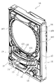
 game board 30 for entering a game ball flowing down the flowing space between the window portion 101 and the game board 30. By entering the starting prize winning device 33, the main control device 261 performs a lottery determination with a predetermined probability, and the game state is shifted to the special game state by the corresponding lottery, and at least once in the special game state. The variable winning device 32 is switched from the non-ball receiving state to the ball receiving state, and in the ball receiving state, a predetermined number of winning balls received in the receiving portion from the large winning opening 61 are detected by the detection sensor. In this way, a predetermined number of prize balls are paid out.

(特徴構成)
本パチンコ機10においては、図7ないし図34に示すように、遊技盤30の盤面を覆う前面扉として、前面枠セット14が内枠12に対し開閉自在に取り付けられている。内枠12は、前述の通りそれ自体が外枠11に開閉可能に軸支されており、したがってそれ自体が、遊技機本体側の部材である外枠11に軸支されているともいえるが、同時に、前面枠セット14を開閉可能に軸支する部材ともなっており、したがって前面枠セット14との関係においては遊技機本体側の部材となっている。換言すれば、外枠11に内枠12が軸支されるとともに内枠12に前面枠セット14が軸支されるという重層的な構造となっていて、内枠12はこの中間に位置しており、したがって内枠12は、軸支される側の部材となっているとともに、軸支する側の部材すなわち遊技機本体側の部材ともなっている。
(Feature configuration)
In the pachinko machine 10, as shown in FIGS. 7 to 34, a front frame set 14 is attached to the inner frame 12 so as to be openable and closable as a front door that covers the board surface of the game board 30. As described above, the inner frame 12 is pivotally supported by the outer frame 11 so as to be openable and closable. Therefore, it can be said that the inner frame 12 is pivotally supported by the outer frame 11 which is a member on the gaming machine main body side. At the same time, it is a member that pivotally supports the front frame set 14 so as to be openable and closable. Therefore, in relation to the front frame set 14, it is a member on the gaming machine main body side. In other words, the inner frame 12 is pivotally supported by the outer frame 11 and the front frame set 14 is pivotally supported by the inner frame 12, and the inner frame 12 is positioned in the middle. Therefore, the inner frame 12 is a member on the side that is pivotally supported, and is also a member on the side that is pivotally supported, that is, a member on the gaming machine main body side.

内枠12は、図7ないし図11に示すように、前記外枠11(図7ないし図34では図示省略)に嵌入し得る正面視矩形状であって前後にやや膨出する概略形状を有し、前記下皿ユニット13が配設される下端部より上の前側部分を、前面枠セット14が構成している。   As shown in FIGS. 7 to 11, the inner frame 12 is a rectangular shape in front view that can be fitted into the outer frame 11 (not shown in FIGS. 7 to 34), and has a schematic shape that slightly bulges back and forth. And the front frame set 14 comprises the front part above the lower end part by which the said lower pan unit 13 is arrange | positioned.

なお、内枠12の構成は前述した通りであり、図1および図2に示すようなものであるが、図7ないし図34では、明瞭化のため、前記上皿19や窓部101その他の細部は省略し、また下皿ユニット13を内枠12と一体的に表す等して、内枠12の構成および形状を大幅に簡略化・単純化している。   The structure of the inner frame 12 is as described above and is as shown in FIGS. 1 and 2, but in FIGS. 7 to 34, for the sake of clarity, the upper plate 19, the window portion 101, and the like. Details are omitted, and the configuration and shape of the inner frame 12 are greatly simplified and simplified by representing the lower tray unit 13 integrally with the inner frame 12.

図8に示すように、内枠12の右下部における遊技球発射ハンドル18の上方の位置には、シリンダ錠62が前方に露出するように配設されており、パチンコ機10の正面側から操作し得るようになっている。   As shown in FIG. 8, a cylinder lock 62 is disposed at a position above the game ball launching handle 18 in the lower right portion of the inner frame 12 so as to be exposed forward, and can be operated from the front side of the pachinko machine 10. It has come to be able to do.

シリンダ錠62は、図39および図40に示すように、鍵の挿入方向すなわち前後方向に沿って円筒状に延びる本体62Bと、本体62Bの後端に直交するように上下に延出するフランジ62Fと、フランジ62Fの上下端部からそれぞれ後方へ延出する軸62Dと、各軸62Dにそれぞれ外嵌された圧縮コイルバネ62Sとを有する構成となっている。   39 and 40, the cylinder lock 62 includes a main body 62B extending in a cylindrical shape along the key insertion direction, that is, the front-rear direction, and a flange 62F extending vertically so as to be orthogonal to the rear end of the main body 62B. And a shaft 62D extending rearward from the upper and lower ends of the flange 62F, and a compression coil spring 62S externally fitted to each shaft 62D.

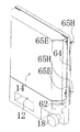
図9および図10に示すように、内枠12の裏面部における右側端縁部(図9および図10では左側端縁部)には、内枠係合部63が配設されており、これにより内枠12が外枠11に係合して閉じた状態(閉状態)に拘束されあるいはこの閉状態を解除され得るようになっている。   As shown in FIGS. 9 and 10, an inner frame engaging portion 63 is disposed at the right edge portion (the left edge portion in FIGS. 9 and 10) of the back surface of the inner frame 12. As a result, the inner frame 12 is engaged with the outer frame 11 and restrained in a closed state (closed state), or the closed state can be released.

内枠係合部63は、図9および図10に示すように、内枠12の裏面部における右側端縁部に沿って縦長に延びる基枠64と、基枠64にスライド可能に支持される係合片65とを有して構成されている。基枠64は、内枠12の上端近傍から中央のやや下方まで帯状に延びて内枠12の裏面に重ね合わせて固定される固定片64Fと、固定片64Fの外側縁(右側縁;図9および図10では左側縁)から垂直に延出する支持片64Sとを有して横断面L字形状となるように金属板を折曲して成形された基本構成を有する部材となっている。支持片64Sの延出端側半部は、固定片64Fの下端の位置よりもさらに下方へ延び、シリンダ錠62が配置された高さ位置より若干下方の位置が下端となっている。支持片64Sの延出端部は、全長にわたって固定片64F側(図9および図10では右側)へ横断面略U字状に折り返されて折返部が形成されている。さらに、支持片64Sにおける下端からシリンダ錠62より若干上方の高さ位置までの部分は、支持片64Sの上部と同一の幅となるように前方(図9および図10では後方)へ延びて図39および図40に示すように右側片64Rを形成し、その先端から、固定片64Fと同方向(図9および図40では右方向)へ同一幅となるように垂直に延びて中央片64Cを形成し、さらにその先端から支持片64Sと同方向(図9および図40では前方向)へ延出して左側片64Lを形成し、これら右側片64R、中央片64Cおよび左側片64Lにより全体として横断面概略コ字形状の伝達機構支持部64Tが形成されている。   As shown in FIGS. 9 and 10, the inner frame engaging portion 63 is slidably supported by a base frame 64 that extends vertically along the right end edge of the back surface portion of the inner frame 12 and a base frame 64. And an engaging piece 65. The base frame 64 extends in a belt shape from the vicinity of the upper end of the inner frame 12 to a slightly lower center and is fixed by being overlapped on the back surface of the inner frame 12, and the outer edge (right edge; FIG. 9) of the fixed piece 64F. And a support piece 64S extending vertically from the left edge in FIG. 10 and having a basic structure formed by bending a metal plate so as to have an L-shaped cross section. The extended end side half of the support piece 64S extends further downward than the position of the lower end of the fixed piece 64F, and the lower end is a position slightly below the height position where the cylinder lock 62 is disposed. The extending end portion of the support piece 64S is folded back to the fixed piece 64F side (right side in FIGS. 9 and 10) in a substantially U-shaped cross section over the entire length to form a folded portion. Further, the portion of the support piece 64S from the lower end to the height position slightly above the cylinder lock 62 extends forward (rearward in FIGS. 9 and 10) so as to have the same width as the upper portion of the support piece 64S. 39 and 40, the right piece 64R is formed, and the central piece 64C is extended from the tip thereof in the same direction as the fixed piece 64F (right direction in FIGS. 9 and 40) so as to have the same width. Further, the left side piece 64L is formed by extending from the tip in the same direction as the support piece 64S (the front direction in FIGS. 9 and 40) to form the left side piece 64L. The right side piece 64R, the central piece 64C and the left side piece 64L are crossed as a whole. A transmission mechanism support portion 64T having a generally U-shaped surface is formed.

伝達機構支持部64Tは、図39および図40に示すように、厳密には、支持片64Sから一旦外側(右側)へ垂直に若干延出してから、前方へ延びて右側片64Rを形成しており、一方、左側片64Lの延出端(後端)も右側へ垂直に若干延出している。即ち、伝達機構支持部64Tは、厳密には、横断面概略コ字形状の両端が互いに対向する方向に若干延出した横断面概略C字形状となっている。   Strictly speaking, as shown in FIGS. 39 and 40, the transmission mechanism support portion 64T extends slightly from the support piece 64S to the outside (right side) vertically and then extends forward to form the right side piece 64R. On the other hand, the extending end (rear end) of the left piece 64L also extends slightly to the right. That is, strictly speaking, the transmission mechanism support portion 64T has a substantially C-shaped cross section in which both ends of a substantially U-shaped cross section are slightly extended in a direction facing each other.

係合片65は、図9および図10に示すように、基枠64の支持片64Sの長さより若干小さい長さおよび支持片64Sの幅の半分程度の幅を有するように支持片64Sに沿って上下に延びる概略帯状の基本形状を有し、下端よりやや上方の位置および上端の位置にはそれぞれ、後側縁から後方へ側面視概略鋭角に先細りする形状に延出するフック65Hが形成された金属板よりなる部材となっている。図35ないし図38等によく表れているように、上下各フック65Hにおける上側縁の基端部には、内側(下側)へ矩形状に凹入する鉤部65Eが形成されている。さらに、図39および図40に示すように、係合片65の下端と下側のフック65Hとの間には、前側縁から矩形状に凹入する係合切欠65Rが形成されている。   As shown in FIGS. 9 and 10, the engagement piece 65 has a length slightly smaller than the length of the support piece 64 </ b> S of the base frame 64 and a width about half the width of the support piece 64 </ b> S along the support piece 64 </ b> S. A hook 65H is formed at the position slightly above and below the lower end and at the upper end, extending in a shape that tapers from the rear edge toward the rear in a substantially acute angle in a side view. It is a member made of a metal plate. As clearly shown in FIG. 35 to FIG. 38 and the like, a flange 65E that is recessed inward (downward) in a rectangular shape is formed at the base end of the upper edge of each of the upper and lower hooks 65H. Further, as shown in FIGS. 39 and 40, an engagement notch 65R that is recessed in a rectangular shape from the front edge is formed between the lower end of the engagement piece 65 and the lower hook 65H.

図9および図10に示すように、基枠64の支持片64Sにおける前側端縁部すなわち折返端縁部の下端よりやや上方の位置および上端の位置にはそれぞれ、係合片65のフック65Hの上下幅よりやや長く上下に延びるスリットが形成されており、係合片65は、上下各フック65Hを上下各スリットから後方へ突出させるようにして、支持片64Sの折返部内に嵌入されている。支持片64Sの下端部および上端近傍部にはそれぞれ、支持片64Sに局部的にコ字状に切り込みを入れて垂直に引き起こすようにして複数の掛止片が形成されており、これら掛止片により係合片65の前側縁が掛止されて前方への移動が規制されている。これにより、係合片65が、上下にスライド可能に支持片64Sに支持されている。図9に示すように、係合片65の上端よりやや下方と、基枠64における固定片64Fの上端部との間には引っ張りコイルバネ66が懸架されており、これにより係合片65が上方に引っ張られるように付勢されている。外枠11の右側片における内側面の上下には、係合片65の上下各フック65Hに対応する位置に受け金具がそれぞれ固定されており(図示せず)、外枠11に対して内枠12を閉じていくと、上下各フック65Hの斜線状の上側縁が受け金具に当接してカム状に機能し、引っ張りコイルバネ66の付勢力に抗して係合片65が次第に引き下げられていき、各フック65Hの鉤部65Eが受け金具の位置に到達すると、係合片65が引っ張りコイルバネ66の付勢力により再び上方に引き上げられ、各フック65Hの鉤部65Eが受け金具に係合して、これにより外枠11に対して内枠12が閉じた状態に拘束される。   As shown in FIGS. 9 and 10, the hook 65H of the engagement piece 65 is located at a position slightly above and below the lower end of the front end edge of the support piece 64S of the base frame 64, that is, the folded end edge. A slit that is slightly longer than the vertical width and extends vertically is formed, and the engagement piece 65 is fitted into the folded portion of the support piece 64S so that the upper and lower hooks 65H protrude rearward from the upper and lower slits. A plurality of latching pieces are formed at the lower end portion and the vicinity of the upper end portion of the support piece 64S, respectively, so that the support piece 64S is locally cut into a U-shape and vertically caused. As a result, the front side edge of the engagement piece 65 is hooked and the forward movement is restricted. Thereby, the engagement piece 65 is supported by the support piece 64S so that it can slide up and down. As shown in FIG. 9, a tension coil spring 66 is suspended slightly below the upper end of the engagement piece 65 and the upper end portion of the fixed piece 64 </ b> F in the base frame 64. It is urged to be pulled. On the upper and lower sides of the inner surface of the right side piece of the outer frame 11, receiving metal fittings are fixed at positions corresponding to the upper and lower hooks 65 </ b> H of the engagement piece 65 (not shown). When 12 is closed, the upper edge of the diagonal line of each of the upper and lower hooks 65H abuts on the receiving metal and functions as a cam, and the engaging piece 65 is gradually pulled down against the urging force of the tension coil spring 66. When the hook portion 65E of each hook 65H reaches the position of the catch metal, the engagement piece 65 is again pulled upward by the urging force of the tension coil spring 66, and the hook portion 65E of each hook 65H is engaged with the catch metal. Thus, the inner frame 12 is restrained to the closed state with respect to the outer frame 11.

図40に示すように、シリンダ錠62のフランジ62Fの中央からは、鍵の操作により回転する回転軸62Rが後方(図40では前方)へ突出し、回転軸62Rの先端には、短尺の円筒状の回転子67が同軸となるように固定されている。回転子67の後端からは、軸方向に直交するように上方へ概略台形状に拡がる形状の係合突片67Eが延出している。基枠64の伝達機構支持部64Tにおける中央片64Cの中央部には、回転子67より僅かに大径の円形孔64Pが穿設されており、この円形孔64Pに回転子67が挿通されて回転自在にかつ前後に移動自在に保持されている。また、伝達機構支持部64Tの中央片64Cにおける円形孔64Pの上方および下方にはそれぞれ軸挿通孔が穿設されており、各軸挿通孔にシリンダ錠62の上下の軸62Dがそれぞれ挿通され、各軸挿通孔から後方へ突出した軸62Dの先端にナット62Nがそれぞれ固定されている。伝達機構支持部64Tの中央片64Cとシリンダ錠62のフランジ62Fとの間には圧縮コイルバネ62Sがあってシリンダ錠62を前方へ付勢するが、軸62Dの先端のナット62Nにより、シリンダ錠62が限度以上に前方へ移動しないように、即ち伝達機構支持部64Tから離脱しないように規制される。この構造により、シリンダ錠62は通常、ナット62Nによる規制範囲内で圧縮コイルバネ62Sの付勢力により最大限に前方へ移動した状態で保持されるようになっている。   As shown in FIG. 40, from the center of the flange 62F of the cylinder lock 62, a rotating shaft 62R that rotates by the operation of the key protrudes rearward (frontward in FIG. 40), and the tip of the rotating shaft 62R has a short cylindrical shape. The rotor 67 is fixed so as to be coaxial. From the rear end of the rotor 67, an engaging projection piece 67E extending upward in a substantially trapezoidal shape extends so as to be orthogonal to the axial direction. A circular hole 64P having a slightly larger diameter than the rotor 67 is formed in the central portion of the central piece 64C of the transmission mechanism support portion 64T of the base frame 64, and the rotor 67 is inserted into the circular hole 64P. It is held so that it can rotate and move back and forth. Further, shaft insertion holes are respectively formed above and below the circular holes 64P in the central piece 64C of the transmission mechanism support portion 64T, and the upper and lower shafts 62D of the cylinder lock 62 are respectively inserted into the shaft insertion holes. Nuts 62N are fixed to the ends of the shafts 62D protruding rearward from the respective shaft insertion holes. There is a compression coil spring 62S between the central piece 64C of the transmission mechanism support 64T and the flange 62F of the cylinder lock 62 to urge the cylinder lock 62 forward, but the cylinder lock 62 is urged by the nut 62N at the tip of the shaft 62D. Is prevented from moving forward beyond the limit, that is, so as not to be detached from the transmission mechanism support portion 64T. With this structure, the cylinder lock 62 is normally held in a state where it is moved forward to the maximum by the urging force of the compression coil spring 62S within the restricted range of the nut 62N.

基枠64の伝達機構支持部64Tにおける左側片64Lおよび右側片64Rの内側には、左側スライダ68Lおよび右側スライダ68Rが嵌装されている。左側スライダ68Lは、伝達機構支持部64Tにおける左側片64Lの幅より若干小さい幅を有して上下に帯状に延びる金属板よりなる部材となっている。左側スライダ68Lの上端部は右方へ直角に折曲されてフック片681Lが形成され、フック片681Lの先端縁部は僅かな幅だけ下方に直角に折曲されており、またフック片681Lの先端縁中央付近から基端縁(左側端縁)近傍まで内側(左側)へ延びるスリットが形成されている。左側スライダ68Lの高さ方向中央部には、後側縁から縦長の矩形状に凹入する掛止切欠682Lが形成されている。右側スライダ68Rは、左側スライダ68Lと左右対称に構成されており、同様のフック片681Rおよび掛止切欠682Rが形成されている。   A left slider 68L and a right slider 68R are fitted inside the left piece 64L and the right piece 64R in the transmission mechanism support 64T of the base frame 64. The left slider 68L is a member made of a metal plate having a width slightly smaller than the width of the left piece 64L in the transmission mechanism support 64T and extending vertically in a band shape. The upper end of the left slider 68L is bent at a right angle to the right to form a hook piece 681L. The tip edge of the hook piece 681L is bent at a right angle downward by a slight width, and the hook piece 681L A slit extending inward (left side) from the vicinity of the center of the front end edge to the vicinity of the base end edge (left end edge) is formed. A latching cutout 682L that is recessed from the rear side edge into a vertically long rectangular shape is formed at the center in the height direction of the left slider 68L. The right slider 68R is configured to be bilaterally symmetric with the left slider 68L, and the same hook piece 681R and latching notch 682R are formed.

基枠64の伝達機構支持部64Tにおける左側片64Lの高さ方向中央部には、後側縁から縦長の矩形状に凹入する矩形切欠641Lが形成され、矩形切欠641Lの内奥縁(前側縁)の上端部には、後方へ延出して内側(右側)へ平面視略U字状に折り返されて前方へ延びる掛止小片642Lが形成されている。図38に示すように、左側スライダ68Lは、フック片681Lを右側(図38では左側)へ向けた体勢で伝達機構支持部64Tにおける左側片64Lの内側に嵌入される。このとき、伝達機構支持部64Tにおける左側片64Lの延出端(後端)が前述の通り右側へ若干延出しており、この延出部により、左側スライダ68Lの後側縁が支承される。また、上述のように左側スライダ68Lを伝達機構支持部64Tにおける左側片64Lの内側に嵌入した状態で、左側スライダ68Lにおける掛止切欠682Lの内奥縁(前側縁)を内側に挟み込むようにして、伝達機構支持部64Tにおける左側片64Lの掛止小片642Lが平面視略U字状に折り返され、これにより掛止小片642Lが掛止切欠682Lの内奥縁(前側縁)に掛止する。こうして、左側スライダ68Lが伝達機構支持部64Tにおける左側片64Lの内側に上下にスライド自在に保持され、このとき、左側スライダ68Lにおける掛止切欠682Lの上側縁および下側縁に、伝達機構支持部64Tにおける左側片64Lの掛止小片642Lが当接し、左側スライダ68Lのそれ以上の下方および上方への移動が規制される。即ち、伝達機構支持部64Tにおける左側片64Lの掛止小片642Lが、当該左側片64Lの内側に左側スライダ68Lを保持するとともに、左側スライダ68Lの上下の移動限界を規定するストッパとしても機能するようになっている。   A rectangular notch 641L that is recessed from the rear edge into a vertically long rectangular shape is formed at the center in the height direction of the left piece 64L in the transmission mechanism support portion 64T of the base frame 64, and an inner inner edge (front side) of the rectangular notch 641L. A latching piece 642L is formed at the upper end of the edge, and extends rearward and folded back inward (right side) in a substantially U shape in plan view to extend forward. As shown in FIG. 38, the left slider 68L is fitted inside the left piece 64L of the transmission mechanism support portion 64T with the posture in which the hook piece 681L faces the right side (left side in FIG. 38). At this time, the extension end (rear end) of the left piece 64L in the transmission mechanism support 64T extends slightly to the right as described above, and the rear edge of the left slider 68L is supported by this extension. Further, as described above, with the left slider 68L fitted inside the left piece 64L of the transmission mechanism support portion 64T, the inner back edge (front edge) of the latching notch 682L of the left slider 68L is sandwiched inside. Then, the latching small piece 642L of the left-side piece 64L in the transmission mechanism support 64T is folded back in a substantially U shape in plan view, whereby the latching small piece 642L is latched on the inner inner edge (front side edge) of the latching notch 682L. Thus, the left slider 68L is slidably held up and down inside the left piece 64L in the transmission mechanism support portion 64T. At this time, the transmission mechanism support portion is placed on the upper and lower edges of the latching cutout 682L in the left slider 68L. The latching small piece 642L of the left side piece 64L at 64T abuts, and the further downward and upward movement of the left side slider 68L is restricted. That is, the latching piece 642L of the left piece 64L in the transmission mechanism support 64T holds the left slider 68L inside the left piece 64L, and also functions as a stopper that defines the upper and lower movement limits of the left slider 68L. It has become.

右側スライダ68Rは、左側スライダ68Lと左右対称の体勢で、伝達機構支持部64Tにおける右側片64Rの内側に嵌入される。このとき、右側片64Rの後端は、左方へ若干延出して支持片64Sに連続しており、この延出部により、右側スライダ68Rの後側縁が支承される。また、右側スライダ68Rには、掛止部材69が装着される。掛止部材69は、図39および図40に示すように、それぞれ上下に帯状に延びる右側板と左側板とが、前後方向に平行な体勢(伝達機構支持部64Tにおける右側片64Rに平行な体勢)で、若干間隔をおいて対向配置され、右側板および左側板の後側端縁の上端部同士が後方へやや延出して平面視略U字形状をなして一体的に連続し、これにより折返連絡部69Fが形成された構成となっている。また、右側板の前側端縁の上端部は外側(右側)へ直角に延出して掛止片69Eが形成され、左側板の前側端縁の下端部は外側(左側)へ直角に延出して矩形状の接合片69Cが形成されている。掛止部材69は、図36ないし図38に示すように、右側スライダ68Rにおける掛止切欠682Rの内奥縁(前側縁)に折返連絡部69Fを掛止させつつ、右側板と左側板との間に右側スライダ68Rを挟み込むようにして装着される。一方、図39および図40に示すように、伝達機構支持部64Tの中央片64Cにおける円形孔64Pの右上方には、右側片64Rに隣接するようにして、矩形の掛止小孔64Dが穿設されている。右側スライダ68Rは、上述のようにして掛止部材69を装着した状態で、伝達機構支持部64Tにおける右側片64Rの内側に嵌入され、掛止部材69の掛止片69Eが伝達機構支持部64Tの掛止小孔64Dに挿入されて掛止されるとともに、掛止部材69の接合片69Cが伝達機構支持部64Tにおける中央片64Cの内側面に溶接、ネジ止め等により接合され、これにより掛止部材69が伝達機構支持部64Tに固定される。こうして、右側スライダ68Rが伝達機構支持部64Tにおける右側片64Rの内側に上下にスライド自在に保持され、このとき、右側スライダ68Rにおける掛止切欠682Rの上側縁および下側縁に、掛止部材69の折返連絡部69Fが当接し、右側スライダ68Rのそれ以上の下方および上方への移動が規制される。即ち、掛止部材69の折返連絡部69Fが、上述の伝達機構支持部64Tにおける左側片64Lの掛止小片642Lの場合と同様に、当該右側片64Rの内側に右側スライダ68Rを保持するとともに、右側スライダ68Rの上下の移動限界を規定するストッパとしても機能するようになっている。   The right slider 68R is fitted to the inside of the right piece 64R in the transmission mechanism support portion 64T with a symmetric posture with the left slider 68L. At this time, the rear end of the right piece 64R extends slightly to the left and continues to the support piece 64S, and the rear edge of the right slider 68R is supported by the extended portion. Further, a latch member 69 is attached to the right slider 68R. As shown in FIGS. 39 and 40, the latch member 69 has a posture in which the right side plate and the left side plate extending vertically in the vertical direction are parallel to the front-rear direction (the posture parallel to the right piece 64R in the transmission mechanism support portion 64T). ), And the upper end portions of the rear side edges of the right side plate and the left side plate slightly extend backward to form a substantially U-shape in plan view and are integrally continuous. It is the structure in which the return communication part 69F was formed. Further, the upper end of the front edge of the right side plate extends to the outside (right side) at a right angle to form a retaining piece 69E, and the lower end of the front side edge of the left side plate extends to the outside (left side) at a right angle. A rectangular joining piece 69C is formed. As shown in FIGS. 36 to 38, the hooking member 69 holds the folding connection portion 69F on the inner back edge (front edge) of the hooking notch 682R in the right slider 68R, while The right slider 68R is mounted between them. On the other hand, as shown in FIGS. 39 and 40, a rectangular latching small hole 64D is formed on the upper right side of the circular hole 64P in the central piece 64C of the transmission mechanism support portion 64T so as to be adjacent to the right piece 64R. It is installed. The right slider 68R is fitted inside the right piece 64R of the transmission mechanism support portion 64T in the state where the latch member 69 is mounted as described above, and the latch piece 69E of the latch member 69 is inserted into the transmission mechanism support portion 64T. The joint piece 69C of the latch member 69 is joined to the inner surface of the center piece 64C in the transmission mechanism support portion 64T by welding, screwing, or the like. The stop member 69 is fixed to the transmission mechanism support portion 64T. Thus, the right slider 68R is slidably held up and down inside the right piece 64R in the transmission mechanism support portion 64T. At this time, the latch member 69 is placed on the upper and lower edges of the latch cutout 682R in the right slider 68R. , And the further downward movement and upper movement of the right slider 68R are restricted. That is, the folding contact portion 69F of the latch member 69 holds the right slider 68R inside the right piece 64R, as in the case of the latch piece 642L of the left piece 64L in the transmission mechanism support 64T described above, It also functions as a stopper that defines the upper and lower movement limits of the right slider 68R.

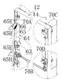
図9および図10に示すように、内枠12の右上、右下、左上および左下の各隅部には、右上軸支部70A、右下軸支部70B、左上軸支部70Cおよび左下軸支部70Dがそれぞれ配設されており、これにより前面枠セット14が内枠12に軸支されるようになっている。   As shown in FIGS. 9 and 10, at the upper right, lower right, upper left and lower left corners of the inner frame 12, there are an upper right shaft support portion 70A, a lower right shaft support portion 70B, an upper left shaft support portion 70C and a lower left shaft support portion 70D. The front frame set 14 is pivotally supported by the inner frame 12.

右上軸支部70Aは、図46および図47に示すように、内枠12側に配設される軸受側機構71Rと、前面枠セット14側に配設される軸側機構71Sとを備える基本構成となっている。軸受側機構71Rは、可動部材72が基材73に保持された構成を有している。可動部材72は、図41および図45に示すように、水平に配置され、垂直方向に貫通する軸挿通孔を有する平板状の基部72Bから、前方へ作動片72Fが延出し、左方へレバー片72Lが延出した構成となっている。作動片72Fの先端近傍には、図45に示すように、右側縁から平面視半円状に凹入する軸嵌合切欠72Rが形成され、図41に示すように、軸嵌合切欠72Rより基端側(基部72B側)には、作動片72Fの右側縁から、厚さ方向に一段下方へ下がってから右方へ延出し、さらにその先端から前方へ延出する押圧片72Pが形成されている。押圧片72Pの前端縁は、軸嵌合切欠72Rの基端側(基部72B側)端の位置から、軸嵌合切欠72Rの円周方向よりも外側へ次第に拡がる弧状をなすように延びている。即ち、軸嵌合切欠72Rの基端側(基部72B側)端の位置から、軸嵌合切欠72Rの径より大径の円弧形状をなすように押圧片72Pの前端縁が延びている。レバー片72Lの先端部は後方へ延出してすぐ上方へ立ち上がるように延出し、さらにその右端が右方へ延出して、これによりレバー片72Lに対し垂直であってレバー片72Lの後側縁に沿って基端側(基部72B側)へ折り返すように延びる掛止片72Eが形成されている。掛止片72Eの下端縁中央部には、矩形状に凹入する切欠が形成されている。   As shown in FIGS. 46 and 47, the upper right shaft support portion 70A includes a bearing side mechanism 71R disposed on the inner frame 12 side and a shaft side mechanism 71S disposed on the front frame set 14 side. It has become. The bearing side mechanism 71 </ b> R has a configuration in which the movable member 72 is held by the base material 73. As shown in FIG. 41 and FIG. 45, the movable member 72 is disposed horizontally, and an operating piece 72F extends forward from a flat base 72B having a shaft insertion hole penetrating in the vertical direction. The piece 72L extends. As shown in FIG. 45, a shaft fitting notch 72R that is recessed in a semicircular shape in plan view from the right edge is formed in the vicinity of the distal end of the operating piece 72F. On the base end side (base portion 72B side), a pressing piece 72P extending from the right edge of the operating piece 72F to the right after being lowered by one step in the thickness direction and further extending forward from the tip is formed. ing. The front end edge of the pressing piece 72P extends from the position of the base end side (base portion 72B side) end of the shaft fitting notch 72R so as to form an arc shape that gradually expands outward from the circumferential direction of the shaft fitting notch 72R. . That is, the front end edge of the pressing piece 72P extends from the position of the base end side (base portion 72B side) end of the shaft fitting notch 72R so as to form an arc shape having a larger diameter than the diameter of the shaft fitting notch 72R. The front end of the lever piece 72L extends rearward and immediately rises upward, and the right end of the lever piece 72L extends rightward, thereby being perpendicular to the lever piece 72L and the rear edge of the lever piece 72L. A latch piece 72E is formed so as to extend back to the base end side (base portion 72B side). A notch that is recessed in a rectangular shape is formed at the center of the lower end edge of the retaining piece 72E.

基材73は、可動部材72の基部72Bおよびレバー片72Lに対応する左右方向の長さおよび前後方向の幅を有して水平に拡がる基部73Bを備え、基部73Bの右端部からは、前方へ固定作動片73Fが延出している。固定作動片73Fの先端近傍には、左側縁から平面視半円状に凹入する軸嵌合切欠73Rが形成されている。基部73Bの右端部には、垂直方向に貫通する軸挿通孔が穿設されている。基部73Bにおける後側縁の右側半部からは、上方へ矩形状の接合片73Cが延出し、接合片73Cの4隅部にはネジ挿通孔が穿設されている。基部73Bにおける後側縁の左側半部は、接合片73Cよりもやや後方まで延出し、その延出端縁の両端部から、側面視概略コ字状をなして後方へ膨出してから上方へやや延びる挟持片73Pがそれぞれ延出している。基部73Bの上には、可動部材72の基部72Bおよびレバー片72Lが載置され、この状態で軸挿通孔にリベットが挿通されて固定され、これにより可動部材72が基材73に回動可能に支持される。   The base material 73 includes a base portion 73B having a horizontal length and a front-rear width corresponding to the base portion 72B and the lever piece 72L of the movable member 72 and extending horizontally, and forward from the right end portion of the base portion 73B. The fixed operation piece 73F extends. A shaft fitting notch 73R that is recessed in a semicircular shape in plan view from the left edge is formed in the vicinity of the tip of the fixed operating piece 73F. A shaft insertion hole penetrating in the vertical direction is formed in the right end portion of the base portion 73B. From the right half of the rear edge of the base 73B, a rectangular joining piece 73C extends upward, and screw insertion holes are drilled at the four corners of the joining piece 73C. The left half of the rear edge of the base portion 73B extends slightly rearward from the joining piece 73C, and bulges rearward from both ends of the extended edge in a substantially U shape in side view and then upwards. Slightly extending sandwiching pieces 73P extend respectively. On the base 73B, the base 72B of the movable member 72 and the lever piece 72L are placed, and in this state, the rivet is inserted into the shaft insertion hole and fixed, so that the movable member 72 can be rotated on the base material 73. Supported by

図48および図49に示すように、内枠12の右上の隅部における上端よりやや下方の位置には、右端近傍から内側(左側)へ横長に延びる貫通部12Pが穿設されており、可動部材72および基材73は、作動片72Fおよび固定作動片73Fと、基部72B、73Bおよびレバー片72Lの前側部を貫通部12Pに挿通するようにして、内枠12の右上の隅部に後方から嵌着され、内枠12の後側面における貫通部12Pの上方に、基材73の接合片73Cがネジ止めにより接合されて固定される。図48に示すように、貫通部12Pの左側半部は、前方へ直方体状に膨出する突出部12Eが形成されており、可動部材72および基材73における作動片72Fより左側の半部が突出部12Eにより前方から覆われるようになっている。また、図49に示すように、貫通部12Pの左側半部(図49では右側半部)は上方へやや幅広となっている。   As shown in FIGS. 48 and 49, a penetrating portion 12P that extends horizontally from the vicinity of the right end to the inside (left side) is formed at a position slightly below the upper end of the upper right corner of the inner frame 12, and is movable. The member 72 and the base material 73 are rearwardly moved to the upper right corner of the inner frame 12 so that the operating pieces 72F and the fixed operating pieces 73F, and the base portions 72B and 73B and the front side portions of the lever pieces 72L are inserted into the penetrating portions 12P. The joining piece 73C of the base material 73 is joined and fixed to the upper side of the through portion 12P on the rear side surface of the inner frame 12 by screwing. As shown in FIG. 48, the left half of the penetrating portion 12P is formed with a protrusion 12E that bulges forward in a rectangular parallelepiped shape, and the left half of the movable member 72 and the base member 73 from the operating piece 72F is The protrusion 12E covers the front. As shown in FIG. 49, the left half of the penetrating portion 12P (the right half in FIG. 49) is slightly wider upward.

図48および図49に示すように、基材73の接合片73Cの直下には、矩形状の垂直片の下端から矩形状の水平片が後方へ延出するブラケット74Aが配置され、内枠12の後側面における貫通部12Pの下方に垂直片が接合されて固定される。ブラケット74Aの水平片における後側縁の中央部には、内側(前側)へ凹入する切欠が形成されている。ブラケット74Aと基材73との間には可撓性を有するチューブ75Aが架設されている。チューブ75Aの両端には、2つのフランジ部が間隔をおいて形成された構成を有する端部材75Eが固定されており、一方の端部材75Eが両フランジ部の間でブラケット74Aの切欠に嵌入され、これより上方に延びたチューブ75Aの上部が左上方へ曲げられて先端が前方へ向けられ、他方の端部材75Eが両フランジ部の間で基材73の両挟持片73Pの間に嵌入されている。   As shown in FIGS. 48 and 49, a bracket 74A in which a rectangular horizontal piece extends rearward from the lower end of the rectangular vertical piece is disposed immediately below the joining piece 73C of the base material 73. A vertical piece is bonded and fixed below the through-hole 12P on the rear side surface. A notch that is recessed inward (front side) is formed at the center of the rear edge of the horizontal piece of the bracket 74A. A flexible tube 75 </ b> A is installed between the bracket 74 </ b> A and the base material 73. An end member 75E having a structure in which two flange portions are formed at an interval is fixed to both ends of the tube 75A, and one end member 75E is fitted into the notch of the bracket 74A between the both flange portions. The upper part of the tube 75A extending upward is bent leftward and the front end is directed forward, and the other end member 75E is inserted between the sandwiching pieces 73P of the base material 73 between both flange portions. ing.

チューブ75Aには第1ワイア76Aが下方から挿通され、第1ワイア76Aの先端部は可動部材72における掛止片72Eの切欠に挿通され、その先端には短尺の円柱状の留具77が固定されており、これにより第1ワイア76Aの先端が可動部材72の掛止片72Eに掛止するようになっている。可動部材72の掛止片72Eとチューブ75Aの一方の端部材75Eとの間では、第1ワイア76Aに圧縮コイルバネ78が外嵌されており、これにより可動部材72が上面視反時計回り方向に付勢されている。このように可動部材72が圧縮コイルバネ78で付勢されることにより、図45に示すように、可動部材72の作動片72Fと基材73の固定作動片73Fとが通常は合わさって閉じた体勢に保持されており、これにともない、可動部材72の軸嵌合切欠72Rと基材73の軸嵌合切欠73Rとが一体となって円形の軸挿通孔を構成している。また、可動部材72の作動片72Fおよび基材73の固定作動片73Fはそれぞれ、先端が平面視において丸く先細りするように形成されており、したがって上記のようにこれら作動片72Fと固定作動片73Fとが閉じた体勢においては、これらの先端部が一体となって、両側から中央にかけて内側(後側)へ平面視概略谷状に凹入する形状をなしている。   A first wire 76A is inserted into the tube 75A from below, and a distal end portion of the first wire 76A is inserted into a notch of a latching piece 72E in the movable member 72, and a short cylindrical fastener 77 is fixed to the distal end. As a result, the leading end of the first wire 76 </ b> A is engaged with the engaging piece 72 </ b> E of the movable member 72. A compression coil spring 78 is externally fitted to the first wire 76A between the latching piece 72E of the movable member 72 and one end member 75E of the tube 75A, whereby the movable member 72 is counterclockwise as viewed from above. It is energized. As shown in FIG. 45, the movable member 72 is biased by the compression coil spring 78 in this manner, so that the working piece 72F of the movable member 72 and the fixed working piece 73F of the base material 73 are usually joined together and closed. Accordingly, the shaft fitting notch 72 </ b> R of the movable member 72 and the shaft fitting notch 73 </ b> R of the base material 73 are integrated to form a circular shaft insertion hole. Further, each of the operating piece 72F of the movable member 72 and the fixed operating piece 73F of the base material 73 is formed so that the tip thereof is rounded and tapered in a plan view. Therefore, as described above, the operating piece 72F and the fixed operating piece 73F are formed. In the closed body posture, these tip portions are integrated to form a concave shape in a generally valley shape in plan view from both sides to the center (rear side).

軸側機構71Sは、図42、図44、図46および図47に示すように、ケーシング81と前面枠セット14との間に可動軸部材82が移動可能に保持された構成となっている。ケーシング81は、図46および図47に示すように、正面視概略横長の矩形状で前後方向の寸法がやや小さい直方体(即ち正面視概略横長の矩形状で前後方向にやや厚みのある平板)状であって、前側面が全面的に開放された中空形状を有している。上側壁、左側壁および下側壁における4箇所の端部(右上、左上、左下および右下の各端部)はそれぞれ、断面弧状で前後に延びるように内側へ凹入し、その前端面が壁で閉塞されてネジ挿通孔が穿設され、これによりネジ挿通部81Sが形成されている。右上および左上の両ネジ挿通部81Sの間の上側壁には、概略横長の長方形の右下および左下の隅部が丸く角落ちした断面形状で前後に延びる台形状となるように内側へ凹入する充填部81Fが形成されている。充填部81Fの前面はケーシング81の前側端の位置よりも若干内側(後側)に後退した位置にあって閉塞されており、充填部81Fの後端はケーシング81の後側壁に突き当たって一体的に連続している。また、ケーシング81の上側壁からの充填部81Fの凹入深さは両側のネジ挿通部81Sの凹入深さと同一となっている。一方、左下および右下の両ネジ挿通部81Sの間の下側壁には、上記充填部81Fと上下対称となるように充填部81Fが形成されている。ケーシング81の右側壁における前側端縁の中央部から、後側壁の中央部にかけて、同一幅で横断面L字状に延びる動作用切欠81Pが形成されている。   As shown in FIGS. 42, 44, 46 and 47, the shaft-side mechanism 71 </ b> S has a configuration in which a movable shaft member 82 is movably held between the casing 81 and the front frame set 14. As shown in FIGS. 46 and 47, the casing 81 has a rectangular shape that is substantially horizontally long when viewed from the front, and has a rectangular parallelepiped shape that is slightly smaller in the front-rear direction (that is, a flat plate that is generally horizontally long when viewed from the front and is slightly thick in the front and rear direction). And it has the hollow shape where the front side surface was opened completely. The four end portions (upper right, upper left, lower left and lower right ends) of the upper side wall, the left side wall, and the lower side wall are recessed inward so as to extend in the front-rear direction in a cross-sectional arc shape, and the front end surface is a wall. The screw insertion hole 81S is formed by forming a screw insertion hole. The upper side wall between the upper right and upper left screw insertion portions 81S is recessed inward so as to form a trapezoidal shape extending in the front-rear direction with a rounded and rounded corner at the lower right and lower left corners of a roughly oblong rectangle. A filling portion 81F is formed. The front surface of the filling part 81F is closed at a position slightly retracted inward (rear side) from the position of the front end of the casing 81, and the rear end of the filling part 81F hits the rear side wall of the casing 81 so as to be integrated. It is continuous. Moreover, the recessed depth of the filling portion 81F from the upper side wall of the casing 81 is the same as the recessed depth of the screw insertion portions 81S on both sides. On the other hand, a filling portion 81F is formed on the lower side wall between the lower left and lower right screw insertion portions 81S so as to be vertically symmetrical with the filling portion 81F. An operation notch 81P extending in the shape of an L-shaped cross section with the same width is formed from the center portion of the front side edge of the right side wall of the casing 81 to the center portion of the rear side wall.

可動軸部材82は、正面視概略矩形状であって右側縁中央部が内側へ概略矩形状に凹入して全体として正面視概略C字形状をなす板状部材82Bを有し、板状部材82Bの右上部および右下部において右方へ延びる両片の先端部が、それぞれ前側で左方へ巻回するようにして円柱状に形成され、これら両円柱状部の中心に、回転軸82Sの両端部が巻き込むようにして固定された構成となっている。   The movable shaft member 82 has a plate-like member 82B having a generally rectangular shape when viewed from the front and having a central portion on the right edge recessed inwardly in a generally rectangular shape to form a generally C-shape when viewed from the front as a whole. The tip portions of both pieces extending rightward in the upper right portion and lower right portion of 82B are formed in a cylindrical shape so as to be wound leftward on the front side, respectively. Both ends are fixed so as to be wound.

可動軸部材82は、支持部材83に固定される。支持部材83は、正面視概略矩形状であって前後方向の寸法がやや小さい概略ブロック(直方体)状体の右側縁中央部が内側へ概略矩形状に凹入し、全体として、可動軸部材82における円柱状部以外の部位にほぼ対応する正面視概略C字形状の部材となっている。支持部材83の後上側端縁および後下側端縁はそれぞれ上方および下方へやや延出して突条83Rが形成されている。支持部材83の高さ方向中央部には、前側面から縦断面矩形状に内側(後側)へ凹入し、左側面から中央近傍まで水平に延びる溝部83Gが形成されている。支持部材83の後側面における4隅部にはそれぞれネジ穴が形成され、右上および左上の両ネジ穴の間ならびに右下および左下の両ネジ穴の間にはそれぞれボスが突設されている。可動軸部材82の板状部材82Bには、支持部材83のネジ穴およびボスに対応する位置にそれぞれネジ挿通孔およびボス孔が穿設されており、ボス孔にボスを挿入して位置決めし、ネジ挿通孔を通してネジ穴にネジ84を螺入することにより、可動軸部材82が支持部材83にネジ固定される。   The movable shaft member 82 is fixed to the support member 83. The support member 83 has a generally rectangular shape when viewed from the front, and a central portion of the right edge of a roughly block (cuboid) having a slightly smaller size in the front-rear direction is recessed inwardly in a generally rectangular shape. It is the member of the general | schematic C-shape of the front view substantially corresponding to parts other than the cylindrical part in. The rear upper edge and the rear lower edge of the support member 83 extend slightly upward and downward to form a protrusion 83R. At the center in the height direction of the support member 83, a groove 83 </ b> G that is recessed inward (rear) from the front side in a rectangular shape in the longitudinal section and extends horizontally from the left side to the vicinity of the center is formed. Screw holes are respectively formed at the four corners on the rear side surface of the support member 83, and bosses are respectively provided between the upper right and upper left screw holes and between the lower right and lower left screw holes. The plate-like member 82B of the movable shaft member 82 has a screw insertion hole and a boss hole formed at positions corresponding to the screw hole and the boss of the support member 83, respectively. The movable shaft member 82 is screwed to the support member 83 by screwing the screw 84 into the screw hole through the screw insertion hole.

前面枠セット14における右後上の隅部は直方体状に切り欠くようにして機構収容部14Hが形成されている。さらに、図47に示すように、機構収容部14Hの前後方向における内奥面部すなわち前側面部(図47では後側面部)には、この内奥面部より小さい高さおよび幅の矩形状の正面形状を有して内側(前側)に概略直方体状に凹入する支持部材収容凹部14Rが形成されている。支持部材収容凹部14R内の右前上および右前下の隅部にはそれぞれ、直方体状の規制突起部14Pが形成されている。支持部材収容凹部14Rの右側壁の中央部は前端から後端まで貫通するように切り欠かれている。機構収容部14Hの内奥面部において、支持部材収容凹部14Rの上方および下方における左端近傍および右端近傍にはそれぞれネジ穴が形成されている。   A mechanism accommodating portion 14H is formed so that the upper right corner of the front frame set 14 is cut out in a rectangular parallelepiped shape. Further, as shown in FIG. 47, the inner front surface portion in the front-rear direction of the mechanism accommodating portion 14H, that is, the front side surface portion (the rear side surface portion in FIG. 47) has a rectangular front surface with a height and width smaller than the inner back surface portion. A support member housing recess 14 </ b> R having a shape and recessed in a substantially rectangular parallelepiped shape on the inner side (front side) is formed. A rectangular parallelepiped regulating projection 14P is formed at each of the upper right front corner and the lower right front corner in the support member housing recess 14R. The central portion of the right side wall of the support member housing recess 14R is cut out so as to penetrate from the front end to the rear end. In the inner back surface portion of the mechanism housing portion 14H, screw holes are formed in the vicinity of the left end and the vicinity of the right end above and below the support member housing recess 14R, respectively.

支持部材収容凹部14Rには、可動軸部材82が固定された支持部材83が嵌入され、さらに該可動軸部材82および支持部材83を後方から覆うようしてケーシング81が配置され、ネジ挿通部81Sを通して機構収容部14Hの内奥面部のネジ穴にそれぞれネジ85が螺入されて固定される。このとき、前述の通りケーシング81における充填部81Fの前面はケーシング81の前側端の位置よりも若干内側(後側)に後退するように形成されているので、ケーシング81が機構収容部14Hに取り付けられた状態で、該充填部81Fの前面と機構収容部14Hの内奥面との間には間隙が形成され、この間隙に支持部材83の突条83Rが挟まれるようにして支持され、これにより、可動軸部材82が固定された支持部材83がケーシング81と機構収容部14Hとの間に左右方向にスライド可能に保持される。またこのとき、支持部材83は、溝部83G内に圧縮コイルバネ86を左右に向けた体勢で嵌入するようにして取り付けられ、これにより、機構収容部14Hの左側面に対して支持部材83が右方へ付勢されるようになっている。   A support member 83 to which the movable shaft member 82 is fixed is fitted into the support member accommodating recess 14R, and a casing 81 is disposed so as to cover the movable shaft member 82 and the support member 83 from the rear, and a screw insertion portion 81S. The screws 85 are respectively screwed into the screw holes in the inner back surface portion of the mechanism housing portion 14H. At this time, as described above, the front surface of the filling portion 81F in the casing 81 is formed so as to recede slightly inward (rear side) from the position of the front end of the casing 81, so the casing 81 is attached to the mechanism accommodating portion 14H. In this state, a gap is formed between the front surface of the filling portion 81F and the inner back surface of the mechanism housing portion 14H, and the protrusion 83R of the support member 83 is supported by the gap. Accordingly, the support member 83 to which the movable shaft member 82 is fixed is held between the casing 81 and the mechanism housing portion 14H so as to be slidable in the left-right direction. Further, at this time, the support member 83 is attached so that the compression coil spring 86 is fitted in the groove 83G with the posture facing left and right, so that the support member 83 is moved to the right with respect to the left side surface of the mechanism housing portion 14H. Being urged to.

図9および図10に示すように、左上軸支部70Cは、右上軸支部70Aと左右対称となるように構成され、右下軸支部70Bは、右上軸支部70Aと基本的に同様に構成されており、このため左上軸支部70Cおよび右下軸支部70Bの説明は省略する。ただし、右下軸支部70Bにおいては、図39および図40に示すように、ブラケット74Bの水平片に左右2つの切欠が形成され、左側の切欠には、前記右上軸支部70Aのチューブ75Aと同様の構成を有するチューブ75Bが同様の構造で配設されて第2ワイア76Bが挿通されているが、右側の切欠には、前記右上軸支部70Aにおけるチューブ75Aの端部材75Eと同様の構成を有する案内部材87が嵌入され、前記右上軸支部70Aの第1ワイア76Aが挿通されている。左下軸支部70Dは、右下軸支部70Bと左右対称となるように構成されており、このためその説明は省略する。   As shown in FIGS. 9 and 10, the upper left shaft support portion 70C is configured to be symmetrical with the upper right shaft support portion 70A, and the lower right shaft support portion 70B is configured basically in the same manner as the upper right shaft support portion 70A. Therefore, description of the upper left shaft support portion 70C and the lower right shaft support portion 70B is omitted. However, in the lower right shaft support portion 70B, as shown in FIGS. 39 and 40, left and right notches are formed in the horizontal piece of the bracket 74B, and the left notch is the same as the tube 75A of the upper right shaft support portion 70A. The second wire 76B is inserted through the tube 75B having the same structure as described above, but the right notch has the same configuration as the end member 75E of the tube 75A in the upper right shaft support portion 70A. A guide member 87 is inserted, and the first wire 76A of the upper right shaft support portion 70A is inserted. The lower left shaft support portion 70D is configured to be bilaterally symmetric with the lower right shaft support portion 70B. Therefore, the description thereof is omitted.

図39および図40に示すように、前記右側スライダ68Rの直上には軸方向を前後に向けた第1右側滑車88Aが軸支されており、第1ワイア76Aは該第1右側滑車88Aに案内されて右側スライダ68Rにおけるフック片681Rのスリットに挿通され、その先端には留具が固定されていてフック片681Rの内側面(下側面)に掛止している。第2ワイア76Bは、滑車に案内されることなく、右側スライダ68Rにおけるフック片681Rのスリットに挿通され、先端に固定された留具によりフック片681Rの内側面(下側面)に掛止している。   As shown in FIGS. 39 and 40, a first right pulley 88A having an axial direction directed back and forth is pivotally supported immediately above the right slider 68R, and the first wire 76A is guided to the first right pulley 88A. Then, it is inserted into the slit of the hook piece 681R in the right slider 68R, and a fastener is fixed to the tip of the right slider 68R, and is hooked on the inner side surface (lower side surface) of the hook piece 681R. The second wire 76B is inserted into the slit of the hook piece 681R in the right slider 68R without being guided by the pulley, and is hooked on the inner side surface (lower side surface) of the hook piece 681R by a fastener fixed to the tip. Yes.

図12、図13等に示すように、左側スライダ68Lにおけるフック片681Lの直上および左方(図12および図13では右方)には、第1右側滑車88Aと同様にして第4右側滑車88Dおよび第3右側滑車88Cがそれぞれ軸支され、内枠12の後側面における左下軸支部70Dの下方には、第4右側滑車88Dおよび第3右側滑車88Cとそれぞれ等しい高さ位置であって互いに右上および左下の斜方に並び合う2箇所に、第4左側滑車89Dおよび第3左側滑車89Cがそれぞれ軸支されている。第3ワイア76Cおよび第4ワイア76Dが、一方端を前記第1ワイア76Aおよび第2ワイア76Bの場合と同様にして左側スライダ68Lにおけるフック片681Lに掛止させ、第3右側滑車88Cおよび第4右側滑車88Dにそれぞれ案内されて左方へ延び、第3左側滑車89Cおよび第4左側滑車89Dにそれぞれ案内されて上方へ延びて、他方端をそれぞれ前記第1ワイア76Aおよび第2ワイア76Bの場合と同様にして左上軸支部70Cおよび左下軸支部70Dに固定されている。   As shown in FIG. 12, FIG. 13, etc., the fourth right pulley 88D is located just above and to the left of the hook piece 681L in the left slider 68L (right in FIG. 12 and FIG. 13) in the same manner as the first right pulley 88A. The third right pulley 88C is pivotally supported, and below the lower left shaft support portion 70D on the rear side surface of the inner frame 12, is located at the same height as the fourth right pulley 88D and the third right pulley 88C, and In addition, a fourth left pulley 89D and a third left pulley 89C are pivotally supported at two places arranged in the oblique direction at the lower left. The third wire 76C and the fourth wire 76D have one end hooked to the hook piece 681L of the left slider 68L in the same manner as the first wire 76A and the second wire 76B, and the third right pulley 88C and the fourth wire 76D. In the case of the first wire 76A and the second wire 76B, the left and right pulleys 88D and 88D are guided by the right pulley 88D and extended to the left, respectively, guided by the third left pulley 89C and the fourth left pulley 89D. In the same manner as described above, the upper left shaft support portion 70C and the lower left shaft support portion 70D are fixed.

以上の構成においては、シリンダ錠62、回転子67等を含んで構成される操作機構(鍵操作機構)と、右側および左側スライダ68R、68L、第1ないし第4ワイア76A〜76D、第1、第3および第4右側滑車88A、88C、88D、第3および第4左側滑車89C、89D等を含んで構成される伝達機構と、可動部材72、基材73、回転軸82S等を含んで構成される軸支機構とが、この順に連動し得るように連結(リンク)され、操作機構(鍵操作機構)の操作による動力が、伝達機構を介して伝達されて軸支機構における軸支状態が解除されるように駆動される構成となっている。   In the above configuration, the operation mechanism (key operation mechanism) including the cylinder lock 62, the rotor 67, etc., the right and left sliders 68R and 68L, the first to fourth wires 76A to 76D, the first, A transmission mechanism including the third and fourth right pulleys 88A, 88C, 88D, the third and fourth left pulleys 89C, 89D, and the like, a movable member 72, a base material 73, a rotation shaft 82S, and the like. Are connected (linked) so as to be interlocked with each other in this order, and the power by the operation of the operation mechanism (key operation mechanism) is transmitted via the transmission mechanism, so that the state of the shaft support in the shaft support mechanism is It is configured to be driven so as to be released.

以下、内枠12および前面枠セット14の開閉操作を順次説明する。
A.閉状態
前述の通り、外枠11に対して内枠12を閉じると、これにともなって係合片65のフック65Hが外枠11の受け金具に係合し、これにより外枠11に対して内枠12が閉じた状態に拘束される。一方、内枠12に前面枠セット14を嵌め込むと、右上軸支部70A、右下軸支部70B、左上軸支部70Cおよび左下軸支部70Dにより、内枠12に対して前面枠セット14が閉じた状態に拘束される。
Hereinafter, the opening / closing operation of the inner frame 12 and the front frame set 14 will be described sequentially.
A. Closed state As described above, when the inner frame 12 is closed with respect to the outer frame 11, the hook 65 </ b> H of the engaging piece 65 is engaged with the receiving metal fitting of the outer frame 11. The inner frame 12 is restrained in a closed state. On the other hand, when the front frame set 14 is fitted into the inner frame 12, the front frame set 14 is closed with respect to the inner frame 12 by the upper right shaft support portion 70A, the lower right shaft support portion 70B, the upper left shaft support portion 70C, and the lower left shaft support portion 70D. Restrained to state.

具体的には、右上軸支部70Aの場合を代表例としていうと、図45に示すように、内枠12側の軸受側機構71Rにおける可動部材72の作動片72Fと基材73の固定作動片73Fとが、前述の通り、圧縮コイルバネ78の付勢力によって通常は合わさって閉じた体勢に保持されており、この閉じた体勢においては、作動片72Fと固定作動片73Fとの先端部が一体となって、両側から中央にかけて内側(後側)へ平面視概略谷状に凹入する形状をなしているのであるが、これに対して前面枠セット14側の軸側機構71Sを図45の矢印A11に示すように嵌め込んでいくと、可動軸部材82の回転軸82Sが上記作動片72Fと固定作動片73Fとの凹入形状部に入り込み、圧縮コイルバネ78の付勢力に抗して作動片72Fを押し広げながら進入していく。回転軸82Sが可動部材72の軸嵌合切欠72Rおよび基材73の軸嵌合切欠73Rの位置まで達してこれら軸嵌合切欠72R、73Rに嵌合すると、圧縮コイルバネ78の付勢力により作動片72Fが再び固定作動片73Fと合わさって閉じた体勢に復帰する。これにより、可動部材72の軸嵌合切欠72Rと基材73の軸嵌合切欠73Rとにより回転軸82Sが包囲された体勢となり、圧縮コイルバネ78の付勢力によってこの体勢に保持される。即ち、圧縮コイルバネ78の付勢力によって可動部材72の軸嵌合切欠72Rと基材73の軸嵌合切欠73Rとが一体となって円形の軸挿通孔を形成した体勢に保持され、この軸挿通孔に回転軸82Sが軸支された体勢で保持される。右下軸支部70B、左上軸支部70Cおよび左下軸支部70Dにおいても、それぞれ右上軸支部70Aの場合と同様にして軸挿通孔に回転軸が軸支された体勢で保持され、これにより、図7ないし図13に示すように前面枠セット14が4隅部で内枠12に軸支されて閉じた状態に拘束される。   Specifically, in the case of the upper right shaft support portion 70A as a representative example, as shown in FIG. 45, the operating piece 72F of the movable member 72 and the fixed operating piece of the base material 73 in the bearing side mechanism 71R on the inner frame 12 side. 73F is normally held in a closed posture by the biasing force of the compression coil spring 78 as described above, and in this closed posture, the distal ends of the operating piece 72F and the fixed operating piece 73F are integrally formed. Thus, it has a shape that is recessed in a substantially valley shape in a plan view from both sides to the center (rear side). On the other hand, the shaft side mechanism 71S on the front frame set 14 side is changed to an arrow in FIG. As shown in A11, the rotating shaft 82S of the movable shaft member 82 enters the recessed shape portion of the operating piece 72F and the fixed operating piece 73F, and the operating piece resists the urging force of the compression coil spring 78. Press 72F Continue to enter while expanding. When the rotary shaft 82S reaches the position of the shaft fitting notch 72R of the movable member 72 and the shaft fitting notch 73R of the base material 73 and is fitted to the shaft fitting notches 72R and 73R, the operating piece is driven by the biasing force of the compression coil spring 78. 72F is again combined with the fixed operating piece 73F to return to the closed posture. Thus, the rotating shaft 82S is surrounded by the shaft fitting notch 72R of the movable member 72 and the shaft fitting notch 73R of the base material 73, and is held in this posture by the biasing force of the compression coil spring 78. In other words, the biasing force of the compression coil spring 78 holds the shaft fitting notch 72R of the movable member 72 and the shaft fitting notch 73R of the base member 73 in an integrated body to form a circular shaft insertion hole. The rotation shaft 82S is held in a posture supported by the hole. The lower right shaft support portion 70B, the upper left shaft support portion 70C, and the lower left shaft support portion 70D are each held in a posture in which the rotation shaft is supported by the shaft insertion hole in the same manner as in the upper right shaft support portion 70A. As shown in FIG. 13, the front frame set 14 is supported by the inner frame 12 at the four corners and constrained to the closed state.

B.内枠の開放
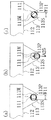
上述のように内枠12および前面枠セット14のいずれも閉じた状態あるいは後述の操作により前面枠セット14のみ開放した状態、即ち前面枠セット14の開閉状態を問わず内枠12を外枠11に対して閉じた状態で、図35に示すように、シリンダ錠62に鍵K1を挿入し、矢印A12で示すように圧縮コイルバネ62Sの付勢力に抗してシリンダ錠62を後方へ押し込みながら、図36に矢印A13で示すように、鍵K1を時計回り方向(図36では反時計回り方向)に回転させる。これにより、回転子67が後方へ押し込まれた位置で時計回り方向に回転し、これにともなって、係合突片67Eが係合片65の係合切欠65Rに係合して同図に矢印A14で示すように該係合切欠65Rを押し下げ、これにより図14ないし図20に示すように係合片65が引っ張りコイルバネ66の付勢力に抗して押し下げられる。こうして係合片65が押し下げられると、各フック65Hの鉤部65Eが受け金具から下方へ外れ、これにより、外枠11に対して内枠12が閉じた状態が解除されるので、内枠12の右側部を手前に引くようにして開放することができる。
B. Opening of the inner frame As described above, the inner frame 12 and the front frame set 14 are both closed, or only the front frame set 14 is opened by an operation described later, that is, regardless of whether the front frame set 14 is opened or closed. 35 is closed with respect to the outer frame 11, the key K1 is inserted into the cylinder lock 62 as shown in FIG. 35, and the cylinder lock 62 is moved backward against the urging force of the compression coil spring 62S as shown by an arrow A12. 36, the key K1 is rotated clockwise (counterclockwise in FIG. 36) as indicated by an arrow A13 in FIG. As a result, the rotor 67 rotates clockwise at the position where the rotor 67 is pushed rearward, and accordingly, the engaging protrusion 67E engages with the engaging notch 65R of the engaging piece 65, and the arrow in FIG. The engagement notch 65R is pushed down as indicated by A14, whereby the engagement piece 65 is pushed down against the urging force of the tension coil spring 66 as shown in FIGS. When the engagement piece 65 is pushed down in this way, the flange portion 65E of each hook 65H is released downward from the receiving metal fitting, thereby releasing the state in which the inner frame 12 is closed with respect to the outer frame 11, and thus the inner frame 12 It can be opened by pulling the right side of the front.

C.前面枠セットの左開き
上述のように内枠12および前面枠セット14のいずれも閉じた状態あるいは内枠12のみ開放した状態、即ち内枠12の開閉状態を問わず前面枠セット14を内枠12に対して閉じた状態で、図37に示すように、シリンダ錠62に鍵K1を挿入し、シリンダ錠62を押し込まずに圧縮コイルバネ62Sの付勢力により前方へ押し出された状態としたまま、図38に矢印A15で示すように、鍵K1を時計回り方向(図38では反時計回り方向)に回転させる。これにより、回転子67が後方へ押し込まれていない前方の位置で時計回り方向に回転し、これにともなって、係合突片67Eが右側スライダ68Rの掛止切欠682Rに係合して同図に矢印A16で示すように該掛止切欠682Rを押し下げ、これにより図26および図27に示すように右側スライダ68Rが押し下げられる。
C. Left opening of the front frame set As described above, the front frame set 14 is opened regardless of whether the inner frame 12 and the front frame set 14 are closed or only the inner frame 12 is opened, that is, whether the inner frame 12 is opened or closed. 37, with the key K1 inserted into the cylinder lock 62 and being pushed forward by the urging force of the compression coil spring 62S without being pushed in, as shown in FIG. As indicated by an arrow A15 in FIG. 38, the key K1 is rotated clockwise (in the counterclockwise direction in FIG. 38). As a result, the rotor 67 rotates in the clockwise direction at the front position where the rotor 67 is not pushed backward, and the engaging protrusion 67E engages with the latching cutout 682R of the right slider 68R. As shown by the arrow A16, the latching cutout 682R is pushed down, and thereby the right slider 68R is pushed down as shown in FIGS.

右側スライダ68Rが押し下げられると、フック片681Rに掛止している第1ワイア76Aおよび第2ワイア76Bがともに引き下げられる。第1ワイア76Aが引き下げられると、図43および図44に示すように、該第1ワイア76Aの先端に掛止している掛止片72Eが圧縮コイルバネ78の付勢力に抗して後方へ引かれ、これにより可動部材72が同図に矢印A17で示すように平面視時計回り方向に回動する。可動部材72がこうして回動すると、作動片72Fが基材73の固定作動片73Fから離れ拡開するように回動するが、この回動にともない、可動部材72における押圧片72Pの前端縁が回転軸82Sに突き当たり、同図に矢印A18で示すように圧縮コイルバネ86の付勢力に抗して該回転軸82Sを固定作動片73Fから離れるように左方へやや押しのける。これにより、回転軸82Sは基材73の軸嵌合切欠73Rから脱離し、一方、押圧片72Pの前端縁は、前述の通り可動部材72における軸嵌合切欠72Rの基端側(基部72B側)端の位置から、軸嵌合切欠72Rの円周方向よりも外側へ次第に拡がる形状となっているので、上述のように可動部材72が回動すると、作動片72Fの先端部と押圧片72Pの前端縁との間の間隙が、前方へ向けて開けるような体勢となり、したがって回転軸82Sが前方への移動を拘束されない状態(以下、「非拘束状態」とも称す)となる。他方、これと同時に、第2ワイア76Bが引き下げられることによって、右下軸支部70Bにおいても同様にして非拘束状態となる。   When the right slider 68R is pushed down, both the first wire 76A and the second wire 76B that are hooked on the hook piece 681R are pulled down. When the first wire 76A is pulled down, as shown in FIGS. 43 and 44, the latching piece 72E latched on the tip of the first wire 76A is pulled backward against the urging force of the compression coil spring 78. As a result, the movable member 72 rotates in the clockwise direction in plan view as indicated by an arrow A17 in FIG. When the movable member 72 rotates in this way, the operating piece 72F rotates so as to be separated from the fixed operating piece 73F of the base material 73 and expands. With this rotation, the front end edge of the pressing piece 72P in the movable member 72 is moved. It strikes the rotating shaft 82S and pushes the rotating shaft 82S slightly to the left so as to move away from the fixed operating piece 73F against the urging force of the compression coil spring 86 as shown by arrow A18 in FIG. Thereby, the rotating shaft 82S is detached from the shaft fitting notch 73R of the base material 73, while the front end edge of the pressing piece 72P is the base end side (base 72B side) of the shaft fitting notch 72R in the movable member 72 as described above. ) Since the shape gradually expands outward from the circumferential direction of the shaft fitting notch 72R from the end position, when the movable member 72 rotates as described above, the distal end portion of the operating piece 72F and the pressing piece 72P Thus, the gap between the front end edge and the front end edge of the rotary shaft 82S is such that it opens forward, so that the rotary shaft 82S is not restrained from moving forward (hereinafter also referred to as “unconstrained state”). On the other hand, at the same time, the second wire 76B is pulled down, so that the lower right shaft support portion 70B is similarly brought into an unconstrained state.

上述のようにして右上軸支部70Aおよび右下軸支部70Bにおいて非拘束状態となる一方で、左上軸支部70Cおよび左下軸支部70Dにおいては引き続き回転軸が軸支された体勢で拘束されているので、この状態で前面枠セット14の右側部を手前に引くようにすると、図21ないし図25に示すように左上軸支部70Cおよび左下軸支部70Dの回転軸まわりに前面枠セット14を開き戸状に左方へ開放すること(本明細書では「左開き」とも称す)が可能となる。同図に示すように、前面枠セット14を左方へ約90°回動させると、その左側面が内枠12に突き当たり、これ以上の回動は困難となる。即ち、前面枠セット14を左方へ約90°回動させた位置が左方への開放限界位置となっている。   As described above, the upper right shaft support portion 70A and the lower right shaft support portion 70B are in an unconstrained state, while the upper left shaft support portion 70C and the lower left shaft support portion 70D are continuously constrained by the posture in which the rotation shaft is supported. In this state, when the right side portion of the front frame set 14 is pulled toward the front, the front frame set 14 is opened like a door around the rotation axes of the upper left shaft support portion 70C and the lower left shaft support portion 70D as shown in FIGS. It is possible to open it to the left (also referred to as “left opening” in this specification). As shown in the figure, when the front frame set 14 is rotated about 90 ° to the left, the left side of the front frame set abuts against the inner frame 12 and it is difficult to rotate further. That is, the position where the front frame set 14 is rotated about 90 ° to the left is the open limit position to the left.

D.前面枠セットの右開き
上述のように内枠12および前面枠セット14のいずれも閉じた状態あるいは内枠12のみ開放した状態、即ち内枠12の開閉状態を問わず前面枠セット14を内枠12に対して閉じた状態で、図37に示すように、シリンダ錠62に鍵K1を挿入し、シリンダ錠62を押し込まずに圧縮コイルバネ62Sの付勢力により前方へ押し出された状態としたまま、図38に矢印A19で示すように、鍵K1を反時計回り方向(図38では時計回り方向)に回転させる。これにより、回転子67が後方へ押し込まれていない前方の位置で反時計回り方向に回転し、これにともなって、係合突片67Eが左側スライダ68Lの掛止切欠682Lに係合して同図に矢印A20で示すように該掛止切欠682Lを押し下げ、これにより図33および図34に示すように左側スライダ68Lが押し下げられる。
D. Opening the front frame set to the right As described above, the front frame set 14 is closed regardless of whether the inner frame 12 and the front frame set 14 are closed or only the inner frame 12 is opened, that is, whether the inner frame 12 is opened or closed. 37, with the key K1 inserted into the cylinder lock 62 and being pushed forward by the urging force of the compression coil spring 62S without being pushed in, as shown in FIG. As shown by an arrow A19 in FIG. 38, the key K1 is rotated counterclockwise (clockwise in FIG. 38). As a result, the rotor 67 rotates counterclockwise at the front position where the rotor 67 is not pushed backward, and the engagement protrusion 67E engages with the latching cutout 682L of the left slider 68L. The latching notch 682L is pushed down as shown by an arrow A20 in the figure, and as a result, the left slider 68L is pushed down as shown in FIGS.

左側スライダ68Lが押し下げられると、フック片681Lに掛止している第3ワイア76Cおよび第4ワイア76Dがともに引き下げられ、これにともない、上述の右上軸支部70Aおよび右下軸支部70Bが非拘束状態となる場合と同様にして、左上軸支部70Cおよび左下軸支部70Dが駆動されて非拘束状態となる。一方、右上軸支部70Aおよび右下軸支部70Bにおいては引き続き回転軸が軸支された体勢で拘束されているので、この状態で前面枠セット14の左側部を手前に引くようにすると、図28ないし図32に示すように右上軸支部70Aおよび右下軸支部70Bの回転軸まわりに前面枠セット14を開き戸状に右方へ開放すること(本明細書では「右開き」とも称す)が可能となる。同図に示すように、前面枠セット14を右方へ約90°回動させると、その右側面が内枠12に突き当たり、これ以上の回動は困難となる。即ち、前面枠セット14を右方へ約90°回動させた位置が右方への開放限界位置となっている。   When the left slider 68L is pushed down, the third wire 76C and the fourth wire 76D that are hooked on the hook piece 681L are both pulled down, and accordingly, the above-described right upper shaft support portion 70A and right lower shaft support portion 70B are unconstrained. In the same manner as in the state, the upper left shaft support portion 70C and the lower left shaft support portion 70D are driven to enter an unconstrained state. On the other hand, in the upper right shaft support portion 70A and the lower right shaft support portion 70B, the rotation shaft is still constrained by the posture in which the rotation shaft is supported. If the left side portion of the front frame set 14 is pulled toward this side in this state, FIG. 32. As shown in FIG. 32, it is possible to open the front frame set 14 to the right in the form of an open door around the rotation axes of the upper right shaft support portion 70A and the lower right shaft support portion 70B (also referred to as “right open” in this specification). It becomes. As shown in the figure, when the front frame set 14 is rotated about 90 ° to the right, the right side of the front frame set abuts against the inner frame 12 and it is difficult to rotate further. That is, the position where the front frame set 14 is rotated about 90 ° rightward is the rightward opening limit position.

以上のようにして、内枠12および前面枠セット14のいずれも、それぞれ外枠11および内枠12に対して押し込むようにして容易に閉じた状態に拘束することができ、一方、シリンダ錠62を押し込みながら鍵K1で回転させる、シリンダ錠62を押し込まずに鍵K1で時計回り方向に回転させる、ならびにシリンダ錠62を押し込まずに鍵K1で反時計回り方向に回転させる、という3通りの操作により、内枠12の開放、前面枠セットの左開きおよび前面枠セットの右開きという3通りの開放を容易に行うことができる。   As described above, both the inner frame 12 and the front frame set 14 can be easily restrained in a closed state by being pushed into the outer frame 11 and the inner frame 12, respectively. Rotate with key K1 while pushing down, rotate clockwise with key K1 without pushing cylinder lock 62, and rotate counterclockwise with key K1 without pushing cylinder lock 62 Thus, three ways of opening the inner frame 12, opening the front frame set to the left, and opening the front frame set to the right can be easily performed.

上記構成においては、内枠12の右上、右下、左上および左下の各隅部に、右上軸支部70A、右下軸支部70B、左上軸支部70Cおよび左下軸支部70Dがそれぞれ配設され、右上軸支部70Aおよび右下軸支部70Bを右側の一組とし、左上軸支部70Cおよび左下軸支部70Dを左側の一組とし、これらニ組を一対として、例えば右上軸支部70Aおよび右下軸支部70Bを選択的に非拘束状態とするといったように、左右一対のうちのいずれかの組ごとにまとめて(上下揃って)開放操作がなされるように構成されている。   In the above configuration, the upper right shaft support portion 70A, the lower right shaft support portion 70B, the upper left shaft support portion 70C, and the lower left shaft support portion 70D are disposed at the upper right, lower right, upper left and lower left corners of the inner frame 12, respectively. The shaft support portion 70A and the lower right shaft support portion 70B are one set on the right side, the upper left shaft support portion 70C and the lower left shaft support portion 70D are one set on the left side, and these two sets are paired, for example, the upper right shaft support portion 70A and the lower right shaft support portion 70B. In such a manner that the doors are selectively placed in an unconstrained state, the opening operation is performed collectively (up and down) for each pair of the left and right pairs.

また、上記構成によれば、前面枠セット14は、上記左右一対のうちのいずれかの組の軸支部を非拘束状態として開放した状態、即ち左開きまたは右開きとした状態で、軸支状態にある組の軸支部をさらに開放操作して非拘束状態とすることにより、前面枠セット14を内枠12から容易に取り外すこともできる。   Further, according to the above configuration, the front frame set 14 is in a state of being pivotally supported in a state in which any one of the pair of left and right shafts is opened in an unconstrained state, that is, in a state of being left-opened or right-opened. The front frame set 14 can also be easily removed from the inner frame 12 by further opening the set of shaft support portions into an unconstrained state.

ここで、前面枠セット14は、上述の通りシリンダ錠62を押し込まずに鍵K1で時計回り方向に回転させるか反時計回り方向に回転させるかによって、左開きとするかも右開きとするかも自在に選択することが可能となっている(本明細書においては、このようにいずれの方向へも自在に選択的に開放可能な方式を「二様開き」とも称す)が、本パチンコ機10においては、このような二様開きの構成に好適な構造で、前面枠セット14とパチンコ機10本体とを電気的に接続するようにしている。以下、この接続構造について説明する。   Here, the front frame set 14 may be left-opened or right-opened depending on whether it is rotated clockwise or counterclockwise with the key K1 without pushing the cylinder lock 62 as described above. (In this specification, a method that can be selectively opened in any direction in this way is also referred to as “two-way opening”), but in the pachinko machine 10 Is a structure suitable for such a double-open structure, and electrically connects the front frame set 14 and the main body of the pachinko machine 10. Hereinafter, this connection structure will be described.

図21ないし図24ならびに図28ないし図31に示すように、内枠12と前面枠セット14との間には、配線ガイド90が架設されている。配線ガイド90は、図50および図51に示すように、第1部材91と第2部材92とを連結して構成されている。   As shown in FIGS. 21 to 24 and FIGS. 28 to 31, a wiring guide 90 is installed between the inner frame 12 and the front frame set 14. As shown in FIGS. 50 and 51, the wiring guide 90 is configured by connecting a first member 91 and a second member 92.

第1部材91は、横方向に帯状に長く延び、幅方向が上下方向に一致するように起立した板状片よりなる本体91Bと、本体91Bの一方端から他方端近傍まで帯状に延び、幅方向が水平方向に一致するように横臥した体勢で本体91Bの上端縁に幅方向中央部で一体的に接合した板状片よりなるリブ91Rとを有し、全体として断面T字形状をなして横方向に延びる樹脂よりなる部材となっている。リブ91Rは、本体91Bの一方端よりやや内側の位置で本体91Bの幅方向(高さ方向)中央部に向かって直角に折れ曲がり、本体91Bを両側から挟むようにして下方へ延び、本体91Bの幅方向(高さ方向)中央部で本体91Bの一方端に向かって直角に折れ曲がって延びている。即ち、この折れ曲がった位置から本体91Bの先端まで、本体91Bとリブ91Rとが断面十字状に交差して延びる形状となっている。本体91Bおよびリブ91Rの先端には、軸受部91Cが一体的に形成されている。軸受部91Cは、本体91Bの幅(高さ)と同一の長さで上下に延びる円筒状体の本体91Bと反対側(図50では右側)の周面が長さ方向に帯状に欠落するようにして横断面C字形状をなして上下に延びる形状を有し、さらにその先端の開放部における両端縁が先端側へやや拡開しながらそれぞれ方形の片状に延出する構成となっている。また、本体91Bにおいて、上端縁に沿って延びるリブ91Rが上述のように本体91Bの幅方向(高さ方向)中央部に向かって直角に折れ曲がる部分の内側の位置から、リブ91Rの他方端近傍の位置まで、等間隔をおいて複数箇所(4箇所)に、それぞれリブ91Rの下面に沿って横長の長方形状に延びる形状をなして本体91Bを厚さ方向に貫通する掛止孔91Pが穿設されている。また、本体91Bの他方端部(軸受部91C形成側端部と反対側の端部)には、軸部91Sが一体的に形成されている。軸部91Sは、本体91Bの他方端部における上下端縁を上下両側から挟むようにして、上下に平行に並置された2枚の長円形状を有する板状体の一方端部が配置形成され、両板状体の他方端部の間に、回動軸(図示せず)が一体的に形成された構成となっている。   The first member 91 extends in a strip shape in the lateral direction and extends in a strip shape from a main body 91B made up of a plate-like piece standing so that the width direction coincides with the vertical direction, and from one end of the main body 91B to the vicinity of the other end. And a rib 91R made of a plate-like piece integrally joined to the upper end edge of the main body 91B in the width direction center portion in such a posture that the direction coincides with the horizontal direction, and has a T-shaped cross section as a whole. It is a member made of resin extending in the lateral direction. The rib 91R is bent at a right angle toward the center in the width direction (height direction) of the main body 91B at a position slightly inward from one end of the main body 91B, and extends downward so as to sandwich the main body 91B from both sides. (Height direction) It is bent at a right angle and extends toward one end of the main body 91B at the center. That is, the main body 91B and the ribs 91R extend from the bent position to the front end of the main body 91B so as to intersect with each other in a cross-shaped cross section. A bearing portion 91C is integrally formed at the ends of the main body 91B and the rib 91R. In the bearing portion 91C, the circumferential surface on the opposite side (right side in FIG. 50) of the cylindrical body extending vertically with the same length as the width (height) of the main body 91B is missing in a band shape in the length direction. And has a shape extending in the vertical direction with a C-shaped cross section, and further, both end edges of the open portion at the tip end are extended in the shape of a square piece while slightly expanding toward the tip end side. . Further, in the main body 91B, the rib 91R extending along the upper edge is bent at a right angle toward the central portion in the width direction (height direction) of the main body 91B as described above, and in the vicinity of the other end of the rib 91R. Latch holes 91P that penetrate the main body 91B in the thickness direction and have a shape extending in a horizontally long rectangular shape along the lower surface of the rib 91R at a plurality of positions (four locations) at equal intervals up to It is installed. A shaft portion 91S is integrally formed at the other end portion of the main body 91B (the end portion opposite to the bearing portion 91C forming side end portion). The shaft portion 91S is formed with one end portion of two oval plates arranged in parallel vertically so as to sandwich the upper and lower ends of the other end portion of the main body 91B from both the upper and lower sides. A rotation shaft (not shown) is integrally formed between the other end portions of the plate-like body.

第2部材92は、第1部材91と同一の寸法および形状を有し同一の樹脂よりなる部材となっており、第1部材91の場合と同様の本体92B、リブ92R、軸受部92C、掛止孔92Pおよび軸部92Sを有する構成となっている。このため、第2部材92についてこれ以上の説明は省略する。   The second member 92 has the same dimensions and shape as the first member 91 and is made of the same resin. The same as the first member 91, the main body 92B, the rib 92R, the bearing portion 92C, the hanging portion are the same. It has the structure which has the stop hole 92P and the axial part 92S. For this reason, further description of the second member 92 is omitted.

第1部材91の軸受部91Cには、第2部材92の軸部92Sの回動軸が圧入されて軸支され、これにより第1部材91と第2部材92とが上下方向の軸まわりに回動自在に連結されて配線ガイド90が構成されている。   The rotation shaft of the shaft portion 92S of the second member 92 is press-fitted into and supported by the bearing portion 91C of the first member 91, whereby the first member 91 and the second member 92 are rotated about the vertical axis. A wiring guide 90 is configured to be rotatably connected.

図22および図28に示すように、内枠12の前面における上端部中央には本体側軸受部12Cが、前面枠セット14の後面における上端部中央には前面扉側軸部部材14Sが、それぞれ配設されている。本体側軸受部12Cは、図50および図51に示すように、第1部材91の本体91Bの幅(高さ)と同一の厚さ(高さ)を有し、平面視先端が円弧状の略U字形状をなして内枠12の前面から前方へ突出するように形成されている。本体側軸受部12Cの先端部に、第1部材91の軸部91Sの回動軸(図示せず)が挿通されて回動自在に軸支されるようになっている。本体側軸受部12Cの上方には、本体側軸受部12Cの先端近傍の位置まで、横長の直方体形状をなして突出する開閉検出スイッチ12Sが突設されている。該開閉検出スイッチ12Sは、後方へ押圧すると内枠12内に没入し得るように構成されており、前面枠セット14の開閉を検出するスイッチとして機能するものとなっている。このように前面枠セット14の開閉を検出する開閉検出スイッチ12Sが内枠12の前面における上端部中央に配設されていることにより、前面枠セット14を左開きとした場合にも右開きとした場合にも同じタイミングでオンオフがなされるようになっている。前面扉側軸部部材14Sは、第2部材92の本体92Bの幅(高さ)と同一の間隔をおいて形成された上壁部と下壁部との間に回動軸(図示せず)が架設され、右側および左側には、前後方向に軸を有する円筒形状であって内部にネジ挿通孔を有するネジ挿通部がそれぞれ一体的に形成された構成を有する部材となっている。前面枠セット14の上端部には、図22および図28に示すように、右上軸支部70Aにすぐ隣接する位置から左上軸支部70Cにすぐ隣接する位置まで、上端縁に沿って溝状に横長に延びる形状をなして後面から凹入する凹入部14Nが形成されており、前面扉側軸部部材14Sは該凹入部14Nの中央部に嵌入され、ネジ挿通部でネジ固定されている。前面扉側軸部部材14Sの回動軸(図示せず)は、第2部材92の軸受部92Cに圧入され、これにより該軸受部92Cが前面扉側軸部部材14Sに回動自在に軸支されるようになっている。   As shown in FIGS. 22 and 28, the main body side bearing portion 12C is at the center of the upper end portion of the front surface of the inner frame 12, and the front door side shaft member 14S is at the center of the upper end portion of the rear surface of the front frame set 14, respectively. It is arranged. As shown in FIGS. 50 and 51, the main body side bearing portion 12C has the same thickness (height) as the width (height) of the main body 91B of the first member 91, and the tip in plan view has an arc shape. It is formed in a substantially U shape so as to protrude forward from the front surface of the inner frame 12. A rotation shaft (not shown) of the shaft portion 91S of the first member 91 is inserted into the distal end portion of the main body side bearing portion 12C so as to be pivotally supported. Above the main body side bearing portion 12C, an open / close detection switch 12S protrudes in a horizontally long rectangular parallelepiped shape to a position near the tip of the main body side bearing portion 12C. The opening / closing detection switch 12S is configured to be able to be immersed in the inner frame 12 when pressed backward, and functions as a switch for detecting opening / closing of the front frame set 14. As described above, the opening / closing detection switch 12S for detecting the opening / closing of the front frame set 14 is disposed at the center of the upper end portion of the front surface of the inner frame 12. In this case, it is turned on / off at the same timing. The front door side shaft member 14S has a rotation shaft (not shown) between an upper wall portion and a lower wall portion formed at the same interval as the width (height) of the main body 92B of the second member 92. ), And on the right side and the left side, a member having a configuration in which a screw insertion portion having a cylindrical shape having a shaft in the front-rear direction and having a screw insertion hole therein is integrally formed. As shown in FIG. 22 and FIG. 28, the front frame set 14 is horizontally long in a groove shape along the upper edge from the position immediately adjacent to the upper right pivot support 70A to the position immediately adjacent to the upper left pivot support 70C. The front door side shaft member 14S is fitted into the central portion of the recessed portion 14N and fixed with screws at the screw insertion portion. A rotation shaft (not shown) of the front door side shaft member 14S is press-fitted into the bearing portion 92C of the second member 92, so that the bearing portion 92C can pivot on the front door side shaft member 14S. It has come to be supported.

配線ガイド90の全長は、前面枠セット14が左方ないし右方への開放限界位置すなわち左方ないし右方へ約90°回動した位置にあるときの本体側軸受部12Cと前面扉側軸部部材14Sとの間の距離よりも、若干大きくなるように設定されている。これにより、図21ないし図24ならびに図28ないし図31に示すように、前面枠セット14が左方ないし右方への開放限界位置にあるとき、配線ガイド90が、その中央部すなわち第1部材91の軸受部91Cと第2部材92の軸部92Sとの連結部で若干だけ平面視略く字状に一方側(本実施形態では左側)へ角が突き出るように屈曲した体勢に保持されるようになっている。これによって、左方ないし右方への開放限界位置から前面枠セット14を閉じる際に、これにともなって配線ガイド90が確実かつスムーズに屈曲を進行させるようになっている。即ち、配線ガイド90がステーとなってつかえることにより前面枠セット14の回動を阻止するといった不具合が生じ難いようになっている。なおこの構成においては、前面枠セット14を右開きにするか左開きにするかを問わず配線ガイド90が常に大なり小なり一方側(本実施形態では左側)へ屈曲した体勢となるが、右側および左側のいずれの側へ屈曲させるようにしてもよい。   The total length of the wiring guide 90 is such that the front frame set 14 and the front door side shaft when the front frame set 14 is at the opening limit position to the left or right, that is, the position rotated about 90 ° to the left or right. It is set to be slightly larger than the distance between the member 14S. Accordingly, as shown in FIGS. 21 to 24 and FIGS. 28 to 31, when the front frame set 14 is at the open limit position to the left or right, the wiring guide 90 has its center, that is, the first member. The connecting portion between the bearing portion 91 </ b> C of 91 and the shaft portion 92 </ b> S of the second member 92 is held in a posture that is bent so that a corner protrudes slightly toward one side (left side in the present embodiment) in a substantially square shape in plan view. It is like that. As a result, when the front frame set 14 is closed from the left or right open limit position, the wiring guide 90 advances the bending reliably and smoothly. That is, since the wiring guide 90 can be used as a stay, the problem of preventing the rotation of the front frame set 14 is unlikely to occur. In this configuration, regardless of whether the front frame set 14 is opened to the right or left, the wiring guide 90 is always larger or smaller, and the posture is bent to one side (the left side in the present embodiment). It may be bent to either the right side or the left side.

前面枠セット14をさらに閉じていくと、これにともなって配線ガイド90もさらに屈曲していき、前面枠セット14を最後まで閉じると、配線ガイド90は二つ折りに折り畳まれた体勢となって、内枠12と前面枠セット14との間、具体的には前面枠セット14の凹入部14N内に収納される。   When the front frame set 14 is further closed, the wiring guide 90 is further bent along with this, and when the front frame set 14 is closed to the end, the wiring guide 90 is in a folded state. It is housed between the inner frame 12 and the front frame set 14, specifically, in the recessed portion 14 </ b> N of the front frame set 14.

配線ガイド90には、図52に示すように、前面枠セット14とパチンコ機10本体とを電気的に接続するハーネス93が保持される。即ち、複数本のハーネス93がハーネス留具94により束ねられながら配線ガイド90に固定される。ハーネス留具94は、配線ガイド90の第1および第2部材91、92における掛止孔91P、92Pの幅より僅かに小さい長辺とこの長辺より小さい短辺とを有する長方形状の底片94Bを有し、該底片94Bの両長辺が上方に延出して平行な2つの延出片が形成され、このうちの一方の延出片が外側(図52では右側)へ直角に折れ曲がって延出して下側の掛止片94Eが形成され、他方の延出片が、下側の掛止片94Eよりもさらに上方まで延出してから内側へ折れ曲がって下側の掛止片94Eと同方向に同一位置までほぼ平行に延出して上側の掛止片94Eが形成されるように、全体として樹脂により一体的に成形された部材となっている。上下の掛止片94Eの間隔は、掛止孔91P、92Pの上下幅(高さ)より僅かに大きくなっている。また、上下の掛止片94Eの先端部には、先端からそれぞれ上側および下側へ次第に厚みが増大するよう斜面をなし、先端から一定距離の地点で元の掛止片94Eの厚みに戻るように垂直面をなして、全体として断面略直角三角形状に上下に突出する爪部が形成されている。ハーネス留具94には、上下の掛止片94Eの間から複数本のハーネス93が内部に挿入され、この状態で上下の掛止片94Eが配線ガイド90の掛止孔91P、92Pに圧入される。上下の掛止片94Eが互いにやや寄り合うように弾性変形しながら掛止孔91P、92Pに進入していき、最後まで圧入されると、上下の掛止片94Eの爪部がそれぞれ掛止孔91P、92Pの上端縁および下端縁に掛止し、これによりハーネス留具94が掛止孔91P、92Pに固定される。   As shown in FIG. 52, the wiring guide 90 holds a harness 93 that electrically connects the front frame set 14 and the main body of the pachinko machine 10. That is, a plurality of harnesses 93 are fixed to the wiring guide 90 while being bundled by the harness fastener 94. The harness fastener 94 is a rectangular bottom piece 94B having a long side slightly smaller than the width of the retaining holes 91P and 92P in the first and second members 91 and 92 of the wiring guide 90 and a short side smaller than the long side. The two long sides of the bottom piece 94B extend upward to form two parallel extended pieces, and one of the extended pieces bends to the outside (right side in FIG. 52) at a right angle and extends. The lower hooking piece 94E is formed, and the other extending piece extends further upward than the lower hooking piece 94E and then bends inward to be in the same direction as the lower hooking piece 94E. As a whole, it is a member integrally formed of resin so that the upper retaining piece 94E is formed so as to extend substantially parallel to the same position. The interval between the upper and lower hooking pieces 94E is slightly larger than the vertical width (height) of the hooking holes 91P and 92P. In addition, the tip portions of the upper and lower latch pieces 94E are inclined so that the thickness gradually increases from the tip toward the upper side and the lower side, respectively, so that the thickness of the original latch piece 94E is restored at a certain distance from the tip. A claw portion is formed which has a vertical surface and protrudes up and down in a substantially right triangle shape in cross section as a whole. A plurality of harnesses 93 are inserted into the harness retainer 94 from between the upper and lower hooking pieces 94E. In this state, the upper and lower hooking pieces 94E are press-fitted into the hooking holes 91P and 92P of the wiring guide 90. The The upper and lower hooking pieces 94E enter the hooking holes 91P and 92P while being elastically deformed so that they slightly approach each other. When the upper and lower hooking pieces 94E are press-fitted to the end, the claw portions of the upper and lower hooking pieces 94E are respectively inserted into the hooking holes. The harness fasteners 94 are hooked on the upper and lower edges of 91P and 92P, whereby the harness fastener 94 is fixed to the hooking holes 91P and 92P.

ハーネス93の一方側は、内枠12の上端部中央を経て、パチンコ機10本体に配置されたサブ制御基板に接続され、ハーネス93の他方側は、前面枠セット14の上端部中央を経て、前記各種ランプ等の発光手段のような電気部品に接続される。ここで、本パチンコ機10においては、上述の通り前面枠セット14が内枠12に対して二様開き可能に取り付けられているため、仮に右側および左側のいずれか一方側の端部で接続を行うと、この接続された一方側の軸支部を非拘束状態として前面枠セット14を開放する場合には、内枠12側の接続部と前面枠セット14側の接続部とが最大限に離隔することとなってその間の配線の長さも最大となり、そのぶん配線の収納も煩瑣で多くのスペースを要するものとなるとともに、前面枠セット14の開放状態において配線が邪魔ともなりやすい。そこで、本パチンコ機10においては、上述の通り、内枠12の左右方向中央と前面枠セット14の左右方向中央とを介して内枠12と前面枠セット14とを電気的に接続するようにしているので、配線すなわちハーネス93が、長さも最小限に抑えられて収納しやすく邪魔となり難いようになっている。   One side of the harness 93 is connected to the sub-control board disposed in the main body of the pachinko machine 10 through the center of the upper end portion of the inner frame 12, and the other side of the harness 93 is connected to the center of the upper end portion of the front frame set 14, It is connected to electrical components such as light emitting means such as the various lamps. Here, in this pachinko machine 10, since the front frame set 14 is attached to the inner frame 12 so that it can be opened in two ways as described above, the connection is temporarily made at the end on either the right side or the left side. When this is done, when the front frame set 14 is opened with the connected one-side shaft support portion in an unconstrained state, the connection portion on the inner frame 12 side and the connection portion on the front frame set 14 side are separated as much as possible. As a result, the length of the wiring in the meantime is maximized, the storage of the wiring is troublesome and a lot of space is required, and the wiring tends to become an obstacle in the open state of the front frame set 14. Therefore, in the pachinko machine 10, as described above, the inner frame 12 and the front frame set 14 are electrically connected via the center in the left-right direction of the inner frame 12 and the center in the left-right direction of the front frame set 14. Therefore, the wiring, that is, the harness 93 is minimized in length and is easy to be stored and is not easily disturbed.

さらに、本パチンコ機10においては、ハーネス93が案内部材である配線ガイド90により保持されながら案内される構成となっている。上述の通り、内枠12と前面枠セット14との間に架設されるハーネス93の長さが最小限に抑えられているのであるが、仮にこのハーネス93が他の部材を用いることなくそのまま単独で架設されると、前面枠セット14を閉じた状態ではハーネス93の体勢が一定せず、パチンコ機10の外部にはみ出したり、あるいは、近傍に何らかの突出構造があればこれに引っ掛かったりして、該ハーネス93自体が損傷しやすくなり、外観も損なわれることとなりやすい。また、前面枠セット14を開放した状態でも、ハーネス93がそのまま単独で架設されていると、なんらかの外力が加わった場合にこれを直接に受けることとなり、やはり損傷しやすいこととなる。これに対し、上記のようにハーネス93を配線ガイド90により保持しながら案内するようにすることにより、前面枠セット14を閉じた状態において、ハーネス93を外部にはみ出したり引っ掛かったりすることなく適正な体勢で収納することができる。また、前面枠セット14を開放した状態でも、ハーネス93が配線ガイド90により防護されて外力による影響が緩和される。   Further, in the present pachinko machine 10, the harness 93 is guided while being held by the wiring guide 90 which is a guide member. As described above, the length of the harness 93 installed between the inner frame 12 and the front frame set 14 is minimized, but the harness 93 is used as it is without using other members. When the front frame set 14 is closed, the posture of the harness 93 is not constant and protrudes outside the pachinko machine 10, or if there is any protruding structure in the vicinity, The harness 93 itself is easily damaged and the appearance is liable to be damaged. Even when the front frame set 14 is opened, if the harness 93 is erected as it is, it will be directly received when any external force is applied, and it will be easily damaged. On the other hand, as described above, the harness 93 is guided while being held by the wiring guide 90, so that the harness 93 does not protrude or get caught outside when the front frame set 14 is closed. Can be stored in a posture. Even when the front frame set 14 is opened, the harness 93 is protected by the wiring guide 90 and the influence of external force is alleviated.

(作用)
本パチンコ機10は、本体部材(遊技球が流下する遊技領域が前面に形成された遊技盤30)と、この本体部材の前面(遊技盤30の盤面)側を覆う前面扉である前面枠セット14と、この前面枠セット14を開放操作するためのシリンダ錠62を用いた鍵操作機構とを備える構成において、前記前面枠セット14が、対向する一対の端縁部である右側端縁部および左側端縁部でそれぞれ右上および右下軸支部70A、70Bならびに左上および左下軸支部70C、70Dからなる軸支機構により、遊技機本体側の部材である内枠12に着脱可能に軸支され、上記シリンダ錠62を用いた鍵操作機構を操作することにより、上記一対の軸支機構(即ち右上および右下軸支部70A、70Bと左上および左下軸支部70C、70Dとの一対)における軸支状態のうちのいずれか一方を軸として開閉し得る構成となっている。
(Function)
The pachinko machine 10 includes a main body member (a game board 30 on which a game area where a game ball flows down is formed on the front surface) and a front frame set which is a front door that covers the front surface (the board surface of the game board 30) of the main body member. 14 and a key operation mechanism using a cylinder lock 62 for opening the front frame set 14, the front frame set 14 is a pair of opposed right end edges and At the left edge portion, the shaft support mechanism comprising the upper right and lower right shaft support portions 70A and 70B and the upper left and lower left shaft support portions 70C and 70D is removably supported by the inner frame 12 which is a member on the gaming machine body side, By operating the key operation mechanism using the cylinder lock 62, the pair of shaft support mechanisms (that is, the pair of the upper right and lower right shaft support portions 70A and 70B and the upper left and lower left shaft support portions 70C and 70D) Kicking has a structure capable of opening and closing either one of the shaft supporting condition as an axis.

上記構成によれば、前面枠セット14を一対の端縁部すなわち左右両端縁部でそれぞれ軸支機構により内枠12に軸支することによって、前面枠セット14を閉じた状態(閉状態)で拘束することができる。一方、この閉状態でシリンダ錠62を用いた鍵操作機構を操作(開放操作)して一対の軸支機構における軸支状態のうちのいずれか一方を軸として開閉することによって、前面枠セット14を回動させて開き戸式に開放することができる。即ち、前面枠セット14における一対の端縁部すなわち左右両端縁部のうち、いずれの端縁部を固定端(軸支側端)としいずれの端縁部を自由端とするかを自在に選択して切替えることができるので、前面枠セット14をその一対の端縁部のうちのいずれの端縁部側へも自在に選択的に開放すること、即ち前面枠セット14の二様開きが可能となっている。   According to the above configuration, the front frame set 14 is closed (closed state) by pivotally supporting the front frame set 14 on the inner frame 12 by the pivotal support mechanism at a pair of edge portions, that is, both left and right edge portions. Can be restrained. On the other hand, by operating (opening) the key operation mechanism using the cylinder lock 62 in this closed state, the front frame set 14 is opened and closed with one of the shaft support states of the pair of shaft support mechanisms as an axis. Can be opened to open the door. That is, of the pair of edge portions in the front frame set 14, that is, the left and right edge portions, it is possible to freely select which edge portion is a fixed end (shaft support side end) and which edge portion is a free end. The front frame set 14 can be selectively opened to any one of the pair of end edges, that is, the front frame set 14 can be opened in two ways. It has become.

したがって、盤面に対する各種作業を行う際には、作業を行う部位から比較的に離れた端縁部側へ前面枠セット14を開放することにより、該前面枠セット14が作業の邪魔とならないようにすることができる。   Therefore, when performing various operations on the board surface, the front frame set 14 is opened to the edge portion side relatively away from the operation site so that the front frame set 14 does not interfere with the operation. can do.

また、両隣の遊技機のうち、例えば遊技中でない等の理由により比較的に邪魔になり難くなっている一方側へ選択的に前面枠セット14を開放することにより、該前面枠セット14が他方側に隣接する遊技機の遊技に対して邪魔とならないようにすることもできる。   Moreover, by selectively opening the front frame set 14 to one side that is relatively difficult to get in the way, for example, because the game machine is not playing, the front frame set 14 is It is also possible to prevent the game machine adjacent to the side from getting in the way.

また、上記軸支機構が、遊技機本体側の部材である内枠12に配設された一対の作動片72F、73Fと、前面扉である前面枠セット14に配設された回転軸82Sとを有して構成され、上記一対の作動片72F、73Fが、開閉可能に構成されて付勢手段である圧縮コイルバネ78で付勢されることにより通常は合わさって閉じた体勢に保持され、両作動片72F、73Fにはそれぞれ軸嵌合切欠72R、73Rが設けられ、両作動片72F、73Fが閉じるのにともない両軸嵌合切欠72R、73Rが一体となって軸挿通孔が形成されるように構成されているので、両作動片72F、73Fを開閉させて該軸挿通孔に上記回転軸82Sを挿通することにより、容易かつ確実に前面枠セット14を内枠12に着脱可能に軸支することができるようになっている。   The shaft support mechanism includes a pair of operating pieces 72F and 73F disposed on the inner frame 12 which is a member on the gaming machine main body side, and a rotating shaft 82S disposed on the front frame set 14 which is a front door. The pair of actuating pieces 72F and 73F are configured to be openable and closable, and are normally held together by being biased by a compression coil spring 78 that is a biasing means. The operating pieces 72F and 73F are provided with shaft fitting notches 72R and 73R, respectively, and the shaft inserting notches 72R and 73R are integrated to form a shaft insertion hole as the operating pieces 72F and 73F are closed. Therefore, the front frame set 14 can be attached to and detached from the inner frame 12 easily and reliably by opening and closing both the operating pieces 72F and 73F and inserting the rotating shaft 82S into the shaft insertion hole. Can support It has become way.

また、上記鍵操作機構が、鍵K1を挿入して一方に回転させると、上記一対の軸支機構における軸支状態のうちのいずれか一方を解除することができ、鍵K1を挿入して他方に回転させると、上記一対の軸支機構における軸支状態のうちの他方を解除することができるように構成されているので、鍵K1の操作により前面枠セット14の二様開きを簡便かつ確実に行うことができるようになっている。   Further, when the key operating mechanism inserts the key K1 and rotates it to one side, any one of the shaft support states in the pair of shaft support mechanisms can be released, and the key K1 is inserted and the other Since the other of the shaft support states of the pair of shaft support mechanisms can be released by rotating the front frame set 14, the front frame set 14 can be easily and reliably opened by operating the key K1. To be able to do that.

また、上記鍵K1の回転による動力が、線状部材である第1ないし第4ワイア76A、76B、76C、76Dを介して伝達されることにより、上記一対の軸支機構すなわち右上および右下軸支部70A、70Bと左上および左下軸支部70C、70Dとの一対がそれぞれ駆動されるようになっているので、鍵K1の挿入部すなわちシリンダ錠62から離隔した駆動位置である右上、右下、左上および左下軸支部70A、70B、70C、70Dのそれぞれへ、簡潔な構成により効果的に動力が伝達されるようになっている。   Further, the power generated by the rotation of the key K1 is transmitted through the first to fourth wires 76A, 76B, 76C, and 76D, which are linear members, so that the pair of shaft support mechanisms, that is, the upper right and lower right shafts. Since a pair of the support portions 70A, 70B and the upper left and lower left shaft support portions 70C, 70D are driven, the upper right, lower right, upper left, which are drive positions separated from the insertion portion of the key K1, that is, the cylinder lock 62 Power is effectively transmitted to each of the lower left shaft support portions 70A, 70B, 70C, and 70D with a simple configuration.

また、上記前面扉である前面枠セット14が軸支される遊技機本体側の部材が内枠12となっており、さらに該内枠12が、遊技機本体側の別の部材である外枠11に軸支されており、上記鍵操作機構が、鍵K1を挿入して押し込みながら回転させると、上記外枠11に対して内枠12が閉じて拘束された状態が解除されるように構成されているので、上記前面枠セット14の二様開きに内枠12の開放もあわせた3通りの開放操作を鍵K1の操作により簡便かつ確実に行うことができるようになっている。   Further, a member on the gaming machine main body side on which the front frame set 14 that is the front door is pivotally supported is an inner frame 12, and the inner frame 12 is an outer frame that is another member on the gaming machine main body side. 11 and is configured such that when the key operating mechanism rotates while inserting and pushing the key K1, the state in which the inner frame 12 is closed and restrained with respect to the outer frame 11 is released. Therefore, three types of opening operations including the two-way opening of the front frame set 14 and the opening of the inner frame 12 can be easily and reliably performed by operating the key K1.

また、本パチンコ機10は、本体部材(遊技球が流下する遊技領域が前面に形成された遊技盤30)と、この本体部材の前面(遊技盤30の盤面)側を覆う前面扉である前面枠セット14と、この前面枠セット14を開放操作するためのシリンダ錠62を用いた操作機構とを備える構成において、前記前面枠セット14が、対向する一対の端縁部である右側端縁部および左側端縁部でそれぞれ右上および右下軸支部70A、70Bならびに左上および左下軸支部70C、70Dからなる軸支機構により、遊技機本体側の部材である内枠12に着脱可能に軸支され、上記シリンダ錠62を用いた操作機構を操作することにより、上記一対の軸支機構(即ち右上および右下軸支部70A、70Bと左上および左下軸支部70C、70Dとの一対)における軸支状態のうちのいずれか一方を軸として開閉可能に構成され、上記対向する一対の端縁部の間における実質的に中央の位置を介して、上記前面枠セット14と上記内枠12とが電気的に接続された構成となっている。   Further, the pachinko machine 10 is a front surface that is a front door that covers a main body member (a game board 30 on which a game area where a game ball flows down is formed on the front face) and a front face of the main body member (the board face of the game board 30). In a configuration including a frame set 14 and an operation mechanism using a cylinder lock 62 for opening the front frame set 14, the front frame set 14 is a pair of opposed edge portions on the right edge. The left and right end edges are detachably supported by the inner frame 12 which is a member on the gaming machine main body by the shaft support mechanism including the upper right and lower right shaft support portions 70A and 70B and the upper left and lower left shaft support portions 70C and 70D. By operating the operation mechanism using the cylinder lock 62, the pair of shaft support mechanisms (that is, a pair of the upper right and lower right shaft support portions 70A and 70B and the upper left and lower left shaft support portions 70C and 70D). The front frame set 14 and the inner frame 12 are configured to be openable and closable with any one of the pivotal support states as an axis, and through a substantially central position between the pair of opposed end edges. And are electrically connected.

上記構成によれば、前面枠セット14を一対の端縁部すなわち左右両端縁部でそれぞれ軸支機構により内枠12に軸支することによって、前面枠セット14を閉じた状態(閉状態)で拘束することができる。一方、この閉状態でシリンダ錠62を用いた操作機構を操作(開放操作)して一対の軸支機構における軸支状態のうちのいずれか一方を軸として開閉することによって、前面枠セット14を回動させて開き戸式に開放することができる。即ち、前面枠セット14における一対の端縁部すなわち左右両端縁部のうち、いずれの端縁部を固定端(軸支側端)としいずれの端縁部を自由端とするかを自在に選択して切替えることができるので、前面枠セット14をその一対の端縁部のうちのいずれの端縁部側へも自在に選択的に開放すること、即ち前面枠セット14の二様開きが可能となっている。   According to the above configuration, the front frame set 14 is closed (closed state) by pivotally supporting the front frame set 14 on the inner frame 12 by the pivotal support mechanism at a pair of edge portions, that is, both left and right edge portions. Can be restrained. On the other hand, by operating (opening) the operation mechanism using the cylinder lock 62 in this closed state, the front frame set 14 is opened and closed with one of the shaft support states of the pair of shaft support mechanisms as an axis. It can be rotated and opened in a hinged door manner. That is, of the pair of edge portions in the front frame set 14, that is, the left and right edge portions, it is possible to freely select which edge portion is a fixed end (shaft support side end) and which edge portion is a free end. The front frame set 14 can be selectively opened to any one of the pair of end edges, that is, the front frame set 14 can be opened in two ways. It has become.

したがって、盤面に対する各種作業を行う際には、作業を行う部位から比較的に離れた端縁部側へ前面枠セット14を開放することにより、該前面枠セット14が作業の邪魔とならないようにすることができる。   Therefore, when performing various operations on the board surface, the front frame set 14 is opened to the edge portion side relatively away from the operation site so that the front frame set 14 does not interfere with the operation. can do.

また、両隣の遊技機のうち、例えば遊技中でない等の理由により比較的に邪魔になり難くなっている一方側へ選択的に前面枠セット14を開放することにより、該前面枠セット14が他方側に隣接する遊技機の遊技に対して邪魔とならないようにすることもできる。   Moreover, by selectively opening the front frame set 14 to one side that is relatively difficult to get in the way, for example, because the game machine is not playing, the front frame set 14 is It is also possible to prevent the game machine adjacent to the side from getting in the way.

ところで、前面枠セット14には、前記各種ランプ等の発光手段のような電気部品が配設されているので、前面枠セット14とパチンコ機10本体とを電気的に接続することが必要であるが、従来の遊技機では、前面扉が常に一方側縁で軸支された構造となっていたため、この軸支された側で配線を行うなどして前面扉と遊技機本体とを電気的に接続するようにすればよかった。ところが、本パチンコ機10においては上述のように前面枠セット14が二様開き可能に構成されており、いずれの側でも前面枠セット14がパチンコ機10本体から分離し得るようになっているため接続は行い難くなっている。   By the way, since the front frame set 14 is provided with electrical components such as light emitting means such as the various lamps, it is necessary to electrically connect the front frame set 14 and the main body of the pachinko machine 10. However, in the conventional gaming machine, since the front door is always pivotally supported on one side edge, the front door and the gaming machine main body are electrically connected by wiring on this pivotally supported side. I should have connected. However, in this pachinko machine 10, the front frame set 14 can be opened in two ways as described above, and the front frame set 14 can be separated from the main body of the pachinko machine 10 on either side. Connection is difficult to make.

そこで、本パチンコ機10においては、上記一対の端縁部すなわち右側端縁部と左側端縁部との間における中央の位置を介して前面枠セット14とパチンコ機10本体側の内枠12とを電気的に接続する構造となっている。これにより、前面枠セット14が二様開き可能に構成されていながら、前面枠セット14とパチンコ機10本体との電気的な接続が容易かつ確実になされている。   Therefore, in the pachinko machine 10, the front frame set 14 and the inner frame 12 on the main body side of the pachinko machine 10 are arranged via the center position between the pair of edge portions, that is, the right edge portion and the left edge portion. Are electrically connected. Thereby, the front frame set 14 and the pachinko machine 10 main body can be easily and reliably connected to each other while the front frame set 14 can be opened in two ways.

また、上記前面枠セット14と上記内枠12とが配線であるハーネス93により電気的に接続され、該ハーネス93が、案内部材である配線ガイド90により保持されながら案内される構成となっているので、前面枠セット14を閉じた状態において、ハーネス93が外部にはみ出したり引っ掛かったりすることなく適正な体勢で収納されるようになっており、また一方、前面枠セット14を開放した状態でも、ハーネス93が配線ガイド90により防護されて外力による影響が緩和されるようになっている。   Further, the front frame set 14 and the inner frame 12 are electrically connected by a harness 93 that is a wiring, and the harness 93 is guided while being held by a wiring guide 90 that is a guide member. Therefore, in a state where the front frame set 14 is closed, the harness 93 is stored in a proper posture without protruding or being caught outside, and on the other hand, even when the front frame set 14 is opened, The harness 93 is protected by the wiring guide 90 so that the influence of external force is mitigated.

また、上記配線ガイド90が折り畳み自在に構成されているので、前面枠セット14を閉じるのにともなって配線ガイド90が折り畳まれた体勢で内枠12と前面枠セット14との間にコンパクトに収納されることができるようになっている。   In addition, since the wiring guide 90 is configured to be foldable, the wiring guide 90 is folded between the inner frame 12 and the front frame set 14 so that the wiring guide 90 is folded when the front frame set 14 is closed. Be able to be.

また、上記前面枠セット14に、折り畳まれた体勢の配線ガイド90を収納可能な凹入部14Nが形成されているので、配線ガイド90がよりコンパクトに収納されるようになっている。   Further, the front frame set 14 is formed with a recessed portion 14N that can accommodate the folded-up wiring guide 90, so that the wiring guide 90 can be stored more compactly.

(変更態様)
上記実施形態には、例えば以下に示すように種々の変更を加えることが可能である。
(Modification)
Various modifications can be made to the above embodiment, for example, as shown below.

(1)上記実施形態においては、開閉可能に構成された一対の作動片72F、73Fにそれぞれ軸嵌合切欠72R、73Rが設けられ、両作動片72F、73Fが閉じるのにともない両軸嵌合切欠72R、73Rが一体となって軸挿通孔が形成され、該軸挿通孔に回転軸82Sが挿通されるようにして軸支機構が構成されていたが、軸支機構としてはこのようなものに限定されず、例えば図53に示すように、開閉可能に構成された係合リング部95に回転軸96が着脱可能に軸支される構成としたもの等も可能である。なお、図53に示す変更態様に係る軸支機構は、遊技機における左右両側端部で同様に構成されており、このため図53では遊技機における右側端部のみを図示し、左側端部は図示省略している。 (1) In the above-described embodiment, the pair of operating pieces 72F and 73F configured to be openable and closable are provided with the shaft fitting cutouts 72R and 73R, respectively, and the both shaft fittings 72F and 73F are closed as the both operating pieces 72F and 73F are closed. The shaft support mechanism is configured such that the notches 72R and 73R are integrated to form a shaft insertion hole, and the rotation shaft 82S is inserted into the shaft insertion hole. For example, as shown in FIG. 53, a configuration in which the rotary shaft 96 is detachably supported by an engagement ring portion 95 configured to be opened and closed is also possible. Note that the shaft support mechanism according to the modification shown in FIG. 53 is similarly configured at the left and right side end portions of the gaming machine. Therefore, in FIG. 53, only the right end portion of the gaming machine is illustrated, and the left end portion is illustrated. The illustration is omitted.

図53に示す変更態様に係る軸支機構においては、遊技機本体側部材97の左右両側に、前方へ平面視概略台形状に突出する基部95Bがそれぞれ配設され、前面扉(図示せず)の左右両側に、上下に延びる回転軸96がそれぞれ配設されている。上記基部95Bの先端面には、後方へ平面視半円状に凹入する凹入部95Rが形成されている。基部95Bの内部には、凹入部95Rの後方に、該凹入部95Rの周面に沿って周方向に移動可能に平面視概略半円状の可動リング片95Mが収容され得るようになっており、凹入部95Rの一方側(図53では左側)から前方へ出入し得るように構成され、通常は付勢手段(図示せず)により同図に矢印A21で示すように前方へ出る方向(図53では反時計回り方向)に180°近く回動して、凹入部95Rとともに平面視略円形の軸挿通孔をなす閉止体勢に保持されるようになっている。こうして閉止体勢にある可動リング片95Mは、シリンダ錠での鍵の操作による動力が駆動機構(図示せず)を介して伝達されることにより、同図に矢印A22で示すように基部95Bの内部に収容される方向(図53では時計回り方向)に180°近く回動し、これにより凹入部95Rの前方が開放されて、回転軸96の着脱が可能な体勢となるようになっている。   In the axial support mechanism according to the modified mode shown in FIG. 53, base portions 95B that project in a generally trapezoidal shape in plan view are disposed on the left and right sides of the gaming machine main body side member 97, respectively, and a front door (not shown). Rotating shafts 96 extending in the vertical direction are respectively disposed on both the left and right sides. A recessed portion 95R is formed on the distal end surface of the base portion 95B. The recessed portion 95R is recessed backward in a semicircular shape in plan view. Inside the base portion 95B, a movable ring piece 95M having a substantially semicircular shape in plan view can be accommodated behind the recessed portion 95R so as to be movable in the circumferential direction along the circumferential surface of the recessed portion 95R. It is configured to be able to enter / exit forward from one side (left side in FIG. 53) of the recessed portion 95R, and is normally forwarded by an urging means (not shown) as indicated by an arrow A21 in FIG. 53, it is rotated in the counterclockwise direction) by nearly 180 °, and is held in a closed posture that forms a shaft insertion hole having a substantially circular shape in plan view together with the recessed portion 95R. In this way, the movable ring piece 95M in the closed posture is transmitted to the inside of the base portion 95B as shown by an arrow A22 in the figure by transmitting the power generated by the key operation of the cylinder lock through a drive mechanism (not shown). Is rotated by nearly 180 ° in the direction in which the rotary shaft 96 is accommodated (clockwise in FIG. 53), thereby opening the front of the recessed portion 95R so that the rotary shaft 96 can be attached and detached.

本変更態様に係る軸支機構によっても、上記実施形態の場合と同様に、前面扉を二様開き可能に構成することができる。ただし、上記実施形態の場合には回転軸82Sを押し込むようにするだけで軸挿通孔に挿通させることができるのに対し、本変更態様の場合には閉止体勢にある可動リング片95Mを開放させてからでないと回転軸96を軸挿通孔に挿通させることができない。また、本変更態様の場合にはリング片95Mの回動範囲が大きく、駆動機構もやや複雑となるきらいがある。これらの点からは、上記実施形態に係る軸支機構のほうが有利である。   Also with the shaft support mechanism according to this modification, the front door can be configured to be able to open in two ways, as in the case of the above embodiment. However, in the case of the above-described embodiment, the rotary shaft 82S can be inserted into the shaft insertion hole simply by pushing in, whereas in the case of this modification, the movable ring piece 95M in the closed posture is opened. The rotating shaft 96 cannot be inserted through the shaft insertion hole unless it is later. Further, in the case of this change mode, there is a tendency that the rotation range of the ring piece 95M is large and the drive mechanism is somewhat complicated. From these points, the shaft support mechanism according to the embodiment is more advantageous.

(2)また、軸支機構として、例えば図54に示すように、前面扉が閉じた体勢にあるときのみ回転軸111が前方へ脱離し得るように軸支される構成としたもの等も可能である。なお、図54に示す変更態様に係る軸支機構は、遊技機における左右両側端部で左右対称に構成されており、このため図54では遊技機における右側端部のみを図示し、左側端部は図示省略している。 (2) Further, as the shaft support mechanism, for example, as shown in FIG. 54, a structure in which the rotary shaft 111 is supported so that it can be detached forward only when the front door is in a closed posture is possible. It is. Note that the shaft support mechanism according to the modification shown in FIG. 54 is configured to be bilaterally symmetric at the left and right side ends of the gaming machine. Therefore, only the right side edge of the gaming machine is shown in FIG. Is not shown.

図54に示す変更態様に係る軸支機構においては、遊技機本体側部材112の左右両側に、前方へ突出する軸挿通部113がそれぞれ配設され、前面扉(図示せず)の左右両側に、上下に延びる回転軸111がそれぞれ配設されている。該軸挿通部113の先端部には、平面視円孔状に上下に貫通する軸挿通孔113Pが穿設され、該軸挿通孔113Pの前側の周部には、該軸挿通孔113Pの径よりも小さい幅W11のスリット113Sが形成されている。これにより、軸挿通部113の先端部が、スリット113Sを通して軸挿通孔113Pが前方の空間と連通する平面視略C字状の形状となっている。回転軸111は、上記軸挿通孔113Pの径よりも僅かに小さい径を有する金属製の丸棒状の軸となっているが、図55に示すように、軸挿通部113に対応する高さ位置に、該軸挿通部113の厚さより若干大きい厚さ(高さ)H11を有して左右両側から中心側へそれぞれ側面視矩形状に陥入する陥入部111Rがそれぞれ穿設されている。両陥入部111R間の距離D11は、上記軸挿通部113におけるスリット113Sの幅W11よりやや小さくなっている。上記両陥入部111Rが形成されることにより、回転軸111の周面が横断面略D字形状に切除されているが、この切除された周面と同一の周面を有する可動体111Mが両陥入部111Rにそれぞれ嵌入され、該陥入部111Rの陥入方向に沿って移動可能に保持されている。各可動体111Mは陥入部111Rの内部で付勢手段により外側方向へ付勢されており(図示せず)、図54(a)に示すように、通常はその周面が回転軸111の周面と同一面をなす位置に保持されている。換言すれば、通常は可動体111Mが回転軸111の切除部を補填して、回転軸111が完全な丸棒と同等の外形をなすようになっている。図55に矢印A24で示すように、付勢手段の付勢力に抗して内側(回転軸111の中心側)へ押し込むと、各可動体111Mは両陥入部111Rにそれぞれ没入するようになっている。   In the shaft support mechanism according to the modified mode shown in FIG. 54, shaft insertion portions 113 projecting forward are provided on the left and right sides of the gaming machine main body side member 112, respectively, and on the left and right sides of the front door (not shown). Rotating shafts 111 extending vertically are respectively disposed. A shaft insertion hole 113P penetrating vertically in the shape of a circular hole in a plan view is formed at the distal end portion of the shaft insertion portion 113, and the diameter of the shaft insertion hole 113P is formed at the front peripheral portion of the shaft insertion hole 113P. A slit 113S having a smaller width W11 is formed. Thereby, the front-end | tip part of the shaft insertion part 113 becomes a planar view substantially C-shaped shape where the shaft insertion hole 113P connects with the space ahead through the slit 113S. The rotating shaft 111 is a metal round bar-shaped shaft having a diameter slightly smaller than the diameter of the shaft insertion hole 113P. However, as shown in FIG. 55, the height position corresponding to the shaft insertion portion 113 is provided. Further, indentations 111R having a thickness (height) H11 that is slightly larger than the thickness of the shaft insertion portion 113 and being indented in a rectangular shape in a side view from the left and right sides are respectively formed. The distance D11 between the both intrusion portions 111R is slightly smaller than the width W11 of the slit 113S in the shaft insertion portion 113. By forming the both indented portions 111R, the peripheral surface of the rotating shaft 111 is cut into a substantially D-shaped cross section. The movable body 111M having the same peripheral surface as the cut-out peripheral surface is Each is inserted into the indented portion 111R, and is held so as to be movable along the indented direction of the indented portion 111R. Each movable body 111M is urged outwardly by an urging means (not shown) inside the indented portion 111R, and usually its peripheral surface is the periphery of the rotating shaft 111 as shown in FIG. It is held in a position that is flush with the surface. In other words, the movable body 111M normally compensates the cut portion of the rotating shaft 111 so that the rotating shaft 111 has an outer shape equivalent to a complete round bar. As shown by an arrow A24 in FIG. 55, when it is pushed inward (center side of the rotating shaft 111) against the urging force of the urging means, each movable body 111M is immersed in each of the indentations 111R. Yes.

図54(a)に示すように、前面扉(図示せず)を閉じた状態では、回転軸111が軸挿通部113の軸挿通孔113P内に嵌入されて軸支されている。このとき、各可動体111Mは上述の通り外側方向へ付勢されることにより左右両側へ限界位置まで突出し、その周面が回転軸111の周面と同一面をなす体勢に保持されている。したがって、両可動体111Mの周面は、軸挿通孔113P内にあってスリット113Sの幅W11よりも左右に大きく広がる体勢となるように付勢手段の付勢力により保持されているので、通常はスリット113Sから外方(前方)へ脱離することなく軸挿通孔113P内に軸支された体勢に保持されている。またこのとき、前面扉は左右方向中央部の一箇所でシリンダ錠および係合機構により施錠され(図示せず)、これにより閉じた状態に拘束されている。   As shown in FIG. 54A, in a state where the front door (not shown) is closed, the rotating shaft 111 is inserted into the shaft insertion hole 113P of the shaft insertion portion 113 and is pivotally supported. At this time, each movable body 111 </ b> M protrudes to the left and right sides to the limit position by being urged outward as described above, and the peripheral surface thereof is held in a posture that is flush with the peripheral surface of the rotating shaft 111. Accordingly, the peripheral surfaces of both movable bodies 111M are held by the urging force of the urging means so as to have a posture that is in the shaft insertion hole 113P and extends to the left and right larger than the width W11 of the slit 113S. Without being detached from the slit 113S outward (forward), the body is held in a posture supported in the shaft insertion hole 113P. At this time, the front door is locked by a cylinder lock and an engagement mechanism (not shown) at one place in the central portion in the left-right direction, and is thus constrained in a closed state.

図54(b)に示すように、シリンダ錠による施錠状態を解除し、同図に矢印A25で示すように、前面扉の一方側(図54では右側)を前方に引いて回転軸111を軸挿通孔113P内から外方(前方)へ引き出すように動かすと、この途上で両可動体111Mの周面がスリット113Sの両端縁に当接するが、回転軸111がさらに外方(前方)へ向かって移動していくのにともない、該可動体111Mの周面がカム面となって該可動体111Mが付勢手段の付勢力に抗して陥入部111R内に押し込まれて没入し、これにより、回転軸111が軸挿通孔113P内から外方(前方)へ脱出して軸支状態が解除され、前面扉を他方側(左側)の軸支機構で軸支しつつ開き戸状に左方へ開放すること即ち左開きとすることができる。一方、こうして左開きとした状態から、前面扉の一方側(図54では右側)を再び元の位置に向けて即ち後方へ移動させ、このとき回転軸111を軸挿通部113のスリット113S内に押し込むようにすると、上述の引き出す場合(開放操作)と同様に、可動体111Mの周面がカム面となって陥入部111R内に押し込まれて没入し、これにより、回転軸111が軸挿通孔113P内に再び嵌入して、図54(a)に示すものと同様の軸支体勢に復帰する。   As shown in FIG. 54 (b), the locked state by the cylinder lock is released, and as shown by arrow A25 in the same figure, one side (right side in FIG. 54) of the front door is pulled forward to pivot the rotating shaft 111. When it is moved so as to be pulled out (forward) from the inside of the insertion hole 113P, the peripheral surfaces of both movable bodies 111M abut against both end edges of the slit 113S along the way, but the rotating shaft 111 further moves outward (forward). As the movable body 111M moves, the peripheral surface of the movable body 111M becomes a cam surface, and the movable body 111M is pushed into the recessed portion 111R against the urging force of the urging means. The rotating shaft 111 escapes from the shaft insertion hole 113P to the outside (front), the shaft support state is released, and the front door is pivotally supported by the other side (left side) shaft support mechanism to the left in the form of an open door. It can be opened, i.e. left open. On the other hand, from the state in which the left door is thus opened, one side of the front door (right side in FIG. 54) is moved back to the original position, that is, rearward. At this time, the rotating shaft 111 is moved into the slit 113S of the shaft insertion portion 113. When pushed in, as in the case of pulling out (opening operation) described above, the peripheral surface of the movable body 111M becomes a cam surface and is pushed into the recessed portion 111R so that the rotating shaft 111 is inserted into the shaft insertion hole. It reinserts into 113P and returns to the same shaft support as shown in FIG. 54 (a).

また一方、図54(a)に示すように前面扉を閉じてシリンダ錠により施錠した状態から、この施錠状態を解除し、前面扉の他方側(左側)における軸支状態を上述の一方側(右側)の場合と同様にして解除して前面扉を右開きとすると、これにともない、前面扉の一方側(右側)の軸支機構がヒンジとして機能し、図54(c)に示すように、回転軸111が軸挿通部113の軸挿通孔113P内で回動する。回転軸111が回動すると、同図に示すように陥入部111Rの陥入方向(あるいは可動体111Mの出入方向)が左右方向から多少とも前後に傾いた体勢となり、このため、回転軸111における可動体111M以外の部位がスリット113Sの両側部にこだわって軸挿通孔113P内から脱出することができない。即ち、回転軸111が回動する間は、回転軸111が軸挿通孔113P内から脱出し得ず、したがって軸挿通孔113P内に軸支された体勢に確実に保持される。   On the other hand, from the state where the front door is closed and locked with the cylinder lock as shown in FIG. 54 (a), this locked state is released, and the shaft support state on the other side (left side) of the front door is changed to the above-mentioned one side ( When the front door is released in the same manner as in the case of the right side and the front door is opened to the right, the shaft support mechanism on one side (right side) of the front door functions as a hinge, as shown in FIG. 54 (c). The rotation shaft 111 rotates in the shaft insertion hole 113P of the shaft insertion portion 113. When the rotating shaft 111 rotates, as shown in the figure, the indenting direction of the indenting portion 111R (or the entering / exiting direction of the movable body 111M) becomes a posture inclined slightly back and forth from the left-right direction. Sites other than the movable body 111M stick to both sides of the slit 113S and cannot escape from the shaft insertion hole 113P. That is, while the rotating shaft 111 rotates, the rotating shaft 111 cannot escape from the shaft insertion hole 113P, and is thus reliably held in a posture supported by the shaft insertion hole 113P.

以上のように、前面扉を閉じてシリンダ錠により施錠した状態から、この施錠状態を解除すると、左側端部の軸支機構における軸支状態ならびに右側端部の軸支機構における軸支状態のいずれか一方を自在に選択的に解除し得る状態となり、一方の軸支機構における軸支状態を解除すると、他方の軸支機構においては確実に軸支状態を保持してヒンジとして機能することができるようになっている。これにより、前面扉の二様開きを容易かつ確実に行うことができる。   As described above, when the locked state is released from the state where the front door is closed and locked with the cylinder lock, either the shaft support state of the left end shaft support mechanism or the shaft support state of the right end shaft support mechanism is selected. Either one of them can be freely released selectively, and when the shaft support state of one shaft support mechanism is released, the other shaft support mechanism can reliably hold the shaft support state and function as a hinge. It is like that. Thereby, the front door can be opened in two ways easily and reliably.

(3)上記実施形態においては、鍵K1の回転による動力が、線状部材である第1ないし第4ワイア76A、76B、76C、76Dを介して伝達されることにより、一対の軸支機構すなわち右上および右下軸支部70A、70Bと左上および左下軸支部70C、70Dとの一対がそれぞれ駆動されるようになっていたが、このように動力が専ら機械的に伝達される機構以外にも、例えば、鍵の回転により電気的なスイッチがオンとなり、モータ、ソレノイド等の駆動源の動力が伝達されて軸支部が駆動される機構としてもよい(図示省略)。このように電気的な制御を用いて動力が伝達される機構によれば、鍵の操作位置から離隔した軸支部へ動力を機械的に伝達する線状部材等の伝達手段を配設する必要がないため、そのぶん構成を簡潔とすることができる。 (3) In the above embodiment, the power generated by the rotation of the key K1 is transmitted through the first to fourth wires 76A, 76B, 76C, and 76D, which are linear members, so that a pair of shaft support mechanisms, A pair of the upper right and lower right shaft support portions 70A and 70B and the upper left and lower left shaft support portions 70C and 70D were each driven, but in addition to the mechanism in which the power is mechanically transmitted exclusively, For example, an electrical switch may be turned on by the rotation of the key, and the shaft support may be driven by transmitting the power of a drive source such as a motor or solenoid (not shown). According to the mechanism for transmitting power using electrical control in this way, it is necessary to dispose transmission means such as a linear member that mechanically transmits power to a shaft support portion that is separated from the key operation position. Therefore, the configuration can be simplified.

(4)上記実施形態においては、前面扉を開放操作するための操作機構として、鍵K1の操作によるシリンダ錠62を用いた鍵操作機構が構成されていたが、操作機構としては、このような鍵操作機構以外にも、例えば、鍵を用いることなく操作するツマミ、レバー等の操作手段を備え、該操作手段の動力が伝達されて軸支部が開放駆動される機構としてもよい(図示省略)。ただしこの場合、通常は前面扉を鍵により施錠する機構を別に設けることが必要となるため、上記実施形態におけるように前面枠セット14を開放操作する機能と鍵K1により施錠する機能とを併せて備える鍵操作機構とするほうが構成を簡潔とすることができる。
また、操作機構としては、上記実施形態におけるように鍵K1を挿入して操作するもの以外にも、例えばリモコンにより遠隔操作するもの等を用いるようにしてもよい。
(4) In the above embodiment, the key operation mechanism using the cylinder lock 62 by the operation of the key K1 is configured as the operation mechanism for opening the front door. In addition to the key operation mechanism, for example, an operation means such as a knob or a lever that operates without using a key may be provided, and the shaft support portion may be driven to open by transmitting the power of the operation means (not shown). . However, in this case, since it is usually necessary to provide a separate mechanism for locking the front door with a key, the function of opening the front frame set 14 and the function of locking with the key K1 as in the above embodiment are combined. The configuration can be simplified by using the key operation mechanism provided.
In addition to the operation mechanism that is operated by inserting the key K1 as in the above embodiment, for example, an operation mechanism that is remotely operated by a remote controller may be used.

(5)上記実施形態においては、鍵操作機構が、シリンダ錠62を押し込みながら鍵K1で回転させる、シリンダ錠62を押し込まずに鍵K1で時計回り方向に回転させる、ならびにシリンダ錠62を押し込まずに鍵K1で反時計回り方向に回転させる、という3通りの操作により、内枠12の開放、前面枠セットの左開きおよび前面枠セットの右開きという3通りの開放が可能となっていたが、例えば、前面扉の左開きおよび右開きを行うための鍵操作機構と、内枠の開放を行う鍵操作機構とを個別に配設するようにしてもよい(図示省略)。ただし、機構の簡潔さや配設スペース等の点からしても、上記実施形態の場合のように共通の1つの鍵操作機構により3通りの開放が可能な構成とするほうが望ましい。 (5) In the above embodiment, the key operating mechanism rotates the key K1 while pushing the cylinder lock 62, rotates the key K1 clockwise without pushing the cylinder lock 62, and does not push the cylinder lock 62. The key frame K1 can be rotated counterclockwise to open the inner frame 12, open the front frame set to the left, and open the front frame set to the right. For example, a key operation mechanism for opening the front door to the left and right and a key operation mechanism for opening the inner frame may be provided separately (not shown). However, in view of the simplicity of the mechanism, the arrangement space, and the like, it is desirable to adopt a configuration in which three types of opening can be performed by one common key operation mechanism as in the above-described embodiment.

(6)上記実施形態においては、軸支機構を駆動する動力を伝達する線状部材として第1ないし第4ワイア76A、76B、76C、76Dが用いられていたが、線状部材としては、必要な可撓性や引張り強度等を有するものであれば任意のものが使用でき、例えば、樹脂、ゴム、金属等の各種材料よりなる糸状、紐状、ベルト状、チェーン状等の各種形態の部材を用いることができる。 (6) In the above embodiment, the first to fourth wires 76A, 76B, 76C, and 76D are used as the linear members that transmit the power for driving the shaft support mechanism. However, the linear members are necessary. Any material can be used as long as it has flexible, tensile strength, etc., for example, members of various forms such as thread, string, belt, chain, etc. made of various materials such as resin, rubber, metal, etc. Can be used.

(7)上記実施形態においては、前面枠セット14と内枠12とが配線であるハーネス93により電気的に接続され、該ハーネス93が、案内部材である配線ガイド90により保持されながら案内される構成となっていたが、例えば図56に示すように、前面扉の左右方向中央部およびこれに対応する遊技機本体側部材の左右方向中央部にそれぞれ接続端子部を配設し、前面扉を閉じるとこれら接続端子部同士が接続される構成としてもよい。 (7) In the above embodiment, the front frame set 14 and the inner frame 12 are electrically connected by the harness 93 that is a wiring, and the harness 93 is guided while being held by the wiring guide 90 that is a guide member. 56, for example, as shown in FIG. 56, connecting terminal portions are arranged in the left-right direction center portion of the front door and the left-right direction center portion of the corresponding gaming machine body side member, and the front door is When closed, the connection terminal portions may be connected to each other.

図56に示す変更態様に係る接続構造においては、前面扉である前面枠セット98の後面における上端部中央に横長の直方体状の凹部98Rが形成され、該凹部98R内の中央に接続端子部としてプラグコネクタC11が配置固定されており、一方、遊技機本体側の部材である内枠99の前面における上端部中央に接続端子部としてレセプタクルコネクタC12が配置固定されている。前面枠セット98を閉じると、これにともない同図に矢印A23で示すようにプラグコネクタC11がレセプタクルコネクタC12に挿入され、これにより前面枠セット98と内枠99とが電気的に接続されるようになっている。   In the connection structure according to the modification shown in FIG. 56, a horizontally-long rectangular parallelepiped concave portion 98R is formed at the center of the upper end portion of the rear surface of the front frame set 98 that is a front door, and a connection terminal portion is formed in the center of the concave portion 98R. The plug connector C11 is disposed and fixed. On the other hand, the receptacle connector C12 is disposed and fixed as a connection terminal portion at the center of the upper end portion of the front surface of the inner frame 99 that is a member on the gaming machine main body side. When the front frame set 98 is closed, the plug connector C11 is inserted into the receptacle connector C12 as indicated by an arrow A23 in the drawing, so that the front frame set 98 and the inner frame 99 are electrically connected. It has become.

本変更態様に係る接続構造によれば、前面枠セット98と内枠99との間に配線(ハーネス)を架設することが不要となっており、したがって前面枠セット98を開放した際に前面枠セット98と内枠99との間で空中に配線が架設されて衝撃を受けやすい体勢となることを避けることができ、また配線をこのような衝撃から防護しつつ案内する部材を配設することも不要とすることができる。また、前面枠セット98を閉じた状態においても、配線や案内部材を収納する手段やスペースを設けることを不要とすることができる。   According to the connection structure according to this modification, it is not necessary to install a wiring (harness) between the front frame set 98 and the inner frame 99. Therefore, when the front frame set 98 is opened, the front frame It is possible to avoid a situation in which wiring is installed between the set 98 and the inner frame 99 in the air and is susceptible to impact, and a member for guiding the wiring while protecting it from such impact is provided. Can also be made unnecessary. Even when the front frame set 98 is closed, it is not necessary to provide a means or space for storing the wiring and the guide member.

(8)上記実施形態においては、案内部材である配線ガイド90が、複数本のハーネス93をハーネス留具94により束ねながら固定するように構成されていたが、案内部材としては、例えば、筒状に成形して内部に複数本のハーネスを挿通するようにして案内しつつ保持する構成としてもよい。ただし、この構成によれば、内部に複数本のハーネスを挿通するのに手間を要し、また、ハーネスの挿通を容易とするために開閉可能に構成することも可能であるが、そのぶん構成が複雑となる。したがってこのような点からは、上記実施形態に係る配線ガイド90のような構成が有利である。
また、ハーネス93を固定する手段としては、上記ハーネス留具94のようなものに限定されず、これ以外にも任意のものが使用できる。例えば、バンドの一方端に挿通孔を有し、該バンドを対象物(ハーネス)に環状に巻きつけ、他方端を挿通孔に挿通して環状部を縮小するように絞っていくことで対象物を結束する構成とした結束バンドを用い、ハーネス93を結束した結束バンドを配線ガイド90の掛止孔91P、92Pに固定するようにしてもよい(図示省略)。
(8) In the above-described embodiment, the wiring guide 90 that is a guide member is configured to fix a plurality of harnesses 93 while being bundled by the harness fastener 94. As the guide member, for example, a tubular shape is used. It is good also as a structure which shape | molds and hold | maintains, guiding so that several harness may be penetrated inside. However, according to this configuration, it takes time to insert a plurality of harnesses inside, and it can be configured to be openable and closable in order to facilitate the insertion of the harnesses. Becomes complicated. Therefore, from such a point, a configuration like the wiring guide 90 according to the above embodiment is advantageous.
In addition, the means for fixing the harness 93 is not limited to the harness fastener 94, and any other means can be used. For example, the object has an insertion hole at one end of the band, the band is wound around the object (harness) in an annular shape, and the other end is inserted into the insertion hole to narrow the annular part. It is also possible to use a binding band configured to bind the wires 93 and fix the binding band to which the harness 93 is bound to the retaining holes 91P and 92P of the wiring guide 90 (not shown).

(9)上記実施形態においては、前面枠セット14と内枠12とが、対向する一対の端縁部である右側端縁部と左側端縁部との間におけるちょうど中央の位置を介して電気的に接続された構成となっていたが、前面扉と遊技機本体側の部材とは、対向する一対の端縁部の間における実質的に中央の位置を介して電気的に接続されるようにすればよい。 (9) In the above-described embodiment, the front frame set 14 and the inner frame 12 are electrically connected via a central position between the right edge and the left edge, which are a pair of opposed edges. However, the front door and the gaming machine main body side member are electrically connected via a substantially central position between a pair of opposing edge portions. You can do it.

この場合、電気的接続の位置としては、例えば、対向する一対の端縁間の間隔全体を100%としたときの30〜70%程度、好ましくは40〜60%程度の範囲内とすることが望ましい。電気的接続の位置がちょうど中央の位置からいずれか一方にずれるほど、接続部間の最大距離も大となるが、電気的接続の位置が30〜70%程度の範囲内にあれば、このような接続部間の最大距離を過大とならない程度に抑えておくことができ、したがって接続部間を配線(ハーネス)で接続する場合にその長さが過大とならないようにすることができる。また、上述の変更態様のように接続端子部同士で接続する場合でも、接続位置が中央の位置からずれるほど、左開きにする場合と右開きにする場合とで接続端子部同士が当接し合う体勢(角度)の相違が大となって接続に無理が生じやすくなる。このため、電気的接続の位置としては、接続端子部の構造や前面扉の寸法(横幅)等によっても異なるが、一般には例えば、対向する一対の端縁間の間隔全体を100%としたとき、中心より両側へそれぞれ10%程度、好ましくは5%程度ずれた位置の範囲内とすることが望ましい。電気的接続の位置が上記範囲内にあれば、上述のような体勢(角度)の相違を過大とならない程度に抑えておくことができ、したがって接続端子部同士を無理なく接続し得る構成とすることができる。   In this case, the electrical connection position is, for example, within a range of about 30 to 70%, preferably about 40 to 60% when the entire distance between a pair of opposing edges is 100%. desirable. The more the position of the electrical connection is shifted from the central position, the greater the maximum distance between the connection portions. However, if the position of the electrical connection is within a range of about 30 to 70%, this is the case. Therefore, the maximum distance between the connecting portions can be suppressed to an extent that does not become excessive. Therefore, when the connecting portions are connected by wiring (harness), the length can be prevented from becoming excessive. Further, even when the connection terminal portions are connected to each other as in the above-described modification, the connection terminal portions abut on each other in the case of the left opening and the case of the right opening as the connection position is shifted from the center position. The difference in posture (angle) is likely to cause difficulty in connection. For this reason, the position of electrical connection varies depending on the structure of the connection terminal portion and the dimensions (lateral width) of the front door, but generally, for example, when the entire interval between a pair of opposing edges is 100% It is desirable that the distance is within a range of about 10%, preferably about 5% from the center to both sides. If the position of the electrical connection is within the above range, the difference in posture (angle) as described above can be suppressed to an extent that does not become excessive, and therefore the connection terminal portions can be connected without difficulty. be able to.

(10)上記実施形態においては、一対の軸支機構(即ち右上および右下軸支部70A、70Bと左上および左下軸支部70C、70Dとの一対)における軸支状態のうちのいずれか一方を選択的に解除し得る構成となっていたが、例えば図57に摸式的に示すように、一対の軸支機構における軸支状態をいずれも解除することなく、いずれか一方を軸として開閉し得る構成としてもよい。 (10) In the above embodiment, any one of the shaft support states in the pair of shaft support mechanisms (that is, the pair of the upper right and lower right shaft support portions 70A and 70B and the upper left and lower left shaft support portions 70C and 70D) is selected. For example, as schematically shown in FIG. 57, it is possible to open and close about either one of the shaft support mechanisms without releasing any shaft support state. It is good also as a structure.

図57に示す変更態様においては、前面扉である前面枠セット114と遊技機本体側の部材である内枠115との間に、前面枠セット114を支持する部材である支持枠116が配置されている。前面枠セット114の一方側端部(図57では左側端部)は支持枠116の一方側端部(左側端部)にブラケットを用いた通常のヒンジ機構114Hにより軸支され、前面枠セット114の他方側端部(図57では右側端部)は支持枠116の他方側端部(右側端部)に、操作機構によって着脱することが可能な掛止機構(図示省略)により掛止されるようになっている。このように支持枠116において前面枠セット114が掛止機構(図示省略)により掛止された側の端部(図57では右側端部)は内枠115において当該端部に対応する側の端部(右側端部)にブラケットを用いた通常のヒンジ機構116Hにより軸支され、支持枠116におけるもう一方の側端部(図57では左側端部)は内枠115におけるもう一方の側端部(左側端部)に、操作機構によって着脱することが可能な掛止機構(図示省略)により掛止されるようになっている。   57, a support frame 116 that is a member that supports the front frame set 114 is disposed between the front frame set 114 that is the front door and the inner frame 115 that is a member on the gaming machine main body side. ing. One end portion (left end portion in FIG. 57) of the front frame set 114 is pivotally supported by a normal hinge mechanism 114H using a bracket on one end portion (left end portion) of the support frame 116, and the front frame set 114 is supported. The other end portion (right end portion in FIG. 57) is hooked to the other end portion (right end portion) of the support frame 116 by a latching mechanism (not shown) that can be attached and detached by an operation mechanism. It is like that. Thus, the end (the right end in FIG. 57) of the support frame 116 where the front frame set 114 is hooked by the hooking mechanism (not shown) is the end of the inner frame 115 corresponding to the end. The other side end of the support frame 116 (the left side end in FIG. 57) is the other side end of the inner frame 115. It is latched by the latching mechanism (illustration omitted) which can be attached or detached by the operation mechanism at (left end part).

前面枠セット114および支持枠116において掛止機構が配設された側の端部を押し込むと、図57(a)に示すように、それぞれ支持枠116および内枠115に掛止して閉じた状態に保持される。図57(b)に示すように、操作機構を操作して前面枠セット114と支持枠116との掛止状態を解除すると、前面枠セット114が軸支側端部(図57では左側端部)で回動させて矢印A26で示すように開き戸状に一方(左方)へ開放すること即ち左開きが可能な状態となる。一方、図57(c)に示すように、操作機構を操作して支持枠116と内枠115との掛止状態を解除すると、支持枠116が軸支側端部(図57では右側端部)で回動させて矢印A27で示すように開き戸状に一方(右方)へ開放することが可能となり、従って即ち支持枠116を前面枠セット114ごと一方(右方)へ開放すること、換言すれば前面枠セット114の右開きが可能な状態となる。この構成により、前面枠セット114を左右のヒンジ機構114H、116Hにおける軸支状態のうちのいずれか一方を軸として開閉すること、即ち前面枠セット114を左右いずれの方向へも自在に選択的に開放する二様開きが可能となる。   When the end of the front frame set 114 and the support frame 116 on the side where the latching mechanism is disposed is pushed in, as shown in FIG. 57 (a), the front frame set 114 and the inner frame 115 are latched and closed, respectively. Kept in a state. As shown in FIG. 57 (b), when the operating mechanism is operated to release the hooked state of the front frame set 114 and the support frame 116, the front frame set 114 is moved to the end portion on the shaft support side (the left end portion in FIG. 57). ) To open to one side (left side) as shown by an arrow A26, that is, a state in which a left opening is possible. On the other hand, as shown in FIG. 57 (c), when the operating mechanism is operated to release the hooked state between the support frame 116 and the inner frame 115, the support frame 116 is pivotally supported (the right end in FIG. 57). ) To open to one side (right side) as shown by an arrow A27, that is, to open the support frame 116 to one side (right side) together with the front frame set 114, in other words Then, the front frame set 114 can be opened to the right. With this configuration, the front frame set 114 can be opened and closed with any one of the shaft support states of the left and right hinge mechanisms 114H and 116H as an axis, that is, the front frame set 114 can be freely and freely selected in either the left or right direction. Two-way opening is possible.

なお本明細書は、以下の内容をいずれも開示している。   The present specification discloses all of the following contents.

本発明にかかる遊技機は、手段A1として、
本体部材(遊技球が流下する遊技領域が前面に形成された遊技盤)と、本体部材の前面(この遊技盤の盤面)側を覆う前面扉と、この前面扉を開放操作するための鍵操作機構とを備える遊技機であって、
前記前面扉が、対向する一対の端縁部でそれぞれ軸支機構により遊技機本体側の部材に着脱可能に軸支され、
前記鍵操作機構を操作することにより、前記一対の軸支機構における軸支状態のうちのいずれか一方を軸として開閉可能に構成されていることを特徴とする。
The gaming machine according to the present invention is as means A1.
A main body member (game board on which a game area where a game ball flows down is formed on the front surface), a front door that covers the front surface of the main body member (the board surface of this game board), and a key operation for opening the front door A gaming machine comprising a mechanism,
The front door is pivotally supported by a pivotal support mechanism at a pair of opposing edge portions so as to be detachable from a member on the gaming machine main body side,
By operating the key operation mechanism, the key operation mechanism is configured to be openable and closable with any one of the shaft support states of the pair of shaft support mechanisms as an axis.

本発明において、本体部材とは、遊技盤であってもよいが、例えば、外枠を本体部材とし、内枠を前面扉としてもよい。
また、遊技機本体側の部材には、例えば内枠等の枠部材のように、遊技機において前面扉を着脱可能に軸支するベース部材となり得る部材がいずれも含まれる。
また、前面扉における対向する一対の端縁部とは、換言すれば、開閉される場合の、軸となる複数箇所の端縁部、あるいは、前面扉が左右両側のそれぞれにおいて軸支される場合の、左側および右側のことである。また、例えば矩形状の前面扉の場合、対辺を構成する一対の端縁部(例えば左側端縁部および右側端縁部)が対向する一対の端縁部に該当する。なお、対向する一対の端縁部は、例えば左側端縁部および右側端縁部だけでなく、上側端縁部および下側端縁部も含意する。また、対向する一対の端縁部として、例えば、開閉される軸が2箇所あるうちの一方側および他方側ということもできる。
In the present invention, the main body member may be a game board, but for example, the outer frame may be a main body member and the inner frame may be a front door.
In addition, the members on the gaming machine main body side include any member that can serve as a base member that pivotally supports the front door so as to be detachable in the gaming machine, such as a frame member such as an inner frame.
In addition, a pair of facing edge portions in the front door is, in other words, a plurality of edge portions serving as axes when the door is opened or closed, or the front door is pivotally supported on each of the left and right sides. Of the left and right sides. For example, in the case of a rectangular front door, a pair of edge portions (for example, a left edge portion and a right edge portion) that constitute opposite sides correspond to a pair of edge portions that face each other. Note that the pair of opposing edge portions includes not only the left edge portion and the right edge portion but also the upper edge portion and the lower edge portion. Moreover, as a pair of opposing edge part, it can also be called the one side and the other side, for example, of two shafts to be opened and closed.

上記手段A1の構成によれば、前面扉を一対の端縁部でそれぞれ軸支機構により遊技機本体側の部材に軸支することによって、前面扉を閉じた状態(閉状態)で拘束することができる。一方、この閉状態で鍵操作機構を操作(開放操作)して一対の軸支機構における軸支状態のうちのいずれか一方を軸として開閉することによって、前面扉を回動させて開き戸式に開放することができる。即ち、前面扉における一対の端縁部のうち、いずれの端縁部を固定端(軸支側端)としいずれの端縁部を自由端とするかを自在に選択して切替えることができるので、前面扉をその一対の端縁部のうちのいずれの端縁部側へも自在に選択的に開放すること、即ち前面扉の二様開きが可能となる。   According to the configuration of the means A1, the front door is restrained in a closed state (closed state) by pivotally supporting the front door on a member on the gaming machine main body side by a pair of end edges by a shaft support mechanism. Can do. On the other hand, by operating (opening operation) the key operation mechanism in this closed state, the front door is rotated to open and close with one of the shaft support states of the pair of shaft support mechanisms as an axis, so that the front door is turned Can be opened. In other words, among the pair of edge portions in the front door, it is possible to freely select which edge portion is a fixed end (shaft support side end) and which end edge portion is a free end, and can be switched. The front door can be freely and selectively opened to any one of the pair of end edges, that is, the front door can be opened in two ways.

したがって、盤面に対する各種作業を行う際には、作業を行う部位から比較的に離れた端縁部側へ前面扉を開放することにより、該前面扉が作業の邪魔とならないようにすることができる。   Therefore, when performing various operations on the board surface, the front door can be prevented from interfering with the operation by opening the front door to the edge portion side relatively away from the site where the operation is performed. .

また、両隣の遊技機のうち、例えば遊技中でない等の理由により比較的に邪魔になり難くなっている一方側へ選択的に前面扉を開放することにより、該前面扉が他方側に隣接する遊技機の遊技に対して邪魔とならないようにすることもできる。   Further, among the adjacent gaming machines, the front door is adjacent to the other side by selectively opening the front door to one side that is relatively difficult to get in the way, for example, because it is not playing. It is also possible not to get in the way of gaming machines.

また、本発明にかかる遊技機は、手段A2として、手段A1の遊技機において、
前記軸支機構が、前記遊技機本体側の部材に配設された一対の作動片と、前記前面扉に配設された回転軸とを有して構成され、前記一対の作動片が、開閉可能に構成されて付勢手段で付勢されることにより通常は合わさって閉じた体勢に保持され、両作動片にはそれぞれ軸嵌合切欠が設けられ、両作動片が閉じるのにともない両軸嵌合切欠が一体となって軸挿通孔が形成されるように構成されていることを特徴とする。
In addition, the gaming machine according to the present invention is a gaming machine of means A1 as means A2.
The shaft support mechanism includes a pair of operating pieces disposed on the member on the gaming machine main body side and a rotating shaft disposed on the front door, and the pair of operating pieces opens and closes. By being biased by the biasing means, it is normally held together and held in a closed posture, and both operating pieces are provided with shaft fitting notches, respectively, and both shafts as both operating pieces close. The fitting notch is integrated so that a shaft insertion hole is formed.

上記手段A2の構成によれば、両作動片を開閉させて軸挿通孔に回転軸を挿通することにより、容易かつ確実に前面扉を遊技機本体側の部材に着脱可能に軸支することができる。   According to the configuration of the means A2, the front door can be detachably supported on the member on the gaming machine main body side easily and surely by opening and closing both operating pieces and inserting the rotating shaft into the shaft insertion hole. it can.

また、本発明にかかる遊技機は、手段A3として、手段A1または手段A2の遊技機において、
前記鍵操作機構が、鍵を挿入して一方に回転させると、前記一対の軸支機構における軸支状態のうちのいずれか一方を解除することができ、鍵を挿入して他方に回転させると、前記一対の軸支機構における軸支状態のうちの他方を解除することができるように構成されていることを特徴とする。
Further, the gaming machine according to the present invention is a gaming machine of means A1 or means A2 as means A3.
When the key operation mechanism inserts the key and rotates it to one side, either one of the shaft support states in the pair of shaft support mechanisms can be released, and when the key is inserted and rotated to the other The other of the shaft support states in the pair of shaft support mechanisms can be released.

上記手段A3の構成によれば、鍵の操作により前面扉の二様開きを簡便かつ確実に行うことができる。   According to the configuration of the means A3, the front door can be opened in two ways simply and reliably by operating the key.

また、本発明にかかる遊技機は、手段A4として、手段A3の遊技機において、
前記鍵の回転による動力が、線状部材を介して伝達されることにより、前記一対の軸支機構がそれぞれ駆動されるようになっていることを特徴とする。
Further, the gaming machine according to the present invention is a gaming machine of means A3 as means A4.
The power generated by the rotation of the key is transmitted via a linear member, so that the pair of shaft support mechanisms are respectively driven.

上記手段A4の構成によれば、鍵の挿入部から離隔した駆動位置であっても、簡潔な構成により効果的に動力を伝達することができる。   According to the configuration of the means A4, power can be effectively transmitted with a simple configuration even at a driving position separated from the key insertion portion.

また、本発明にかかる遊技機は、手段A5として、手段A3または手段A4の遊技機において、
前記前面扉が軸支される遊技機本体側の部材が内枠となっており、さらに該内枠が、遊技機本体側の別の部材に軸支されており、前記鍵操作機構が、鍵を挿入して押し込みながら回転させると、前記遊技機本体側の別の部材に対して前記内枠が閉じて拘束された状態が解除されるように構成されていることを特徴とする。
In addition, the gaming machine according to the present invention is a gaming machine of means A3 or means A4 as means A5.
A member on the gaming machine main body side on which the front door is pivotally supported serves as an inner frame, and the inner frame is pivotally supported on another member on the gaming machine main body side. When the player is inserted and rotated while being pushed in, the inner frame is closed with respect to another member on the gaming machine main body side, and the constrained state is released.

上記手段A5の構成によれば、前面扉の二様開きに内枠の開放もあわせた3通りの開放操作を鍵の操作により簡便かつ確実に行うことができる。   According to the configuration of the means A5, three kinds of opening operations including opening of the front frame and the opening of the inner frame can be easily and reliably performed by operating the keys.

また、本発明にかかる遊技機は、手段B1として、
本体部材(遊技球が流下する遊技領域が前面に形成された遊技盤)と、本体部材の前面(この遊技盤の盤面)側を覆う前面扉と、この前面扉を開放操作するための操作機構とを備える遊技機であって、
前記前面扉が、対向する一対の端縁部でそれぞれ軸支機構により遊技機本体側の部材に着脱可能に軸支され、
前記操作機構を操作することにより、前記一対の軸支機構における軸支状態のうちのいずれか一方を軸として開閉可能に構成され、
前記対向する一対の端縁部の間における実質的に中央の位置を介して、前記前面扉と前記遊技機本体とが電気的に接続されていることを特徴とする。
In addition, the gaming machine according to the present invention is the means B1.
A main body member (game board on which a game area in which a game ball flows down is formed on the front surface), a front door that covers the front surface of the main body member (the board surface of this game board), and an operating mechanism for opening the front door A gaming machine comprising
The front door is pivotally supported by a pivotal support mechanism at a pair of opposing edge portions so as to be detachable from a member on the gaming machine main body side,
By operating the operation mechanism, it is configured to be openable and closable with any one of the shaft support states in the pair of shaft support mechanisms as an axis,
The front door and the gaming machine main body are electrically connected to each other through a substantially central position between the pair of opposed edge portions.

本発明において、「前面扉を開放操作するための操作機構」には、鍵により操作するように構成されたもの(即ち鍵操作機構)以外にも、鍵を用いることなく例えばツマミ、レバー等の操作手段により操作するように構成されたもの等も含まれる。   In the present invention, the “operation mechanism for opening the front door” includes, for example, a knob, a lever, etc. without using a key, in addition to a mechanism configured to operate with a key (that is, a key operation mechanism). The thing etc. which were comprised so that it might operate with an operation means are also contained.

また、「対向する一対の端縁部の間における実質的に中央の位置」とは、対向する一対の端縁部の間における正に中央の位置のみならず、概ね中央部分の位置、例えば対向する一対の端縁間の間隔全体を100%としたときの30〜70%程度の範囲内にある位置等も含意する。また、前述の通り、前面扉における対向する一対の端縁部とは、開閉される場合の、軸となる複数箇所の端縁部、あるいは、前面扉が左右両側のそれぞれにおいて軸支される場合の、左側および右側のことであり、また例えば、開閉される軸が2箇所あるうちの一方側および他方側ということもできるものであるから、「実質的に中央の位置」とは、開閉される軸の間における実質的に中央の位置ということもできる。   In addition, “substantially central position between a pair of opposing edge portions” means not only a central position between a pair of opposing edge portions but also a substantially central position, for example, an opposing position. It also implies a position in the range of about 30 to 70% when the entire interval between the pair of edges is 100%. In addition, as described above, a pair of opposing edge portions in the front door is a plurality of edge portions that serve as axes when the door is opened or closed, or the front door is pivotally supported on each of the left and right sides. The left side and the right side, and, for example, one side and the other side of the two shafts to be opened and closed can be called “substantially central position”. It can also be said to be a substantially central position between the axes.

上記手段B1の構成によれば、前面扉を一対の端縁部でそれぞれ軸支機構により遊技機本体側の部材に軸支することによって、前面扉を閉じた状態(閉状態)で拘束することができる。一方、この閉状態で操作機構を操作(開放操作)して一対の軸支機構における軸支状態のうちのいずれか一方を軸として開閉することによって、前面扉を回動させて開き戸式に開放することができる。即ち、前面扉における一対の端縁部のうち、いずれの端縁部を固定端(軸支側端)としいずれの端縁部を自由端とするかを自在に選択して切替えることができるので、前面扉をその一対の端縁部のうちのいずれの端縁部側へも自在に選択的に開放すること、即ち前面扉の二様開きが可能となる。   According to the configuration of the means B1, the front door is restrained in a closed state (closed state) by pivotally supporting the front door on a member on the gaming machine main body side by a pair of end edges by a shaft support mechanism. Can do. On the other hand, by operating (opening) the operating mechanism in this closed state, the front door is pivoted and opened by opening / closing about one of the shaft support states of the pair of shaft support mechanisms as an axis. can do. In other words, among the pair of edge portions in the front door, it is possible to freely select which edge portion is a fixed end (shaft support side end) and which end edge portion is a free end, and can be switched. The front door can be freely and selectively opened to any one of the pair of end edges, that is, the front door can be opened in two ways.

したがって、盤面に対する各種作業を行う際には、作業を行う部位から比較的に離れた端縁部側へ前面扉を開放することにより、該前面扉が作業の邪魔とならないようにすることができる。   Therefore, when performing various operations on the board surface, the front door can be prevented from interfering with the operation by opening the front door to the edge portion side relatively away from the site where the operation is performed. .

また、両隣の遊技機のうち、例えば遊技中でない等の理由により比較的に邪魔になり難くなっている一方側へ選択的に前面扉を開放することにより、該前面扉が他方側に隣接する遊技機の遊技に対して邪魔とならないようにすることもできる。   Further, among the adjacent gaming machines, the front door is adjacent to the other side by selectively opening the front door to one side that is relatively difficult to get in the way, for example, because it is not playing. It is also possible not to get in the way of gaming machines.

ところで、前面扉には、例えば大当たり遊技状態時に点灯や点滅をさせるLEDランプ等の電気部品が配設されることも多い。この場合、前面扉と遊技機本体とを電気的に接続することが必要となるが、従来は、前面扉が常に一方側縁で軸支された構造となっていたため、この軸支された側で配線を行うなどして前面扉と遊技機本体とを電気的に接続するようにすればよかった。ところが、上述のように前面扉を二様開きとする場合には、いずれの側でも前面扉が遊技機本体から分離し得るようになっているため接続は行い難い。   By the way, the front door is often provided with an electrical component such as an LED lamp that is turned on or blinked in a big hit gaming state. In this case, it is necessary to electrically connect the front door and the gaming machine body. Conventionally, the front door is always supported on one side edge. The front door and the gaming machine main body should have been electrically connected by wiring, etc. However, when the front door is opened in two ways as described above, it is difficult to connect because the front door can be separated from the gaming machine main body on either side.

そこで、手段B1においては、上記一対の端縁部の間における実質的に中央の位置を介して前面扉と遊技機本体とを電気的に接続する構造とするようにした。これにより、前面扉を二様開きとする場合であっても、前面扉と遊技機本体との電気的な接続を容易かつ確実に行うことができる。   In view of this, the means B1 has a structure in which the front door and the gaming machine main body are electrically connected via a substantially central position between the pair of end edges. Thereby, even when the front door is opened in two ways, the electrical connection between the front door and the gaming machine main body can be easily and reliably performed.

また、本発明にかかる遊技機は、手段B2として、手段B1の遊技機において、
前記前面扉と前記遊技機本体側の部材とが配線により電気的に接続され、該配線が、案内部材により保持されながら案内される構成となっていることを特徴とする。
Further, the gaming machine according to the present invention is a gaming machine of means B1, as means B2.
The front door and the gaming machine main body side member are electrically connected by wiring, and the wiring is guided while being held by a guide member.

上記手段B2の構成によれば、前面扉を閉じた状態において、配線が外部にはみ出したり引っ掛かったりすることなく適正な体勢で収納され、また一方、前面扉を開放した状態でも、配線が案内部材により防護されて外力による影響が緩和される。   According to the configuration of the means B2, when the front door is closed, the wiring is stored in an appropriate posture without protruding or being caught outside, and on the other hand, even when the front door is opened, the wiring is guided by the guide member. Is protected by the external force.

また、本発明にかかる遊技機は、手段B3として、手段B2の遊技機において、
前記案内部材が折り畳み自在に構成されていることを特徴とする。
Further, the gaming machine according to the present invention is a gaming machine of means B2 as means B3.
The guide member is configured to be foldable.

上記手段B3の構成によれば、前面扉を閉じるのにともなって案内部材が折り畳まれた体勢で遊技機本体側の部材と前面扉との間にコンパクトに収納されることができる。   According to the configuration of the means B3, the guide member can be folded between the member on the gaming machine main body side and the front door in a posture in which the guide member is folded as the front door is closed.

また、本発明にかかる遊技機は、手段B4として、手段B3の遊技機において、
前記前面扉に、折り畳まれた体勢の前記案内部材を収納可能な凹入部が形成されていることを特徴とする。
In addition, the gaming machine according to the present invention is a gaming machine of means B3 as means B4.
The front door is formed with a recessed portion capable of accommodating the folded guide member.

上記手段B4の構成によれば、案内部材がよりコンパクトに収納されるようになる。   According to the configuration of the means B4, the guide member is accommodated more compactly.

本発明は、パチンコ機等の遊技機に好適に実施することが可能である。   The present invention can be suitably implemented in a gaming machine such as a pachinko machine.

12:内枠(遊技機本体側の部材)
14:前面枠セット(前面扉)
62:シリンダ錠
70A:右上軸支部
70B:右下軸支部
70C:左上軸支部
70D:左下軸支部
12: Inner frame (member on the gaming machine body side)
14: Front frame set (front door)
62: Cylinder lock 70A: Upper right shaft support portion 70B: Lower right shaft support portion 70C: Upper left shaft support portion 70D: Lower left shaft support portion

Claims (2)

本体部材と、この本体部材の前面側を覆う前面扉と、この前面扉を開放操作するための鍵操作機構とを備える遊技機であって、
前記前面扉が、対向する一対の端縁部でそれぞれ軸支機構により遊技機本体側の部材に着脱可能に軸支され、
前記鍵操作機構を操作することにより、前記一対の軸支機構における軸支状態のうちのいずれか一方を軸として開閉可能に構成されており、
前記鍵操作機構が、鍵を挿入して一方に回転させると、この鍵の一方の回転による動力が伝達機構を介して伝達されることにより、前記一対の軸支機構における軸支状態のうちのいずれか一方を解除することができ、鍵を挿入して他方に回転させると、この鍵の他方の回転による動力が伝達機構を介して伝達されることにより、前記一対の軸支機構における軸支状態のうちの他方を解除することができるように構成され、
前記前面扉が軸支される遊技機本体側の部材が内枠となっており、さらに該内枠が、遊技機本体側の別の部材に軸支されるとともに内枠係合部により該別の部材に係合して閉じた状態に拘束され得るようになっており、前記鍵操作機構が、鍵を挿入して押し込みながら回転させると、この鍵の回転による動力が前記内枠係合部に伝達されることにより、前記遊技機本体側の別の部材に対して前記内枠が閉じて拘束された状態が解除されるように構成されていることを特徴とする遊技機。
A gaming machine comprising a main body member, a front door that covers the front side of the main body member, and a key operation mechanism for opening the front door,
The front door is pivotally supported by a pivotal support mechanism at a pair of opposing edge portions so as to be detachable from a member on the gaming machine main body side,
By operating the key operation mechanism, it is configured to be openable and closable with any one of the shaft support states in the pair of shaft support mechanisms as an axis ,
When the key operation mechanism inserts the key and rotates it to one side, the power generated by the rotation of one of the keys is transmitted through the transmission mechanism. Either one can be released, and when the key is inserted and rotated to the other, the power generated by the rotation of the other of the key is transmitted through the transmission mechanism. Configured to be able to release the other of the states,
A member on the gaming machine main body side on which the front door is pivotally supported is an inner frame, and the inner frame is pivotally supported by another member on the gaming machine main body side and is separated by an inner frame engaging portion. When the key operating mechanism is rotated while inserting and pushing in the key, the power generated by the rotation of the key is applied to the inner frame engaging portion. The gaming machine is configured so that the state in which the inner frame is closed and restrained with respect to another member on the gaming machine main body side is released by being transmitted to the gaming machine body .
前記軸支機構が、前記遊技機本体側の部材に配設された一対の作動片と、前記前面扉に配設された回転軸とを有して構成され、前記一対の作動片が、開閉可能に構成されて付勢手段で付勢されることにより通常は合わさって閉じた体勢に保持され、両作動片にはそれぞれ軸嵌合切欠が設けられ、両作動片が閉じるのにともない両軸嵌合切欠が一体となって軸挿通孔が形成されるように構成されていることを特徴とする、請求項1に記載の遊技機。   The shaft support mechanism includes a pair of operating pieces disposed on the member on the gaming machine main body side and a rotating shaft disposed on the front door, and the pair of operating pieces opens and closes. By being biased by the biasing means, it is normally held together and held in a closed posture, and both operating pieces are provided with shaft fitting notches, respectively, and both shafts as both operating pieces close. The gaming machine according to claim 1, wherein the fitting notch is integrated to form a shaft insertion hole.
JP2011228527A 2011-10-18 2011-10-18 Game machine Active JP5867694B2 (en)

Priority Applications (1)

Application Number Priority Date Filing Date Title
JP2011228527A JP5867694B2 (en) 2011-10-18 2011-10-18 Game machine

Applications Claiming Priority (1)

Application Number Priority Date Filing Date Title
JP2011228527A JP5867694B2 (en) 2011-10-18 2011-10-18 Game machine

Related Child Applications (1)

Application Number Title Priority Date Filing Date
JP2016001718A Division JP2016083419A (en) 2016-01-07 2016-01-07 Game machine

Publications (3)

Publication Number Publication Date
JP2013085678A JP2013085678A (en) 2013-05-13
JP2013085678A5 JP2013085678A5 (en) 2014-12-04
JP5867694B2 true JP5867694B2 (en) 2016-02-24

Family

ID=48530242

Family Applications (1)

Application Number Title Priority Date Filing Date
JP2011228527A Active JP5867694B2 (en) 2011-10-18 2011-10-18 Game machine

Country Status (1)

Country Link
JP (1) JP5867694B2 (en)

Cited By (2)

* Cited by examiner, † Cited by third party
Publication number Priority date Publication date Assignee Title
JP2016083419A (en) * 2016-01-07 2016-05-19 株式会社三洋物産 Game machine
JP2018057927A (en) * 2017-12-18 2018-04-12 株式会社三洋物産 Game machine

Family Cites Families (3)

* Cited by examiner, † Cited by third party
Publication number Priority date Publication date Assignee Title
JP2005224442A (en) * 2004-02-13 2005-08-25 Olympia:Kk Pinball machine
JP2007075459A (en) * 2005-09-15 2007-03-29 Aruze Corp Game machine
JP2008125777A (en) * 2006-11-20 2008-06-05 Samii Kk Locking device for frame body and game machine

Cited By (2)

* Cited by examiner, † Cited by third party
Publication number Priority date Publication date Assignee Title
JP2016083419A (en) * 2016-01-07 2016-05-19 株式会社三洋物産 Game machine
JP2018057927A (en) * 2017-12-18 2018-04-12 株式会社三洋物産 Game machine

Also Published As

Publication number Publication date
JP2013085678A (en) 2013-05-13

Similar Documents

Publication Publication Date Title
JP5493241B2 (en) Game machine
JP5272296B2 (en) Game machine
JP5867694B2 (en) Game machine
JP6347263B2 (en) Game machine
JP4626144B2 (en) Game machine
JP6627851B2 (en) Gaming machine
JP2005087241A (en) Game machine
JP2018149359A (en) Game machine
JP2016083419A (en) Game machine
JP2013085679A (en) Game machine
JP2013103093A (en) Game machine
JP6107887B2 (en) Game machine
JP5621814B2 (en) Game machine
JP5282803B2 (en) Game machine
JP5104899B2 (en) Game machine
JP5761481B2 (en) Game machine
JP5282802B2 (en) Game machine
JP2004344576A (en) Game machine
JP6341266B2 (en) Game machine
JP6040949B2 (en) Game machine
JP2004344421A (en) Game machine
JP5263337B2 (en) Game machine
JP2020072822A (en) Game machine
JP4697327B2 (en) Game machine
JP5493242B2 (en) Game machine

Legal Events

Date Code Title Description
A521 Request for written amendment filed

Free format text: JAPANESE INTERMEDIATE CODE: A523

Effective date: 20141017

A621 Written request for application examination

Free format text: JAPANESE INTERMEDIATE CODE: A621

Effective date: 20141017

A977 Report on retrieval

Free format text: JAPANESE INTERMEDIATE CODE: A971007

Effective date: 20150909

A131 Notification of reasons for refusal

Free format text: JAPANESE INTERMEDIATE CODE: A131

Effective date: 20150916

A521 Request for written amendment filed

Free format text: JAPANESE INTERMEDIATE CODE: A523

Effective date: 20151113

TRDD Decision of grant or rejection written
A01 Written decision to grant a patent or to grant a registration (utility model)

Free format text: JAPANESE INTERMEDIATE CODE: A01

Effective date: 20151209

A61 First payment of annual fees (during grant procedure)

Free format text: JAPANESE INTERMEDIATE CODE: A61

Effective date: 20151222

R150 Certificate of patent or registration of utility model

Ref document number: 5867694

Country of ref document: JP

Free format text: JAPANESE INTERMEDIATE CODE: R150

R250 Receipt of annual fees

Free format text: JAPANESE INTERMEDIATE CODE: R250

R250 Receipt of annual fees

Free format text: JAPANESE INTERMEDIATE CODE: R250

R250 Receipt of annual fees

Free format text: JAPANESE INTERMEDIATE CODE: R250

R250 Receipt of annual fees

Free format text: JAPANESE INTERMEDIATE CODE: R250

R250 Receipt of annual fees

Free format text: JAPANESE INTERMEDIATE CODE: R250

R250 Receipt of annual fees

Free format text: JAPANESE INTERMEDIATE CODE: R250