JP5866154B2 - Parallel link robot - Google Patents

Parallel link robot Download PDF

Info

Publication number
JP5866154B2
JP5866154B2 JP2011150319A JP2011150319A JP5866154B2 JP 5866154 B2 JP5866154 B2 JP 5866154B2 JP 2011150319 A JP2011150319 A JP 2011150319A JP 2011150319 A JP2011150319 A JP 2011150319A JP 5866154 B2 JP5866154 B2 JP 5866154B2
Authority
JP
Japan
Prior art keywords
output member
vertical direction
moving element
axis
rail
Prior art date
Legal status (The legal status is an assumption and is not a legal conclusion. Google has not performed a legal analysis and makes no representation as to the accuracy of the status listed.)
Active
Application number
JP2011150319A
Other languages
Japanese (ja)
Other versions
JP2013013990A5 (en
JP2013013990A (en
Inventor
隆一 根岸
隆一 根岸
侯一 宮本
侯一 宮本
Current Assignee (The listed assignees may be inaccurate. Google has not performed a legal analysis and makes no representation or warranty as to the accuracy of the list.)
Canon Electronics Inc
Original Assignee
Canon Electronics Inc
Priority date (The priority date is an assumption and is not a legal conclusion. Google has not performed a legal analysis and makes no representation as to the accuracy of the date listed.)
Filing date
Publication date
Application filed by Canon Electronics Inc filed Critical Canon Electronics Inc
Priority to JP2011150319A priority Critical patent/JP5866154B2/en
Publication of JP2013013990A publication Critical patent/JP2013013990A/en
Publication of JP2013013990A5 publication Critical patent/JP2013013990A5/ja
Application granted granted Critical
Publication of JP5866154B2 publication Critical patent/JP5866154B2/en
Active legal-status Critical Current
Anticipated expiration legal-status Critical

Links

Images

Description

本発明は、複数のアクチュエータとリンク機構とを組み合わせて構成され、物品の加工や組み立て等の作業に用いるパラレルリンクロボットに関する。   The present invention relates to a parallel link robot configured by combining a plurality of actuators and a link mechanism and used for work such as processing and assembly of an article.

パラレルリンクロボットとして、例えば、図9に示すような構造が知られている(特許文献1参照)。図9のパラレルリンクロボット1は、3組の平行リンク機構2と、3個のモータ3と、工具などが装着される出力部材4とを有する。そして、3個のモータ3の回転駆動によりそれぞれ平行リンク機構2を介して、出力部材4の鉛直方向及び水平方向の移動を行えるようにしている。また、伝動部材5を不図示のモータにより回転駆動することにより、出力部材4を回動させられるようにしている。この伝動部材5は、出力部材4の鉛直方向及び水平方向の移動に追従しつつ、回転伝達が行えるように支持されている。また、図9の構造の場合、各モータ3及びその可動部は、ワークの上側に配置されている。   As a parallel link robot, for example, a structure shown in FIG. 9 is known (see Patent Document 1). The parallel link robot 1 in FIG. 9 includes three sets of parallel link mechanisms 2, three motors 3, and an output member 4 on which tools and the like are mounted. The output member 4 can be moved in the vertical direction and the horizontal direction via the parallel link mechanism 2 by the rotational drive of the three motors 3. Further, the output member 4 can be rotated by rotationally driving the transmission member 5 by a motor (not shown). The transmission member 5 is supported so as to transmit rotation while following the movement of the output member 4 in the vertical and horizontal directions. In the case of the structure of FIG. 9, each motor 3 and its movable part are arranged on the upper side of the workpiece.

また、図10に示す様に、水平方向に移動する3つのリニアアクチュエータを有する構造も知られている(特許文献2参照)。この構造の場合、3つのリニアアクチュエータの移動子6a、6b、6cと出力部材4とをリンク機構7a、7b、7cによりそれぞれ連結している。そして、移動子6a、6b、6cをそれぞれ水平方向に移動させることにより、出力部材4を水平方向及び鉛直方向に移動させて、位置決めできるようにしている。   Also, as shown in FIG. 10, a structure having three linear actuators that move in the horizontal direction is also known (see Patent Document 2). In the case of this structure, the sliders 6a, 6b, 6c of the three linear actuators and the output member 4 are connected by the link mechanisms 7a, 7b, 7c, respectively. Then, by moving the movers 6a, 6b, and 6c in the horizontal direction, the output member 4 is moved in the horizontal direction and the vertical direction so as to be positioned.

特開2010−173019号公報JP 2010-173019 A 特許第2588418号公報Japanese Patent No. 2588418

ところで、物品の加工や組み立て等の用途に用いるロボットの場合、出力部材に取り付けるフィンガーやドリル等の工具を上下させる動きが重要となる場合がある。特に、水平方向の位置を保持しつつ鉛直方向に移動させる動き(単純に鉛直方向に移動させる動き)が重要となる場合がある。   By the way, in the case of a robot used for applications such as processing and assembling of articles, there are cases where movement of moving up and down tools such as fingers and drills attached to output members is important. In particular, a movement that moves in the vertical direction while maintaining the horizontal position (a movement that simply moves in the vertical direction) may be important.

上述の特許文献1、2に記載された構造の場合、出力部材4を水平方向の位置を保持しつつ鉛直方向に移動させる場合にも、モータの回転量或いはリニアアクチュエータの移動子の移動量を、複雑な演算により算出する必要がある。即ち、特許文献1に記載された構造の場合、出力部材4の位置決めを行う際に、常に3個のモータ3全ての駆動量を複雑な演算により関連付けて、駆動を同期させる必要があるが、これは単純に鉛直方向移動させる場合も同様である。   In the case of the structures described in Patent Documents 1 and 2 described above, even when the output member 4 is moved in the vertical direction while maintaining the horizontal position, the amount of rotation of the motor or the amount of movement of the mover of the linear actuator is also determined. It is necessary to calculate by a complicated calculation. That is, in the case of the structure described in Patent Document 1, when positioning the output member 4, it is necessary to always associate the driving amounts of all three motors 3 with complicated calculations and synchronize the driving. The same applies to a simple vertical movement.

また、特許文献2に記載された構造の場合、移動子6a、6b、6cが水平方向に移動するため、出力部材4を単純に鉛直方向に移動させること自体、容易なことではない。このため、出力部材4を単純に鉛直方向に移動させる場合でも、3つの移動子6a、6b、6cの移動量を複雑な演算により関連付けて、駆動を同期させる必要がある。   Further, in the case of the structure described in Patent Document 2, since the movers 6a, 6b and 6c move in the horizontal direction, it is not easy to simply move the output member 4 in the vertical direction. For this reason, even when the output member 4 is simply moved in the vertical direction, it is necessary to synchronize the driving by associating the movement amounts of the three moving elements 6a, 6b, and 6c with complicated calculations.

このように、上述の特許文献1、2に記載された構造の場合、出力部材4を単純に鉛直方向に移動させるという、ロボットにおいて使用される頻度が特に高い動作において、各モータ或いは各リニアアクチュエータの移動量を複雑な演算により算出し、関連付けてそれぞれ駆動する必要がある。したがって、出力部材4を単純に鉛直方向に移動させる頻度が高い動作において、制御が複雑になり精度及び処理速度が阻害されることが避けられない。   Thus, in the case of the structure described in Patent Documents 1 and 2 above, each motor or each linear actuator is used in an operation that is particularly frequently used in a robot in which the output member 4 is simply moved in the vertical direction. It is necessary to calculate the amount of movement by a complicated calculation and drive it in association with each other. Therefore, in an operation in which the output member 4 is simply moved in the vertical direction, it is inevitable that the control becomes complicated and the accuracy and processing speed are hindered.

本発明は、このような事情に鑑み、出力部材を単純に鉛直方向に移動させる動きを、簡単な制御で行える構造を実現すべく発明したものである。 In view of such circumstances, the present invention has been invented to realize a structure in which the movement of simply moving the output member in the vertical direction can be performed with simple control.

本発明は、鉛直方向に立設された支持壁を有するベース部材と、工具が取り付けられる出力部材と、前記ベース部材の前記支持壁鉛直方向に沿って取り付けられた第1レールと、前記第1レールに沿って鉛直方向に移動する第1移動子と、を有する第1リニアアクチュエータと、前記ベース部材の前記支持壁に鉛直方向に沿って取り付けられた第2レールと、前記第2レールに沿って鉛直方向に移動する第2移動子と、を有する第2リニアアクチュエータと、前記ベース部材の前記支持壁に鉛直方向に沿って取り付けられた第3レールと、前記第3レールに沿って鉛直方向に移動する第3移動子と、を有する第3リニアアクチュエータと、前記出力部材と、前記第1移動子、前記第2移動子、前記第3移動子とをそれぞれ連結する第1リンク機構、第2リンク機構、第3リンク機構と、前記ベース部材上の三次元空間内で前記出力部材を位置決めするために、前記第1移動子、前記第2移動子、前記第3移動子のそれぞれの移動を制御する制御部と、を備え、前記第1レールと前記第2レールとは、前記支持壁のうち鉛直方向下端部側において前記第1移動子及び前記第2移動子の移動方向と直交する方向に間隔をあけて配置され、前記第3レールは、前記第1レール及び前記第2レールの長さよりも短い長さを有し、且つ前記第1レールと前記第2レールとで挟まれた部分よりも前記支持壁の鉛直方向上端部側に配置され、前記制御部は、鉛直方向における全ての移動子の移動を実質的に同等として前記三次元空間内の前記出力部材の鉛直方向のみの位置を決定するように制御する、ことを特徴とするパラレルリンクロボットにある。 The present invention includes a base member having a standing vertically support wall, an output member tool is attached, a first rail attached taken along the vertical direction to the support wall of the base member, wherein a first moving element that moves in a vertical direction along the first rail, a first linear actuator having a second rail mounted along a vertical direction to the support wall of the base member, the second rail A second linear actuator having a second moving element that moves in the vertical direction along the third rail, a third rail attached to the support wall of the base member along the vertical direction, and along the third rail. a third moving element that moves in a vertical direction, and a third linear actuator having a said output member, said first moving member, said second moving member, a first phosphorus respectively connected between said third moving element Mechanism, the second link mechanism, and a third link mechanism, to position the output member in a three-dimensional space on said base member, said first moving member, the second movable element, said third moving element Each of the first rail and the second rail is in the vertical direction lower end side of the support wall, the moving direction of the first moving element and the second moving element The third rail has a length shorter than the length of the first rail and the second rail, and the first rail and the second rail Arranged on the upper end side in the vertical direction of the support wall with respect to the sandwiched portion, the control unit makes the movement of all the moving elements in the vertical direction substantially equal, and the vertical of the output member in the three-dimensional space Control to determine the position of the direction only That, in parallel robot, characterized in that.

本発明によれば、各リニアアクチュエータの移動子が鉛直方向に移動する構造を採用しているため、鉛直方向(例えば上方)から見て任意の位置において出力部材を鉛直方向(例えば上又は下方向)に任意の量移動させる場合に、各移動子をそれぞれ上記任意の量と略同じ量だけ同時に移動させれば良い。このため、出力部材を単純に鉛直方向に移動させる場合には複雑な演算が必要なく、この動きを、簡単な制御で行える。 According to the present invention, each of the moving element of the linear actuator is employed a structure which moves in the vertical direction, the vertical direction (e.g., upward) vertical output member at any position when viewed from (e.g., up or down direction ), The moving elements may be moved simultaneously by substantially the same amount as the above-mentioned arbitrary amount. For this reason, when the output member is simply moved in the vertical direction , no complicated calculation is required, and this movement can be performed with simple control.

本発明の第1の実施形態に係るパラレルリンクロボットを示す概略構成斜視図。1 is a schematic configuration perspective view showing a parallel link robot according to a first embodiment of the present invention. 同じく概略構成断面図。Similarly schematic sectional drawing. 第1リニアアクチュエータ及び第4リニアアクチュエータを取り出して示す拡大斜視図。The expansion perspective view which takes out and shows the 1st linear actuator and the 4th linear actuator. 出力部材側のジョイント部の位置及び構成の別の2例を示す概略構成斜視図。The schematic structure perspective view which shows two other examples of the position and structure of a joint part by the side of an output member. 本発明の第2の実施形態に係るパラレルリンクロボットを示す概略構成断面図。The schematic structure sectional view showing the parallel link robot concerning a 2nd embodiment of the present invention. 第1リニアアクチュエータ及び第4リニアアクチュエータを取り出して示す拡大斜視図。The expansion perspective view which takes out and shows the 1st linear actuator and the 4th linear actuator. 本発明の第3の実施形態に係るパラレルリンクロボットを示す概略構成断面図。The schematic structure sectional view showing the parallel link robot concerning a 3rd embodiment of the present invention. 第1リニアアクチュエータ及び第4リニアアクチュエータを取り出して示す拡大斜視図。The expansion perspective view which takes out and shows the 1st linear actuator and the 4th linear actuator. 従来構造の第1例を示す、(a)は斜視図、(b)は断面図。The 1st example of a conventional structure is shown, (a) is a perspective view, (b) is sectional drawing. 従来構造の第2例を示す模式図。The schematic diagram which shows the 2nd example of a conventional structure.

<第1の実施形態>
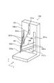
本発明の第1の実施形態について、図1〜図4を用いて説明する。図1及び図2に示すように、パラレルリンクロボット100は、ケース101と、出力部材103と、複数のリニアアクチュエータ104、105、108、110と、複数のリンク機構106、107、109、112と、を有する。なお、104は第1リニアアクチュエータ、105は第2リニアアクチュエータ、108は第3リニアアクチュエータ、110は第4リニアアクチュエータである。また、106は第1リンク機構、107は第2リンク機構、109は第3リンク機構、112は第4リンク機構である。
<First Embodiment>
A first embodiment of the present invention will be described with reference to FIGS. 1 and 2, the parallel link robot 100 includes a case 101, an output member 103, a plurality of linear actuators 104, 105, 108, 110, and a plurality of link mechanisms 106, 107, 109, 112. Have. Reference numeral 104 denotes a first linear actuator, 105 denotes a second linear actuator, 108 denotes a third linear actuator, and 110 denotes a fourth linear actuator. Reference numeral 106 denotes a first link mechanism, 107 denotes a second link mechanism, 109 denotes a third link mechanism, and 112 denotes a fourth link mechanism.

[ケース]
ケース101内には、第1リニアアクチュエータ104、第2リニアアクチュエータ105、第3リニアアクチュエータ108、第4リニアアクチュエータ110を、それぞれの可動部が出力部材側に突出しないように収納する。ケース101はベース部材を兼ねており、複数のリニアアクチュエータ104、105、108、110が、ケース101を構成する略鉛直方向に配設(立設)された支持壁101bのそれぞれの所定の位置に直接又は取付部材などを介して固定されている。
[Case]
In the case 101, the first linear actuator 104, the second linear actuator 105, the third linear actuator 108, and the fourth linear actuator 110 are accommodated so that the respective movable parts do not protrude toward the output member. The case 101 also serves as a base member, and a plurality of linear actuators 104, 105, 108, and 110 are respectively disposed at predetermined positions on the support wall 101 b disposed (standing) in a substantially vertical direction that constitutes the case 101. It is fixed directly or via an attachment member.

また、各リニアアクチュエータの駆動力を後述するリンク機構106、107、109、112を介して出力部材103に伝達するようにしている。そして、各リニアアクチュエータにより駆動されて各リンク機構を駆動する可動部がケース101内に収まるようにしている。更に、ケース101の複数個所に開口部101aを設け、開口部101aを介して、各リニアアクチュエータにより各リンク機構をそれぞれ駆動可能としている。なお、ケース101は一体の構成でなくてもよく、複数の筐体を連結させた構成でもよい。   Further, the driving force of each linear actuator is transmitted to the output member 103 via link mechanisms 106, 107, 109, and 112 described later. And the movable part which drives with each linear actuator and drives each link mechanism is made to fit in the case 101. Furthermore, openings 101a are provided at a plurality of locations of the case 101, and each link mechanism can be driven by each linear actuator via the openings 101a. Note that the case 101 does not have to be an integral configuration, and may have a configuration in which a plurality of casings are connected.

[出力部材]
出力部材103は、ワークの移動や加工などを行うフィンガーやドリルなどの工具を取り付けるものである。このような出力部材103は、所定のz軸方向(鉛直方向)に配設され、例えば、その先端部(下端部)に工具を結合する。後述するように、出力部材103は、z軸(鉛直方向に沿った軸)回りの回転自在である。言い換えれば、出力部材103は、回転軸がz軸と略(実質的に)平行である。本実施形態では、z軸方向を鉛直方向としている。
[Output member]
The output member 103 is for attaching a tool such as a finger or a drill for moving or machining a workpiece. Such an output member 103 is disposed in a predetermined z-axis direction (vertical direction) , and, for example, a tool is coupled to a tip portion (lower end portion) thereof. As will be described later, the output member 103 is rotatable about the z-axis (axis along the vertical direction) . In other words, the rotation axis of the output member 103 is substantially (substantially) parallel to the z axis. In the present embodiment, the z-axis direction is the vertical direction.

なお、出力部材103は軸状の形態を有することが好適であるが、実際に軸状の形態を有さなくても良い。後述するように、平行リンク等のリンク部材が結合されるジョイント部(連結部)が略直線上に並べられれば良く、本発明の出力部材はこのような場合も含むものとする。   Note that the output member 103 preferably has an axial shape, but may not actually have an axial shape. As will be described later, joint portions (connecting portions) to which link members such as parallel links are coupled may be arranged on a substantially straight line, and the output member of the present invention includes such a case.

[第1リニアアクチュエータ及び第2リニアアクチュエータ]
第1リニアアクチュエータ104及び第2リニアアクチュエータ105は、それぞれが出力部材103をxyz空間内(三次元空間内)で移動させるための駆動源となる直動型のアクチュエータの一例である。これら第1リニアアクチュエータ104及び第2リニアアクチュエータ105は、それぞれレール(固定子)104A(第1レール)、105A(第2レール)をz軸方向(鉛直方向)に配置している。レール104A、105Aは、それぞれケース101の支持壁101bの鉛直方向中間部ないし下端寄りに固定されている。即ち、レール104Aとレール105Aとは、支持壁101bのうち鉛直方向下端部側において、第1移動子104a及び第2移動子105aの移動方向と直交する方向に間隔をあけて配置されている。そして、第1リニアアクチュエータ104のレール104Aに第1移動子104aを、第2リニアアクチュエータ105のレール105Aに第2移動子105aを、それぞれレールに沿って移動自在に配置している。
[First linear actuator and second linear actuator]
Each of the first linear actuator 104 and the second linear actuator 105 is an example of a direct acting actuator that serves as a drive source for moving the output member 103 in the xyz space (in the three-dimensional space). In the first linear actuator 104 and the second linear actuator 105, rails (stator) 104A (first rail) and 105A (second rail) are arranged in the z-axis direction (vertical direction), respectively. Each of the rails 104A and 105A is fixed to a vertically middle portion or a lower end of the support wall 101b of the case 101. In other words, the rail 104A and the rail 105A are arranged at intervals in the direction perpendicular to the moving direction of the first moving element 104a and the second moving element 105a on the lower end side in the vertical direction of the support wall 101b. The first moving element 104a is arranged on the rail 104A of the first linear actuator 104, and the second moving element 105a is arranged on the rail 105A of the second linear actuator 105 so as to be movable along the rail.

第1移動子104a、第2移動子105aには、それぞれレール104A、105Aと反対側に、z軸方向と略平行な第1軸104b、第2軸105bがそれぞれ固定されている。このような第1軸104b、第2軸105bは、第1移動子104a、第2移動子105aから突設したそれぞれが一対のアーム104B、105Bの先端に支持固定されている。したがって、第1軸104b、第2軸105bは、それぞれ第1移動子104a、第2移動子105aと共に、z軸方向に移動する。第1軸104bの中心軸線と第2軸105bの中心軸線はz軸に平行な共通の平面内に位置するように配置されている。即ち、第1軸104bと第2軸105b)とは、z軸に平行な共通の平面内を移動する。言い換えれば第1移動子104aと第2移動子105aは、z軸に平行な所定の平面内を移動する。これら第1移動子104a及び第2移動子105aのそれぞれの移動量は、制御部Cにより制御される。制御部Cは、CPUやハードウエア回路又はそれらの組合せからなる。   A first shaft 104b and a second shaft 105b, which are substantially parallel to the z-axis direction, are fixed to the first moving element 104a and the second moving element 105a on the opposite sides of the rails 104A and 105A, respectively. The first shaft 104b and the second shaft 105b are supported and fixed at the tips of the pair of arms 104B and 105B, respectively, protruding from the first and second moving elements 104a and 105a. Accordingly, the first shaft 104b and the second shaft 105b move in the z-axis direction together with the first moving element 104a and the second moving element 105a, respectively. The central axis of the first axis 104b and the central axis of the second axis 105b are arranged so as to be located in a common plane parallel to the z axis. That is, the first axis 104b and the second axis 105b) move in a common plane parallel to the z-axis. In other words, the first moving element 104a and the second moving element 105a move in a predetermined plane parallel to the z axis. The amount of movement of each of the first moving element 104a and the second moving element 105a is controlled by the control unit C. The control unit C includes a CPU, a hardware circuit, or a combination thereof.

なお、第1移動子104aに固定の第1軸104bの下端部には、中間アーム104fがz軸回りの回転自在に支持されている。中間アーム104fは、この第1軸104b(回転軸)からz軸と交差する方向(図示の例では水平方向)に突設され、後述する連動機構110Bにより第1軸104bを中心として回転する。   An intermediate arm 104f is supported at the lower end of the first shaft 104b fixed to the first moving element 104a so as to be rotatable about the z axis. The intermediate arm 104f protrudes from the first axis 104b (rotary axis) in a direction intersecting the z axis (in the illustrated example, the horizontal direction), and rotates about the first axis 104b by an interlocking mechanism 110B described later.

[第3リニアアクチュエータ]
第3リニアアクチュエータ108は、出力部材103をxyz空間内の概ねz軸方向に移動させるための駆動源となる直動型アクチュエータの一例である。この第3リニアアクチュエータ108も、第1リニアアクチュエータ104及び第2リニアアクチュエータ105と同様に、レール(固定子)108A(第3レール)をz軸方向(鉛直方向)に配置している。レール108Aは、ケース101の支持壁101bの鉛直方向上端寄りで、水平方向に関してレール104Aとレール105Aとの間に固定されている。即ち、レール108Aは、レール104Aとレール105Aとで挟まれた部分よりも支持壁101bの鉛直方向上端部側に配置されている。また、レール108Aは、レール104A及びレール105Aの長さよりも短い長さを有する。そして、第3リニアアクチュエータ108のレール108Aに第3移動子108aをレールに沿って移動自在に配置している。
[Third linear actuator]
The third linear actuator 108 is an example of a direct acting actuator that serves as a drive source for moving the output member 103 in the z-axis direction in the xyz space. Similarly to the first linear actuator 104 and the second linear actuator 105, the third linear actuator 108 also has a rail (stator) 108A (third rail) arranged in the z-axis direction (vertical direction). The rail 108A is fixed between the rail 104A and the rail 105A in the horizontal direction near the upper end in the vertical direction of the support wall 101b of the case 101. That is, the rail 108A is disposed on the upper end side in the vertical direction of the support wall 101b with respect to the portion sandwiched between the rail 104A and the rail 105A. The rail 108A has a length shorter than the length of the rail 104A and the rail 105A. A third moving element 108a is arranged on the rail 108A of the third linear actuator 108 so as to be movable along the rail.

第3移動子108aには、レール108Aと反対側にz軸方向と平行な第3軸108bが固定されている。このような第3軸108bは、第3移動子108aから突設した一対のアーム108Bの先端に支持固定されている。したがって、第3軸108bは、第3移動子108aと共にz軸方向に移動する。なお、第3軸108bは軸状の部材として図示したが、後述のジョイント部109cを連結するための部材であればよく、軸状の部材である必要はない。第3移動子108aは、第1移動子104aと第2移動子105aとともに、z軸に平行な共通の平面(上述の所定の平面)内又はその近傍を移動するようになっている。第3移動子108aの移動量も、制御部Cにより制御される。なお、ジョイント部109c、第1軸104b、第2軸105bが同一平面内を移動するように構成すれば、出力部材103の位置決めの演算を簡単化できる。   A third shaft 108b parallel to the z-axis direction is fixed to the third moving element 108a on the side opposite to the rail 108A. The third shaft 108b is supported and fixed at the tips of a pair of arms 108B protruding from the third moving element 108a. Accordingly, the third axis 108b moves in the z-axis direction together with the third moving element 108a. Although the third shaft 108b is illustrated as a shaft-shaped member, it may be a member for connecting a joint portion 109c described later, and need not be a shaft-shaped member. The third moving element 108a moves with or without the first moving element 104a and the second moving element 105a in a common plane parallel to the z axis (the predetermined plane described above) or in the vicinity thereof. The movement amount of the third moving element 108a is also controlled by the control unit C. Note that if the joint portion 109c, the first shaft 104b, and the second shaft 105b are configured to move in the same plane, the positioning calculation of the output member 103 can be simplified.

[第4リニアアクチュエータ]
第4リニアアクチュエータ110は、出力部材103をz軸回り(鉛直軸回り)に回動させるための駆動源となる直動型アクチュエータの一例である。この第4リニアアクチュエータ110も、第1リニアアクチュエータ104及び第2リニアアクチュエータ105と同様に、レール(固定子)110Aをz軸方向(鉛直方向)に配置している。レール110Aは、ケース101の支持壁101bの鉛直方向中間部ないし下端寄りで、水平方向に関してレール104Aとレール105Aとの間に固定されている。図示の例の場合、第1アクチュエータ104のレール104Aに隣接した位置に配置している。そして、第4リニアアクチュエータ110のレール110Aに第4移動子110aをレールに沿って移動自在に配置している。また、レール110Aは、鉛直方向の長さをレール104Aよりも長くして、第4移動子110aの移動範囲を第1移動子104aの移動範囲よりも大きくしている。本実施形態では、第4移動子110aは、第1移動子104aと、第2移動子105aと、第3移動子108aとともにz軸に平行な共通の平面(上述の所定の平面)内又はその近傍を移動するように配置されている。第4移動子110aの移動量も、制御部Cにより制御される。
[Fourth linear actuator]
The fourth linear actuator 110 is an example of a direct acting actuator that serves as a drive source for rotating the output member 103 about the z axis (about the vertical axis). Similarly to the first linear actuator 104 and the second linear actuator 105, the fourth linear actuator 110 also has rails (stator) 110A arranged in the z-axis direction (vertical direction). The rail 110 </ b> A is fixed between the rail 104 </ b> A and the rail 105 </ b> A in the horizontal direction near the vertical middle portion or the lower end of the support wall 101 b of the case 101. In the case of the illustrated example, the first actuator 104 is disposed at a position adjacent to the rail 104A. A fourth moving element 110a is arranged on the rail 110A of the fourth linear actuator 110 so as to be movable along the rail. Further, the rail 110A has a length in the vertical direction longer than that of the rail 104A, so that the moving range of the fourth moving element 110a is larger than the moving range of the first moving element 104a. In the present embodiment, the fourth movable element 110a is in a common plane (predetermined plane described above) parallel to the z axis together with the first movable element 104a, the second movable element 105a, and the third movable element 108a. It is arranged to move in the vicinity. The moving amount of the fourth moving element 110a is also controlled by the control unit C.

[連動機構]
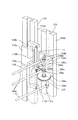
第4移動子110aには、図3に示す様に、レール110Aと反対側に、連動機構110Bが配置されている。この連動機構110Bは、第1移動子104aと第4移動子110aとの間に設けられ、これら両移動子104a、110aの相対移動に連動して中間アーム104fを回転させる。このために連動機構110Bは、一対の支持部材110b、110cと、ワイヤ111と、2個の補助プーリ104cと、プーリ104eとを有する。
[Interlock mechanism]
As shown in FIG. 3, the interlocking mechanism 110B is disposed on the fourth moving element 110a on the side opposite to the rail 110A. The interlocking mechanism 110B is provided between the first moving element 104a and the fourth moving element 110a, and rotates the intermediate arm 104f in conjunction with the relative movement of the both moving elements 104a and 110a. For this purpose, the interlocking mechanism 110B includes a pair of support members 110b and 110c, a wire 111, two auxiliary pulleys 104c, and a pulley 104e.

一対の支持部材110b、110cは、それぞれ基端部が第4移動子110aに固定され、互いに鉛直方向逆側に延出するように構成されている。そして、先端寄り部分を水平方向に関して同方向に折り曲げ、その先端にワイヤ111の両端部をそれぞれ固定している。2個の補助プーリ104cは、それぞれ第1移動子104a上にレール104Aと反対側に突出するように鉛直方向に並べて固定されている。プーリ104eは、第1軸104bの下端部に軸受104dを介して回転自在に支持されている。このプーリ104eには、中間アーム104fが相対回転不能に固定されている。即ち、中間アーム104fは、第1リニアアクチュエータ104の移動子104aにz軸回り(第1軸104b回り)の回転自在に支持されている。また、中間アーム104fは、この回転軸(第1軸104b)からz軸と交差する方向(図示の例の場合は水平方向)に突設されている。   The pair of support members 110b and 110c are configured such that their base ends are fixed to the fourth moving element 110a and extend to opposite sides in the vertical direction. Then, the portion near the tip is bent in the same direction with respect to the horizontal direction, and both ends of the wire 111 are fixed to the tip. The two auxiliary pulleys 104c are fixed side by side in the vertical direction so as to protrude on the opposite side of the rail 104A on the first moving element 104a. The pulley 104e is rotatably supported on the lower end portion of the first shaft 104b via a bearing 104d. An intermediate arm 104f is fixed to the pulley 104e so as not to be relatively rotatable. That is, the intermediate arm 104f is supported by the movable element 104a of the first linear actuator 104 so as to be rotatable about the z axis (around the first axis 104b). The intermediate arm 104f protrudes from the rotation axis (first axis 104b) in a direction intersecting the z axis (in the illustrated example, the horizontal direction).

ワイヤ111は、両端部をこのように一対の支持部材110b、110cの先端に固定すると共に、中間部を2個の補助プーリ104cを介してプーリ104eに弛まないように巻き付けている。即ち、一端部が上側の支持部材110bの先端に固定され、鉛直方向に垂下されたワイヤ111を、上側の補助プーリ104cに巻き付けて、このワイヤ111の方向を凡そ水平方向に変える。水平方向に曲げられたワイヤ111はプーリ104eに巻回され、下側の補助プーリ104cに巻き付けて、このワイヤ111の方向を略鉛直方向に変える。そして、ワイヤ111の他端部を下側の支持部材110cの先端に固定している。   Both ends of the wire 111 are fixed to the tips of the pair of support members 110b and 110c as described above, and an intermediate portion is wound around the pulley 104e via the two auxiliary pulleys 104c. That is, the wire 111 having one end fixed to the tip of the upper support member 110b and suspended vertically is wound around the upper auxiliary pulley 104c, and the direction of the wire 111 is changed to a substantially horizontal direction. The wire 111 bent in the horizontal direction is wound around the pulley 104e, wound around the auxiliary pulley 104c on the lower side, and the direction of the wire 111 is changed to a substantially vertical direction. The other end of the wire 111 is fixed to the tip of the lower support member 110c.

これにより、第1移動子104aと第4移動子110aとが相対移動すると、ワイヤ111のプーリ104eに巻き付けている位置が変化して、このプーリ104eが回転する。そして、プーリ104eに固定した中間アーム104fも回転する。なお、ワイヤ111としては、柔軟性が高く伸びの起こりにくいものであればどのような材質のものでも使用可能である。また、ワイヤに代えて平ベルトやタイミングベルトなどの様々な紐状、帯状の動力伝達手段を使用することができる。   As a result, when the first moving element 104a and the fourth moving element 110a move relative to each other, the position of the wire 111 wound around the pulley 104e changes, and the pulley 104e rotates. Then, the intermediate arm 104f fixed to the pulley 104e also rotates. As the wire 111, any material can be used as long as it is highly flexible and hardly stretches. Further, various string-like or belt-like power transmission means such as a flat belt and a timing belt can be used instead of the wire.

また、移動子104a、110aの相対移動に連動して中間アーム104fを回転させる連動機構は、複数のギヤを組み合わせたギヤ伝達機構などの他の構造であっても良い。例えば、ラックとピニオンを使用した構造が考えられる。即ち、第4移動子110aにz軸と平行にラックギヤを設け、第1移動子104aにこのラックギヤと噛み合うピニオンギヤと、このピニオンギヤに連動する第1の傘歯ギヤと、第1の傘歯ギヤに噛み合いz軸回りに回転する第2の傘歯ギヤを設ける。また、第2の傘歯ギヤに中間アーム104fを設ける。そして、第4移動子110aと第1移動子104aとを相対移動させることにより、ラックギヤと噛み合うピニオンギヤが回転し、その回転が傘歯ギヤを介して中間アーム104fに伝達される。   Further, the interlocking mechanism that rotates the intermediate arm 104f in conjunction with the relative movement of the movers 104a and 110a may be another structure such as a gear transmission mechanism that combines a plurality of gears. For example, a structure using a rack and a pinion can be considered. That is, the fourth mover 110a is provided with a rack gear parallel to the z-axis, the first mover 104a is engaged with the pinion gear, the first bevel gear that is interlocked with the pinion gear, and the first bevel gear. A second bevel gear that rotates around the meshing z-axis is provided. Further, an intermediate arm 104f is provided on the second bevel gear. Then, by relatively moving the fourth moving element 110a and the first moving element 104a, the pinion gear meshing with the rack gear rotates, and the rotation is transmitted to the intermediate arm 104f via the bevel gear.

上述のような第1、第2、第3、第4各リニアアクチュエータとしては、リニアモータ、リニアステッピングモータなどが使用可能である。また、モータなどの回転型のアクチュエータと、リードスクリューなどの回転を直進運動に変換する機構とを組み合わせて、リニアアクチュエータを構成することもできる。また、リニア型のアクチュエータは、サーボモータ、ステッピングモータ、超音波モータ等の電動アクチュエータ以外に、油圧などの他の動力により駆動されるものでもよい。   As each of the first, second, third, and fourth linear actuators as described above, a linear motor, a linear stepping motor, or the like can be used. In addition, a linear actuator can be configured by combining a rotary actuator such as a motor and a mechanism that converts rotation of a lead screw or the like into a linear motion. The linear actuator may be driven by other power such as hydraulic pressure in addition to an electric actuator such as a servo motor, a stepping motor, or an ultrasonic motor.

[第1リンク機構及び第2リンク機構]
第1リンク機構106及び第2リンク機構107は、出力部材103と第1移動子104aとの間、及び、出力部材103と第2移動子105aとの間に、それぞれ設けられている。そして、後述するように出力部材103の回転軸をz軸に略平行に保つように保持する機能を有するとともに、第1リニアアクチュエータ104及び第2リニアアクチュエータ105の駆動により出力部材103を移動する機能を有している。
[First link mechanism and second link mechanism]
The first link mechanism 106 and the second link mechanism 107 are provided between the output member 103 and the first moving element 104a and between the output member 103 and the second moving element 105a, respectively. As described later, the output member 103 has a function of holding the rotation axis of the output member 103 so as to be substantially parallel to the z axis, and a function of moving the output member 103 by driving the first linear actuator 104 and the second linear actuator 105 have.

出力部材103とz軸との略平行を保つための平行リンク機構の一例である第1リンク機構106は、第1軸104bと、出力部材103と、複数の第1リンク部材である2本の第1リンクバー106aとを有する構成になっている。また、平行リンク機構の一例である第2リンク機構107は、第2軸105bと、出力部材103と、複数の第2リンク部材である2本の第2リンクバー107aとを有する構成になっている。なお、第1リンクバー106aと第2リンクバー107aとは、それぞれ3本以上としても良い。また、複数の第1リンクバー106a、複数の第2リンクバー107aは、それぞれz軸方向から見て位置が略同じで互いに平行に配置されている。   The first link mechanism 106, which is an example of a parallel link mechanism for keeping the output member 103 and the z-axis substantially parallel, includes a first shaft 104b, the output member 103, and a plurality of first link members. The first link bar 106a is included. The second link mechanism 107, which is an example of a parallel link mechanism, includes a second shaft 105b, an output member 103, and two second link bars 107a that are a plurality of second link members. Yes. The first link bar 106a and the second link bar 107a may each be three or more. The plurality of first link bars 106a and the plurality of second link bars 107a are arranged in parallel with each other at substantially the same positions when viewed from the z-axis direction.

第1軸104bは、上述のようにz軸と平行に配置され、第1リニアアクチュエータ104の駆動によりz軸方向に沿って移動させられる。また、第2軸105bも、上述のようにz軸と平行に配置され、第2リニアアクチュエータ105の駆動によりz軸方向に沿って移動させられる。なお、第1軸104b、第2軸105bは軸状の形態を有することが好適であるが、実際に軸状の形態を有さなくてもよく、平行リンクのリンク部材であるリンクバーが結合されるジョイントをz軸(鉛直線)に略平行な直線上に並べてあれば良い。   The first shaft 104b is arranged in parallel with the z-axis as described above, and is moved along the z-axis direction by driving the first linear actuator 104. The second shaft 105b is also disposed in parallel with the z-axis as described above, and is moved along the z-axis direction by driving the second linear actuator 105. The first shaft 104b and the second shaft 105b preferably have an axial shape. However, the first shaft 104b and the second shaft 105b may not actually have an axial shape, and a link bar that is a link member of a parallel link is coupled. The joints to be used may be arranged on a straight line substantially parallel to the z axis (vertical line).

第1リンク機構106の2本の第1リンクバー106aは、同じ実効長(後述する両端のジョイント部の可動中心位置間距離)を有し、互いに平行に配置された状態で、第1軸104bと出力部材103とを接続する。また、2本の第1リンクバー106aは、z軸方向から見て位置が略同等である。本実施形態では、第1軸104b、出力部材103、2本の第1リンクバー106aで鉛直方向の平行リンク機構を構成している。このため、出力部材103の位置に拘らず、第1軸104bと出力部材103との平行、2本の第1リンクバー106aの平行がそれぞれ保持される。   The two first link bars 106a of the first link mechanism 106 have the same effective length (distance between movable center positions of joint portions at both ends, which will be described later), and are arranged in parallel to each other in the first shaft 104b. And the output member 103 are connected. Further, the positions of the two first link bars 106a are substantially the same when viewed from the z-axis direction. In the present embodiment, the first shaft 104b, the output member 103, and the two first link bars 106a constitute a vertical parallel link mechanism. Therefore, regardless of the position of the output member 103, the parallelism between the first shaft 104b and the output member 103 and the parallelism of the two first link bars 106a are maintained.

第2リンク機構107の2本の第2リンクバー107aは、同じ実効長を有し、互いに平行に配置された状態で、第2軸105bと出力部材103とを接続する。また、2本の第1リンクバー107aは、z軸方向から見て位置が略同等である。このように、本実施形態では、第2軸105b、出力部材103、2本の第2リンクバー107aで鉛直方向の平行リンク機構を構成している。このため、出力部材103の位置に拘らず、第2軸105bと出力部材103との平行、2本の第2リンクバー107aの平行がそれぞれ保持される。   The two second link bars 107a of the second link mechanism 107 have the same effective length and connect the second shaft 105b and the output member 103 in a state of being arranged in parallel to each other. Further, the positions of the two first link bars 107a are substantially equal when viewed from the z-axis direction. Thus, in the present embodiment, the second shaft 105b, the output member 103, and the two second link bars 107a constitute a vertical parallel link mechanism. Therefore, regardless of the position of the output member 103, the parallelism between the second shaft 105b and the output member 103 and the parallelism of the two second link bars 107a are maintained.

また、本実施形態の場合、出力部材103がx、y、z軸の何れの方向にも移動できるように、第1リンク機構106及び第2リンク機構107の各ジョイント部(連結部)を構成している。まず、第1リンク機構106は、出力部材103と2本の第1リンクバー106aの一端部とを、複数の(2個の)第1出力側ジョイント部106bによりそれぞれ連結している。また、第1軸104bと2本の第1リンクバー106aの他端部とを、複数の(2個の)第1駆動側ジョイント部106cによりそれぞれ連結している。   In the case of this embodiment, each joint portion (connecting portion) of the first link mechanism 106 and the second link mechanism 107 is configured so that the output member 103 can move in any direction of the x, y, and z axes. doing. First, the first link mechanism 106 connects the output member 103 and one end portions of the two first link bars 106a by a plurality of (two) first output side joint portions 106b. Further, the first shaft 104b and the other end portions of the two first link bars 106a are respectively connected by a plurality of (two) first drive side joint portions 106c.

第2リンク機構107は、出力部材103と2本の第2リンクバー107aの一端部とを、複数の(2個の)第2出力側ジョイント部107bによりそれぞれ連結している。また、第2軸105bと2本の第2リンクバー107aの他端部とを、複数の(2個の)第2駆動側ジョイント部107cによりそれぞれ連結している。   The second link mechanism 107 connects the output member 103 and one end portions of the two second link bars 107a by a plurality of (two) second output side joint portions 107b. Further, the second shaft 105b and the other end portions of the two second link bars 107a are respectively connected by a plurality of (two) second drive side joint portions 107c.

2個の第1出力側ジョイント部106bは、少なくとも、出力部材103に対して第1リンクバー106aを、z軸回りの回動、及び、出力部材103及び第1リンクバー106aの配設方向の両方に直交する直交軸を中心として回動自在である。2個の第2出力側ジョイント部107bは、少なくとも、出力部材103に対する第2リンクバー107aの、z軸回りの回動、及び、出力部材103及び第2リンクバー107aの配設方向の両方に直交する直交軸を中心として回動自在である。即ち、第1出力側ジョイント部106b及び第2出力側ジョイント部107bは、少なくとも2自由度を有する。   The two first output side joint portions 106b at least move the first link bar 106a relative to the output member 103 around the z axis and in the arrangement direction of the output member 103 and the first link bar 106a. It is rotatable about an orthogonal axis that is orthogonal to both. The two second output side joint portions 107b are at least in both the rotation of the second link bar 107a relative to the output member 103 around the z axis and the arrangement direction of the output member 103 and the second link bar 107a. It is freely rotatable around an orthogonal axis that is orthogonal. That is, the first output side joint portion 106b and the second output side joint portion 107b have at least two degrees of freedom.

2個の第1駆動側ジョイント部106cは、少なくとも、第1軸104bに対して第1リンクバー106aを、z軸回りの回動、及び、第1軸104b及び第1リンクバー106aの配設方向の両方に直交する直交軸を中心として回動自在である。2個の第2駆動側ジョイント部107cは、少なくとも、第2軸105bに対して第2リンクバー107aを、z軸回りの回動、及び、第2軸105b及び第2リンクバー107aの配設方向の両方に直交する直交軸を中心として回動自在である。即ち、第1駆動側ジョイント部106c及び第2駆動側ジョイント部107cも、少なくとも2自由度を有する。なお、第1軸104bと第2軸105bを軸受等により回転自在に支持すれば、第1駆動側ジョイント部106c及び第2駆動側ジョイント部107cは1自由度のジョイントに変更できる。   The two first drive side joint portions 106c at least move the first link bar 106a relative to the first shaft 104b, rotate about the z axis, and dispose the first shaft 104b and the first link bar 106a. It is freely rotatable around an orthogonal axis that is orthogonal to both directions. The two second drive side joint portions 107c at least move the second link bar 107a relative to the second shaft 105b, rotate about the z axis, and dispose the second shaft 105b and the second link bar 107a. It is freely rotatable around an orthogonal axis that is orthogonal to both directions. That is, the first drive side joint part 106c and the second drive side joint part 107c also have at least two degrees of freedom. In addition, if the 1st axis | shaft 104b and the 2nd axis | shaft 105b are rotatably supported by a bearing etc., the 1st drive side joint part 106c and the 2nd drive side joint part 107c can be changed into a 1 degree-of-freedom joint.

[出力部材のz軸に交差する方向への移動]
上述のように、第1リニアアクチュエータ104と出力部材103との間、及び、第2リニアアクチュエータ105と出力部材103との間に、それぞれ平行リンク機構を設けている。そして、これら2個のリニアアクチュエータにより出力部材103をz軸に交差する方向(即ち、概ね水平方向)に移動可能としている。即ち、制御部Cが第3移動子108aの位置を固定したまま、第1移動子104a及び第2移動子105aを、z軸方向にそれぞれ任意の量移動させる。これにより出力部材103のz軸方向の位置は概ね変化しない一方で、第1軸104b及び第2軸105bと出力部材103とのz軸に交差する方向の距離が変化して、出力部材103が概ね水平方向に移動させられる。
[Movement of output member in direction intersecting z-axis]
As described above, the parallel link mechanisms are provided between the first linear actuator 104 and the output member 103 and between the second linear actuator 105 and the output member 103, respectively. These two linear actuators allow the output member 103 to move in a direction intersecting the z axis (that is, generally in the horizontal direction). That is, the control unit C moves the first moving element 104a and the second moving element 105a in arbitrary amounts in the z-axis direction while fixing the position of the third moving element 108a. As a result, the position of the output member 103 in the z-axis direction does not change substantially, while the distance between the first shaft 104b and the second shaft 105b and the output member 103 in the direction intersecting the z-axis changes, and the output member 103 It can be moved almost horizontally.

このとき、第1軸104b及び第2軸105bはz軸方向に対して略平行を保ちながら移動される。このため、第1リニアアクチュエータ104及び第2リニアアクチュエータ105の駆動により、出力部材103の回転軸のz軸方向(鉛直方向)に対する姿勢を保ちながら、出力部材103をz軸に交差する概ね水平の方向に移動させることができる。   At this time, the first shaft 104b and the second shaft 105b are moved while being substantially parallel to the z-axis direction. For this reason, by driving the first linear actuator 104 and the second linear actuator 105, the output member 103 is maintained in a substantially horizontal direction intersecting the z axis while maintaining the posture of the rotation axis of the output member 103 with respect to the z axis direction (vertical direction). Can be moved in the direction.

また、本実施形態の場合、出力部材103側の2個の第1出力側ジョイント部106bと、出力部材103側の2個の第2出力側ジョイント部107bとが、z軸と略平行な同一軸上、即ち出力部材103上に配置されている。これにより、第1リニアアクチュエータ104から出力部材103におよぼす位置決め力の作用する位置と、第2リニアアクチュエータ105から出力部材103におよぼす位置決め力の作用する位置とが、上方から見て必ず一致する。このため、両リニアアクチュエータからの位置決め力の作用する位置の食い違いがある場合に生じる出力部材103の位置決め誤差を回避できる。なお、複数の第1出力側ジョイント部106bを結ぶ直線と、複数の第2出力側ジョイント部107bを結ぶ直線とを実質的に一致させていればよく、構造上の要求から僅かにずらして配置してもよい。   In the case of the present embodiment, the two first output side joint portions 106b on the output member 103 side and the two second output side joint portions 107b on the output member 103 side are the same substantially parallel to the z axis. It is disposed on the shaft, that is, on the output member 103. As a result, the position where the positioning force acts on the output member 103 from the first linear actuator 104 and the position where the positioning force acts on the output member 103 from the second linear actuator 105 always coincide with each other when viewed from above. For this reason, it is possible to avoid the positioning error of the output member 103 that occurs when there is a discrepancy between the positions where the positioning forces from the two linear actuators act. The straight lines connecting the plurality of first output side joint portions 106b and the straight lines connecting the plurality of second output side joint portions 107b need only be substantially matched, and are slightly shifted from structural requirements. May be.

[第3リンク機構]
第3リンク機構109は、出力部材103と第3移動子108aとの間に設けられ、第3リニアアクチュエータ108の駆動により出力部材103を概ねz軸方向に移動可能としている。このような第3リンク機構109は、第3リンク部材である第3リンクバー109aと、出力部材103とにより構成される。
[Third link mechanism]
The third link mechanism 109 is provided between the output member 103 and the third moving element 108a, and is capable of moving the output member 103 substantially in the z-axis direction by driving the third linear actuator 108. Such a third link mechanism 109 is configured by a third link bar 109 a that is a third link member and an output member 103.

第3リンクバー109aは、一端部を出力部材103の中間部に第3出力側ジョイント部109bにより連結し、他端部を第3軸108bの先端部(下端部)に第3駆動側ジョイント部109cにより連結している。図示の例の場合、第3出力側ジョイント部109bは、一対の第1出力側ジョイント部106bの間で、且つ、一対の第2出力側ジョイント部107bの間に配置されている。   The third link bar 109a has one end connected to the intermediate portion of the output member 103 by the third output side joint portion 109b, and the other end connected to the distal end portion (lower end portion) of the third shaft 108b. They are connected by 109c. In the illustrated example, the third output side joint portion 109b is disposed between the pair of first output side joint portions 106b and between the pair of second output side joint portions 107b.

この第3出力側ジョイント部109bは、少なくとも、出力部材103に対する第3リンクバー109aの、z軸回りの回動、及び、出力部材103及び第3リンクバー109aの配設方向の両方に直交する直交軸を中心とした回動を可能とする。即ち、第3出力側ジョイント部109bは、少なくとも2自由度を有する。第3駆動側ジョイント部109cは、少なくとも、第3軸108bに対する第3リンクバー109aの、z軸回りの回動、及び、第3軸108b及び第3リンクバー109aの配設方向の両方に直交する直交軸を中心とした回動を可能とする。即ち、第3駆動側ジョイント部109cは、少なくとも2自由度を有する。   The third output side joint portion 109b is orthogonal to both at least the rotation of the third link bar 109a around the z axis relative to the output member 103 and the arrangement direction of the output member 103 and the third link bar 109a. Allows rotation around an orthogonal axis. That is, the third output side joint portion 109b has at least two degrees of freedom. The third drive side joint part 109c is orthogonal to both at least the rotation of the third link bar 109a around the z axis relative to the third axis 108b and the arrangement direction of the third axis 108b and the third link bar 109a. It is possible to rotate around the orthogonal axis. In other words, the third drive side joint portion 109c has at least two degrees of freedom.

なお、図2に丸印で示した2自由度のジョイント部106b、107b、109b等としては、例えば図3にジョイント部106cとして例示する構造のジョイントを適用できる。図3のジョイントは、矢印Aに示すような支持軸の周りに1回転以上回転する自由度と、矢印Bに示すような支持軸に略直角な軸周りに所定の振れ角度範囲内で回動する自由度を有する。後述する他の2自由度のジョイントも、この図3に例示する構造を有するものが好適である。このような2自由度のジョイントを用いれば、リンクバーの配設方向回りの回転の自由度を有さないので、平行リンク機構のねじれを防止することができる。   As the joint portions 106b, 107b, 109b having two degrees of freedom indicated by circles in FIG. 2, for example, a joint having a structure exemplified as the joint portion 106c in FIG. 3 can be applied. The joint of FIG. 3 rotates within a predetermined deflection angle range around an axis substantially perpendicular to the support shaft as shown by the arrow B and a degree of freedom of rotating around the support shaft as shown by the arrow A. Have the freedom to The other two-degree-of-freedom joint to be described later preferably has the structure illustrated in FIG. If such a two-degree-of-freedom joint is used, the parallel link mechanism can be prevented from being twisted because there is no degree of freedom of rotation around the link bar arrangement direction.

[出力部材の上下移動]
制御部Cにより第3リニアアクチュエータ108を駆動すると、第3移動子108aがz軸方向に沿って移動し、第3軸108bの先端に第3リンクバー109aを介して接続された出力部材103が概ね鉛直方向に移動する。厳密には、第1リニアアクチュエータ104及び第2リニアアクチュエータ105の移動子104a、105aを固定のまま、第3リニアアクチュエータ108のみ駆動すると出力部材103は仮想的な円弧上を移動する。
[Up-down movement of output member]
When the control unit C drives the third linear actuator 108, the third moving element 108a moves along the z-axis direction, and the output member 103 connected to the tip of the third shaft 108b via the third link bar 109a. Moves in a generally vertical direction. Strictly speaking, when only the third linear actuator 108 is driven while the movers 104a and 105a of the first linear actuator 104 and the second linear actuator 105 are fixed, the output member 103 moves on a virtual arc.

したがって、第1リニアアクチュエータ104及び第2リニアアクチュエータ105の駆動による出力部材103のz軸に交差する方向への移動に対応させて、第3リニアアクチュエータ108を駆動すれば、出力部材103を概ねz軸方向へ移動することができる。これにより、xyz空間内で出力部材103を位置決め可能である。具体的には、第1リニアアクチュエータ104及び第2リニアアクチュエータ105の駆動による出力部材103の概ね水平方向への移動と共に、第3リニアアクチュエータ108の駆動による概ねz軸方向への移動を併用すれば、所定の範囲内の所望の位置に出力部材103を移動することができる。   Therefore, if the third linear actuator 108 is driven in response to the movement of the output member 103 in the direction intersecting the z axis by driving the first linear actuator 104 and the second linear actuator 105, the output member 103 is substantially z. It can move in the axial direction. As a result, the output member 103 can be positioned in the xyz space. Specifically, if the movement of the output member 103 in the substantially horizontal direction by driving the first linear actuator 104 and the second linear actuator 105 is combined with the movement in the substantially z-axis direction by driving the third linear actuator 108, The output member 103 can be moved to a desired position within a predetermined range.

また、前述のように、第1リニアアクチュエータ104と出力部材103との間、及び、第2リニアアクチュエータ105と出力部材103との間に、それぞれ平行リンク機構を設けている。このため、出力部材103の水平方向及び鉛直方向の任意の移動に拘らず、出力部材103を鉛直方向と略平行な状態に維持できる。   In addition, as described above, the parallel link mechanisms are provided between the first linear actuator 104 and the output member 103 and between the second linear actuator 105 and the output member 103, respectively. For this reason, irrespective of the arbitrary movement of the output member 103 in the horizontal direction and the vertical direction, the output member 103 can be maintained in a state substantially parallel to the vertical direction.

また、第3リニアアクチュエータ108の駆動により、出力部材103を上下方向に移動すると、第1リンクバー106aと第2リンクバー107aの水平からの傾斜の角度が変化する。このため、出力部材103の3次元空間内の移動位置は、第1、第2、第3各リンクバー106a、107a、109aの傾斜を考慮して、第1、第2、第3各リニアアクチュエータ104、105、108の駆動量から幾何学的に算出できる。ここで、リニアアクチュエータの駆動量は、移動子の移動距離に相当する。   Further, when the output member 103 is moved in the vertical direction by driving the third linear actuator 108, the angle of inclination of the first link bar 106a and the second link bar 107a from the horizontal changes. For this reason, the movement position of the output member 103 in the three-dimensional space takes into account the inclination of the first, second, and third link bars 106a, 107a, and 109a, and the first, second, and third linear actuators. It can be calculated geometrically from the driving amounts of 104, 105, and 108. Here, the driving amount of the linear actuator corresponds to the moving distance of the moving element.

なお、第1、第2リニアアクチュエータ104、105の駆動量から概略の位置を算出し、それを第3リニアアクチュエータ108の駆動量に応じて補正することで、出力部材103のxyz空間内の正確な移動位置を算出するようにしても良い。また、算出値を予め制御部C内の数値テーブルに格納しておき、目標とする移動位置に基づいて第1、第2、第3リニアアクチュエータ104、105、108の駆動量をこの数値テーブルから求めることが好適である。また、移動位置から第1、第2、第3リニアアクチュエータ104、105、108の駆動量を逆算する算出式を用いても良い。以上のようにして出力部材103の移動位置と第1、第2、第3リニアアクチュエータ104、105、108の駆動量を関係付けることで、出力部材103に固定の出力部材103の3次元位置(xyz位置)の位置決めが可能となる。なお、本実施形態の場合、第1軸104b、第2軸105bのそれぞれの中心軸線がz軸に平行な共通の平面内にあり、第3軸108bに連結されるジョイント109cの中心がその平面内又はその平面に概ね沿って移動するため、上述のように出力部材の位置を幾何学的に算出することは容易である。   The approximate position of the output member 103 in the xyz space of the output member 103 is calculated by calculating the approximate position from the drive amount of the first and second linear actuators 104 and 105 and correcting it based on the drive amount of the third linear actuator 108. It is also possible to calculate a simple movement position. The calculated values are stored in advance in a numerical table in the control unit C, and the driving amounts of the first, second, and third linear actuators 104, 105, and 108 are calculated from the numerical table based on the target movement position. It is preferable to obtain it. Also, a calculation formula that reversely calculates the driving amount of the first, second, and third linear actuators 104, 105, and 108 from the movement position may be used. By associating the moving position of the output member 103 with the driving amounts of the first, second, and third linear actuators 104, 105, and 108 as described above, the three-dimensional position of the output member 103 fixed to the output member 103 ( xyz position) can be positioned. In the present embodiment, the central axes of the first shaft 104b and the second shaft 105b are in a common plane parallel to the z axis, and the center of the joint 109c connected to the third shaft 108b is the plane. Since it moves substantially along or in the plane, it is easy to geometrically calculate the position of the output member as described above.

また、本実施形態の場合は第3リンクバー109aの出力部材103側の第3出力側ジョイント部109bは、上述のように出力部材103の中間部に設けられている。そして、この第3出力側ジョイント部109bと、2個の第1出力側ジョイント部106b及び2個の第2出力側ジョイント部107bとを、z軸と略平行な同一軸上(出力部材103の回転軸上)に配置している。これにより、第1、第2、第3各リニアアクチュエータ104、105、108によってそれぞれ出力部材103に対して力を作用させる位置が、上方から見ていつでも一致する。このため、3つのリニアアクチュエータを協働させて行う出力部材103の位置決めの誤差を低減できる。   In the case of the present embodiment, the third output side joint portion 109b on the output member 103 side of the third link bar 109a is provided at the intermediate portion of the output member 103 as described above. Then, the third output side joint portion 109b, the two first output side joint portions 106b and the two second output side joint portions 107b are arranged on the same axis substantially parallel to the z axis (of the output member 103). On the axis of rotation). As a result, the positions at which forces are applied to the output member 103 by the first, second, and third linear actuators 104, 105, and 108 are always coincident when viewed from above. For this reason, the positioning error of the output member 103 performed by cooperating the three linear actuators can be reduced.

また、本実施形態のように、第3リンクバー109aの第3出力側ジョイント部109bを設ける位置を、出力部材103の中間部(特に中央付近)にすることが好ましい。このようにすれば、他のリンクバーから作用する力と第3リンクバー109aから作用する力とのバランスが良好になり、出力部材103の傾きを防止できる。   Further, as in the present embodiment, the position where the third output side joint portion 109b of the third link bar 109a is provided is preferably an intermediate portion (particularly near the center) of the output member 103. In this way, the balance between the force acting from the other link bar and the force acting from the third link bar 109a becomes good, and the inclination of the output member 103 can be prevented.

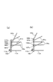
また、本実施形態では、2本の第1リンクバー106aと2本の第2リンクバー107aを出力部材103に対して交互に接続している。但し、図4(a)に示す様に、2本の第1リンクバー106aの配置間隔を2本の第2リンクバー107aの配置間隔よりも狭くしても良い。そして、出力部材103に対する2本の第1リンクバー106aの接続位置を、同じく2本の第2リンクバー107aの2つの接続位置に挟まれた位置に配置する。これにより、出力部材103に対して水平方向に掛かる力のバランスが良好となるので、出力部材103の傾きを防止でき好適である。また、2本の第1リンクバー106aの配置間隔を2本の第2リンクバー107aの配置間隔よりも広くしても良い。そして、出力部材103に対する2本の第2リンクバー107aの接続位置を、2本の第1リンクバー106aの2つの接続位置に挟まれた位置に配置する。この場合も、同様に好適である。   In the present embodiment, the two first link bars 106 a and the two second link bars 107 a are alternately connected to the output member 103. However, as shown in FIG. 4A, the arrangement interval between the two first link bars 106a may be narrower than the arrangement interval between the two second link bars 107a. And the connection position of the two 1st link bars 106a with respect to the output member 103 is arrange | positioned in the position pinched | interposed into the two connection positions of the two 2nd link bars 107a. Thereby, since the balance of the force applied to the output member 103 in the horizontal direction becomes good, the inclination of the output member 103 can be prevented, which is preferable. Further, the arrangement interval between the two first link bars 106a may be wider than the arrangement interval between the two second link bars 107a. And the connection position of the two 2nd link bars 107a with respect to the output member 103 is arrange | positioned in the position pinched | interposed into the two connection positions of the two 1st link bars 106a. This case is also suitable as well.

また、2個の第1出力側ジョイント部106bを結ぶ線分の中点と、2個の第2出力側ジョイント部107bを結ぶ線分の中点とが略一致するように、2本の第1リンクバー106a及び2本の第2リンクバー107aをそれぞれ配置すると良い。これにより、第1リニアアクチュエータ104の駆動により出力部材103を移動させる力と、第2モータの駆動により出力部材103を移動させる力とを釣り合わせ易くできる。   In addition, the second points of the two first output side joint portions 106b and the second point of the two second output side joint portions 107b are substantially coincided with the midpoint of the line segments connecting the two second output side joint portions 107b. One link bar 106a and two second link bars 107a may be arranged. Thereby, it is possible to easily balance the force for moving the output member 103 by driving the first linear actuator 104 and the force for moving the output member 103 by driving the second motor.

更に、図4(b)に示す様に、第3リンクバー109aの第3出力側ジョイント部109bを設ける位置を、出力部材103の上端部としても良い。このようにすることで、第3リンクバー109aと他のリンクバーとの干渉を防止することが容易になる。この場合、ジョイント109bを出力部材103の中程に配設した場合と異なり、リンクバー109aから作用する力が出力部材103を略鉛直方向からずらすように働く。すなわち、他のリンクバーの構成する平行リンク機構による出力部材103を略鉛直方向に支持する保持力が十分強い場合は、このような構成を採用することができる。   Furthermore, as shown in FIG. 4B, the position where the third output side joint portion 109b of the third link bar 109a is provided may be the upper end portion of the output member 103. By doing in this way, it becomes easy to prevent interference with the 3rd link bar 109a and other link bars. In this case, unlike the case where the joint 109b is disposed in the middle of the output member 103, the force acting from the link bar 109a acts to shift the output member 103 from the substantially vertical direction. That is, such a configuration can be employed when the holding force for supporting the output member 103 by the parallel link mechanism formed by another link bar in a substantially vertical direction is sufficiently strong.

[第4リンク機構]
上述したように、第1軸104bの下端部には、軸受104dを介してプーリ104eを回転自在に支持している。また、このプーリ104eと共に回転する回転部材である中間アーム104fを配置している。中間アーム104fは、回転軸線から離間した位置に第4駆動側ジョイント部112cを連結可能である。これらプーリ104e及び中間アーム104fは、上述したように、第1移動子104aと第4移動子110aとの相対移動により連動機構110Bを介して、第1軸104bを中心として回転する。そして、中間アーム104fの回転は、第4リンク機構112を介して出力部材103に伝達される。
[Fourth link mechanism]
As described above, the pulley 104e is rotatably supported on the lower end portion of the first shaft 104b via the bearing 104d. An intermediate arm 104f, which is a rotating member that rotates together with the pulley 104e, is disposed. The intermediate arm 104f can connect the fourth drive side joint portion 112c to a position separated from the rotation axis. As described above, the pulley 104e and the intermediate arm 104f rotate around the first shaft 104b via the interlocking mechanism 110B by the relative movement of the first moving element 104a and the fourth moving element 110a. Then, the rotation of the intermediate arm 104 f is transmitted to the output member 103 via the fourth link mechanism 112.

第4リンク機構112は、出力部材103と中間アーム104fとの間に配置される。そして、出力部材103をz軸回りに回転可能としている。このような第4リンク機構112は、出力部材103に設けられた出力延長部材である出力アーム103aと、中間アーム104fとの間に、第4リンク部材である第4リンクバー112aを設けてなる。   The fourth link mechanism 112 is disposed between the output member 103 and the intermediate arm 104f. The output member 103 is rotatable around the z axis. Such a 4th link mechanism 112 provides the 4th link bar 112a which is the 4th link member between the output arm 103a which is the output extension member provided in the output member 103, and the intermediate arm 104f. .

出力アーム103aは、出力部材103の下端寄りでz軸と交差する方向(図示の例では水平方向)に突設され、回転軸線から離間した位置に第4出力側ジョイント部(他のジョイント部)112bを連結可能である。また、出力アーム103aの水平方向の長さと中間アーム104fの水平方向の長さとを同じとしている。第4リンクバー112aの一端部は、第4出力側ジョイント部112bにより出力アーム103aに連結され、第4リンクバー112aの他端部は、第4駆動側ジョイント部112cにより中間アーム104fに連結されている。   The output arm 103a protrudes in a direction (horizontal direction in the illustrated example) intersecting the z-axis near the lower end of the output member 103, and a fourth output-side joint portion (other joint portion) at a position away from the rotation axis. 112b can be connected. Further, the horizontal length of the output arm 103a is the same as the horizontal length of the intermediate arm 104f. One end portion of the fourth link bar 112a is connected to the output arm 103a by the fourth output side joint portion 112b, and the other end portion of the fourth link bar 112a is connected to the intermediate arm 104f by the fourth drive side joint portion 112c. ing.

第4出力側ジョイント部112bは、少なくとも、出力アーム103aに対する第4リンクバー112aの、z軸回りの回動、及び、z軸及び第4リンクバー112aの配設方向に直交する直交軸を中心とした回動を可能としている。また、第4駆動側ジョイント部112cは、少なくとも、中間アーム104fに対する第4リンクバー112aの、z軸回りの回動、及び、z軸及び第4リンクバー112aの配設方向に直交する直交軸を中心とした回動を可能としている。即ち、第4出力側ジョイント部112b及び第4駆動側ジョイント部112cは、少なくとも2自由度を有する。   The fourth output side joint portion 112b is centered on at least an orthogonal axis orthogonal to the rotation direction of the fourth link bar 112a relative to the output arm 103a around the z axis and the arrangement direction of the z axis and the fourth link bar 112a. It is possible to turn. The fourth drive side joint portion 112c has at least an orthogonal axis orthogonal to the rotation of the fourth link bar 112a around the z axis relative to the intermediate arm 104f and the arrangement direction of the z axis and the fourth link bar 112a. Rotation around the center is possible. That is, the fourth output side joint portion 112b and the fourth drive side joint portion 112c have at least two degrees of freedom.

また、本実施形態では第4リンクバー112aの実効長と第1リンクバー106aの実効長とを同じとしている。上述したように、出力アーム103aの長さと中間アーム104fの水平方向の長さも同じであるため、出力アーム103a、中間アーム104f、第4リンクバー112a、第2リンクバー107aで平行リンク機構が構成される。   In the present embodiment, the effective length of the fourth link bar 112a is the same as the effective length of the first link bar 106a. As described above, since the length of the output arm 103a is the same as the length of the intermediate arm 104f in the horizontal direction, the output arm 103a, the intermediate arm 104f, the fourth link bar 112a, and the second link bar 107a constitute a parallel link mechanism. Is done.

[出力部材の回動]
上述のように、中間アーム104fと出力アーム103aとの間に第4リンク機構を設けているため、出力アーム103aはz軸を回転中心として中間アーム104fの回転に追従して回転する。この結果、出力アーム103aの回転角度は中間アーム104fの回転角度に一致する。したがって、制御部Cにより第1リニアアクチュエータ104の第1移動子104aと第4リニアアクチュエータ110の第4移動子110aとの相対位置を制御することで出力部材103の回転を制御可能となっている。
[Rotation of output member]
As described above, since the fourth link mechanism is provided between the intermediate arm 104f and the output arm 103a, the output arm 103a rotates following the rotation of the intermediate arm 104f about the z axis. As a result, the rotation angle of the output arm 103a matches the rotation angle of the intermediate arm 104f. Therefore, the rotation of the output member 103 can be controlled by controlling the relative position between the first moving element 104a of the first linear actuator 104 and the fourth moving element 110a of the fourth linear actuator 110 by the control unit C. .

しかも、出力部材103の回転角度は第4リニアアクチュエータ110の第4移動子110aと第1リニアアクチュエータ104の第1移動子104aとの相対位置により一意に決まる。即ち、第2、第3のリニアアクチュエータ105、108の駆動量に影響を受けない。このため、出力部材103の回転量の制御が簡単に行える。   Moreover, the rotation angle of the output member 103 is uniquely determined by the relative position between the fourth moving element 110 a of the fourth linear actuator 110 and the first moving element 104 a of the first linear actuator 104. That is, the driving amount of the second and third linear actuators 105 and 108 is not affected. For this reason, the rotation amount of the output member 103 can be easily controlled.

なお、図2、図3に示したように、第4リニアアクチュエータ110の第4移動子110aの可動範囲(レール110Aの長さ)は、他のリニアアクチュエータの移動子の可動範囲(レールの長さ)よりも広い(長い)。これにより、出力部材103の所望の位置への位置決めと出力部材103の所望の回転とを組み合わせて支障なく実行可能となっている。即ち、第1、第2、第3の各移動子104a、105a、108aがそれぞれのレールのどの位置に存在しても、第4移動子110aを更に移動させて、出力部材103を回転させられるようにしている。   As shown in FIGS. 2 and 3, the movable range (length of the rail 110A) of the fourth movable element 110a of the fourth linear actuator 110 is the movable range (length of the rail) of the movable elements of other linear actuators. Wider than (long). Thereby, positioning to the desired position of the output member 103 and desired rotation of the output member 103 can be combined and executed without any trouble. That is, regardless of the position of each of the first, second, and third movable elements 104a, 105a, and 108a, the fourth movable element 110a can be further moved to rotate the output member 103. I am doing so.

このように、第4移動子110aを第1移動子104aと相対移動させることにより、出力部材103を回転可能である。一方、出力部材103を回転させずに、出力部材103のxyz空間内での位置決めを図る場合には、第4移動子110aを第1移動子104aと同期して移動させる。このようにすることにより、出力部材103の位置決め動作時の第1リニアアクチュエータ104の負荷を軽減できる。   As described above, the output member 103 can be rotated by moving the fourth moving element 110a relative to the first moving element 104a. On the other hand, when positioning the output member 103 in the xyz space without rotating the output member 103, the fourth moving element 110a is moved in synchronization with the first moving element 104a. By doing so, the load on the first linear actuator 104 during the positioning operation of the output member 103 can be reduced.

[各リニアアクチュエータの配置]
上述したように、第1移動子104aと、第2移動子105aと、第3移動子108aと、第4移動子110aとは、z軸に平行な共通の平面に概ね沿って移動するように配置されている。また、出力部材103は、これら各移動子104a、105a、108a、110aに対してz軸に平行な共通の平面から外れた位置に位置決めされる。
[Arrangement of each linear actuator]
As described above, the first moving element 104a, the second moving element 105a, the third moving element 108a, and the fourth moving element 110a are moved along a common plane parallel to the z-axis. Has been placed. Further, the output member 103 is positioned at a position deviated from a common plane parallel to the z axis with respect to each of the movable elements 104a, 105a, 108a, and 110a.

即ち、出力部材103と、同一平面に概ね沿って移動する第1、第2、第3、第4各移動子104a、105a、108a、110aとの間に、それぞれ第1、第2、第3、第4リンク機構106、107、109、112を設けている。そして、出力部材103を第1、第2、第3、第4各移動子104a、105a、108a、110aに対して水平方向に外れた位置に位置決めするようにしている。このように全ての移動子が同一平面に概ね沿って移動するため、出力部材103の位置を幾何学的に算出することが容易となる。   That is, between the output member 103 and the first, second, third, and fourth movable elements 104a, 105a, 108a, and 110a that move substantially along the same plane, the first, second, and third, respectively. The fourth link mechanisms 106, 107, 109, 112 are provided. The output member 103 is positioned at a position that deviates in the horizontal direction with respect to the first, second, third, and fourth moving elements 104a, 105a, 108a, and 110a. As described above, since all the movable elements move substantially along the same plane, the position of the output member 103 can be easily calculated geometrically.

なお、第1リニアアクチュエータ104と第2リニアアクチュエータ105とは、鉛直方向の位置はほぼ同じ(多少鉛直方向にずれている場合も含む)とし、互いに水平方向にずれた位置に配置している。即ち、z軸方向から見てそれぞれ異なる位置に配置されている。また、第1リンクバー106aの実効長と第2リンクバー107aの実効長を同じとしても良いし、異ならせても良い。   Note that the first linear actuator 104 and the second linear actuator 105 have substantially the same vertical position (including a case where the first linear actuator 104 is slightly deviated in the vertical direction) and are arranged at positions deviated in the horizontal direction. That is, they are arranged at different positions as viewed from the z-axis direction. Further, the effective length of the first link bar 106a and the effective length of the second link bar 107a may be the same or different.

また、第3リニアアクチュエータ108は、水平方向に関し、第1リニアアクチュエータ104と第2リニアアクチュエータ105との間に配置することが好適である。但し、第1リニアアクチュエータ104と同じ位置又は、第2リニアアクチュエータ105と同じ位置としても良い。本実施形態では、第3リニアアクチュエータ108は、第1リニアアクチュエータ104と第2リニアアクチュエータ105との間で、これら2個のリニアアクチュエータ及び出力部材103よりも鉛直方向上方に配置されている。また、第3リニアアクチュエータ108の水平方向の位置は、出力部材103から外れた位置で、且つ、第1リニアアクチュエータ104と第2リニアアクチュエータ105との中央としている。   The third linear actuator 108 is preferably disposed between the first linear actuator 104 and the second linear actuator 105 in the horizontal direction. However, the same position as the first linear actuator 104 or the same position as the second linear actuator 105 may be used. In the present embodiment, the third linear actuator 108 is disposed between the first linear actuator 104 and the second linear actuator 105 above the two linear actuators and the output member 103 in the vertical direction. Further, the position of the third linear actuator 108 in the horizontal direction is a position deviated from the output member 103 and the center of the first linear actuator 104 and the second linear actuator 105.

また、第4リニアアクチュエータ110は、第1リニアアクチュエータ104の水平方向に隣接して配置しているが、第2リニアアクチュエータ105に隣接して配置しても良い。この場合、第4リニアアクチュエータ110と第2リニアアクチュエータ105との間に連動機構を設け、第2移動子105aと第4移動子110aとの相対移動により中間アーム及び第4リンク機構を介して出力部材103を回転させるようにする。   Further, the fourth linear actuator 110 is disposed adjacent to the first linear actuator 104 in the horizontal direction, but may be disposed adjacent to the second linear actuator 105. In this case, an interlocking mechanism is provided between the fourth linear actuator 110 and the second linear actuator 105, and output is performed via the intermediate arm and the fourth link mechanism by the relative movement of the second moving element 105a and the fourth moving element 110a. The member 103 is rotated.

[出力部材103のz軸方向への単純移動]
このように構成される本実施形態の場合、出力部材103を、x軸、y軸方向に関して(z軸方向の上方から見て)任意の位置においてz軸方向の任意の方向(上方向又は下方向)に任意の量移動させる場合に、第1、第2、第3の各リニアアクチュエータ104、105、108を次のように駆動制御する。即ち、制御部Cにより、第1移動子104a、第2移動子105a、第3移動子108aを、それぞれ任意の量と略同じ量だけ上方向(又は下方向)に同時に移動させる。言い換えれば、制御部Cは、鉛直方向における全ての移動子104a、105a、108aの移動を実質的に同等として三次元空間内の出力部材103の鉛直方向のみの位置を決定するように制御する。例えば、出力部材103を水平方向の位置はそのままに鉛直方向上方にh(mm)移動させる場合、第1移動子104a、第2移動子105a、第3移動子108aを、それぞれ鉛直方向上方に略h(mm)移動させる。なお、この際、第4移動子110aの移動量をhよりも多く又は少なくなるように制御して、第1移動子104aとの相対位置を変化させれば、出力部材103の回転角度が変化する。
[Simple movement of output member 103 in z-axis direction]
In the case of the present embodiment configured as described above, the output member 103 is set in any direction (upward or downward) in the z-axis direction at any position in the x-axis and y-axis directions (viewed from above in the z-axis direction) In the case of moving an arbitrary amount in the direction), the first, second, and third linear actuators 104, 105, and 108 are driven and controlled as follows. That is, the control unit C simultaneously moves the first moving element 104a, the second moving element 105a, and the third moving element 108a upward (or downward) by approximately the same amount as each arbitrary amount. In other words, the control unit C performs control so as to determine the position of only the vertical direction of the output member 103 in the three-dimensional space by making the movements of all the moving elements 104a, 105a, and 108a in the vertical direction substantially the same. For example, when the output member 103 is moved h (mm) upward in the vertical direction without changing the horizontal position, the first moving element 104a, the second moving element 105a, and the third moving element 108a are respectively substantially upward in the vertical direction. Move h (mm). At this time, if the movement amount of the fourth moving element 110a is controlled to be larger or smaller than h and the relative position with respect to the first moving element 104a is changed, the rotation angle of the output member 103 changes. To do.

一方、第4移動子110aも鉛直方向上方に他の移動子と同じ量移動させれば、出力部材103の回転角度が維持されつつ、出力部材103が上昇する。言い換えれば、出力部材103の角度を維持しつつ出力部材103をz軸方向の上方向(又は下方向)に任意の量移動させる場合には、第1、第2、第3各リニアアクチュエータ104、105、108及び第4リニアアクチュエータ110を次のように制御する。即ち、第1移動子104a、第2移動子105a、第3移動子108a、及び第4移動子110aを、それぞれz軸方向の上方向(又は下方向)に任意の量と略同じ量移動させる。言い換えれば、制御部Cは、出力部材103の回転角度を所定の角度に維持しつつ鉛直方向における全ての移動子104a、105a、108a、110aの移動を実質的に同等として三次元空間内の出力部材103の鉛直方向のみの位置を決定するように制御する。
On the other hand, if the fourth moving element 110a is also moved in the vertical direction by the same amount as the other moving elements, the output member 103 is raised while the rotation angle of the output member 103 is maintained. In other words, when the output member 103 is moved by an arbitrary amount upward (or downward) in the z-axis direction while maintaining the angle of the output member 103, the first, second, and third linear actuators 104, 105 and 108 and the fourth linear actuator 110 are controlled as follows. In other words, the first moving element 104a, the second moving element 105a, the third moving element 108a, and the fourth moving element 110a are moved approximately the same amount as an arbitrary amount in the upward direction (or downward direction) in the z-axis direction. . In other words, the control unit C outputs the output in the three-dimensional space with substantially the same movement of all the moving elements 104a, 105a, 108a, 110a in the vertical direction while maintaining the rotation angle of the output member 103 at a predetermined angle. Control is performed so as to determine the position of the member 103 only in the vertical direction.

本実施形態によれば、出力部材103を単純にz軸方向(鉛直方向)に移動させる動きを、簡単な制御で行える。即ち、第1、第2、第3、第4の各リニアアクチュエータ104、105、108、110のそれぞれの移動子104a、105a、108a、110aは、z軸方向(鉛直方向)に移動するようになっている。このため、出力部材103を上方から見て任意の位置においてz軸方向の上方向(又は下方向)に任意の量移動させる場合に、第1、第2、第3の各移動子104a、105a、108aをそれぞれz軸方向の上方向(又は下方向)に任意の量と略同じ量移動させれば良い。また、出力部材103の角度を維持しつつz軸方向に移動させる場合には、第4移動子もz軸方向の上方向(又は下方向)に同じ量移動させれば良い。このように、出力部材103を単純にz軸方向に移動させるためには、各移動子をz軸方向に移動させたい量移動させるだけでよく、複雑な演算が必要ない。このため、この動きを簡単な制御で少ない時間遅延にて行える。また、z軸方向の移動に関して演算誤差に起因する位置決め精度等の悪化は起こらない。   According to this embodiment, the movement of simply moving the output member 103 in the z-axis direction (vertical direction) can be performed with simple control. That is, the respective moving elements 104a, 105a, 108a, 110a of the first, second, third, and fourth linear actuators 104, 105, 108, and 110 are moved in the z-axis direction (vertical direction). It has become. Therefore, when the output member 103 is moved in an arbitrary amount upward (or downward) in the z-axis direction at an arbitrary position when viewed from above, each of the first, second, and third movable elements 104a and 105a. 108a may be moved in the upward direction (or downward direction) in the z-axis direction by substantially the same amount as an arbitrary amount. In addition, when the output member 103 is moved in the z-axis direction while maintaining the angle of the output member 103, the fourth moving element may be moved in the same direction in the z-axis direction upward (or downward). In this way, in order to simply move the output member 103 in the z-axis direction, it is only necessary to move each slider in the amount desired to move in the z-axis direction, and no complicated calculation is required. For this reason, this movement can be performed with a short time delay by simple control. Further, there is no deterioration in positioning accuracy or the like due to calculation errors with respect to movement in the z-axis direction.

<第2の実施形態>
本発明の第2の実施形態について、図5及び図6を用いて説明する。本実施形態は、上述の第1の実施形態に対し、中間アーム104fを回転させる機構を変更している。即ち、本実施形態では、第1移動子104aと第4移動子110aとの相対移動に連動して中間アーム104fを回転させる連動機構110Cをリンク機構により構成している。
<Second Embodiment>
A second embodiment of the present invention will be described with reference to FIGS. In the present embodiment, a mechanism for rotating the intermediate arm 104f is changed with respect to the first embodiment described above. That is, in the present embodiment, the linkage mechanism 110C that rotates the intermediate arm 104f in conjunction with the relative movement of the first moving element 104a and the fourth moving element 110a is configured by a link mechanism.

具体的に説明する。第1移動子104aに固定の第1軸104bの下端部には、軸受104dを介して、中間アーム104f及び第1軸アーム104gを、互いに軸受104dの周方向に角度ずれを有して配置している。第1軸アーム104gは、軸受104dから略水平方向に突出するように設けられている。   This will be specifically described. The intermediate arm 104f and the first shaft arm 104g are arranged at the lower end of the first shaft 104b fixed to the first moving element 104a via the bearing 104d with an angular deviation in the circumferential direction of the bearing 104d. ing. The first shaft arm 104g is provided so as to protrude in a substantially horizontal direction from the bearing 104d.

第4移動子110aには、略水平方向に突出するアーム110dを設けている。なお、アーム110dは後述のジョイント部113aを連結できれば十分であり、アーム形状を成さない部材で置き換えても良い。そして、アーム110dの先端部と第1軸アーム104gの先端部との間にリンクバー113を配置している。そして、リンクバー113の一端部を、第4移動子側ジョイント部113aによりアーム110dの先端部に連結し、リンクバー113の他端部を、第1移動子側ジョイント部113bにより第1軸アーム104gの先端部に連結している。   The fourth moving element 110a is provided with an arm 110d that protrudes in a substantially horizontal direction. Note that it is sufficient for the arm 110d to be able to connect a joint portion 113a described later, and it may be replaced with a member that does not form an arm shape. A link bar 113 is disposed between the tip of the arm 110d and the tip of the first shaft arm 104g. Then, one end of the link bar 113 is connected to the tip of the arm 110d by the fourth slider side joint 113a, and the other end of the link bar 113 is connected to the first axis arm by the first slider side joint 113b. It is connected to the tip of 104g.

第4移動子側ジョイント部113aは、少なくとも、アーム110dに対するリンクバー113の、z軸回りの回動、及び、z軸及びリンクバー113の配設方向の両方に直交する直交軸を中心とした回動を可能としている。また、第1移動子側ジョイント部113bは、少なくとも、第1軸アーム104gに対するリンクバー113の、z軸回りの回動、及び、z軸及びリンクバー113の配設方向の両方に直交する直交軸を中心とした回動を可能としている。即ち、第4移動子側ジョイント部113a及び第1移動子側ジョイント部113bは、少なくとも2自由度を有する。また、図示の例では、このように構成するために、アーム110dの先端部を鉛直方向下方に、第1軸アーム104gの先端部を鉛直方向上方にそれぞれ折り曲げ、その折り曲げ部に図示のようなジョイントを設けている。   The fourth mover side joint portion 113a is centered on at least an orthogonal axis orthogonal to both the rotation of the link bar 113 relative to the arm 110d around the z axis and the arrangement direction of the z axis and the link bar 113. It can be turned. Further, the first moving element side joint portion 113b is orthogonal to at least the rotation of the link bar 113 around the z axis with respect to the first axis arm 104g and the arrangement direction of the z axis and the link bar 113. It is possible to rotate around the axis. That is, the fourth moving element side joint portion 113a and the first moving element side joint portion 113b have at least two degrees of freedom. In the illustrated example, in order to configure in this way, the tip of the arm 110d is bent downward in the vertical direction, and the tip of the first shaft arm 104g is bent upward in the vertical direction. A joint is provided.

このように第1移動子104aと第4移動子110aとの間に連動機構110Cを設けることにより、これら2つの移動子104a、110aの相対位置の変化に伴い、第1軸アーム104gが第1軸104bを中心として回転する。具体的に説明する。図4のように2つの移動子104a、110aがほぼ同じ位置となるような相対位置の状態から、第4移動子110aの方がより低くなるように相対位置が変化した場合は、図示の位置よりも第1軸アーム104gは右回りに回転する。逆に、第4移動子110aの方がより高くなるように相対位置が変化した場合は、図示の位置よりも第1軸アーム104gは第1軸104bを回転中心として左回りに回転する。   By providing the interlocking mechanism 110C between the first moving element 104a and the fourth moving element 110a as described above, the first shaft arm 104g is moved to the first position as the relative position of the two moving elements 104a and 110a changes. It rotates around the shaft 104b. This will be specifically described. When the relative position is changed so that the fourth movable element 110a is lower than the relative position where the two movable elements 104a and 110a are substantially at the same position as shown in FIG. The first shaft arm 104g rotates clockwise. Conversely, when the relative position changes so that the fourth moving element 110a is higher, the first shaft arm 104g rotates counterclockwise around the first shaft 104b as the center of rotation than the illustrated position.

第1軸アーム104gの回転により、同じ軸受104dに固定された中間アーム104fも回転し、その回転が第4リンク機構112を介して出力部材103に伝達される。その他の構造及び作用は、上述の第1の実施形態と同様である。なお、第1軸アーム104g、中間アーム104fはアーム状の形状を有する必要はなく、実質的にアームの役割を果たすものであれば良い。例えば、1枚の板状部材にジョイント部の連結される突起部を2つ設けたもので第1軸アーム104gと中間アーム104fの役割を代用させても良い。   Due to the rotation of the first shaft arm 104g, the intermediate arm 104f fixed to the same bearing 104d also rotates, and the rotation is transmitted to the output member 103 via the fourth link mechanism 112. Other structures and operations are the same as those in the first embodiment. Note that the first shaft arm 104g and the intermediate arm 104f do not need to have an arm-like shape, and may be any one that substantially plays the role of an arm. For example, a single plate-like member may be provided with two protrusions connected to the joint portion, and the roles of the first shaft arm 104g and the intermediate arm 104f may be substituted.

<第3の実施形態>
本発明の第3の実施形態について、図7及び図8を用いて説明する。本実施形態は、上述の第1の実施形態に対し、出力部材103にクランク部を設け、中間アーム104fと出力部材103との間の回転伝達の構造を変更している。また、第3リンクバー109aの出力部材103側の第3出力側ジョイント部109bの位置を、出力部材103の上端部としている。
<Third Embodiment>
A third embodiment of the present invention will be described with reference to FIGS. This embodiment is different from the first embodiment described above in that a crank portion is provided in the output member 103, and the structure of rotation transmission between the intermediate arm 104f and the output member 103 is changed. The position of the third output side joint portion 109b on the output member 103 side of the third link bar 109a is the upper end portion of the output member 103.

以下、中間アーム104fと出力部材103との間の回転伝達の構造について説明する。中間アーム104fは、第1軸104bから略水平方向に突出した後、鉛直方向下方に曲げられ、その先を、2つのクランク部115が、互いにθ(例えば90°程度)の角度ずれを有するように形成されている。図示の例の場合、中間アーム104fは、上方から見て異なる位置に、z軸と平行な2つの部分を有し、本実施形態ではこの部分をクランク部115としている。   Hereinafter, the structure of rotation transmission between the intermediate arm 104f and the output member 103 will be described. The intermediate arm 104f protrudes from the first shaft 104b in a substantially horizontal direction and is then bent downward in the vertical direction so that the two crank portions 115 have an angle deviation of θ (for example, about 90 °) from each other. Is formed. In the case of the illustrated example, the intermediate arm 104f has two portions parallel to the z axis at different positions when viewed from above, and this portion is used as the crank portion 115 in this embodiment.

また、出力部材103は、下端寄り部分を略水平方向に折り曲げた後、鉛直方向下方に曲げられ、その先を、上述の2つのクランク部115と同じ形状の2つのクランク部116が形成されている。本実施形態の場合、これら2つのクランク部116が出力アームに相当する。また、図示の例の場合、出力部材103の下端寄り部分は、上方から見て異なる位置に、z軸と平行な2つの部分を有し、本実施形態ではこの部分をクランク部116としている。   The output member 103 is bent in a substantially horizontal direction at a lower end portion and then bent downward in the vertical direction, and two crank portions 116 having the same shape as the above-described two crank portions 115 are formed at the tip. Yes. In the case of the present embodiment, these two crank portions 116 correspond to output arms. In the illustrated example, the lower end portion of the output member 103 has two portions parallel to the z-axis at different positions when viewed from above, and this portion is used as the crank portion 116 in this embodiment.

クランク部115とクランク部116の間には、第4リンクバー112aに加えてリンクバー114aが配設されている。そして、第4リンクバー112a及びリンクバー114aは、2自由度のジョイント112b、114bでクランク部116に、2自由度のジョイント112c、114cでクランク部115に、それぞれ接続されている。このようにクランク部とリンクバーを2組設けたことにより、出力部材103を略360°回転させることが可能となる。   In addition to the fourth link bar 112a, a link bar 114a is disposed between the crank part 115 and the crank part 116. The fourth link bar 112a and the link bar 114a are connected to the crank part 116 by joints 112b and 114b having two degrees of freedom and to the crank part 115 by joints 112c and 114c having two degrees of freedom. Thus, by providing two sets of crank portions and link bars, the output member 103 can be rotated by approximately 360 °.

この点について説明する。例えば、クランク部115、116の2つの部分のうちの一方の部分に接続された第4リンクバー112aが出力部材103の方向に最も突出した位置の近傍にある場合、第4リンクバー112aを介して出力部材103を回転させることができない。一方、リンクバー114aはクランク部115、116の2つの部分のうち第4リンクバー112aの接続位置とは90°程度の角度ずれを持った他方の部分に接続されている。このため、この場合には、リンクバー114aを介して出力部材103を回転させることが可能である。   This point will be described. For example, when the fourth link bar 112a connected to one of the two portions of the crank portions 115 and 116 is in the vicinity of the position that protrudes most in the direction of the output member 103, the fourth link bar 112a is interposed. Thus, the output member 103 cannot be rotated. On the other hand, the link bar 114a is connected to the other part of the two parts of the crank portions 115 and 116, which has an angular deviation of about 90 ° from the connection position of the fourth link bar 112a. For this reason, in this case, it is possible to rotate the output member 103 via the link bar 114a.

逆に、リンクバー114aを介して出力部材103を回転させることができない場合は、第4リンクバー112aを介して出力部材103を回転させることが可能になる。2つのクランク部115における角度ずれ及び、2つのクランク部116における角度ずれθは90°とすることが好適であるが、40°〜140°程度にしてもよい。その他の構造及び作用は、上述の第1の実施形態と同様である。   Conversely, when the output member 103 cannot be rotated via the link bar 114a, the output member 103 can be rotated via the fourth link bar 112a. The angle deviation between the two crank portions 115 and the angle deviation θ between the two crank portions 116 are preferably 90 °, but may be about 40 ° to 140 °. Other structures and operations are the same as those in the first embodiment.

100 パラレルリンクロボット
101 ケース
103 出力部材
103a 出力アーム
104 第1リニアアクチュエータ
104a 第1移動子
104b 第1軸
104f 中間アーム
105 第2リニアアクチュエータ
105a 第2移動子
105b 第2軸
106 第1リンク機構
107 第2リンク機構
108 第3リニアアクチュエータ
108a 第3移動子
108b 第3軸
109 第3リンク機構
110 第4リニアアクチュエータ
110a 第4移動子
110B、110C 連動機構
112 第4リンク機構
116 クランク部(出力アーム)
C 制御部
DESCRIPTION OF SYMBOLS 100 Parallel link robot 101 Case 103 Output member 103a Output arm 104 1st linear actuator 104a 1st slider 104b 1st axis 104f Intermediate arm 105 2nd linear actuator 105a 2nd slider 105b 2nd axis 106 1st link mechanism 107 1st 2 link mechanism 108 3rd linear actuator 108a 3rd moving element 108b 3rd axis 109 3rd link mechanism 110 4th linear actuator 110a 4th moving element 110B, 110C interlocking mechanism 112 4th link mechanism 116 Crank part (output arm)
C control unit

Claims (6)

鉛直方向に立設された支持壁を有するベース部材と、
工具が取り付けられる出力部材と、
前記ベース部材の前記支持壁鉛直方向に沿って取り付けられた第1レールと、前記第1レールに沿って鉛直方向に移動する第1移動子と、を有する第1リニアアクチュエータと、
前記ベース部材の前記支持壁に鉛直方向に沿って取り付けられた第2レールと、前記第2レールに沿って鉛直方向に移動する第2移動子と、を有する第2リニアアクチュエータと、
前記ベース部材の前記支持壁に鉛直方向に沿って取り付けられた第3レールと、前記第3レールに沿って鉛直方向に移動する第3移動子と、を有する第3リニアアクチュエータと、
前記出力部材と、前記第1移動子、前記第2移動子、前記第3移動子とをそれぞれ連結する第1リンク機構、第2リンク機構、第3リンク機構と、
前記ベース部材上の三次元空間内で前記出力部材を位置決めするために、前記第1移動子、前記第2移動子、前記第3移動子のそれぞれの移動を制御する制御部と、を備え、
前記第1レールと前記第2レールとは、前記支持壁のうち鉛直方向下端部側において前記第1移動子及び前記第2移動子の移動方向と直交する方向に間隔をあけて配置され、
前記第3レールは、前記第1レール及び前記第2レールの長さよりも短い長さを有し、且つ前記第1レールと前記第2レールとで挟まれた部分よりも前記支持壁の鉛直方向上端部側に配置され、
前記制御部は、鉛直方向における全ての移動子の移動を実質的に同等として前記三次元空間内の前記出力部材の鉛直方向のみの位置を決定するように制御する、
ことを特徴とするパラレルリンクロボット。
A base member having a support wall erected in the vertical direction ;
An output member to which the tool is attached;
A first rail attached taken along the vertical direction to the support wall of the base member, a first moving element that moves in a vertical direction along the first rail, a first linear actuator having,
A second linear actuator having a second rail attached to the support wall of the base member along the vertical direction, and a second moving element that moves in the vertical direction along the second rail ;
A third linear actuator having a third rail attached to the support wall of the base member along the vertical direction, and a third mover moving in the vertical direction along the third rail ;
A first link mechanism, a second link mechanism, and a third link mechanism that connect the output member, the first movable element , the second movable element , and the third movable element , respectively;
A controller for controlling the movement of each of the first moving element , the second moving element , and the third moving element in order to position the output member in a three-dimensional space on the base member;
The first rail and the second rail are arranged at intervals in a direction perpendicular to the moving direction of the first moving element and the second moving element on the lower end side in the vertical direction of the support wall,
The third rail has a length shorter than the length of the first rail and the second rail, and the vertical direction of the support wall is greater than the portion sandwiched between the first rail and the second rail. Arranged on the upper end side,
The control unit performs control so as to determine the position of only the vertical direction of the output member in the three-dimensional space with substantially the same movement of all the moving elements in the vertical direction.
A parallel link robot characterized by that.
前記制御部により移動が制御され、前記第1リニアアクチュエータと実質的に平行に移動する第4移動子を有する第4リニアアクチュエータと、
前記第1移動子に鉛直方向に沿った軸回りの回転自在に支持され、この回転軸線から離間した位置にジョイント部を連結可能な回転部材と、
前記出力部材に固定されるか又は一体に形成され、該出力部材の回転軸線から離間した位置に他のジョイント部を連結可能な出力延長部材と、
前記第1移動子と前記第4移動子との間に設けられ、これら両移動子の相対移動に連動して前記回転部材を回転させる連動機構と、
前記ジョイント部と前記他のジョイント部と他のリンク部材を有し、前記回転部材と前記出力延長部材とを連結し、前記回転部材の回転を前記出力延長部材を介して前記出力部材に伝達する第4リンク機構と、を有し、
前記出力部材は、前記第1リンク機構、前記第2リンク機構、前記第3リンク機構に対して鉛直方向に沿った軸回りの回転自在に連結され、
前記制御部は、前記出力部材の回転角度を所定の角度に維持しつつ鉛直方向における全ての移動子の移動を実質的に同等として前記三次元空間内の前記出力部材の鉛直方向のみの位置を決定するように制御する、
ことを特徴とする、請求項1に記載のパラレルリンクロボット。
A fourth linear actuator having a fourth moving element whose movement is controlled by the control unit and moving substantially parallel to the first linear actuator;
A rotating member that is supported by the first moving element so as to be rotatable about an axis along the vertical direction, and that can connect the joint portion to a position separated from the rotation axis;
An output extension member fixed to the output member or integrally formed, and capable of connecting another joint portion at a position separated from the rotation axis of the output member;
An interlocking mechanism that is provided between the first moving element and the fourth moving element and rotates the rotating member in conjunction with the relative movement of the both moving elements;
It has the joint part, the other joint part, and another link member, connects the rotating member and the output extension member, and transmits the rotation of the rotating member to the output member via the output extension member. A fourth link mechanism,
The output member is connected to the first link mechanism, the second link mechanism, and the third link mechanism so as to be rotatable about an axis along a vertical direction,
The controller controls the position of only the vertical direction of the output member in the three-dimensional space, while maintaining substantially the same movement of all the moving elements in the vertical direction while maintaining the rotation angle of the output member at a predetermined angle. Control to decide,
The parallel link robot according to claim 1, wherein:
前記第1リンク機構、前記第2リンク機構、前記第3リンク機構と前記出力部材とのそれぞれの連結部が、鉛直方向に沿った軸と実質的に平行な同一軸上に配置されている、
ことを特徴とする、請求項1又は2に記載のパラレルリンクロボット。
The connecting portions of the first link mechanism, the second link mechanism, the third link mechanism, and the output member are disposed on the same axis substantially parallel to the axis along the vertical direction.
The parallel link robot according to claim 1, wherein the robot is a parallel link robot.
前記出力部材は、前記第1リンク機構、前記第2リンク機構、前記第3リンク機構に対して鉛直方向に沿った軸回りの回転自在に連結され、
前記第1リンク機構、前記第2リンク機構、前記第3リンク機構と前記出力部材とのそれぞれの連結部が、前記出力部材の回転軸上に配置されている、
ことを特徴とする、請求項3に記載のパラレルリンクロボット。
The output member is connected to the first link mechanism, the second link mechanism, and the third link mechanism so as to be rotatable about an axis along a vertical direction,
Each connection part of the 1st link mechanism, the 2nd link mechanism, the 3rd link mechanism, and the output member is arranged on the axis of rotation of the output member,
The parallel link robot according to claim 3, wherein:
前記第1移動子と、前記第2移動子は、鉛直方向に沿った軸に平行な所定の平面内を移動するように配置され、
前記第3移動子は、前記所定の平面内又はその近傍を移動するように配置され、
前記出力部材は、前記所定の平面及びその近傍から外れた位置に位置決めされる、
ことを特徴とする、請求項1ないし4のうちの何れか1項に記載のパラレルリンクロボット。
The first moving element and the second moving element are arranged to move in a predetermined plane parallel to an axis along the vertical direction,
The third mover is arranged to move in the predetermined plane or in the vicinity thereof,
The output member is positioned at a position deviated from the predetermined plane and the vicinity thereof.
The parallel link robot according to claim 1 , wherein the parallel link robot is characterized in that:
前記第1移動子と、前記第2移動子は、鉛直方向に沿った軸に平行な平面内を移動するように配置され、
前記第3移動子は、鉛直方向に沿った軸に平行な平面内を移動するように配置され、
前記第4移動子は、鉛直方向に沿った軸に平行な平面内を移動するように配置され、
前記出力部材は、鉛直方向に沿った軸に平行な平面から外れた位置に位置決めされる、
ことを特徴とする、請求項2に記載のパラレルリンクロボット。
The first moving element and the second moving element are arranged to move in a plane parallel to an axis along the vertical direction,
The third moving element is arranged to move in a plane parallel to an axis along a vertical direction;
The fourth moving element is arranged to move in a plane parallel to an axis along the vertical direction,
The output member is positioned at a position deviating from a plane parallel to the axis along the vertical direction;
The parallel link robot according to claim 2, wherein:
JP2011150319A 2011-07-06 2011-07-06 Parallel link robot Active JP5866154B2 (en)

Priority Applications (1)

Application Number Priority Date Filing Date Title
JP2011150319A JP5866154B2 (en) 2011-07-06 2011-07-06 Parallel link robot

Applications Claiming Priority (1)

Application Number Priority Date Filing Date Title
JP2011150319A JP5866154B2 (en) 2011-07-06 2011-07-06 Parallel link robot

Publications (3)

Publication Number Publication Date
JP2013013990A JP2013013990A (en) 2013-01-24
JP2013013990A5 JP2013013990A5 (en) 2015-03-26
JP5866154B2 true JP5866154B2 (en) 2016-02-17

Family

ID=47687177

Family Applications (1)

Application Number Title Priority Date Filing Date
JP2011150319A Active JP5866154B2 (en) 2011-07-06 2011-07-06 Parallel link robot

Country Status (1)

Country Link
JP (1) JP5866154B2 (en)

Families Citing this family (1)

* Cited by examiner, † Cited by third party
Publication number Priority date Publication date Assignee Title
WO2016117059A1 (en) * 2015-01-21 2016-07-28 三菱電機株式会社 Positioning device

Family Cites Families (7)

* Cited by examiner, † Cited by third party
Publication number Priority date Publication date Assignee Title
JP2588418B2 (en) * 1988-03-31 1997-03-05 新明和工業株式会社 3D manipulator
DE59603026D1 (en) * 1995-12-20 1999-10-14 Wiegand Alexander Konrad DEVICE FOR THE SPACIOUS CONTROLLED MOVEMENT OF A BODY IN THREE TO SIX DEGREES OF FREEDOM
JP3806273B2 (en) * 1999-09-17 2006-08-09 株式会社ジェイテクト 4-DOF parallel robot
SE517356C2 (en) * 2000-09-11 2002-05-28 Abb Ab Manipulator comprising at least three arms for moving a body in space
SE0003912D0 (en) * 2000-10-24 2000-10-24 Abb Ab Industrial robot
US7637710B2 (en) * 2002-01-16 2009-12-29 Abb Ab Industrial robot
ES2262428B1 (en) * 2005-04-04 2007-11-16 Fundacion Fatronik ROBOT PARALLEL OF FOUR DEGREES OF LIBERTY WITH UNLIMITED ROTATION.

Also Published As

Publication number Publication date
JP2013013990A (en) 2013-01-24

Similar Documents

Publication Publication Date Title
KR102010612B1 (en) Parallel link robot
US8893578B2 (en) Parallel robot provided with wrist section having three degrees of freedom
JP4598864B2 (en) Parallel robot
JP6450401B2 (en) Double arm robot
CN107186699B (en) Parallel mechanism with two planar moving degrees of freedom
JP5546826B2 (en) Joint structure for multi-axis robot and robot having such joint structure
US20130142608A1 (en) Parallel mechanism
JP6582491B2 (en) robot
JP6914568B2 (en) Industrial robot arm
JP2010184328A (en) Parallel link robot provided with attitude changing mechanism having 3-freedom
EP3162514B1 (en) Parallel-type micro-robot and surgical robot system having same
JP2014124742A (en) Arm-driving device
US10189156B2 (en) Industrial robot
US20200147785A1 (en) Parallel link robot
JP2014039977A (en) Parallel robot
JP5866154B2 (en) Parallel link robot
JP2012192499A (en) Parallel link robot
WO2019163997A1 (en) Working device using parallel link mechanism and control method thereof
JP2013132711A (en) Parallel link robot
JP2018069354A (en) Link type multi-joint robot
JP2012240180A (en) Double-arm robot
JP2012192500A (en) Parallel link robot
KR100774887B1 (en) Apparatus for 3-axis articulation of manipulator
JP2013013991A (en) Parallel link robot
JP6783474B2 (en) A table drive device and a work system equipped with the table drive device

Legal Events

Date Code Title Description
A621 Written request for application examination

Free format text: JAPANESE INTERMEDIATE CODE: A621

Effective date: 20140704

A521 Request for written amendment filed

Free format text: JAPANESE INTERMEDIATE CODE: A523

Effective date: 20150209

A977 Report on retrieval

Free format text: JAPANESE INTERMEDIATE CODE: A971007

Effective date: 20150409

A131 Notification of reasons for refusal

Free format text: JAPANESE INTERMEDIATE CODE: A131

Effective date: 20150512

A521 Request for written amendment filed

Free format text: JAPANESE INTERMEDIATE CODE: A523

Effective date: 20150713

TRDD Decision of grant or rejection written
A01 Written decision to grant a patent or to grant a registration (utility model)

Free format text: JAPANESE INTERMEDIATE CODE: A01

Effective date: 20151208

A61 First payment of annual fees (during grant procedure)

Free format text: JAPANESE INTERMEDIATE CODE: A61

Effective date: 20160104

R150 Certificate of patent or registration of utility model

Ref document number: 5866154

Country of ref document: JP

Free format text: JAPANESE INTERMEDIATE CODE: R150

R250 Receipt of annual fees

Free format text: JAPANESE INTERMEDIATE CODE: R250

R250 Receipt of annual fees

Free format text: JAPANESE INTERMEDIATE CODE: R250

R250 Receipt of annual fees

Free format text: JAPANESE INTERMEDIATE CODE: R250

R250 Receipt of annual fees

Free format text: JAPANESE INTERMEDIATE CODE: R250

R250 Receipt of annual fees

Free format text: JAPANESE INTERMEDIATE CODE: R250

R250 Receipt of annual fees

Free format text: JAPANESE INTERMEDIATE CODE: R250