JP5864880B2 - Endoscope apparatus and method for operating endoscope apparatus - Google Patents
Endoscope apparatus and method for operating endoscope apparatus Download PDFInfo
- Publication number
- JP5864880B2 JP5864880B2 JP2011085435A JP2011085435A JP5864880B2 JP 5864880 B2 JP5864880 B2 JP 5864880B2 JP 2011085435 A JP2011085435 A JP 2011085435A JP 2011085435 A JP2011085435 A JP 2011085435A JP 5864880 B2 JP5864880 B2 JP 5864880B2
- Authority
- JP
- Japan
- Prior art keywords
- unit
- blur correction
- parameter information
- image
- correction parameter
- Prior art date
- Legal status (The legal status is an assumption and is not a legal conclusion. Google has not performed a legal analysis and makes no representation as to the accuracy of the status listed.)
- Expired - Fee Related
Links
Images


Classifications
-
- A—HUMAN NECESSITIES
- A61—MEDICAL OR VETERINARY SCIENCE; HYGIENE
- A61B—DIAGNOSIS; SURGERY; IDENTIFICATION
- A61B5/00—Measuring for diagnostic purposes; Identification of persons
- A61B5/103—Detecting, measuring or recording devices for testing the shape, pattern, colour, size or movement of the body or parts thereof, for diagnostic purposes
- A61B5/11—Measuring movement of the entire body or parts thereof, e.g. head or hand tremor, mobility of a limb
- A61B5/1126—Measuring movement of the entire body or parts thereof, e.g. head or hand tremor, mobility of a limb using a particular sensing technique
- A61B5/1128—Measuring movement of the entire body or parts thereof, e.g. head or hand tremor, mobility of a limb using a particular sensing technique using image analysis
-
- A—HUMAN NECESSITIES
- A61—MEDICAL OR VETERINARY SCIENCE; HYGIENE
- A61B—DIAGNOSIS; SURGERY; IDENTIFICATION
- A61B1/00—Instruments for performing medical examinations of the interior of cavities or tubes of the body by visual or photographical inspection, e.g. endoscopes; Illuminating arrangements therefor
- A61B1/00002—Operational features of endoscopes
- A61B1/00004—Operational features of endoscopes characterised by electronic signal processing
- A61B1/00009—Operational features of endoscopes characterised by electronic signal processing of image signals during a use of endoscope
- A61B1/000095—Operational features of endoscopes characterised by electronic signal processing of image signals during a use of endoscope for image enhancement
-
- H—ELECTRICITY
- H04—ELECTRIC COMMUNICATION TECHNIQUE
- H04N—PICTORIAL COMMUNICATION, e.g. TELEVISION
- H04N23/00—Cameras or camera modules comprising electronic image sensors; Control thereof
- H04N23/60—Control of cameras or camera modules
- H04N23/68—Control of cameras or camera modules for stable pick-up of the scene, e.g. compensating for camera body vibrations
- H04N23/682—Vibration or motion blur correction
- H04N23/683—Vibration or motion blur correction performed by a processor, e.g. controlling the readout of an image memory
-
- A—HUMAN NECESSITIES
- A61—MEDICAL OR VETERINARY SCIENCE; HYGIENE
- A61B—DIAGNOSIS; SURGERY; IDENTIFICATION
- A61B5/00—Measuring for diagnostic purposes; Identification of persons
- A61B5/103—Detecting, measuring or recording devices for testing the shape, pattern, colour, size or movement of the body or parts thereof, for diagnostic purposes
- A61B5/11—Measuring movement of the entire body or parts thereof, e.g. head or hand tremor, mobility of a limb
- A61B5/1107—Measuring contraction of parts of the body, e.g. organ, muscle
-
- A—HUMAN NECESSITIES
- A61—MEDICAL OR VETERINARY SCIENCE; HYGIENE
- A61B—DIAGNOSIS; SURGERY; IDENTIFICATION
- A61B5/00—Measuring for diagnostic purposes; Identification of persons
- A61B5/68—Arrangements of detecting, measuring or recording means, e.g. sensors, in relation to patient
- A61B5/6846—Arrangements of detecting, measuring or recording means, e.g. sensors, in relation to patient specially adapted to be brought in contact with an internal body part, i.e. invasive
- A61B5/6847—Arrangements of detecting, measuring or recording means, e.g. sensors, in relation to patient specially adapted to be brought in contact with an internal body part, i.e. invasive mounted on an invasive device
-
- H—ELECTRICITY
- H04—ELECTRIC COMMUNICATION TECHNIQUE
- H04N—PICTORIAL COMMUNICATION, e.g. TELEVISION
- H04N23/00—Cameras or camera modules comprising electronic image sensors; Control thereof
- H04N23/50—Constructional details
- H04N23/555—Constructional details for picking-up images in sites, inaccessible due to their dimensions or hazardous conditions, e.g. endoscopes or borescopes
Description
本発明は、内視鏡装置及び内視鏡装置の作動方法等に関する。 The present invention relates to an endoscope apparatus, an operation method of the endoscope apparatus, and the like.
従来の医療用内視鏡装置により体腔内の臓器を診察又は治療する場合、内視鏡スコープの操作(例えば挿入や抜去、回転等)や、臓器の自律蠕動等により、撮像された撮像画像にブレが発生する。 When examining or treating an organ in a body cavity with a conventional medical endoscope device, an image captured by an endoscope scope operation (for example, insertion, removal, rotation, etc.) or autonomous peristalsis of the organ is used. Blur occurs.
例えば特許文献1には、撮像画像を用いて被写体像の移動量を検出するとともに、その移動量に対応する振動量を機械的振動センサーにより検出し、検出された移動量と振動量に基づいて被写体の移動速度を演算してブレを補正する手法が開示されている。
For example, in
しかしながら、内視鏡の観察状態に応じてブレ発生の頻度やブレの強度が異なるという課題がある。内視鏡の観察状態は、例えば観察モード(例えば精査モードやスクリーニングモード等)や、観察者の内視鏡操作の経験、撮像部の特性等である。 However, there is a problem that the frequency of occurrence of blur and the intensity of blur differ depending on the observation state of the endoscope. The observation state of the endoscope is, for example, an observation mode (for example, a scrutinization mode or a screening mode), an experience of an endoscope operation by an observer, characteristics of an imaging unit, and the like.
例えば、あらゆる観察状態に対して特許文献1に記載のブレ補正手法を適用すると、被写体ブレと手ブレを両方検出する必要があるため、コストが高くなるという課題がある。また、両方のブレ検出に関する制御が煩雑になるという課題がある。
For example, when the shake correction method described in
本発明の幾つかの態様によれば、観察状態に応じて適切なブレ補正を行うことが可能な内視鏡装置及びブレ補正処理方法等を提供できる。 According to some aspects of the present invention, it is possible to provide an endoscope apparatus, a shake correction processing method, and the like that can perform appropriate shake correction according to an observation state.
本発明の一態様は、撮像光学系と撮像素子を有し、撮像画像の撮像を行う撮像部と、複数のブレ補正用パラメータ情報の中から、使用するブレ補正用パラメータ情報を、前記撮像部の観察状態に基づいて選定する選定部と、選定された前記ブレ補正用パラメータ情報に基づいて、前記撮像画像のブレを補正するブレ補正部と、を含む内視鏡装置に関係する。 One embodiment of the present invention includes an imaging optical system and an imaging element, an imaging unit that captures a captured image, and information about blur correction parameter information to be used among a plurality of blur correction parameter information. And a blur correction unit that corrects blur of the captured image based on the selected blur correction parameter information.
本発明の一態様によれば、複数のブレ補正用パラメータ情報の中から、ブレ補正に使用するブレ補正用パラメータ情報が、撮像部の観察状態に基づいて選定される。そして、選定されたブレ補正用パラメータ情報に基づいて、撮像画像のブレが補正される。これにより、観察状態に応じて適切なブレ補正を行うことが可能になる。 According to one aspect of the present invention, blur correction parameter information used for blur correction is selected based on the observation state of the imaging unit from among a plurality of blur correction parameter information. Based on the selected blur correction parameter information, the blur of the captured image is corrected. This makes it possible to perform an appropriate blur correction according to the observation state.
また、本発明の他の態様は、撮像画像の撮像を行い、複数のブレ補正用パラメータ情報の中から、使用するブレ補正用パラメータ情報を、前記撮像部の観察状態に基づいて選定し、選定された前記ブレ補正用パラメータ情報に基づいて、前記撮像画像のブレを補正するブレ補正処理方法に関係する。 According to another aspect of the present invention, a captured image is captured, and the blur correction parameter information to be used is selected from a plurality of blur correction parameter information based on the observation state of the imaging unit. The present invention relates to a shake correction processing method for correcting shake of the captured image based on the shake correction parameter information.
以下、本実施形態について説明する。なお、以下に説明する本実施形態は、特許請求の範囲に記載された本発明の内容を不当に限定するものではない。また本実施形態で説明される構成の全てが、本発明の必須構成要件であるとは限らない。 Hereinafter, this embodiment will be described. In addition, this embodiment demonstrated below does not unduly limit the content of this invention described in the claim. In addition, all the configurations described in the present embodiment are not necessarily essential configuration requirements of the present invention.
1.第1の実施形態
1.1.内視鏡装置
図1に本実施形態の内視鏡装置の第1の構成例を示す。内視鏡装置は、制御装置300(プロセッサ部)、撮像部102(挿入部)を含む。
1. 1. First embodiment 1.1. Endoscope Device FIG. 1 shows a first configuration example of an endoscope device according to this embodiment. The endoscope apparatus includes a control device 300 (processor unit) and an imaging unit 102 (insertion unit).
撮像部102は、消化管等の体腔内の撮像を行う。撮像部102は、ライトガイド103、レンズ系201、撮像素子203を含む。
The
制御装置300は内視鏡装置の制御や画像処理を行う。制御装置300は、光源部104、A/D変換部204、ブレ補正部205、画像処理部207、表示部208、ROM209、選定部212、画像記憶部214、光源制御部215、レンズ制御部216、撮像素子制御部217、制御部210、外部I/F部211を含む。
The
A/D変換部204は、ブレ補正部205、画像処理部207を介して表示部208へ接続している。光源制御部215は、光源部104へ接続している。レンズ制御部216は、レンズ系201へ接続している。撮像素子制御部217は、撮像素子203へ接続している。撮像素子制御部217は、選定部212へ接続している。選定部212は、ブレ補正部205へ接続している。ROM209は、ブレ補正部205と接続している。画像記憶部214は、ブレ補正部205と双方向に接続している。光源部104は、ライトガイド103の後部に接続して、出射した光はライトガイド103を経由して撮像部102の先端部まで到達し被写体101へ照射される。制御部210は、A/D変換部204、ブレ補正部205、画像処理部207、表示部208、ROM209、選定部212、画像記憶部214、光源制御部215、レンズ制御部216、撮像素子制御部217及び外部I/F部211と双方向に接続している。
The A /
撮像部102は、制御装置300に対して着脱可能となっている。医師(観察者、操作者)は、診察目的に応じて複数種類のスコープ(撮像部102)の中から必要なスコープを選択し、選択したスコープを制御装置300に装着して診察或は治療を行う。
The
この内視鏡装置は内視鏡診察や治療に適用するため、撮像部102は体内に挿入できるように湾曲が可能で細長い形状になっている。光源部104が出射する光は、湾曲可能なライトガイド103を経由して被写体101へ照射される。撮像部102の先端部には、レンズ系201が配置されており、被写体101からの反射光は、レンズ系201を介して撮像素子203に入射される。撮像素子203により出力されたアナログ画像信号はA/D変換部204へ転送される。
Since this endoscope apparatus is applied to endoscopic examination and treatment, the
A/D変換部204は、撮像素子203からのアナログ画像信号をデジタル化してデジタル画像信号(以下撮像画像と略称)としてブレ補正部205へ転送する。
The A /
ブレ補正部205は、A/D変換部204からの撮像画像(画像信号)に対してブレ補正処理を行う。具体的には、ブレ補正部205はフレーム間のブレを補正する電子ブレ補正処理を行う。即ち、一連の動画像の中の第1フレームの撮像画像と、次の第2フレームの撮像画像の間の被写体の動きを画像処理によりキャンセルする。
The
画像処理部207は、制御部210による制御に基づいて、ブレ補正部205からの画像に対して画像処理(例えば公知の画像処理)を行う。例えば、画像処理部207は、ホワイトバランス処理や、カラーマネージメント処理、階調変換処理等を行う。画像処理部207は、処理後のRGB画像を表示部208へ転送する。表示部208は、そのRGB画像を表示する。
The
制御部210は内視鏡装置の各部の制御を行う。外部I/F部211には、医師からの操作情報が入力され、その操作情報は制御部210に対して出力される。
The
レンズ制御部216は、レンズ系201の焦点距離を変更する制御を行う。例えば、拡大観察では、通常観察の場合よりも撮像部102を被写体101に近づける。この場合、通常観察の場合よりも近い位置でフォーカスするように焦点距離を制御する。
The
撮像素子制御部217は、撮像素子203の制御を行う。例えば、撮像の露光時間やフレームレート、露光タイミング、読み出しタイミング等の制御を行う。
The image
光源制御部215は、光源部104の制御を行う。例えば、撮像画像の露光が最適となるように照明光の明るさを制御する。
The light
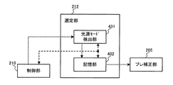
1.2.選定部
図2に、選定部の第1の詳細な構成例を示す。選定部212は、撮像部検出部401、記憶部402(記録部)を含む。撮像部検出部401は、記憶部402と双方向に接続している。撮像部検出部401は、ブレ補正部205へ接続している。制御部210は、撮像部検出部401、記憶部402と双方向に接続している。
1.2. Selection Unit FIG. 2 shows a first detailed configuration example of the selection unit. The
撮像部検出部401は、撮像素子制御部217からの情報に基づいて、内視鏡装置に装着された撮像部102の撮像部IDを検出する。そして選定部212は、撮像部IDに対応するブレ補正IDを記憶部402から読み出し、読み出したブレ補正IDをブレ補正部205へ転送する。
The imaging
ブレ補正部205は、制御部210による制御に基づいて、A/D変換部204からの撮像画像と選定部212からのブレ補正IDを用いて、ブレ補正を行う。具体的にはブレ補正部205は、A/D変換部204からの現在フレームの撮像画像及び画像記憶部214からの過去フレームの撮像画像を所定サイズのブロック領域に分割し、公知のテンプレートマッチング処理により動き量(例えば動きベクトル)を検出する。ブレ補正部205は、全ブロック領域の動き量を加算平均して現在フレームのグローバル動き量を算出する。そしてブレ補正部205は、算出したグローバル動き量に基づいて、A/D変換部204からの現在フレームの撮像画像に対してブレ補正を行う。
The
より具体的には、ブレ補正部205は、現在フレームの撮像画像に対してトリミング領域を設定する。このときブレ補正部205は、算出したグローバル動き量だけトリミング領域を移動させ、そのトリミング領域をトリミングして出力することで、電子ブレ補正を行う。
More specifically, the
1.3.ブレ補正部
図3に、ブレ補正部の第1の詳細な構成例を示す。ブレ補正部205は、補間部301、輝度算出部302、分割部303、動き量検出部304、補正部305、ブロック領域設定部306(ブロック領域特定部)、検出領域設定部307(検出領域特定部)を含む。
1.3. Shake Correction Unit FIG. 3 shows a first detailed configuration example of the shake correction unit. The
選定部212は、輝度算出部302及び検出領域設定部307に接続している。A/D変換部204は、補間部301、輝度算出部302、分割部303、動き量検出部304、補正部305を介して、画像処理部207へ接続している。ROM209は、輝度算出部302、分割部303、ブロック領域設定部306及び検出領域設定部307へ接続している。ブロック領域設定部306は、分割部303へ接続している。検出領域設定部307は、ブロック領域設定部306及び動き量検出部304へ接続している。輝度算出部302は、画像記憶部214へ接続している。補間部301は、輝度算出部302及び補正部305へ接続している。画像記憶部214は、動き量検出部304へ接続している。制御部210は、補間部301、輝度算出部302、分割部303、動き量検出部304、補正部305、ブロック領域設定部306、検出領域設定部307と双方向に接続している。
The
例えば、撮像素子203は原色単板のセンサーであり、原色単板の画像を取得する。この場合、補間部301は、制御部210による制御に基づいて、A/D変換部204からの原色単板の現フレームの撮像画像に対して公知のベイヤ補間処理(ベイヤ画像からRGB3板画像への変換処理)を行う。補間部301は、補間後のRGB3板画像を輝度算出部302へ転送する。
For example, the
輝度算出部302は、制御部210による制御に基づいて、RGB3板の撮像画像を用いて輝度値Y(x,y)を算出する(下式(1))。輝度算出部302は、算出後の輝度値Y(x,y)を分割部303と画像記憶部214へ転送する。この画像記憶部214に保存されている輝度画像(輝度値による画像)は、過去フレームの輝度画像として時系列的に次のフレームの輝度画像のブレ補正に用いられる。具体的には、時系列的に輝度画像を取り込むたびに、画像記憶部214にある時間的に一番古い輝度画像を更新し、現在フレームの輝度画像を保存する。
Y(x,y)=a1*R(x,y)+b1*G(x,y)+c1*B(x,y)
(1)
Based on the control by the
Y (x, y) = a1 * R (x, y) + b1 * G (x, y) + c1 * B (x, y)
(1)
ここで、上式(1)においてx,yは画像中の画素に対応する横軸、縦軸の座標である。例えば横軸は水平走査線に平行な軸であり、縦軸は横軸に直交する軸である。Y(x,y)は輝度値であり、R(x,y),G(x,y),B(x,y)はRGB3板の画素値である。a1,b1,c1は輝度値を算出するための所定係数である。 Here, in the above formula (1), x and y are the coordinates of the horizontal axis and the vertical axis corresponding to the pixels in the image. For example, the horizontal axis is an axis parallel to the horizontal scanning line, and the vertical axis is an axis orthogonal to the horizontal axis. Y (x, y) is a luminance value, and R (x, y), G (x, y), and B (x, y) are pixel values of the RGB3 plate. a1, b1, and c1 are predetermined coefficients for calculating the luminance value.
なお、上記では上式(1)により輝度値を求める場合について説明したが、本実施形態ではこれに限定されず、G板により撮像されたG画像を輝度画像とする構成にしてもよい。 In addition, although the case where a luminance value is calculated | required by said Formula (1) was demonstrated above, in this embodiment, it is not limited to this, You may make it the structure which makes G image imaged with G board a luminance image.
検出領域設定部307は、動き量検出用の検出領域のサイズを設定する。具体的には、検出領域設定部307は、選定部212からのブレ補正IDに対応する検出領域サイズをROM209から読み出し(抽出し)、読み出したサイズを動き量検出部304へ転送する。また検出領域設定部307は、制御部210による制御に基づいて、選定部212からのブレ補正IDをブロック領域設定部306へ転送する。
The detection
ブロック領域設定部306は、ブロック領域分割用のブロック領域のサイズを設定する。具体的には、ブロック領域設定部306は、検出領域設定部307からのブレ補正IDに対応するブロック領域サイズをROM209から読み出して分割部303へ転送する。
The block
分割部303は、ブロック領域設定部306からのブロック領域サイズの情報に基づいて、輝度算出部302からの現在フレームの輝度画像を複数のブロック領域に分割する。分割部303は、分割処理後の輝度画像を動き量検出部304へ転送する。
The dividing
動き量検出部304は、検出領域設定部307からの検出領域サイズの情報に基づいて、分割部303からの分割処理後の現在フレームの輝度画像を用い、画像記憶部214からの過去フレームの輝度画像に対して公知のテンプレートマッチング処理(SSD或はSAD)を行う。
Based on the detection area size information from the detection
補正部305は、動き量検出部304からのマッチングの情報に基づいて、現在フレームの撮像画像に対して公知のブレ補正処理を行い、処理後の画像を画像処理部207へ転送する。
The
図4に、テンプレートマッチングの例を示す。図4では、画像サイズを縦幅HEIGHTと横幅WIDTHにより表す。分割部303は、ブロック領域のサイズ情報に基づいて、輝度算出部302からの現在フレームの輝度画像を複数のブロックに分割する。ブロック領域のサイズ情報は、ブロック領域の縦幅B_heightと横幅B_widthである。
FIG. 4 shows an example of template matching. In FIG. 4, the image size is represented by the vertical width HEIGHT and the horizontal width WIDTH. The dividing
動き量検出部304は、制御部210による制御に基づいて、ブロック中心点SB(x,y)をブロック代表点としてブロック領域の動き量を検出する。このとき、動き量検出部304は、注目ブロック領域と検出領域のテンプレートマッチング処理を行う。注目ブロック領域とは、順次テンプレートマッチング処理される複数のブロック領域の中の、現在処理対象となっているブロック領域である。検出領域は、検出領域設定部307からのサイズ情報により設定される。サイズ情報は、検出領域の開始座標SA(x,y)と終了座標EA(x,y)であり、検出領域の縦幅と横幅は、それぞれブロック領域の縦幅と横幅より大きい。動き量検出部304は、全ブロック領域のテンプレートマッチングが終了後、全ブロック領域の動き量を加算平均して現在フレームのグローバル動き量を算出し、そのグローバル動き量を補正部305へ転送する。
Based on the control by the
ここで、動き量とは、撮像画像における被写体の動きを表す量であり、例えば被写体の動きの撮像画像上での方向や距離である。動き量は、2フレーム間における被写体の動きを表す量であってもよく、複数フレームに渡る被写体の動きを表す量であってもよい。例えば動き量は撮像画像における被写体の動きベクトルである。 Here, the motion amount is an amount representing the motion of the subject in the captured image, and is, for example, the direction or distance of the motion of the subject on the captured image. The amount of movement may be an amount that represents the movement of the subject between two frames, or may be an amount that represents the movement of the subject across a plurality of frames. For example, the amount of motion is a motion vector of the subject in the captured image.
補正部305は、動き量検出部304からのグローバル動き量に基づいて、補間部301からの現在フレームの撮像画像に対して公知のブレ補正処理を行う。例えば、補正部305は、現在フレームのグローバル動き量(方向、距離)に基づいて、現在フレームの撮像画像のRGB3板全画素(R(I,J)、G(I,J)、B(I,J)、Iは画素の横軸座標、Jは画素の縦軸座標)に対してブレ補正処理を行う(下式(2))。
I’=I+moveX,
J’=J+moveY (2)
The
I ′ = I + moveX,
J '= J + moveY (2)
ここで、I’はブレ補正後の横軸座標であり、J’はブレ補正後の縦軸座標である。moveXは現在フレームの撮像画像の横軸に対応するグローバル動き量である。moveXは、水平方向において被写体が移動した画素数であり、座標Iの正方向(例えば右方向)へ動く場合、正の画素数で表され、座標Iの負方向(例えば左方向)へ動く場合、負の画素数で表される。moveYは、垂直方向において被写体が移動した画素数であり、座標Jの正方向(例えば下方向)へ動く場合、正の画素数で表され、座標Jの負方向(例えば上方向)へ動く場合、負の画素数で表される。 Here, I 'is the horizontal axis coordinate after blur correction, and J' is the vertical axis coordinate after blur correction. moveX is a global motion amount corresponding to the horizontal axis of the captured image of the current frame. moveX is the number of pixels that the subject has moved in the horizontal direction. When the object moves in the positive direction (for example, the right direction) of the coordinate I, it is represented by the number of positive pixels and moves in the negative direction of the coordinate I (for example, the left direction). , Expressed as a negative number of pixels. moveY is the number of pixels the subject has moved in the vertical direction. When moving in the positive direction (for example, downward) of the coordinate J, it is represented by the number of positive pixels and when moving in the negative direction of the coordinate J (for example, upward). , Expressed as a negative number of pixels.
本実施形態では、撮像素子203による撮像画像の画像サイズが異なる場合に対応して、異なるブレ補正処理を行うことが特徴となっている。例えば、異なる画像サイズに対応する撮像素子により同じ画角で撮像された画像は、画像サイズに応じて解像力が異なるため、画像の見え方が異なる。画像サイズの大きい撮像画像は、画像サイズの小さい撮像画像に比べて解像力が高い。そのため、異なる画像サイズと同じ画角において同一動き量を検出する場合に、同じ検出領域サイズとブロック領域サイズにより動き量を検出すると、解像力の違いが原因で動き量の検出精度に差が出る可能性が高い。
The present embodiment is characterized in that different blur correction processing is performed corresponding to the case where the image sizes of the images captured by the
この課題を解決するため、本実施形態では、撮像素子203から出力された撮像画像の画像サイズに対応して、動き量を検出するための検出領域サイズとブロックサイズを設定する。具体的には、画像サイズに比例して、検出領域サイズとブロックサイズを設定する。例えば、同じ画角で撮像する場合、1024x1024画素の画像サイズに対応してブロックサイズを32x32画素に設定し、検出領域サイズを64x64画素に設定する。また、256x256の画像サイズに対応して、ブロックサイズを8x8画素に設定し、検出領域サイズを16x16画素に設定する。このようにすれば、相対的にほぼ同じ画角で動き量を検出することができるため、動き量の検出精度を同等にできる。
In order to solve this problem, in the present embodiment, a detection area size and a block size for detecting the amount of motion are set corresponding to the image size of the captured image output from the
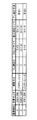
より具体的には、図5に示すように、上述の撮像部IDと画像サイズの対応関係、及び撮像部IDとブレ補正IDの対応関係をテーブル化し、そのテーブルを図2の記憶部402に保存する。また、ブレ補正IDとブロック領域サイズの対応関係、及びブレ補正IDと検出領域サイズの対応関係をテーブル化し、そのテーブルを図1のROM209に保存する。
More specifically, as shown in FIG. 5, the correspondence relationship between the imaging unit ID and the image size and the correspondence relationship between the imaging unit ID and the blur correction ID are tabulated, and the table is stored in the
以上のように、画像サイズに応じて検出領域サイズやブロックサイズを適応的に設定することで、撮像画像における動き量の検出精度を向上できる。これにより、ブレ補正の精度を高めることができ、医師の診断能力を向上することができる。 As described above, the detection accuracy of the motion amount in the captured image can be improved by adaptively setting the detection area size and the block size according to the image size. Thereby, the accuracy of blur correction can be increased, and the diagnostic ability of the doctor can be improved.
1.4.第1の変形例
上記のように、同じ画角の場合、撮像画像の画像サイズが小さければ小さいほど解像力が劣る。これが原因で検出領域サイズ、ブロックサイズを適応的に変更して対応しても動き量を正しく検出できない場合がある。そこで本実施形態では、動き量を検出する前に、画像からエッジ情報を検出し、検出したエッジ情報を用いて強調処理を行う構成にしてもよい。以下では、このような本実施形態の第1の変形例について説明する。
1.4. First Modification As described above, in the case of the same angle of view, the smaller the image size of the captured image, the lower the resolution. For this reason, even if the detection area size and the block size are adaptively changed, the amount of motion may not be detected correctly. Therefore, in the present embodiment, edge information may be detected from the image before the amount of motion is detected, and enhancement processing may be performed using the detected edge information. Below, the 1st modification of such this embodiment is demonstrated.
図6に、ブレ補正部の第2の詳細な構成例を示す。ブレ補正部205は、補間部301、輝度算出部302、エッジ強調処理部311、分割部303、動き量検出部304、補正部305、ブロック領域設定部306、検出領域設定部307を含む。
FIG. 6 shows a second detailed configuration example of the blur correction unit. The
選定部212は、輝度算出部302、エッジ強調処理部311及び検出領域設定部307に接続している。A/D変換部204は、補間部301、輝度算出部302、エッジ強調処理部311、分割部303、動き量検出部304、補正部305を介して、画像処理部207へ接続している。ROM209は、輝度算出部302、エッジ強調処理部311、分割部303、ブロック領域設定部306及び検出領域設定部307へ接続している。補間部301は、輝度算出部302及び補正部305へ接続している。検出領域設定部307は、ブロック領域設定部306を介して分割部303へ接続している。検出領域設定部307は、動き量検出部304へ接続している。輝度算出部302は、画像記憶部214へ接続している。画像記憶部214は、動き量検出部304へ接続している。制御部210は、補間部301、輝度算出部302、エッジ強調処理部311、分割部303、動き量検出部304、補正部305、ブロック領域設定部306、検出領域設定部307と双方向に接続している。
The
以下では、図3で上述の構成要素と同一の構成要素については同一の符号を付して適宜説明を省略し、上述の構成要素と異なる部分のみを説明する。 In the following, the same components as those described above with reference to FIG. 3 are denoted by the same reference numerals, description thereof will be omitted as appropriate, and only the portions different from those described above will be described.
図7に、エッジ強調処理部の詳細な構成例を示す。エッジ強調処理部311は、エッジ検出部501、強度制御部502、強調処理部503、加算部504を含む。
FIG. 7 shows a detailed configuration example of the edge enhancement processing unit. The edge
輝度算出部302は、エッジ検出部501、強調処理部503、加算部504を介して分割部303へ接続している。選定部212は、強度制御部502へ接続している。ROM209は、強度制御部502を介して強調処理部503へ接続している。輝度算出部302は加算部504へ接続している。制御部210は、エッジ検出部501、強度制御部502、強調処理部503及び加算部504と双方向に接続している。
The
エッジ検出部501は、制御部210による制御に基づいて、輝度算出部302からの現在フレーム及び過去フレームの輝度画像に対して公知のラプラシアンフィルタを適用してエッジデータを検出し、そのエッジデータを強調処理部503へ転送する。
Based on the control by the
強度制御部502は、選定部212からのブレ補正IDに対応する強度ウェート係数をROM209から読み出し、その強度ウェート係数をエッジ強調処理部311へ転送する。ROM209には、エッジ強調用の強度ウェート係数があらかじめ保存されている。本実施形態では、異なるブレ補正IDに対応して、異なる強度ウェート係数が設定される。
The
より具体的には、上述のように同じ画角の場合、撮像画像の画像サイズが小さければ小さいほど解像力が劣る。これに対応するために、強度制御部502は、画像サイズに応じた強度ウェート係数を設定する。例えば、画像サイズが小さいほど強度ウェート係数を大きく設定するように制御する。
More specifically, in the case of the same angle of view as described above, the smaller the image size of the captured image, the lower the resolution. In order to cope with this, the
強調処理部503は、エッジデータに対して強度ウェート係数を用いて強調処理を行い、強調後のエッジデータを加算部504へ転送する。加算部504は、強調後のエッジデータを、輝度算出部302からの輝度画像に加算し、加算後の輝度画像を分割部303へ転送する。
The
なお、本実施形態ではレンズ系201のMTFに応じて強度ウェート係数を設定してもよい。具体的には、同じ画像サイズをもつ撮像素子により同じ画角で撮像された画像では、レンズ系201のMTFの特性が異なることによって、解像力が異なる。この場合、レンズ系201のMTFの特性に合わせて適応的にエッジ強調の強度を調整することで、テンプレートマッチング処理の精度を向上できる。例えば、レンズ系201のMTFの特性が悪い場合、撮像画像の解像力が劣るため、強度ウェート係数を大きく設定する。一方、レンズ系201のMTFの特性が良い場合、撮像画像の解像力が高いため、強度ウェート係数を小さく設定する。
In the present embodiment, the intensity weight coefficient may be set according to the MTF of the
以上のように、画像サイズやMTFに応じて適応的にエッジ強調の強度を調整することで、撮像画像のコントラストを向上できる。これにより、動き量の検出精度を高めることが可能となる。 As described above, the contrast of the captured image can be improved by adaptively adjusting the edge enhancement strength according to the image size and MTF. Thereby, it becomes possible to improve the detection accuracy of the amount of motion.
1.5.第2の変形例
次に、本実施形態の第2の変形例について説明する。第2の変形例では、撮像素子203のセンサー配列構成が異なる場合、動き量を検出する手法を適応的に変更する。例えば図5に示すように、プログレッシブ方式とインターレース方式に対応して、ブレ補正手法を手法1と手法2に切り替える。
1.5. Second Modification Example Next, a second modification example of the present embodiment will be described. In the second modification, when the sensor array configuration of the
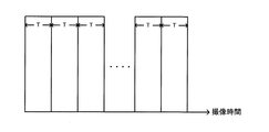
まず、撮像素子203がインターレース補色単板である場合について説明する。図8に、インターレース補色単板(Mg,G,Cy,Ye)の画像信号の構成例を示す。撮像素子203により撮像された画像は、奇数ラインから構成される奇数フィールドの画像信号と、偶数ラインから構成される偶数フィールドの画像信号と、により構成される。そして、A/D変換部204には、奇数フィールドの画像信号と偶数フィールドの画像信号が時系列に交互に入力される。補間部301は、制御部210による制御に基づいて、奇数フィールドの画像信号と偶数フィールドの画像信号のそれぞれに対して、公知の補間処理を行う。輝度算出部302は、奇数フィールドの画像信号と偶数フィールドの画像信号のそれぞれを、輝度信号と色差信号に変換する。
First, the case where the
図9に示すように、奇数フィールドの画像信号と偶数フィールドの画像信号は、周期Tの間隔で時系列的に交互に撮像されている。動き量検出部304は、奇数フィールドにおける被写体の動き量と、偶数フィールドにおける被写体の動き量を、時系列的に交互に検出する。即ち、動き量検出部304は、現在の奇数フィールドの輝度信号と、過去の奇数フィールドの輝度信号から、奇数フィールドの動き量を検出する。また、現在の偶数フィールドの輝度信号と、過去の偶数フィールドの輝度信号から、偶数フィールドの動き量を検出する。ブレ補正部205は、奇数フィールドの動き量を用いて、現在の奇数フィールドの画像信号に対してブレ補正処理を行う。また、偶数フィールドの動き量を用いて、現在の偶数フィールドの画像信号に対してブレ補正処理を行う。
As shown in FIG. 9, the odd-numbered field image signal and the even-numbered field image signal are alternately captured in time series at intervals of a period T. The motion
次に、撮像素子203がRGB3板である場合について説明する。この場合、各画素にR,G,B3つの画素値が撮像される。輝度算出部302は、その画素値を用いて上式(1)により各画素の輝度値Y(x,y)を算出する。動き量検出部304は、算出された輝度値を用いて動き量を算出し、ブレ補正部205は、その動き量によりブレ補正処理を行う。なお、各画素のG画素値を輝度値として動き量を算出してブレ補正処理を行う構成にしてもよい。
Next, the case where the
次に、撮像素子203が2板である場合について説明する。図10に、2板撮像素子により撮像される画像信号の例を示す。図10に示すように、第1撮像素子により撮像された画像には、R、Bの画素値(R画像信号、B画像信号)が配列される。R画素とB画素は、列ごとに交差する構成となっている。第2撮像素子により撮像された画像は、全画素にG画素値(G画像信号)が配列されたG画像である。この場合、補間部301は、制御部210による制御に基づいて、下式(3)に示す補間処理により、全画素にR画素値が配列されたR画像と、全画素にB画素値が配列されたB画像を生成する。
R(x,y) =(R(x−1,y)+R(x+1,y))/2,
B(x+1,y)=(B(x,y)+B(x+2,y))/2 (3)
Next, a case where the
R (x, y) = (R (x-1, y) + R (x + 1, y)) / 2
B (x + 1, y) = (B (x, y) + B (x + 2, y)) / 2 (3)
ここで、x,yは撮像画像の画素に対応する横軸、縦軸の座標である。R(x,y)、B(x+1,y)は、補間後の画素値である。R(x−1,y)、R(x+1,y)、B(x,y)、B(x+2,y)は、補間前の画素値である。 Here, x and y are coordinates on the horizontal and vertical axes corresponding to the pixels of the captured image. R (x, y) and B (x + 1, y) are pixel values after interpolation. R (x-1, y), R (x + 1, y), B (x, y), and B (x + 2, y) are pixel values before interpolation.
さて、内視鏡装置においてブレ補正を行う場合、例えば撮像部の特性や観察モード、観察者の熟練度等の観察状態に応じて、ブレ発生の頻度やブレの強度が異なるという課題がある。 When performing blur correction in an endoscope apparatus, there is a problem that the frequency of blur occurrence and the intensity of blur differ depending on the observation state such as the characteristics of the imaging unit, the observation mode, the skill level of the observer, and the like.
この点、本実施形態によれば、図1に示すように内視鏡装置は撮像部102と選定部212とブレ補正部205を含む。撮像部102は撮像光学系(レンズ系201)と撮像素子203を有し、撮像画像の撮像を行う。選定部212は、複数のブレ補正用パラメータ情報の中から、使用するブレ補正用パラメータ情報を、撮像部102の観察状態に基づいて選定する。ブレ補正部205は、選定されたブレ補正用パラメータ情報に基づいて、撮像画像のブレを補正する。
In this regard, according to the present embodiment, as shown in FIG. 1, the endoscope apparatus includes an
例えば本実施形態では、複数のブレ補正用パラメータ情報として複数のブレ補正IDが記憶されている。そして、観察状態に対応するブレ補正IDが選定され、そのブレ補正IDにより指定されるパラメータを用いて電子ブレ補正が行われる。 For example, in the present embodiment, a plurality of blur correction IDs are stored as a plurality of blur correction parameter information. Then, a shake correction ID corresponding to the observation state is selected, and electronic shake correction is performed using parameters specified by the shake correction ID.
このようにすれば、観察状態に応じて最適なブレ補正用のパラメータを設定できる。これにより、種々のブレ発生の頻度やブレの強度に適応したブレ補正が可能となり、被写体の視認性を向上できるため、病変の見落としや診察負担を軽減できる。 In this way, it is possible to set an optimum blur correction parameter according to the observation state. As a result, blur correction adapted to the frequency of occurrence of blur and the intensity of blur can be performed, and the visibility of the subject can be improved, so that the oversight of the lesion and the medical examination burden can be reduced.
ここで、ブレ補正用パラメータ情報とは、ブレ補正に用いられるパラメータを指定する情報である。また、フレーム内のブレを抑制するブレ抑制制御や、照明光の光量を調整する光量制御等の、ブレ補正に関連するパラメータ情報も、適宜ブレ補正用パラメータ情報と呼ぶ。ブレ補正用パラメータ情報は、パラメータに対応するID等の情報であってもよいし、パラメータそのものであってもよい。 Here, the blur correction parameter information is information for designating parameters used for blur correction. Also, parameter information related to blur correction, such as blur suppression control for suppressing blur in a frame and light amount control for adjusting the amount of illumination light, is also referred to as blur correction parameter information as appropriate. The blur correction parameter information may be information such as an ID corresponding to the parameter, or the parameter itself.
また、観察状態とは、内視鏡装置により撮像を行う状態や状況である。例えば、上述のような撮像画像の画像サイズ(画素数)や、撮像光学系のMTF等により表される撮像画像の状態である。あるいは、インターレース方式等の撮像方式である。あるいは、後述するように、通常観察や拡大観察等の観察モード、スクリーニングモードや精査モード等の観察モード、医師の熟練度に対応する観察者モードである。 The observation state is a state or situation in which imaging is performed by the endoscope apparatus. For example, it is the state of the captured image represented by the image size (number of pixels) of the captured image as described above, the MTF of the imaging optical system, or the like. Alternatively, an imaging method such as an interlace method is used. Or, as will be described later, an observation mode such as normal observation or magnified observation, an observation mode such as a screening mode or a close examination mode, or an observer mode corresponding to the skill level of a doctor.
また、本実施形態では、内視鏡装置は複数種類の撮像部102を着脱可能である。図2に示すように、選定部212は、内視鏡装置に装着された撮像部102の種類を検出する撮像部検出部401と、複数種類の撮像部102に対応する複数のブレ補正用パラメータ情報(複数のブレ補正ID)を記憶する記憶部402と、を有する。選定部212は、記憶された複数のパラメータ情報の中から、装着された撮像部102の種類に応じたブレ補正用パラメータ情報(ブレ補正ID)を選定する。
In the present embodiment, the endoscope apparatus can attach and detach a plurality of types of
具体的には、図3に示すように内視鏡装置はブロック領域設定部306と分割部303と検出領域設定部307とを含む。ブロック領域設定部306は、撮像画像に対して複数のブロック領域を設定する。分割部303は、撮像画像を、設定された複数のブロック領域に分割する。検出領域設定部307は、撮像画像において動き量を検出する対象となる領域を設定する。図5に示すように、選定部212は、ブロック領域のサイズ及び検出対象領域のサイズに対応するブレ補正用パラメータ情報を、装着された撮像部102の撮像素子203のサイズ(画素数)に応じて選定する。図4に示すように、動き量検出部304は、選定されたブレ補正用パラメータ情報に対応するサイズ(B_width、B_height、SA(x,y)、EA(x,y))のブロック領域及び検出対象領域を用いて、動き量を検出する。
Specifically, as shown in FIG. 3, the endoscope apparatus includes a block
このようにすれば、種々の撮像部が付け替えられた場合であっても、撮像部に応じて適切なブロック領域と検出対象領域を設定できる。即ち、撮像部の仕様によって画像の画素数は異なっており、同じ領域サイズを設定すると、画像サイズに対する相対的な領域サイズ(画角)が一定にならない。この点、本実施形態によれば、領域サイズを適応的に設定して領域の画角を一定にできる。 In this way, even when various image pickup units are replaced, an appropriate block region and detection target region can be set according to the image pickup unit. That is, the number of pixels of the image differs depending on the specifications of the imaging unit. If the same region size is set, the region size (view angle) relative to the image size is not constant. In this regard, according to the present embodiment, the field size can be set adaptively to make the field angle of the area constant.
また本実施形態では、図3に示すように、ブレ補正部205は、撮像画像における被写体の動き量を検出する動き量検出部304を含む。選定部212は、装着された撮像部102の撮像方式に応じてブレ補正用パラメータ情報を選定する。動き量検出部304は、選定されたブレ補正用パラメータ情報に対応する検出手法により動き量を検出する。
In the present embodiment, as shown in FIG. 3, the
具体的には、撮像方式は、単板インターレース方式、単板プログレッシブ方式、2板撮像素子方式、又は3板撮像素子方式である。 Specifically, the image pickup method is a single plate interlace method, a single plate progressive method, a two plate image pickup device method, or a three plate image pickup device method.
例えば図10に示すように、撮像部102は、G画像の撮像を行う第1の撮像素子と、R画像とB画像の撮像を行う第2の撮像素子と、を有する(2板撮像方式)。この場合、選定部212は、G画像から動き量を検出するブレ補正用パラメータ情報を選定する。
For example, as illustrated in FIG. 10, the
又は撮像部102は、G画像の撮像を行う第1の撮像素子と、R画像の撮像を行う第2の撮像素子と、B画像の撮像を行う第3の撮像素子と、を有してもよい(3板撮像方式)。この場合、選定部212は、G画像とR画像とB画像に基づく輝度画像から動き量を検出するブレ補正用パラメータ情報を選定する。
Alternatively, the
又は図8に示すように、撮像部102は、インターレース方式の撮像を行ってもよい。この場合、図9に示すように、選定部212は、奇数水平走査線の画像信号に基づいて第1の動き量を検出し、偶数水平走査線の画像信号に基づいて第2の動き量を検出するブレ補正用パラメータ情報を選定する。ブレ補正部205は、第1の動き量に基づいて奇数水平走査線の画像信号のブレ補正を行い、第2の動き量に基づいて偶数水平走査線の画像信号のブレ補正を行う。
Alternatively, as illustrated in FIG. 8, the
又は撮像部102は、R画像とG画像とB画像を時系列に撮像する面順次方式の撮像を行ってもよい。この場合、選定部212は、R画像に基づいて第1の動き量を検出し、G画像に基づいて第2の動き量を検出し、B画像に基づいて第3の動き量を検出するブレ補正用パラメータ情報を選定する。ブレ補正部205は、第1の動き量に基づいてR画像のブレ補正を行い、第2の動き量に基づいてG画像のブレ補正を行い、第3の動き量に基づいてB画像のブレ補正を行う。
Alternatively, the
以上のようにすれば、撮像部102の撮像方式に応じた適切な検出手法によりブレ補正を行うことができる。即ち、内視鏡装置には診察部位等に応じて種々の撮像部102が着脱され、その撮像方式に依って撮像画像の形式や特性が異なっている。この点、本実施形態によれば、撮像部102に記憶された撮像部ID等の情報を読み出し、その情報に基づいて、種々の撮像画像の形式や特性に対応したブレ補正処理を設定できる。
As described above, blur correction can be performed by an appropriate detection method according to the imaging method of the
また本実施形態では、図6に示すように、撮像画像に対してエッジ強調処理を行うエッジ強調処理部311を含む。選定部212は、装着された撮像部102の撮像素子203が第1のサイズである場合、エッジ強調処理の第1の強度に対応するブレ補正用パラメータ情報を選定する。撮像素子203が第1のサイズよりも小さい第2のサイズである場合に、第1の強度よりも強い第2の強度に対応するブレ補正用パラメータ情報を選定する。エッジ強調処理部311は、選定されたブレ補正用パラメータ情報に対応する強度でエッジ強調処理を行う。
In the present embodiment, as shown in FIG. 6, an edge
このようにすれば、撮像素子203のサイズに応じた強度でエッジ強調処理を行い、処理後の画像によりブレ補正できる。これにより、撮像素子203の画素数が少なく、画像信号の解像度が低い場合であっても、エッジ強調処理によりマッチング精度を向上でき、ブレ補正の精度を向上できる。
In this way, edge enhancement processing is performed with an intensity corresponding to the size of the
ここで、エッジ強調処理の強度とは、元の画像のエッジ成分(例えば高周波成分)の強調度合いである。例えば、元の画像から抽出したエッジ成分を、係数倍して元の画像に加算する場合、強度が大きいほど係数を大きくする。 Here, the strength of edge enhancement processing is the degree of enhancement of edge components (for example, high frequency components) of the original image. For example, when an edge component extracted from an original image is multiplied by a coefficient and added to the original image, the coefficient increases as the strength increases.
2.第2の実施形態
2.1.構成例
次に、第2の実施形態について説明する。第2の実施形態では、観察者モードに応じて適応的にブレ補正を行う。
2. Second Embodiment 2.1. Configuration Example Next, a second embodiment will be described. In the second embodiment, blur correction is adaptively performed according to the observer mode.
図11に、内視鏡装置の第2の構成例を示す。内視鏡装置は、制御装置300、撮像部102を含む。撮像部102は、ライトガイド103、レンズ系201、撮像素子203を含む。制御装置300は、光源部104、A/D変換部204、ブレ補正部205、画像処理部207、表示部208、ROM209、選定部212、画像記憶部214、光源制御部215、レンズ制御部216、撮像素子制御部217、制御部210、外部I/F部211を含む。
FIG. 11 shows a second configuration example of the endoscope apparatus. The endoscope apparatus includes a
選定部212以外は、第1の実施形態と同一である。なお以下では、第1の実施形態と同一の構成要素については同一の符号を付して適宜説明を省略し、第1の実施形態の構成要素と異なる部分のみを説明する。
Except for the
撮像部の先端部がランダムにブレている場合、ブレ補正により撮像画像のブレを抑制する効果があるが、撮像部の先端部が例えば医師の操作により一定方向に動いている場合、ブレ補正により表示画像の遅延が大きくなる可能性がある。 When the tip of the imaging unit is randomly blurred, there is an effect of suppressing blur of the captured image by blur correction, but when the tip of the imaging unit is moving in a certain direction by, for example, a doctor's operation, There is a possibility that the delay of the display image becomes large.
医療用内視鏡装置により体腔内の臓器を診察又は治療する場合、病変部を探すスクリーニング観察と、病変部や病変部と疑われる領域を精査する精査観察が行われる。経験が豊かな医師がスクリーニング診察を行う場合、内視鏡スコープの操作(挿入、抜去、回転等)によるブレが小さいため、病変部を見逃す確率が低い。また精査を行う場合、経験豊富な医師は注目診察領域に照準してブレを最小限に抑えることができるため、正確かつ素早く病変部を判定することが可能である。一方、経験が少ない医師がスクリーニング診察を行う場合、内視鏡スコープの操作によるブレが大きいため、病変部を見逃す確率が高い。また精査を行う場合、経験が少ない医師は注目診察領域に照準できずブレを有効に抑制できないため、診断に時間がかかる可能性が高い。 When a medical endoscopic apparatus examines or treats an organ in a body cavity, screening observation for finding a lesioned part and scrutiny observation for examining a lesioned part or a region suspected to be a lesioned part are performed. When an experienced doctor conducts a screening examination, since the blur due to the operation (insertion, removal, rotation, etc.) of the endoscope is small, the probability of missing a lesion is low. In addition, when conducting a detailed examination, an experienced doctor can aim at the attention examination area and minimize blurring, so that it is possible to accurately and quickly determine a lesion. On the other hand, when a doctor who has little experience conducts a screening examination, there is a high probability of missing a lesion because blurring due to the operation of the endoscope scope is large. In addition, when a close examination is performed, a doctor who has little experience cannot aim at the attention examination area and cannot effectively suppress blurring, and thus it is likely to take time for diagnosis.
そこで本実施形態では、医師の経験に応じて異なるブレ補正処理を行う。即ち、内視鏡スコープの操作に熟練した医師の場合、操作によるブレが小さいため、後述するように動き量検出における検出期間を短く設定し、撮像画像の表示遅延が発生しないようにする。一方、内視鏡スコープの操作経験が少ない医師の場合、操作によるブレが大きいため、動き量検出における検出期間を長く設定し、表示遅延とトレードオフにする。 Therefore, in this embodiment, different blur correction processing is performed according to the experience of the doctor. That is, in the case of a doctor who is skilled in the operation of the endoscope scope, since the shake due to the operation is small, the detection period in the motion amount detection is set short as will be described later, so that the display delay of the captured image does not occur. On the other hand, in the case of a doctor who has little experience in operating an endoscope scope, since the blur due to the operation is large, the detection period in the motion amount detection is set to be long, and the display delay is traded off.
図12に、選定部の第2の詳細な構成例を示す。選定部212は、観察者モード検出部、記憶部402を含む。観察者モード検出部は、記憶部402を介してブレ補正部205へ接続している。制御部210は、観察者モード検出部、記憶部402と双方向に接続している。
FIG. 12 shows a second detailed configuration example of the selection unit. The
記憶部402には、各医師に割り当てられた医師IDと、各医師の経験に対応するブレ補正IDが、事前に保存される。医師IDとブレ補正IDは1対1(又は複数対1)に対応している。医師の診察経験に応じて、適時に医師IDに対応するブレ補正IDを登録、修正できる。
The
医師は、診察開始時に、外部I/F部211を介して自分の医師IDを入力する。観察者モード検出部411は、医師IDに対応するブレ補正IDを記憶部402から読み出し、そのブレ補正IDをブレ補正部205へ転送する。このようにして、医師の熟練度に応じた観察者モードが設定され、設定された観察者モードに応じたブレ補正が行われる。
The doctor inputs his / her doctor ID via the external I /
ブレ補正部205は、ブレ補正IDに基づいてブレ補正処理を行う。例えば、ブレ補正部205は、経験豊富な医師の場合にはブレ補正処理をバイパスして行わず、経験が少ない医師の場合にはブレ補正を行う。
The
なお、本実施形態はこれに限定されない。例えば、経験豊富な医師の場合、強いブレ補正を行ってもよい。即ち、ブレ補正部205は、現在フレームの撮像画像と過去1フレームの撮像画像を用いて動き量を検出し、ブレ補正処理を行ってもよい。一方、経験が少ない医師の場合、弱いブレ補正を行ってもよい。即ち、ブレ補正部205は、現在フレームの撮像画像と過去複数フレームでの撮像画像を用いて各フレーム間動き量を検出し、その複数のフレーム間動き量を積分加算した動き量に基づいてブレ補正用のブレ量を算出し(下式(4))、ブレ補正を行ってもよい。
BlurX=moveX−moveXav,
BlurY=moveY−moveYav,
moveXav’=(moveXav+moveX)/2,
moveYav’=(moveYav+moveY)/2 (4)
Note that the present embodiment is not limited to this. For example, in the case of an experienced doctor, strong blur correction may be performed. That is, the
BlurX = moveX-moveXav,
BlurY = moveY-moveYav,
moveXav ′ = (moveXav + moveX) / 2
moveYav ′ = (moveYav + moveY) / 2 (4)
ここで、BlurXは、現在フレームの撮像画像の横軸に対応するブレ量であり、BlurYは現在フレームの撮像画像の縦軸に対応するブレ量である。moveXは現在フレームの撮像画像の横軸に対応するグローバル動き量であり、moveYは現在フレームの撮像画像の縦軸に対応するグローバル動き量である。moveXavは過去フレームの撮像画像の横軸に対応する積算平均グローバル動き量であり、moveYavは過去フレームの撮像画像の縦軸に対応する積算平均グローバル動き量である。moveXav’は現在フレームの撮像画像の横軸に対応する積算平均グローバル動き量であり、moveYav’は現在フレームの撮像画像の縦軸に対応する積算平均グローバル動き量である。 Here, BlurX is a blur amount corresponding to the horizontal axis of the captured image of the current frame, and BlurY is a blur amount corresponding to the vertical axis of the captured image of the current frame. moveX is a global motion amount corresponding to the horizontal axis of the captured image of the current frame, and moveY is a global motion amount corresponding to the vertical axis of the captured image of the current frame. moveXav is an integrated average global motion amount corresponding to the horizontal axis of the captured image of the past frame, and moveYav is an integrated average global motion amount corresponding to the vertical axis of the captured image of the past frame. moveXav ′ is an integrated average global motion amount corresponding to the horizontal axis of the captured image of the current frame, and moveYav ′ is an integrated average global motion amount corresponding to the vertical axis of the captured image of the current frame.
このように、時間方向においてランダムな動き量を平均化して算出することで、所定期間内(所定フレーム数)における平均動き量を算出し、その平均動き量を用いてブレ量を算出してブレ補正処理を行う。これにより、スクリーニング観察において急激に一定方向にスコープが移動された場合、積算平均する期間が長いほど表示画像の遅延が大きくなるが、精査観察におけるランダムブレを補正する精度を高めることが可能となる。なお、この手法を精査観察時のみに適用してもよい。 In this way, by calculating an average of random motion amounts in the time direction, an average motion amount within a predetermined period (a predetermined number of frames) is calculated, and using the average motion amount, a blur amount is calculated to calculate a blur amount. Perform correction processing. Thereby, when the scope is suddenly moved in a certain direction in the screening observation, the longer the period of integration averaging, the longer the delay of the display image, but it is possible to improve the accuracy of correcting the random blur in the close examination observation. . Note that this method may be applied only during close observation.
以上によれば、医師の診察経験に応じて適応的にブレ補正処理を行うことができる。これにより、各医師にとって最適な診察環境を提供することが可能になる。 According to the above, it is possible to adaptively perform the blur correction process according to the doctor's examination experience. This makes it possible to provide an optimal examination environment for each doctor.
2.2.変形例
上記実施形態では、医師の診察経験に合わせてブレ補正手法を選定する構成となっているが、本実施形態はこれに限定されず、例えば観察モードに応じてブレ補正手法を選定する構成にしてもよい。以下では、このような本実施形態の変形例について説明する。
2.2. Modification In the above embodiment, the blur correction method is selected in accordance with the doctor's examination experience. However, the present embodiment is not limited to this, for example, the configuration in which the blur correction method is selected according to the observation mode. It may be. Below, the modification of such this embodiment is demonstrated.
図13に、選定部の第3の詳細な構成例を示す。選定部212は、観察モード検出部421、記憶部402を含む。観察モード検出部421は、記憶部402を介してブレ補正部205へ接続している。制御部210は、観察モード検出部421、記憶部402と双方向に接続している。
FIG. 13 shows a third detailed configuration example of the selection unit. The
この変形例では、精査観察やスクリーニング観察等の観察モードに応じてブレ補正を行う。具体的には、記憶部402には、観察モードIDに対応するブレ補正IDが事前に保存されている。観察モードIDは、各観察モードに対応する。例えば、観察モードIDは、医師が診察時に外部I/F部211を介して設定する。観察モード検出部421は、制御部210による制御に基づいて、観察モードIDに対応するブレ補正IDを記憶部402から読み出し、そのブレ補正IDをブレ補正部205へ転送する。
In this modification, blur correction is performed according to an observation mode such as scrutiny observation or screening observation. Specifically, the blur correction ID corresponding to the observation mode ID is stored in the
ブレ補正部205は、選定部212により選定されたブレ補正IDに基づいてブレ補正処理を行う。具体的には、ブレ補正部205は、ブレ補正の強弱レベルをブレ補正IDに応じて複数段階に変更する。観察モードが精査モードの場合、病変部に対して生検する必要があるか否かを判定する必要があるため、強いブレ補正レベルを設定することでブレを抑制し、正確かつ素早く診断できるように制御する。一方、観察モードがスクリーニングモードの場合、操作の動きが速いため、動き量の検出精度が低くなる可能性がある。この場合、正しくブレ補正ができないことが原因で診断の支障になることも否めないため、弱いブレ補正レベルを設定してブレ補正処理を行うように制御する。
The
例えば、ブレ補正レベルが強いほど、動き量検出に用いるフレーム数を多くする。例えば、スクリーニングモードでは、動き量を検出せずブレ補正を行わない。精査モードでは、上式(4)に示す積算平均グローバル動き量を求めるフレーム数をブレ補正レベルの段階に応じて設定する。 For example, the stronger the blur correction level, the greater the number of frames used for motion amount detection. For example, in the screening mode, the amount of movement is not detected and no blur correction is performed. In the scrutinization mode, the number of frames for obtaining the integrated average global motion amount shown in the above equation (4) is set according to the stage of the blur correction level.
以上のように、観察モードに応じて適応的にブレ補正処理を行うことで、観察状態に応じて適切なブレ補正処理を行うことができ、高精度に診断することが可能となる。 As described above, by performing the shake correction process adaptively according to the observation mode, it is possible to perform an appropriate shake correction process according to the observation state, and it is possible to make a diagnosis with high accuracy.
なお、上記実施形態では、観察者モードや観察モードに応じてブレ補正IDが設定される場合を説明したが、本実施形態はこれに限定されない。例えば、医師が診察時に外部I/F部211を介して、自分の好みに合わせて手動でブレ補正IDを選定する構成にしてもよい。例えば、ブレ補正の強弱レベルを複数段階に変更できる構成にして、医師がなるべく動きを抑制して診察を行う必要があると判断した場合、外部I/F部211を介して強いブレ補正レベルに対応するブレ補正IDを選択して診察することが可能である。一方、操作の動きが速い場合、動き量の検出精度が低くなるリスクを抑制するため、外部I/F部211を介して弱いブレ補正レベルに対応するブレ補正IDを選択して診察してもよい。
In the above embodiment, the case where the shake correction ID is set according to the observer mode or the observation mode has been described. However, the present embodiment is not limited to this. For example, a configuration may be adopted in which a doctor manually selects a blur correction ID according to his / her preference via the external I /
以上によれば、内視鏡装置は、被写体を観察する観察モード(観察モードID)を設定する観察モード設定部(例えば、図11の制御部210が含む図示しない観察モード設定部)を含む。図13に示すように、選定部212は、設定された観察モードを検出する観察モード検出部421と、複数の観察モードに対応する複数のブレ補正用パラメータ情報(複数のブレ補正ID)を記憶する記憶部402と、を有する。選定部212は、記憶された複数のブレ補正用パラメータ情報の中から、検出された観察モードに対応するブレ補正用パラメータ情報(ブレ補正ID)を選定する。
As described above, the endoscope apparatus includes an observation mode setting unit (for example, an observation mode setting unit (not shown) included in the
具体的には、記憶部402は、ブレ補正の強弱レベル(上述のように、例えば動き量を積算平均するフレーム数)についてのブレ補正用パラメータ情報を記憶する。選定部212は、スクリーニングモードが検出された場合、第1のレベル(第1のフレーム数)に対応するブレ補正用パラメータ情報を選定する。精査モードが検出された場合、第1のレベルよりも強い第2のレベル(第2のフレーム数)に対応するブレ補正用パラメータ情報を選定する。
Specifically, the
又は記憶部402は、ブレ補正を行うか否かについてのブレ補正用パラメータ情報を記憶してもよい。この場合、選定部212は、スクリーニングモードが検出された場合、ブレ補正を行わないブレ補正用パラメータ情報を選定する。精査モードが検出された場合、ブレ補正を行うブレ補正用パラメータ情報を選定する。
Or the memory |
このようにすれば、観察モードに応じて適切なブレ補正を行うことができる。即ち、スクリーニングモードではブレ補正レベルを弱くすることで、上述のように表示遅延等の影響を最小限にして病変部の探索を行うことができる。精査モードではブレ補正レベルを強くすることで、ランダムなスコープの動きによるブレを抑制して、詳細に病変部を観察できる。 In this way, appropriate blur correction can be performed according to the observation mode. In other words, in the screening mode, by reducing the blur correction level, it is possible to search for a lesioned part while minimizing the influence of display delay or the like as described above. In the scrutinization mode, by increasing the blur correction level, blur due to random scope movement can be suppressed, and the lesion can be observed in detail.
なお観察モードは、上述のようにユーザにより外部I/F部211を介して設定されてもよいし、レンズ系201の拡大率に応じて設定されてもよい。例えば、拡大率が閾値よりも大きい拡大観察では精査モードに設定し、拡大率が閾値より低い通常観察ではスクリーニングモードに設定してもよい。
Note that the observation mode may be set by the user via the external I /
また本実施形態では、内視鏡装置は、内視鏡装置を操作する観察者に応じた観察者モード(医師ID)を設定する観察者モード設定部を含む(例えば、図11の制御部210が含む図示しない観察者モード設定部)。図12に示すように、選定部212は、設定された観察者モードを検出する観察者モード検出部411と、複数の観察者モードに対応する複数のブレ補正用パラメータ情報を記憶する記憶部402と、を有する。選定部212は、記憶された複数のブレ補正用パラメータ情報の中から、検出された観察者モードに対応するブレ補正用パラメータ情報を選定する。
Further, in the present embodiment, the endoscope apparatus includes an observer mode setting unit that sets an observer mode (doctor ID) corresponding to an observer who operates the endoscope apparatus (for example, the
具体的には、記憶部402は、動き量の検出に用いられる撮像画像のフレーム数(上式(4)の積算平均グローバル動き量の積算平均フレーム数)に対応するパラメータ情報を記憶する。選定部212は、第1の観察者モードが検出された場合に、第1のフレーム数に対応するブレ補正用パラメータ情報を選定する。第2の観察者モードが検出された場合に、第1のフレーム数よりも多い第2のフレーム数に対応するブレ補正用パラメータ情報を選定する。
Specifically, the
より具体的には、第2の観察者モードは、第1の観察者モードに対応する観察者よりも熟練度の高い観察者に対応する。 More specifically, the second observer mode corresponds to an observer with a higher skill level than an observer corresponding to the first observer mode.
内視鏡装置は、観察者により観察者モードが入力される入力部(図11の外部I/F部211)を含む。選定部212は、入力された観察者モードに応じてパラメータ情報を選定する。
The endoscope apparatus includes an input unit (external I /
このようにすれば、内視鏡装置を操作するユーザに応じて適切なブレ補正を行うことができる。即ち上述したように、熟練度の高いユーザが操作する場合、動き量の算出に用いるフレーム数を少なくすることで表示遅延等の弊害を抑制できる。また熟練度の低いユーザが操作する場合、動き量の算出に用いるフレーム数を多くすることでランダムなスコープの動きによるブレを抑制でき、熟練度の低いユーザでも病変部の見落としを防止できる。 In this way, appropriate blur correction can be performed according to the user who operates the endoscope apparatus. That is, as described above, when a highly skilled user operates, it is possible to suppress adverse effects such as display delay by reducing the number of frames used for calculating the amount of motion. In addition, when a user with low skill level operates, blurring due to random scope movement can be suppressed by increasing the number of frames used to calculate the amount of motion, and even a user with low skill level can prevent oversight of a lesion.
3.第3の実施形態
3.1.構成例
次に、第3の実施形態について説明する。第3の実施形態では、通常観察と拡大観察に応じたブレ補正処理を行う。
3. Third Embodiment 3.1. Configuration Example Next, a third embodiment will be described. In the third embodiment, blur correction processing according to normal observation and magnified observation is performed.
図14に、内視鏡装置の第3の構成例を示す。内視鏡装置は、制御装置300、撮像部102を含む。撮像部102は、ライトガイド103、レンズ系201、撮像素子203を含む。制御装置300は、光源部104、A/D変換部204、ブレ補正部205、画像処理部207、表示部208、ROM209、選定部212、画像記憶部214、光源制御部215、観察倍率制御部251(広義にはレンズ制御部)、露光時間制御部252(広義には撮像素子制御部)、制御部210、外部I/F部211を含む。
FIG. 14 shows a third configuration example of the endoscope apparatus. The endoscope apparatus includes a
レンズ制御部216、撮像素子制御部217が、観察倍率制御部251、露光時間制御部252に置換されている点と、選定部212の動作が異なる点以外は、第1の実施形態と同一である。なお以下では、第1の実施形態と同一の構成要素については同一の符号を付して適宜説明を省略し、第1の実施形態の構成要素と異なる部分のみを説明する。
The
本実施形態では、観察光学系の観察倍率を変更し、通常観察と拡大観察を切り替えて被写体を観察することが特徴となっている。医師は、診察時に病変部を見つけた場合、撮像部の先端部を病変部に接近させ、観察倍率を大きく設定し、拡大観察に切り替えて拡大観察を行う。病変部を悪性と判断できた場合、その場で例えば、粘膜下層剥離術ESD等の手法により処置を行う。一方、病変部が悪性であるか否かについて分からない場合、その部位のサンプルを取得し、後で病理検査を行ってから対処方法を判断する。 This embodiment is characterized in that the observation magnification of the observation optical system is changed and the subject is observed by switching between normal observation and magnified observation. When a doctor finds a lesioned part at the time of medical examination, the distal end part of the imaging unit is brought close to the lesioned part, the observation magnification is set large, and the enlarged observation is performed by switching to the enlarged observation. If the lesion is determined to be malignant, treatment is performed on the spot by a technique such as submucosal dissection ESD. On the other hand, if it is not known whether or not the lesion is malignant, a sample of the part is acquired, and a pathological examination is performed later to determine a countermeasure.
本実施形態では、観察倍率制御部251がレンズ系201を制御して観察倍率を調整すし、通常観察と拡大観察を切り替える。観察倍率は、医師により外部I/F部211を介して設定される。設定された観察倍率が所定の観察倍率閾値より大きい場合には、拡大観察と判断し。設定された観察倍率が所定の観察倍率閾値より小さい場合には、通常観察と判断する。
In the present embodiment, the observation
拡大観察では、通常観察より精密に病変部を診断することが可能となるが、体腔内臓器の蠕動や医師操作による動き等の影響により、通常観察よりも表示画像がブレているように見える。拡大倍率が大きければ大きいほど撮像画像のブレも大きくなる。この場合、通常観察と拡大観察で同レベルのブレ補正を施しても、十分にブレ量が抑制されていない可能性が高い。また、ブレ補正のレベルを強く設定すると、撮像画像の表示遅延が発生してしまう可能性がある。 In magnified observation, a lesion can be diagnosed more precisely than in normal observation, but the display image appears to be blurred compared to normal observation due to the influence of peristalsis of organs in the body cavity, movement by a doctor operation, and the like. The greater the magnification, the greater the blurring of the captured image. In this case, there is a high possibility that the amount of blur is not sufficiently suppressed even if the same level of blur correction is performed in normal observation and magnified observation. Further, if the blur correction level is set to be high, there is a possibility that display delay of the captured image occurs.
そこで本実施形態では、ブレ補正部205によりフレーム間のブレを補正するとともに、撮像のシャッタースピードを上げて各フレームにおけるブレ(例えば画像ボケ)を抑制する。また、調光処理(例えば公知の調光処理)を行って光源からの出射光量を増強し、撮像画像の明るさを維持する。
Therefore, in the present embodiment, the
具体的には、拡大観察時に、医師は撮像部の先端部を病変部に接近させ、外部I/F部211を介して観察倍率を設定する。観察倍率制御部251による制御に基づいてレンズ系201が調整され、拡大観察に切り替えられる。
Specifically, at the time of magnified observation, the doctor brings the distal end of the imaging unit closer to the lesioned part and sets the observation magnification via the external I /
選定部212は、図13に示すように観察モード検出部421と記憶部402を含む。観察モード検出部421には、拡大観察と通常観察にそれぞれ対応する観察IDの情報が、制御部210から入力される。観察モード検出部421は、観察IDに対応する露光制御IDを記憶部402から読み出し、その露光制御IDを露光時間制御部252と光源制御部215に対して出力する。
The
露光時間制御部252は、選定部212からの露光制御IDに基づいて、撮像動作における露光時間の制御を行う。具体的には露光時間制御部252は、シャッター制御部253を含む。シャッター制御部253は、撮像素子203の電子シャッターを制御して露光時間を調整する。例えば図15に示すように、通常観察の場合には、時系列的に所定の期間T(時間間隔)を露光時間として被写体101を撮像する。図16に示すように、拡大観察の場合には、シャッター制御部253が撮像素子203の電子シャッターを制御し、期間Tのうちの所定の期間t1を露光時間として被写体101を撮像する。t1に続く所定の期間t2においては撮像されない。下式(5)に期間t1、t2、Tの関係を示す。この期間t1、t2、Tの情報は、事前にROM213に保存してもよいし、医師が外部I/F部211を経由して入力してもよい。拡大観察から通常観察に戻る場合には、撮像期間(露光時間)をTに戻せばよい。
T=t1+t2 (5)
The exposure
T = t1 + t2 (5)
なお、図17に示すように、通常観察から拡大観察に切り替える時に撮像期間をTからt1に瞬時に変更してもよいし、図18に示すように、Tからt1まで撮像期間を徐々に短縮してもよい。また、拡大観察から通常観察に切り替える時も同様に、撮像期間をTからt1に瞬時に変更してもよいし、t1からTなるまで撮像期間を徐々に拡大してもよい。 As shown in FIG. 17, when switching from normal observation to magnified observation, the imaging period may be instantaneously changed from T to t1, and as shown in FIG. 18, the imaging period is gradually shortened from T to t1. May be. Similarly, when switching from magnified observation to normal observation, the imaging period may be instantly changed from T to t1, or the imaging period may be gradually enlarged from t1 to T.
以上のように、拡大観察において、電子シャッターの制御により通常観察に比べて露光時間を短くするため、撮像画像のフレーム内でのブレを抑えることができる。このとき、露光時間が短くなるため、拡大観察における撮像画像は通常観察における撮像画像よりも暗くなる。そのため、露光制御IDに応じた調光処理により、光源の出射強度を制御する。 As described above, in the magnified observation, the exposure time is shortened as compared with the normal observation by controlling the electronic shutter, so that blurring in the frame of the captured image can be suppressed. At this time, since the exposure time is shortened, the captured image in the enlarged observation becomes darker than the captured image in the normal observation. For this reason, the emission intensity of the light source is controlled by a light control process corresponding to the exposure control ID.
図19に、光源部の詳細な構成例を示す。光源部104は、光源151、光源絞り152、照明光学系153を含む。
FIG. 19 shows a detailed configuration example of the light source unit. The
光源151から出射された光は、光源絞り152と照明光学系153を介して、ライトガイド103へ入射する。本実施形態の調光処理では、通常観察から拡大観察に切り替えられた場合、光源制御部215による制御に基づいて、シャッタースピードに応じた開口面積に光源絞り152を調整する。このシャッタースピードに応じた光源絞り152の調整により、撮像画像の明るさを一定(ほぼ一定)に保つことができる。
Light emitted from the
以上のように、拡大観察において、画像処理によるブレ補正に加えて撮像のシャッタースピードを上げることで、露光時間を短くしてフレーム内でのブレを抑制できる。フレーム内でのブレによる画像ボケが抑制されるため、フレーム間のマッチング精度を向上でき、電子ブレ補正の精度を向上できる。 As described above, in enlarged observation, by increasing the shutter speed of imaging in addition to blur correction by image processing, the exposure time can be shortened and blurring in the frame can be suppressed. Since image blur due to blurring in a frame is suppressed, matching accuracy between frames can be improved, and accuracy of electronic blur correction can be improved.
なお、本実施形態ではLED光源を用いてもよい。この場合、シャッタースピードを上げると同時に、光源にかける電圧を大きく設定して流す電流を増強することにより出射光量を強めることが可能となる。 In the present embodiment, an LED light source may be used. In this case, it is possible to increase the amount of emitted light by increasing the current applied by increasing the shutter speed and setting the voltage applied to the light source large.
ここで、上記の実施形態では、医師が外部I/F部211を介して通常観察又は拡大観察の観察モードIDを選択し、その情報を選定部212へ転送する構成となっているが、本実施形態はこれに限定されない。例えば、オートフォーカス機能付きの内視鏡装置では、撮像部の先端部を被写体に接近して観察する場合、観察倍率制御部251による制御に基づいて自動的にレンズ系201の位置を調整してフォーカスを合わせる。この場合、選定部212は、制御部210による制御に基づいて、合焦位置の情報を取得し、その合焦位置から観察状態を判断する。例えば、合焦位置を所定の閾値と比較し、閾値より小さい場合には、被写体に接近している状態と判断し拡大観察と判断する。一方、合焦位置が閾値より大きい場合には、被写体から離れている状態と判断し通常観察と判断する。また、オートフォーカスでは合焦位置の情報に基づいて撮像部の先端部と被写体の距離を求めることができる。そのため、被写体に近づいて距離が短くなるのに応じて撮像のシャッタースピードを徐々に上げるように制御し、照明光量を調光処理して撮像画像の明るさを一定に制御してもよい。
Here, in the above-described embodiment, the doctor selects an observation mode ID for normal observation or magnified observation via the external I /
3.2.変形例
上記の実施形態では、シャッタースピードを調整することでブレを抑制しているが、本実施形態ではこれに限定されず、フレームレートを調整することでブレを抑制してもよい。以下では、このような本実施形態の変形例について説明する。
3.2. Modification In the above embodiment, blurring is suppressed by adjusting the shutter speed. However, the present embodiment is not limited to this, and blurring may be suppressed by adjusting the frame rate. Below, the modification of such this embodiment is demonstrated.
図20に、内視鏡装置の変形構成例を示す。内視鏡装置は、制御装置300、撮像部102を含む。撮像部102は、ライトガイド103、レンズ系201、撮像素子203を含む。制御装置300は、光源部104、A/D変換部204、ブレ補正部205、画像処理部207、表示部208、ROM209、選定部212、画像記憶部214、光源制御部215、観察倍率制御部251(広義にはレンズ制御部)、露光時間制御部252(広義には撮像素子制御部)、制御部210、外部I/F部211を含む。
FIG. 20 shows a modified configuration example of the endoscope apparatus. The endoscope apparatus includes a
露光時間制御部252のシャッター制御部253がフレームレート制御部254に置換されている以外は第3の実施形態と同一である。なお以下では、第3の実施形態と同一の構成要素については同一の符号を付して適宜説明を省略し、第3の実施形態の構成要素と異なる部分のみを説明する。
The third embodiment is the same as the third embodiment except that the
この変形例では、ブレ補正部205によりフレーム間におけるブレを補正するとともに、撮像動作におけるフレームレートを調整して各フレームにおけるブレ(画像ボケ)を抑制する。また、調光処理(例えば公知の調光処理)を行って光源からの出射光量を増強し、撮像画像の明るさを維持する。
In this modification, the
具体的には、拡大観察時に、医師は撮像部の先端部を病変部に接近させ、外部I/F部211を介して観察倍率を設定する。観察倍率制御部251による制御に基づいてレンズ系201が調整され、拡大観察に切り替えられる。
Specifically, at the time of magnified observation, the doctor brings the distal end of the imaging unit closer to the lesioned part and sets the observation magnification via the external I /
選定部212は、図13に示すように観察モード検出部421と記憶部402を含む。観察モード検出部421には、拡大観察と通常観察にそれぞれ対応する観察IDの情報が、制御部210から入力される。観察モード検出部421は、観察IDに対応する露光制御IDを記憶部402から読み出し、その露光制御IDを露光時間制御部252と光源制御部215に対して出力する。
The
露光時間制御部252は、露光制御IDに基づいて撮像素子203のフレームレートを制御するフレームレート制御部254を含む。フレームレート制御部254は、通常観察におけるフレームレートよりも拡大観察におけるフレームレートを速くする。例えば、通常観察では30フレーム毎秒の画像を撮像し、拡大観察では60フレーム毎秒の画像を撮像するようにフレームレートを制御する。
The exposure
以上により、拡大観察において1フレームを撮像する時間が短縮されるため、フレーム内のブレ量(画像ボケ)を抑制できる。また、フレーム間の間隔が短くなるため、フレーム間における被写体の動き量が小さくなり、電子ブレ補正の精度を向上できる。また、フレーム間の間隔が短くなるため、電子ブレ補正による表示遅延を抑制できる。 As described above, since the time for capturing one frame in magnified observation is shortened, the amount of blur (image blur) in the frame can be suppressed. In addition, since the interval between frames is shortened, the amount of movement of the subject between frames is reduced, and the accuracy of electronic blur correction can be improved. In addition, since the interval between frames is shortened, display delay due to electronic blur correction can be suppressed.
以上によれば、図14に示すように、内視鏡装置は、撮像の露光時間を制御する露光時間制御部252を含む。露光時間制御部252は、選定部212により選定されたブレ補正用パラメータ情報(露光制御ID)に基づいて、露光時間を調整する制御を行う。
As described above, as shown in FIG. 14, the endoscope apparatus includes the exposure
具体的には、選定部212は、通常観察の場合、第1の露光時間(図15の期間T)に対応するブレ補正用パラメータ情報を選定する。拡大観察の場合、第1の露光時間よりも短い第2の露光時間(図16の期間t1。t1<T)に対応するブレ補正用パラメータ情報を選定する。
Specifically, in the normal observation, the
より具体的には、図14に示すように、露光時間制御部252は、撮像におけるシャッタースピード(撮像素子203の電子シャッターによる露光時間)を制御するシャッター制御部253を有する。露光時間制御部252は、そのシャッタースピードの制御により露光時間を調整する。
More specifically, as illustrated in FIG. 14, the exposure
又は図20に示すように、露光時間制御部252は、撮像におけるフレームレートを制御するフレームレート制御部254を有してもよい。この場合、露光時間制御部252は、そのフレームレートの制御により露光時間を調整する。
Or as shown in FIG. 20, the exposure
このようにすれば、光学系の倍率によりブレが拡大される拡大観察において、露光時間を短く設定でき、フレーム内でのブレによる画像ボケを抑制できる。これにより、フレーム間のブレ補正におけるマッチング精度を向上できる。 In this way, in magnified observation in which blurring is magnified by the magnification of the optical system, the exposure time can be set short, and image blur due to blurring in the frame can be suppressed. Thereby, the matching accuracy in blur correction between frames can be improved.
なお本実施形態では、図14に示すように、内視鏡装置は、撮像部102の観察倍率を制御する観察倍率制御部251を含み、選定部212は、観察倍率に対応する複数のブレ補正用パラメータ情報(複数のブレ補正ID)を記憶する記憶部402を有してもよい。この場合、選定部212は、記憶された複数のブレ補正用パラメータ情報の中から、観察倍率に応じてブレ補正用パラメータ情報(ブレ補正ID)を選定する。
In the present embodiment, as shown in FIG. 14, the endoscope apparatus includes an observation
具体的には、記憶部402は、ブレ補正の強弱レベル(例えば動き量の算出に用いるフレーム数)についてのブレ補正用パラメータ情報を記憶する。観察倍率が閾値よりも低い通常観察の場合、選定部212は、第1のレベル(第1のフレーム数)に対応するブレ補正用パラメータ情報を選定する。観察倍率が閾値よりも高い拡大観察の場合、選定部212は、第1のレベルよりも強い第2のレベル(第1のフレーム数よりも多い第2のフレーム数)に対応するブレ補正用パラメータ情報を選定する。
Specifically, the
このようにすれば、観察倍率に応じて適切なブレ補正を行うことができる。即ち、光学系の倍率によりブレが拡大される拡大観察において、ブレ補正レベルを強くすることでブレを抑制して被写体の視認性を向上できる。 In this way, it is possible to perform an appropriate blur correction according to the observation magnification. That is, in magnified observation in which blurring is magnified by the magnification of the optical system, blurring can be suppressed and the visibility of the subject can be improved by increasing the blur correction level.
4.第4の実施形態
次に、第4の実施形態について説明する。第4の実施形態では、白色光光源と特殊光光源を切り替え、光源に応じたブレ補正処理を行う。
4). Fourth Embodiment Next, a fourth embodiment will be described. In the fourth embodiment, a white light source and a special light source are switched, and blur correction processing corresponding to the light source is performed.
図21に、内視鏡装置の第4の構成例を示す。内視鏡装置は、制御装置300、撮像部102を含む。撮像部102は、ライトガイド103、レンズ系201、撮像素子203を含む。制御装置300は、光源部104、A/D変換部204、ブレ補正部205、画像処理部207、表示部208、ROM209、選定部212、画像記憶部214、光源切替制御部255(広義には光源制御部)、レンズ制御部216、撮像素子制御部217、制御部210、外部I/F部211を含む。
FIG. 21 shows a fourth configuration example of the endoscope apparatus. The endoscope apparatus includes a
光源制御部215が、光源切替制御部255に置換されている点と、選定部212の動作が異なる点以外は、第1の実施形態と同一である。なお以下では、第1の実施形態と同一の構成要素については同一の符号を付して適宜説明を省略し、第1の実施形態の構成要素と異なる部分のみを説明する。
The light
上述の第1の実施形態〜第3の実施形態では、光源部104は白色光光源を使う構成となっている。図22に示すように、白色光光源が発生する白色光は、R(580nm〜700nm)、G(480nm〜600nm)、B(400nm〜500nm)の分光特性を有する。この白色光を被写体101に照射し、被写体101からの戻り光を撮像して得られた画像が通常光画像である。
In the first to third embodiments described above, the
第4の実施形態では、白色光光源と特殊光光源を切り替えることができる。以下では特殊光光源がNBI光源であり、特殊光が狭帯域光であり、特殊光画像がNBI画像である場合を例に説明するが、本実施形態はこれに限定されない。図23に示すように、NBI光源が発生する狭帯域光は、G2(530nm〜550nm)、B2(390nm〜445nm)の狭帯域の分光特性を有する。この狭帯域光は、血液中のヘモグロビンに吸収されやすい特性を有する。内視鏡診断の分野では、この狭帯域光を生体に照射することによりNBI画像を取得し、そのNBI画像により粘膜表層の毛細血管や粘膜微細模様の強調表示を実現する。NBI画像は、食道や大腸、胃等のがんの診断において効果が高い。 In the fourth embodiment, the white light source and the special light source can be switched. Hereinafter, a case where the special light source is an NBI light source, the special light is narrowband light, and the special light image is an NBI image will be described as an example. However, the present embodiment is not limited to this. As shown in FIG. 23, the narrowband light generated by the NBI light source has narrowband spectral characteristics of G2 (530 nm to 550 nm) and B2 (390 nm to 445 nm). This narrow band light has a characteristic that it is easily absorbed by hemoglobin in blood. In the field of endoscopic diagnosis, an NBI image is acquired by irradiating a living body with this narrow-band light, and emphasis display of capillaries and mucous membrane fine patterns on the mucosal surface layer is realized by the NBI image. NBI images are highly effective in diagnosing cancers such as the esophagus, large intestine, and stomach.
NBI光源は分光特性の帯域が狭いため、調光処理により撮像画像の明るさを制御したとしても、白色光光源を使って撮像した画像よりも暗くなる。この明るさの不足を補うために、調光処理において撮像画像に対してアナログゲインやデジタルゲインをかける場合がある。この場合、撮像画像のノイズ量が増幅されるという課題がある。 Since the NBI light source has a narrow spectral characteristic band, even if the brightness of the captured image is controlled by the light control process, the NBI light source is darker than the image captured using the white light source. In order to compensate for this lack of brightness, an analog gain or a digital gain may be applied to the captured image in the dimming process. In this case, there is a problem that the noise amount of the captured image is amplified.
そこで本実施形態では、光源に応じてブレ補正レベルを調整する。具体的には、図24に選定部の第4の詳細な構成例を示す。選定部212は、光源モード検出部431、記憶部402を含む。
Therefore, in this embodiment, the blur correction level is adjusted according to the light source. Specifically, FIG. 24 shows a fourth detailed configuration example of the selection unit. The
医師は、外部I/F部211を介して白色光光源又はNBI光源に対応する光源モード(広義には観察モード)を設定する。光源切替制御部255による制御に基づいて、光源部104の光源が、光源モードに対応する光源に切り替えられる。光源モード検出部431には、設定された光源モードに対応する光源モードID(広義には観察モードID)が制御部210から入力される。観察モード検出部421は、制御部210による制御に基づいて、光源モードIDに対応するブレ補正IDを記憶部402から読み出し、そのブレ補正IDをブレ補正部205へ転送する。
The doctor sets a light source mode (observation mode in a broad sense) corresponding to the white light source or the NBI light source via the external I /
ブレ補正部205は、制御部210による制御に基づいて、選定部212からのブレ補正IDに対応するブレ補正処理を行う。上述のように、NBI光源で診察する場合には調光処理におけるアナログゲインやデジタルゲインの制御により、NBI光源で撮像した画像のノイズ量が増幅されるという課題がある。そのため、ノイズ量の影響により、白色光光源で撮像した画像に比べて動き量の検出精度が低くなる可能性がある。検出精度が低下すると、動き補正後の画像が化ける(破綻する)可能性がある。そこで本実施形態では、白色光光源で撮像する場合のブレ補正レベルよりも、NBI光源で撮像する場合のブレ補正レベルを弱く設定する。即ち、NBI光源に対応する光源モードIDが設定された場合、白色光光源に対応する光源モードIDが設定された場合よりも弱いブレ補正レベルのブレ補正IDを選定する。
The
例えば、ブレ補正レベルが弱いほど、動き量検出に用いるフレーム数を多くする。例えば、白色光光源が設定された場合、現在フレームと過去の1フレームから動き量を求め、その動き量を用いてブレ補正を行う。特殊光光源が設定された場合、現在フレームと過去の複数フレームから動き量を求め、その動き量を用いてブレ補正を行う。 For example, as the blur correction level is weaker, the number of frames used for motion amount detection is increased. For example, when a white light source is set, a motion amount is obtained from the current frame and one past frame, and blur correction is performed using the motion amount. When the special light source is set, a motion amount is obtained from the current frame and a plurality of past frames, and blur correction is performed using the motion amount.
なお、本実施形態では、ライトガイドの構成本数や太さ等に応じてブレ補正レベルを設定してもよい。即ち、白色光光源で観察する場合においても、ライトガイドの構成本数や太さ等に応じて、撮像画像の明るさが異なる。通常、ライトガイドの構成本数が多く太さが太い場合、撮像画像は相対的に明るい。一方、ライトガイドの構成本数が少なく太さが細い場合、撮像画像は相対的に暗い。上述のように、撮像画像が暗い場合、撮像画像のノイズ量が増幅されるという課題がある。そこで本実施形態では、これに対応して、ライトガイドの構成本数が多く太さが太い場合、強いブレ補正レベルに対応するブレ補正IDを設定し、ライトガイドの構成本数が少なく太さが細い場合、弱いブレ補正レベルに対応するブレ補正IDを設定するように制御する。 In the present embodiment, the blur correction level may be set according to the number of light guides, the thickness, and the like. That is, even when observing with a white light source, the brightness of the captured image varies depending on the number and thickness of the light guides. Usually, when the number of light guides is large and the thickness is large, the captured image is relatively bright. On the other hand, when the number of light guides is small and the thickness is thin, the captured image is relatively dark. As described above, when the captured image is dark, there is a problem that the noise amount of the captured image is amplified. Therefore, in the present embodiment, when the number of light guides is large and the thickness is large, a blur correction ID corresponding to a strong blur correction level is set, and the number of light guides is small and the thickness is thin. In this case, control is performed so as to set a blur correction ID corresponding to a weak blur correction level.
以上のように、特殊光光源と白色光光源を切り替えて診察する場合、各光源に対応するブレ補正レベルを制御することで、ブレ補正効果を確保できる。また、ノイズの増幅が原因で動き量を正確に検出できないことによる画像化けを、抑制する効果がある。 As described above, when the examination is performed by switching between the special light source and the white light source, the blur correction effect can be secured by controlling the blur correction level corresponding to each light source. In addition, there is an effect of suppressing image corruption due to the fact that the amount of motion cannot be accurately detected due to noise amplification.
以上によれば、図21に示すように内視鏡装置は光源切替制御部255を含む。光源切替制御部255は、白色光を発生する白色光光源と、特定の波長帯域の光である特殊光を発生する特殊光光源を切り替える制御を行う。図24に示すように、選定部212は、被写体に照射されている光源を検出する光源モード検出部431と、光源に対応する複数のブレ補正用パラメータ情報(複数の光源モードID)を記憶する記憶部402を有する。選定部212は、記憶された複数のブレ補正用パラメータ情報の中から、検出された光源に応じてブレ補正用パラメータ情報(光源モードID)を選定する。
According to the above, the endoscope apparatus includes the light source switching
具体的には、記憶部402は、ブレ補正の強弱レベル(例えば動き量の算出に用いられるフレーム数)についてのブレ補正用パラメータ情報を記憶する。選定部212は、白色光の照射により取得された撮像画像の場合、第1のレベル(第1のフレーム数)に対応するブレ補正用パラメータ情報を選定する。特殊光の照射により取得された撮像画像の場合、第1のレベルよりも弱い第2のレベル(第1のフレーム数よりも多い第2のフレーム数)に対応するブレ補正用パラメータ情報を選定する。
Specifically, the
このようにすれば、光源に応じて適切なブレ補正を行うことができる。即ち、特殊光による撮影時にブレ補正レベルを弱くすることで、上述したように、ノイズ増加によるマッチング精度低下の影響を軽減できる。 In this way, appropriate blur correction can be performed according to the light source. That is, by reducing the blur correction level at the time of shooting with special light, as described above, it is possible to reduce the influence of a decrease in matching accuracy due to an increase in noise.
また、本実施形態では、特定の波長帯域は、白色光の波長帯域(例えば380nm〜650nm)よりも狭い帯域である(NBI:Narrow Band Imaging)。例えば、白色光画像(通常光画像)及び特殊光画像は、生体内を写した生体内画像であり、その生体内画像に含まれる特定の波長帯域は、血液中のヘモグロビンに吸収される波長の波長帯域である。例えば、このヘモグロビンに吸収される波長は、390nm〜445nm(第1の狭帯域光、狭帯域光のB2成分)、又は530nm〜550nm(第2の狭帯域光、狭帯域光のG2成分)である。 In the present embodiment, the specific wavelength band is a band narrower than the wavelength band of white light (for example, 380 nm to 650 nm) (NBI: Narrow Band Imaging). For example, a white light image (ordinary light image) and a special light image are in-vivo images in which a living body is imaged, and a specific wavelength band included in the in-vivo image has a wavelength that is absorbed by hemoglobin in blood. It is a wavelength band. For example, the wavelength absorbed by this hemoglobin is 390 nm to 445 nm (first narrowband light, B2 component of narrowband light), or 530 nm to 550 nm (second narrowband light, G2 component of narrowband light). is there.
これにより、生体の表層部及び、深部に位置する血管の構造を観察することが可能になる。また得られた信号を特定のチャンネル(G2→R、B2→G,B)に入力することで、扁平上皮癌等の通常光では視認が難しい病変等を褐色等で表示することができ、病変部の見落としを抑止することができる。なお、390nm〜445nm又は530nm〜550nmとは、ヘモグロビンに吸収されるという特性及び、それぞれ生体の表層部又は深部まで到達するという特性から得られた数字である。ただし、この場合の波長帯域はこれに限定されず、例えばヘモグロビンによる吸収と生体の表層部又は深部への到達に関する実験結果等の変動要因により、波長帯域の下限値が0〜10%程度減少し、上限値が0〜10%程度上昇することも考えられる。 Thereby, it becomes possible to observe the structure of the blood vessel located in the surface layer part and the deep part of the living body. In addition, by inputting the obtained signals to specific channels (G2 → R, B2 → G, B), lesions that are difficult to see with normal light such as squamous cell carcinoma can be displayed in brown, etc. Oversight of parts can be suppressed. Note that 390 nm to 445 nm or 530 nm to 550 nm are numbers obtained from the characteristic of being absorbed by hemoglobin and the characteristic of reaching the surface layer part or the deep part of the living body, respectively. However, the wavelength band in this case is not limited to this. For example, the lower limit of the wavelength band is reduced by about 0 to 10% due to the variation factors such as the absorption by hemoglobin and the experimental results regarding the arrival of the living body on the surface layer or the deep part. It is also conceivable that the upper limit value increases by about 0 to 10%.
また、本実施形態では、白色光画像および特殊光画像は生体内を写した生体内画像であり、その生体内画像に含まれる特定の波長帯域は、蛍光物質が発する蛍光の波長帯域であってもよい。例えば、特定の波長帯域は、490nm〜625nmの波長帯域であってもよい。 Further, in the present embodiment, the white light image and the special light image are in-vivo images obtained by copying the inside of the living body, and the specific wavelength band included in the in-vivo image is a wavelength band of fluorescence emitted from the fluorescent substance. Also good. For example, the specific wavelength band may be a wavelength band of 490 nm to 625 nm.
これにより、AFI(Auto Fluorescence Imaging)と呼ばれる蛍光観察が可能となる。この蛍光観察では、励起光(390nm〜470nm)を照射することで、コラーゲン等の蛍光物質からの自家蛍光(intrinsic fluorescence。490nm〜625nm)を観察することができる。このような観察では病変を正常粘膜とは異なった色調で強調表示することができ、病変部の見落としを抑止すること等が可能になる。なお490nm〜625nmとは、上述の励起光を照射した際、コラーゲン等の蛍光物質が発する自家蛍光の波長帯域を示したものである。ただし、この場合の波長帯域はこれに限定されず、例えば蛍光物質が発する蛍光の波長帯域に関する実験結果等の変動要因により、波長帯域の下限値が0〜10%程度減少し、上限値が0〜10%程度上昇することも考えられる。また、ヘモグロビンに吸収される波長帯域(540nm〜560nm)を同時に照射し、擬似カラー画像を生成してもよい。 This enables fluorescence observation called AFI (Auto Fluorescence Imaging). In this fluorescence observation, autofluorescence (intrinsic fluorescence: 490 nm to 625 nm) from a fluorescent substance such as collagen can be observed by irradiating excitation light (390 nm to 470 nm). In such observation, the lesion can be highlighted with a color tone different from that of the normal mucous membrane, and the oversight of the lesion can be suppressed. Note that 490 nm to 625 nm indicates a wavelength band of autofluorescence emitted by a fluorescent substance such as collagen when irradiated with the excitation light described above. However, the wavelength band in this case is not limited to this. For example, the lower limit of the wavelength band is reduced by about 0 to 10% and the upper limit is 0 due to a variation factor such as an experimental result regarding the wavelength band of the fluorescence emitted by the fluorescent material. A rise of about 10% is also conceivable. Alternatively, a pseudo color image may be generated by simultaneously irradiating a wavelength band (540 nm to 560 nm) absorbed by hemoglobin.
以上、本発明を適用した実施形態およびその変形例について説明したが、本発明は、各実施形態やその変形例そのままに限定されるものではなく、実施段階では、発明の要旨を逸脱しない範囲内で構成要素を変形して具体化することができる。また、上記した各実施形態や変形例に開示されている複数の構成要素を適宜組み合わせることによって、種々の発明を形成することができる。例えば、各実施形態や変形例に記載した全構成要素からいくつかの構成要素を削除してもよい。さらに、異なる実施の形態や変形例で説明した構成要素を適宜組み合わせてもよい。このように、発明の主旨を逸脱しない範囲内において種々の変形や応用が可能である。 As mentioned above, although embodiment and its modification which applied this invention were described, this invention is not limited to each embodiment and its modification as it is, and in the range which does not deviate from the summary of invention in an implementation stage. The component can be modified and embodied. Further, various inventions can be formed by appropriately combining a plurality of constituent elements disclosed in the above-described embodiments and modifications. For example, some constituent elements may be deleted from all the constituent elements described in each embodiment or modification. Furthermore, you may combine suitably the component demonstrated in different embodiment and modification. Thus, various modifications and applications are possible without departing from the spirit of the invention.
また、明細書又は図面において、少なくとも一度、より広義又は同義な異なる用語と共に記載された用語は、明細書又は図面のいかなる箇所においても、その異なる用語に置き換えることができる。 In addition, a term described together with a different term having a broader meaning or the same meaning at least once in the specification or the drawings can be replaced with the different term anywhere in the specification or the drawings.
101 被写体、102 撮像部、103 ライトガイド、104 光源部、
151 光源、153 照明光学系、201 レンズ系、203 撮像素子、
204 A/D変換部、205 ブレ補正部、207 画像処理部、
208 表示部、210 制御部、211 外部I/F部、212 選定部、
214 画像記憶部、215 光源制御部、216 レンズ制御部、
217 撮像素子制御部、251 観察倍率制御部、252 露光時間制御部、
253 シャッター制御部、254 フレームレート制御部、
255 光源切替制御部、300 制御装置、301 補間部、
302 輝度算出部、303 分割部、304 動き量検出部、
305 補正部、306 ブロック領域設定部、307 検出領域設定部、
311 エッジ強調処理部、401 撮像部検出部、402 記憶部、
411 観察者モード検出部、421 観察モード検出部、
431 光源モード検出部、501 エッジ検出部、502 強度制御部、
503 強調処理部、504 加算部、
B_height 縦幅、B_width 横幅、EA 終了座標、
HEIGHT 縦幅、I,J 座標、SA 開始座標、SB ブロック中心点、
T,t1,t2 期間、WIDTH 横幅
101 subject, 102 imaging unit, 103 light guide, 104 light source unit,
151 light source, 153 illumination optical system, 201 lens system, 203 image sensor,
204 A / D conversion unit, 205 blur correction unit, 207 image processing unit,
208 display unit, 210 control unit, 211 external I / F unit, 212 selection unit,
214 image storage unit, 215 light source control unit, 216 lens control unit,
217 Image sensor control unit, 251 observation magnification control unit, 252 exposure time control unit,
253 Shutter control unit, 254 Frame rate control unit,
255 light source switching control unit, 300 control device, 301 interpolation unit,
302 luminance calculation unit, 303 division unit, 304 motion amount detection unit,
305 correction unit, 306 block region setting unit, 307 detection region setting unit,
311 edge enhancement processing unit, 401 imaging unit detection unit, 402 storage unit,
411 observer mode detector, 421 observation mode detector,
431 Light source mode detection unit, 501 edge detection unit, 502 intensity control unit,
503 enhancement processing unit, 504 addition unit,
B_height vertical width, B_width horizontal width, EA end coordinates,
HEIGHT Vertical width, I, J coordinate, SA start coordinate, SB block center point,
T, t1, t2 period, WIDTH width
Claims (24)
複数のブレ補正用パラメータ情報の中から、使用するブレ補正用パラメータ情報を選定する選定部と、
前記撮像画像における被写体の動き量を検出する動き量検出部と、
検出された前記動き量に基づいて、前記撮像画像のブレを補正するブレ補正部と、
観察モード、観察者モード、露光時間、観察倍率、光源の種類のうち少なくとも1つの情報である観察情報を設定する設定部と、
を含み、
前記選定部は、
内視鏡装置に装着された前記撮像部の撮像方式及び前記観察情報に応じて前記ブレ補正用パラメータ情報を選定し、
前記動き量検出部は、
選定された前記ブレ補正用パラメータ情報に対応する検出手法により前記動き量を検出することを特徴とする内視鏡装置。 An imaging unit that has an imaging optical system and an imaging element and captures a captured image;
A selection unit for selecting the parameter information for blur correction to be used from a plurality of parameter information for blur correction;
A motion amount detection unit for detecting a motion amount of a subject in the captured image;
A blur correction unit that corrects blur of the captured image based on the detected amount of motion;
A setting unit for setting observation information which is at least one information among observation mode, observer mode, exposure time, observation magnification, and type of light source;
Including
The selection unit is
Select the blur correction parameter information according to the imaging method and the observation information of the imaging unit attached to the endoscope device,
The movement amount detector
An endoscope apparatus, wherein the motion amount is detected by a detection method corresponding to the selected blur correction parameter information.
前記内視鏡装置は、複数種類の前記撮像部を着脱可能であり、
前記選定部は、
前記内視鏡装置に装着された前記撮像部の種類を検出する撮像部検出部と、
前記複数種類の撮像部に対応する前記複数のブレ補正用パラメータ情報を記憶する記憶部と、
を有し、
前記選定部は、
記憶された前記複数のブレ補正用パラメータ情報の中から、装着された前記撮像部の種類に応じた前記ブレ補正用パラメータ情報を選定することを特徴とする内視鏡装置。 In claim 1,
The endoscope apparatus is detachable with a plurality of types of the imaging units,
The selection unit is
An imaging unit detection unit for detecting the type of the imaging unit mounted on the endoscope device;
A storage unit that stores the plurality of blur correction parameter information corresponding to the plurality of types of imaging units;
Have
The selection unit is
An endoscope apparatus, wherein the blur correction parameter information corresponding to a type of the mounted imaging unit is selected from the plurality of stored blur correction parameter information.
前記撮像画像における被写体の動き量を検出する動き量検出部と、
前記撮像画像に対して複数のブロック領域を設定するブロック領域設定部と、
前記撮像画像を前記複数のブロック領域に分割する分割部と、
前記撮像画像において前記動き量を検出する対象となる領域を設定する検出領域設定部と、
を含み、
前記選定部は、
前記ブロック領域のサイズ及び前記検出対象領域のサイズについての前記ブレ補正用パラメータ情報を、装着された前記撮像部の撮像素子サイズに応じて選定し、
前記動き量検出部は、
選定された前記ブレ補正用パラメータ情報に対応するサイズの前記ブロック領域及び前記検出対象領域を用いて、前記動き量を検出することを特徴とする内視鏡装置。 In claim 2,
A motion amount detection unit for detecting a motion amount of a subject in the captured image;
A block area setting unit that sets a plurality of block areas for the captured image;
A dividing unit that divides the captured image into the plurality of block regions;
A detection area setting unit for setting an area to be detected for the amount of motion in the captured image;
Including
The selection unit is
The blur correction parameter information about the size of the block area and the size of the detection target area is selected according to the image sensor size of the mounted imaging unit,
The movement amount detector
An endoscope apparatus that detects the amount of motion using the block area and the detection target area having a size corresponding to the selected blur correction parameter information.
前記撮像方式は、
単板インターレース方式、単板プログレッシブ方式、2板撮像素子方式、又は3板撮像素子方式であることを特徴とする内視鏡装置。 In claim 1,
The imaging method is
An endoscope apparatus characterized by a single-plate interlace method, a single-plate progressive method, a two-plate image pickup device method, or a three-plate image pickup device method.
前記撮像部が、G画像の撮像を行う第1の撮像素子と、R画像とB画像の撮像を行う第2の撮像素子と、を有する場合、
前記選定部は、
前記G画像から前記動き量を検出する前記ブレ補正用パラメータ情報を選定することを特徴とする内視鏡装置。 In claim 1,
When the imaging unit includes a first imaging element that captures a G image and a second imaging element that captures an R image and a B image,
The selection unit is
An endoscope apparatus, wherein the blur correction parameter information for detecting the amount of motion is selected from the G image.
前記撮像部が、G画像の撮像を行う第1の撮像素子と、R画像の撮像を行う第2の撮像素子と、B画像の撮像を行う第3の撮像素子と、を有する場合、
前記選定部は、
前記G画像と前記R画像と前記B画像に基づく輝度画像信号から前記動き量を検出する前記ブレ補正用パラメータ情報を選定することを特徴とする内視鏡装置。 In claim 1,
When the imaging unit includes a first imaging element that captures a G image, a second imaging element that captures an R image, and a third imaging element that captures a B image,
The selection unit is
An endoscope apparatus, wherein the blur correction parameter information for detecting the amount of motion is selected from a luminance image signal based on the G image, the R image, and the B image.
前記撮像部が、インターレース方式の撮像を行う場合、
前記選定部は、
奇数水平走査線の画像信号に基づいて第1の動き量を検出し、偶数水平走査線の画像信号に基づいて第2の動き量を検出する前記ブレ補正用パラメータ情報を選定し、
前記ブレ補正部は、
前記第1の動き量に基づいて前記奇数水平走査線の画像信号のブレ補正を行い、前記第2の動き量に基づいて前記偶数水平走査線の画像信号のブレ補正を行うことを特徴とする内視鏡装置。 In claim 1,
When the imaging unit performs interlaced imaging,
The selection unit is
Selecting the blur correction parameter information for detecting the first motion amount based on the image signal of the odd horizontal scanning line and detecting the second motion amount based on the image signal of the even horizontal scanning line;
The blur correction unit is
The image signal of the odd horizontal scanning line is corrected based on the first movement amount, and the image signal of the even horizontal scanning line is corrected based on the second movement amount. Endoscopic device.
前記撮像部が、R画像とG画像とB画像を時系列に撮像する面順次方式の撮像を行う場合、
前記選定部は、
R画像に基づいて第1の動き量を検出し、G画像に基づいて第2の動き量を検出し、B画像に基づいて第3の動き量を検出する前記ブレ補正用パラメータ情報を選定し、
前記ブレ補正部は、
前記第1の動き量に基づいて前記R画像のブレ補正を行い、前記第2の動き量に基づいて前記G画像のブレ補正を行い、前記第3の動き量に基づいて前記B画像のブレ補正を行うことを特徴とする内視鏡装置。 In claim 1,
When the imaging unit performs frame sequential imaging that captures R, G, and B images in time series,
The selection unit is
The blur correction parameter information for detecting the first motion amount based on the R image, detecting the second motion amount based on the G image, and detecting the third motion amount based on the B image is selected. ,
The blur correction unit is
The R image is corrected based on the first motion amount, the G image is corrected based on the second motion amount, and the B image is corrected based on the third motion amount. An endoscope apparatus characterized by performing correction.
前記撮像画像に対してエッジ強調処理を行うエッジ強調処理部を含み、
前記選定部は、
装着された前記撮像部の前記撮像素子が第1のサイズである場合、前記エッジ強調処理の第1の強度に対応する前記ブレ補正用パラメータ情報を選定し、
前記撮像素子が前記第1のサイズよりも小さい第2のサイズである場合に、前記第1の強度よりも強い第2の強度に対応する前記ブレ補正用パラメータ情報を選定し、
前記エッジ強調処理部は、
選定された前記ブレ補正用パラメータ情報に対応する強度で前記エッジ強調処理を行うことを特徴とする内視鏡装置。 In claim 2,
An edge enhancement processing unit that performs edge enhancement processing on the captured image;
The selection unit is
When the image pickup element of the attached image pickup unit is the first size, the blur correction parameter information corresponding to the first intensity of the edge enhancement processing is selected,
When the image sensor has a second size smaller than the first size, the blur correction parameter information corresponding to a second intensity stronger than the first intensity is selected,
The edge enhancement processing unit
An endoscope apparatus, wherein the edge enhancement processing is performed with an intensity corresponding to the selected blur correction parameter information.
被写体を観察する前記観察モードを設定する観察モード設定部を前記設定部として含み、
前記選定部は、
設定された前記観察モードを検出する観察モード検出部と、
複数の観察モードに対応する前記複数のブレ補正用パラメータ情報を記憶する記憶部と、
を有し、
前記選定部は、
記憶された前記複数のブレ補正用パラメータ情報の中から、検出された前記観察モードに対応する前記ブレ補正用パラメータ情報を選定することを特徴とする内視鏡装置。 In claim 1,
An observation mode setting unit for setting the observation mode for observing a subject is included as the setting unit;
The selection unit is
An observation mode detection unit for detecting the set observation mode;
A storage unit for storing the plurality of blur correction parameter information corresponding to a plurality of observation modes;
Have
The selection unit is
An endoscope apparatus, wherein the blur correction parameter information corresponding to the detected observation mode is selected from the plurality of stored blur correction parameter information.
前記記憶部は、
前記ブレ補正の強弱レベルについてのブレ補正用パラメータ情報を記憶し、
前記選定部は、
スクリーニングモードが検出された場合、第1のレベルに対応するブレ補正用パラメータ情報を選定し、
精査モードが検出された場合、前記第1のレベルよりも強い第2のレベルに対応するブレ補正用パラメータ情報を選定することを特徴とする内視鏡装置。 In claim 10,
The storage unit
Stores blur correction parameter information about the strength level of the blur correction,
The selection unit is
When the screening mode is detected, the blur correction parameter information corresponding to the first level is selected,
An endoscope apparatus characterized by selecting blur correction parameter information corresponding to a second level stronger than the first level when a scrutiny mode is detected.
前記選定部は、
前記ブレ補正を行うか否かについての前記ブレ補正用パラメータ情報を選定し、
前記ブレ補正部は、
選定された前記ブレ補正用パラメータ情報に基づいて、前記ブレ補正を行うか否かを決定することを特徴とする内視鏡装置。 In claim 1,
The selection unit is
Select the blur correction parameter information about whether to perform the blur correction,
The blur correction unit is
An endoscope apparatus, wherein whether or not to perform the blur correction is determined based on the selected blur correction parameter information.
被写体を観察する観察モードを設定する観察モード設定部を含み、
前記選定部は、
設定された前記観察モードを検出する観察モード検出部と、
前記ブレ補正を行うか否かについての前記ブレ補正用パラメータ情報を記憶する記憶部と、
を有し、
前記選定部は、
スクリーニングモードが検出された場合、前記ブレ補正を行わないブレ補正用パラメータ情報を選定し、
精査モードが検出された場合、前記ブレ補正を行うブレ補正用パラメータ情報を選定することを特徴とする内視鏡装置。 In claim 12,
Including an observation mode setting unit for setting an observation mode for observing the subject;
The selection unit is
An observation mode detection unit for detecting the set observation mode;
A storage unit for storing the blur correction parameter information about whether to perform the blur correction;
Have
The selection unit is
When the screening mode is detected, select parameter information for blur correction that does not perform the blur correction,
An endoscope apparatus characterized by selecting blur correction parameter information for performing the blur correction when a scrutiny mode is detected.
前記内視鏡装置を操作する観察者に応じた前記観察者モードを設定する観察者モード設定部を前記設定部として含み、
前記選定部は、
設定された前記観察者モードを検出する観察者モード検出部と、
複数の観察者モードに対応する前記複数のブレ補正用パラメータ情報を記憶する記憶部と、
を有し、
前記選定部は、
記憶された前記複数のブレ補正用パラメータ情報の中から、検出された前記観察者モードに対応する前記ブレ補正用パラメータ情報を選定することを特徴とする内視鏡装置。 In claim 1,
An observer mode setting unit that sets the observer mode according to an observer who operates the endoscope apparatus is included as the setting unit,
The selection unit is
An observer mode detector for detecting the set observer mode;
A storage unit for storing the plurality of blur correction parameter information corresponding to a plurality of observer modes;
Have
The selection unit is
An endoscope apparatus, wherein the blur correction parameter information corresponding to the detected observer mode is selected from the plurality of stored blur correction parameter information.
前記記憶部は、
前記動き量の検出に用いられる前記撮像画像のフレーム数についてのブレ補正用パラメータ情報を記憶し、
前記選定部は、
第1の観察者モードが検出された場合に、第1のフレーム数に対応するブレ補正用パラメータ情報を選定し、
第2の観察者モードが検出された場合に、前記第1のフレーム数よりも多い第2のフレーム数に対応するブレ補正用パラメータ情報を選定することを特徴とする内視鏡装置。 In claim 14,
The storage unit
Storing blur correction parameter information about the number of frames of the captured image used for detecting the amount of movement;
The selection unit is
When the first observer mode is detected, the blur correction parameter information corresponding to the first number of frames is selected,
An endoscope apparatus, wherein when a second observer mode is detected, blur correction parameter information corresponding to a second frame number larger than the first frame number is selected.
前記第2の観察者モードは、
前記第1の観察者モードに対応する観察者よりも熟練度の高い観察者に対応することを特徴とする内視鏡装置。 In claim 15,
The second observer mode is
An endoscope apparatus characterized by corresponding to an observer having a higher skill level than an observer corresponding to the first observer mode.
前記観察者により前記観察者モードが入力される入力部を含み、
前記選定部は、
入力された前記観察者モードに応じて前記ブレ補正用パラメータ情報を選定することを特徴とする内視鏡装置。 In claim 14,
Including an input unit for inputting the observer mode by the observer;
The selection unit is
An endoscope apparatus, wherein the blur correction parameter information is selected according to the inputted observer mode.
前記撮像の前記露光時間を制御する露光時間制御部を前記設定部として含み、
前記露光時間制御部は、
前記選定部により選定された前記ブレ補正用パラメータ情報に基づいて、前記露光時間を調整する制御を行うことを特徴とする内視鏡装置。 In claim 1,
An exposure time control unit that controls the exposure time of the imaging is included as the setting unit,
The exposure time controller is
An endoscope apparatus, wherein the exposure time is controlled based on the blur correction parameter information selected by the selection unit.
前記選定部は、
通常観察の場合、第1の露光時間に対応する前記ブレ補正用パラメータ情報を選定し、
拡大観察の場合、前記第1の露光時間よりも短い第2の露光時間に対応する前記ブレ補正用パラメータ情報を選定することを特徴とする内視鏡装置。 In claim 18,
The selection unit is
For normal observation, select the blur correction parameter information corresponding to the first exposure time,
In the case of magnified observation, the endoscope apparatus is characterized in that the blur correction parameter information corresponding to a second exposure time shorter than the first exposure time is selected.
前記撮像部の前記観察倍率を制御する観察倍率制御部を前記設定部として含み、
前記選定部は、
前記観察倍率に対応する前記複数のブレ補正用パラメータ情報を記憶する記憶部を有し、
前記選定部は、
記憶された前記複数のブレ補正用パラメータ情報の中から、前記観察倍率に応じて前記ブレ補正用パラメータ情報を選定することを特徴とする内視鏡装置。 In claim 1,
An observation magnification control unit that controls the observation magnification of the imaging unit is included as the setting unit,
The selection unit is
A storage unit for storing the plurality of blur correction parameter information corresponding to the observation magnification;
The selection unit is
An endoscope apparatus, wherein the blur correction parameter information is selected from the plurality of stored blur correction parameter information according to the observation magnification.
白色光を発生する白色光光源と、特定の波長帯域の光である特殊光を発生する特殊光光源とを前記光源の種類として切り替える制御を行う光源切替制御部を前記設定部として含み、
前記選定部は、
被写体に照射されている前記光源の種類を検出する光源モード検出部と、
光源に対応する前記複数のブレ補正用パラメータ情報を記憶する記憶部を有し、
前記選定部は、
記憶された前記複数のブレ補正用パラメータ情報の中から、検出された前記光源の種類に応じて前記ブレ補正用パラメータ情報を選定することを特徴とする内視鏡装置。 In claim 1,
A light source switching control unit that performs control to switch a white light source that generates white light and a special light source that generates special light that is light in a specific wavelength band as the type of the light source, as the setting unit;
The selection unit is
A light source mode detection unit for detecting the type of the light source irradiated on the subject;
A storage unit for storing the plurality of blur correction parameter information corresponding to the light source;
The selection unit is
An endoscope apparatus, wherein the blur correction parameter information is selected from the plurality of stored blur correction parameter information according to the type of the detected light source.
前記記憶部は、
前記ブレ補正の強弱レベルについてのブレ補正用パラメータを記憶し、
前記選定部は、
前記白色光の照射により取得された前記撮像画像の場合、第1のレベルに対応するブレ補正用パラメータ情報を選定し、
前記特殊光の照射により取得された前記撮像画像の場合、前記第1のレベルよりも弱い第2のレベルに対応するブレ補正用パラメータ情報を選定することを特徴とする内視鏡装置。 In claim 21,
The storage unit
Stores blur correction parameters for the strength level of the blur correction,
The selection unit is
In the case of the captured image acquired by the irradiation of the white light, the blur correction parameter information corresponding to the first level is selected,
In the case of the captured image acquired by the irradiation with the special light, the blur correction parameter information corresponding to the second level that is weaker than the first level is selected.
前記特定の波長帯域は、
前記白色光の波長帯域よりも狭い帯域であることを特徴とする内視鏡装置。 In claim 21,
The specific wavelength band is
An endoscope apparatus having a band narrower than the wavelength band of the white light.
内視鏡装置が、観察モード、観察者モード、露光時間、観察倍率、光源の種類のうち少なくとも1つの情報である観察情報を設定し、
前記内視鏡装置が、複数のブレ補正用パラメータ情報の中から、使用するブレ補正用パラメータ情報を、撮像部の撮像方式及び前記観察情報に応じて選定し、
前記内視鏡装置が、選定された前記ブレ補正用パラメータ情報に対応する検出手法により、前記撮像画像における被写体の動き量を検出し、
前記内視鏡装置が、検出された前記動き量に基づいて、前記撮像画像のブレを補正することを特徴とする内視鏡装置の作動方法。 An operation method of an endoscope apparatus ,
The endoscope apparatus sets observation information that is at least one information among an observation mode, an observer mode, an exposure time, an observation magnification, and a light source type,
The endoscope apparatus selects, from among a plurality of blur correction parameter information, the blur correction parameter information to be used according to the imaging method of the imaging unit and the observation information,
The endoscope apparatus detects the amount of movement of the subject in the captured image by a detection method corresponding to the selected blur correction parameter information,
An operation method of an endoscope apparatus, wherein the endoscope apparatus corrects blurring of the captured image based on the detected amount of motion.
Priority Applications (2)
| Application Number | Priority Date | Filing Date | Title |
|---|---|---|---|
| JP2011085435A JP5864880B2 (en) | 2011-04-07 | 2011-04-07 | Endoscope apparatus and method for operating endoscope apparatus |
| US13/440,800 US9498153B2 (en) | 2011-04-07 | 2012-04-05 | Endoscope apparatus and shake correction processing method |
Applications Claiming Priority (1)
| Application Number | Priority Date | Filing Date | Title |
|---|---|---|---|
| JP2011085435A JP5864880B2 (en) | 2011-04-07 | 2011-04-07 | Endoscope apparatus and method for operating endoscope apparatus |
Publications (3)
| Publication Number | Publication Date |
|---|---|
| JP2012217579A JP2012217579A (en) | 2012-11-12 |
| JP2012217579A5 JP2012217579A5 (en) | 2014-05-22 |
| JP5864880B2 true JP5864880B2 (en) | 2016-02-17 |
Family
ID=47006128
Family Applications (1)
| Application Number | Title | Priority Date | Filing Date |
|---|---|---|---|
| JP2011085435A Expired - Fee Related JP5864880B2 (en) | 2011-04-07 | 2011-04-07 | Endoscope apparatus and method for operating endoscope apparatus |
Country Status (2)
| Country | Link |
|---|---|
| US (1) | US9498153B2 (en) |
| JP (1) | JP5864880B2 (en) |
Families Citing this family (26)
| Publication number | Priority date | Publication date | Assignee | Title |
|---|---|---|---|---|
| JP5657375B2 (en) * | 2010-12-24 | 2015-01-21 | オリンパス株式会社 | Endoscope apparatus and program |
| US9317916B1 (en) * | 2013-04-12 | 2016-04-19 | Aic Innovations Group, Inc. | Apparatus and method for recognition of medication administration indicator |
| JP6230409B2 (en) * | 2013-12-20 | 2017-11-15 | オリンパス株式会社 | Endoscope device |
| JP6519144B2 (en) | 2014-11-06 | 2019-05-29 | ソニー株式会社 | Endoscope system, image processing apparatus, image processing method, and program |
| WO2016111178A1 (en) * | 2015-01-05 | 2016-07-14 | オリンパス株式会社 | Endoscope system |
| WO2016185952A1 (en) | 2015-05-18 | 2016-11-24 | ソニー株式会社 | Control device and medical image pickup system |
| JP2017109037A (en) * | 2015-12-18 | 2017-06-22 | オリンパス株式会社 | Imaging System |
| WO2017122287A1 (en) * | 2016-01-13 | 2017-07-20 | オリンパス株式会社 | Endoscope device and method for operating endoscope device |
| JP2017158764A (en) | 2016-03-09 | 2017-09-14 | ソニー株式会社 | Image processing device, image processing method, and recording medium |
| JP6561000B2 (en) * | 2016-03-09 | 2019-08-14 | 富士フイルム株式会社 | Endoscope system and operating method thereof |
| WO2017168528A1 (en) * | 2016-03-28 | 2017-10-05 | オリンパス株式会社 | Image processing apparatus, image processing method, and image processing program |
| WO2017169139A1 (en) * | 2016-03-29 | 2017-10-05 | ソニー株式会社 | Image processing device, image processing method, and medical system |
| CN109152519A (en) * | 2016-03-31 | 2019-01-04 | 索尼奥林巴斯医疗解决方案公司 | Medical observation device, image shift calibrating method and medical viewing system |
| WO2018021035A1 (en) * | 2016-07-26 | 2018-02-01 | ソニー株式会社 | Image processing device and method, endoscope system, and program |
| JP6538634B2 (en) * | 2016-09-30 | 2019-07-03 | 富士フイルム株式会社 | PROCESSOR DEVICE, ENDOSCOPE SYSTEM, AND METHOD OF OPERATING PROCESSOR DEVICE |
| KR102615296B1 (en) * | 2016-11-04 | 2023-12-19 | 한국전기연구원 | Method and system for stabilizing endoscopic images |
| WO2018168261A1 (en) * | 2017-03-16 | 2018-09-20 | ソニー株式会社 | Control device, control method, and program |
| JPWO2018211885A1 (en) * | 2017-05-17 | 2020-03-19 | ソニー株式会社 | Image acquisition system, control device, and image acquisition method |
| JP7016681B2 (en) * | 2017-12-01 | 2022-02-07 | ソニー・オリンパスメディカルソリューションズ株式会社 | Endoscope system |
| CN112384123A (en) * | 2018-07-06 | 2021-02-19 | 索尼公司 | Medical observation system, medical observation apparatus, and method of driving medical observation apparatus |
| CN113271839A (en) * | 2019-01-21 | 2021-08-17 | 奥林巴斯株式会社 | Endoscope device and endoscope system |
| JP7235532B2 (en) * | 2019-02-25 | 2023-03-08 | ソニー・オリンパスメディカルソリューションズ株式会社 | MEDICAL IMAGE PROCESSING APPARATUS, IMAGE PROCESSING METHOD AND PROGRAM |
| JP2020156903A (en) * | 2019-03-27 | 2020-10-01 | Hoya株式会社 | Processor for endoscopes, information processing unit, program, information processing method and learning model generation method |
| US20220188988A1 (en) * | 2019-03-29 | 2022-06-16 | Sony Group Corporation | Medical system, information processing device, and information processing method |
| CN112689094B (en) * | 2020-12-28 | 2022-12-27 | 维沃移动通信有限公司 | Camera anti-shake prompting method and device and electronic equipment |
| WO2023106010A1 (en) * | 2021-12-10 | 2023-06-15 | ソニーセミコンダクタソリューションズ株式会社 | Electronic device |
Family Cites Families (21)
| Publication number | Priority date | Publication date | Assignee | Title |
|---|---|---|---|---|
| GB2048609B (en) * | 1979-03-30 | 1983-05-25 | Hitachi Electronics | Solid-state colour imaging camera |
| JP3112472B2 (en) | 1990-09-26 | 2000-11-27 | オリンパス光学工業株式会社 | Object moving speed detecting device and camera image blur correcting device |
| JP2953079B2 (en) * | 1991-02-14 | 1999-09-27 | 富士写真光機株式会社 | Electronic endoscope device |
| JP3353949B2 (en) * | 1993-06-17 | 2002-12-09 | オリンパス光学工業株式会社 | Imaging system |
| US6630950B1 (en) * | 1998-03-19 | 2003-10-07 | Canon Kabushiki Kaisha | Apparatus for improving image vibration suppression |
| JP2000078459A (en) * | 1998-09-03 | 2000-03-14 | Hitachi Ltd | Video camera |
| JP2000152191A (en) * | 1998-11-13 | 2000-05-30 | Nec Corp | Non-interlace image display processor and display processing method |
| JP3865759B2 (en) * | 2000-04-26 | 2007-01-10 | 松下電器産業株式会社 | Imaging device |
| JP2002209838A (en) * | 2001-01-22 | 2002-07-30 | Olympus Optical Co Ltd | Endoscopic imaging device |
| JP4402850B2 (en) * | 2001-03-16 | 2010-01-20 | 富士フイルム株式会社 | Appreciation data correction method and apparatus, and recording medium |
| JP4398159B2 (en) * | 2003-01-31 | 2010-01-13 | オリンパス株式会社 | Imaging device |
| JP4482037B2 (en) * | 2004-12-29 | 2010-06-16 | ノキア コーポレイション | Digital imaging exposure |
| JP4979271B2 (en) * | 2006-05-29 | 2012-07-18 | オリンパス株式会社 | ENDOSCOPE SYSTEM AND ENDOSCOPE OPERATING METHOD |
| JP2008149027A (en) * | 2006-12-19 | 2008-07-03 | Olympus Corp | Endoscope apparatus |
| JP4958610B2 (en) * | 2007-04-06 | 2012-06-20 | キヤノン株式会社 | Image stabilization apparatus, imaging apparatus, and image stabilization method |
| DE102007026337B4 (en) * | 2007-06-06 | 2016-11-03 | Arnold & Richter Cine Technik Gmbh & Co. Betriebs Kg | Digital camera |
| KR101392732B1 (en) * | 2007-08-20 | 2014-05-08 | 삼성전자주식회사 | Apparatus and method for estimating motion by hand trembling, and image pickup device using the same |
| JP2009165553A (en) * | 2008-01-11 | 2009-07-30 | Olympus Medical Systems Corp | Medical image processing apparatus and medical imaging system |
| JP5545612B2 (en) * | 2009-01-14 | 2014-07-09 | 富士フイルム株式会社 | Image processing system, image processing method, and program |
| JP5570769B2 (en) * | 2009-07-23 | 2014-08-13 | オリンパス株式会社 | Endoscope apparatus, measurement method, and program |
| JP5606120B2 (en) * | 2010-03-29 | 2014-10-15 | 富士フイルム株式会社 | Endoscope device |
-
2011
- 2011-04-07 JP JP2011085435A patent/JP5864880B2/en not_active Expired - Fee Related
-
2012
- 2012-04-05 US US13/440,800 patent/US9498153B2/en active Active
Also Published As
| Publication number | Publication date |
|---|---|
| JP2012217579A (en) | 2012-11-12 |
| US9498153B2 (en) | 2016-11-22 |
| US20120262559A1 (en) | 2012-10-18 |
Similar Documents
| Publication | Publication Date | Title |
|---|---|---|
| JP5864880B2 (en) | Endoscope apparatus and method for operating endoscope apparatus | |
| JP5396121B2 (en) | Image processing apparatus, imaging apparatus, image processing program, and method of operating image processing apparatus | |
| JP5814698B2 (en) | Automatic exposure control device, control device, endoscope device, and operation method of endoscope device | |
| JP4599398B2 (en) | Image processing apparatus and endoscope apparatus | |
| JP5953187B2 (en) | Focus control device, endoscope system, and focus control method | |
| JP5570373B2 (en) | Endoscope system | |
| US8723937B2 (en) | Endoscope system, imaging apparatus, and control method | |
| US8531510B2 (en) | Endoscope apparatus | |
| JP5984681B2 (en) | Fluorescence observation equipment | |
| US10335014B2 (en) | Endoscope system, processor device, and method for operating endoscope system | |
| WO2013061819A1 (en) | Endoscopic system | |
| JP5698476B2 (en) | ENDOSCOPE SYSTEM, ENDOSCOPE SYSTEM OPERATING METHOD, AND IMAGING DEVICE | |
| JP2003334163A (en) | Endoscopic image processor | |
| WO2016185763A1 (en) | Light-source control device, light-source control method, and imaging system | |
| JP2008178481A (en) | Image processor | |
| JP2016015995A (en) | Electronic endoscope system, and processor for electronic endoscope | |
| US20120071718A1 (en) | Endoscope apparatus and method of controlling endoscope apparatus | |
| JP2012085720A (en) | Endoscopic device | |
| WO2016088628A1 (en) | Image evaluation device, endoscope system, method for operating image evaluation device, and program for operating image evaluation device | |
| JP2010279526A (en) | Endoscopic image processing apparatus, method and program | |
| JP6346501B2 (en) | Endoscope device | |
| JP6242552B1 (en) | Image processing device | |
| JP6137892B2 (en) | Imaging system | |
| JP5985117B1 (en) | IMAGING DEVICE, IMAGE PROCESSING DEVICE, AND OPERATION METHOD OF IMAGING DEVICE | |
| JP5856943B2 (en) | Imaging system |
Legal Events
| Date | Code | Title | Description |
|---|---|---|---|
| A521 | Request for written amendment filed |
Free format text: JAPANESE INTERMEDIATE CODE: A523 Effective date: 20140404 |
|
| A621 | Written request for application examination |
Free format text: JAPANESE INTERMEDIATE CODE: A621 Effective date: 20140404 |
|
| A977 | Report on retrieval |
Free format text: JAPANESE INTERMEDIATE CODE: A971007 Effective date: 20141126 |
|
| A131 | Notification of reasons for refusal |
Free format text: JAPANESE INTERMEDIATE CODE: A131 Effective date: 20150106 |
|
| A521 | Request for written amendment filed |
Free format text: JAPANESE INTERMEDIATE CODE: A523 Effective date: 20150304 |
|
| A131 | Notification of reasons for refusal |
Free format text: JAPANESE INTERMEDIATE CODE: A131 Effective date: 20150512 |
|
| A521 | Request for written amendment filed |
Free format text: JAPANESE INTERMEDIATE CODE: A523 Effective date: 20150608 |
|
| A131 | Notification of reasons for refusal |
Free format text: JAPANESE INTERMEDIATE CODE: A131 Effective date: 20151020 |
|
| A521 | Request for written amendment filed |
Free format text: JAPANESE INTERMEDIATE CODE: A523 Effective date: 20151106 |
|
| TRDD | Decision of grant or rejection written | ||
| A01 | Written decision to grant a patent or to grant a registration (utility model) |
Free format text: JAPANESE INTERMEDIATE CODE: A01 Effective date: 20151215 |
|
| A61 | First payment of annual fees (during grant procedure) |
Free format text: JAPANESE INTERMEDIATE CODE: A61 Effective date: 20151225 |
|
| R151 | Written notification of patent or utility model registration |
Ref document number: 5864880 Country of ref document: JP Free format text: JAPANESE INTERMEDIATE CODE: R151 |
|
| S531 | Written request for registration of change of domicile |
Free format text: JAPANESE INTERMEDIATE CODE: R313531 |
|
| R350 | Written notification of registration of transfer |
Free format text: JAPANESE INTERMEDIATE CODE: R350 |
|
| R250 | Receipt of annual fees |
Free format text: JAPANESE INTERMEDIATE CODE: R250 |
|
| LAPS | Cancellation because of no payment of annual fees |