JP5863915B1 - Liquefaction countermeasure structure on site - Google Patents
Liquefaction countermeasure structure on site Download PDFInfo
- Publication number
- JP5863915B1 JP5863915B1 JP2014185729A JP2014185729A JP5863915B1 JP 5863915 B1 JP5863915 B1 JP 5863915B1 JP 2014185729 A JP2014185729 A JP 2014185729A JP 2014185729 A JP2014185729 A JP 2014185729A JP 5863915 B1 JP5863915 B1 JP 5863915B1
- Authority
- JP
- Japan
- Prior art keywords
- resin block
- layer
- resin
- block layer
- sand
- Prior art date
- Legal status (The legal status is an assumption and is not a legal conclusion. Google has not performed a legal analysis and makes no representation as to the accuracy of the status listed.)
- Active
Links
- 239000011347 resin Substances 0.000 claims abstract description 177
- 229920005989 resin Polymers 0.000 claims abstract description 177
- XLYOFNOQVPJJNP-UHFFFAOYSA-N water Substances O XLYOFNOQVPJJNP-UHFFFAOYSA-N 0.000 claims abstract description 116
- 239000011148 porous material Substances 0.000 claims abstract description 74
- 239000004576 sand Substances 0.000 claims abstract description 47
- 230000000903 blocking effect Effects 0.000 claims abstract description 5
- 229920006327 polystyrene foam Polymers 0.000 claims abstract description 3
- 239000003673 groundwater Substances 0.000 claims description 38
- 230000000630 rising effect Effects 0.000 claims description 8
- 239000004745 nonwoven fabric Substances 0.000 claims description 7
- 230000002093 peripheral effect Effects 0.000 claims description 4
- 230000000694 effects Effects 0.000 abstract description 26
- 238000000034 method Methods 0.000 abstract description 11
- 239000010410 layer Substances 0.000 description 168
- 238000010276 construction Methods 0.000 description 37
- 239000000463 material Substances 0.000 description 28
- 230000006872 improvement Effects 0.000 description 27
- 239000004575 stone Substances 0.000 description 23
- 239000002245 particle Substances 0.000 description 15
- 239000004568 cement Substances 0.000 description 10
- 238000002474 experimental method Methods 0.000 description 10
- 238000010586 diagram Methods 0.000 description 9
- 239000004746 geotextile Substances 0.000 description 8
- 229910000831 Steel Inorganic materials 0.000 description 6
- 238000002955 isolation Methods 0.000 description 6
- 239000010959 steel Substances 0.000 description 6
- 230000009471 action Effects 0.000 description 5
- 239000004743 Polypropylene Substances 0.000 description 4
- -1 polypropylene Polymers 0.000 description 4
- 239000002689 soil Substances 0.000 description 4
- 239000002344 surface layer Substances 0.000 description 4
- 230000015572 biosynthetic process Effects 0.000 description 3
- 238000005516 engineering process Methods 0.000 description 3
- 229920001155 polypropylene Polymers 0.000 description 3
- 240000006829 Ficus sundaica Species 0.000 description 2
- 239000004698 Polyethylene Substances 0.000 description 2
- 238000009825 accumulation Methods 0.000 description 2
- 239000002390 adhesive tape Substances 0.000 description 2
- 230000004888 barrier function Effects 0.000 description 2
- 238000011161 development Methods 0.000 description 2
- 230000018109 developmental process Effects 0.000 description 2
- 230000008846 dynamic interplay Effects 0.000 description 2
- 239000004744 fabric Substances 0.000 description 2
- 230000035699 permeability Effects 0.000 description 2
- 230000002265 prevention Effects 0.000 description 2
- 230000002787 reinforcement Effects 0.000 description 2
- 230000003014 reinforcing effect Effects 0.000 description 2
- 238000007711 solidification Methods 0.000 description 2
- 230000008023 solidification Effects 0.000 description 2
- 238000003860 storage Methods 0.000 description 2
- 238000012360 testing method Methods 0.000 description 2
- 229920002803 thermoplastic polyurethane Polymers 0.000 description 2
- 239000002759 woven fabric Substances 0.000 description 2
- 101100460719 Mus musculus Noto gene Proteins 0.000 description 1
- 241000220317 Rosa Species 0.000 description 1
- 101100187345 Xenopus laevis noto gene Proteins 0.000 description 1
- 230000001133 acceleration Effects 0.000 description 1
- 230000001174 ascending effect Effects 0.000 description 1
- 230000008859 change Effects 0.000 description 1
- 238000005056 compaction Methods 0.000 description 1
- 238000007906 compression Methods 0.000 description 1
- 230000006835 compression Effects 0.000 description 1
- 238000013461 design Methods 0.000 description 1
- 238000006073 displacement reaction Methods 0.000 description 1
- 229920001971 elastomer Polymers 0.000 description 1
- 230000007613 environmental effect Effects 0.000 description 1
- 238000011156 evaluation Methods 0.000 description 1
- 239000011521 glass Substances 0.000 description 1
- 239000008187 granular material Substances 0.000 description 1
- 238000005469 granulation Methods 0.000 description 1
- 230000003179 granulation Effects 0.000 description 1
- 229920001903 high density polyethylene Polymers 0.000 description 1
- 239000004700 high-density polyethylene Substances 0.000 description 1
- 238000007689 inspection Methods 0.000 description 1
- 230000007774 longterm Effects 0.000 description 1
- 238000004519 manufacturing process Methods 0.000 description 1
- 238000005259 measurement Methods 0.000 description 1
- 229920000573 polyethylene Polymers 0.000 description 1
- 239000011178 precast concrete Substances 0.000 description 1
- 230000009467 reduction Effects 0.000 description 1
- 230000002040 relaxant effect Effects 0.000 description 1
- 238000005488 sandblasting Methods 0.000 description 1
- 239000010865 sewage Substances 0.000 description 1
- 239000007787 solid Substances 0.000 description 1
- 238000005728 strengthening Methods 0.000 description 1
- 239000000126 substance Substances 0.000 description 1
- 238000011041 water permeability test Methods 0.000 description 1
Images


Abstract
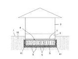
【課題】中小規模の建築物等の構築物の敷地に適した安価で施工が容易な液状化対策技術であって、十分な間隙水圧緩和の効果のある液状化対策技術を提供する。【解決手段】敷地1を掘り下げて形成された凹部に設けられた樹脂ブロック層4の上側に構築物が施工された構造であり、樹脂ブロック層4は水平に並べられた複数の樹脂ブロック5で形成されている。各樹脂ブロック5は、構築物の下側に間隙水圧緩和空間Sを形成しつつ構築物を支える樹脂(発泡スチロールを除く)製の構造部材であり、内部に水が進入できるよう開口を有する。樹脂ブロック層4は、地盤の砂を遮断しつつ水を透過させる遮砂透水シートにより全体が覆われている。【選択図】図1The present invention provides a liquefaction countermeasure technique that is suitable for a site of a structure such as a small and medium-sized building and that is inexpensive and easy to construct, and that has a sufficient effect of reducing pore water pressure. SOLUTION: A structure is constructed in a structure above a resin block layer 4 provided in a recess formed by digging down a site 1, and the resin block layer 4 is formed by a plurality of resin blocks 5 arranged horizontally. Has been. Each resin block 5 is a structural member made of resin (excluding polystyrene foam) that supports the structure while forming the pore water pressure relaxation space S on the lower side of the structure, and has an opening so that water can enter inside. The resin block layer 4 is entirely covered with a sand-permeable and water-permeable sheet that allows water to pass through while blocking the ground sand. [Selection] Figure 1
Description
この出願の発明は、敷地における液状化対策構造に関するものであり、敷地に建設される各種構築物を液状化から保護する構造に関するものである。この発明において対策が講じられる各種構築物には、家屋やビル等の建築物の他、門や壁等の外構や浄化槽等の住宅付属物、擁壁や橋梁のような建造物、さらに上下水道等のライフラインが含まれる。 The invention of this application relates to a liquefaction countermeasure structure on a site, and relates to a structure for protecting various structures constructed on the site from liquefaction. Various structures for which measures are taken in the present invention include buildings such as houses and buildings, exteriors such as gates and walls, housing accessories such as septic tanks, structures such as retaining walls and bridges, and water and sewage systems. Lifelines such as are included.
日本は地震の多い国であり、大地震の教訓を背景として各種の地震対策技術の研究や開発が進められている。このうち、沿岸部を中心として深刻な被害をもたらす液状化は、復旧に多大な費用と時間がかかることから、対策が急務となっている。液状化は、埋め立て地のような砂地の地盤であって地下の浅い所に地下水が溜まっている箇所に発生し易い。地震による振動で砂地層の砂粒子の間隔がいったん拡大して水が解き放たれ、それによって砂粒子の間隙が狭まることに起因している。水の解放と砂粒子間隔の減少により大きな間隙水圧が生じ、これにより地下水が急激に上昇して液状化に至る。液状化が生じると、周知のように、地表面の隆起や凹み、これに伴う家屋の傾斜、マンホール蓋の上昇等、被害が発生する。 Japan is an earthquake-prone country, and various earthquake countermeasure technologies are being researched and developed against the background of lessons learned from major earthquakes. Of these, liquefaction that causes serious damage, especially in the coastal areas, is a matter of urgent need to be addressed because it requires a great deal of cost and time to recover. Liquefaction is likely to occur at a place where groundwater is accumulated in a shallow ground such as a landfill such as a landfill. This is due to the fact that the distance between the sand particles in the sand layer is expanded by the vibration caused by the earthquake and the water is released, thereby narrowing the gap between the sand particles. The release of water and the reduction of the sand particle spacing creates a large pore water pressure, which causes groundwater to rise rapidly and lead to liquefaction. When liquefaction occurs, as is well known, damages such as bumps and depressions on the ground surface, the inclination of the house, and the rise of the manhole cover are caused.
液状化の対策としては、造成の際に砂地層の突き固めを行ったり(サンドコンパクション)、水抜きを十分に行ったりすることが従来行われてきた。このような対策は、埋め立て地に大規模な建築物(マンション群など)を建設するような大規模な開発の際にしばしば行われ、実際、東日本大震災のような大震災においても相当の効果が確認されている。しかしながら、このような液状化対策は非常に大がかりであり多大な費用がかかる。したがって、一戸建て用の宅地造成のような小規模の開発の場合には、採用が難しい。 As countermeasures for liquefaction, it has hitherto been carried out by tamping the sand layer (sand compaction) or sufficiently draining the water during formation. Such measures are often taken during large-scale developments such as constructing large-scale buildings (such as apartment buildings) in landfills. In fact, considerable effects have been confirmed even in major earthquakes such as the Great East Japan Earthquake. Has been. However, such liquefaction countermeasures are very large and costly. Therefore, it is difficult to adopt in the case of small-scale development such as the creation of a residential land for a detached house.
一戸建ての宅地のような小規模の建築物敷地における液状化対策として現在検討されている工法は、杭工法と表層改良工法とに大別される(http://tokyo-toshiseibi-ekijoka.jp/about001.pdf)。杭工法は、液状化することのない安定した層まで深く杭を打ち、杭で基礎を支える工法である。杭工法としては、鋼管によるものの他、セメント系材料と敷地の土砂とを混合して固めるセメント系杭工法や、砕石により杭を形成する砕石系杭工法が知られている。セメント系杭工法や砕石系杭工法は、軟弱地盤の改良工法としてしばしば採用される工法であり、柱状改良杭工法と総称される。一方、表層改良工法は、基礎の下側及び周囲において地盤をセメント系の改良材で置換する工法である。改良材は、セメントと土砂とを混合した混合材が使用される場合もあり、ガラス系の薬液が注入される場合もある。 Construction methods currently under consideration as liquefaction countermeasures for small-scale building sites such as detached houses are roughly divided into pile construction methods and surface layer improvement construction methods (http://tokyo-toshiseibi-ekijoka.jp/ about001.pdf). The pile construction method is a construction method in which the pile is driven deeply into a stable layer that does not liquefy and the foundation is supported by the pile. As a pile construction method, in addition to using a steel pipe, a cement-type pile construction method in which cement-based materials and soil on the site are mixed and hardened, and a crushed stone pile construction method in which a pile is formed by crushed stone are known. The cement pile method and the crushed stone pile method are methods often adopted as an improvement method for soft ground, and are collectively referred to as a columnar improvement pile method. On the other hand, the surface layer improvement method is a method in which the ground is replaced with a cement-based improvement material on the lower side and the periphery of the foundation. As the improving material, a mixed material obtained by mixing cement and earth and sand may be used, or a glass-based chemical solution may be injected.
これら現在検討されている小規模の建築物敷地向けの液状化対策のうち、鋼管製の杭を安定層まで打ち込む鋼管杭工法は、大がかりな工事でありコスト高となる欠点がある。また、建物の不同沈下は防止できても、液状化発生時の間隙水の上昇圧力を緩和させている訳ではないので、噴砂が地上に達し、建物周辺での被害(例えば外構の崩れ)が生じる恐れがある。 Among these liquefaction countermeasures for small-scale building sites currently under consideration, the steel pipe pile method, in which steel pipe piles are driven to the stable layer, is a large-scale construction and has the disadvantage of high costs. In addition, even if the settlement of the building can be prevented, it does not relieve the rising pressure of the pore water when liquefaction occurs, so the sand blows to the ground and damages around the building (for example, collapse of the exterior) May occur.
柱状改良杭工法は、比較的安価に施工し得る工法であり、液状化対策にもなり得るとされている。即ち、砕石系杭工法では、杭内部(砕石間の空間)を通って地下水が上昇するため、間隙水圧が緩和するとされている。また、セメント系杭工法では、杭の周面に沿って水が上昇するため、間隙水圧が緩和するとされている。しかしながら、砕石系杭工法における杭内の通水空間は微小なものであり(大きくすると杭自体の強度が低下する)、それほど大きな間隙水圧緩和の効果は得られない。また、セメント系杭工法では杭の周面に沿って上昇するのみであるので、さらに上昇量は少なく、間隙水圧緩和の効果は限定的である。そして、いずれの杭工法でも、地中水位が高い場合などには杭内には間隙水を溜める効果は実質的になく、過剰な量の間隙水が上昇してきた場合、地表面に達して噴砂となってしまうことがあり得る。また、地表面(砂地層の表面)が落ち込むことで、杭に支えられた基礎や建物が地表面から取り残される「浮き上がり現象」となる被害もあり得る。 The columnar improved pile construction method is a construction method that can be constructed at a relatively low cost and is said to be a countermeasure for liquefaction. That is, in the crushed stone pile construction method, the groundwater rises through the inside of the pile (space between crushed stones), so that the pore water pressure is alleviated. In the cement-based pile construction method, water rises along the peripheral surface of the pile, so that the pore water pressure is alleviated. However, the water flow space in the pile in the crushed stone pile construction method is very small (strengthening the strength of the pile itself when it is increased), and so much pore water pressure relaxation effect cannot be obtained. In addition, since the cement pile method only rises along the circumferential surface of the pile, the amount of rise is further small, and the effect of pore water pressure relaxation is limited. In any of the pile construction methods, there is virtually no effect of accumulating pore water in the pile when the ground water level is high, etc., and when excessive amount of pore water rises, it reaches the ground surface and blows sand. It can happen. In addition, when the ground surface (the surface of the sandy layer) falls, there may be damage that becomes a “lifting phenomenon” in which foundations and buildings supported by piles are left behind from the ground surface.
また、表層に固い層(改良層)を作って液状化対策とする表層改良の場合、間隙水圧を緩和していることにはならないので、根本的な解決にならない場合が多い。即ち、改良層により間隙水圧が分散したとしても、その周囲で噴砂が勢いよく生じ、被害が発生してしまうことがあり得る。また、改良層の下側では大きな間隙水圧が生じており、この影響で改良層の下側の地盤が不均等に緩んでしまい、不同沈下が生じることもあり得る。このため、万全な対策とはいえない。 In addition, in the case of surface layer improvement in which a hard layer (improved layer) is formed on the surface layer to prevent liquefaction, the pore water pressure is not alleviated, and thus there is often no fundamental solution. In other words, even if the pore water pressure is dispersed by the improved layer, it is possible that the sand blast will generate vigorously around it and cause damage. In addition, a large pore water pressure is generated below the improved layer, and due to this influence, the ground below the improved layer may loosen unevenly and uneven settlement may occur. For this reason, it cannot be said that it is a perfect measure.
この出願の発明は、このような課題を解決するために為されたものであり、中小規模の建築物等の構築物の敷地に適した安価で施工が容易な液状化対策技術であって、十分な間隙水圧緩和の効果のある液状化対策技術を提供することを目的としている。 The invention of this application was made in order to solve such a problem, and is a liquefaction countermeasure technique that is suitable for a site of a structure such as a small-scale building and that is inexpensive and easy to construct. The purpose is to provide liquefaction countermeasure technology that has the effect of reducing pore water pressure.
上記課題を解決するため、本願の請求項1記載の発明は、敷地において施工される液状化対策構造であって、
敷地を掘り下げて形成された凹部に樹脂ブロック層が設けられ、樹脂ブロック層の上側に構築物が設けられた構造であり、
樹脂ブロック層は、水平に並べられた複数の樹脂ブロックで形成されており、
各樹脂ブロックは、構築物の下側に間隙水圧緩和用の空間を形成しつつ構築物を支える樹脂(発泡スチロールを除く)製の構造部材であり、内部に水が進入できるよう開口を有する形状であり、
樹脂ブロック層は全体に遮砂透水シートで覆われており、遮砂透水シートは、地盤の砂を遮断しつつ水を透過させるシートであり、
遮砂透水シートは樹脂製の不織布で形成されており、不織布の見かけ開孔径O 95 は0.37mm以下であり、
樹脂ブロック層の高さをh、樹脂ブロック層の容積率をα(0<α<1)とし、敷地の地下に存在する地下水層の厚さをTとしたとき、h≧0.01T/(1−α)となっているという構成を有する。
また、上記課題を解決するため、請求項2記載の発明は、前記請求項1の構成において、前記敷地の地盤には、鉛直方向に延びる複数の支持杭が設けられており、各支持杭は、多孔構造のものであって、地震発生時に間隙水圧により地下水が内部を通って又は周面に沿って上昇するものであり、
前記樹脂ブロック層は、支持杭の内部を通って又は周面に沿って上昇する地下水が流入するよう支持杭に対して遮水層を介在させない状態で接近して設けられているか又は支持杭に接触して設けられているという構成を有する。
In order to solve the above problems, the invention according to
A resin block layer is provided in a recess formed by digging down the site, and a structure is provided on the upper side of the resin block layer.
The resin block layer is formed of a plurality of resin blocks arranged horizontally,
Each resin block is a structural member made of resin (excluding polystyrene foam) that supports the structure while forming a space for pore water pressure relaxation under the structure, and has a shape having an opening so that water can enter inside,
Resin blocking layer is covered with Saegisuna permeable sheet throughout, Saegisuna permeable sheet, Ri sheets der that transmits water while blocking sand ground,
The sand-impervious water-permeable sheet is formed of a resin nonwoven fabric, and the nonwoven fabric has an apparent opening diameter O 95 of 0.37 mm or less.
When the height of the resin block layer is h, the volume ratio of the resin block layer is α (0 <α <1), and the thickness of the underground water layer existing in the underground of the site is T, h ≧ 0.01 T / ( 1-α) .
Moreover, in order to solve the said subject, invention of
The resin block layer is provided close to the support pile without interposing a water-impervious layer so that groundwater rising through the inside of the support pile or along the peripheral surface flows into the support pile or the support pile. It has the structure of being provided in contact .
以下に説明する通り、本願の請求項1記載の発明によれば、大きな地震が発生した際、砂地質である敷地の地盤が振動によりいったん拡大した後に圧縮されて間隙水圧が発生したとしても、間隙水圧によって上昇する地下水は、遮砂透水シートを通して間隙水圧緩和空間内に浸入する。このため、液状化が地表面付近にまで達してしまい、構築物が部分的に水中に埋没して傾いてしまったり、軽い部分が水圧によって持ち上げられてしまったりといった液状化の被害が防止される。
また、遮砂透水シートは樹脂製の不織布で形成されており、不織布の見かけ開孔径O95は0.37mm以下であるので、液状化が生じ易い砂質においてより確実に被害防止の効果が得られる。
さらに、樹脂ブロック層の高さh、樹脂ブロック層の容積率α、地下水層の厚さTについて、h≧0.01T/(1−α)となっているので、地下水層の厚さに応じた間隙水圧緩和空間が確保され、この点で被害防止の効果がより確実となる。
また、請求項2記載の発明によれば、上記効果に加え、樹脂ブロック層は、柱状改良杭と通して上昇する地下水が流入する位置に設けられているので、柱状改良杭による地盤改良の効果に加え、柱状改良杭を地下水の上昇経路として利用しつつ間隙水圧を緩和させることができる。このため、液状化が地表面にまで達して被害が生じるのを防止する効果がさらに高く得られる。
As described below, according to the invention of
Further, Saegisuna permeable sheet is formed of a resin nonwoven fabric, since the apparent pore size O 95 of the nonwoven fabric are as follows 0.37 mm, obtained the effect of more reliably prevent damage in liquefaction occurs easily sandy It is done.
Furthermore, since the height h of the resin block layer, the volume ratio α of the resin block layer, and the thickness T of the groundwater layer are h ≧ 0.01T / (1-α), depending on the thickness of the groundwater layer The pore water pressure relief space is secured, and the effect of preventing damage is more certain in this respect.
Moreover, according to invention of
次に、本願発明を実施するための形態(以下、実施形態)について説明する。
図1は、実施形態の液状化対策構造を有する構築物の概略図である。図1に示す構築物は、敷地1の地盤10の上に施工された基礎2と、基礎2の上に施工された建物3とから成っている。
実施形態の液状化対策構造の大きな特徴点は、基礎2の下に大きな空間(空洞)Sを形成し、液状化発生時にこの空間内に水を引き込むことで間隙水圧を緩和する点である。以下、この空間Sを間隙水圧緩和空間と呼ぶ。
Next, modes for carrying out the present invention (hereinafter referred to as embodiments) will be described.
Drawing 1 is a schematic diagram of a structure which has a liquefaction measures structure of an embodiment. The structure shown in FIG. 1 includes a
A major feature of the liquefaction countermeasure structure of the embodiment is that a large space (cavity) S is formed under the
間隙水圧緩和空間Sは、多数の樹脂ブロック5によって形成されている。多数の樹脂ブロックは、水平方向に並べられて配置されており、水平方向に延びる層(樹脂ブロック層)4を形成している。各樹脂ブロック5は、間隙水圧緩和空間Sを形成するものではあるものの、基礎2及び建物3を支える構造部材であるため、十分な強度を有するものとなっている。
The pore water pressure relaxation space S is formed by a large number of resin blocks 5. A large number of resin blocks are arranged in the horizontal direction, and form a layer (resin block layer) 4 extending in the horizontal direction. Although each
図2は、図1に示す樹脂ブロック層4を構成する樹脂ブロック5の概略図であり、(1)が平面概略図、(2)は正面概略図である。樹脂ブロック5は、水平な姿勢とされるベース部51と、ベース部51から垂直に延びるよう形成された脚部52とから成っている。ベース部51は、全体としては正方形の板状である。ベース部51には、多くの開口50が形成されている。
脚部52は、正方形のベース部51の各角の位置に合計4つ設けられている。脚部52の位置は、角の縁から少し内側の位置である。各脚部52は、対角線上に位置し、角の縁からの距離はすべて同じである。
FIG. 2 is a schematic view of a
A total of four
各脚部52は、全体としてはほぼ角柱状の部位である。但し、各脚部52の内部は空洞になっている。各脚部52は、ベース部51につながった部分で最も断面積が大きく、ベース部51から遠ざかるにしたがって徐々に小さな断面積となっている。即ち、正面から見ると台形状となっている。
各脚部52の高さは皆同じである。各脚部52の上端面には、嵌め込み用の突起(以下、嵌め込み突起)53が形成されている。嵌め込み突起53は、上側に位置させる別の樹脂ブロック5との組み合わせのための部位である。
Each
The height of each
図2(1)に示すように、嵌め込み突起53は、各脚部52の上端面に二つずつ形成されている。各嵌め込み突起53は、図2(1)に示すように、各脚部52のほぼ正方形の上端面形状において斜め左上から斜め右下の方向の対角線上に設けられている。
また、各脚部52の上端面には、嵌め込み用の孔(以下、嵌め込み孔)54が形成されている。嵌め込み孔54は、嵌め込み突起53が嵌め込まれる孔である。嵌め込み孔54も、各上端面に二つずつ設けられている。嵌め込み孔54は、平面視で見た場合、斜め右上から斜め左下の方向の対角線上に設けられている。即ち、各脚部52の上端面において、各嵌め込み孔54は各嵌め込み突起53と線対称に配置されている。
As shown in FIG. 2A, two
A fitting hole (hereinafter referred to as a fitting hole) 54 is formed on the upper end surface of each
間隙水圧緩和空間Sを形成するというだけであれば、樹脂ブロックではなく例えばスチール製の構造材を使用することも可能である。しかしながら、スチール製の鋼材を組み立てることで間隙水圧緩和空間Sを形成することは、材料コストが高くなり、また施工も面倒となる。また、間隙水圧緩和空間Sは、内部に水が進入することを想定しており、水は長期間滞留することがあるので、腐食性の材料は使用できない。実施形態の構造では、このような点を考慮し、樹脂ブロックを並べることで間隙水圧緩和空間Sを形成している。 If only the pore water pressure relaxation space S is formed, it is also possible to use, for example, a steel structural material instead of the resin block. However, forming the pore water pressure relaxation space S by assembling a steel material made of steel increases the material cost and makes the construction troublesome. Further, the pore water pressure relaxation space S assumes that water enters the inside, and water may stay for a long period of time, so that a corrosive material cannot be used. In the structure of the embodiment, in consideration of such points, the pore water pressure relaxation space S is formed by arranging resin blocks.
樹脂ブロックの必要な強度について説明すると、特に鉛直方向の長期許容応力度(クリープ)の大きさが問題となる。この値は、一戸建ての住宅や三階建て程度までの建設物を想定すると、30kN/m2以上とすることが望しく、50kN/m2以上とすることがより望ましい。さらに、高層のビルやマンションのような大規模の建築物を想定すると、100kN/m2以上とすることが望ましい。樹脂ブロックの材料は、この実施形態では、ポリプロピレンと高密度ポリエチレンの混合材が使用されている。混合比は、重量比でポリプロピレン30〜50%(ポリエチレン70〜50%)程度である。この実施形態では、環境面及びコスト面を考慮し、PP、PEとも再生材(リサイクルされた材料)を使用している。 The required strength of the resin block will be described. Particularly, the magnitude of the long-term allowable stress (creep) in the vertical direction becomes a problem. This value, assuming construction of up houses and about stories of detached, it is Nozomu properly, it is more desirable that the 50 kN / m 2 or more to 30 kN / m 2 or more. Furthermore, assuming a large-scale building such as a high-rise building or condominium, it is desirable to set it to 100 kN / m 2 or more. In this embodiment, the material of the resin block is a mixed material of polypropylene and high density polyethylene. The mixing ratio is about 30 to 50% polypropylene (70 to 50% polyethylene) by weight. In this embodiment, considering the environmental aspect and the cost aspect, recycled materials (recycled materials) are used for both PP and PE.
より具体的な一例を示すと、樹脂ブロック5としては、例えば株式会社日東ジオテクノ(本社、東京渋谷)からジオプールの商品名で販売されているもの(例えばAE−1)が使用できる。この種の樹脂ブロック5は、人が一人で持ち運びできる程度の軽量なものとなっており、ベース部51は一辺が500〜750mm程度であり、脚部52の長さ(高さ)は250〜400mm程度、重量は3〜6kg程度である。
As a more specific example, as the
後述するように、間隙水圧緩和空間Sは、地震発生時に上昇する間隙水を取り込んで間隙水圧を緩和するものであるから、ある程度の大きさの空間が必要である。このため、図1に示すように、樹脂ブロック5は、水平方向及び垂直方向に隙間無く並べて敷設される。この際、上下方向では、各嵌め込み突起53を各嵌め込み孔54に嵌め込むことで組み上げを行う。即ち、図1に示すように、下側の樹脂ブロック5は、脚部52を上に向けて配置される。そして、その上に脚部52を下に向けて別の樹脂ブロック5を配置する。この際、お互いの脚部52を突き合わせ、互いの嵌め込み突起53が互いの嵌め込み孔54に嵌め込まれるようにする。このような樹脂ブロック5を脚部52を突き合わせて重ね合わせ、例えば150kN/m2までの荷重に耐えられるようにする。
また、図1に示すように、最も外側に位置する上下一対の樹脂ブロック5の外側には、壁材プレート41が設けられている。壁材プレート41の詳細構造の図示は省略するが、壁材は、同様に樹脂製の板状部材であり、通水用の開口を多数有している。凹凸が嵌り合う構造により、壁材プレート41は各樹脂ブロック5に連結されている。尚、壁材プレート41は、より強度を高めるため、上下各対の樹脂ブロック5の各側部に設けられる場合もある。
As will be described later, the pore water pressure relaxation space S takes in pore water that rises when an earthquake occurs and relaxes the pore water pressure, and therefore requires a certain amount of space. For this reason, as shown in FIG. 1, the resin blocks 5 are laid side by side in the horizontal direction and the vertical direction without any gaps. At this time, in the vertical direction, assembly is performed by fitting each
Moreover, as shown in FIG. 1, the
尚、脚部52を下側に向けて配置された樹脂ブロック5の上には、脚部52を上に向けた別の樹脂ブロック5が積み重ねられる場合があるが、この場合には、ベース部51に嵌め込み用の突起及び孔が設けられたタイプの樹脂ブロックが使用される。上側に設けられる樹脂ブロックのベース部にも、対応する位置に孔と突起が設けられており、ベース部を向かいあせて接合しながらお互いの突起がお互いの孔に嵌り込むことで連結される。上下に並ぶ樹脂ブロックが水平方向でずれるのが防止される。
In addition, another
このように多数の樹脂ブロックを並べて形成した樹脂ブロック層4は、全体が遮砂透水シート6で覆われている。「遮砂透水シート」という用語は一般的ではないが、地盤10の砂は遮断して通さないものの水は通すシートという意味である。
上記のように各樹脂ブロック5は、開口50を多数有する形状であり、内部に水が浸入し得る。液状化発生時には、高い間隙水圧によって上昇する水は、開口50を通して各樹脂ブロック5内に浸入するが、単に樹脂ブロック5を並べただけであると、周囲の砂(敷地の地盤10の砂)を巻き込んで浸入してしまう。こうなると、地盤10が削り取られたような状態になり、不同沈下を誘発してしまうことがあり得る。
The
As described above, each
実施形態では、この問題を考慮し、遮砂透水シート6で樹脂ブロック層4を覆っている。一般に、砂とは、粒径が0.075mm〜2mmの粒子のものを言うので、遮砂透水シート6としては、開孔の大きさが0.075mm以下であれば理論的に遮砂透水が可能である。しかしながら、そのように細かい開孔でなくとも実際には砂の遮断は可能であるし、また液状化が生じ易い砂の粒径がある範囲に入ることが既に報告されている。
In the embodiment, in consideration of this problem, the
例えば、平成23年度日本大学理工学部学術論文集B75に掲載されている「2011年東北地方太平洋沖地震による液状化被害調査 噴砂と粒度特性と液状化被害状況」には、東京湾沿岸部と利根川下流沿岸の液状化発生地点での噴砂の粒度測定の結果が報告されている。この報告によると、液状化発生地点の砂の平均粒径は0.093〜0.317mmで、均等係数Ucは2.2〜6.9となっている。また、土木学会が発表した「2007年能登半島地震被害調査報告書」の「第3章 液状化」の109頁には、噴砂の粒径加積曲線が示されており、概ね0.1〜1mmの粒径の砂地質において液状化が生じ易いとして良い。従って、0.1mm程度以上の粒径の砂を遮断できるものであれば、遮砂透水シート6として使用できると推測できる。
For example, the “Liquefaction damage survey due to the 2011 Tohoku-Pacific Ocean Earthquake, sand granulation characteristics, and liquefaction damage status” published in Academic Papers B75 of Nihon University College of Science and Technology in 2011 includes the coastal areas of Tokyo Bay and Tonegawa The result of particle size measurement of sand sand at the liquefaction occurrence point on the downstream coast has been reported. According to this report, the average particle size of sand at the liquefaction occurrence point is 0.093 to 0.317 mm, and the uniformity coefficient Uc is 2.2 to 6.9. Page 109 of “
一方、ジオシセティックス論文集第21巻(2006年12月)の327〜332頁に掲載されている「種々と土質を用いた透水試験によるジオテキスタイルフィルターの目詰まり特性」では、GTX−S14、GTX−S40、GTX−D80という三つのジオテキスタイルの目詰まり特性の評価結果が報告されている。このうち、平均粒径0.17mmの六戸細粒分質砂では、それぞれのジオテキスタイルについて、5×10⁻⁴cm/秒を超える透水係数が経時的に得られている(330頁の図9)。この論文では、それぞれの開孔径に応じた目詰まりが報告されているものの、液状化発生時には高い間隙水厚を受けることを考慮すれば、5×10−4cm/秒以上の透水係数は十分な値である。逆に目詰まりがないとすると、かなりの量の砂が通過していると推測され、問題となり得る。 On the other hand, “Clogging characteristics of geotextile filter by water permeability test using various soils” published on pages 327 to 332 of Geocitics Papers Vol. 21 (December 2006), GTX-S14, Evaluation results of clogging characteristics of three geotextiles, GTX-S40 and GTX-D80, have been reported. Among these, in the Hokunohe fine granulated sand having an average particle size of 0.17 mm, a water permeability coefficient exceeding 5 × 10 −4 cm / sec is obtained over time for each geotextile (FIG. 9 on page 330). . In this paper, although clogging according to the respective pore diameters is reported, a water permeability coefficient of 5 × 10 −4 cm / sec or more is sufficient considering that a high pore water thickness is received when liquefaction occurs. Value. On the other hand, if there is no clogging, it is assumed that a considerable amount of sand has passed, which can be a problem.
三つのジオテキスタイルのうち、見かけ開孔径が最も大きいのはGTX−S14で、その値は0.37mmである。従って、0.37mm以下の見かけ開孔径のジオテキスタイルが使用できるとして良い。ちなみに、GTX−S40のみかけ開孔径は0.190mm、GTX−D80の見かけ開孔径は0.090mmである。これらジオテキスタイルも遮砂透水シートとして勿論使用することができる。尚、ジオテキスタイルの開孔径を直接測定することは難しいため、通常、見かけ開孔径を用いる。例えば、見かけ開孔径O95は、ジオテキスタイル試験片を通過した粒状体の粒径加積曲線より,通過質量百分率の95%粒径に対応する粒径として定義される。上記各値もO95での値であり、特に乾式の開孔径試験による値である。
尚、以上は不織布の場合であるが、織布の場合も同様に見かけ開孔径O95が0.37mm以下であるものが使用できる。このような織布の遮砂透水シートとしては、例えば2mm以上の厚さのポリプロピレン製の織布を使用することができる。
Of the three geotextiles, GTX-S14 has the largest apparent pore diameter, and its value is 0.37 mm. Accordingly, a geotextile having an apparent opening diameter of 0.37 mm or less may be used. Incidentally, the apparent aperture diameter of GTX-S40 is 0.190 mm, and the apparent aperture diameter of GTX-D80 is 0.090 mm. Of course, these geotextiles can also be used as sand-permeable and water-permeable sheets. In addition, since it is difficult to directly measure the opening diameter of geotextile, the apparent opening diameter is usually used. For example, the apparent pore size O 95 is defined as a particle size corresponding to 95% particle size of the passing mass percentage from the particle size accumulation curve of the granular material that has passed through the geotextile test piece. Each of the above values is also a value at O 95 , particularly a value obtained by a dry-type hole diameter test.
The above is the case of the nonwoven fabric, those pore size O 95 apparent Similarly for fabric is less than 0.37mm may be used. For example, a woven fabric made of polypropylene having a thickness of 2 mm or more can be used as the sand-permeable and water-permeable sheet of such a woven fabric.
次に、このような液状化対策構造の施工方法について、図3を使用して説明する。図3は、実施形態の免震構造を有する建築物の施工方法を示した概略図である。
まず、図3(1)に示すように、敷地1の地盤10を掘り下げ、底面を平らにする。そして、掘り下げて形成した凹部の底面及び側面を覆うようにして遮砂透水シート61を被せる。その後、底面に砕石72を敷き詰める。
Next, the construction method of such a liquefaction countermeasure structure is demonstrated using FIG. Drawing 3 is a schematic diagram showing the construction method of the building which has the seismic isolation structure of an embodiment.
First, as shown in FIG. 3 (1), the
次に、図3(2)に示すように、砕石72の上に別の遮砂透水シート6を敷き、その上に樹脂ブロック5を並べていく。そして、並べた各樹脂ブロック5の上側に別の樹脂ブロック5を向かい合わせて(脚部52を互いに突き合わせるようにして)配置し、上下二段の樹脂ブロック層4を形成する。その上で、樹脂ブロック層4全体を遮砂透水シート6で覆う。遮砂透水シート6の端は、必要に応じて粘着テープ等で貼り合わせる。
次に、図3(3)に示すように、樹脂ブロック5の上に緩衝層7を施工する。即ち、リプラボード又はEPSボードを並べて載置し、樹脂ブロック層4の上側を覆った状態で敷き詰めて緩衝層7とする。また、敷地1を掘り下げて形成した凹部と樹脂ブロック層4の側面との間には、若干の空間が残るが、この空間には、砕石72が充填される。
Next, as shown in FIG. 3 (2), another sand-blocking water-
Next, as shown in FIG. 3 (3), a
そして、図3(4)に示すように、緩衝層7の上に基礎2を施工し、基礎2の上に建物3を施工する。基礎2や建物3の施工法は、特に制限されるものではなく、適宜の工法を用いることができる。尚、基礎2を施工した後、樹脂ブロック層4の上側に空間では、基礎2の周囲を含めて埋め戻しがされ、適宜の高さの地表面とされる。このため、基礎2の一部や樹脂ブロック層4は、地中に埋設された状態となる。
Then, as shown in FIG. 3 (4), the
次に、実施形態の液状化対策構造の作用について説明する。図4は、実施形態の液状化対策構造の作用について示した正面断面概略図である。
実施形態の構造において、図4(1)に示すように、敷地1の地盤10は砂地層11となっており、且つ敷地1の地下の比較的浅い位置に地下水層12が存在している。この状態において、大きな地震が発生し、地震の振動により砂地層11,12がいったん緩んで大きな間隙水圧が地下水層12に生じたとする。この結果、図4(2)に示すように、地下水Wが急激に上昇し、液状化の発生となる。
Next, the effect | action of the liquefaction countermeasure structure of embodiment is demonstrated. FIG. 4 is a schematic front cross-sectional view illustrating the action of the liquefaction countermeasure structure of the embodiment.
In the structure of the embodiment, as shown in FIG. 4 (1), the
この際、図4(2)に示すように、上昇する地下水Wは、その多くが遮砂透水シート6,61を通って樹脂ブロック層4内の間隙水圧緩和空間Sに浸入する。このため、間隙水圧は、樹脂ブロック層4の部分で大幅に緩和される。この結果、地下水Wが地表面にまで達して噴砂となったり、地表面が液状化して基礎2や建物3が傾いてしまったりするのが防止される。
尚、樹脂ブロック層4の下側での砂地層11の液状化により、樹脂ブロック層4が全体に沈下し得る。但し、樹脂ブロック層4により上載圧は軽量化され且つ均等になっているので、沈下は小さく、また均等(同沈下)である。
At this time, as shown in FIG. 4B, most of the rising groundwater W enters the pore water pressure relaxation space S in the
In addition, the
発明者は、このような液状化対策構造について、実際に実験を行ってその効果を確認している。以下、この点について説明する。図5は、実施形態の液状化対策構造の効果を確認するために行った実験について示した正面断面概略図である。この実験では、プロトタイプとして図5に示すような構造を製作し、実際に振動台の上に載せて振動させ、振動実験を行った。図5(1)が従来構造のプロトタイプを示し、図5(2)が実施形態の構造のプロトタイプを示す。 The inventor has actually conducted an experiment on such a liquefaction countermeasure structure and confirmed its effect. Hereinafter, this point will be described. FIG. 5 is a schematic front sectional view showing an experiment conducted for confirming the effect of the liquefaction countermeasure structure of the embodiment. In this experiment, a structure as shown in FIG. 5 was manufactured as a prototype, and it was actually placed on a vibration table and vibrated to conduct a vibration experiment. FIG. 5 (1) shows a prototype of the conventional structure, and FIG. 5 (2) shows a prototype of the structure of the embodiment.
この実験では、木材で2.5m×2.5m、高さ1.2m程度の直方体状の仮想地盤容器91を製作し、仮想地盤容器91を振動台92の上に固定した。そして、容器の内側面に発砲樹脂プレートを側面緩衝材93として設け、側面緩衝材93で取り囲まれた状態で構造プロトタイプ配置した。
構造プロトタイプとしては、まず、仮想地盤容器91の底面及び側面緩衝材93の内側面を覆うようにして防水シート931を敷設した。そして、底面の防水シート931の上に厚さ150mmのウレタン樹脂層94を設け、その上に砂を投入して厚さ300mm程度の細砂層95を形成した。ウレタン樹脂層94+細砂層95が、砂地層11を有する地盤10をシミュレートした層である。
In this experiment, a
As a structural prototype, first, a
そして、基礎2+建物3の荷重に相当するものとして、厚さ150mmのプレキャストコンクリートブロック(以下、PC)を並べPC層96を配置した。PC層96の外形は1500mm角であるが、中央に内部の状況を確認するための点検口(直径900mm)を設けた。PC層96の荷重は700kgである。また、全体のバランスを構築物3に近づけるため、PC層96の上に角筒体98(高さ1m程度)を取り付けた。
尚、実際の施工では基礎2の一部は地中に埋設された状態となるため、PC層96の下面は砕石層95の上面より少し下側になるように、砕石層95の上面に凹部を形成し、その中にPC層96が入り込んだ状態とした。
And as what corresponds to the load of
In actual construction, since a part of the
図5(1)に示すように、従来構造のプロトタイプでは、PC層96の周囲に砕石層99を設け、基礎2の一部が地中に埋設されている構造をシミュレートした。また、実施形態の構造のプロトタイプでは、細砂層95の上に遮砂透水シート6を敷いた上で厚さ300mmの樹脂ブロック層4を設け、遮砂透水シート6で樹脂ブロック層4全体を覆った。その上に緩衝層7として厚さ3mmのリプラボードを設けた。樹脂ブロック層4は、図1に示す実施形態とは異なり、樹脂ブロック5を一段のみ並べた構造のものである。また、樹脂ブロック層4の周囲にも砂を投入して細砂層95とし、その上に若干の砕石層99を設けた。尚、使用した遮砂透水シート6は、前述したGTX−S40(見かけ開孔径0.19mm)である。
そして、従来構造及び実施形態の構造とも、防水シート931内に水Wを投入して水を溜め、貯水槽100を形成して地下水層のシミュレーションとした。貯水槽100は、仮想地盤容器91の底面から300mmの高さに達するまで投入した。この水量は、従来構造及び実施形態の構造とで同じである。
As shown in FIG. 5A, in the prototype of the conventional structure, a crushed
In both the conventional structure and the structure of the embodiment, water W is poured into the
このような状態とした上で、振動台92を動作させて振動を各構造プロトタイプに印加し、振動波形や水Wの状態を観察した。尚、図示は省略したが、PC層96の下端部に振動センサが設けられた。振動センサとしては、地震計と同様、加速度センサが使用された。また、印加した振動については、実際の地震のシミュレーションとするため、K−NET日立(IBR003)を採用した。
In such a state, the vibration table 92 was operated to apply vibration to each structure prototype, and the vibration waveform and the state of the water W were observed. Although not shown, a vibration sensor is provided at the lower end of the
振動印加後、構造プロトタイプの状態を確認すると、従来構造では、PC層96が水で濡れており、振動印加時に水が上昇してPC層96にまで達したことが確認された(液状化発生)。また、PC層96及び角筒体98に傾斜が生じているのが確認され、液状化の被害がシミュレートされた。
一方、実施形態の構造では、PC層96は濡れておらず、PC層96や角筒体98の傾斜は目視では確認できなかった。PC層96や角筒体98を取り外し、リプラボード(緩衝層7)や上側の樹脂ブロック5も取り外して内部を確認すると、樹脂ブロック層4内に多くの水が浸入しているのが確認された。図6は、この様子を写した写真である。
When the state of the structure prototype was confirmed after applying the vibration, it was confirmed that in the conventional structure, the
On the other hand, in the structure of the embodiment, the
また、図7は、実験において振動センサで計測された振動波形を示す図である。図7(1)は、従来構造のプロトタイプにおける振動波形、図7(2)は実施形態の構造のプロトタイプにおける振動波形を示す。両者を比較すると判るように、実施形態の構造では、振動自体が大きく緩和されている。これは、樹脂ブロック層4を形成する各樹脂ブロックが適度な弾性を有するため、樹脂ブロック層4全体が免震ゴムのような働きをし、振動を緩和させているものと考えられる。即ち、実施形態の液状化対策構造では、液状化被害の防止とともに建物3の振動抑制(免震)の効果も得られる。
FIG. 7 is a diagram showing a vibration waveform measured by the vibration sensor in the experiment. FIG. 7A shows the vibration waveform in the prototype of the conventional structure, and FIG. 7B shows the vibration waveform in the prototype of the structure of the embodiment. As can be seen by comparing the two, the vibration itself is greatly reduced in the structure of the embodiment. It is considered that this is because each resin block forming the
この実験で確認されたように、実施形態の液状化対策構造によれば、大きな地震が発生した際、振動によって砂地質の地盤10がいったん緩んだ後に圧縮されて間隙水圧が発生したとしても、間隙水圧によって上昇する地下水は、遮砂透水シート6を通して間隙水圧緩和空間S内に浸入する。このため、液状化が地表面付近にまで達してしまい、基礎2や建物3が部分的に水中に埋没して傾いてしまったり、地表面の軽い部分が水圧によって持ち上げられてしまったりといった液状化の被害が防止される。
As confirmed in this experiment, according to the liquefaction countermeasure structure of the embodiment, even when a large earthquake occurs, even if the
尚、間隙水圧緩和空間Sの容積は、敷地地下の水量や地下水が存在する位置(深さ)により適宜決められる。以下、この点について図8を使用して説明する。図8は、間隙水圧緩和空間Sの容量について示した正面断面概略図である。
図8において、基礎2の占有領域をAとする。ベタ基礎の場合、占有領域Aは建物3の底面の領域と実質的に同じになる。布基礎の場合には、外郭(外側の輪郭)が取り囲む領域が占有領域Aとなり、これも建物3の底面の領域と実質的に同じである。
In addition, the volume of the pore water pressure relaxation space S is appropriately determined depending on the amount of water underground and the position (depth) where the groundwater exists. Hereinafter, this point will be described with reference to FIG. FIG. 8 is a schematic front sectional view showing the capacity of the pore water pressure relaxation space S. FIG.
In FIG. 8, the occupied area of the
間隙水圧緩和空間Sは、液状化が敷地1の地表面にまで達しないように間隙水圧を緩和するものであるから、間隙水圧緩和空間Sを提供する樹脂ブロック層4の水平方向の領域(この領域の面積をRとする)は、基礎2の占有領域Aと同じとされ、樹脂ブロック層4の位置は、基礎2の直下の位置とされる。即ち、基礎2の占有領域Aの面積はRに等しい。
また、樹脂ブロック層4の高さhは、間隙水圧緩和空間Sの容積Qを決めるものであり、R×hが十分な間隙水圧緩和作用をもたらすよう決められる。図8において、地下水層12の厚さをTとし、地下水層12までの深さをDとする。地下水層12の厚さTは、その下の安定層13から砂地層11までの高さである。また、樹脂ブロック層4の全体の容積に対して各樹脂ブロック5の肉厚部が占める空間の容積を容積率と呼び、α(0<α<1)で表す。即ち、樹脂ブロック層5の全体の容積をQ’とすると、間隙水圧緩和空間Sの容積Q=(1−α)Q’である。
Since the pore water pressure relaxation space S is for relaxing the pore water pressure so that liquefaction does not reach the ground surface of the
The height h of the
地下水層12は、実際は、砂地層に地下水が浸透している状態である。通常、砂地層における地下水の最大含有量は、体積の20%と言われている。従って、図8において基礎2の直下の位置での地下水の予想される最大量は、R×T×0.2となる。また、液状化の際に地下水のすべてが上昇するのではなく、上昇して地表面付近に達するのはその一部である。その割合をkとすると、kの値は、地下水層12までの深さDにより多少異なるが、実際には1〜2%程度である。従って、安全率を考慮して5%程度とすることができ、予想される地下水Wの最大上昇量はkを0.05として計算して良い。
The
つまり、予想される間隙水の上昇量は、0.2kRTとなり、間隙水圧緩和空間Sの容積Qは、この量以上としておけば良いから、樹脂ブロック層4の容積Q’は、Q’=Q/(1−α)≧0.2kRT、即ち、Q’≧0.2kRT/(1−α)ということになる。従って、樹脂ブロック層5の高さhは、h=Q’/Rであるので、k=0.05とすると、h≧0.01T/(1−α)ということになり、0.01T/(1−α)以上の高さで樹脂ブロック層4を形成しておけば、深さDが最も浅いケースでも地下水が地表面に達するのが確実に防止できることになる。例えば、地下水層12の厚さTが10m、樹脂ブロック5の容積率が20%であれば、h≧0.125mということになる。尚、深さDが深い場合には、kの値はより小さく評価して良いから、上記よりも低い高さhとされることもあり得る。
That is, the expected increase amount of the pore water is 0.2 kRT, and the volume Q of the pore water pressure relaxation space S may be set to be equal to or larger than this amount. Therefore, the volume Q ′ of the
上記の想定は、間隙水圧緩和空間Sの水平方向の領域(即ち、樹脂ブロック層4の水平方向の領域)が基礎2の占有領域Aと同じであることを前提にしている。液状化対策効果をより高くするには、基礎2の直下の領域を含めその領域より広い領域を間隙水圧緩和空間Sの領域とすることがより好ましい。この場合には、間隙水圧緩和空間Sの容積も大きくなるから、その分、高さhを小さくしてもよく、そのように設計されることもあり得る。また逆に、地下水量(0.2RT)に応じてhを十分に高くしておけば、基礎2の占有領域Aに比べて間隙水圧緩和空間Sの領域Rを小さくすることも可能である。
尚、上記想定において、地中水層12までの深さDは、季節に応じて変化し得る(例えば雨季には浅くなる)。従って、ボーリング調査の際の時期を考慮し、一年の平均的な値を過去のデータから推算して求めるようにする。
The above assumption is based on the assumption that the horizontal region of the pore water pressure relaxation space S (that is, the horizontal region of the resin block layer 4) is the same as the occupied region A of the
In the above assumption, the depth D to the
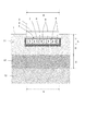
次に、第二の実施形態の液状化対策構造について説明する。図9及び図10は、第二の実施形態の液状化対策構造を示した図であり、図9は正面断面概略図、図10は平面概略図である。
第二の実施形態の構造は、前述した杭工法に本願発明の技術思想を適用したものであり、杭工法の欠点を解消したものとなっている。即ち、図9及び図10に示すように、第二の実施形態では、敷地1の地盤10に柱状改良杭8が設けられている。
Next, the liquefaction countermeasure structure of the second embodiment will be described. 9 and 10 are views showing the liquefaction countermeasure structure of the second embodiment, FIG. 9 is a schematic front sectional view, and FIG. 10 is a schematic plan view.
The structure of the second embodiment is obtained by applying the technical idea of the present invention to the above-described pile construction method, and eliminates the drawbacks of the pile construction method. That is, as shown in FIGS. 9 and 10, in the second embodiment, the columnar
柱状改良杭8は、通常、軟弱地盤における地盤改良のために設けられる。柱状改良杭8は、図10に示すように、間隔をおいて複数設けられる。柱状改良杭8の本数や間隔は、地盤10の固さ(軟弱度)や建築物全体の荷重に応じて適宜決められる。
各柱状改良杭8は、軟弱層を貫通し、安定層13に達する長さ(深さ)とされる。軟弱層は、この例では、地下水層とその上の砂地層11を含む層である。各柱状改良杭8については、液状化対策も兼ねるため、砕石系杭工法が採用されている。この実施形態では、細長く掘り下げた空間内に砕石を詰め込むことで各柱状改良杭8が形成されている。このため、各柱状改良杭8はポーラスな(多孔構造)となっており、水が通過できるようになっている。
The columnar
Each columnar
そして、図9に示すように、柱状改良杭8に加えて、基礎2の下側には樹脂ブロック層4が設けられている。樹脂ブロック層4は、図10に示すように、全体の形状が格子状となっておいる。各柱状改良杭8は、樹脂ブロック層4の格子の間及び格子の外側に設けられており、平面視では樹脂ブロック5とは重ならない位置となっている。
但し、各樹脂ブロック5と各柱状改良杭8とは接近しており、両者の距離は短くなっている。各樹脂ブロックの周囲に設けられた砕石と各柱状改良杭8とが接触している場合もある。
And in addition to the
However, each
また、第二の実施形態では、図9に示すように、各柱状改良杭8の上端と基礎2との間にも樹脂ブロック層(以下、別の樹脂ブロック層)400が設けられている。別の樹脂ブロック層400(図10では不図示)は、間隙水圧緩和空間Sの全体の容積をさらに大きくする目的の他、免震の目的でも設けられている。各柱状改良杭8は、大きな地震が発生した際、基礎2や建物3に対して振動を伝える経路になり易いという欠点がある。これを考慮し、この実施形態では、別の樹脂ブロック層400を介在させている。
Moreover, in 2nd embodiment, as shown in FIG. 9, the resin block layer (henceforth another resin block layer) 400 is provided also between the upper end of each
樹脂ブロック層400は、樹脂ブロック5で形成された層であるため、柱状改良杭8や基礎2に対して固有振動数の相違が大きい。また、地震発生時には、地盤10と基礎2や建物3との間で振動の動的相互作用が生じるが、樹脂ブロック層が存在していると、動的相互作用における位相差を大きくし、進行波と反射波とが互いに弱め合うように作用する。このようなことから、介在させた別の樹脂ブロック層400が免震の役目を果たす。
Since the
別の樹脂ブロック層400は、全体として平板状の樹脂ブロックによって形成されたものとなっている。平板状の樹脂ブロックの例について、図11を使用して説明する。図11は、図9の別の樹脂ブロック層400を形成する平板状の樹脂ブロックの概略図であり、(1)は平面概略図、(2)は正面概略図である。
この例の樹脂ブロック5は、ほぼ方形の平板状のものとなっている。樹脂ブロック5は、概略的には皿状に凹んだ凹部内に格子状に補強用のリブ55を形成した構造となっている。また、図2に示す樹脂ブロック5と同様、通水用の開口50を多数有している。
Another
The
この例の樹脂ブロック5は、一対のものを上下に重ね合わせて使用することが想定されている。上下に重ね合わせた際、水平方向で位置ずれがないようにするための嵌め込み突起56と嵌め込み孔57を同様に有している。即ち、一対の樹脂ブロックが向かい合わされて重ねられた際、各嵌め込み突起56が相手方の各嵌め込み孔57に嵌り込むよう、各嵌め込み突起56及び各嵌め込み孔57の位置が設定されている。
It is assumed that the
尚、この例の樹脂ブロック5は、前述したカバー材6としても兼用できるものとなっている。即ち、脚部52を有するタイプの樹脂ブロック5の嵌め込み突起53が嵌り込むものとして、補助嵌め込み孔58を有している。補助嵌め込み孔58に対しては、脚部52が接続された際の補強用として円弧状の補助リブ59が形成されている。
The
図11に示すような平板状の樹脂ブロック5は、図9に示すような厚さが比較的薄い樹脂ブロック層400を形成する場合に好適に使用される。形成する樹脂ブロック層400の厚さに合わせて、重ね合わせる対の数が選定される。尚、図9において、形成された樹脂ブロック層400は、同様に遮砂透水シート(不図示)で覆われている。
A
また、第二の実施形態では、建物3以外の構築物についても液状化対策が施されている。即ち、図9に示すように、建物3には、上排水管のようなライフライン31が付設されている。ライフライン31は、通常、基礎311の上に施工される。この基礎の下側に、同様に樹脂ブロック層4が施工されている。さらに、建物3の周囲には塀32が施工されている。塀32も、基礎321の上に施工されている。そして、この基礎321の下側にも、樹脂ブロック層4が施工されている。
In the second embodiment, countermeasures for liquefaction are also taken for structures other than the
このような第二の実施形態の液状化対策構造の施工方法について、以下に説明する。まず、各柱状改良杭8の施工が行われる。各柱状改良杭8は、地盤10を細長く掘り下げるドリル状の専用の建設機械(以下、柱状改良機という)を使用して行われる。柱状改良機のドリルは、地盤10を掘り下げなら固化材を投入できるようになっており、地盤の土又は砂と固化材を混ぜ合わせながら柱状の固化物(柱状改良杭)を形成できるものとなっている。
The construction method of such a liquefaction countermeasure structure of the second embodiment will be described below. First, construction of each columnar
各柱状改良杭8の施工が完了した後、地盤10を格子状に掘り下げる。掘り下げる形状、位置は、図10に示す形状、位置であり、各柱状改良杭8の施工箇所には重ならないようにする。そして、掘り下げた凹部(格子状の溝)の底面及び側面を覆うようにして遮砂透水シート61を被せる。その後、底面に砕石を敷き詰める。
次に、砕石の上に別の遮砂透水シート6を敷き、その上に樹脂ブロック5を並べていき、格子状の樹脂ブロック層4を形成する。その後、樹脂ブロック層4全体を遮砂透水シート6で覆う。遮砂透水シート6の端は、必要に応じて粘着テープ等で貼り合わせる。
After the construction of each columnar
Next, another sand-impervious water-
次に、樹脂ブロック5の上に緩衝層7を施工する。即ち、リプラボード又はEPSボードを並べて載置し、樹脂ブロック層4の上側を覆った状態で敷き詰めて緩衝層7とする。また、凹部と樹脂ブロック層4の側面との間に、砕石72が充填される。さらに、各柱状改良杭8の上に、別の樹脂ブロック層400を施工し、遮砂透水シート(不図示)で覆っておく。
その後、各柱状改良杭8及び樹脂ブロック層4の上側に基礎2を施工し、基礎2の上に建物3を施工する。この実施形態では、基礎2や建物3の施工領域は、各柱状改良杭8及び樹脂ブロック層4をカバーし、それらより少し広い領域である。
Next, the
Thereafter, the
尚、ライフライン31や塀32の施工についてもほぼ同様であり、通常より少し深く掘り下げて砕石や樹脂ブロック層4の施工をし、その上に必要に応じて緩衝層(不図示)を施工した後、基礎311,321を施工する。その後、ライフライン31や塀32を通常と同様に施工する。尚、樹脂ブロック層4,400内の空間は、安全なライフライン用の空間としても活用することができる。即ち、樹脂ブロック層4,400内にライフラインが配設される場合もある。
The construction of the
第二の実施形態では、各柱状改良杭8の作用により、砂地質である地盤10の補強効果が得られる。即ち、各柱状改良杭8は、砂地層11の下の安定層13に達する長さとされるので、本来の効果として、基礎2及び建物3の不同沈下が防止される。
In 2nd embodiment, the reinforcement effect of the
そして、樹脂ブロック層4が設けられているので、液状化発生の際の間隙水の過剰な上昇を緩和する効果が得られる。即ち、各柱状改良杭8は、内部に水が浸透するので、間隙水の上昇の通り道となる。この点は噴砂の防止といった点で効果的ではあるが、過剰な量の間隙水の上昇があると、柱状改良杭8の上端から溢れ出し、建物3の周辺の地表面から噴出してしまう噴砂の恐れもある。この実施形態では、樹脂ブロック層4が設けられていて、間隙水圧緩和空間Sが形成されているので、過剰な間隙水は、柱状改良杭8を経由して樹脂ブロック層4内に浸入する。このため、間隙水の上昇が地表面にまで達してしまうのが抑制される。従って、液状化によって基礎2及び建物3が傾いてしまう不同沈下の事故が防止される。
また、この実施形態では、建物3に加え、ライフライン31や塀32の基礎311,321の下側にも各々樹脂ブロック層4が施工されているので、液状化がこれらの構築物の地下で進行した際にも、同様に間隙水圧が緩和され、液状化の被害がこれらの構築物に及ぶのが防止される。
And since the
Moreover, in this embodiment, since the
尚、各柱状改良杭8から樹脂ブロック層4への間隙水の流入を効率良く行うため、各柱状改良杭8と樹脂ブロック層4とが接続されている構造であっても良い。例えば、第一の実施形態のように樹脂ブロック層4を占有領域Aの直下の領域に全面形成し、その下側に各柱状改良杭8が設けられていても良い。または、格子状の樹脂ブロック層4の条部の下面に(即ち平面視で重なるようにして)各柱状改良杭8を設けても良い。
In addition, in order to perform the inflow of gap water from each
但し、柱状改良杭8が樹脂ブロック5内を貫通するようにして形成される構造は好ましくない。この理由は幾つかあって、一つには、樹脂ブロック5を一部切断したり開口を大きくしたりすることになる場合が多く、樹脂ブロック5の強度が低下してしまうからである。別の理由は、樹脂ブロック5内を柱状改良杭8が貫通する構造であると、両者の空間(容積)が重なることになるので、上昇する地下水を溜め込む容積が減少してしまい液状化被害防止の効果が低減してしまうからである。
However, the structure formed so that the
また、上記の例では各柱状改良杭8は砕石のみによって形成されるものであったが、セメント系の固化材を併用し、砕石をセメント系固化材で固めたもので各柱状改良杭8が形成される場合もある。また、セメント系固化材と地盤の砂又は土を混合して固めたものを各柱状改良杭8とする場合もある。このような場合、地下水は各柱状改良杭8の周面に沿って流れて上昇するが、この場合も上記のように樹脂ブロック層4を設けておくことで間隙水圧が緩和されるので、液状化被害の防止の効果が得られる。
尚、このようなセメント系の柱状改良杭の場合、細長く掘り下げた箇所の周囲の砂地層の砂を巻き込んだ形で固化材が固化する。このため、各柱状改良杭8の周囲の砂地層は若干固化し、これにより補強効果が得られる。このため、液状化が発生した際、砂地層の圧縮による不同沈下が発生しにくいという効果が得られる。
Further, in the above example, each columnar
In the case of such cement-based columnar improved piles, the solidified material is solidified in a form in which the sand of the sand layer around the portion dug down long and narrow is entrained. For this reason, the sandy ground layer around each
次に、構築物の施工領域と樹脂ブロック層4の大きさとの関係について、図12を使用して説明する。図12は、構築物の施工領域と樹脂ブロック層4の大きさとの関係について示した正面断面概略図である。
上述したように、樹脂ブロック層4は、間隙水圧緩和空間Sを形成することで間隙水圧を緩和し、液状化被害を防止するものである。従って、より大きなものとする方が、より多い量の上昇地下水を溜め込むことができるので好適である。この観点からは、図12(1)に示すように、構築物(建物3)の施工領域よりも大きな領域を占めるように樹脂ブロック層4を施工することが考えられる。
Next, the relationship between the construction area of the structure and the size of the
As described above, the
また、樹脂ブロック層4の水平方向の領域が、図12(2)に示すように構築物(建物3)よりも小さい場合には効果が落ちるが、樹脂ブロック5の段数を多くして垂直方向の領域を大きくすれば、その分、容量を大きくすることができるので、そのように施工される場合もある。
さらに、全体として十分な容積の間隙水圧緩和空間が確保されれば良いので、図12(3)に示すように、樹脂ブロック層4は、複数のものが離散して設けられる場合もあり得る。
Further, when the horizontal region of the
Furthermore, since it is only necessary to secure a sufficient pore water pressure relaxation space as a whole, as shown in FIG. 12 (3), a plurality of
1 地盤
11 砂地層
12 地下水層
2 基礎
3 建物
4 樹脂ブロック層
400 樹脂ブロック層
5 樹脂ブロック
6 遮砂透水シート
7 緩衝層
72 砕石
8 柱状改良杭
S 間隙水圧緩和空間
W 地下水
DESCRIPTION OF
Claims (2)
敷地を掘り下げて形成された凹部に樹脂ブロック層が設けられ、樹脂ブロック層の上側に構築物が設けられた構造であり、
樹脂ブロック層は、水平に並べられた複数の樹脂ブロックで形成されており、
各樹脂ブロックは、構築物の下側に間隙水圧緩和用の空間を形成しつつ構築物を支える樹脂(発泡スチロールを除く)製の構造部材であり、内部に水が進入できるよう開口を有する形状であり、
樹脂ブロック層は全体に遮砂透水シートで覆われており、遮砂透水シートは、地盤の砂を遮断しつつ水を透過させるシートであり、
遮砂透水シートは樹脂製の不織布で形成されており、不織布の見かけ開孔径O 95 は0.37mm以下であり、
樹脂ブロック層の高さをh、樹脂ブロック層の容積率をα(0<α<1)とし、敷地の地下に存在する地下水層の厚さをTとしたとき、h≧0.01T/(1−α)となっていることを特徴とする敷地における液状化対策構造。 It is a liquefaction countermeasure structure constructed on the site,
A resin block layer is provided in a recess formed by digging down the site, and a structure is provided on the upper side of the resin block layer.
The resin block layer is formed of a plurality of resin blocks arranged horizontally,
Each resin block is a structural member made of resin (excluding polystyrene foam) that supports the structure while forming a space for pore water pressure relaxation under the structure, and has a shape having an opening so that water can enter inside,
Resin blocking layer is covered with Saegisuna permeable sheet throughout, Saegisuna permeable sheet, Ri sheets der that transmits water while blocking sand ground,
The sand-impervious water-permeable sheet is formed of a resin nonwoven fabric, and the nonwoven fabric has an apparent opening diameter O 95 of 0.37 mm or less.
When the height of the resin block layer is h, the volume ratio of the resin block layer is α (0 <α <1), and the thickness of the underground water layer existing in the underground of the site is T, h ≧ 0.01 T / ( 1-α) A liquefaction countermeasure structure in a site characterized by
前記樹脂ブロック層は、支持杭の内部を通って又は周面に沿って上昇する地下水が流入するよう支持杭に対して遮水層を介在させない状態で接近して設けられているか又は支持杭に接触して設けられていることを特徴とする請求項1記載の敷地における液状化対策構造。 The ground of the site is provided with a plurality of support piles extending in the vertical direction, and each support pile has a porous structure, and when an earthquake occurs, groundwater passes through the inside or on the circumferential surface due to pore water pressure. Is to rise along,
The resin block layer is provided close to the support pile without interposing a water-impervious layer so that groundwater rising through the inside of the support pile or along the peripheral surface flows into the support pile or the support pile. The liquefaction countermeasure structure in a site according to claim 1 , wherein the structure is provided in contact with each other .
Priority Applications (1)
| Application Number | Priority Date | Filing Date | Title |
|---|---|---|---|
| JP2014185729A JP5863915B1 (en) | 2014-09-11 | 2014-09-11 | Liquefaction countermeasure structure on site |
Applications Claiming Priority (1)
| Application Number | Priority Date | Filing Date | Title |
|---|---|---|---|
| JP2014185729A JP5863915B1 (en) | 2014-09-11 | 2014-09-11 | Liquefaction countermeasure structure on site |
Publications (2)
| Publication Number | Publication Date |
|---|---|
| JP5863915B1 true JP5863915B1 (en) | 2016-02-17 |
| JP2016056645A JP2016056645A (en) | 2016-04-21 |
Family
ID=55346912
Family Applications (1)
| Application Number | Title | Priority Date | Filing Date |
|---|---|---|---|
| JP2014185729A Active JP5863915B1 (en) | 2014-09-11 | 2014-09-11 | Liquefaction countermeasure structure on site |
Country Status (1)
| Country | Link |
|---|---|
| JP (1) | JP5863915B1 (en) |
Families Citing this family (1)
| Publication number | Priority date | Publication date | Assignee | Title |
|---|---|---|---|---|
| JP2019108702A (en) * | 2017-12-18 | 2019-07-04 | 有限会社久美川鉄工所 | Ground, underground and ground surface |
Citations (4)
| Publication number | Priority date | Publication date | Assignee | Title |
|---|---|---|---|---|
| JP2009007926A (en) * | 2008-06-09 | 2009-01-15 | Haruhiko Kyokudan | Base-isolation method in building |
| JP2013028981A (en) * | 2011-07-29 | 2013-02-07 | Shimizu Corp | Foundation structure for lightweight structure |
| JP2013083144A (en) * | 2011-08-25 | 2013-05-09 | Sekisui Plastics Co Ltd | Liquefaction preventing structure |
| JP2013174097A (en) * | 2012-02-27 | 2013-09-05 | Something:Kk | Foundation structure of outdoor structure |
-
2014
- 2014-09-11 JP JP2014185729A patent/JP5863915B1/en active Active
Patent Citations (4)
| Publication number | Priority date | Publication date | Assignee | Title |
|---|---|---|---|---|
| JP2009007926A (en) * | 2008-06-09 | 2009-01-15 | Haruhiko Kyokudan | Base-isolation method in building |
| JP2013028981A (en) * | 2011-07-29 | 2013-02-07 | Shimizu Corp | Foundation structure for lightweight structure |
| JP2013083144A (en) * | 2011-08-25 | 2013-05-09 | Sekisui Plastics Co Ltd | Liquefaction preventing structure |
| JP2013174097A (en) * | 2012-02-27 | 2013-09-05 | Something:Kk | Foundation structure of outdoor structure |
Non-Patent Citations (2)
| Title |
|---|
| JPN6015033260; 木幡行宏 外4名: '種々の土質を用いた透水試験によるジオテキスタイルフィルターの目詰まり特性' ジオシンセティックス論文集 第21巻, 200612, P.327〜332 * |
| JPN6015033263; 地盤工学会液状化対策工法編集委員会: 液状化対策工法 , 20040730, P.83〜84、図-3.17, 社団法人地盤工学会 * |
Also Published As
| Publication number | Publication date |
|---|---|
| JP2016056645A (en) | 2016-04-21 |
Similar Documents
| Publication | Publication Date | Title |
|---|---|---|
| JP5445351B2 (en) | Filling reinforcement structure | |
| JP5984085B2 (en) | Foundation structure and foundation construction method | |
| JP6944164B1 (en) | Ground improvement method and improved ground structure | |
| Olarte et al. | Effects of drainage control on densification as a liquefaction mitigation technique | |
| JP5984083B2 (en) | Foundation structure and foundation construction method | |
| CN103233444A (en) | Underwater riprap foundation bed and side slope erosion resisting structure and construction method thereof | |
| KR101531799B1 (en) | Repair reinforcement method of the waterfront structure | |
| JP5863915B1 (en) | Liquefaction countermeasure structure on site | |
| JP5975726B2 (en) | Ground structure and ground improvement method | |
| JP5877482B2 (en) | Structure for reducing liquefaction damage of structures | |
| JP3196470U (en) | Seismic isolation structure | |
| JP6240625B2 (en) | Retaining wall, creation site and creation method of creation site | |
| JP2015161065A (en) | Liquefaction prevention structure for housing ground | |
| JP2010037793A (en) | Road deformation preventing structure and road deformation preventing method | |
| CN212427245U (en) | Row pile filling type vibration isolation ditch | |
| JP2814898B2 (en) | Underground storage facility | |
| JP6681115B2 (en) | Method for designing the structure for countermeasures against liquefaction of ground | |
| JP6333597B2 (en) | Waterbed structure with scour resistance | |
| JP2849805B2 (en) | Seismic isolation method for structures | |
| KR20150021098A (en) | Waterside structures reinforced method | |
| JP4183137B2 (en) | Seismic structure | |
| JPH08302661A (en) | Mat constructing method for prevention of sand spout | |
| JP5468165B1 (en) | Sand sand control method | |
| JP2019206803A (en) | Foundation structure for wind power generator | |
| RU132810U1 (en) | PILED FOUNDATION WITH INTERMEDIATE SAND PILLOW |
Legal Events
| Date | Code | Title | Description |
|---|---|---|---|
| TRDD | Decision of grant or rejection written | ||
| A01 | Written decision to grant a patent or to grant a registration (utility model) |
Free format text: JAPANESE INTERMEDIATE CODE: A01 Effective date: 20151208 |
|
| A61 | First payment of annual fees (during grant procedure) |
Free format text: JAPANESE INTERMEDIATE CODE: A61 Effective date: 20151222 |
|
| R150 | Certificate of patent or registration of utility model |
Ref document number: 5863915 Country of ref document: JP Free format text: JAPANESE INTERMEDIATE CODE: R150 |
|
| R250 | Receipt of annual fees |
Free format text: JAPANESE INTERMEDIATE CODE: R250 |
|
| R250 | Receipt of annual fees |
Free format text: JAPANESE INTERMEDIATE CODE: R250 |
|
| R250 | Receipt of annual fees |
Free format text: JAPANESE INTERMEDIATE CODE: R250 |
|
| R250 | Receipt of annual fees |
Free format text: JAPANESE INTERMEDIATE CODE: R250 |
|
| R250 | Receipt of annual fees |
Free format text: JAPANESE INTERMEDIATE CODE: R250 |
|
| R250 | Receipt of annual fees |
Free format text: JAPANESE INTERMEDIATE CODE: R250 |