JP5863741B2 - CO2 recovery device - Google Patents
CO2 recovery device Download PDFInfo
- Publication number
- JP5863741B2 JP5863741B2 JP2013215065A JP2013215065A JP5863741B2 JP 5863741 B2 JP5863741 B2 JP 5863741B2 JP 2013215065 A JP2013215065 A JP 2013215065A JP 2013215065 A JP2013215065 A JP 2013215065A JP 5863741 B2 JP5863741 B2 JP 5863741B2
- Authority
- JP
- Japan
- Prior art keywords
- solution
- lean
- semi
- lean solution
- rich
- Prior art date
- Legal status (The legal status is an assumption and is not a legal conclusion. Google has not performed a legal analysis and makes no representation as to the accuracy of the status listed.)
- Active
Links
- 238000011084 recovery Methods 0.000 title claims description 45
- 239000000243 solution Substances 0.000 claims description 239
- 239000007788 liquid Substances 0.000 claims description 80
- 230000008929 regeneration Effects 0.000 claims description 67
- 238000011069 regeneration method Methods 0.000 claims description 67
- 238000010521 absorption reaction Methods 0.000 claims description 55
- 238000002156 mixing Methods 0.000 claims description 31
- 238000000605 extraction Methods 0.000 claims description 29
- 230000002745 absorbent Effects 0.000 claims description 8
- 239000002250 absorbent Substances 0.000 claims description 8
- 239000011259 mixed solution Substances 0.000 claims description 3
- 238000011144 upstream manufacturing Methods 0.000 claims description 3
- 238000010438 heat treatment Methods 0.000 claims description 2
- 239000002904 solvent Substances 0.000 claims description 2
- XLYOFNOQVPJJNP-UHFFFAOYSA-N water Chemical compound O XLYOFNOQVPJJNP-UHFFFAOYSA-N 0.000 description 29
- 239000007789 gas Substances 0.000 description 22
- 238000010586 diagram Methods 0.000 description 13
- 238000000034 method Methods 0.000 description 11
- 238000002485 combustion reaction Methods 0.000 description 6
- 239000006185 dispersion Substances 0.000 description 5
- 230000000694 effects Effects 0.000 description 5
- UGFAIRIUMAVXCW-UHFFFAOYSA-N Carbon monoxide Chemical compound [O+]#[C-] UGFAIRIUMAVXCW-UHFFFAOYSA-N 0.000 description 4
- 239000003546 flue gas Substances 0.000 description 4
- 238000000926 separation method Methods 0.000 description 4
- 230000001172 regenerating effect Effects 0.000 description 3
- 239000006096 absorbing agent Substances 0.000 description 2
- 150000001412 amines Chemical class 0.000 description 2
- 238000006243 chemical reaction Methods 0.000 description 2
- 239000000284 extract Substances 0.000 description 2
- 239000002803 fossil fuel Substances 0.000 description 2
- 239000000203 mixture Substances 0.000 description 2
- 238000010992 reflux Methods 0.000 description 2
- 238000010792 warming Methods 0.000 description 2
- 238000005406 washing Methods 0.000 description 2
- 238000004140 cleaning Methods 0.000 description 1
- 238000001816 cooling Methods 0.000 description 1
- 230000003247 decreasing effect Effects 0.000 description 1
- 238000009792 diffusion process Methods 0.000 description 1
- 239000012530 fluid Substances 0.000 description 1
- 238000002844 melting Methods 0.000 description 1
- 230000008018 melting Effects 0.000 description 1
- 238000010248 power generation Methods 0.000 description 1
Images


Classifications
-
- B—PERFORMING OPERATIONS; TRANSPORTING
- B01—PHYSICAL OR CHEMICAL PROCESSES OR APPARATUS IN GENERAL
- B01D—SEPARATION
- B01D53/00—Separation of gases or vapours; Recovering vapours of volatile solvents from gases; Chemical or biological purification of waste gases, e.g. engine exhaust gases, smoke, fumes, flue gases, aerosols
- B01D53/14—Separation of gases or vapours; Recovering vapours of volatile solvents from gases; Chemical or biological purification of waste gases, e.g. engine exhaust gases, smoke, fumes, flue gases, aerosols by absorption
- B01D53/1425—Regeneration of liquid absorbents
-
- B—PERFORMING OPERATIONS; TRANSPORTING
- B01—PHYSICAL OR CHEMICAL PROCESSES OR APPARATUS IN GENERAL
- B01D—SEPARATION
- B01D19/00—Degasification of liquids
- B01D19/0005—Degasification of liquids with one or more auxiliary substances
- B01D19/001—Degasification of liquids with one or more auxiliary substances by bubbling steam through the liquid
- B01D19/0015—Degasification of liquids with one or more auxiliary substances by bubbling steam through the liquid in contact columns containing plates, grids or other filling elements
-
- B—PERFORMING OPERATIONS; TRANSPORTING
- B01—PHYSICAL OR CHEMICAL PROCESSES OR APPARATUS IN GENERAL
- B01D—SEPARATION
- B01D53/00—Separation of gases or vapours; Recovering vapours of volatile solvents from gases; Chemical or biological purification of waste gases, e.g. engine exhaust gases, smoke, fumes, flue gases, aerosols
- B01D53/14—Separation of gases or vapours; Recovering vapours of volatile solvents from gases; Chemical or biological purification of waste gases, e.g. engine exhaust gases, smoke, fumes, flue gases, aerosols by absorption
- B01D53/1456—Removing acid components
- B01D53/1475—Removing carbon dioxide
-
- B—PERFORMING OPERATIONS; TRANSPORTING
- B01—PHYSICAL OR CHEMICAL PROCESSES OR APPARATUS IN GENERAL
- B01D—SEPARATION
- B01D53/00—Separation of gases or vapours; Recovering vapours of volatile solvents from gases; Chemical or biological purification of waste gases, e.g. engine exhaust gases, smoke, fumes, flue gases, aerosols
- B01D53/14—Separation of gases or vapours; Recovering vapours of volatile solvents from gases; Chemical or biological purification of waste gases, e.g. engine exhaust gases, smoke, fumes, flue gases, aerosols by absorption
- B01D53/18—Absorbing units; Liquid distributors therefor
-
- B—PERFORMING OPERATIONS; TRANSPORTING
- B01—PHYSICAL OR CHEMICAL PROCESSES OR APPARATUS IN GENERAL
- B01D—SEPARATION
- B01D2252/00—Absorbents, i.e. solvents and liquid materials for gas absorption
- B01D2252/20—Organic absorbents
- B01D2252/204—Amines
-
- B—PERFORMING OPERATIONS; TRANSPORTING
- B01—PHYSICAL OR CHEMICAL PROCESSES OR APPARATUS IN GENERAL
- B01D—SEPARATION
- B01D2257/00—Components to be removed
- B01D2257/50—Carbon oxides
- B01D2257/504—Carbon dioxide
-
- B—PERFORMING OPERATIONS; TRANSPORTING
- B01—PHYSICAL OR CHEMICAL PROCESSES OR APPARATUS IN GENERAL
- B01D—SEPARATION
- B01D2258/00—Sources of waste gases
- B01D2258/02—Other waste gases
- B01D2258/0283—Flue gases
-
- B—PERFORMING OPERATIONS; TRANSPORTING
- B01—PHYSICAL OR CHEMICAL PROCESSES OR APPARATUS IN GENERAL
- B01D—SEPARATION
- B01D2259/00—Type of treatment
- B01D2259/65—Employing advanced heat integration, e.g. Pinch technology
-
- Y—GENERAL TAGGING OF NEW TECHNOLOGICAL DEVELOPMENTS; GENERAL TAGGING OF CROSS-SECTIONAL TECHNOLOGIES SPANNING OVER SEVERAL SECTIONS OF THE IPC; TECHNICAL SUBJECTS COVERED BY FORMER USPC CROSS-REFERENCE ART COLLECTIONS [XRACs] AND DIGESTS
- Y02—TECHNOLOGIES OR APPLICATIONS FOR MITIGATION OR ADAPTATION AGAINST CLIMATE CHANGE
- Y02C—CAPTURE, STORAGE, SEQUESTRATION OR DISPOSAL OF GREENHOUSE GASES [GHG]
- Y02C20/00—Capture or disposal of greenhouse gases
- Y02C20/40—Capture or disposal of greenhouse gases of CO2
Description
本発明は、CO2吸収液を再生する際の水蒸気量の低減を図ることができるCO2回収装置に関する。 The present invention relates to a CO 2 recovery apparatus that can reduce the amount of water vapor when regenerating a CO 2 absorbent.
近年、地球の温暖化現象の原因の一つとして、CO2による温室効果が指摘され、地球環境を守る上で国際的にもその対策が急務となってきた。CO2の発生源としては化石燃料を燃焼させるあらゆる人間の活動分野に及び、その排出抑制への要求が一層強まる傾向にある。これに伴い大量の化石燃料を使用する火力発電所などの動力発生設備を対象に、ボイラの燃焼排ガスをアミン系CO2吸収液と接触させ、燃焼排ガス中のCO2を除去、回収する方法及び回収されたCO2を大気へ放出することなく貯蔵する方法が精力的に研究されている。また、前記のようなCO2吸収液を用い、燃焼排ガスからCO2を除去・回収する工程としては、吸収塔において燃焼排ガスとCO2吸収液とを接触させる工程、CO2を吸収した吸収液を再生塔において加熱し、CO2を放出させると共に吸収液を再生して再び吸収塔に循環して再使用するものが採用されている(例えば、特許文献1参照)。 In recent years, the greenhouse effect due to CO 2 has been pointed out as one of the causes of global warming, and countermeasures have become urgent internationally to protect the global environment. The source of CO 2 extends to all human activity fields that burn fossil fuels, and there is a tendency for the demand for emission control to become stronger. Along with this, for a power generation facility such as a thermal power plant that uses a large amount of fossil fuel, a method for removing the CO 2 in the combustion exhaust gas by bringing the combustion exhaust gas of the boiler into contact with the amine-based CO 2 absorbent and recovering it, and A method of storing the recovered CO 2 without releasing it to the atmosphere has been energetically studied. Moreover, as a process of removing and recovering CO 2 from the combustion exhaust gas using the CO 2 absorption liquid as described above, a process of bringing the combustion exhaust gas and the CO 2 absorption liquid into contact in an absorption tower, an absorption liquid that has absorbed CO 2 Is used in the regeneration tower to release CO 2 and to regenerate the absorption liquid, which is then recycled to the absorption tower and reused (see, for example, Patent Document 1).
前記CO2吸収液及び工程を用いて燃焼排ガスのようなCO2含有ガスからCO2を吸収除去・回収する方法においては、これらの工程は燃焼設備に付加して設置されるため、その操業費用もできるだけ低減させなければならない。特に前記工程の内、再生工程は多量の熱エネルギーを消費するので、可能な限り省エネルギープロセスとする必要がある。 In the method of absorbing and removing and recovering CO 2 from a CO 2 -containing gas such as combustion exhaust gas using the CO 2 absorbing liquid and the process, since these processes are added to the combustion equipment, the operating cost is increased. Must be reduced as much as possible. In particular, among the above steps, the regeneration step consumes a large amount of heat energy, so it is necessary to make it an energy saving process as much as possible.
そこで、従来では再生塔からセミリーン溶液の一部を外部へ抜き出し、リーン溶液と熱交換器で熱交換させると共に、次いでスチーム凝縮水と熱交換器で熱交換させ、抜き出し位置より下部側に戻して、再生塔の下部側に供給するセミリーン溶液の温度を上昇させ、スチーム消費量の低減を図ることが提案されている(例えば、特許文献2(実施例8、図17)参照)。 Therefore, conventionally, a part of the semi-lean solution is extracted from the regeneration tower, and heat exchange is performed with the lean solution and the heat exchanger, and then heat exchange is performed with the steam condensate and the heat exchanger. It has been proposed to increase the temperature of the semi-lean solution supplied to the lower side of the regeneration tower to reduce the steam consumption (see, for example, Patent Document 2 (Example 8, FIG. 17)).
ところで、吸収液再生塔に導入するCO2を吸収したリッチ溶液は、吸収塔再生塔で再生したリーン溶液と熱交換して、例えば100℃の高温で吸収液再生塔の上部に導入されるが、リッチ溶液の全量を一度に吸収液再生塔の上部に導入している。この結果、吸収液再生塔に導入されたリッチ溶液からCO2、水蒸気がフラッシュし、その後塔頂部から外部にCO2ガスと水蒸気と共に排出される。このCO2ガスと水蒸気とは、塔頂部後流側に設けたコンデンサで冷却した後、気液分離の分離ドラムで水分を分離するが、一度にリッチ溶液を導入するので、フラッシュ量及び水分分離量が多くなり、その分水蒸気消費量が増大する。この結果、再生塔の塔頂側において、過大なCO2放散負荷と熱分配のアンバランスが発生し、再生エネルギーの省エネ化を図ることができない、という問題がある。 By the way, the rich solution that has absorbed CO 2 introduced into the absorption liquid regeneration tower exchanges heat with the lean solution regenerated in the absorption tower regeneration tower, and is introduced into the upper part of the absorption liquid regeneration tower at a high temperature of 100 ° C., for example. The entire amount of the rich solution is introduced into the upper part of the absorption liquid regeneration tower at once. As a result, CO 2 and water vapor are flushed from the rich solution introduced into the absorption liquid regeneration tower, and then discharged together with CO 2 gas and water vapor from the top of the tower. The CO 2 gas and water vapor are cooled by a condenser provided on the downstream side of the top of the tower, and then water is separated by a separation drum for gas-liquid separation. The amount increases, and the amount of water vapor consumption increases accordingly. As a result, there is a problem in that an excessive CO 2 emission load and an imbalance of heat distribution occur on the top side of the regeneration tower, and it is not possible to save energy in the regeneration energy.
よって、吸収液の再生工程における熱エネルギー消費の削減のために、更なる水蒸気量の削減が切望されている。 Therefore, further reduction in the amount of water vapor is eagerly desired in order to reduce the consumption of heat energy in the regeneration process of the absorbent.
本発明は、前記問題に鑑み、水蒸気量の大幅な低減を図り、エネルギー効率を一層向上させることができるCO2回収装置を提供することを課題とする。 In view of the above problems, an object of the present invention is to provide a CO 2 recovery device that can significantly reduce the amount of water vapor and further improve energy efficiency.
上述した課題を解決するための本発明の第1の発明は、CO2を含有するガスとCO2吸収液とを接触させてCO2を除去するCO2吸収塔と、CO2を吸収したリッチ溶液を再生加熱器により再生する吸収液再生塔と、吸収液再生塔でCO2を除去したリーン溶液をCO2吸収液としてCO2吸収塔で再利用するCO2回収装置であって、前記吸収液再生塔が少なくとも二分割してなり、前記CO2吸収塔から前記吸収液再生塔にリッチ溶液を供給するリッチ溶液供給ラインと、前記吸収液再生塔から前記CO2吸収塔にリーン溶液を供給するリーン溶液供給ラインと、前記リーン溶液供給ラインと前記リッチ溶液供給ラインとの交差部に設けられ、リーン溶液とリッチ溶液とを熱交換するリーン・リッチ溶液熱交換器と、前記リッチ溶液供給ラインのリーン・リッチ溶液熱交換器の後流側で、前記リッチ溶液の一部を分岐する分岐部と、前記分岐部で分岐されたリッチ溶液の一部を、前記吸収液再生塔で前記リッチ溶液から一部のCO2が除去されたセミリーン溶液と混合する混合部とを具備してなることを特徴とするCO2回収装置にある。 The first aspect of the present invention to solve the above problems, absorbed and the CO 2 absorber to remove CO 2 by contacting the gas with CO 2 absorbing liquid containing CO 2, the CO 2 rich An absorption liquid regeneration tower for regenerating the solution with a regenerative heater, and a CO 2 recovery apparatus for reusing the lean solution from which CO 2 has been removed in the absorption liquid regeneration tower as a CO 2 absorption liquid in the CO 2 absorption tower, A liquid regeneration tower is divided into at least two parts, and a rich solution supply line that supplies a rich solution from the CO 2 absorption tower to the absorption liquid regeneration tower, and a lean solution is supplied from the absorption liquid regeneration tower to the CO 2 absorption tower A lean solution supply line, a lean / rich solution heat exchanger provided at an intersection of the lean solution supply line and the rich solution supply line, for exchanging heat between the lean solution and the rich solution, and the rich solution supply line. A branch portion for branching a portion of the rich solution on the downstream side of the lean-rich solution heat exchanger of the tank, and a portion of the rich solution branched by the branch portion in the absorption liquid regeneration tower. A CO 2 recovery apparatus comprising a mixing unit that mixes with a semi-lean solution from which a part of CO 2 has been removed from a solution.
第2の発明は、第1の発明において、分割した吸収液再生塔の上段側の前記セミリーン溶液の液貯留部に、前記分岐されたリッチ溶液の一部を供給する分岐ラインの先端部を接続し、分岐されたリッチ溶液の一部とセミリーン溶液とを混合することを特徴とするCO2回収装置にある。 According to a second invention, in the first invention, the tip of a branch line for supplying a part of the branched rich solution is connected to the liquid storage part of the semi-lean solution on the upper side of the divided absorption liquid regeneration tower In the CO 2 recovery apparatus, a part of the branched rich solution and the semi-lean solution are mixed.
第3の発明は、第1の発明において、前記混合部が、分割した吸収液再生塔の上段側の前記セミリーン溶液の液貯留部から、前記セミリーン溶液を抜き出して前記吸収液再生塔の下段側に供給するセミリーン溶液抜き出しラインを設け、前記セミリーン溶液抜き出しラインに、前記分岐されたリッチ溶液の一部を供給する分岐ラインの先端部を接続して混合部を設け、分岐されたリッチ溶液の一部とセミリーン溶液とを混合することを特徴とするCO2回収装置にある。 According to a third invention, in the first invention, the mixing unit extracts the semi-lean solution from the liquid storage part of the semi-lean solution on the upper side of the divided absorption liquid regeneration tower, and the lower side of the absorption liquid regeneration tower. A semi-lean solution extraction line to be supplied to the semi-lean solution, and a mixing unit is provided by connecting a tip of the branch line for supplying a part of the branched rich solution to the semi-lean solution extraction line. lying in the CO 2 recovery apparatus according to claim for mixing the parts and semi-lean solution.
第4の発明は、第3の発明において、前記リーン溶液供給ラインに介装したリーン・リッチ溶液熱交換部の前流側で、前記リーン溶液供給ラインと前記セミリーン溶液抜き出しラインとの交差部にリーン・セミリーン溶液熱交換器を設け、前記分岐されたリッチ溶液の一部とセミリーン溶液とを混合部で混合した後に、混合液を前記リーン・セミリーン溶液熱交換器で、リーン溶液と熱交換することを特徴とするCO2回収装置にある。 According to a fourth invention, in the third invention, on the upstream side of the lean-rich solution heat exchange unit interposed in the lean solution supply line, at the intersection of the lean solution supply line and the semi-lean solution extraction line A lean / semi-lean solution heat exchanger is provided, and after mixing a part of the branched rich solution and the semi-lean solution in a mixing unit, the mixed solution is heat-exchanged with the lean solution by the lean / semi-lean solution heat exchanger. It is in the CO 2 recovery device characterized by this.
第5の発明は、第4の発明において、前記セミリーン溶液抜き出しラインの前記混合部の後流側に介装され、前記吸収液再生塔の再生加熱器からのスチーム凝縮水の余熱により、分岐されたリッチ溶液の一部とセミリーン溶液との混合液を加熱するスチーム凝縮水熱交換器を設けることを特徴とするCO2回収装置にある。 According to a fifth aspect of the present invention, there is provided the fifth aspect of the present invention, wherein the fifth aspect is provided on the downstream side of the mixing section of the semi-lean solution extraction line and is branched by the residual heat of the steam condensed water from the regeneration heater of the absorption liquid regeneration tower. It was in the CO 2 recovery apparatus characterized by providing a steam-condensate heat exchanger for heating the liquid mixture of a portion semi-lean solution rich solution.
本発明によれば、リッチ溶液の一部を吸収液再生塔に導入する以前で分岐し、この分岐したリッチ溶液の一部を、吸収液再生塔でリッチ溶液から一部のCO2が除去されたセミリーン溶液と混合することで、再生塔の塔頂側での過大なCO2の放散負荷の防止と熱分配の改良により、省エネ化を図ることができる。 According to the present invention, branched at prior to introducing the part of the rich solvent liquid absorbent regeneration tower, a part of the branched rich solution, a part of the CO 2 is removed from the rich solution in the absorbent regenerator By mixing with the semi-lean solution, energy saving can be achieved by preventing excessive CO 2 emission load on the top of the regeneration tower and improving heat distribution.
以下に添付図面を参照して、本発明の好適な実施例を詳細に説明する。なお、この実施例により本発明が限定されるものではなく、また、実施例が複数ある場合には、各実施例を組み合わせて構成するものも含むものである。 Hereinafter, preferred embodiments of the present invention will be described in detail with reference to the accompanying drawings. In addition, this invention is not limited by this Example, Moreover, when there exists multiple Example, what comprises combining each Example is also included.
本発明による実施例に係るCO2回収装置について、図1を参照して説明する。
図1は、実施例1に係るCO2回収装置の構成を示す概略図である。図1に示すように、実施例1に係るCO2回収装置10Aは、CO2を含有する排ガス(以下、「排ガス」ともいう)11とCO2吸収液12とを接触させてCO2を除去するCO2吸収塔(以下「吸収塔」ともいう)13と、CO2を吸収したリッチ溶液14を再生加熱器により再生する吸収液再生塔(以下「再生塔」ともいう)15と、吸収液再生塔15でCO2を除去したリーン溶液16をCO2吸収液としてCO2吸収塔で再利用するCO2回収装置であって、吸収液再生塔15が少なくとも二分割(本実施例では三分割)してなり、CO2吸収塔13から吸収液再生塔15にリッチ溶液14を供給するリッチ溶液供給ラインL1と、吸収液再生塔15からCO2吸収塔13にリーン溶液16を供給するリーン溶液供給ラインL2と、リーン溶液供給ラインL2とリッチ溶液供給ラインL1との交差部に設けられ、リーン溶液16とリッチ溶液14とを熱交換するリーン・リッチ溶液熱交換器17と、リッチ溶液供給ラインL1のリーン・リッチ溶液熱交換器17の後流側で、リッチ溶液14の一部14aを分岐する分岐部18と、分岐部18で分岐されたリッチ溶液の一部14aを、吸収液再生塔15でリッチ溶液14から一部のCO2が除去されたセミリーン溶液19と混合する第1混合部20aとを具備してなるものである。
なお、図中符号15Aは、再生塔の第1分割部、15Bは第2分割部、15Cは第3分割部、15aは第1液分散部、15bは第2液分散部、15cは第3液分散部を図示する。
A CO 2 recovery apparatus according to an embodiment of the present invention will be described with reference to FIG.
FIG. 1 is a schematic diagram illustrating the configuration of the CO 2 recovery apparatus according to the first embodiment. As shown in FIG. 1, CO 2 recovery apparatus 10A according to the first embodiment, the exhaust gas containing CO 2 (hereinafter, also referred to as "exhaust gas") removed 11 and CO 2 absorbing liquid 12 contacting the by CO 2 A CO 2 absorption tower (hereinafter also referred to as “absorption tower”) 13, an absorption liquid regeneration tower (hereinafter also referred to as “regeneration tower”) 15 that regenerates the
In the figure,
このCO2回収装置を用いたCO2回収方法では、まず、CO2を含んだボイラやガスタービン等からの排ガス11は、図示しないガス冷却装置で冷却され、CO2吸収塔13に送られる。
In the CO 2 recovery method using this CO 2 recovery device, first, the
CO2吸収塔13において、排ガス11は例えばアミン系溶液をベースとするCO2吸収液12と向流接触し、排ガス11中のCO2は、化学反応によりCO2吸収液12に吸収される。
CO2回収部13AでCO2が除去された後のCO2除去排ガスは、CO2吸収塔13内の水洗部13Bで液分散器から供給される循環洗浄水13aと気液接触して、CO2除去排ガスに同伴するCO2吸収液12が回収され、その後CO2が除去されたCO2除去排ガス11Aは系外に放出される。なお、循環洗浄水13aは、循環液ポンプP4により循環されている。
また、CO2を吸収したCO2吸収液12であるリッチ溶液14は、リッチ溶液ポンプP1により昇圧され、リーン・リッチ溶液熱交換器17において、再生塔15で再生されたCO2吸収液12であるリーン溶液16により加熱され、再生塔15に供給される。
In the CO 2 absorber 13, the
CO 2 flue gas after CO 2 is removed in the CO 2 recovery unit 13A is to contact
Further, the
再生塔15の上部から内部に放出されたリッチ溶液14は、底部から供給される水蒸気により吸熱反応を生じて、大部分のCO2を放出する。再生塔15内で一部または大部分のCO2を放出したCO2吸収液はセミリーン溶液19と呼称される。このセミリーン溶液19は、再生塔15の底部に至る頃には、ほぼ全てのCO2が除去されたCO2吸収液12となる。このほとんどのCO2が除去されたリーン溶液16はその一部が再生加熱器31で水蒸気32により加熱され、再生塔15内部に水蒸気33を供給している。なお、図中、符号34は気液分離器、35はスチーム凝縮水である。
The
一方、再生塔15の塔頂部からは、塔内においてリッチ溶液16及びセミリーン溶液19から放出された水蒸気を伴ったCO2ガス36が導出され、コンデンサ37により水蒸気が凝縮され、分離ドラム38にて水が分離される。分離ドラム38で分離されたCO2ガス40は系外に放出され、別途圧縮器により圧縮され、回収される。この回収されたCO2ガス40は、例えば石油増進回収法(EOR:Enhanced Oil Recovery)を用いて油田中に圧入するか、帯水層へ貯留し、温暖化対策を図っている。
On the other hand, from the top of the
CO2ガス36から分離ドラム38にて分離・還流された還流水39は還流水循環ポンプP5にて再生塔15の上部に供給される。
再生されたCO2吸収液であるリーン溶液16は、リーン・リッチ溶液熱交換器17にて、リッチ溶液16と熱交換により冷却され、つづいてリーン溶液ポンプP3にて昇圧され、さらにリーン溶液クーラ41にて冷却された後、CO2吸収塔13内に供給される。
The
The regenerated
本実施例では、リーン・リッチ溶液熱交換器17にて、リッチ溶液16と熱交換により加熱されたリッチ溶液16の一部を分岐部18で分岐し、この分岐部18から分岐される分岐ラインL3の先端部を、複数段に分割された再生塔15の上段側のセミリーン溶液19の第1液貯留部21aに接続し、分岐されたリッチ溶液の一部14aとセミリーン溶液19とを第1混合部20aで混合するようにしている。
In this embodiment, in the lean / rich
混合された混合液は、第1液貯留部21aから抜き出され、第1セミリーン溶液抜き出しラインL4により下段側の第2分割部15Bの第2液分散部15bに導入され、水蒸気を含むガスと接触してCO2を放出する。また、第2液貯留部21bから抜き出される第2セミリーン溶液は、セミリーン溶液抜き出しラインL6によりさらに下段側の第3分割部15Cの第3液分散部15cに導入され、水蒸気を含むガスと接触してCO2を放出する。
Mixed mixture is withdrawn from the first
この結果、従来ではリーン・リッチ溶液熱交換器17で熱交換により熱せられたリッチ溶液14の全量が再生塔15の上部に導入される結果、CO2及び水のフラッシュ量が増大していたが、リッチ溶液14の一部を分岐するので、これが防止され、再生塔15の塔頂側での過大なCO2の放散負荷の防止と熱分配の改良により、省エネ化を図ることができる。
As a result, conventionally, the entire amount of the
本実施例では、再生塔15の側壁にラインの先端を導入して混合部としているが、セミリーン溶液抜き出しラインL4に直接混合するライン混合部を設けるようにしてもよい。
In the present embodiment, the end of the line is introduced into the side wall of the
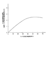
図6は、実施例1のリッチ溶液分岐供給率(%)と、CO2回収熱量削減率との関係を示す図である。ここで、リッチ溶液を分岐しない場合(分岐供給率0%)を基準としている。図6に示すように、分岐供給率が20%を超えると分岐効果が発現する。
FIG. 6 is a graph showing the relationship between the rich solution branch supply rate (%) and the CO 2 recovery heat amount reduction rate in Example 1. Here, the case where the rich solution is not branched (
図2は、実施例1に係る他のCO2回収装置の構成を示す概略図である。図2に示すように、実施例2に係るCO2回収装置10Bは、再生塔15内が3分割されており、第1分割部におけるセミリーン溶液19を第1液貯留部21aから抜き出すセミリーン溶液抜き出しラインL4を設けており、このセミリーン溶液抜き出しラインL4に分岐部18aを設けてセミリーン溶液19を分岐し、分岐したセミリーン溶液19の一部を分岐ラインL5により第2分割部の第2液貯留部21bに導入して、第2混合部20bとしている。
さらに、第2分割部15Bにおけるセミリーン溶液19を第2液貯留部21bから抜き出すセミリーン溶液抜き出しラインL6を設けており、このセミリーン溶液抜き出しラインL6に分岐部18bを設けてセミリーン溶液19を分岐し、分岐したセミリーン溶液19の一部を分岐ラインL7により第3分割部15Cの第3液貯留部21cに導入して、第3混合部20cとしている。
FIG. 2 is a schematic diagram illustrating the configuration of another CO 2 recovery device according to the first embodiment. As shown in FIG. 2, in the CO 2 recovery apparatus 10B according to the second embodiment, the inside of the
Further, a semi-lean solution extraction line L 6 for extracting the
このように、リーン・リッチ溶液熱交換器17で熱交換後のリッチ溶液14を分岐部18で分岐した後、さらにセミリーン溶液19を抜き出すセミリーン溶液抜き出しラインL4、L6に各々第1分岐部18a、第2分岐部18bを設け、セミリーン溶液の一部を第2液貯留部21b及び第3液貯留部21cに導入して混合するので、さらに再生塔15における分配効率が向上することとなる。
As described above, after the
本発明による実施例に係るCO2回収装置について、図3を参照して説明する。なお、実施例1の構成と同一部材には、同一符号を付して重複した説明は省略する。
図3は、実施例2に係るCO2回収装置の構成を示す概略図である。図3に示すように、実施例2に係るCO2回収装置10Cは、分割した吸収液再生塔15の上段側の前記セミリーン溶液19の第1液貯留部21aから、セミリーン溶液19を抜き出して吸収液再生塔15の下段側に供給するセミリーン溶液抜き出しラインL4を設け、このセミリーン溶液抜き出しラインL4に、分岐されたリッチ溶液14の一部14aを供給する分岐ラインL3の先端部を接続してライン混合部20Aを設け、分岐されたリッチ溶液14の一部14aとセミリーン溶液19とを混合するようにしている。
A CO 2 recovery apparatus according to an embodiment of the present invention will be described with reference to FIG. Note that the same members as those in the first embodiment are denoted by the same reference numerals, and redundant description is omitted.
FIG. 3 is a schematic diagram illustrating a configuration of the CO 2 recovery apparatus according to the second embodiment. As shown in FIG. 3, the CO 2 recovery apparatus 10C according to the second embodiment extracts and absorbs the
また、リーン溶液供給ラインL2に介装したリーン・リッチ溶液熱交換部17の前流側で、リーン溶液供給ラインL2とセミリーン溶液抜き出しラインL4との交差部にリーン・セミリーン溶液熱交換器51を設け、分岐されたリッチ溶液14の一部14aとセミリーン溶液19とをライン混合部20Aで混合した後に、この混合液をリーン・セミリーン溶液熱交換器51で、リーン溶液16と熱交換するようにしている。
Further, in the upstream side of the lean-solution supply line L 2 lean-rich
従来では、セミリーン溶液19をセミリーン溶液抜き出しラインL4を介して抜き出し、リーン・セミリーン溶液熱交換器51で熱交換して、セミリーン溶液19を加熱していたが、この場合、リーン溶液供給ラインL2の後流側に設置されるリーン・リッチ溶液熱交換部17での熱交換の熱が低下し、リッチ溶液14の保有する熱がCO2の放散負荷に対して熱足らずとなっていた。
これに対し、本実施例のように、分岐部18でリッチ溶液14の一部14aを分岐し、セミリーン溶液19と混合することで、リッチ溶液14を分配するので、CO2の放散負荷を均一化させ、再生エネルギーの省エネ化を図ることができる。
Conventionally, the
In contrast, as in this embodiment, branches a
図7は、実施例2のリッチ溶液分岐供給率(%)と、CO2回収熱量削減率との関係を示す図である。ここで、リッチ溶液を分岐しない場合(分岐供給率0%)を基準としている。図7に示すように、分岐供給率が20%を超えると分岐効果が発現する。
FIG. 7 is a diagram showing the relationship between the rich solution branch supply rate (%) and the CO 2 recovery heat amount reduction rate in Example 2. Here, the case where the rich solution is not branched (
本発明による実施例に係るCO2回収装置について、図4を参照して説明する。なお、実施例1の構成と同一部材には、同一符号を付して重複した説明は省略する。
図4は、実施例3に係るCO2回収装置の構成を示す概略図である。図4に示すように、実施例3に係るCO2回収装置10Dは、実施例2のCO2回収装置10Cにおいて、さらに再生塔15内が3分割されており、第1分割部15Aにおけるセミリーン溶液19を第1液貯留部21aから抜き出す第1セミリーン溶液抜き出しラインL4を設けていると共に、第2分割部15Bにおけるセミリーン溶液19を第2液貯留部21bから抜き出す第2セミリーン溶液抜き出しラインL6を設けている。
A CO 2 recovery apparatus according to an embodiment of the present invention will be described with reference to FIG. Note that the same members as those in the first embodiment are denoted by the same reference numerals, and redundant description is omitted.
FIG. 4 is a schematic diagram illustrating the configuration of the CO 2 recovery device according to the third embodiment. As shown in FIG. 4, in the CO 2 recovery apparatus 10D according to the third embodiment, the inside of the
また、この第1セミリーン溶液抜き出しラインL4及び第2セミリーン溶液抜き出しラインL6のセミリーン溶液19を、再生加熱器31のスチーム凝縮水35により熱交換するスチーム凝縮水・セミリーン溶液熱交換器52A、52Bを設けている。
Also, a steam condensed water / semi-lean
本実施例では、セミリーン溶液19が、スチーム凝縮水・セミリーン溶液熱交換器52A、52Bを通過後に、リーン溶液・セミリーン溶液熱交換器51A、51Bを各々通過するように、スチーム凝縮水・セミリーン溶液熱交換器52A、52B及びリーン溶液・セミリーン溶液熱交換器51A、51Bが、セミリーン溶液抜出しラインL4、L6に直列に介装される。
In the present embodiment, the steam-condensed water /
本実施例によれば、セミリーン溶液19をリッチ溶液14の一部14aと合流させた後に、スチーム凝縮水・セミリーン溶液熱交換器52A及びリーン溶液・セミリーン溶液熱交換器51Aで直列において熱交換するので、再生塔の塔頂側での過大なCO2の放散負荷の防止と熱分配の改良により、省エネ化を図ることができる。
According to the present embodiment, after the
図8は、実施例3のリッチ溶液分岐供給率(%)と、CO2回収熱量削減率との関係を示す図である。ここで、リッチ溶液を分岐しない場合(分岐供給率0%)を基準としている。図8に示すように、分岐供給率が20%を超えると分岐効果が発現する。
FIG. 8 is a diagram showing the relationship between the rich solution branch supply rate (%) and the CO 2 recovery heat amount reduction rate in Example 3. Here, the case where the rich solution is not branched (
本発明による実施例に係るCO2回収装置について、図5を参照して説明する。なお、実施例1の構成と同一部材には、同一符号を付して重複した説明は省略する。
図5に示すように、実施例4に係るCO2回収装置10Eは、実施例4において、さらに第1セミリーン溶液抜き出しラインL4及び第2セミリーン溶液抜き出しラインL6を分岐させて、第1セミリーン溶液抜き出しラインL4A及び第1セミリーン溶液抜き出しラインL4Bとすると共に、第2セミリーン溶液抜き出しラインL6A及び第2セミリーン溶液抜き出しラインL6Bとしている。
A CO 2 recovery apparatus according to an embodiment of the present invention will be described with reference to FIG. Note that the same members as those in the first embodiment are denoted by the same reference numerals, and redundant description is omitted.
As shown in FIG. 5, the CO 2 recovery apparatus 10E according to the fourth embodiment further branches the first semi-lean solution extraction line L 4 and the second semi-lean solution extraction line L 6 in the fourth embodiment. The solution extraction line L 4A and the first semi-lean solution extraction line L 4B are used, and the second semi-lean solution extraction line L 6A and the second semi-lean solution extraction line L 6B are used.
そして、第1セミリーン溶液抜き出しラインL4のライン混合部20Aの混合部の後流側で分岐した第1セミリーン溶液抜き出しラインL4Aにスチーム凝縮水・セミリーン溶液熱交換器52Aを介装すると共に、分岐した第2セミリーン溶液抜き出しラインL4Bにリーン溶液・セミリーン溶液熱交換器51Aを介装している。
スチーム凝縮水・セミリーン溶液熱交換器52A及びリーン溶液・セミリーン溶液熱交換器51Aで熱交換された後のセミリーン溶液は合流され、第2分割部15Bの第2液分散部15bに供給されている。
Then, the interposed first semi-lean solution extracting first semi-lean solution extracting steam condensate, the semi-lean
The semi-lean solution after heat exchange in the steam condensed water / semi-lean
同様に、第2セミリーン溶液抜き出しラインL6で分岐した第2セミリーン溶液抜き出しラインL6Aにスチーム凝縮水・セミリーン溶液熱交換器52Bを介装すると共に、分岐した第2セミリーン溶液抜き出しラインL6Bにリーン溶液・セミリーン溶液熱交換器51Bを介装している。
スチーム凝縮水・セミリーン溶液熱交換器52B及びリーン溶液・セミリーン溶液熱交換器51Bで熱交換された後のセミリーン溶液は合流され、第3分割部15Cの第3液分散部15cに供給されている。
Similarly, with interposed a steam-condensate-semi-lean
The semi-lean solution after heat exchange in the steam condensed water / semi-lean
本実施例によれば、セミリーン溶液19をリッチ溶液14の一部14aと合流させた後に、スチーム凝縮水・セミリーン溶液熱交換器52A及びリーン溶液・セミリーン溶液熱交換器51Aで並列において熱交換するので、再生塔の塔頂側での過大なCO2の放散負荷の防止と熱分配の改良により、省エネ化を図ることができる。
According to this embodiment, after the
10A〜10E CO2回収装置
11 CO2を含有するガス
12 CO2吸収液
13 CO2吸収塔(吸収塔)
14 リッチ溶液
15 吸収液再生塔(再生塔)
16 リーン溶液
20A ライン混合部
20a、20b 第1及び第2混合部
21a 第1液貯留部
21b 第2液貯留部
21c 第3液貯留部
10A to 10E CO 2 containing
14
16
Claims (4)
前記吸収液再生塔が少なくとも二分割してなり、
前記CO2吸収塔から前記吸収液再生塔にリッチ溶液を供給するリッチ溶液供給ラインと、
前記吸収液再生塔から前記CO2吸収塔にリーン溶液を供給するリーン溶液供給ラインと、
前記リーン溶液供給ラインと前記リッチ溶液供給ラインとの交差部に設けられ、リーン溶液とリッチ溶液とを熱交換するリーン・リッチ溶液熱交換器と、
前記リッチ溶液供給ラインのリーン・リッチ溶液熱交換器の後流側で、前記リッチ溶液の一部を分岐する分岐部と、
前記分岐部で分岐されたリッチ溶液の一部を、前記吸収液再生塔で前記リッチ溶液から一部のCO2が除去されたセミリーン溶液と混合する混合部とを具備してなり、且つ
分割した吸収液再生塔の上段側の前記セミリーン溶液の液貯留部に、前記分岐されたリッチ溶液の一部を供給する分岐ラインの先端部を接続し、分岐されたリッチ溶液の一部とセミリーン溶液とを混合することを特徴とするCO2回収装置。 CO 2 and contacting the gas and the CO 2 absorbing liquid containing includes a CO 2 absorption tower for removing CO 2, the absorbent regenerator to regenerate the rich solvent regeneration heater that has absorbed CO 2, A CO 2 recovery device for reusing a lean solution from which CO 2 has been removed in an absorption liquid regeneration tower as a CO 2 absorption liquid in a CO 2 absorption tower,
The absorption liquid regeneration tower is divided into at least two parts,
A rich solution supply line for supplying a rich solution from the CO 2 absorption tower to the absorption liquid regeneration tower;
A lean solution supply line for supplying a lean solution from the absorption liquid regeneration tower to the CO 2 absorption tower;
A lean / rich solution heat exchanger that is provided at an intersection of the lean solution supply line and the rich solution supply line to exchange heat between the lean solution and the rich solution;
A branching portion for branching a part of the rich solution on the downstream side of the lean / rich solution heat exchanger of the rich solution supply line;
Wherein a portion of the rich solution branched at the branch portion, Ri Na and and a mixing portion in which a part of the CO 2 is mixed with the semi-lean solution which is removed from the rich solution in the absorbing solution regeneration tower, and
A tip of a branch line for supplying a part of the branched rich solution is connected to the liquid storage part of the semi-lean solution on the upper side of the divided absorption liquid regeneration tower, and a part of the branched rich solution and the semi-lean A CO 2 recovery device characterized by mixing with a solution .
前記混合部が、
分割した吸収液再生塔の上段側の前記セミリーン溶液の液貯留部から、前記セミリーン溶液を抜き出して前記吸収液再生塔の下段側に供給するセミリーン溶液抜き出しラインを設け、
前記セミリーン溶液抜き出しラインに、前記分岐されたリッチ溶液の一部を供給する分岐ラインの先端部を接続して混合部を設け、分岐されたリッチ溶液の一部とセミリーン溶液とを混合することを特徴とするCO2回収装置。 In claim 1,
The mixing part is
A semi-lean solution extraction line for extracting the semi-lean solution from the liquid storage part of the semi-lean solution on the upper stage side of the divided absorption liquid regeneration tower and supplying it to the lower stage side of the absorption liquid regeneration tower is provided.
Connecting a tip of a branch line for supplying a part of the branched rich solution to the semi-lean solution extraction line to provide a mixing unit, and mixing the part of the branched rich solution with the semi-lean solution. Characteristic CO 2 recovery device.
前記リーン溶液供給ラインに介装したリーン・リッチ溶液熱交換部の前流側で、前記リーン溶液供給ラインと前記セミリーン溶液抜き出しラインとの交差部にリーン・セミリーン溶液熱交換器を設け、
前記分岐されたリッチ溶液の一部とセミリーン溶液とを混合部で混合した後に、混合液を前記リーン・セミリーン溶液熱交換器で、リーン溶液と熱交換することを特徴とするCO2回収装置。 In claim 2 ,
A lean / semi-lean solution heat exchanger is provided at the intersection of the lean solution supply line and the semi-lean solution extraction line on the upstream side of the lean / rich solution heat exchange unit interposed in the lean solution supply line,
A CO 2 recovery apparatus, wherein after mixing a part of the branched rich solution and a semi-lean solution in a mixing unit, the mixed solution is heat-exchanged with the lean solution by the lean / semi-lean solution heat exchanger.
前記セミリーン溶液抜き出しラインの前記混合部の後流側に介装され、前記吸収液再生塔の再生加熱器からのスチーム凝縮水の余熱により、分岐されたリッチ溶液の一部とセミリーン溶液との混合液を加熱するスチーム凝縮水熱交換器を設けることを特徴とするCO2回収装置。
In claim 3 ,
Mixing part of the rich solution branched with the semi-lean solution due to the residual heat of the steam condensate from the regeneration heater of the absorption liquid regeneration tower interposed in the downstream side of the mixing part of the semi-lean solution extraction line A CO 2 recovery device comprising a steam condensate heat exchanger for heating the liquid.
Priority Applications (6)
| Application Number | Priority Date | Filing Date | Title |
|---|---|---|---|
| JP2013215065A JP5863741B2 (en) | 2013-10-15 | 2013-10-15 | CO2 recovery device |
| CA2927094A CA2927094C (en) | 2013-10-15 | 2014-10-10 | Co2 recovery unit |
| US15/028,884 US9623365B2 (en) | 2013-10-15 | 2014-10-10 | CO2 recovery unit |
| PCT/JP2014/077265 WO2015056658A1 (en) | 2013-10-15 | 2014-10-10 | Co2 recovery device |
| AU2014335385A AU2014335385B2 (en) | 2013-10-15 | 2014-10-10 | CO2 recovery device |
| EP14853394.6A EP3045218A4 (en) | 2013-10-15 | 2014-10-10 | Co2 recovery device |
Applications Claiming Priority (1)
| Application Number | Priority Date | Filing Date | Title |
|---|---|---|---|
| JP2013215065A JP5863741B2 (en) | 2013-10-15 | 2013-10-15 | CO2 recovery device |
Publications (3)
| Publication Number | Publication Date |
|---|---|
| JP2015077538A JP2015077538A (en) | 2015-04-23 |
| JP2015077538A5 JP2015077538A5 (en) | 2015-06-18 |
| JP5863741B2 true JP5863741B2 (en) | 2016-02-17 |
Family
ID=52828102
Family Applications (1)
| Application Number | Title | Priority Date | Filing Date |
|---|---|---|---|
| JP2013215065A Active JP5863741B2 (en) | 2013-10-15 | 2013-10-15 | CO2 recovery device |
Country Status (6)
| Country | Link |
|---|---|
| US (1) | US9623365B2 (en) |
| EP (1) | EP3045218A4 (en) |
| JP (1) | JP5863741B2 (en) |
| AU (1) | AU2014335385B2 (en) |
| CA (1) | CA2927094C (en) |
| WO (1) | WO2015056658A1 (en) |
Families Citing this family (1)
| Publication number | Priority date | Publication date | Assignee | Title |
|---|---|---|---|---|
| US10456734B2 (en) * | 2016-11-01 | 2019-10-29 | Mitsubishi Heavy Industries Engineering, Ltd. | CO2 recovery system and method of recovering CO2 |
Family Cites Families (10)
| Publication number | Priority date | Publication date | Assignee | Title |
|---|---|---|---|---|
| JPH0751537A (en) * | 1993-06-30 | 1995-02-28 | Mitsubishi Heavy Ind Ltd | Removal of co2 in co2-containing gas |
| JP2005254121A (en) | 2004-03-11 | 2005-09-22 | Masaru Ichikawa | Manufacturing method of lower hydrocarbon direct-reforming catalyst |
| JP4690659B2 (en) * | 2004-03-15 | 2011-06-01 | 三菱重工業株式会社 | CO2 recovery device |
| JP5021917B2 (en) | 2005-09-01 | 2012-09-12 | 三菱重工業株式会社 | CO2 recovery apparatus and method |
| US8845789B2 (en) | 2009-03-31 | 2014-09-30 | Alstom Technology Ltd | Process for CO2 capture with improved stripper performance |
| PL2618914T3 (en) | 2010-09-20 | 2022-01-31 | Carbon Clean Solutions Limited | Solvent composition for carbon dioxide recovery |
| US8845790B2 (en) | 2011-01-06 | 2014-09-30 | Alstom Technology Ltd | Method and system for removal of gaseous contaminants |
| DE102011108308A1 (en) * | 2011-07-25 | 2013-01-31 | Thyssenkrupp Uhde Gmbh | Heat recovery in absorption and desorption processes with reduced heat exchange surface |
| JP5821531B2 (en) * | 2011-10-28 | 2015-11-24 | 株式会社Ihi | Carbon dioxide recovery method and recovery apparatus |
| JP5659176B2 (en) * | 2012-03-06 | 2015-01-28 | 株式会社東芝 | Carbon dioxide recovery device and carbon dioxide recovery method |
-
2013
- 2013-10-15 JP JP2013215065A patent/JP5863741B2/en active Active
-
2014
- 2014-10-10 CA CA2927094A patent/CA2927094C/en active Active
- 2014-10-10 AU AU2014335385A patent/AU2014335385B2/en active Active
- 2014-10-10 WO PCT/JP2014/077265 patent/WO2015056658A1/en active Application Filing
- 2014-10-10 EP EP14853394.6A patent/EP3045218A4/en not_active Ceased
- 2014-10-10 US US15/028,884 patent/US9623365B2/en active Active
Also Published As
| Publication number | Publication date |
|---|---|
| EP3045218A4 (en) | 2017-01-25 |
| CA2927094C (en) | 2018-05-01 |
| EP3045218A1 (en) | 2016-07-20 |
| JP2015077538A (en) | 2015-04-23 |
| US20160256816A1 (en) | 2016-09-08 |
| WO2015056658A1 (en) | 2015-04-23 |
| CA2927094A1 (en) | 2015-04-23 |
| US9623365B2 (en) | 2017-04-18 |
| AU2014335385A1 (en) | 2016-05-05 |
| AU2014335385B2 (en) | 2017-04-13 |
Similar Documents
| Publication | Publication Date | Title |
|---|---|---|
| JP4690659B2 (en) | CO2 recovery device | |
| JP5230088B2 (en) | CO2 recovery apparatus and method | |
| JP4745682B2 (en) | CO2 recovery apparatus and method | |
| JP5484811B2 (en) | Carbon dioxide recovery system and method | |
| JP5021917B2 (en) | CO2 recovery apparatus and method | |
| JP5922451B2 (en) | CO2 recovery device | |
| JP2005254212A5 (en) | ||
| JP5402842B2 (en) | Carbon dioxide recovery method and recovery apparatus | |
| JP4773865B2 (en) | CO2 recovery device and CO2 recovery method | |
| WO2013161574A1 (en) | Co2 recovery device, and co2 recovery method | |
| JP2008307520A (en) | Co2 or h2s removal system, co2 or h2s removal method | |
| JP5995746B2 (en) | CO2 and H2S containing gas recovery system and method | |
| JPWO2014024791A1 (en) | Exhaust gas treatment system | |
| JP5174194B2 (en) | CO2 recovery apparatus and method | |
| JP5738045B2 (en) | Carbon dioxide recovery system and method | |
| JP5591083B2 (en) | CO2 recovery system | |
| WO2011096250A1 (en) | System and method for recovering heat from co2 recovery device | |
| JP5737916B2 (en) | CO2 recovery system | |
| JP5863741B2 (en) | CO2 recovery device | |
| JP2008229496A (en) | Apparatus and method for separating/recovering carbon dioxide | |
| JP5518164B2 (en) | CO2 recovery apparatus and method | |
| Yonekawa et al. | CO 2 recovery apparatus | |
| Iijima et al. | CO 2 recovery system |
Legal Events
| Date | Code | Title | Description |
|---|---|---|---|
| A521 | Request for written amendment filed |
Free format text: JAPANESE INTERMEDIATE CODE: A523 Effective date: 20150423 |
|
| A621 | Written request for application examination |
Free format text: JAPANESE INTERMEDIATE CODE: A621 Effective date: 20150423 |
|
| TRDD | Decision of grant or rejection written | ||
| A01 | Written decision to grant a patent or to grant a registration (utility model) |
Free format text: JAPANESE INTERMEDIATE CODE: A01 Effective date: 20151124 |
|
| A61 | First payment of annual fees (during grant procedure) |
Free format text: JAPANESE INTERMEDIATE CODE: A61 Effective date: 20151222 |
|
| R150 | Certificate of patent or registration of utility model |
Ref document number: 5863741 Country of ref document: JP Free format text: JAPANESE INTERMEDIATE CODE: R150 |
|
| S111 | Request for change of ownership or part of ownership |
Free format text: JAPANESE INTERMEDIATE CODE: R313115 |
|
| R350 | Written notification of registration of transfer |
Free format text: JAPANESE INTERMEDIATE CODE: R350 |
|
| R250 | Receipt of annual fees |
Free format text: JAPANESE INTERMEDIATE CODE: R250 |
|
| R250 | Receipt of annual fees |
Free format text: JAPANESE INTERMEDIATE CODE: R250 |
|
| R250 | Receipt of annual fees |
Free format text: JAPANESE INTERMEDIATE CODE: R250 |
|
| R250 | Receipt of annual fees |
Free format text: JAPANESE INTERMEDIATE CODE: R250 |
|
| R250 | Receipt of annual fees |
Free format text: JAPANESE INTERMEDIATE CODE: R250 |
|
| S533 | Written request for registration of change of name |
Free format text: JAPANESE INTERMEDIATE CODE: R313533 |
|
| R350 | Written notification of registration of transfer |
Free format text: JAPANESE INTERMEDIATE CODE: R350 |
|
| S111 | Request for change of ownership or part of ownership |
Free format text: JAPANESE INTERMEDIATE CODE: R313115 |
|
| R350 | Written notification of registration of transfer |
Free format text: JAPANESE INTERMEDIATE CODE: R350 |
|
| R250 | Receipt of annual fees |
Free format text: JAPANESE INTERMEDIATE CODE: R250 |