JP5861444B2 - Secondary battery active material, secondary battery and electronic equipment - Google Patents
Secondary battery active material, secondary battery and electronic equipment Download PDFInfo
- Publication number
- JP5861444B2 JP5861444B2 JP2011278526A JP2011278526A JP5861444B2 JP 5861444 B2 JP5861444 B2 JP 5861444B2 JP 2011278526 A JP2011278526 A JP 2011278526A JP 2011278526 A JP2011278526 A JP 2011278526A JP 5861444 B2 JP5861444 B2 JP 5861444B2
- Authority
- JP
- Japan
- Prior art keywords
- active material
- negative electrode
- secondary battery
- atomic
- atomic ratio
- Prior art date
- Legal status (The legal status is an assumption and is not a legal conclusion. Google has not performed a legal analysis and makes no representation as to the accuracy of the status listed.)
- Active
Links
Images


Classifications
-
- H—ELECTRICITY
- H01—ELECTRIC ELEMENTS
- H01M—PROCESSES OR MEANS, e.g. BATTERIES, FOR THE DIRECT CONVERSION OF CHEMICAL ENERGY INTO ELECTRICAL ENERGY
- H01M4/00—Electrodes
- H01M4/02—Electrodes composed of, or comprising, active material
- H01M4/36—Selection of substances as active materials, active masses, active liquids
- H01M4/362—Composites
- H01M4/366—Composites as layered products
-
- B—PERFORMING OPERATIONS; TRANSPORTING
- B60—VEHICLES IN GENERAL
- B60L—PROPULSION OF ELECTRICALLY-PROPELLED VEHICLES; SUPPLYING ELECTRIC POWER FOR AUXILIARY EQUIPMENT OF ELECTRICALLY-PROPELLED VEHICLES; ELECTRODYNAMIC BRAKE SYSTEMS FOR VEHICLES IN GENERAL; MAGNETIC SUSPENSION OR LEVITATION FOR VEHICLES; MONITORING OPERATING VARIABLES OF ELECTRICALLY-PROPELLED VEHICLES; ELECTRIC SAFETY DEVICES FOR ELECTRICALLY-PROPELLED VEHICLES
- B60L3/00—Electric devices on electrically-propelled vehicles for safety purposes; Monitoring operating variables, e.g. speed, deceleration or energy consumption
- B60L3/0023—Detecting, eliminating, remedying or compensating for drive train abnormalities, e.g. failures within the drive train
- B60L3/0046—Detecting, eliminating, remedying or compensating for drive train abnormalities, e.g. failures within the drive train relating to electric energy storage systems, e.g. batteries or capacitors
-
- B—PERFORMING OPERATIONS; TRANSPORTING
- B60—VEHICLES IN GENERAL
- B60L—PROPULSION OF ELECTRICALLY-PROPELLED VEHICLES; SUPPLYING ELECTRIC POWER FOR AUXILIARY EQUIPMENT OF ELECTRICALLY-PROPELLED VEHICLES; ELECTRODYNAMIC BRAKE SYSTEMS FOR VEHICLES IN GENERAL; MAGNETIC SUSPENSION OR LEVITATION FOR VEHICLES; MONITORING OPERATING VARIABLES OF ELECTRICALLY-PROPELLED VEHICLES; ELECTRIC SAFETY DEVICES FOR ELECTRICALLY-PROPELLED VEHICLES
- B60L50/00—Electric propulsion with power supplied within the vehicle
- B60L50/10—Electric propulsion with power supplied within the vehicle using propulsion power supplied by engine-driven generators, e.g. generators driven by combustion engines
- B60L50/16—Electric propulsion with power supplied within the vehicle using propulsion power supplied by engine-driven generators, e.g. generators driven by combustion engines with provision for separate direct mechanical propulsion
-
- B—PERFORMING OPERATIONS; TRANSPORTING
- B60—VEHICLES IN GENERAL
- B60L—PROPULSION OF ELECTRICALLY-PROPELLED VEHICLES; SUPPLYING ELECTRIC POWER FOR AUXILIARY EQUIPMENT OF ELECTRICALLY-PROPELLED VEHICLES; ELECTRODYNAMIC BRAKE SYSTEMS FOR VEHICLES IN GENERAL; MAGNETIC SUSPENSION OR LEVITATION FOR VEHICLES; MONITORING OPERATING VARIABLES OF ELECTRICALLY-PROPELLED VEHICLES; ELECTRIC SAFETY DEVICES FOR ELECTRICALLY-PROPELLED VEHICLES
- B60L50/00—Electric propulsion with power supplied within the vehicle
- B60L50/50—Electric propulsion with power supplied within the vehicle using propulsion power supplied by batteries or fuel cells
- B60L50/60—Electric propulsion with power supplied within the vehicle using propulsion power supplied by batteries or fuel cells using power supplied by batteries
- B60L50/66—Arrangements of batteries
-
- B—PERFORMING OPERATIONS; TRANSPORTING
- B60—VEHICLES IN GENERAL
- B60L—PROPULSION OF ELECTRICALLY-PROPELLED VEHICLES; SUPPLYING ELECTRIC POWER FOR AUXILIARY EQUIPMENT OF ELECTRICALLY-PROPELLED VEHICLES; ELECTRODYNAMIC BRAKE SYSTEMS FOR VEHICLES IN GENERAL; MAGNETIC SUSPENSION OR LEVITATION FOR VEHICLES; MONITORING OPERATING VARIABLES OF ELECTRICALLY-PROPELLED VEHICLES; ELECTRIC SAFETY DEVICES FOR ELECTRICALLY-PROPELLED VEHICLES
- B60L53/00—Methods of charging batteries, specially adapted for electric vehicles; Charging stations or on-board charging equipment therefor; Exchange of energy storage elements in electric vehicles
- B60L53/50—Charging stations characterised by energy-storage or power-generation means
- B60L53/53—Batteries
-
- B—PERFORMING OPERATIONS; TRANSPORTING
- B60—VEHICLES IN GENERAL
- B60L—PROPULSION OF ELECTRICALLY-PROPELLED VEHICLES; SUPPLYING ELECTRIC POWER FOR AUXILIARY EQUIPMENT OF ELECTRICALLY-PROPELLED VEHICLES; ELECTRODYNAMIC BRAKE SYSTEMS FOR VEHICLES IN GENERAL; MAGNETIC SUSPENSION OR LEVITATION FOR VEHICLES; MONITORING OPERATING VARIABLES OF ELECTRICALLY-PROPELLED VEHICLES; ELECTRIC SAFETY DEVICES FOR ELECTRICALLY-PROPELLED VEHICLES
- B60L53/00—Methods of charging batteries, specially adapted for electric vehicles; Charging stations or on-board charging equipment therefor; Exchange of energy storage elements in electric vehicles
- B60L53/50—Charging stations characterised by energy-storage or power-generation means
- B60L53/57—Charging stations without connection to power networks
-
- B—PERFORMING OPERATIONS; TRANSPORTING
- B60—VEHICLES IN GENERAL
- B60L—PROPULSION OF ELECTRICALLY-PROPELLED VEHICLES; SUPPLYING ELECTRIC POWER FOR AUXILIARY EQUIPMENT OF ELECTRICALLY-PROPELLED VEHICLES; ELECTRODYNAMIC BRAKE SYSTEMS FOR VEHICLES IN GENERAL; MAGNETIC SUSPENSION OR LEVITATION FOR VEHICLES; MONITORING OPERATING VARIABLES OF ELECTRICALLY-PROPELLED VEHICLES; ELECTRIC SAFETY DEVICES FOR ELECTRICALLY-PROPELLED VEHICLES
- B60L53/00—Methods of charging batteries, specially adapted for electric vehicles; Charging stations or on-board charging equipment therefor; Exchange of energy storage elements in electric vehicles
- B60L53/60—Monitoring or controlling charging stations
- B60L53/65—Monitoring or controlling charging stations involving identification of vehicles or their battery types
-
- B—PERFORMING OPERATIONS; TRANSPORTING
- B60—VEHICLES IN GENERAL
- B60L—PROPULSION OF ELECTRICALLY-PROPELLED VEHICLES; SUPPLYING ELECTRIC POWER FOR AUXILIARY EQUIPMENT OF ELECTRICALLY-PROPELLED VEHICLES; ELECTRODYNAMIC BRAKE SYSTEMS FOR VEHICLES IN GENERAL; MAGNETIC SUSPENSION OR LEVITATION FOR VEHICLES; MONITORING OPERATING VARIABLES OF ELECTRICALLY-PROPELLED VEHICLES; ELECTRIC SAFETY DEVICES FOR ELECTRICALLY-PROPELLED VEHICLES
- B60L55/00—Arrangements for supplying energy stored within a vehicle to a power network, i.e. vehicle-to-grid [V2G] arrangements
-
- B—PERFORMING OPERATIONS; TRANSPORTING
- B60—VEHICLES IN GENERAL
- B60L—PROPULSION OF ELECTRICALLY-PROPELLED VEHICLES; SUPPLYING ELECTRIC POWER FOR AUXILIARY EQUIPMENT OF ELECTRICALLY-PROPELLED VEHICLES; ELECTRODYNAMIC BRAKE SYSTEMS FOR VEHICLES IN GENERAL; MAGNETIC SUSPENSION OR LEVITATION FOR VEHICLES; MONITORING OPERATING VARIABLES OF ELECTRICALLY-PROPELLED VEHICLES; ELECTRIC SAFETY DEVICES FOR ELECTRICALLY-PROPELLED VEHICLES
- B60L58/00—Methods or circuit arrangements for monitoring or controlling batteries or fuel cells, specially adapted for electric vehicles
- B60L58/10—Methods or circuit arrangements for monitoring or controlling batteries or fuel cells, specially adapted for electric vehicles for monitoring or controlling batteries
- B60L58/12—Methods or circuit arrangements for monitoring or controlling batteries or fuel cells, specially adapted for electric vehicles for monitoring or controlling batteries responding to state of charge [SoC]
- B60L58/15—Preventing overcharging
-
- B—PERFORMING OPERATIONS; TRANSPORTING
- B60—VEHICLES IN GENERAL
- B60L—PROPULSION OF ELECTRICALLY-PROPELLED VEHICLES; SUPPLYING ELECTRIC POWER FOR AUXILIARY EQUIPMENT OF ELECTRICALLY-PROPELLED VEHICLES; ELECTRODYNAMIC BRAKE SYSTEMS FOR VEHICLES IN GENERAL; MAGNETIC SUSPENSION OR LEVITATION FOR VEHICLES; MONITORING OPERATING VARIABLES OF ELECTRICALLY-PROPELLED VEHICLES; ELECTRIC SAFETY DEVICES FOR ELECTRICALLY-PROPELLED VEHICLES
- B60L58/00—Methods or circuit arrangements for monitoring or controlling batteries or fuel cells, specially adapted for electric vehicles
- B60L58/10—Methods or circuit arrangements for monitoring or controlling batteries or fuel cells, specially adapted for electric vehicles for monitoring or controlling batteries
- B60L58/24—Methods or circuit arrangements for monitoring or controlling batteries or fuel cells, specially adapted for electric vehicles for monitoring or controlling batteries for controlling the temperature of batteries
- B60L58/27—Methods or circuit arrangements for monitoring or controlling batteries or fuel cells, specially adapted for electric vehicles for monitoring or controlling batteries for controlling the temperature of batteries by heating
-
- B—PERFORMING OPERATIONS; TRANSPORTING
- B60—VEHICLES IN GENERAL
- B60L—PROPULSION OF ELECTRICALLY-PROPELLED VEHICLES; SUPPLYING ELECTRIC POWER FOR AUXILIARY EQUIPMENT OF ELECTRICALLY-PROPELLED VEHICLES; ELECTRODYNAMIC BRAKE SYSTEMS FOR VEHICLES IN GENERAL; MAGNETIC SUSPENSION OR LEVITATION FOR VEHICLES; MONITORING OPERATING VARIABLES OF ELECTRICALLY-PROPELLED VEHICLES; ELECTRIC SAFETY DEVICES FOR ELECTRICALLY-PROPELLED VEHICLES
- B60L7/00—Electrodynamic brake systems for vehicles in general
- B60L7/10—Dynamic electric regenerative braking
- B60L7/14—Dynamic electric regenerative braking for vehicles propelled by ac motors
-
- H—ELECTRICITY
- H01—ELECTRIC ELEMENTS
- H01M—PROCESSES OR MEANS, e.g. BATTERIES, FOR THE DIRECT CONVERSION OF CHEMICAL ENERGY INTO ELECTRICAL ENERGY
- H01M10/00—Secondary cells; Manufacture thereof
- H01M10/05—Accumulators with non-aqueous electrolyte
- H01M10/052—Li-accumulators
- H01M10/0525—Rocking-chair batteries, i.e. batteries with lithium insertion or intercalation in both electrodes; Lithium-ion batteries
-
- H—ELECTRICITY
- H01—ELECTRIC ELEMENTS
- H01M—PROCESSES OR MEANS, e.g. BATTERIES, FOR THE DIRECT CONVERSION OF CHEMICAL ENERGY INTO ELECTRICAL ENERGY
- H01M4/00—Electrodes
- H01M4/02—Electrodes composed of, or comprising, active material
- H01M4/13—Electrodes for accumulators with non-aqueous electrolyte, e.g. for lithium-accumulators; Processes of manufacture thereof
- H01M4/131—Electrodes based on mixed oxides or hydroxides, or on mixtures of oxides or hydroxides, e.g. LiCoOx
-
- H—ELECTRICITY
- H01—ELECTRIC ELEMENTS
- H01M—PROCESSES OR MEANS, e.g. BATTERIES, FOR THE DIRECT CONVERSION OF CHEMICAL ENERGY INTO ELECTRICAL ENERGY
- H01M4/00—Electrodes
- H01M4/02—Electrodes composed of, or comprising, active material
- H01M4/36—Selection of substances as active materials, active masses, active liquids
- H01M4/48—Selection of substances as active materials, active masses, active liquids of inorganic oxides or hydroxides
- H01M4/483—Selection of substances as active materials, active masses, active liquids of inorganic oxides or hydroxides for non-aqueous cells
-
- H—ELECTRICITY
- H01—ELECTRIC ELEMENTS
- H01M—PROCESSES OR MEANS, e.g. BATTERIES, FOR THE DIRECT CONVERSION OF CHEMICAL ENERGY INTO ELECTRICAL ENERGY
- H01M4/00—Electrodes
- H01M4/02—Electrodes composed of, or comprising, active material
- H01M4/36—Selection of substances as active materials, active masses, active liquids
- H01M4/48—Selection of substances as active materials, active masses, active liquids of inorganic oxides or hydroxides
- H01M4/485—Selection of substances as active materials, active masses, active liquids of inorganic oxides or hydroxides of mixed oxides or hydroxides for inserting or intercalating light metals, e.g. LiTi2O4 or LiTi2OxFy
-
- H—ELECTRICITY
- H01—ELECTRIC ELEMENTS
- H01M—PROCESSES OR MEANS, e.g. BATTERIES, FOR THE DIRECT CONVERSION OF CHEMICAL ENERGY INTO ELECTRICAL ENERGY
- H01M4/00—Electrodes
- H01M4/02—Electrodes composed of, or comprising, active material
- H01M4/36—Selection of substances as active materials, active masses, active liquids
- H01M4/58—Selection of substances as active materials, active masses, active liquids of inorganic compounds other than oxides or hydroxides, e.g. sulfides, selenides, tellurides, halogenides or LiCoFy; of polyanionic structures, e.g. phosphates, silicates or borates
- H01M4/583—Carbonaceous material, e.g. graphite-intercalation compounds or CFx
- H01M4/587—Carbonaceous material, e.g. graphite-intercalation compounds or CFx for inserting or intercalating light metals
-
- H—ELECTRICITY
- H01—ELECTRIC ELEMENTS
- H01M—PROCESSES OR MEANS, e.g. BATTERIES, FOR THE DIRECT CONVERSION OF CHEMICAL ENERGY INTO ELECTRICAL ENERGY
- H01M4/00—Electrodes
- H01M4/02—Electrodes composed of, or comprising, active material
- H01M4/62—Selection of inactive substances as ingredients for active masses, e.g. binders, fillers
- H01M4/624—Electric conductive fillers
- H01M4/625—Carbon or graphite
-
- B—PERFORMING OPERATIONS; TRANSPORTING
- B60—VEHICLES IN GENERAL
- B60L—PROPULSION OF ELECTRICALLY-PROPELLED VEHICLES; SUPPLYING ELECTRIC POWER FOR AUXILIARY EQUIPMENT OF ELECTRICALLY-PROPELLED VEHICLES; ELECTRODYNAMIC BRAKE SYSTEMS FOR VEHICLES IN GENERAL; MAGNETIC SUSPENSION OR LEVITATION FOR VEHICLES; MONITORING OPERATING VARIABLES OF ELECTRICALLY-PROPELLED VEHICLES; ELECTRIC SAFETY DEVICES FOR ELECTRICALLY-PROPELLED VEHICLES
- B60L2210/00—Converter types
- B60L2210/40—DC to AC converters
-
- B—PERFORMING OPERATIONS; TRANSPORTING
- B60—VEHICLES IN GENERAL
- B60L—PROPULSION OF ELECTRICALLY-PROPELLED VEHICLES; SUPPLYING ELECTRIC POWER FOR AUXILIARY EQUIPMENT OF ELECTRICALLY-PROPELLED VEHICLES; ELECTRODYNAMIC BRAKE SYSTEMS FOR VEHICLES IN GENERAL; MAGNETIC SUSPENSION OR LEVITATION FOR VEHICLES; MONITORING OPERATING VARIABLES OF ELECTRICALLY-PROPELLED VEHICLES; ELECTRIC SAFETY DEVICES FOR ELECTRICALLY-PROPELLED VEHICLES
- B60L2240/00—Control parameters of input or output; Target parameters
- B60L2240/40—Drive Train control parameters
- B60L2240/54—Drive Train control parameters related to batteries
- B60L2240/545—Temperature
-
- B—PERFORMING OPERATIONS; TRANSPORTING
- B60—VEHICLES IN GENERAL
- B60L—PROPULSION OF ELECTRICALLY-PROPELLED VEHICLES; SUPPLYING ELECTRIC POWER FOR AUXILIARY EQUIPMENT OF ELECTRICALLY-PROPELLED VEHICLES; ELECTRODYNAMIC BRAKE SYSTEMS FOR VEHICLES IN GENERAL; MAGNETIC SUSPENSION OR LEVITATION FOR VEHICLES; MONITORING OPERATING VARIABLES OF ELECTRICALLY-PROPELLED VEHICLES; ELECTRIC SAFETY DEVICES FOR ELECTRICALLY-PROPELLED VEHICLES
- B60L2240/00—Control parameters of input or output; Target parameters
- B60L2240/40—Drive Train control parameters
- B60L2240/54—Drive Train control parameters related to batteries
- B60L2240/547—Voltage
-
- B—PERFORMING OPERATIONS; TRANSPORTING
- B60—VEHICLES IN GENERAL
- B60L—PROPULSION OF ELECTRICALLY-PROPELLED VEHICLES; SUPPLYING ELECTRIC POWER FOR AUXILIARY EQUIPMENT OF ELECTRICALLY-PROPELLED VEHICLES; ELECTRODYNAMIC BRAKE SYSTEMS FOR VEHICLES IN GENERAL; MAGNETIC SUSPENSION OR LEVITATION FOR VEHICLES; MONITORING OPERATING VARIABLES OF ELECTRICALLY-PROPELLED VEHICLES; ELECTRIC SAFETY DEVICES FOR ELECTRICALLY-PROPELLED VEHICLES
- B60L2240/00—Control parameters of input or output; Target parameters
- B60L2240/40—Drive Train control parameters
- B60L2240/54—Drive Train control parameters related to batteries
- B60L2240/549—Current
-
- H—ELECTRICITY
- H01—ELECTRIC ELEMENTS
- H01M—PROCESSES OR MEANS, e.g. BATTERIES, FOR THE DIRECT CONVERSION OF CHEMICAL ENERGY INTO ELECTRICAL ENERGY
- H01M4/00—Electrodes
- H01M4/02—Electrodes composed of, or comprising, active material
- H01M2004/026—Electrodes composed of, or comprising, active material characterised by the polarity
- H01M2004/027—Negative electrodes
-
- Y—GENERAL TAGGING OF NEW TECHNOLOGICAL DEVELOPMENTS; GENERAL TAGGING OF CROSS-SECTIONAL TECHNOLOGIES SPANNING OVER SEVERAL SECTIONS OF THE IPC; TECHNICAL SUBJECTS COVERED BY FORMER USPC CROSS-REFERENCE ART COLLECTIONS [XRACs] AND DIGESTS
- Y02—TECHNOLOGIES OR APPLICATIONS FOR MITIGATION OR ADAPTATION AGAINST CLIMATE CHANGE
- Y02E—REDUCTION OF GREENHOUSE GAS [GHG] EMISSIONS, RELATED TO ENERGY GENERATION, TRANSMISSION OR DISTRIBUTION
- Y02E60/00—Enabling technologies; Technologies with a potential or indirect contribution to GHG emissions mitigation
- Y02E60/10—Energy storage using batteries
-
- Y—GENERAL TAGGING OF NEW TECHNOLOGICAL DEVELOPMENTS; GENERAL TAGGING OF CROSS-SECTIONAL TECHNOLOGIES SPANNING OVER SEVERAL SECTIONS OF THE IPC; TECHNICAL SUBJECTS COVERED BY FORMER USPC CROSS-REFERENCE ART COLLECTIONS [XRACs] AND DIGESTS
- Y02—TECHNOLOGIES OR APPLICATIONS FOR MITIGATION OR ADAPTATION AGAINST CLIMATE CHANGE
- Y02T—CLIMATE CHANGE MITIGATION TECHNOLOGIES RELATED TO TRANSPORTATION
- Y02T10/00—Road transport of goods or passengers
- Y02T10/60—Other road transportation technologies with climate change mitigation effect
- Y02T10/70—Energy storage systems for electromobility, e.g. batteries
-
- Y—GENERAL TAGGING OF NEW TECHNOLOGICAL DEVELOPMENTS; GENERAL TAGGING OF CROSS-SECTIONAL TECHNOLOGIES SPANNING OVER SEVERAL SECTIONS OF THE IPC; TECHNICAL SUBJECTS COVERED BY FORMER USPC CROSS-REFERENCE ART COLLECTIONS [XRACs] AND DIGESTS
- Y02—TECHNOLOGIES OR APPLICATIONS FOR MITIGATION OR ADAPTATION AGAINST CLIMATE CHANGE
- Y02T—CLIMATE CHANGE MITIGATION TECHNOLOGIES RELATED TO TRANSPORTATION
- Y02T10/00—Road transport of goods or passengers
- Y02T10/60—Other road transportation technologies with climate change mitigation effect
- Y02T10/7072—Electromobility specific charging systems or methods for batteries, ultracapacitors, supercapacitors or double-layer capacitors
-
- Y—GENERAL TAGGING OF NEW TECHNOLOGICAL DEVELOPMENTS; GENERAL TAGGING OF CROSS-SECTIONAL TECHNOLOGIES SPANNING OVER SEVERAL SECTIONS OF THE IPC; TECHNICAL SUBJECTS COVERED BY FORMER USPC CROSS-REFERENCE ART COLLECTIONS [XRACs] AND DIGESTS
- Y02—TECHNOLOGIES OR APPLICATIONS FOR MITIGATION OR ADAPTATION AGAINST CLIMATE CHANGE
- Y02T—CLIMATE CHANGE MITIGATION TECHNOLOGIES RELATED TO TRANSPORTATION
- Y02T10/00—Road transport of goods or passengers
- Y02T10/60—Other road transportation technologies with climate change mitigation effect
- Y02T10/72—Electric energy management in electromobility
-
- Y—GENERAL TAGGING OF NEW TECHNOLOGICAL DEVELOPMENTS; GENERAL TAGGING OF CROSS-SECTIONAL TECHNOLOGIES SPANNING OVER SEVERAL SECTIONS OF THE IPC; TECHNICAL SUBJECTS COVERED BY FORMER USPC CROSS-REFERENCE ART COLLECTIONS [XRACs] AND DIGESTS
- Y02—TECHNOLOGIES OR APPLICATIONS FOR MITIGATION OR ADAPTATION AGAINST CLIMATE CHANGE
- Y02T—CLIMATE CHANGE MITIGATION TECHNOLOGIES RELATED TO TRANSPORTATION
- Y02T90/00—Enabling technologies or technologies with a potential or indirect contribution to GHG emissions mitigation
- Y02T90/10—Technologies relating to charging of electric vehicles
- Y02T90/12—Electric charging stations
-
- Y—GENERAL TAGGING OF NEW TECHNOLOGICAL DEVELOPMENTS; GENERAL TAGGING OF CROSS-SECTIONAL TECHNOLOGIES SPANNING OVER SEVERAL SECTIONS OF THE IPC; TECHNICAL SUBJECTS COVERED BY FORMER USPC CROSS-REFERENCE ART COLLECTIONS [XRACs] AND DIGESTS
- Y02—TECHNOLOGIES OR APPLICATIONS FOR MITIGATION OR ADAPTATION AGAINST CLIMATE CHANGE
- Y02T—CLIMATE CHANGE MITIGATION TECHNOLOGIES RELATED TO TRANSPORTATION
- Y02T90/00—Enabling technologies or technologies with a potential or indirect contribution to GHG emissions mitigation
- Y02T90/10—Technologies relating to charging of electric vehicles
- Y02T90/14—Plug-in electric vehicles
-
- Y—GENERAL TAGGING OF NEW TECHNOLOGICAL DEVELOPMENTS; GENERAL TAGGING OF CROSS-SECTIONAL TECHNOLOGIES SPANNING OVER SEVERAL SECTIONS OF THE IPC; TECHNICAL SUBJECTS COVERED BY FORMER USPC CROSS-REFERENCE ART COLLECTIONS [XRACs] AND DIGESTS
- Y02—TECHNOLOGIES OR APPLICATIONS FOR MITIGATION OR ADAPTATION AGAINST CLIMATE CHANGE
- Y02T—CLIMATE CHANGE MITIGATION TECHNOLOGIES RELATED TO TRANSPORTATION
- Y02T90/00—Enabling technologies or technologies with a potential or indirect contribution to GHG emissions mitigation
- Y02T90/10—Technologies relating to charging of electric vehicles
- Y02T90/16—Information or communication technologies improving the operation of electric vehicles
- Y02T90/167—Systems integrating technologies related to power network operation and communication or information technologies for supporting the interoperability of electric or hybrid vehicles, i.e. smartgrids as interface for battery charging of electric vehicles [EV] or hybrid vehicles [HEV]
-
- Y—GENERAL TAGGING OF NEW TECHNOLOGICAL DEVELOPMENTS; GENERAL TAGGING OF CROSS-SECTIONAL TECHNOLOGIES SPANNING OVER SEVERAL SECTIONS OF THE IPC; TECHNICAL SUBJECTS COVERED BY FORMER USPC CROSS-REFERENCE ART COLLECTIONS [XRACs] AND DIGESTS
- Y04—INFORMATION OR COMMUNICATION TECHNOLOGIES HAVING AN IMPACT ON OTHER TECHNOLOGY AREAS
- Y04S—SYSTEMS INTEGRATING TECHNOLOGIES RELATED TO POWER NETWORK OPERATION, COMMUNICATION OR INFORMATION TECHNOLOGIES FOR IMPROVING THE ELECTRICAL POWER GENERATION, TRANSMISSION, DISTRIBUTION, MANAGEMENT OR USAGE, i.e. SMART GRIDS
- Y04S10/00—Systems supporting electrical power generation, transmission or distribution
- Y04S10/12—Monitoring or controlling equipment for energy generation units, e.g. distributed energy generation [DER] or load-side generation
- Y04S10/126—Monitoring or controlling equipment for energy generation units, e.g. distributed energy generation [DER] or load-side generation the energy generation units being or involving electric vehicles [EV] or hybrid vehicles [HEV], i.e. power aggregation of EV or HEV, vehicle to grid arrangements [V2G]
-
- Y—GENERAL TAGGING OF NEW TECHNOLOGICAL DEVELOPMENTS; GENERAL TAGGING OF CROSS-SECTIONAL TECHNOLOGIES SPANNING OVER SEVERAL SECTIONS OF THE IPC; TECHNICAL SUBJECTS COVERED BY FORMER USPC CROSS-REFERENCE ART COLLECTIONS [XRACs] AND DIGESTS
- Y04—INFORMATION OR COMMUNICATION TECHNOLOGIES HAVING AN IMPACT ON OTHER TECHNOLOGY AREAS
- Y04S—SYSTEMS INTEGRATING TECHNOLOGIES RELATED TO POWER NETWORK OPERATION, COMMUNICATION OR INFORMATION TECHNOLOGIES FOR IMPROVING THE ELECTRICAL POWER GENERATION, TRANSMISSION, DISTRIBUTION, MANAGEMENT OR USAGE, i.e. SMART GRIDS
- Y04S30/00—Systems supporting specific end-user applications in the sector of transportation
- Y04S30/10—Systems supporting the interoperability of electric or hybrid vehicles
- Y04S30/14—Details associated with the interoperability, e.g. vehicle recognition, authentication, identification or billing
Landscapes
- Engineering & Computer Science (AREA)
- Chemical & Material Sciences (AREA)
- Power Engineering (AREA)
- Mechanical Engineering (AREA)
- Transportation (AREA)
- Chemical Kinetics & Catalysis (AREA)
- Electrochemistry (AREA)
- General Chemical & Material Sciences (AREA)
- Sustainable Development (AREA)
- Life Sciences & Earth Sciences (AREA)
- Sustainable Energy (AREA)
- Inorganic Chemistry (AREA)
- Composite Materials (AREA)
- Materials Engineering (AREA)
- Manufacturing & Machinery (AREA)
- Battery Electrode And Active Subsutance (AREA)
- Secondary Cells (AREA)
- Silicon Compounds (AREA)
- Cell Electrode Carriers And Collectors (AREA)
- Physics & Mathematics (AREA)
- Condensed Matter Physics & Semiconductors (AREA)
- General Physics & Mathematics (AREA)
Description
本技術は、リチウムイオンを吸蔵放出可能である二次電池用活物質、その活物質を用いた二次電池、およびその二次電池を用いた電子機器に関する。 The present technology relates to an active material for a secondary battery capable of occluding and releasing lithium ions, a secondary battery using the active material, and an electronic device using the secondary battery.
近年、携帯電話機または携帯情報端末機器(PDA)などに代表される電子機器が広く普及しており、そのさらなる小型化、軽量化および長寿命化が強く求められている。これに伴い、電源として、電池、特に小型かつ軽量で高エネルギー密度を得ることが可能な二次電池の開発が進められている。この二次電池は、最近では、上記した電子機器に限らず、着脱可能な電源である電池パック、電気自動車などの電動車両、家庭用電力サーバなどの電力貯蔵システム、または電動ドリルなどの電動工具に代表される多様な用途への適用も検討されている。 In recent years, electronic devices typified by mobile phones or personal digital assistants (PDAs) have become widespread, and further downsizing, weight reduction, and long life have been strongly demanded. Accordingly, as a power source, development of a battery, in particular, a secondary battery that is small and lightweight and capable of obtaining a high energy density is in progress. Recently, the secondary battery is not limited to the above-described electronic device, but is a battery pack that is a detachable power source, an electric vehicle such as an electric vehicle, an electric power storage system such as a household electric power server, or an electric tool such as an electric drill. Application to various uses represented by
二次電池としては、さまざまな充放電原理を利用するものが広く提案されているが、中でも、リチウムイオンなどの吸蔵放出を利用するものが有望視されている。鉛電池およびニッケルカドミウム電池などよりも高いエネルギー密度が得られるからである。 As secondary batteries, those using various charge / discharge principles have been widely proposed, and among them, those using occlusion / release of lithium ions or the like are considered promising. This is because higher energy density can be obtained than lead batteries and nickel cadmium batteries.
二次電池は、正極および負極と共に電解液を備えており、その負極は、リチウムイオンなどを吸蔵放出可能である負極活物質を含んでいる。負極活物質としては、黒鉛などの炭素材料が広く用いられているが、最近では、電池容量のさらなる向上が求められていることから、Siを用いることが検討されている。Siの理論容量(4199mAh/g)は黒鉛の理論容量(372mAh/g)よりも格段に大きいため、電池容量の大幅な向上を期待できるからである。 The secondary battery includes an electrolyte solution together with a positive electrode and a negative electrode, and the negative electrode includes a negative electrode active material capable of occluding and releasing lithium ions and the like. As the negative electrode active material, a carbon material such as graphite is widely used, but recently, since further improvement in battery capacity is required, the use of Si has been studied. This is because the theoretical capacity of Si (4199 mAh / g) is much larger than the theoretical capacity of graphite (372 mAh / g), so that significant improvement in battery capacity can be expected.
ところが、Siは充放電時に激しく膨張収縮するため、負極活物質が主に表層近傍で割れやすくなる。負極活物質が割れると、高反応性の新生面(活性面)が生じるため、その負極活物質の表面積(反応面積)が増加する。これにより、新生面で電解液の分解反応が生じると共に、その新生面に電解液由来の被膜を形成するために電解液が消費されるため、サイクル特性などの電池特性が低下しやすくなる。 However, since Si expands and contracts violently during charge and discharge, the negative electrode active material tends to break mainly in the vicinity of the surface layer. When the negative electrode active material is cracked, a highly reactive new surface (active surface) is generated, and the surface area (reaction area) of the negative electrode active material is increased. As a result, a decomposition reaction of the electrolytic solution occurs on the new surface, and the electrolytic solution is consumed to form a coating derived from the electrolytic solution on the new surface, so that battery characteristics such as cycle characteristics are likely to deteriorate.
そこで、サイクル特性などの電池特性を向上させるために、二次電池の構成に関してさまざまな検討がなされている。具体的には、サイクル特性および初回充放電特性を向上させるために、コア部(SiOx :0≦x<0.5)の表面に非結晶性または低結晶性の被覆部(SiOy :0.5≦y≦1.8)を設けている(例えば、特許文献1参照。)。また、同様の目的を達成するために、ケイ素−ケイ素酸化物系複合体にリチウムをドープさせている(例えば、特許文献2参照。)。 Accordingly, various studies have been made on the configuration of the secondary battery in order to improve battery characteristics such as cycle characteristics. Specifically, in order to improve cycle characteristics and initial charge / discharge characteristics, the surface of the core part (SiO x : 0 ≦ x <0.5) has a non-crystalline or low crystalline covering part (SiO y : 0). .5 ≦ y ≦ 1.8) (see, for example, Patent Document 1). In order to achieve the same object, lithium is doped into a silicon-silicon oxide composite (see, for example, Patent Document 2).
電子機器などは益々高性能化および多機能化しており、その使用頻度も増加しているため、二次電池は頻繁に充放電される傾向にある。そこで、二次電池の電池特性に関してより一層の向上が望まれている。 Electronic devices and the like are becoming more sophisticated and multifunctional, and their use frequency is increasing. Therefore, secondary batteries tend to be charged and discharged frequently. Therefore, further improvement is desired regarding the battery characteristics of the secondary battery.
本技術はかかる問題点に鑑みてなされたもので、その目的は、優れた電池特性を得ることが可能な二次電池用活物質、二次電池および電子機器を提供することにある。 The present technology has been made in view of such problems, and an object of the present technology is to provide an active material for a secondary battery, a secondary battery, and an electronic device that can obtain excellent battery characteristics.
本技術の二次電池用活物質は、リチウムイオンを吸蔵放出可能であると共にSiおよびOを構成元素として含み、SiおよびOに対するSiの原子割合(Si/(Si+O))が活物質の表面において30原子%〜75原子%のものである。この二次電池用活物質は、コア部と、そのコア部の表面のうちの少なくとも一部に設けられた被覆部とを含み、コア部のSiに対するOの原子比x(O/Si)が0≦x<0.5を満たし、被覆部のSiに対するOの原子比y(O/Si)が0.5≦y≦1.8を満たし、原子割合が活物質の表面からコア部と被覆部との界面に向かって次第に減少し、その界面における原子割合が35原子%〜60原子%である。
また、本技術の二次電池は、正極と、活物質を含む負極と、電解液とを備え、その活物質が上記した本技術の二次電池用活物質と同様の構成を有するものである。さらに、本技術の電子機器は、二次電池を備え、その二次電池が上記した本技術の二次電池と同様の構成を有するものである。
The active material for a secondary battery of the present technology is capable of occluding and releasing lithium ions and includes Si and O as constituent elements, and the atomic ratio of Si to Si and O (Si / (Si + O)) is on the surface of the active material. 30 atomic% to 75 atomic%. The active material for a secondary battery includes a core portion and a covering portion provided on at least a part of the surface of the core portion, and an atomic ratio x (O / Si) of O to Si of the core portion is 0 ≦ x <0.5 is satisfied, the atomic ratio y (O / Si) of O to Si in the covering portion satisfies 0.5 ≦ y ≦ 1.8, and the atomic ratio covers the core portion from the surface of the active material. It gradually decreases toward the interface with the part, and the atomic ratio at the interface is 35 atomic% to 60 atomic%.
Moreover, the secondary battery of this technique is equipped with a positive electrode, the negative electrode containing an active material, and electrolyte solution, The active material has the structure similar to the active material for secondary batteries of this technique mentioned above. . Furthermore, the electronic device of the present technology includes a secondary battery, and the secondary battery has the same configuration as the secondary battery of the present technology described above.
本技術の二次電池用活物質または二次電池によれば、SiおよびOを構成元素として含む活物質において、SiおよびOに対するSiの原子割合が活物質の表面において30原子%〜75原子%である。また、上記した活物質は、コア部と、そのコア部の表面のうちの少なくとも一部に設けられた被覆部とを含み、コア部のSiに対するOの原子比x(O/Si)が0≦x<0.5を満たし、被覆部のSiに対するOの原子比y(O/Si)が0.5≦y≦1.8を満たす。原子割合は活物質の表面からコア部と被覆部との界面に向かって次第に減少し、その界面における原子割合は35原子%〜60原子%である。よって、優れた電池特性を得ることができる。また、本技術の二次電池を用いた電子機器でも同様の効果を得ることができる。
According to the secondary battery active material or secondary battery of the present technology, in the active material containing Si and O as constituent elements, the atomic ratio of Si to Si and O is 30 atomic% to 75 atomic% on the surface of the active material. It is . The active material described above includes a core part and a covering part provided on at least a part of the surface of the core part, and the atomic ratio x (O / Si) of O to Si of the core part is 0. ≦ x <0.5 is satisfied, and the atomic ratio y (O / Si) of O to Si in the covering portion satisfies 0.5 ≦ y ≦ 1.8. The atomic ratio gradually decreases from the surface of the active material toward the interface between the core part and the covering part, and the atomic ratio at the interface is 35 atomic% to 60 atomic%. Therefore, excellent battery characteristics can be obtained. Moreover, the same effect can be acquired also in the electronic device using the secondary battery of this technique.
以下、本技術の実施形態について、図面を参照して詳細に説明する。なお、説明する順序は、下記の通りである。
1.二次電池用活物質を用いた電極
2.二次電池
2−1.角型
2−2.円筒型
2−3.ラミネートフィルム型
3.二次電池の用途
3−1.電池パック
3−2.電動車両
3−3.電力貯蔵システム
3−4.電動工具
Hereinafter, embodiments of the present technology will be described in detail with reference to the drawings. The order of explanation is as follows.
1. 1. Electrode using active material for secondary battery Secondary battery 2-1. Square type 2-2. Cylindrical type 2-3. Laminate film type Applications of secondary battery 3-1. Battery pack 3-2. Electric vehicle 3-3. Electric power storage system 3-4. Electric tool
<1.二次電池用活物質を用いた電極>
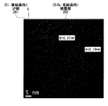
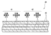
図1は、本技術の一実施形態の二次電池用活物質を用いた電極である負極の断面構成を表しており、図2および図3は、本技術の一実施形態の二次電池用活物質である負極活物質の断面構成を表している。図4〜図7は、負極活物質の断面構造のHAADF STEM写真(以下、単に「TEM写真」という。)である。
<1. Electrode using active material for secondary battery>
FIG. 1 illustrates a cross-sectional configuration of a negative electrode that is an electrode using an active material for a secondary battery according to an embodiment of the present technology. FIGS. 2 and 3 illustrate the secondary battery according to an embodiment of the present technology. The cross-sectional structure of the negative electrode active material which is an active material is represented. 4 to 7 are HAADF STEM photographs (hereinafter, simply referred to as “TEM photographs”) of the cross-sectional structure of the negative electrode active material.
[負極の全体構成]
負極は、例えば、二次電池などに用いられるものであり、図1に示したように、負極集電体1の上に負極活物質層2を有している。この負極活物質層2は、負極集電体1の両面に設けられていてもよいし、片面だけに設けられていてもよい。ただし、負極集電体1はなくてもよい。
[Overall structure of negative electrode]
The negative electrode is used for, for example, a secondary battery, and has a negative electrode
[負極集電体]
負極集電体1は、例えば、電気化学的安定性、電気伝導性および機械的強度に優れた導電性材料により形成されており、その導電性材料は、例えば、Cu、Niまたはステンレスなどの金属材料である。中でも、Liと金属間化合物を形成しないと共に負極活物質層2と合金化する材料が好ましい。
[Negative electrode current collector]
The negative electrode
この負極集電体1は、炭素(C)および硫黄(S)を構成元素として含んでいることが好ましい。負極集電体1の物理的強度が向上するため、充放電時に負極活物質層2が膨張収縮しても負極集電体1が変形しにくくなるからである。具体的には、負極集電体1は、例えば、CおよびSがドープされた金属箔などである。CおよびSの含有量は、特に限定されないが、中でも、100ppm以下であることが好ましい。より高い効果が得られるからである。
The negative electrode
負極集電体1の表面(負極活物質層2と接する面)は、粗面化されていてもよいし、粗面化されていなくてもよい。粗面化されていない負極集電体1は、例えば、圧延金属箔などであると共に、粗面化された負極集電体1は、例えば、電解処理またはサンドブラスト処理などが施された金属箔などである。電解処理とは、電解槽中で電解法を用いて金属箔などの表面に微粒子を形成して凹凸を設ける方法である。電解法により作製された金属箔は、一般的に、電解箔(例えば電解Cu箔など)と呼ばれている。
The surface of the negative electrode current collector 1 (the surface in contact with the negative electrode active material layer 2) may be roughened or may not be roughened. The non-roughened negative electrode
中でも、負極集電体1の表面は、粗面化されていることが好ましい。アンカー効果により、負極集電体1に対する負極活物質層2の密着性が向上するからである。負極集電体1の表面粗さ(例えば十点平均粗さRzなど)は、特に限定されないが、アンカー効果により負極活物質層2の密着性を向上させるために、できるだけ大きいことが好ましい。ただし、表面粗さが大きすぎると、かえって負極活物質層2の密着性が低下する可能性がある。
Especially, it is preferable that the surface of the
[負極活物質層]
負極活物質層2は、電極反応物質(リチウムイオン)を吸蔵放出可能である1または2以上の粒子状の負極活物質を含んでおり、必要に応じて、さらに負極結着剤または負極導電剤などの他の材料を含んでいてもよい。
[Negative electrode active material layer]
The negative electrode
この負極活物質は、SiおよびOを構成元素として含んでおり、必要に応じて他の1種類または2種類以上の元素も含んでいてもよい。ただし、SiおよびOに対するSiの原子割合(Si/(Si+O))は、負極活物質の表面において30原子%〜75原子%である。 This negative electrode active material contains Si and O as constituent elements, and may contain one or more other elements as necessary. However, the atomic ratio of Si to Si and O (Si / (Si + O)) is 30 atomic% to 75 atomic% on the surface of the negative electrode active material.
「表面」とは、厳密には、負極活物質が二次電池に用いられた場合において、電解液と接する負極活物質の最表面(負極活物質と電解液との界面)である。なお、負極活物質の表面に後述する導電層が形成される場合には、「表面」とは、導電層と接する負極活物質の最表面(負極活物質と導電層との界面)である。 Strictly speaking, the “surface” is the outermost surface of the negative electrode active material in contact with the electrolytic solution (interface between the negative electrode active material and the electrolytic solution) when the negative electrode active material is used in a secondary battery. When a conductive layer described later is formed on the surface of the negative electrode active material, the “surface” is the outermost surface of the negative electrode active material in contact with the conductive layer (interface between the negative electrode active material and the conductive layer).
この原子割合は、原子割合(原子%)=[Siの原子量/(Siの原子量+Oの原子量)]×100により算出される。なお、SiおよびOのそれぞれの原子量は、例えば、エネルギー分散型X線分光法(TEM/EDX)を用いて負極活物質の断面を表面側から測定することで特定可能である。TEM装置は日本電子株式会社製のJEM−2100F、EDX装置は日本電子株式会社製のJED−2300Tとする。測定条件は、加速電圧=200kV、ビーム電流=240pA、ビーム径=0.15mm、分析(積算)時間=30秒である。 This atomic ratio is calculated by atomic ratio (atomic%) = [atomic weight of Si / (atomic weight of Si + atomic weight of O)] × 100. In addition, each atomic weight of Si and O can be specified by measuring the cross section of a negative electrode active material from the surface side, for example using energy dispersive X-ray spectroscopy (TEM / EDX). The TEM device is JEM-2100F manufactured by JEOL Ltd., and the EDX device is JED-2300T manufactured by JEOL Ltd. The measurement conditions are acceleration voltage = 200 kV, beam current = 240 pA, beam diameter = 0.15 mm, and analysis (integration) time = 30 seconds.
負極活物質がSiを構成元素として含んでいるのは、高いエネルギー密度が得られるため、高い電池容量が得られるからである。また、負極活物質がSiと共にOと構成元素として含んでいるのは、優れたサイクル特性などが得られるからである。 The reason why the negative electrode active material contains Si as a constituent element is that a high battery density can be obtained because a high energy density is obtained. Moreover, the negative electrode active material contains O and constituent elements together with Si because excellent cycle characteristics and the like can be obtained.
原子割合が負極活物質の表面において30原子%〜75原子%であるのは、優れた初回充放電特性およびサイクル特性が得られるからである。詳細には、原子割合が30原子%よりも小さいと、Oの存在量がSiの存在量に対して相対的に大きくなりすぎるため、電気抵抗が増加する。これにより、初期の充放電時から十分な充放電効率が得られない。一方、原子割合が75原子%よりも大きいと、Siの存在量がOの存在量に対して相対的に大きくなりすぎるため、リチウムイオンの受け入れ性は向上するが、充放電を繰り返すとSiが劣化(表面劣化)しやすくなる。これにより、十分なサイクル特性が得られない。よって、リチウムイオンの受け入れ性を確保しつつ、優れた初回充放電特性およびサイクル特性を得るためには、原子割合が上記範囲内でなければならない。 The reason why the atomic ratio is 30 atomic% to 75 atomic% on the surface of the negative electrode active material is that excellent initial charge / discharge characteristics and cycle characteristics are obtained. Specifically, when the atomic ratio is smaller than 30 atomic%, the amount of O present is too large with respect to the amount of Si, so that the electrical resistance increases. Thereby, sufficient charge / discharge efficiency cannot be obtained from the initial charge / discharge. On the other hand, when the atomic ratio is greater than 75 atomic%, the abundance of Si is too large relative to the abundance of O, so that the acceptability of lithium ions is improved. It becomes easy to deteriorate (surface deterioration). Thereby, sufficient cycle characteristics cannot be obtained. Therefore, in order to obtain excellent initial charge / discharge characteristics and cycle characteristics while ensuring the acceptability of lithium ions, the atomic ratio must be within the above range.
中でも、負極活物質の表面における原子割合は、30原子%〜70原子%であることがより好ましい。より高い効果が得られるからである。 Especially, it is more preferable that the atomic ratio in the surface of a negative electrode active material is 30 atomic%-70 atomic%. This is because a higher effect can be obtained.
この負極活物質のうちの少なくとも表面近傍部分(表面およびその近傍の部分)において、原子割合は、負極活物質の中心に向かってどのように推移していてもよい。すなわち、原子割合は、次第に減少していてもよいし、次第に増加していてもよいし、一定でもよい。 In at least a portion near the surface (a surface and a portion in the vicinity thereof) of the negative electrode active material, the atomic ratio may change in any way toward the center of the negative electrode active material. That is, the atomic ratio may gradually decrease, gradually increase, or may be constant.
中でも、原子割合は、負極活物質の表面から中心に向かって次第に減少していることが好ましい。負極活物質の中心側では、Siの存在量がOの存在量に対して相対的に大きくなるため、リチウムイオンの吸蔵放出量が確保されるからである。これにより、高い電池容量が得られる。また、負極活物質の表面側では、Siの存在量がOの存在量に対して相対的に小さくなるため、負極活物質の表面における原子割合が上記範囲内であれば、リチウムイオンが出入りしやすくなると共に、高いサイクル特性が得られるからである。 Among these, it is preferable that the atomic ratio gradually decreases from the surface of the negative electrode active material toward the center. This is because, on the center side of the negative electrode active material, the abundance of Si is relatively larger than the abundance of O, so that the amount of occlusion and release of lithium ions is secured. Thereby, a high battery capacity is obtained. Further, since the amount of Si present on the surface side of the negative electrode active material is relatively small with respect to the amount of O present, lithium ions can enter and exit if the atomic ratio on the surface of the negative electrode active material is within the above range. It is because it becomes easy and a high cycle characteristic is acquired.
負極活物質のうちの少なくとも表面近傍部分の結晶性は、特に限定されないが、中でも、非結晶性または低結晶性であることが好ましい。充放電に負極活物質が膨張収縮しても、その負極活物質が破損(割れ等)しにくくなるからである。なお、「低結晶性」とは、結晶領域(結晶粒)が非結晶領域の中に点在している結晶状態を意味しており、その詳細に関しては後述する。 The crystallinity of at least the portion in the vicinity of the surface of the negative electrode active material is not particularly limited, but is preferably amorphous or low crystalline. This is because even if the negative electrode active material expands and contracts during charge and discharge, the negative electrode active material is unlikely to break (crack, etc.). Note that “low crystallinity” means a crystal state in which crystal regions (crystal grains) are scattered in an amorphous region, and details thereof will be described later.
上記した負極活物質の表面近傍部分が低結晶性である場合、その低結晶性部分における結晶性の程度は、特に限定されない。中でも、Siの(111)面および(220)面に起因する結晶粒の平均面積占有率は35%以下であると共に、その結晶粒の平均粒径は50nm以下であることが好ましい。より高い効果が得られるからである。なお、平均面積占有率および平均粒径の測定方法に関しては後述する。 When the portion near the surface of the negative electrode active material has low crystallinity, the degree of crystallinity in the low crystallinity portion is not particularly limited. Among them, it is preferable that the average area occupation ratio of crystal grains due to the (111) plane and the (220) plane of Si is 35% or less and the average grain diameter of the crystal grains is 50 nm or less. This is because a higher effect can be obtained. The method for measuring the average area occupancy and the average particle diameter will be described later.
この負極活物質は、上記した物性を有していれば、全体としてはどのような構成を有していてもよい。 The negative electrode active material may have any configuration as a whole as long as it has the above-described physical properties.
例えば、図2(A)に示したように、全体として物理的に1つの粒状体(負極活物質100)でもよい。この負極活物質100のSiに対するOの原子比z(O/Si)は、例えば、0.5≦z≦1.8を満たしている。すなわち、負極活物質100は、Siの酸化物(SiOz :0.5≦z≦1.8)を含んでいる。優れた電池容量、初回充放電特性およびサイクル特性などが得られるからである。
For example, as shown in FIG. 2A, the whole may be physically one granular body (negative electrode active material 100). The atomic ratio z (O / Si) of O to Si of the negative electrode
原子割合は、上記したように、負極活物質100の表面から中心に向かって次第に減少していることが好ましい。負極活物質100の中心側ではSiの存在量がOの存在量に対して相対的に大きくなると共に、表面側ではSiの存在量がOの存在量に対して相対的に小さくなるため、上記した利点が得られるからである。この場合において、負極活物質100の内部の原子割合は、特に限定されないが、中でも、負極活物質100の表面から中心に向かって300nmの位置において、35原子%〜60原子%であることが好ましい。より高い効果が得られるからである。
Atomic ratio, as described above, it is preferable that gradually decreases toward the front surface or et center of the negative electrode
なお、負極活物質100は、SiおよびOと共に、それ以外の元素のいずれか1種類または2種類以上を含んでいてもよい。具体的には、負極活物質100は、Feを構成元素として含んでいることが好ましい。負極活物質100の電気抵抗が低下するからである。この負極活物質100中において、Feは、SiおよびOとは別個に(遊離状態で)存在していてもよいし、SiおよびOのうちの少なくとも一方と合金または化合物を形成していてもよい。このFeを含んでいる負極活物質100の状態(Feの結合状態など)は、例えば、EDXなどを用いて確認可能である。
In addition, the negative electrode
この負極活物質100の結晶性は、特に限定されず、高結晶性でもよいし、低結晶性でもよい。この負極活物質100の低結晶性に関する詳細は、後述する被覆部202の低結晶性と同様であるため、その説明を省略する。
The crystallinity of the negative electrode
または、例えば、図2(B)に示したように、コア部201および被覆部202を含む複合粒状体(負極活物質200)でもよい。この負極活物質200では、コア部201の表面に被覆部202が設けられており、そのようにコア部201が被覆部202により被覆されている様子は、例えば、走査型電子顕微鏡(SEM)などを用いて確認可能である。また、コア部201および被覆部202の結晶性(結晶状態)は、図4〜図6に示したように、TEMなどを用いて確認可能である。
Alternatively, for example, as shown in FIG. 2B, a composite granular material (negative electrode active material 200) including a
原子割合は、上記したように、負極活物質200の表面からコア部201と被覆部202との界面に向かって次第に減少していることが好ましい。負極活物質200の中心側(コア部201)ではSiの存在量がOの存在量に対して相対的に大きくなると共に、表面側(被覆部202)ではSiの存在量がOの存在量に対して相対的に小さくなるため、上記した利点が得られるからである。この場合において、負極活物質200の内部の原子割合は、特に限定されないが、中でも、コア部201と被覆部202との界面において、35原子%〜60原子%であることが好ましい。より高い効果が得られるからである。
As described above, it is preferable that the atomic ratio gradually decreases from the surface of the negative electrode
コア部201は、例えば、SiおよびOを構成元素として含んでおり、そのSiに対するOの原子比x(O/Si)は、0≦x<0.5を満たしている。すなわち、コア部201は、例えば、ケイ素系材料(SiOx :0≦x<0.5)を含んでいる。原子比xが範囲外である場合(x≧0.5)と比較して、充放電時にコア部201がリチウムイオンを吸蔵放出しやすくなると共に不可逆容量が減少するため、高い電池容量が得られるからである。
The
コア部201の形成材料は、上記した組成(原子比x)から明らかなように、Siの単体(x=0)でもよいし、Siの酸化物(SiOx :0<x<0.5)でもよい。ただし、xはできるだけ小さいことが好ましく、x=0(Siの単体)であることがより好ましい。高いエネルギー密度が得られるため、電池容量がより高くなるからである。また、コア部201の劣化が抑制されるため、充放電サイクルの初期から放電容量が低下しにくくなるからである。ただし、「単体」とは、あくまで一般的な意味での単体であり、必ずしも純度100%を意味しているわけではない。すなわち、Siの単体は、微量の不純物(O以外の元素)を含んでいてもよい。
As is apparent from the above composition (atomic ratio x), the material for forming the
コア部201の結晶性は、高結晶性、低結晶性または非結晶性のいずれでもよいが、中でも、高結晶性または低結晶性であることが好ましく、高結晶性であることがより好ましい。充放電時にコア部201がリチウムイオンを吸蔵放出しやすくなるため、高い電池容量などが得られるからである。また、充放電時にコア部201が膨張収縮しにくくなるからである。中でも、X線回折により得られるSiの(111)結晶面に起因する回折ピークの半値幅(2θ)は、20°以下であることが好ましい。また、Siの(111)結晶面に起因する結晶子サイズは、10nm以上であることが好ましい。より高い効果が得られるからである。
The crystallinity of the
なお、コア部201は、SiおよびOと共に、それ以外の元素のいずれか1種類または2種類以上を含んでいてもよい。
In addition, the
具体的には、コア部201は、Feを構成元素として含んでいることが好ましい。コア部201の電気抵抗が低下するからである。SiおよびOに対するFeの割合(Fe/(Si+O))は、特に限定されないが、中でも、0.01重量%〜7.5重量%であることが好ましい。コア部201の電気抵抗が低下するだけでなく、リチウムイオンの拡散性が向上するからである。
Specifically, the
コア部201中において、Feは、SiおよびOとは別個に(遊離状態で)存在していてもよいし、SiおよびOのうちの少なくとも一方と合金または化合物を形成していてもよい。このことは、後述するAl等に関しても同様である。このFeを含んでいるコア部201の状態(Feの結合状態など)は、例えば、EDXなどを用いて確認可能である。
In the
この他、コア部201は、Al、Cr、Ni、B、Mg、Ca、Ti、V、Mn、Co、Cu、Ge、Y、Zr、Mo、Ag、In、Sn、Sb、Ta、W、Pb、La、Ce、PrおよびNdなどのうちの少なくとも1種の元素を構成元素として含んでいてもよい。中でも、Al、Ca、Mn、Cr、MgおよびNiのうちの少なくとも1種が好ましい。コア部201の電気抵抗が低下するからである。SiおよびOに対するAl等の割合(Al等/(Si+O))は、特に限定されない。なお、コア部201がAlを含んでいると低結晶化するため、そのコア部201が充放電時に膨張収縮しにくくなると共に、リチウムイオンの拡散性がより向上する。
In addition, the
コア部201の平均粒径(メジアン径D50)は、特に限定されないが、中でも、0.1μm〜20μmであることが好ましい。より高い効果が得られるからである。詳細には、D50が小さすぎると、表面積が増加するため、安全性の低下を招く可能性があると共に、D50が大きすぎると、充電時の膨張に起因して負極活物質200の破損を招く可能性がある。この他、D50が小さすぎると、負極活物質200を含むスラリーを塗布しにくくなる可能性がある。
Although the average particle diameter (median diameter D50) of the
被覆部202は、コア部201の表面のうちの少なくとも一部に設けられている。このため、被覆部202は、コア部201の表面の一部だけを被覆していてもよいし、全部を被覆していてもよい。前者の場合には、被覆部202がコア部201の表面のうちの複数箇所に点在していてもよい。
The covering
この被覆部202は、例えば、SiおよびOを構成元素として含んでおり、そのSiに対するOの原子比y(O/Si)は、0.5≦y≦1.8を満たしている。すなわち、被覆部202は、例えば、ケイ素系材料(SiOy :0.5≦y≦1.8)を含んでいる。充放電を繰り返しても負極活物質200の劣化が抑制されるからである。これにより、コア部201におけるリチウムイオンの出入りを確保しつつ、被覆部202によりコア部201が化学的および物理的に保護される。
The covering
詳細には、コア部201と電解液との間に被覆部202が介在すると、高反応性のコア部201が電解液と接触しにくくなるため、その電解液の分解反応が抑制される。この場合には、被覆部202がコア部201と同系統の材料(共通の元素(Si)を構成元素として含む材料)により形成されていれば、そのコア部201に対する被覆部202の密着性も高くなる。
Specifically, when the covering
また、被覆部202が柔軟性(変形しやすい性質)を有するため、充放電時にコア部201が膨張収縮しても、それに追随して被覆部202も膨張収縮(伸縮)しやすくなる。これにより、コア部201の膨張収縮時に被覆部202が破損(断裂等)しにくくなるため、被覆部202によるコア部201の被覆状態が充放電を繰り返しても維持される。よって、充放電時にコア部201が割れても新生面が露出しにくくなると共に、その新生面が電解液と接触しにくくなるため、電解液の分解反応が著しく抑制される。
In addition, since the covering
被覆部202の形成材料は、上記した組成(原子比y)から明らかなように、Siの酸化物(SiOy )である。中でも、原子比yは、0.7≦y≦1.3を満たしていることが好ましく、y=1.2であることがより好ましい。より高い効果が得られるからである。なお、被覆部202は、SiおよびOと共に、それ以外の元素のいずれか1種類または2種類以上を含んでいてもよい。具体的には、被覆部202は、Fe、AlおよびCaのうちの少なくとも1種類を構成元素として含んでいることが好ましい。被覆部202の電気抵抗が低下するからである。SiおよびOに対するFe等の割合(Fe等/(Si+O))は、任意である。
As is apparent from the composition (atomic ratio y), the material for forming the covering
被覆部202の結晶性は、特に限定されないが、コア部201の結晶性よりも低い(非結晶性に近い)ことが好ましく、より具体的には低結晶性または非結晶性(非晶質)であることが好ましい。高結晶性である場合と比較して、リチウムイオンが拡散されやすいため、コア部201の表面が被覆部202により被覆されていても、そのコア部201がリチウムイオンを円滑に吸蔵放出しやすくなるからである。なお、「被覆部202の結晶性がコア部201の結晶性よりも低い」とは、例えば、コア部201が高結晶性である場合には、被覆部202が低結晶性または非結晶性であることを意味している。または、例えば、コア部201が低結晶性である場合には、被覆部202が非結晶性であることを意味している。
The crystallinity of the covering
中でも、被覆部202は、非結晶性であることがより好ましい。被覆部202の柔軟性が向上するため、その被覆部202が充放電時にコア部201の膨張収縮に追随しやすくなるからである。また、被覆部202がリチウムイオンをトラップしにくくなるため、コア部201におけるリチウムイオンの出入りがより阻害されにくくなるからである。
Among these, the covering
なお、図4および図7では、コア部201が高結晶性のSiであると共に被覆部202が非結晶性のSiOy である場合を示している。一方、図5および図6では、コア部201が高結晶性のSiであると共に被覆部202が低結晶性のSiOy である場合を示している。
4 and 7 show a case where the
ここで、「低結晶性」とは、HAADF STEMなどを用いて被覆部202の断面あるいは表面を観察した場合に、非結晶領域および結晶領域(結晶粒)の双方が存在している結晶状態を意味している。TEM写真から非結晶領域と結晶領域とが混在している様子を確認できれば、その被覆部202は低結晶性である。なお、非結晶領域と結晶領域とが混在している場合、その結晶領域は、粒状の輪郭を有する領域(結晶粒)として観察される。この結晶粒の内部には、結晶性に起因する縞状の模様(結晶格子縞)が観察されるため、その結晶粒を非結晶領域から識別できる。これに対して、「非結晶性」とは、いわゆる非晶質と同義であり、HAADF STEMなどを用いて被覆部を観察した場合に、非結晶領域だけが存在しており、結晶領域が存在していない結晶状態を意味している。なお、観察時の倍率は、例えば、1.2×10⁶ 倍とする。
Here, “low crystallinity” means a crystalline state in which both a non-crystalline region and a crystalline region (crystal grain) exist when a cross section or surface of the covering
非結晶性と低結晶性との違いは、図4および図5に示したTEM写真から明らかである。被覆部202が非結晶性である場合には、図4に示したように、非結晶領域だけが観察され、結晶領域(結晶格子縞を有する結晶粒)が観察されない。これに対して、被覆部202が低結晶性である場合には、図5に示したように、非結晶領域の中に結晶粒(矢印で指した部分)が点在している様子が観察される。この結晶粒は、Siの格子面間隔dに応じた所定の間隔の結晶格子縞を有しているため、その周辺の非結晶領域から明確に区別される。なお、図5に示したTEM写真をフーリエ変換した(電子回折図に相当する図を得た)ところ、スポットがリング状に並んでいたため、被覆部202の内部に多数の結晶領域が存在していることが確認された。
The difference between non-crystalline and low crystalline is evident from the TEM photographs shown in FIGS. When the covering
なお、HAADF STEMによる外郭部の観察手順は、例えば、以下の通りである。最初に、Cu製のTEM用グリッドの表面に接着剤を塗布したのち、その接着剤の上にサンプル(負極活物質200)をふりかける。続いて、真空蒸着法を用いて粉体サンプルの表面に炭素材料(黒鉛)を堆積させる。続いて、集束イオンビーム(FIB)法を用いて炭素材料の表面に薄膜(Pt/W)を堆積させたのち、さらに薄膜加工(加速電圧=30kV)する。最後に、HAADF STEM(加速電圧=200kV)を用いて負極活物質200の断面を観察する。この観察方法は、サンプルの組成に敏感な手法であり、一般に、原子番号のほぼ2乗に比例した明るいコントラストの画像が得られる。
In addition, the observation procedure of the outline part by HAADF STEM is as follows, for example. First, an adhesive is applied to the surface of a Cu TEM grid, and then a sample (negative electrode active material 200) is sprinkled on the adhesive. Subsequently, a carbon material (graphite) is deposited on the surface of the powder sample using a vacuum evaporation method. Subsequently, after a thin film (Pt / W) is deposited on the surface of the carbon material using a focused ion beam (FIB) method, the thin film is further processed (acceleration voltage = 30 kV). Finally, the cross section of the negative electrode
図4および図5に示したTEM写真では、線Lを境界として結晶状態の異なる領域が観察される。この結晶状態の異なる領域をEDXで分析したところ、線Lよりも内側に位置する領域は高結晶性のコア部201(Si)であると共に、線Lよりも外側に位置する領域は低結晶性または非結晶性の被覆部202(SiOy )であることが確認された。 In the TEM photographs shown in FIGS. 4 and 5, regions having different crystal states with the line L as a boundary are observed. When the regions having different crystal states are analyzed by EDX, the region located inside the line L is a highly crystalline core portion 201 (Si) and the region located outside the line L is low crystalline. Or it was confirmed that it was the non-crystalline covering portion 202 (SiO y ).
被覆部202の低結晶性の程度は、特に限定されないが、中でも、Siの(111)面および(220)面に起因する結晶粒の平均面積占有率は、35%以下であることが好ましく、25%以下、さらに20%以下であることがより好ましい。より高い効果が得られるからである。図5に示したように、「(111)面に起因する結晶粒」とは、格子面間隔d=0.31nmの結晶格子縞を有する結晶領域であり、「(220)面に起因する結晶粒」とは、格子面間隔d=0.19nmの結晶格子縞を有する結晶領域である。
The degree of low crystallinity of the covering
この平均面積占有率の算出手順は、以下の通りである。最初に、図6に示したように、HAADF STEMを用いて被覆部202の断面を観察してTEM写真を得る。この場合には、観察倍率=1.2×10⁶ 倍、観察エリア=65.6nm×65.7nmとする。なお、図6は、図5と同じ領域を観察したTEM写真である。続いて、結晶格子縞の有無および格子面間隔dの値などを調べて、Siの(111)面に起因する結晶粒および(220)面に起因する結晶粒が存在する範囲を特定したのち、それらの結晶粒の輪郭をTEM写真中に描画する。続いて、各結晶粒の面積を算出したのち、面積占有率(%)=(結晶粒の面積の和/観察エリアの面積)×100を算出する。これらの輪郭の描画および面積占有率の算出に関しては、人為的に行ってもよいし、専用の処理ソフトなどを用いて機械的に行ってもよい。最後に、面積占有率の算出作業を40エリアで繰り返したのち、各エリアで算出した面積占有率の平均値(平均面積占有率)を算出する。この場合には、結晶粒の分布傾向を加味して平均面積占有率を算出するために、被覆部202を厚さ方向に二等分して、その内側部分および外側部分で20エリアずつ面積占有率を算出することが好ましい。
The procedure for calculating the average area occupancy is as follows. First, as shown in FIG. 6, a cross-section of the covering
上記したように被覆部202を厚さ方向に二等分したとき、平均面積占有率は、内側部分と外側部分とで同じでもよいし、異なってもよい。中でも、内側部分における結晶粒の平均面積占有率は、外側部分における結晶粒の平均面積占有率と同じであるか、それよりも大きいことが好ましい(内側部分の平均面積占有率≧外側部分の平均面積占有率)。より高い効果が得られるからである。このことは、平均粒径に関しても同様である。なお、内側部分および外側部分における平均面積占有率および平均粒径は、上記したように、それぞれ20エリアずつ算出されることとする。
As described above, when the covering
また、上記した結晶粒の平均粒径は、特に限定されないが、中でも、55nm以下であることが好ましく、50nm以下であることがより好ましい。より高い効果が得られるからである。この平均粒径の算出手順は、エリアごとに平均粒径を算出したのち、その平均粒径の平均値(最終的な平均粒径)を算出することを除き、平均面積占有率を算出した場合と同様である。なお、結晶粒の粒径を測定する場合には、例えば、結晶粒の輪郭を円に変換(結晶粒の輪郭により画定される形状と同等の面積を有する円を特定)したのち、その円の直径を粒径とする。この粒径の算出は、平均面積占有率を算出した場合と同様に、人為的でも機械的でもよい。 The average grain size of the crystal grains is not particularly limited, but is preferably 55 nm or less, and more preferably 50 nm or less. This is because a higher effect can be obtained. This average particle size calculation procedure is to calculate the average area occupancy rate except for calculating the average particle size for each area and then calculating the average value of the average particle size (final average particle size) It is the same. When measuring the grain size of a crystal grain, for example, after converting the outline of the crystal grain into a circle (specifying a circle having an area equivalent to the shape defined by the outline of the crystal grain), Let the diameter be the particle size. The calculation of the particle size may be artificial or mechanical as in the case of calculating the average area occupancy.
この被覆部202の平均厚さは、特に限定されないが、中でも、できるだけ薄いことが好ましく、1nm〜3000nmであることがより好ましい。コア部201がリチウムイオンを吸蔵放出しやすくなると共に、被覆部202による保護機能が効果的に発揮されるからである。詳細には、平均厚さが1nmよりも小さいと、被覆部202がコア部201を保護しにくくなる可能性がある。一方、平均厚さが3000nmよりも大きいと、電気抵抗が高くなると共に、充放電時にコア部201がリチウムイオンイオンを吸蔵放出しにくくなる可能性がある。被覆部202の形成材料がSiOy である場合、そのSiOy はリチウムイオンを吸蔵しやすい一方で、一旦吸蔵したリチウムイオンを放出しにくい性質を有するからである。
Although the average thickness of this coating |
被覆部202の平均厚さは、以下の手順により算出される。まず、SEMなどを用いて1個の負極活物質200を観察する。この観察時の倍率は、被覆部202の厚さを測定するために、コア部201と被覆部202との境界を目視で確認(決定)できるような倍率であることが好ましい。続いて、任意の10点で被覆部202の厚さを測定したのち、その平均値(1個当たりの平均厚さT)を算出する。この場合には、できるだけ特定の場所周辺に集中せずに広く分散されるように測定位置を設定することが好ましい。続いて、SEMによる観察個数の総数が100個になるまで、上記した平均値の算出作業を繰り返す。最後に、100個の負極活物質200に関して算出された平均値(1個当たりの平均厚さT)の平均値(平均厚さTの平均値)を算出して、被覆部202の平均厚さとする。
The average thickness of the covering
また、コア部201に対する被覆部202の平均被覆率は、特に限定されないが、できるだけ大きいことが好ましく、中でも、30%以上(30%〜100%)であることがより好ましい。被覆部202の保護機能がより向上するからである。
The average coverage of the covering
被覆部202の平均被覆率は、以下の手順により算出される。まず、平均厚さを算出した場合と同様に、SEMなどを用いて1個の負極活物質200を観察する。この観察時の倍率は、コア部201のうち、被覆部202により被覆されている部分と被覆されていない部分とを目視で識別できるような倍率であることが好ましい。続いて、コア部201の外縁(輪郭)のうち、被覆部202により被覆されている部分の長さと被覆されていない部分の長さとを測定する。そして、被覆率(1個当たりの被覆率:%)=(被覆部202により被覆されている部分の長さ/コア部201の外縁の長さ)×100を算出する。続いて、SEMによる観察個数の総数が100個になるまで、上記した被覆率の算出作業を繰り返す。最後に、100個の負極活物質200に関して算出された被覆率(1個当たりの被覆率)の平均値を算出して、被覆部202の平均被覆率とする。
The average coverage of the covering
なお、被覆部202はコア部201に隣接していることが好ましいが、コア部201と被覆部202との間に自然酸化膜(SiO2 )が介在していてもよい。この自然酸化膜は、例えば、コア部201の表層近傍が大気中で酸化されたものである。負極活物質200の中心にコア部201が存在すると共に外側に被覆部202が存在すれば、自然酸化膜の存在はコア部201および被覆部202の機能にほとんど影響を及ぼさない。
The covering
ここで、負極活物質200がコア部201および被覆部202を含んでいることを確認するためには、上記したSEM観察の他、例えば、X線光電子分光法(XPS)またはエネルギー分散型X線分析法(EDX)などを用いて負極活物質200を分析してもよい。
Here, in order to confirm that the negative electrode
この場合には、負極活物質200の中心部および表層部の酸化度(原子x,y)などを測定すれば、コア部201および被覆部202の組成を確認できる。なお、被覆部202により被覆されているコア部201の組成を調べるためには、HFなどの酸を用いて被覆部202を溶解除去すればよい。
In this case, the composition of the
酸化度の測定に関する詳細な手順は、例えば、下記の通りである。最初に、燃焼法を用いて負極活物質200を定量して、全体のSi量およびO量を算出する。続いて、HFなどを用いて被覆部202を洗浄除去したのち、燃焼法を用いてコア部201を定量してSi量およびO量を算出する。最後に、全体のSi量およびO量からコア部201のSi量およびO量を差し引いて、被覆部202のSi量およびO量を算出する。これにより、コア部201のSi量およびO量が特定されるため、そのコア部201の酸化度を特定できる。同様に、被覆部202の酸化度も特定できる。なお、被覆部202を洗浄除去する代わりに、被覆部202により被覆されたコア部201と共に未被覆のコア部201を用いて酸化度を測定してもよい。
A detailed procedure for measuring the degree of oxidation is, for example, as follows. First, the negative electrode
なお、負極活物質層2中において、複数の負極活物質200は互いに離間(分散)されていてもよいし、そのうちの2つ以上が接触(または連結)されていてもよい。2つ以上の負極活物質200が接触する場合、その負極活物質200同士の位置関係は任意でよい。
In the negative electrode
なお、被覆部202は、その内部に1または2以上の空隙を有しており、その空隙のうちの少なくとも一部に導電性材料が設けられていることが好ましい。すなわち、導電性材料は空隙に挿入されており、その空隙は導電性材料により埋められていることが好ましい。上記したコア部201の膨張収縮に追随する被覆部202の膨張収縮性を阻害せずに、負極活物質200の導電性が向上すると共に電解液の分解反応が抑制されるからである。この導電性材料は、例えば、炭素(C)を構成元素として含んでいることが好ましく、その導電性材料の具体例は、「他の負極活物質」として後述する炭素材料などである。
In addition, it is preferable that the coating |
詳細には、被覆部202の内部に存在する空隙は、充放電時に負極活物質200が膨張収縮した際に生じる内部応力を緩和するためのスペースとして利用される。このため、被覆部202が空隙を有していると、負極活物質200が充放電時に破損しにくくなる。その一方で、空隙は、その内部に高反応性の被覆部202を露出させることになるため、その露出面で電解液が分解しやすくなる。この点に関して、空隙に導電性材料が設けられていると、その空隙の内部に高反応性の被覆部202が露出しにくくなるため、電解液の分解反応が抑制される。しかも、炭素は変形性(柔軟性)および高導電性に優れているため、炭素を構成元素として含む導電性材料はコア部201の膨張収縮に追随する被覆部202の膨張収縮性を阻害しにくいと共に、その被覆部202の導電性が向上する。
Specifically, the voids present inside the covering
なお、導電性材料は、Cだけを構成元素として含んでいてもよいし、そのCと共にそれ以外の元素のいずれか1種類または2種類以上を含んでいてもよい。この「他の元素」の種類は、特に限定されないが、例えば、水素(H)または酸素(O)などである。 Note that the conductive material may contain only C as a constituent element, or may contain any one kind or two or more kinds of other elements together with the C. The type of the “other element” is not particularly limited, and is, for example, hydrogen (H) or oxygen (O).
上記した空隙の形成要因は、特に限定されない。いかなる要因で形成されたかを問わず、被覆部202中に空隙が存在していれば、その空隙は応力緩和用のスペースとして機能し得るからである。
The formation factor of an above-mentioned space | gap is not specifically limited. This is because, if a void exists in the covering
この被覆部202は、単層でもよいし、多層でもよいが、中でも、図7に示したように、多層であることが好ましい。被覆部202中(層間)に応力緩和用のスペース(空隙)が形成されやすいからである。図7に示した破線は、各層の境界の目安を表している。ただし、被覆部202は、全体に渡って多層でもよいし、一部だけ多層でもよい。
The covering
なお、例えば、図3に示したように、負極活物質100,200の表面に導電層210が設けられていることが好ましい。高反応性の負極活物質100,200が電解液と接触しにくくなるため、その電解液の分解反応が抑制されるからである。また、負極活物質100,200の電気抵抗が低下するからである。
For example, as illustrated in FIG. 3, it is preferable that a
導電層210は、負極活物質100,200の表面の一部だけを被覆していてもよいし、全部を被覆していてもよい。前者の場合には、導電層210が負極活物質100,200の表面の複数箇所に点在していてもよい。
The
この導電層210は、例えば、負極活物質100,200よりも低い電気抵抗を有していることが好ましく、より具体的には、Cを構成元素として含んでいることが好ましい。より高い効果が得られるからである。なお、導電層210の形成材料が導電性材料の形成材料と同じである場合には、その導電性材料の代わりに導電層210の一部により被覆部202の空隙が埋められており、その空隙が封孔されていてもよい。導電性材料と導電層210とを実質的に一括して形成できるからである。
For example, the
ここで、一般的に、ラマンスペクトル法を用いて炭素材料を測定すると、そのラマンスペクトルには、黒鉛構造に由来するGバンドピークが1590cm-1近傍に検出されると共に、欠陥に由来するDバンドピークが1350cm-1近傍に検出される。このGバンドピークの強度IGとDバンドピークの強度IDとの比IG/IDは、G/D比とも呼ばれており、炭素材料の結晶性(純度)を表す指標である。 Here, generally, when a carbon material is measured using the Raman spectrum method, a G band peak derived from a graphite structure is detected in the vicinity of 1590 cm −1 in the Raman spectrum, and a D band derived from a defect. A peak is detected in the vicinity of 1350 cm −1 . The ratio IG / ID between the intensity IG of the G band peak and the intensity ID of the D band peak is also called a G / D ratio, and is an index representing the crystallinity (purity) of the carbon material.
Cを構成元素として含む導電層210の比IG/IDは、特に限定されないが、中でも、0.3〜3.2であることが好ましく、2近辺であることがより好ましい。優れた結着性、導電性および変形性が得られるからである。
The ratio IG / ID of the
詳細には、比IG/IDが0.3よりも小さいと、結着性が高くなるため、導電層210同士の密着性および負極活物質100,200に対する導電層の密着性が向上する。しかしながら、導電性が低下すると共に硬くなるため、負極活物質100,200の膨張収縮に追随して導電層210が膨張収縮しにくくなると共に十分な導電性が得られない可能性がある。一方、比IG/IDが3.2よりも大きいと、導電性が高くなると共に軟らかくなるため、負極活物質100,200の膨張収縮に追随して導電層210が膨張収縮しやすくなると共に十分な導電性が得られる。しかしながら、結着性が低下するため、導電層210同士の密着性および負極活物質100,200に対する導電層210の密着性が低下する可能性がある。これに対して、比IG/IDが0.3〜3であると、導電層210の結着性および導電性が高くなると共に、負極活物質100,200の膨張収縮に追随して導電層210が膨張収縮しやすくなる。
Specifically, when the ratio IG / ID is smaller than 0.3, the binding property is increased, so that the adhesion between the
なお、導電層210は、Cと共にそれ以外の元素のいずれか1種類または2種類以上を含んでいてもよい。この「他の元素」の種類は、特に限定されないが、例えば、HまたはOなどである。この導電層210の形成材料の具体例は、「他の負極活物質」として後述する炭素材料などである。
Note that the
導電層210の平均厚さは、特に限定されないが、中でも、200nm以下であることが好ましい。また、負極活物質100,200に対する導電層210の平均被覆率は、特に限定されないが、中でも、30%以上であることが好ましい。より高い効果が得られるからである。特に、平均厚さが200nmよりも大きいと、負極活物質100,200を含むスラリーの性状が悪化するため、そのスラリーを塗布しにくくなる可能性がある。なお、導電層210の平均被覆率および平均厚さの算出手順に関する詳細は、上記した被覆部202と同様である。
The average thickness of the
負極結着剤は、例えば、合成ゴムまたは高分子材料などのいずれか1種類または2種類以上を含んでいる。合成ゴムは、例えば、スチレンブタジエン系ゴム、フッ素系ゴムまたはエチレンプロピレンジエンなどである。高分子材料は、例えば、ポリフッ化ビニリデン、ポリイミド、ポリアミド、ポリアミドイミド、ポリアクリル酸、ポリアクリル酸リチウム、ポリアクリル酸ナトリウム、ポリマレイン酸またはこれらの共重合体などである。この他、高分子材料は、例えば、カルボキシメチルセルロース、スチレンブタジエンゴムまたはポリビニルアルコールなどでもよい。 The negative electrode binder contains, for example, any one kind or two or more kinds such as synthetic rubber or polymer material. Examples of the synthetic rubber include styrene butadiene rubber, fluorine rubber, and ethylene propylene diene. Examples of the polymer material include polyvinylidene fluoride, polyimide, polyamide, polyamideimide, polyacrylic acid, lithium polyacrylate, sodium polyacrylate, polymaleic acid, and copolymers thereof. In addition, the polymer material may be, for example, carboxymethyl cellulose, styrene butadiene rubber, or polyvinyl alcohol.
負極導電剤は、例えば、黒鉛、カーボンブラック、アセチレンブラックまたはケチェンブラックなどの炭素材料のいずれか1種類または2種類以上を含んでいる。なお、負極導電剤は、導電性を有する材料であれば、金属材料または導電性高分子などでもよい。 The negative electrode conductive agent contains any one or more of carbon materials such as graphite, carbon black, acetylene black, and ketjen black. The negative electrode conductive agent may be a metal material or a conductive polymer as long as it is a conductive material.
なお、負極活物質層2は、必要に応じて、上記した負極活物質と共に、他の種類の負極活物質のいずれか1種類または2種類以上を含んでいてもよい。
In addition, the negative electrode
この「他の負極活物質」は、例えば、炭素材料である。負極活物質層2の電気抵抗が低下すると共に、その負極活物質層2が充放電時に膨張収縮しにくくなるからである。この炭素材料は、例えば、易黒鉛化性炭素、(002)面の面間隔が0.37nm以上の難黒鉛化性炭素、または(002)面の面間隔が0.34nm以下の黒鉛などである。より具体的には、熱分解炭素類、コークス類、ガラス状炭素繊維、有機高分子化合物焼成体、活性炭またはカーボンブラック類などがある。このうち、コークス類には、ピッチコークス、ニードルコークスまたは石油コークスなどが含まれる。有機高分子化合物焼成体とは、フェノール樹脂やフラン樹脂などを適当な温度で焼成して炭素化したものである。炭素材料の形状は、繊維状、球状、粒状または鱗片状のいずれでもよい。
This “other negative electrode active material” is, for example, a carbon material. This is because the electrical resistance of the negative electrode
また、他の負極活物質は、金属酸化物または高分子化合物でもよい。金属酸化物は、例えば、酸化鉄、酸化ルテニウムまたは酸化モリブデンなどである。高分子化合物は、例えば、ポリアセチレン、ポリアニリンまたはポリピロールなどである。 The other negative electrode active material may be a metal oxide or a polymer compound. Examples of the metal oxide include iron oxide, ruthenium oxide, and molybdenum oxide. Examples of the polymer compound include polyacetylene, polyaniline, and polypyrrole.
負極活物質層2は、例えば、塗布法、焼成法(焼結法)またはそれらの2種類以上の方法により形成されている。塗布法とは、例えば、負極活物質を負極結着剤などと混合したのち、有機溶剤などに分散させて塗布する方法である。焼成法とは、例えば、塗布法と同様の手順により塗布したのち、負極結着剤などの融点よりも高い温度で熱処理する方法である。焼成法としては、公知の手法を用いることができる。例えば、雰囲気焼成法、反応焼成法またはホットプレス焼成法などである。
The negative electrode
[負極の製造方法]
この負極は、例えば、以下の手順により製造される。なお、負極集電体1および負極活物質層2の形成材料に関しては既に詳細に説明したので、その説明を省略する。
[Production method of negative electrode]
This negative electrode is manufactured, for example, by the following procedure. In addition, since the formation material of the
負極活物質100を用いる場合には、最初に、例えば、ガスアトマイズ法、水アトマイズ法または溶融粉砕法などを用いて、粒子状(粉末状)のSi酸化物(SiOz :0.5≦z≦1.8)を得る。この場合には、原材料と一緒に金属材料を溶融させて、Si酸化物にFeなどの金属元素を含有させてもよい。続いて、Si酸化物を高温(例えば1000℃以下)で加熱する。これにより、Si酸化物の表面が還元処理され、その表面における原子割合が変化するため、負極活物質100が得られる。この場合には、必要に応じて、H2 ガスなどを用いてもよい。この負極活物質100の表面における原子割合は、例えば、圧力、加熱温度およびH2 ガスの導入量などの条件に応じて制御される。
When the negative electrode
負極活物質200を用いる場合には、最初に、例えば、ガスアトマイズ法、水アトマイズ法または溶融粉砕法などを用いて、粒子状(粉末状)のコア部201(SiOx :0≦x<0.5)を得る。なお、コア部201にFeなどの金属元素を含有させる場合には、原材料と一緒に金属材料を溶融させる。
When the negative electrode
続いて、例えば、蒸着法またはスパッタ法などの気相成長法を用いて、コア部201の表面に被覆部202(SiOy :0.5≦y≦1.8)を形成する。このように気相成長法を用いると、被覆部202が非結晶性になりやすい傾向がある。この場合には、加熱しながら堆積処理を行い、または被覆部202の形成後に加熱することで、その被覆部202を低結晶性にしてもよい。低結晶性の程度は、例えば、加熱時の温度および時間などの条件に応じて制御される。この加熱処理により、被覆部202中の水分が除去されると共に、コア部201に対する被覆部202の密着性が向上する。
Subsequently, the covering portion 202 (SiO y : 0.5 ≦ y ≦ 1.8) is formed on the surface of the
続いて、負極活物質100を得る場合と同様の手順により、被覆部202を高温(例えば1000℃以下)で加熱(還元)して、その被覆部202の表面における原子割合を変化させることで、負極活物質200を得る。この被覆部202の表面における原子割合は、例えば、圧力、温度およびH2 ガスの導入量などの条件に応じて制御される。
Subsequently, the covering
被覆部202を形成する場合には、必要に応じて、コア部201を回転させながら、シャッタなどの開閉機構を用いて堆積処理の可否を制御することで、多方向から複数回に渡ってコア部201の表面に堆積処理を施すことが好ましい。コア部201の表面が被覆部202により均一に覆われやすいからである。また、被覆部202が多層になるため、層間に応力緩和用のスペース(空隙)が形成されやすくなるからである。
In the case of forming the covering
被覆部202が空隙を有する場合には、熱分解化学蒸着(CVD)法などを用いて導電性材料を堆積させて、その被覆部202の空隙に導電性材料を埋め込むことが好ましい。この熱分解CVD法を用いる場合には、炭素源(有機ガス)として、例えば、メタン、エタン、エチレン、アセチレンまたはプロパンなどを用いる。熱分解CVD法を用いることで、微細な空隙の内部まで炭素源が到達して熱分解されるため、その微細な空隙を導電性材料で容易に埋めることができる。このように被覆部202の微細な空隙に導電性材料が埋め込まれる構造は、上記したように、熱分解CVD法などを用いて導電性材料を被覆部202とは別個に形成することで初めて実現される特徴的な構造である。
In the case where the covering
負極活物質100,200を得たのち、必要に応じて、気相成長法または湿式コート法などを用いて負極活物質100,200の表面に導電層210を形成してもよい。この気相成長法は、例えば、蒸着法、スパッタ法、熱分解CVD法、電子ビーム蒸着法または糖炭化法などである。中でも、熱分解CVD法が好ましい。導電層210が均一な厚さとなるように形成されやすいからである。
After obtaining the negative electrode
蒸着法を用いる場合には、例えば、負極活物質100,200の表面に蒸気を直接吹き付けて導電層210を形成する。スパッタ法を用いる場合には、例えば、Arガスを導入しながら粉体スパッタ法を用いて導電層210を形成する。CVD法を用いる場合には、例えば、金属塩化物を昇華させたガスとH2 およびN2 などの混合ガスとを、金属塩化物のモル比が0.03〜0.3となるように混合したのち、加熱(1000℃以上)して導電層210を形成する。湿式コート法を用いる場合には、例えば、負極活物質100,200を含むスラリーに含金属溶液を添加しながらアルカリ溶液を添加して金属水酸化物を形成する。こののち、水素による還元処理(450℃)を行って負極活物質100,200の表面に導電層210を形成する。なお、導電層210の形成材料として炭素材料を用いる場合には、負極活物質100,200をチャンバ内に投入し、そのチャンバ内に有機ガスを導入したのち、加熱処理(10000Pa、1000℃以上×5時間)を行って導電層210を形成する。この有機ガスの種類は、加熱分解により炭素を生じさせるものであれば特に限定されないが、例えば、メタン、エタン、エチレン、アセチレンまたはプロパンなどである。
When the vapor deposition method is used, for example, the
なお、導電層210を形成する場合には、その形成工程で表面の還元処理と導電層210の形成処理とを行ってもよい。この場合には、必要に応じて、過酸化水素と濃硫酸との酸化反応により表面をSiO2 化して還元作用を意図的に低減させることで、その還元量を制御してもよい。
Note that when the
続いて、負極活物質と負極結着剤などの他の材料とを混合して負極合剤としたのち、有機溶剤などの溶媒に溶解させて負極合剤スラリーとする。最後に、負極集電体1の表面に負極合剤スラリーを塗布してから乾燥させて負極活物質層2を形成する。こののち、必要に応じて負極活物質層2を圧縮成型および加熱(焼成)してもよい。
Subsequently, the negative electrode active material and another material such as a negative electrode binder are mixed to form a negative electrode mixture, and then dissolved in a solvent such as an organic solvent to obtain a negative electrode mixture slurry. Finally, the negative electrode mixture slurry is applied to the surface of the negative electrode
[負極の作用および効果]
この負極によれば、負極活物質がSiおよびOを構成元素として含んでおり、SiおよびOに対するSiの原子割合が負極活物質の表面において30原子%〜75原子%である。これにより、上記したように、負極活物質の表面における原子割合が適正化されるため、リチウムイオンの円滑な吸蔵放出が維持されたまま、抵抗増加が抑制されると共に、充放電を繰り返した場合におけるSiの表面劣化も抑制される。よって、負極を用いた二次電池の性能向上に寄与できる。
[Operation and effect of negative electrode]
According to this negative electrode, the negative electrode active material contains Si and O as constituent elements, and the atomic ratio of Si to Si and O is 30 atomic% to 75 atomic% on the surface of the negative electrode active material. Thereby, as described above, the atomic ratio on the surface of the negative electrode active material is optimized, so that the increase in resistance is suppressed while the smooth occlusion / release of lithium ions is maintained, and charging / discharging is repeated. The surface deterioration of Si is also suppressed. Therefore, it can contribute to the performance improvement of the secondary battery using a negative electrode.
特に、負極活物質のうちの少なくとも表面近傍部分において原子割合が負極活物質の表面から中心に向かって減少しており、または一定であれば、より高い効果を得ることができる。また、負極活物質のうちの少なくとも表面近傍部分が非結晶性または低結晶性であり、結晶粒の平均面積占有率が35%以下であると共に平均粒径が50nm以下であれば、より高い効果を得ることができる。 In particular, if the atomic ratio decreases from the surface of the negative electrode active material toward the center at least in the vicinity of the surface of the negative electrode active material or is constant, a higher effect can be obtained. In addition, if at least the vicinity of the surface of the negative electrode active material is non-crystalline or low crystalline, the average area occupancy of the crystal grains is 35% or less, and the average grain size is 50 nm or less, the higher effect is obtained. Can be obtained.
また、負極活物質の原子比zが0.5≦z≦1.8を満たす場合には、原子割合が負極活物質の中心に向かって次第に減少しており、その負極活物質の表面から中心に向かって300nmの位置における原子割合が35原子%〜60原子%であれば、より高い効果を得ることができる。 Further, when the atomic ratio z of the negative electrode active material satisfies 0.5 ≦ z ≦ 1.8, the atomic ratio gradually decreases toward the center of the negative electrode active material, and the center from the surface of the negative electrode active material If the atomic ratio at the position of 300 nm toward 35 is 35 atomic% to 60 atomic%, a higher effect can be obtained.
また、負極活物質がコア部201(原子比xは0≦x<0.5)および被覆部202(原子比yは0.5≦y≦1.8)を含む場合には、原子割合が負極活物質の表面からコア部201と被覆部202との界面に向かって次第に減少しており、その界面における原子割合が30原子%〜60原子%であれば、より高い効果を得ることができる。この場合には、コア部201のメジアン径(D50)や、被覆部202の平均厚さまたは平均被覆率や、被覆部202を厚さ方向において二等分したときの内側部分と外側部分とにおける平均面積占有率および平均粒径の大小関係や、被覆部202における結晶粒の平均面積占有率または平均粒径が適正範囲内であれば、より高い効果を得ることができる。
When the negative electrode active material includes the core portion 201 (atomic ratio x is 0 ≦ x <0.5) and the covering portion 202 (atomic ratio y is 0.5 ≦ y ≦ 1.8), the atomic ratio is When the atomic ratio at the interface gradually decreases from the surface of the negative electrode active material toward the interface between the
また、被覆部202が空隙を有し、その空隙に導電性材料が設けられていれば、より高い効果を得ることができる。
Further, if the covering
また、負極活物質の表面に導電層210が設けられていれば、より高い効果を得ることができる。この場合には、導電層210がCを構成元素として含み、その導電層210の比IG/IDが0.3〜3.2であれば、さらに高い効果を得ることができる。また、導電層210の平均厚さまたは平均被覆率が適正範囲内であれば、より高い効果を得ることができる。
Further, if the
<2.二次電池>
次に、上記した二次電池用負極を用いた二次電池について説明する。
<2. Secondary battery>
Next, a secondary battery using the above-described negative electrode for a secondary battery will be described.
<2−1.角型>
図8および図9は、角型の二次電池の断面構成を表しており、図9では、図8に示したIX−IX線に沿った断面を示している。また、図10は、図9に示した正極21および負極22の平面構成を模式的に表している。
<2-1. Square type>
8 and 9 illustrate a cross-sectional configuration of the square secondary battery, and FIG. 9 illustrates a cross-section along the line IX-IX illustrated in FIG. 8. FIG. 10 schematically shows a planar configuration of the positive electrode 21 and the
[二次電池の全体構成]
角型の二次電池は、主に、電池缶11の内部に電池素子20が収納されたものである。この電池素子20は、セパレータ23を介して正極21と負極22とが積層および巻回された巻回積層体であり、電池缶11の形状に応じて扁平状になっている。
[Overall structure of secondary battery]
The rectangular secondary battery is mainly one in which the battery element 20 is housed inside the battery can 11. The battery element 20 is a wound laminate in which a positive electrode 21 and a
電池缶11は、例えば、角型の外装部材である。この角型の外装部材は、図9に示したように、長手方向における断面が矩形型または略矩形型(一部に曲線を含む)の形状を有しており、矩形状だけでなくオーバル形状の角型電池にも適用される。すなわち、角型の外装部材とは、矩形状または円弧を直線で結んだ略矩形状(長円形状)の開口部を有する有底矩形型または有底長円形状型の器状部材である。なお、図9では、電池缶11が矩形型の断面形状を有する場合を示している。 The battery can 11 is, for example, a square exterior member. As shown in FIG. 9, this rectangular exterior member has a rectangular or substantially rectangular cross section in the longitudinal direction (including a curve in part), and is not only a rectangular shape but also an oval shape. This also applies to the square battery. That is, the square-shaped exterior member is a bottomed rectangular or bottomed oval shaped container-like member having a rectangular shape or a substantially rectangular (oval shape) opening formed by connecting arcs with straight lines. FIG. 9 shows a case where the battery can 11 has a rectangular cross-sectional shape.
この電池缶11は、例えば、Fe、Alまたはそれらの合金などの導電性材料により形成されており、電極端子としての機能を有している場合もある。中でも、充放電時に固さ(変形しにくさ)を利用して電池缶11の膨れを抑えるためには、Alよりも固いFeが好ましい。なお、電池缶11がFe製である場合、その表面にNiなどが鍍金されていてもよい。 The battery can 11 is formed of, for example, a conductive material such as Fe, Al, or an alloy thereof, and may have a function as an electrode terminal. Among them, Fe that is harder than Al is preferable in order to suppress swelling of the battery can 11 by utilizing hardness (hardness to deform) during charge and discharge. When the battery can 11 is made of Fe, Ni or the like may be plated on the surface.
また、電池缶11は、一端部が開放されると共に他端部が閉鎖された中空構造を有しており、その開放端部に取り付けられた絶縁板12および電池蓋13により密閉されている。絶縁板12は、電池素子20と電池蓋13との間に設けられていると共に、例えば、ポリプロピレンなどの絶縁性材料により形成されている。電池蓋13は、例えば、電池缶11と同様の材料により形成されており、その電池缶11と同様に電極端子として機能してもよい。
The battery can 11 has a hollow structure in which one end is opened and the other end is closed, and is sealed by an insulating plate 12 and a
電池蓋13の外側には、正極端子となる端子板14が設けられており、その端子板14は、絶縁ケース16を介して電池蓋13から電気的に絶縁されている。この絶縁ケース16は、例えば、ポリブチレンテレフタレートなどの絶縁性材料により形成されている。電池蓋13のほぼ中央には貫通孔が設けられており、その貫通孔には、端子板14と電気的に接続されると共にガスケット17を介して電池蓋13から電気的に絶縁されるように正極ピン15が挿入されている。このガスケット17は、例えば、絶縁性材料により形成されており、そのガスケット17の表面には、アスファルトが塗布されていてもよい。
A terminal plate 14 serving as a positive terminal is provided outside the
電池蓋13の周縁付近には、開裂弁18および注入孔19が設けられている。開裂弁18は、電池蓋13と電気的に接続されており、内部短絡、または外部からの加熱などに起因して電池の内圧が一定以上となった場合に、電池蓋13から切り離されて内圧を開放するようになっている。注入孔19は、例えば、ステンレス鋼球からなる封止部材19Aにより塞がれている。
In the vicinity of the periphery of the
正極21の端部(例えば内終端部)には、Alなどの導電性材料により形成された正極リード24が取り付けられていると共に、負極22の端部(例えば外終端部)には、Niなどの導電性材料により形成された負極リード25が取り付けられている。正極リード24は、正極ピン15の一端に溶接されていると共に端子板14と電気的に接続されており、負極リード25は、電池缶11に溶接されていると共にその電池缶11と電気的に接続されている。
A
[正極]
正極21は、例えば、正極集電体21Aの両面に正極活物質層21Bを有している。ただし、正極活物質層21Bは、正極集電体21Aの片面だけに設けられていてもよい。
[Positive electrode]
The positive electrode 21 includes, for example, a positive electrode
正極集電体21Aは、例えば、Al、Niまたはステンレスなどの導電性材料により形成されている。
The positive electrode
正極活物質層21Bは、正極活物質として、リチウムイオンを吸蔵放出可能である正極材料のいずれか1種類または2種類以上を含んでおり、必要に応じて正極結着剤または正極導電剤などの他の材料を含んでいてもよい。なお、正極結着剤または正極導電剤に関する詳細は、例えば、既に説明した負極結着剤および負極導電剤と同様である。
The positive electrode
正極材料としては、リチウム含有化合物が好ましい。高いエネルギー密度が得られるからである。このリチウム含有化合物は、例えば、Liと遷移金属元素とを構成元素として含む複合酸化物や、Liと遷移金属元素とを構成元素として含むリン酸化合物などである。中でも、遷移金属元素は、Co、Ni、MnおよびFeのいずれか1種類または2種類以上であることが好ましい。より高い電圧が得られるからである。その化学式は、例えば、Lix M11O2 またはLiy M12PO4 で表される。式中、M11およびM12は、1種類以上の遷移金属元素を表している。xおよびyの値は、充放電状態に応じて異なるが、通常、0.05≦x≦1.10、0.05≦y≦1.10である。特に、正極材料がNiまたはMnを含んでいると、体積安定率が向上する傾向にある。 As the positive electrode material, a lithium-containing compound is preferable. This is because a high energy density can be obtained. Examples of the lithium-containing compound include a composite oxide containing Li and a transition metal element as constituent elements, and a phosphate compound containing Li and a transition metal element as constituent elements. Among them, the transition metal element is preferably one or more of Co, Ni, Mn, and Fe. This is because a higher voltage can be obtained. The chemical formula thereof is represented by, for example, Li x M11O 2 or Li y M12PO 4 . In the formula, M11 and M12 represent one or more transition metal elements. The values of x and y vary depending on the charge / discharge state, but are generally 0.05 ≦ x ≦ 1.10 and 0.05 ≦ y ≦ 1.10. In particular, when the positive electrode material contains Ni or Mn, the volume stability tends to be improved.
Liと遷移金属元素とを含む複合酸化物は、例えば、Lix CoO2 、Lix NiO2 (xは任意の値)、または下記の式(1)で表されるリチウムニッケル系複合酸化物などである。Liと遷移金属元素とを含むリン酸化合物は、例えば、LiFePO4 またはLiFe1-u Mnu PO4 (u<1)などである。高い電池容量が得られると共に、優れたサイクル特性も得られるからである。なお、正極材料は、上記以外の材料でもよい。例えば、Lix M14y O2 (M14はNiと式(1)に示したM13のうちの少なくとも1種とであると共に、x>1であり、yは任意である。)で表される材料などである。 Examples of the composite oxide containing Li and a transition metal element include Li x CoO 2 , Li x NiO 2 (x is an arbitrary value), or a lithium nickel-based composite oxide represented by the following formula (1). It is. The phosphate compound containing Li and a transition metal element is, for example, LiFePO 4 or LiFe 1-u Mn u PO 4 (u <1). This is because high battery capacity is obtained and excellent cycle characteristics are also obtained. The positive electrode material may be a material other than the above. For example, a material represented by Li x M14 y O 2 (M14 is Ni and at least one of M13 shown in Formula (1), x> 1 and y is arbitrary). Etc.
LiNi1-x M13x O2 …(1)
(M13はCo、Mn、Fe、Al、V、Sn、Mg、Ti、Sr、Ca、Zr、Mo、Tc、Ru、Ta、W、Re、Y、Cu、Zn、Ba、B、Cr、Si、Ga、P、SbおよびNbのうちの少なくとも1種であり、xは0.005<x<0.5を満たす。)
LiNi 1-x M13 x O 2 (1)
(M13 is Co, Mn, Fe, Al, V, Sn, Mg, Ti, Sr, Ca, Zr, Mo, Tc, Ru, Ta, W, Re, Y, Cu, Zn, Ba, B, Cr, Si. , Ga, P, Sb and Nb, and x satisfies 0.005 <x <0.5.)
この他、正極材料は、例えば、酸化物、二硫化物、カルコゲン化物または導電性高分子などである。酸化物は、例えば、酸化チタン、酸化バナジウムまたは二酸化マンガンなどである。二硫化物は、例えば、二硫化チタンまたは硫化モリブデンなどである。カルコゲン化物は、例えば、セレン化ニオブなどである。導電性高分子は、例えば、硫黄、ポリアニリンまたはポリチオフェンなどである。 In addition, the positive electrode material is, for example, an oxide, a disulfide, a chalcogenide, or a conductive polymer. Examples of the oxide include titanium oxide, vanadium oxide, and manganese dioxide. Examples of the disulfide include titanium disulfide and molybdenum sulfide. An example of the chalcogenide is niobium selenide. Examples of the conductive polymer include sulfur, polyaniline, and polythiophene.
[負極]
負極22は、上記した二次電池用負極と同様の構成を有しており、例えば、負極集電体22Aの両面に負極活物質層22Bを有している。負極集電体22Aおよび負極活物質層22Bの構成は、それぞれ負極集電体1および負極活物質層2の構成と同様である。リチウムイオンを吸蔵放出可能である負極材料の充電可能な容量は、正極21の放電容量よりも大きくなっていることが好ましい。充放電時に意図せずにLi金属が析出することを防止するためである。
[Negative electrode]
The
図10に示したように、正極活物質層21Bは、例えば、正極集電体21Aの表面の一部(例えば長手方向における中央領域)に設けられている。これに対して、負極活物質層22Bは、例えば、負極集電体22Aの全面に設けられている。これにより、負極活物質層22Bは、負極集電体22Aのうち、正極活物質層21Bと対向する領域(対向領域R1)および対向しない領域(非対向領域R2)に設けられている。この場合には、負極活物質層22Bのうち、対向領域R1に設けられている部分が充放電に関与するが、非対向領域R2に設けられている部分は充放電にほとんど関与しない。なお、図10では、正極活物質層21Bおよび負極活物質層22Bに網掛けしている。
As illustrated in FIG. 10, the positive electrode active material layer 21 </ b> B is provided, for example, on a part of the surface of the positive electrode current collector 21 </ b> A (for example, a central region in the longitudinal direction). On the other hand, the negative electrode
上記したように、負極活物質層22Bに含まれる負極活物質の原子割合は、その表面において所定の範囲内である。しかしながら、充放電時にリチウムイオンが負極活物質から出入りすると、その負極活物質の原子割合が負極活物質層22Bの形成時の状態から変動し得る。しかしながら、非対向領域R2では、充放電の影響をほとんど受けず、負極活物質層22Bの形成状態が維持される。このため、負極活物質の表面における原子割合に関しては、非対向領域R2の負極活物質層22Bを調べることが好ましい。充放電の履歴(充放電の有無および回数など)に依存せずに、負極活物質の表面における原子割合を再現性よく正確に調べることができるからである。このことは、負極活物質の物性(結晶粒の平均面積占有率および平均粒径)および組成(原子比x〜z)などの他の一連のパラメータに関しても同様である。
As described above, the atomic ratio of the negative electrode active material contained in the negative electrode
この負極22の満充電状態における最大利用率(以下、単に「負極利用率」という。)は、特に限定されず、正極21の容量と負極22の容量との割合に応じて任意に設定可能である。
The maximum utilization rate of the
上記した「負極利用率」は、利用率Z(%)=(X/Y)×100で表される。ここで、Xは、負極22の満充電状態における単位面積当たりのリチウムイオンの吸蔵量であり、Yは、負極22の単位面積当たりにおける電気化学的に吸蔵可能なリチウムイオンの量である。
The above-mentioned “negative electrode utilization rate” is represented by utilization rate Z (%) = (X / Y) × 100. Here, X is the amount of occlusion of lithium ions per unit area when the
吸蔵量Xについては、例えば、以下の手順で求めることができる。最初に、満充電状態になるまで二次電池を充電させたのち、その二次電池を解体して、負極22のうちの正極21と対向している部分(検査負極)を切り出す。続いて、検査負極を用いて、金属リチウムを対極とした評価電池を組み立てる。最後に、評価電池を放電させて初回放電時の放電容量を測定したのち、その放電容量を検査負極の面積で割って吸蔵量Xを算出する。この場合の「放電」とは、検査負極からリチウムイオンが放出される方向へ通電することを意味しており、例えば、0.1mA/cm2 の電流密度で電池電圧が1.5Vに達するまで定電流放電する。
The occlusion amount X can be obtained, for example, by the following procedure. First, after charging the secondary battery until it is fully charged, the secondary battery is disassembled, and a portion (inspection negative electrode) of the
一方、吸蔵量Yに関しては、例えば、上記した放電済みの評価電池を電池電圧が0Vになるまで定電流定電圧充電して充電容量を測定したのち、その充電容量を検査負極の面積で割って算出する。この場合の「充電」とは、検査負極にリチウムイオンが吸蔵される方向へ通電することを意味しており、例えば、電流密度が0.1mA/cm2 であると共に電池電圧が0Vである定電圧充電に、電流密度が0.02mA/cm2 に達するまで行う。 On the other hand, for the amount of occlusion Y, for example, after charging the above-described evaluation battery with a constant current and constant voltage until the battery voltage reaches 0 V, the charge capacity is measured, and then the charge capacity is divided by the area of the inspection negative electrode. calculate. “Charging” in this case means that the inspection negative electrode is energized in the direction in which lithium ions are occluded. For example, the current density is 0.1 mA / cm 2 and the battery voltage is 0V. Voltage charging is performed until the current density reaches 0.02 mA / cm 2 .
中でも、負極利用率は、35%〜80%であることが好ましい。優れた初回充放電特性、サイクル特性および負荷特性などが得られるからである。 Especially, it is preferable that a negative electrode utilization factor is 35%-80%. This is because excellent initial charge / discharge characteristics, cycle characteristics, load characteristics, and the like can be obtained.
[セパレータ]
セパレータ23は、正極21と負極22とを隔離して、両極の接触に起因する電流の短絡を防止しながらリチウムイオンを通過させるものである。このセパレータ23は、例えば、合成樹脂またはセラミックからなる多孔質膜であり、2種類以上の多孔質膜が積層された積層膜でもよい。合成樹脂は、例えば、ポリテトラフルオロエチレン、ポリプロピレンまたはポリエチレンなどである。
[Separator]
The
[電解液]
セパレータ23には、液状の電解質である電解液が含浸されている。この電解液は、溶媒に電解質塩が溶解されたものであり、必要に応じて添加剤などの他の材料を含んでいてもよい。
[Electrolyte]
The
溶媒は、例えば、有機溶剤などの非水溶媒のいずれか1種類または2種類以上を含んでいる。この非水溶媒は、例えば、炭酸エチレン、炭酸プロピレン、炭酸ブチレン、炭酸ジメチル、炭酸ジエチル、炭酸エチルメチル、炭酸メチルプロピル、γ−ブチロラクトン、γ−バレロラクトン、1,2−ジメトキシエタン、テトラヒドロフラン、2−メチルテトラヒドロフラン、テトラヒドロピラン、1,3−ジオキソラン、4−メチル−1,3−ジオキソラン、1,3−ジオキサン、1,4−ジオキサン、酢酸メチル、酢酸エチル、プロピオン酸メチル、プロピオン酸エチル、酪酸メチル、イソ酪酸メチル、トリメチル酢酸メチル、トリメチル酢酸エチル、アセトニトリル、グルタロニトリル、アジポニトリル、メトキシアセトニトリル、3−メトキシプロピオニトリル、N,N−ジメチルホルムアミド、N−メチルピロリジノン、N−メチルオキサゾリジノン、N,N’−ジメチルイミダゾリジノン、ニトロメタン、ニトロエタン、スルホラン、燐酸トリメチル、またはジメチルスルホキシドなどである。優れた電池容量、サイクル特性および保存特性などが得られるからである。 The solvent includes, for example, any one kind or two or more kinds of nonaqueous solvents such as organic solvents. Examples of the non-aqueous solvent include ethylene carbonate, propylene carbonate, butylene carbonate, dimethyl carbonate, diethyl carbonate, ethyl methyl carbonate, methyl propyl carbonate, γ-butyrolactone, γ-valerolactone, 1,2-dimethoxyethane, tetrahydrofuran, 2 -Methyltetrahydrofuran, tetrahydropyran, 1,3-dioxolane, 4-methyl-1,3-dioxolane, 1,3-dioxane, 1,4-dioxane, methyl acetate, ethyl acetate, methyl propionate, ethyl propionate, butyric acid Methyl, methyl isobutyrate, methyl trimethylacetate, ethyl trimethylacetate, acetonitrile, glutaronitrile, adiponitrile, methoxyacetonitrile, 3-methoxypropionitrile, N, N-dimethylformamide, N-methylpyrrolidinone, N-methyl Examples include oxazolidinone, N, N'-dimethylimidazolidinone, nitromethane, nitroethane, sulfolane, trimethyl phosphate, and dimethyl sulfoxide. This is because excellent battery capacity, cycle characteristics, storage characteristics, and the like can be obtained.
中でも、炭酸エチレン、炭酸プロピレン、炭酸ジメチル、炭酸ジエチルおよび炭酸エチルメチルのうちの少なくとも1種が好ましい。より優れた特性が得られるからである。この場合には、炭酸エチレンまたは炭酸プロピレンなどの高粘度(高誘電率)溶媒(例えば比誘電率ε≧30)と、炭酸ジメチル、炭酸エチルメチルまたは炭酸ジエチルなどの低粘度溶媒(例えば粘度≦1mPa・s)との組み合わせがより好ましい。電解質塩の解離性およびイオンの移動度が向上するからである。 Among these, at least one of ethylene carbonate, propylene carbonate, dimethyl carbonate, diethyl carbonate, and ethyl methyl carbonate is preferable. This is because more excellent characteristics can be obtained. In this case, a high viscosity (high dielectric constant) solvent such as ethylene carbonate or propylene carbonate (for example, a relative dielectric constant ε ≧ 30) and a low viscosity solvent such as dimethyl carbonate, ethyl methyl carbonate or diethyl carbonate (for example, viscosity ≦ 1 mPas). -A combination with s) is more preferred. This is because the dissociation property of the electrolyte salt and the ion mobility are improved.
特に、溶媒は、不飽和環状炭酸エステルを含んでいることが好ましい。充放電時に負極22の表面に安定な被膜が形成されるため、電解液の分解反応が抑制されるからである。不飽和環状炭酸エステルとは、1または2以上の不飽和炭素結合を有する環状炭酸エステルである。この不飽和環状炭酸エステルは、例えば、炭酸ビニレン、炭酸ビニルエチレンまたは炭酸メチレンエチレンなどである。溶媒中における不飽和環状炭酸エステルの含有量は、特に限定されないが、例えば、0.01重量%〜10重量%である。
In particular, the solvent preferably contains an unsaturated cyclic carbonate. This is because a stable coating is formed on the surface of the
また、溶媒は、ハロゲン化炭酸エステル、すなわちハロゲン化鎖状炭酸エステルおよびハロゲン化環状炭酸エステルのうちの少なくとも一方を含んでいることが好ましい。充放電時に負極22の表面に安定な被膜が形成されるため、電解液の分解反応が抑制されるからである。ハロゲン化鎖状炭酸エステルとは、ハロゲンを構成元素として有する鎖状炭酸エステルであり、ハロゲン化環状炭酸エステルとは、ハロゲンを構成元素として有する環状炭酸エステルである。
The solvent preferably contains a halogenated carbonate, that is, at least one of a halogenated chain carbonate and a halogenated cyclic carbonate. This is because a stable coating is formed on the surface of the
ハロゲンの種類は、特に限定されないが、中でも、F、ClまたはBrが好ましく、Fがより好ましい。他のハロゲンよりも高い効果が得られるからである。ただし、ハロゲンの数は、1つよりも2つが好ましく、さらに3つ以上でもよい。保護膜を形成する能力が高くなると共に、より強固で安定な被膜が形成されるため、電解液の分解反応がより抑制されるからである。 The type of halogen is not particularly limited, but among them, F, Cl or Br is preferable, and F is more preferable. This is because an effect higher than that of other halogens can be obtained. However, the number of halogens is preferably two rather than one, and may be three or more. This is because the ability to form a protective film increases and a stronger and more stable coating is formed, so that the decomposition reaction of the electrolytic solution is further suppressed.
ハロゲン化鎖状炭酸エステルは、例えば、炭酸フルオロメチルメチル、炭酸ビス(フルオロメチル)または炭酸ジフルオロメチルメチルなどである。ハロゲン化環状炭酸エステルは、4−フルオロ−1,3−ジオキソラン−2−オンまたは4,5−ジフルオロ−1,3−ジオキソラン−2−オンなどである。このハロゲン化環状炭酸エステルには、幾何異性体も含まれる。溶媒中におけるハロゲン化炭酸エステルの含有量は、特に限定されないが、例えば、0.01重量%〜50重量%である。 Examples of the halogenated chain carbonate ester include fluoromethyl methyl carbonate, bis (fluoromethyl) carbonate, and difluoromethyl methyl carbonate. The halogenated cyclic carbonate is 4-fluoro-1,3-dioxolan-2-one or 4,5-difluoro-1,3-dioxolan-2-one. This halogenated cyclic carbonate includes geometric isomers. Although content of halogenated carbonate in a solvent is not specifically limited, For example, they are 0.01 weight%-50 weight%.
また、溶媒は、スルトン(環状スルホン酸エステル)を含んでいることが好ましい。電解液の化学的安定性が向上するからである。スルトンは、例えば、プロパンスルトンまたはプロペンスルトンなどである。溶媒中におけるスルトンの含有量は、特に限定されないが、例えば、0.5重量%〜5重量%である。 Moreover, it is preferable that the solvent contains sultone (cyclic sulfonate ester). This is because the chemical stability of the electrolytic solution is improved. The sultone is, for example, propane sultone or propene sultone. Although content of sultone in a solvent is not specifically limited, For example, it is 0.5 weight%-5 weight%.
さらに、溶媒は、酸無水物を含んでいることが好ましい。電解液の化学的安定性が向上するからである。酸無水物は、例えば、カルボン酸無水物、ジスルホン酸無水物またはカルボン酸スルホン酸無水物などである。カルボン酸無水物は、例えば、無水コハク酸、無水グルタル酸または無水マレイン酸などである。ジスルホン酸無水物は、例えば、無水エタンジスルホン酸または無水プロパンジスルホン酸などである。カルボン酸スルホン酸無水物は、例えば、無水スルホ安息香酸、無水スルホプロピオン酸または無水スルホ酪酸などである。溶媒中における酸無水物の含有量は、特に限定されないが、例えば、0.5重量%〜5重量%である。 Furthermore, it is preferable that the solvent contains an acid anhydride. This is because the chemical stability of the electrolytic solution is improved. Acid anhydride, for example, mosquitoes carboxylic acid anhydride, a disulfonic anhydride or carboxylic acid sulfonic acid anhydride. Examples of the carboxylic acid anhydride include succinic anhydride, glutaric anhydride, and maleic anhydride. Examples of the disulfonic anhydride include ethanedisulfonic anhydride and propanedisulfonic anhydride. Examples of the carboxylic acid sulfonic acid anhydride include anhydrous sulfobenzoic acid, anhydrous sulfopropionic acid, and anhydrous sulfobutyric acid. Although content of the acid anhydride in a solvent is not specifically limited, For example, they are 0.5 weight%-5 weight%.
電解質塩は、例えば、リチウム塩などの軽金属塩のいずれか1種類または2種類以上を含んでいる。リチウム塩は、例えば、LiPF6 、LiBF4 、LiClO4 、LiAsF6 、LiB(C6 H5 )4 、LiCH3 SO3 、LiCF3 SO3 、LiAlCl4 、Li2 SiF6 、LiClまたはLiBrなどであり、その他の種類のリチウム塩でもよい。優れた電池容量、サイクル特性および保存特性などが得られるからである。 The electrolyte salt includes, for example, any one or more of light metal salts such as lithium salts. Examples of the lithium salt include LiPF 6 , LiBF 4 , LiClO 4 , LiAsF 6 , LiB (C 6 H 5 ) 4 , LiCH 3 SO 3 , LiCF 3 SO 3 , LiAlCl 4 , Li 2 SiF 6 , LiCl or LiBr. There may be other types of lithium salts. This is because excellent battery capacity, cycle characteristics, storage characteristics, and the like can be obtained.
中でも、LiPF6 、LiBF4 、LiClO4 およびLiAsF6 のいずれか1種類または2種類以上が好ましく、LiPF6 またはLiBF4 が好ましく、LiPF6 がより好ましい。内部抵抗が低下するため、より優れた特性が得られるからである。 Among them, one or more of LiPF 6 , LiBF 4 , LiClO 4 and LiAsF 6 are preferable, LiPF 6 or LiBF 4 is preferable, and LiPF 6 is more preferable. This is because the internal resistance is reduced, so that more excellent characteristics can be obtained.
電解質塩の含有量は、溶媒に対して0.3mol/kg以上3.0mol/kg以下であることが好ましい。高いイオン伝導性が得られるからである。 The content of the electrolyte salt is preferably 0.3 mol / kg or more and 3.0 mol / kg or less with respect to the solvent. This is because high ionic conductivity is obtained.
[二次電池の動作]
この角型の二次電池では、例えば、充電時において、正極21から放出されたリチウムイオンが電解液を介して負極22に吸蔵されると共に、放電時において、負極22から放出されたリチウムイオンが電解液を介して正極21に吸蔵される。
[Operation of secondary battery]
In this prismatic secondary battery, for example, lithium ions released from the positive electrode 21 are occluded in the
この二次電池では、特に、未充電状態で負極活物質中のSiのうちの少なくとも一部が既にLiと合金化していることが好ましく、すなわち未充電状態で負極22(負極活物質)にリチウムイオンが既に吸蔵(いわゆるプレドープ)されていることが好ましい。初期の充放電時における不可逆容量が低減するため、プレドープされていない場合と比較して初回充放電特性およびサイクル特性などが向上するからである。プレドープの有無に関しては、図10を参照して説明したように、非対向領域R2の負極活物質層22Bを調べることが好ましい。
In this secondary battery, in particular, it is preferable that at least a part of Si in the negative electrode active material is already alloyed with Li in an uncharged state, that is, lithium in the negative electrode 22 (negative electrode active material) in the uncharged state. It is preferred that the ions have already been occluded (so-called pre-dope). This is because the irreversible capacity during the initial charge / discharge is reduced, so that the initial charge / discharge characteristics, the cycle characteristics, and the like are improved as compared with the case where the pre-doping is not performed. Regarding the presence or absence of pre-doping, it is preferable to examine the negative electrode
[二次電池の製造方法]
この二次電池は、例えば、以下の手順により製造される。
[Method for producing secondary battery]
This secondary battery is manufactured by the following procedure, for example.
正極21を作製する場合には、最初に、正極活物質と、必要に応じて正極結着剤および正極導電剤などとを混合して正極合剤としたのち、有機溶剤などに分散させてペースト状の正極合剤スラリーとする。続いて、ドクタブレードまたはバーコータなどのコーティング装置を用いて正極集電体21Aに正極合剤スラリーを塗布してから乾燥させて正極活物質層21Bを形成する。最後に、必要に応じて加熱しながら、ロールプレス機などを用いて正極活物質層21Bを圧縮成型する。この場合には、圧縮成型を複数回繰り返してもよい。
When the positive electrode 21 is manufactured, first, a positive electrode active material and, if necessary, a positive electrode binder and a positive electrode conductive agent are mixed to form a positive electrode mixture, which is then dispersed in an organic solvent or the like and pasted. A positive electrode mixture slurry. Subsequently, the positive electrode mixture slurry is applied to the positive electrode
負極22を作製する場合には、例えば、上記した負極と同様の作製手順により、負極集電体22Aに負極活物質層22Bを形成する。
In the case of producing the
なお、負極22にリチウムイオンをプレドープする場合には、例えば、正極活物質などと共にLi金属粉末とを混合したのち、不活性ガス(例えばArガスなど)の雰囲気中で加熱(例えば500℃)する。または、例えば、負極22を作製したのち、蒸着法などを用いて負極活物質層22BにLi金属を堆積させてもよい。
When the
電池素子20を作製する場合には、最初に、溶接法などを用いて、正極集電体21Aに正極リード24を取り付けると共に、負極集電体22Aに負極リード25を取り付ける。続いて、セパレータ23を介して正極21と負極22とを積層させたのち、それらを長手方向に巻回させる。最後に、扁平な形状となるように巻回体を成型する。
When the battery element 20 is manufactured, first, the
二次電池を組み立てる場合には、最初に、電池缶11の内部に電池素子20を収納したのち、その電池素子20の上に絶縁板12を載せる。続いて、溶接法などを用いて、正極リード24を正極ピン15に取り付けると共に、負極リード25を電池缶11に取り付ける。この場合には、レーザ溶接法などを用いて電池缶11の開放端部に電池蓋13を固定する。最後に、注入孔19から電池缶11の内部に電解液を注入してセパレータ23に含浸させたのち、その注入孔19を封止部材19Aで塞ぐ。
When the secondary battery is assembled, first, the battery element 20 is accommodated in the battery can 11, and then the insulating plate 12 is placed on the battery element 20. Subsequently, the
[二次電池の作用および効果]
この角型の二次電池によれば、負極22が上記した負極と同様の構成を有しているので、優れた電池特性を得ることができる。これ以外の効果は、負極と同様である。
[Operation and effect of secondary battery]
According to this prismatic secondary battery, since the
<2−2.円筒型>
図11および図12は、円筒型二次電池の断面構成を表しており、図12では、図11に示した巻回電極体40の一部を拡大している。以下では、既に説明した角型の二次電池の構成要素を随時引用する。
<2-2. Cylindrical type>
11 and 12 show a cross-sectional configuration of the cylindrical secondary battery. In FIG. 12, a part of the spirally
[二次電池の構成]
円筒型の二次電池は、主に、ほぼ中空円柱状の電池缶31の内部に巻回電極体40および一対の絶縁板32,33が収納されたものである。この巻回電極体40は、セパレータ43を介して正極41と負極42とが積層および巻回された巻回積層体である。
[Configuration of secondary battery]
The cylindrical secondary battery mainly includes a
電池缶31は、一端部が閉鎖されると共に他端部が開放された中空構造を有しており、例えば、電池缶11と同様の材料により形成されている。一対の絶縁板32,33は、巻回電極体40を上下から挟むと共にその巻回周面に対して垂直に延在するように配置されている。
The battery can 31 has a hollow structure in which one end is closed and the other end is opened. For example, the battery can 31 is formed of the same material as the battery can 11. The pair of insulating plates 32 and 33 are disposed so as to sandwich the
電池缶31の開放端部には、電池蓋34、安全弁機構35および熱感抵抗素子(PTC素子)36がガスケット37を介してかしめられており、その電池缶31は密閉されている。電池蓋34は、例えば、電池缶31と同様の材料により形成されている。安全弁機構35および熱感抵抗素子36は、電池蓋34の内側に設けられており、その安全弁機構35は、熱感抵抗素子36を介して電池蓋34と電気的に接続されている。この安全弁機構35では、内部短絡、または外部からの加熱などに起因して内圧が一定以上となった場合に、ディスク板35Aが反転して電池蓋34と巻回電極体40との間の電気的接続を切断するようになっている。熱感抵抗素子36は、温度上昇に応じた抵抗増加により、大電流に起因する異常な発熱を防止するものである。ガスケット37は、例えば、絶縁材料により形成されており、その表面にはアスファルトが塗布されていてもよい。
A
巻回電極体40の中心には、センターピン44が挿入されていてもよい。正極41には、Alなどの導電性材料により形成された正極リード45が接続されていると共に、負極42には、Niなどの導電性材料により形成された負極リード46が接続されている。正極リード45は、安全弁機構35に溶接などされていると共に、電池蓋34と電気的に接続されている。負極リード46は、電池缶31に溶接などされている。
A center pin 44 may be inserted in the center of the
正極41は、例えば、正極集電体41Aの両面に正極活物質層41Bを有している。負極42は、上記した二次電池用負極と同様の構成を有しており、例えば、負極集電体42Aの両面に負極活物質層42Bを有している。正極集電体41A、正極活物質層41B、負極集電体42A、負極活物質層42Bおよびセパレータ43の構成は、それぞれ正極集電体21A、正極活物質層21B、負極集電体22A、負極活物質層22Bおよびセパレータ23の構成と同様である。また、セパレータ43に含浸されている電解液の組成は、角型の二次電池における電解液の組成と同様である。
The
[二次電池の動作]
この円筒型の二次電池では、例えば、充電時において、正極41から放出されたリチウムイオンが電解液を介して負極42に吸蔵されると共に、放電時において、負極42から放出された電解液を介して正極41に吸蔵される。
[Operation of secondary battery]
In this cylindrical secondary battery, for example, during charging, lithium ions released from the
[二次電池の製造方法]
この円筒型の二次電池は、例えば、以下の手順により製造される。最初に、例えば、正極21および負極22と同様の作製手順により、正極集電体41Aの両面に正極活物質層41Bを形成して正極41を作製すると共に、負極集電体42Aの両面に負極活物質層42Bを形成して負極42を作製する。続いて、溶接法などを用いて、正極41に正極リード45を取り付けると共に、負極42に負極リード46を取り付ける。続いて、セパレータ43を介して正極41と負極42とを積層および巻回させて巻回電極体40を作製したのち、その巻回中心にセンターピン44を挿入する。続いて、一対の絶縁板32,33で挟みながら巻回電極体40を電池缶31の内部に収納する。この場合には、溶接法などを用いて、正極リード45を安全弁機構35に取り付けると共に、負極リード46の先端部を電池缶31に取り付ける。続いて、電池缶31の内部に電解液を注入してセパレータ43に含浸させる。最後に、電池缶31の開口端部に電池蓋34、安全弁機構35および熱感抵抗素子36を取り付けたのち、それらをガスケット37を介してかしめる。
[Method for producing secondary battery]
This cylindrical secondary battery is manufactured, for example, by the following procedure. First, for example, the positive electrode
[二次電池の作用および効果]
この円筒型の二次電池によれば、負極42が上記した負極と同様の構成を有しているので、角型の二次電池と同様の効果を得ることができる。
[Operation and effect of secondary battery]
According to this cylindrical secondary battery, since the
<2−3.ラミネートフィルム型>
図13は、ラミネートフィルム型二次電池の分解斜視構成を表しており、図14は、図13に示した巻回電極体50のXIV−XIV線に沿った断面を拡大している。
<2-3. Laminate film type>
FIG. 13 shows an exploded perspective configuration of a laminate film type secondary battery, and FIG. 14 is an enlarged cross section taken along line XIV-XIV of the spirally
[二次電池の構成]
ラミネートフィルム型の二次電池は、主に、フィルム状の外装部材60の内部に巻回電極体50が収納されたものである。この巻回電極体50は、セパレータ55および電解質層56を介して正極53と負極54とが積層および巻回された巻回積層体である。正極53には正極リード51が取り付けられていると共に、負極54には負極リード52が取り付けられている。巻回電極体50の最外周部は、保護テープ57により保護されている。
[Configuration of secondary battery]
The laminated film type secondary battery is mainly one in which a
正極リード51および負極リード52は、例えば、外装部材60の内部から外部に向かって同一方向に導出されている。正極リード51は、例えば、Alなどの導電性材料により形成されていると共に、負極リード52は、例えば、Cu、Niまたはステンレスなどの導電性材料により形成されている。これらの材料は、例えば、薄板状または網目状になっている。
The
外装部材60は、例えば、融着層、金属層および表面保護層がこの順に積層されたラミネートフィルムである。このラミネートフィルムでは、例えば、融着層が巻回電極体50と対向するように、2枚のフィルムの融着層における外周縁部同士が融着、または接着剤などにより貼り合わされている。融着層は、例えば、ポリエチレンまたはポリプロピレンなどのフィルムである。金属層は、例えば、Al箔などである。表面保護層は、例えば、ナイロンまたはポリエチレンテレフタレートなどのフィルムである。
The
中でも、外装部材60としては、ポリエチレンフィルム、アルミニウム箔およびナイロンフィルムがこの順に積層されたアルミラミネートフィルムが好ましい。ただし、外装部材60は、他の積層構造を有するラミネートフィルムでもよいし、ポリプロピレンなどの高分子フィルムまたは金属フィルムでもよい。
Especially, as the
外装部材60と正極リード51および負極リード52との間には、外気の侵入を防止するための密着フィルム61が挿入されている。この密着フィルム61は、正極リード51および負極リード52に対して密着性を有する材料により形成されている。このような材料は、例えば、ポリエチレン、ポリプロピレン、変性ポリエチレンまたは変性ポリプロピレンなどのポリオレフィン樹脂である。
An
正極53は、例えば、正極集電体53Aの両面に正極活物質層53Bを有している。負極54は、上記した二次電池用負極と同様の構成を有しており、例えば、負極集電体54Aの両面に負極活物質層54Bを有している。正極集電体53A、正極活物質層53B、負極集電体54Aおよび負極活物質層54Bの構成は、それぞれ正極集電体21A、正極活物質層21B、負極集電体22Aおよび負極活物質層22Bの構成と同様である。また、セパレータ55の構成は、セパレータ23の構成と同様である。
The
電解質層56は、高分子化合物により電解液が保持されたものであり、必要に応じて添加剤などの他の材料を含んでいてもよい。この電解質層56は、いわゆるゲル状の電解質である。ゲル状の電解質は、高いイオン伝導率(例えば、室温で1mS/cm以上)が得られると共に電解液の漏液が防止されるので好ましい。
The
高分子化合物は、例えば、ポリアクリロニトリル、ポリフッ化ビニリデン、ポリテトラフルオロエチレン、ポリヘキサフルオロプロピレン、ポリエチレンオキサイド、ポリプロピレンオキサイド、ポリフォスファゼン、ポリシロキサン、ポリフッ化ビニル、ポリ酢酸ビニル、ポリビニルアルコール、ポリメタクリル酸メチル、ポリアクリル酸、ポリメタクリル酸、スチレン−ブタジエンゴム、ニトリル−ブタジエンゴム、ポリスチレン、ポリカーボネート、またはフッ化ビニリデンとヘキサフルオロピレンとの共重合体などのいずれか1種類または2種類以上を含んでいる。中でも、ポリフッ化ビニリデン、またはフッ化ビニリデンとヘキサフルオロピレンとの共重合体が好ましい。電気化学的に安定だからである。 Examples of the polymer compound include polyacrylonitrile, polyvinylidene fluoride, polytetrafluoroethylene, polyhexafluoropropylene, polyethylene oxide, polypropylene oxide, polyphosphazene, polysiloxane, polyvinyl fluoride, polyvinyl acetate, polyvinyl alcohol, polymethacryl. Contains one or more of methyl acid, polyacrylic acid, polymethacrylic acid, styrene-butadiene rubber, nitrile-butadiene rubber, polystyrene, polycarbonate, or a copolymer of vinylidene fluoride and hexafluoropyrene It is out . Among, a copolymer of polyvinylidene fluoride or vinylidene fluoride and hexafluoropropylene, are preferred. This is because it is electrochemically stable.
電解液の組成は、例えば、角型の二次電池における電解液の組成と同様である。ただし、ゲル状の電解質である電解質層56において、電解液の溶媒とは、液状の溶媒だけでなく、電解質塩を解離させることが可能なイオン伝導性を有する材料まで含む広い概念である。このため、イオン伝導性を有する高分子化合物を用いる場合には、その高分子化合物も溶媒に含まれる。
The composition of the electrolytic solution is, for example, the same as the composition of the electrolytic solution in a square secondary battery. However, in the
なお、ゲル状の電解質層56に代えて、電解液を用いてもよい。この場合には、電解液がセパレータ55に含浸される。
Instead of the
[二次電池の動作]
このラミネートフィルム型の二次電池では、例えば、充電時において、正極53から放出されたリチウムイオンが電解質層56を介して負極54に吸蔵される。また、例えば、放電時において、負極54から放出されたリチウムイオンが電解質層56を介して正極53に吸蔵される。
[Operation of secondary battery]
In this laminated film type secondary battery, for example, during charging, lithium ions released from the
[二次電池の製造方法]
このゲル状の電解質層56を備えたラミネートフィルム型の二次電池は、例えば、以下の3種類の手順により製造される。
[Method for producing secondary battery]
The laminate film type secondary battery provided with the
第1手順では、最初に、正極21および負極22と同様の作製手順により、正極53および負極54を作製する。この場合には、正極集電体53Aの両面に正極活物質層53Bを形成して正極53を作製すると共に、負極集電体54Aの両面に負極活物質層54Bを形成して負極54を作製する。続いて、電解液と、高分子化合物と、有機溶剤などとを含む前駆溶液を調製したのち、その前駆溶液を正極53および負極54に塗布してゲル状の電解質層56を形成する。続いて、溶接法などを用いて、正極集電体53Aに正極リード51を取り付けると共に、負極集電体54Aに負極リード52を取り付ける。続いて、電解質層56が形成された正極53と負極54とをセパレータ55を介して積層および巻回させて巻回電極体50を作製したのち、その最外周部に保護テープ57を接着させる。最後に、2枚のフィルム状の外装部材60の間に巻回電極体50を挟み込んだのち、熱融着法などを用いて外装部材60の外周縁部同士を接着させて、その外装部材60に巻回電極体50を封入する。この場合には、正極リード51および負極リード52と外装部材60との間に密着フィルム61を挿入する。
In the first procedure, first, the
第2手順では、最初に、正極53に正極リード51を取り付けると共に、負極54に負極リード52を取り付ける。続いて、セパレータ55を介して正極53と負極54とを積層および巻回させて、巻回電極体50の前駆体である巻回体を作製したのち、その最外周部に保護テープ57を接着させる。続いて、2枚のフィルム状の外装部材60の間に巻回体を挟み込んだのち、熱融着法などを用いて一辺の外周縁部を除いた残りの外周縁部を接着させて、袋状の外装部材60の内部に巻回体を収納する。続いて、電解液と、高分子化合物の原料であるモノマーと、重合開始剤と、必要に応じて重合禁止剤などの他の材料とを含む電解質用組成物を調製して袋状の外装部材60の内部に注入したのち、熱融着法などを用いて外装部材60の開口部を密封する。最後に、モノマーを熱重合させて高分子化合物とし、ゲル状の電解質層56を形成する。
In the second procedure, first, the
第3手順では、最初に、高分子化合物が両面に塗布されたセパレータ55を用いることを除き、上記した第2手順と同様に、巻回体を作製して袋状の外装部材60の内部に収納する。このセパレータ55に塗布する高分子化合物は、例えば、フッ化ビニリデンを成分とする重合体(単独重合体、共重合体または多元共重合体など)などである。具体的には、ポリフッ化ビニリデン、フッ化ビニリデンおよびヘキサフルオロプロピレンを成分とする二元系共重合体、またはフッ化ビニリデン、ヘキサフルオロプロピレンおよびクロロトリフルオロエチレンを成分とする三元系共重合体などである。なお、フッ化ビニリデンを成分とする重合体と一緒に、他の1種類または2種類以上の高分子化合物を用いてもよい。続いて、電解液を調製して外装部材60の内部に注入したのち、熱融着法などを用いて外装部材60の開口部を密封する。最後に、外装部材60に加重をかけながら加熱して、高分子化合物を介してセパレータ55を正極53および負極54に密着させる。これにより、電解液が高分子化合物に含浸するため、その高分子化合物がゲル化して電解質層56が形成される。
In the third procedure, first, a wound body is prepared in the interior of the bag-shaped
この第3手順では、第1手順よりも電池膨れが抑制される。また、第2手順よりも高分子化合物の原料であるモノマーまたは有機溶剤などが電解質層56中にほとんど残らないため、高分子化合物の形成工程が良好に制御される。これにより、正極53、負極54およびセパレータ55と電解質層56とが十分に密着する。
In this third procedure, battery swelling is suppressed more than in the first procedure. In addition, since the monomer or organic solvent, which is a raw material of the polymer compound, hardly remains in the
[二次電池の作用および効果]
このラミネートフィルム型の二次電池では、負極54が上記した負極と同様の構成を有しているので、角型の二次電池と同様の効果を得ることができる。
[Operation and effect of secondary battery]
In this laminated film type secondary battery, since the
<3.二次電池の用途>
次に、上記した二次電池の適用例について説明する。
<3. Applications of secondary batteries>
Next, application examples of the above-described secondary battery will be described.
二次電池の用途は、それを駆動用の電源または電力蓄積用の電力貯蔵源などとして用いることが可能な機械、機器、器具、装置またはシステム(複数の機器などの集合体)などであれば、特に限定されない。二次電池が電源として用いられる場合、それは主電源(優先的に使用される電源)でもよいし、補助電源(主電源に代えて、または主電源から切り換えて使用される電源)でもよい。後者の場合における主電源の種類は、二次電池に限られない。 The secondary battery can be used as long as it is a machine, device, instrument, device or system (an assembly of multiple devices) that can be used as a power source for driving or a power storage source for power storage. There is no particular limitation. When a secondary battery is used as a power source, it may be a main power source (a power source used preferentially) or an auxiliary power source (a power source used in place of or switched from the main power source). The type of the main power source in the latter case is not limited to the secondary battery.
二次電池の用途としては、例えば、以下の用途などが挙げられる。ビデオカメラ、デジタルスチルカメラ、携帯電話機、ノート型パソコン、コードレス電話機、ヘッドホンステレオ、携帯用ラジオ、携帯用テレビまたは携帯用情報端末などの携帯用電子機器である。ただし、電子機器の用途は携帯用に限られない。電気シェーバなどの携帯用生活器具である。バックアップ電源またはメモリーカードなどの記憶用装置である。電動ドリルまたは電動のこぎりなどの電動工具である。ノート型パソコンなどの電源として用いられる電池パックである。ペースメーカーまたは補聴器などの医療用電子機器である。電気自動車(ハイブリッド自動車を含む)などの電動車両である。非常時などに備えて電力を蓄積しておく家庭用バッテリシステムなどの電力貯蔵システムである。もちろん、上記以外の用途でもよい。 Examples of uses of the secondary battery include the following uses. It is a portable electronic device such as a video camera, a digital still camera, a mobile phone, a notebook computer, a cordless phone, a headphone stereo, a portable radio, a portable TV, or a portable information terminal. However, the use of the electronic device is not limited to portable use. It is a portable living device such as an electric shaver. A storage device such as a backup power supply or a memory card. An electric tool such as an electric drill or an electric saw. A battery pack used as a power source for a notebook computer or the like. Medical electronic devices such as pacemakers or hearing aids. An electric vehicle such as an electric vehicle (including a hybrid vehicle). It is an electric power storage system such as a home battery system that stores electric power in case of an emergency. Of course, applications other than those described above may be used.
中でも、二次電池は、電池パック、電動車両、電力貯蔵システム、電動工具または電子機器などに適用されることが有効である。優れた電池特性が要求されるため、本技術の二次電池を用いることにより、有効に特性向上を図ることができるからである。なお、電池パックは、二次電池を用いた電源であり、いわゆる組電池などである。電動車両は、二次電池を駆動用電源として作動(走行)する車両であり、上記したように、二次電池以外の駆動源も併せて備えた自動車(ハイブリッド自動車など)でもよい。電力貯蔵システムは、二次電池を電力貯蔵源として用いるシステムである。例えば、家庭用の電力貯蔵システムでは、電力貯蔵源である二次電池に電力が蓄積されており、その電力が必要に応じて消費されるため、家庭用の電気製品などが使用可能になる。電動工具は、二次電池を駆動用の電源として可動部(例えばドリルなど)が可動する工具である。電子機器は、二次電池を駆動用の電源として各種機能を発揮する機器である。 Among them, it is effective that the secondary battery is applied to a battery pack, an electric vehicle, an electric power storage system, an electric tool, an electronic device, or the like. This is because excellent battery characteristics are required, and the characteristics can be effectively improved by using the secondary battery of the present technology. The battery pack is a power source using a secondary battery, and is a so-called assembled battery. The electric vehicle is a vehicle that operates (runs) using a secondary battery as a driving power source, and may be an automobile (such as a hybrid automobile) that includes a drive source other than the secondary battery as described above. The power storage system is a system that uses a secondary battery as a power storage source. For example, in a household power storage system, power is stored in a secondary battery that is a power storage source, and the power is consumed as necessary, so that household electrical products can be used. An electric power tool is a tool in which a movable part (for example, a drill etc.) moves, using a secondary battery as a driving power source. An electronic device is a device that exhibits various functions using a secondary battery as a driving power source.
ここで、二次電池のいくつかの適用例について具体的に説明する。なお、以下で説明する各適用例の構成はあくまで一例であるため、適宜変更可能である。 Here, some application examples of the secondary battery will be specifically described. In addition, since the structure of each application example demonstrated below is an example to the last, it can change suitably.
<3−1.電池パック>
図15は、電池パックのブロック構成を表している。この電池パックは、例えば、図15に示したように、プラスチック材料などにより形成された筐体60の内部に、制御部61と、電源62と、スイッチ部63と、電流測定部64と、温度検出部65と、電圧検出部66と、スイッチ制御部67と、メモリ68と、温度検出素子69と、電流検出抵抗70と、正極端子71および負極端子72とを備えている。
<3-1. Battery Pack>
FIG. 15 shows a block configuration of the battery pack. For example, as shown in FIG. 15, the battery pack includes a
制御部61は、電池パック全体の動作(電源62の使用状態を含む)を制御するものであり、例えば、中央演算処理装置(CPU)などを含んでいる。電源62は、1または2以上の二次電池(図示せず)を含んでいる。この電源62は、例えば、2以上の二次電池を含む組電池であり、それらの接続形式は、直列でもよいし、並列でもよいし、双方の混合型でもよい。一例を挙げると、電源62は、2並列3直列となるように接続された6つの二次電池を含んでいる。
The
スイッチ部63は、制御部61の指示に応じて電源62の使用状態(電源62と外部機器との接続の可否)を切り換えるものである。このスイッチ部63は、例えば、充電制御スイッチ、放電制御スイッチ、充電用ダイオードおよび放電用ダイオード(いずれも図示せず)などを含んでいる。充電制御スイッチおよび放電制御スイッチは、例えば、金属酸化物半導体を用いた電界効果トランジスタ(MOSFET)などの半導体スイッチである。
The
電流測定部64は、電流検出抵抗70を用いて電流を測定して、その測定結果を制御部61に出力するものである。温度検出部65は、温度検出素子69を用いて温度を測定して、その測定結果を制御部61に出力するようになっている。この温度測定結果は、例えば、異常発熱時に制御部61が充放電制御を行う場合や、制御部61が残容量の算出時に補正処理を行うために用いられる。電圧検出部66は、電源62中における二次電池の電圧を測定して、その測定電圧アナログ/デジタル変換(A/D)変換して制御部61に供給するものである。
The
スイッチ制御部67は、電流測定部64および電圧検出部66から入力される信号に応じて、スイッチ部63の動作を制御するものである。
The
このスイッチ制御部67は、例えば、電池電圧が過充電検出電圧に到達した場合に、スイッチ部63(充電制御スイッチ)を切断して、電源62の電流経路に充電電流が流れないように制御するようになっている。これにより、電源62では、放電用ダイオードを介して放電のみが可能になる。なお、スイッチ制御部67は、例えば、充電時に大電流が流れた場合に、充電電流を遮断するようになっている。
For example, when the battery voltage reaches the overcharge detection voltage, the
また、スイッチ制御部67は、例えば、電池電圧が過放電検出電圧に到達した場合に、スイッチ部63(放電制御スイッチ)を切断して、電源62の電流経路に放電電流が流れないように制御するようになっている。これにより、電源62では、充電用ダイオードを介して充電のみが可能になる。なお、スイッチ制御部67は、例えば、放電時に大電流が流れた場合に、放電電流を遮断するようになっている。
The
なお、二次電池では、例えば、過充電検出電圧は4.20V±0.05Vであり、過放電検出電圧は2.4V±0.1Vである。 In the secondary battery, for example, the overcharge detection voltage is 4.20 V ± 0.05 V, and the overdischarge detection voltage is 2.4 V ± 0.1 V.
メモリ68は、例えば、不揮発性メモリであるEEPROMなどである。このメモリ68には、例えば、制御部61により演算された数値や、製造工程段階で測定された二次電池の情報(例えば、初期状態の内部抵抗など)が記憶されている。なお、メモリ68に二次電池の満充電容量を記憶させておけば、制御部61が残容量などの情報を把握できる。
The
温度検出素子69は、電源62の温度を測定して、その測定結果を制御部61に出力するものであり、例えば、サーミスタなどである。
The
正極端子71および負極端子72は、電池パックを用いて稼働される外部機器(例えばノート型のパーソナルコンピュータなど)または電池パックを充電するために用いられる外部機器(例えば充電器など)に接続される端子である。電源62の充放電は、正極端子71および負極端子72を介して行われる。
The
<3−2.電動車両>
図16は、電動車両の一例であるハイブリッド自動車のブロック構成を表している。この電動車両は、例えば、図16に示したように、金属製の筐体73の内部に、制御部74と、エンジン75と、電源76と、駆動用のモータ77と、差動装置78と、発電機79と、トランスミッション80およびクラッチ81と、インバータ82,83と、各種センサ84とを備えている。この他、電動車両は、例えば、差動装置78およびトランスミッション80に接続された前輪用駆動軸85および前輪86と、後輪用駆動軸87および後輪88とを備えている。
<3-2. Electric vehicle>
FIG. 16 illustrates a block configuration of a hybrid vehicle that is an example of an electric vehicle. For example, as shown in FIG. 16, the electric vehicle includes a
この電動車両は、エンジン75またはモータ77のいずれか一方を駆動源として走行可能である。エンジン75は、主要な動力源であり、例えば、ガソリンエンジンなどである。エンジン75を動力源とする場合、エンジン75の駆動力(回転力)は、例えば、駆動部である差動装置78、トランスミッション80およびクラッチ81を介して前輪86または後輪88に伝達される。なお、エンジン75の回転力は発電機79にも伝達され、その回転力により発電機79が交流電力を発生させると共に、その交流電力はインバータ83を介して直流電力に変換され、電源76に蓄積される。一方、変換部であるモータ77を動力源とする場合、電源76から供給された電力(直流電力)がインバータ82を介して交流電力に変換され、その交流電力によりモータ77が駆動する。このモータ77により電力から変換された駆動力(回転力)は、例えば、駆動部である差動装置78、トランスミッション80およびクラッチ81を介して前輪86または後輪88に伝達される。
This electric vehicle can run using either the
なお、図示しない制動機構により電動車両が減速すると、その減速時の抵抗力がモータ77に回転力として伝達され、その回転力によりモータ77が交流電力を発生させるようにしてもよい。この交流電力はインバータ82を介して直流電力に変換され、その直流回生電力は電源76に蓄積されることが好ましい。
When the electric vehicle is decelerated by a braking mechanism (not shown), the resistance force at the time of deceleration may be transmitted as a rotational force to the
制御部74は、電動車両全体の動作を制御するものであり、例えば、CPUなどを含んでいる。電源76は、1または2以上の二次電池(図示せず)を含んでいる。この電源76は、外部電源と接続され、その外部電源から電力供給を受けることで電力を蓄積可能になっていてもよい。各種センサ84は、例えば、エンジン75の回転数を制御したり、図示しないスロットルバルブの開度(スロットル開度)を制御するために用いられる。この各種センサ84は、例えば、速度センサ、加速度センサ、エンジン回転数センサなどを含んでいる。
The
なお、上記では電動車両としてハイブリッド自動車について説明したが、電動車両は、エンジン75を用いずに電源76およびモータ77だけを用いて作動する車両(電気自動車)でもよい。
In the above description, the hybrid vehicle is described as the electric vehicle. However, the electric vehicle may be a vehicle (electric vehicle) that operates using only the power source 76 and the
<3−3.電力貯蔵システム>
図17は、電力貯蔵システムのブロック構成を表している。この電力貯蔵システムは、例えば、図17に示したように、一般住宅または商業用ビルなどの家屋89の内部に、制御部90と、電源91と、スマートメータ92と、パワーハブ93とを備えている。
<3-3. Power storage system>
FIG. 17 shows a block configuration of the power storage system. This power storage system includes, for example, a
ここでは、電源91は、例えば、家屋89の内部に設置された電気機器94に接続されていると共に、家屋89の外部に停車された電動車両96に接続可能になっている。また、電源91は、例えば、家屋89に設置された自家発電機95にパワーハブ93を介して接続されていると共に、スマートメータ92およびパワーハブ93を介して外部の集中型電力系統97に接続可能になっている。
Here, the power source 91 is connected to, for example, an
なお、電気機器94は、例えば、冷蔵庫、エアコン、テレビまたは給湯器などの1または2以上の家電製品を含んでいる。自家発電機95は、例えば、太陽光発電機または風力発電機などの1種類または2種類以上である。電動車両96は、例えば、電気自動車、電気バイクまたはハイブリッド自動車などの1種類または2種類以上である。集中型電力系統97は、例えば、火力発電所、原子力発電所、水力発電所または風力発電所などの1種類または2種類以上である。
Note that the
制御部90は、電力貯蔵システム全体の動作(電源91の使用状態を含む)を制御するものであり、例えば、CPUなどを含んでいる。電源91は、1または2以上の二次電池(図示せず)を含んでいる。スマートメータ92は、例えば、電力需要側の家屋89に設置されるネットワーク対応型の電力計であり、電力供給側と通信可能になっている。これに伴い、スマートメータ92は、例えば、必要に応じて外部と通信しながら、家屋89における需要・供給のバランスを制御し、効率的で安定したエネルギー供給を可能にするようになっている。
The
この電力貯蔵システムでは、例えば、外部電源である集中型電力系統97からスマートメータ92およびパワーハブ93を介して電源91に電力が蓄積されると共に、独立電源である太陽光発電機95からパワーハブ93を介して電源91に電力が蓄積される。この電源91に蓄積された電力は、制御部91の指示に応じて、必要に応じて電気機器94または電動車両96に供給されるため、その電気機器94が稼働可能になると共に、電動車両96が充電可能になる。すなわち、電力貯蔵システムは、電源91を用いて、家屋89内における電力の蓄積および供給を可能にするシステムである。
In this power storage system, for example, power is accumulated in the power source 91 from the
電源91に蓄積された電力は、任意に利用可能である。このため、例えば、電気使用量が安い深夜に集中型電力系統97から電源91に電力を蓄積しておき、その電源91に蓄積しておいた電力を電気使用量が高い日中に用いることができる。
The power stored in the power supply 91 can be used arbitrarily. For this reason, for example, power is stored in the power source 91 from the
なお、上記した電力貯蔵システムは、1戸(1世帯)ごとに設置されていてもよいし、複数戸(複数世帯)ごとに設置されていてもよい。 The power storage system described above may be installed for each house (one household), or may be installed for each of a plurality of houses (multiple households).
<3−4.電動工具>
図18は、電動工具のブロック構成を表している。この電動工具は、例えば、図18に示したように、電動ドリルであり、プラスチック材料などにより形成された工具本体98の内部に、制御部99と、電源100とを備えている。この工具本体98には、例えば、可動部であるドリル部101が稼働(回転)可能に取り付けられている。
<3-4. Electric tool>
FIG. 18 shows a block configuration of the electric power tool. For example, as shown in FIG. 18, the electric power tool is an electric drill, and includes a control unit 99 and a
制御部99は、電動工具全体の動作(電源100の使用状態を含む)を制御するものであり、例えば、CPUなどを含んでいる。電源100は、1または2以上の二次電池(図示せず)を含んでいる。この制御部99は、図示しない動作スイッチの操作に応じて、必要に応じて電源100からドリル部101に電力を供給して可動させるようになっている。
The control part 99 controls operation | movement (including the use condition of the power supply 100) of the whole electric tool, and contains CPU etc., for example. The
本技術の実施例について、詳細に説明する。 Examples of the present technology will be described in detail.
(実施例1−1〜1−12)
以下の手順により、図13および図14に示したラミネートフィルム型の二次電池を作製した。
(Examples 1-1 to 1-12)
The laminate film type secondary battery shown in FIG. 13 and FIG. 14 was produced by the following procedure.
正極53を作製する場合には、最初に、正極活物質(LiCoO2 )91質量部と、正極導電剤(グラファイト)6質量部と、正極結着剤(ポリフッ化ビニリデン:PVDF)3質量部とを混合して正極合剤とした。続いて、正極合剤を有機溶剤(N−メチル−2−ピロリドン:NMP)に分散させてペースト状の正極合剤スラリーとした。続いて、コーティング装置を用いて正極集電体53A(12μm厚の帯状Al箔)の両面に正極合剤スラリーを塗布してから乾燥させて正極活物質層53Bを形成した。最後に、ロールプレス機を用いて正極活物質層53Bを圧縮成型した。この場合には、満充電時に負極54にLi金属が析出しないように正極活物質層53Bの厚さを調整した。
In producing the
負極54を作製する場合には、最初に、ガスアトマイズ法を用いて高結晶性のSi酸化物(SiOx :メジアン径D50=4μm)を得た。この場合には、原材料(Si)の溶融凝固時にO2 導入量を調整して組成(原子比z)を制御した。続いて、H2 ガスを供給しながらSi酸化物を加熱(1000℃以下)して、そのSi酸化物の表面を還元することで、負極活物質を得た。この負極活物質の構成は、表1に示した通りである。原子割合のうち、「表面」とは最表面の原子割合、「内部」とは表面から中心に向かって300nmの位置の原子割合、「推移」とは表面と上記内部位置との間における原子割合の推移(中心に向かう方向における原子割合の変化傾向)である。最後に、必要に応じて、蒸着法を用いて負極活物質の表面に導電層(C)を形成した。なお、導電層の平均厚さ=100nm、平均被覆率=80%、比IG/ID=1.8である。
In producing the
続いて、負極活物質と負極結着剤の前駆体とを90:10の乾燥重量比で混合したのち、NMPで希釈してペースト状の負極合剤スラリーとした。この負極結着剤の前駆体は、NMPとN,N−ジメチルアセトアミド(DMAC)とを含むポリアミック酸である。続いて、コーティング装置を用いて負極集電体54A(15μm厚の圧延Cu箔)の両面に負極合剤スラリーを塗布してから乾燥させた。最後に、結着性を高めるために塗膜を熱プレスしたのち、真空雰囲気中で焼成(400℃×1時間)した。これにより、負極結着剤(ポリイミド)が形成されたため、負極活物質および負極結着剤を含む負極活物質層54Bが形成された。なお、負極利用率が65%となるように負極活物質層54Bの厚さを調整した。
Subsequently, the negative electrode active material and the negative electrode binder precursor were mixed at a dry weight ratio of 90:10, and then diluted with NMP to obtain a paste-like negative electrode mixture slurry. The precursor of this negative electrode binder is a polyamic acid containing NMP and N, N-dimethylacetamide (DMAC). Subsequently, the negative electrode mixture slurry was applied to both surfaces of the negative electrode
電解液を調製する場合には、溶媒(炭酸エチレン(EC)および炭酸ジエチル(DEC))に電解質塩(LiPF6 )を溶解させた。この場合には、溶媒の組成を重量比でEC:DEC=50:50、電解質塩の含有量を溶媒に対して1mol/kgとした。 In preparing the electrolytic solution, an electrolyte salt (LiPF 6 ) was dissolved in a solvent (ethylene carbonate (EC) and diethyl carbonate (DEC)). In this case, the composition of the solvent was EC: DEC = 50: 50 by weight, and the content of the electrolyte salt was 1 mol / kg with respect to the solvent.
二次電池を組み立てる場合には、最初に、正極集電体53Aの一端にAl製の正極リード51を溶接すると共に、負極集電体54Aの一端にNi製の負極リード52を溶接した。続いて、正極53と、セパレータ55と、負極54と、セパレータ55とをこの順に積層してから長手方向に巻回させて、巻回電極体50の前駆体である巻回体を形成したのち、その巻き終わり部分を保護テープ57(粘着テープ)で固定した。このセパレータ55は、多孔性ポリプロピレンを主成分とするフィルムにより多孔性ポリエチレンを主成分とするフィルムが挟まれた積層フィルム(20μm厚)である。続いて、外装部材60の間に巻回体を挟み込んだのち、一辺を除く外周縁部同士を熱融着して、袋状の外装部材60の内部に巻回体を収納した。この外装部材60は、外側から、ナイロンフィルム(30μm厚)と、Al箔(40μm厚)と、無延伸ポリプロピレンフィルム(30μm厚)とが積層されたアルミラミネートフィルムである。続いて、外装部材60の開口部から電解液を注入してセパレータ55に含浸させて巻回電極体50を作製した。最後に、真空雰囲気中で外装部材60の開口部を熱融着した。
When assembling the secondary battery, first, the
二次電池の初回充放電特性およびサイクル特性を調べたところ、表1に示した結果が得られた。 When the initial charge / discharge characteristics and cycle characteristics of the secondary battery were examined, the results shown in Table 1 were obtained.
初回充放電特性を調べる場合には、最初に、電池状態を安定化させるために、常温雰囲気中(23℃)で二次電池を1サイクル充放電させた。続いて、同雰囲気中で二次電池を再び充電させて充電容量を測定したのち、放電させて放電容量を測定した。最後に、初回効率(%)=(放電容量/充電容量)×100を算出した。充電時には、3mA/cm2 の定電流密度で電圧が4.2Vに達するまで充電したのち、4.2Vの定電圧で電流密度が0.3mA/cm2 に達するまでさらに充電した。放電時には、3mA/cm2 の定電流密度で電圧が2.5Vに達するまで放電した。 When examining the initial charge / discharge characteristics, first, in order to stabilize the battery state, the secondary battery was charged and discharged in a normal temperature atmosphere (23 ° C.) for one cycle. Subsequently, the secondary battery was charged again in the same atmosphere to measure the charge capacity, and then discharged to measure the discharge capacity. Finally, initial efficiency (%) = (discharge capacity / charge capacity) × 100 was calculated. At the time of charging, the battery was charged at a constant current density of 3 mA / cm 2 until the voltage reached 4.2 V, and then charged at a constant voltage of 4.2 V until the current density reached 0.3 mA / cm 2 . During discharging, discharging was performed at a constant current density of 3 mA / cm 2 until the voltage reached 2.5V.
サイクル特性を調べる場合には、最初に、電池状態を安定化させるために二次電池を1サイクル充放電させたのち、再び充放電させて放電容量を測定した。続いて、サイクル数の総数が100サイクルになるまで二次電池を充放電させて放電容量を測定した。最後に、容量維持率(%)=(100サイクル目の放電容量/2サイクル目の放電容量)×100を算出した。雰囲気温度および充放電条件は、充放電特性を調べた場合と同様にした。 In examining the cycle characteristics, first, in order to stabilize the battery state, the secondary battery was charged and discharged for one cycle, and then charged and discharged again to measure the discharge capacity. Subsequently, the secondary battery was charged and discharged until the total number of cycles reached 100 cycles, and the discharge capacity was measured. Finally, capacity retention ratio (%) = (discharge capacity at the 100th cycle / discharge capacity at the second cycle) × 100 was calculated. The atmospheric temperature and the charge / discharge conditions were the same as those when the charge / discharge characteristics were examined.

初回効率および容量維持率は、負極活物質(SiOz )の表面および内部における原子割合に応じて変化した。この場合には、原子割合の推移が一定または減少であると、初回効率および容量維持率が高くなる傾向が得られた。特に、表面の原子割合が30原子%〜75原子%であると高い初回効率および容量維持率が得られ、30原子%〜70原子%であるとより高い容量維持率が得られた。また、内部の原子割合が35原子%〜60原子%であると、より高い初回効率および容量維持率が得られた。この他、負極活物質の表面に導電層を形成すると、初回効率および容量維持率がより高くなった。 The initial efficiency and the capacity retention ratio varied depending on the atomic ratio on the surface and inside of the negative electrode active material (SiO z ). In this case, when the transition of the atomic ratio was constant or decreased, the initial efficiency and the capacity retention rate tended to increase. In particular, when the atomic ratio of the surface was 30 atomic% to 75 atomic%, high initial efficiency and capacity retention ratio were obtained, and when it was 30 atomic% to 70 atomic%, higher capacity retention ratio was obtained. Moreover, higher initial efficiency and capacity retention ratio were obtained when the atomic ratio in the interior was 35 atomic% to 60 atomic%. In addition, when the conductive layer was formed on the surface of the negative electrode active material, the initial efficiency and the capacity retention rate were higher.
(実験例2−1〜2−18)
表2に示したように、低結晶性の負極活物質を用いたことを除き、実験例1−6,1−8と同様の手順により二次電池を作製して諸特性を調べた。この場合には、原材料の溶融温度などを調整して負極活物質の物性(平均面積占有率および平均粒径)を制御した。
(Experimental examples 2-1 to 2-18)
As shown in Table 2, secondary batteries were produced in the same procedure as in Experimental Examples 1-6 and 1-8 except that a low crystalline negative electrode active material was used, and various characteristics were examined. In this case, the physical properties (average area occupancy and average particle size) of the negative electrode active material were controlled by adjusting the melting temperature of the raw materials.
負極活物質(SiOz )の結晶性を変更しても、表1と同様の結果が得られた。すなわち、表面の原子割合が30原子%〜75原子%であると高い初回効率および容量維持率が得られると共に、負極活物質の表面に導電層を形成すると初回効率および容量維持率がより高くなった。 Even when the crystallinity of the negative electrode active material (SiO z ) was changed, the same results as in Table 1 were obtained. That is, when the atomic ratio of the surface is 30 atomic% to 75 atomic%, high initial efficiency and capacity retention ratio are obtained, and when the conductive layer is formed on the surface of the negative electrode active material, the initial efficiency and capacity retention ratio are higher. It was.
(実験例3−1〜3−19)
負極活物質の構成を変更したことを除き、実験例1−1〜1−12と同様の手順により二次電池を作製して諸特性を調べた。
(Experimental examples 3-1 to 3-19)
Except that the configuration of the negative electrode active material was changed, secondary batteries were produced in the same procedure as in Experimental Examples 1-1 to 1-12, and various characteristics were examined.
負極54を作製する場合には、最初に、ガスアトマイズ法を用いて高結晶性のコア部(SiOx :メジアン径D50=4μm)を得た。この場合には、原材料(Si)の溶融凝固時にO2 導入量を調整して組成(原子比x)を制御した。このコア部の物性は、半値幅=0.6°、結晶子サイズ=90nmである。続いて、粉体蒸着法を用いてコア部の表面に非結晶性および単層の被覆部(SiOy )を形成した。この場合には、原材料(Si)の堆積時にO2 またはH2 の導入量を調整して組成(原子比y)を制御した。粉体蒸着法では、抵抗加熱および誘導加熱蒸着源を用いると共に、堆積速度=2nm/秒、ターボ分子ポンプを用いて真空状態(圧力=1×10-3Pa)とした。コア部および被覆部の構成は、表3に示した通りである。なお、原子割合に関する「内部」とは、ここではコア部と被覆部との界面における原子割合を意味する。
In producing the
コア部の表面に単層の被覆部を形成しても、表1と同様の結果が得られた。すなわち、表面の原子割合が30原子%〜75原子%であると、高い初回効率および容量維持率が得られると共に、負極活物質の表面に導電層を形成すると、初回効率および容量維持率がより高くなった。特に、コア部の原子比xが0≦x<0.5を満たすと共に被覆部の原子比yが0.5≦y≦1.8を満たすと、より高い初回効率および容量維持率が得られた。 Even when a single-layer coating was formed on the surface of the core, the same results as in Table 1 were obtained. That is, when the atomic ratio of the surface is 30 atomic% to 75 atomic%, high initial efficiency and capacity maintenance ratio can be obtained, and when a conductive layer is formed on the surface of the negative electrode active material, the initial efficiency and capacity maintenance ratio are further improved. It became high. In particular, when the atomic ratio x of the core portion satisfies 0 ≦ x <0.5 and the atomic ratio y of the covering portion satisfies 0.5 ≦ y ≦ 1.8, higher initial efficiency and capacity retention ratio can be obtained. It was.
(実験例4−1,4−2)
表4に示したように、多層の被覆部を形成すると共に必要に応じて被覆部の空隙に導電層を埋め込んだことを除き、実験例3−4と同様の手順により二次電池を作製して諸特性を調べた。
(Experimental examples 4-1, 4-2)
As shown in Table 4, a secondary battery was fabricated by the same procedure as in Experimental Example 3-4, except that a multilayer coating was formed and a conductive layer was embedded in the gap of the coating as necessary. Various characteristics were investigated.
被覆部を形成する場合には、シャッタ機構を用いてコア部を回転させながら多方向から蒸着処理を断続的に繰り返すことで、被覆部を多層にすると共に、その層間に空隙を形成した。また、導電層を形成する場合には、熱分解CVD法(炭素源ガスはメタンガス)を用いることで、被覆部の空隙に導電層の一部を埋設(封孔)した。 In the case of forming the covering part, the deposition part was repeated repeatedly from multiple directions while rotating the core part using the shutter mechanism, so that the covering part was multilayered and a gap was formed between the layers. Moreover, when forming the conductive layer, a part of the conductive layer was embedded (sealed) in the gap of the covering portion by using a thermal decomposition CVD method (carbon source gas was methane gas).
被覆部を多層にして空隙を形成すると、より高い容量維持率が得られると共に、その空隙を導電層で封孔すると、より高い初回効率および容量維持率が得られた。 When the gap was formed by forming the coating portion in multiple layers, a higher capacity retention rate was obtained, and when the gap was sealed with a conductive layer, higher initial efficiency and capacity retention rate were obtained.
(実験例5−1〜5−11)
表5に示したように、コア部のメジアン径(D50)を変更したことを除き、実験例3−4と同様の手順により二次電池を作製して諸特性を調べた。この場合には、コア部の形成工程においてメジアン径が異なる原材料(Si)を用いた。
(Experimental examples 5-1 to 5-11)
As shown in Table 5, a secondary battery was produced in the same procedure as in Experimental Example 3-4, except that the median diameter (D50) of the core portion was changed, and various characteristics were examined. In this case, raw materials (Si) having different median diameters were used in the core portion forming step.
メジアン径(D50)が0.1μm〜20μmであると、より高い初回効率および容量維持率が得られた。 When the median diameter (D50) was 0.1 μm to 20 μm, higher initial efficiency and capacity retention ratio were obtained.
(実験例6−1〜6−12)
表6に示したように、被覆部の平均厚さおよび平均被覆率を変更したことを除き、実験例3−4と同様の手順により二次電池を作製して諸特性を調べた。この場合には、被覆部の形成工程において、堆積速度および堆積時間を変化させて平均厚さを調整すると共に、投入電力および堆積時間を変化させて平均被覆率を調整した。
(Experimental examples 6-1 to 6-12)
As shown in Table 6, a secondary battery was fabricated in the same manner as in Experimental Example 3-4, except that the average thickness and average coverage of the covering portion were changed, and various characteristics were examined. In this case, in the coating portion forming step, the average thickness was adjusted by changing the deposition rate and the deposition time, and the average coverage was adjusted by changing the input power and the deposition time.
平均厚さが1nm〜3000nmであると、より高い初回効率が得られると共に、平均被覆率が30%〜100%であると、より高い容量維持率が得られた。 When the average thickness was 1 nm to 3000 nm, a higher initial efficiency was obtained, and when the average coverage was 30% to 100%, a higher capacity retention rate was obtained.
(実験例7−1〜7−23)
表7に示したように、被覆部の結晶性を変更したことを除き、実験例3−4と同様の手順により二次電池を作製して諸特性を調べた。この場合には、Arガスの雰囲気中でSiOy を加熱しながら堆積させて低結晶性の被覆部を形成すると共に、その加熱時の温度および時間を調整して、被覆部の物性(平均面積占有率、平均粒径および大小関係)を調整した。この「大小関係」とは、被覆部を厚さ方向に二等分したときの内側部分および外側部分における平均面積占有率および平均粒径の大小関係である。
(Experimental examples 7-1 to 7-23)
As shown in Table 7, a secondary battery was prepared in the same procedure as in Experimental Example 3-4, except that the crystallinity of the covering portion was changed, and various characteristics were examined. In this case, SiO y is deposited while heating in an Ar gas atmosphere to form a low crystalline coating portion, and the temperature and time during the heating are adjusted to determine the physical properties (average area) of the coating portion. Occupancy rate, average particle size, and size relationship) were adjusted. This “magnitude relationship” is the size relationship between the average area occupancy and the average particle diameter in the inner part and the outer part when the coating is divided into two equal parts in the thickness direction.
平均面積占有率が35%以下、平均粒径が50nm以下であると共に、平均面積占有率および平均粒径が内側≧外側であると、より高い容量維持率が得られた。 When the average area occupancy was 35% or less, the average particle diameter was 50 nm or less, and when the average area occupancy and the average particle diameter were inside ≧ outside, a higher capacity retention ratio was obtained.
(実験例8,9−1〜9−17,10−1〜10−5)
表8〜表10に示したように、負極活物質に金属元素を含有させたことを除き、実験例1−6,3−4と同様の手順により二次電池を作製して諸特性を調べた。この場合には、原材料としてSiOx 粉および金属粉を用いて共蒸着した。
(Experimental examples 8, 9-1 to 9-17, 10-1 to 10-5)
As shown in Tables 8 to 10, a secondary battery was prepared in the same procedure as in Experimental Examples 1-6 and 3-4 except that a metal element was included in the negative electrode active material, and various characteristics were examined. It was. In this case, co-evaporation was performed using SiO x powder and metal powder as raw materials.
負極活物質に金属元素を含有させると、初回効率および容量維持率の一方または双方が増加した。特に、コア部にFeを含有させる場合には、そのFeの含有量が0.01重量%〜7.5重量%であると、高い初回効率および容量維持率が得られた。 When a metal element was included in the negative electrode active material, one or both of the initial efficiency and the capacity retention rate increased. In particular, when Fe was contained in the core part, high initial efficiency and capacity retention were obtained when the Fe content was 0.01 wt% to 7.5 wt%.
(実験例11−1〜11−18)
表11に示したように、導電層の構成を形成したことを除き、実験例3−4と同様の手順により二次電池を作製して諸特性を調べた。この場合には、導電層の形成工程において、堆積速度および堆積時間を変化させて平均厚さ、投入電力および堆積時間を変化させて平均被覆率、圧力、分解温度およびガス種を変更して比IG/IDをそれぞれ調整した。
(Experimental examples 11-1 to 11-18)
As shown in Table 11, a secondary battery was produced in the same procedure as in Experimental Example 3-4, except that the conductive layer configuration was formed, and various characteristics were examined. In this case, in the formation process of the conductive layer, the deposition rate and deposition time are changed to change the average thickness, input power and deposition time, and the average coverage, pressure, decomposition temperature and gas type are changed. IG / ID was adjusted respectively.
導電層を形成すると、初回効率および容量維持率がより増加した。この場合には、平均厚さが200nm以下、平均被覆率が30%〜100%、比IG/IDが0.3〜3.2であると、より高い初回効率および容量維持率が得られた。 When the conductive layer was formed, the initial efficiency and the capacity retention ratio were further increased. In this case, higher initial efficiency and capacity retention ratio were obtained when the average thickness was 200 nm or less, the average coverage was 30% to 100%, and the ratio IG / ID was 0.3 to 3.2. .
(実験例12−1〜12−3)
表12に示したように、負極集電体54AにCおよびSを含有させたことを除き、実験例3−4と同様の手順により二次電池を作製して諸特性を調べた。この場合には、負極集電体54Aとして、CおよびSが含有された圧延Cu箔を用いた。
(Experimental examples 12-1 to 12-3)
As shown in Table 12, a secondary battery was fabricated in the same manner as in Experimental Example 3-4, except that C and S were contained in the negative electrode
負極集電体54AがCおよびSを含有していると、初回効率および容量維持率がより増加した。この場合には、CおよびSの含有量が100ppm以下であると、より高い容量維持率が得られた。
When the negative electrode
(実験例13−1〜13−9)
表13に示したように、負極結着剤の種類を変更したことを除き、実験例3−4と同様の手順により二次電池を作製して諸特性を調べた。この場合には、負極結着剤として、ポリアミドイミド(PAI)、ポリフッ化ビニリデン(PVDF)、ポリアミド(PA)、ポリアクリル酸(PAA)、ポリアクリル酸リチウム(PAAL)、炭化ポリイミド(炭化PI)、ポリエチレン(PE)、ポリマレイン酸(PMA)、またはアラミド(AR)を用いた。なお、PAAおよびPAALなどを用いる場合には、それらが溶解された17体積%の水溶液を用いて負極合剤スラリーを準備すると共に、熱プレスしてから焼成しないで負極活物質層54Bを形成した。
(Experimental Examples 13-1 to 13-9)
As shown in Table 13, a secondary battery was prepared in the same procedure as in Experimental Example 3-4, except that the type of the negative electrode binder was changed, and various characteristics were examined. In this case, as a negative electrode binder, polyamideimide (PAI), polyvinylidene fluoride (PVDF), polyamide (PA), polyacrylic acid (PAA), polyacrylic acid lithium (PAAL), carbonized polyimide (carbonized PI) , Polyethylene (PE), polymaleic acid (PMA), or aramid (AR) were used. In addition, when using PAA, PAAL, etc., while preparing the negative mix slurry using the 17 volume% aqueous solution in which they were melt | dissolved, the negative electrode active material layer 54B was formed without baking after hot pressing. .
負極結着剤の種類を変更しても、高い初回効率および容量維持率が得られた。 Even when the type of the negative electrode binder was changed, high initial efficiency and capacity retention ratio were obtained.
(実験例14−1〜14−12)
表14に示したように、正極活物質の種類を変更したことを除き、実験例3−4と同様の手順により二次電池を作製して諸特性を調べた。
(Experimental examples 14-1 to 14-12)
As shown in Table 14, a secondary battery was prepared by the same procedure as in Experimental Example 3-4, except that the type of the positive electrode active material was changed, and various characteristics were examined.
正極活物質の種類を変更しても、高い初回効率および容量維持率が得られた。 Even when the type of the positive electrode active material was changed, high initial efficiency and capacity retention ratio were obtained.
(実験例15−1,15−2,16−1,16−2)
表15および表16に示したように、負極活物質にリチウムイオンをプレドープしたことを除き、実験例1−6,3−4と同様の手順により二次電池を作製して諸特性を調べた。プレドープ方法としては、「粉末混合」では正極活物質等とLi金属粉末とを混合して負極合剤を調製すると共に、「蒸着」では負極54の作成後に蒸着法を用いてLi金属を堆積させた。
(Experimental Examples 15-1, 15-2, 16-1, 16-2)
As shown in Tables 15 and 16, secondary batteries were fabricated in the same procedure as in Experimental Examples 1-6 and 3-4 except that the negative electrode active material was pre-doped with lithium ions, and various characteristics were examined. . As a pre-doping method, in “powder mixing”, a positive electrode active material or the like and Li metal powder are mixed to prepare a negative electrode mixture, and in “evaporation”, Li metal is deposited using a vapor deposition method after the formation of the
プレドープすると、より高い初回効率および容量維持率が得られた。 Pre-doping resulted in higher initial efficiency and capacity retention.
表1〜表16の結果から、SiおよびOを構成元素として含む負極活物質において、原子割合(Si/(Si+O))が負極活物質の表面において30原子%〜75原子%であると、優れた初回充放電特性およびサイクル特性が得られた。 From the results of Tables 1 to 16, in the negative electrode active material containing Si and O as constituent elements, it is excellent that the atomic ratio (Si / (Si + O)) is 30 atomic% to 75 atomic% on the surface of the negative electrode active material. Initial charge / discharge characteristics and cycle characteristics were obtained.
以上、実施形態および実施例を挙げて本技術について説明したが、本技術は実施形態および実施例で説明した態様に限定されず、種々の変形が可能である。例えば、本技術の二次電池は、負極の容量がリチウムイオンの吸蔵放出による容量とリチウム金属の析出溶解に伴う容量とを含み、かつ、それらの容量の和により電池容量が表される二次電池についても同様に適用可能である。この場合には、リチウムイオンを吸蔵放出可能である負極材料が用いられると共に、その負極材料の充電可能な容量は正極の放電容量よりも小さくなるように設定される。 Although the present technology has been described with reference to the embodiments and examples, the present technology is not limited to the aspects described in the embodiments and examples, and various modifications can be made. For example, in the secondary battery of the present technology, the capacity of the negative electrode includes a capacity due to insertion and extraction of lithium ions and a capacity due to precipitation and dissolution of lithium metal, and a secondary capacity in which the battery capacity is represented by the sum of these capacities. The same applies to the battery. In this case, a negative electrode material capable of occluding and releasing lithium ions is used, and the chargeable capacity of the negative electrode material is set to be smaller than the discharge capacity of the positive electrode.
また、例えば、本技術の二次電池は、コイン型またはボタン型などの他の電池構造を有する場合や、電池素子が積層構造などの他の構造を有する場合についても同様に適用可能である。 Further, for example, the secondary battery of the present technology can be similarly applied to a case where the battery has another battery structure such as a coin type or a button type or a case where the battery element has another structure such as a laminated structure.
また、例えば、電極反応物質は、NaまたはKなどの他の1族元素や、MgまたはCaなどの2族元素や、Alなどの他の軽金属でもよい。本技術の効果は、電極反応物質の種類に依存せずに得られるはずであるため、その電極反応物質の種類を変更しても同様の効果を得ることができる。
Also, for example, the electrode reactant may be another
また、実施形態および実施例では、原子割合に関して、実施例の結果から導き出された適正範囲を説明している。しかしながら、その説明は、原子割合が上記した範囲外となる可能性を完全に否定するものではない。すなわち、上記した適正範囲は、あくまで本技術の効果を得る上で特に好ましい範囲であるため、本技術の効果が得られるのであれば、上記した範囲から原子割合が多少外れてもよい。このことは、特許請求の範囲で規定している平均面積占有率および平均粒径などの他の数値範囲に関しても同様である。 In the embodiments and examples, the appropriate range derived from the results of the examples is described with respect to the atomic ratio. However, the explanation does not completely deny the possibility that the atomic ratio is outside the above range. In other words, the appropriate range described above is a particularly preferable range for obtaining the effects of the present technology. Therefore, the atomic ratio may slightly deviate from the above ranges as long as the effects of the present technology can be obtained. The same applies to other numerical ranges such as the average area occupancy and the average particle diameter defined in the claims.
なお、本技術は以下のような構成を取ることも可能である。
(1)
正極と、活物質を含む負極と、電解液とを備え、
前記活物質はリチウムイオンを吸蔵放出可能であると共にSiおよびOを構成元素として含み、
SiおよびOに対するSiの原子割合(Si/(Si+O))は前記活物質の表面において30原子%〜75原子%である、
二次電池。
(2)
前記活物質のうちの少なくとも表面近傍部分において、前記原子割合は前記活物質の表面から中心に向かって減少するか、または、一定である、
上記(1)に記載の二次電池。
(3)
前記活物質のうちの少なくとも表面近傍部分は非結晶性であるか、または、結晶領域(結晶粒)が非結晶領域の中に点在する低結晶性である、
上記(1)または(2)に記載の二次電池。
(4)
前記活物質の低結晶性部分において、Siの(111)面および(220)面に起因する前記結晶粒の平均面積占有率は35%以下であると共に、その結晶粒の平均粒径は50nm以下である、
上記(3)に記載の二次電池。
(5)
前記活物質のSiに対するOの原子比z(O/Si)は0.5≦z≦1.8を満たし、
前記原子割合は、前記活物質の表面とその表面から中心に向かって300nmの位置との間において、その中心に向かって次第に減少し、
前記活物質の表面から中心に向かって300nmの位置における前記原子割合は35原子%〜60原子%である、
上記(1)ないし(4)のいずれかに記載の二次電池。
(6)
前記活物質は、コア部と、そのコア部の表面のうちの少なくとも一部に設けられた被覆部とを含み、
前記コア部のSiに対するOの原子比x(O/Si)は0≦x<0.5を満たし、
前記被覆部のSiに対するOの原子比y(O/Si)は0.5≦y≦1.8を満たし、
前記原子割合は、前記活物質の表面から前記コア部と前記被覆部との界面に向かって次第に減少し、その界面における前記原子割合は35原子%〜60原子%である、
上記(1)ないし(4)のいずれかに記載の二次電池。
(7)
前記コア部のメジアン径(D50)は0.1μm〜20μmであり、
前記被覆部の平均厚さは1nm〜3000nmであり、
前記コア部に対する前記被覆部の平均被覆率は30%以上である、
上記(6)に記載の二次電池。
(8)
前記被覆部の結晶性は前記コア部の結晶性よりも低いと共に、前記被覆部は低結晶性であり、
前記被覆部を厚さ方向において二等分したとき、Siの(111)面および(220)面に起因する前記結晶粒の内側部分における平均面積占有率および平均粒径は、外側部分における平均面積占有率および平均粒径と同じであるか、それよりも大きく、
前記被覆部において、Siの(111)面および(220)面に起因する前記結晶粒の平均面積占有率は35%以下であると共に、その結晶粒の平均粒径は50nm以下であり、
上記(6)または(7)に記載の二次電池。
(9)
前記被覆部は多層であると共に層間に空隙を有し、その空隙のうちの少なくとも一部にCを構成元素として含む導電性材料が設けられている、
上記(6)ないし(8)のいずれかに記載の二次電池。
(10)
前記活物質の表面のうちの少なくとも一部に導電層が設けられており、
前記導電層はCを構成元素として含み、
ラマンスペクトル法により測定される前記導電層のGバンドピーク強度IGとDバンドピーク強度IDとの比IG/IDは0.3〜3.2である、
上記(1)ないし(9)のいずれかに記載の二次電池。
(11)
前記導電層の平均厚さは200nm以下であり、
前記活物質に対する前記導電層の平均被覆率は30%以上である、
上記(10)に記載の二次電池。
(12)
前記負極は集電体の上に活物質層を有し、その活物質層は前記活物質を含み、
前記集電体はCおよびSを構成元素として含むと共にそれらの含有量は100ppm以下である、
上記(1)ないし(11)のいずれかに記載の二次電池。
(13)
未充電状態において前記活物質中のSiのうちの少なくとも一部はLiと合金化している、
上記(1)ないし(12)のいずれかに記載の二次電池。
(14)
リチウムイオンを吸蔵放出可能であると共にSiおよびOを構成元素として含み、
SiおよびOに対するSiの原子割合(Si/(Si+O))は表面において30原子%〜75原子%である、
二次電池用活物質。
(15)
二次電池を電力供給源として備え、
前記二次電池は、正極と、活物質を含む負極と、電解液とを備え、
前記活物質はリチウムイオンを吸蔵放出可能であると共にSiおよびOを構成元素として含み、
SiおよびOに対するSiの原子割合(Si/(Si+O))は前記活物質の表面において30原子%〜75原子%である、
電子機器。
In addition, this technique can also take the following structures.
(1)
A positive electrode, a negative electrode containing an active material, and an electrolyte solution,
The active material can occlude and release lithium ions and contains Si and O as constituent elements,
The atomic ratio of Si to Si and O (Si / (Si + O)) is 30 atomic% to 75 atomic% on the surface of the active material.
Secondary battery.
(2)
In at least a portion near the surface of the active material, the atomic ratio decreases from the surface of the active material toward the center, or is constant.
The secondary battery as described in said (1).
(3)
At least a portion in the vicinity of the surface of the active material is non-crystalline, or has a low crystallinity in which crystal regions (crystal grains) are scattered in the non-crystalline region.
The secondary battery according to (1) or (2) above.
(4)
In the low crystalline portion of the active material, the average area occupation ratio of the crystal grains due to the (111) plane and the (220) plane of Si is 35% or less, and the average grain size of the crystal grains is 50 nm or less. Is,
The secondary battery as described in (3) above.
(5)
The atomic ratio z (O / Si) of O to Si of the active material satisfies 0.5 ≦ z ≦ 1.8,
The atomic ratio gradually decreases toward the center between the surface of the active material and the position of 300 nm from the surface toward the center,
The atomic ratio at a position of 300 nm from the surface of the active material toward the center is 35 atomic% to 60 atomic%.
The secondary battery according to any one of (1) to (4) above.
(6)
The active material includes a core part and a covering part provided on at least a part of the surface of the core part,
The atomic ratio x (O / Si) of O to Si in the core portion satisfies 0 ≦ x <0.5,
The atomic ratio y (O / Si) of O to Si in the covering portion satisfies 0.5 ≦ y ≦ 1.8,
The atomic ratio gradually decreases from the surface of the active material toward the interface between the core part and the covering part, and the atomic ratio at the interface is 35 atomic% to 60 atomic%.
The secondary battery according to any one of (1) to (4) above.
(7)
The median diameter (D50) of the core part is 0.1 μm to 20 μm,
The covering part has an average thickness of 1 nm to 3000 nm,
The average coverage of the covering portion with respect to the core portion is 30% or more.
The secondary battery as described in said (6).
(8)
The crystallinity of the covering portion is lower than the crystallinity of the core portion, and the covering portion is low crystalline.
When the covering portion is divided into two equal parts in the thickness direction, the average area occupancy and the average grain size in the inner part of the crystal grains due to the Si (111) face and the (220) face are the average area in the outer part. Equal to or greater than the occupancy and average particle size,
In the covering portion, the average area occupation ratio of the crystal grains due to the (111) plane and the (220) plane of Si is 35% or less, and the average grain diameter of the crystal grains is 50 nm or less,
The secondary battery according to (6) or (7) above.
(9)
The covering portion is multi-layered and has a gap between layers, and at least a part of the gap is provided with a conductive material containing C as a constituent element.
The secondary battery according to any one of (6) to (8).
(10)
A conductive layer is provided on at least a part of the surface of the active material;
The conductive layer contains C as a constituent element,
The ratio IG / ID between the G band peak intensity IG and the D band peak intensity ID of the conductive layer measured by the Raman spectrum method is 0.3 to 3.2.
The secondary battery according to any one of (1) to (9).
(11)
The conductive layer has an average thickness of 200 nm or less,
The average coverage of the conductive layer with respect to the active material is 30% or more,
The secondary battery as described in said (10).
(12)
The negative electrode has an active material layer on a current collector, and the active material layer includes the active material,
The current collector contains C and S as constituent elements and their content is 100 ppm or less.
The secondary battery according to any one of (1) to (11) above.
(13)
In an uncharged state, at least a part of Si in the active material is alloyed with Li.
The secondary battery according to any one of (1) to (12).
(14)
Lithium ions can be occluded and released, and Si and O are included as constituent elements,
The atomic ratio of Si to Si and O (Si / (Si + O)) is 30 atomic% to 75 atomic% at the surface.
Active material for secondary batteries.
(15)
A secondary battery is provided as a power supply source,
The secondary battery includes a positive electrode, a negative electrode including an active material, and an electrolyte solution.
The active material can occlude and release lithium ions and contains Si and O as constituent elements,
The atomic ratio of Si to Si and O (Si / (Si + O)) is 30 atomic% to 75 atomic% on the surface of the active material.
Electronics.
1,42A,54A…負極集電体、2,42B,54B…負極活物質層、22,42,54…負極、20…電池素子、21,41,53…正極、21A,22A,41A,53A…正極集電体、21B,22B,41B,53B…正極活物質層、23,43,55…セパレータ、40,50…巻回電極体、56…電解質層、60…外装部材、100,200…負極活物質、201…コア部、202…被覆部、210…導電層。
DESCRIPTION OF
Claims (14)
前記活物質はリチウムイオンを吸蔵放出可能であると共にSiおよびOを構成元素として含み、
SiおよびOに対するSiの原子割合(Si/(Si+O))は前記活物質の表面において30原子%〜75原子%であり、
前記活物質は、コア部と、そのコア部の表面のうちの少なくとも一部に設けられた被覆部とを含み、
前記コア部のSiに対するOの原子比x(O/Si)は0≦x<0.5を満たし、
前記被覆部のSiに対するOの原子比y(O/Si)は0.5≦y≦1.8を満たし、
前記原子割合は、前記活物質の表面から前記コア部と前記被覆部との界面に向かって次第に減少し、その界面における前記原子割合は、35原子%〜60原子%である、
二次電池。 A positive electrode, a negative electrode containing an active material, and an electrolyte solution,
The active material can occlude and release lithium ions and contains Si and O as constituent elements,
Atomic ratio of Si to Si and O (Si / (Si + O )) is Ri 30 atomic% to 75 atomic% der on the surface of the active material,
The active material includes a core part and a covering part provided on at least a part of the surface of the core part,
The atomic ratio x (O / Si) of O to Si in the core portion satisfies 0 ≦ x <0.5,
The atomic ratio y (O / Si) of O to Si in the covering portion satisfies 0.5 ≦ y ≦ 1.8,
The atomic ratio gradually decreases from the surface of the active material toward the interface between the core part and the covering part, and the atomic ratio at the interface is 35 atomic% to 60 atomic%.
Secondary battery.
請求項1記載の二次電池。 In at least a portion near the surface of the active material, the atomic ratio decreases from the surface of the active material toward the center, or is constant.
The secondary battery according to claim 1.
請求項1または請求項2に記載の二次電池。 At least a portion in the vicinity of the surface of the active material is non-crystalline, or has a low crystallinity in which crystal regions (crystal grains) are scattered in the non-crystalline region.
The secondary battery according to claim 1 or 2.
請求項3記載の二次電池。 In the low crystalline portion of the active material, the average area occupation ratio of the crystal grains due to the (111) plane and the (220) plane of Si is 35% or less, and the average grain size of the crystal grains is 50 nm or less. Is,
The secondary battery according to claim 3.
前記原子割合は、前記活物質の表面とその表面から中心に向かって300nmの位置との間において、その中心に向かって次第に減少し、
前記活物質の表面から中心に向かって300nmの位置における前記原子割合は35原子%〜60原子%である、
請求項1ないし請求項4のいずれか1項に記載の二次電池。 The atomic ratio z (O / Si) of O to Si of the active material satisfies 0.5 ≦ z ≦ 1.8,
The atomic ratio gradually decreases toward the center between the surface of the active material and the position of 300 nm from the surface toward the center,
The atomic ratio at a position of 300 nm from the surface of the active material toward the center is 35 atomic% to 60 atomic%.
The secondary battery according to any one of claims 1 to 4.
前記被覆部の平均厚さは1nm〜3000nmであり、
前記コア部に対する前記被覆部の平均被覆率は30%以上である、
請求項1ないし請求項5のいずれか1項に記載の二次電池。 The median diameter (D50) of the core part is 0.1 μm to 20 μm,
The covering part has an average thickness of 1 nm to 3000 nm,
The average coverage of the covering portion with respect to the core portion is 30% or more.
The secondary battery according to any one of claims 1 to 5 .
前記被覆部を厚さ方向において二等分したとき、Siの(111)面および(220)面に起因する前記結晶粒の内側部分における平均面積占有率および平均粒径は、外側部分における平均面積占有率および平均粒径と同じであるか、それよりも大きく、
前記被覆部において、Siの(111)面および(220)面に起因する前記結晶粒の平均面積占有率は35%以下であると共に、その結晶粒の平均粒径は50nm以下であり、
請求項1ないし請求項6のいずれか1項に記載の二次電池。 The crystallinity of the covering portion is lower than the crystallinity of the core portion, and the covering portion is low crystalline.
When the covering portion is divided into two equal parts in the thickness direction, the average area occupancy and the average grain size in the inner part of the crystal grains due to the (111) face and (220) face of Si are the average area in the outer part Equal to or greater than the occupancy and average particle size,
In the covering portion, the average area occupation ratio of the crystal grains due to the (111) plane and the (220) plane of Si is 35% or less, and the average grain diameter of the crystal grains is 50 nm or less,
The secondary battery according to any one of claims 1 to claim 6.
請求項1ないし請求項7のいずれか1項に記載の二次電池。 The covering portion is multi-layered and has a gap between layers, and at least a part of the gap is provided with a conductive material containing C as a constituent element.
The secondary battery according to any one of claims 1 to 7.
前記導電層はCを構成元素として含み、
ラマンスペクトル法により測定される前記導電層のGバンドピーク強度IGとDバンドピーク強度IDとの比IG/IDは0.3〜3.2である、
請求項1ないし請求項8のいずれか1項に記載の二次電池。 A conductive layer is provided on at least a part of the surface of the active material;
The conductive layer contains C as a constituent element,
The ratio IG / ID between the G band peak intensity IG and the D band peak intensity ID of the conductive layer measured by the Raman spectrum method is 0.3 to 3.2.
The secondary battery according to any one of claims 1 to 8 .
前記活物質に対する前記導電層の平均被覆率は30%以上である、
請求項9記載の二次電池。 The conductive layer has an average thickness of 200 nm or less,
The average coverage of the conductive layer with respect to the active material is 30% or more,
The secondary battery according to claim 9 .
前記集電体はCおよびSを構成元素として含むと共にそれらの含有量は100ppm以下である、
請求項1ないし請求項10のいずれか1項に記載の二次電池。 The negative electrode has an active material layer on a current collector, and the active material layer includes the active material,
The current collector contains C and S as constituent elements and their content is 100 ppm or less.
The secondary battery of any one of Claims 1 thru | or 10 .
請求項1ないし請求項11のいずれか1項に記載の二次電池。 In an uncharged state, at least a part of Si in the active material is alloyed with Li.
The secondary battery according to any one of claims 1 to 11 .
SiおよびOに対するSiの原子割合(Si/(Si+O))は表面において30原子%〜75原子%であり、
コア部と、そのコア部の表面のうちの少なくとも一部に設けられた被覆部とを含み、
前記コア部のSiに対するOの原子比x(O/Si)は0≦x<0.5を満たし、
前記被覆部のSiに対するOの原子比y(O/Si)は0.5≦y≦1.8を満たし、
前記原子割合は、前記活物質の表面から前記コア部と前記被覆部との界面に向かって次第に減少し、その界面における前記原子割合は、35原子%〜60原子%である、
二次電池用活物質。 Lithium ions can be occluded and released, and Si and O are included as constituent elements,
Atomic ratio of Si to Si and O (Si / (Si + O )) is Ri 30 atomic% to 75 atomic% der on the surface,
Including a core portion and a covering portion provided on at least a part of the surface of the core portion;
The atomic ratio x (O / Si) of O to Si in the core portion satisfies 0 ≦ x <0.5,
The atomic ratio y (O / Si) of O to Si in the covering portion satisfies 0.5 ≦ y ≦ 1.8,
The atomic ratio gradually decreases from the surface of the active material toward the interface between the core part and the covering part, and the atomic ratio at the interface is 35 atomic% to 60 atomic%.
Active material for secondary batteries.
前記二次電池は、正極と、活物質を含む負極と、電解液とを備え、
前記活物質はリチウムイオンを吸蔵放出可能であると共にSiおよびOを構成元素として含み、
SiおよびOに対するSiの原子割合(Si/(Si+O))は前記活物質の表面において30原子%〜75原子%であり、
前記活物質は、コア部と、そのコア部の表面のうちの少なくとも一部に設けられた被覆部とを含み、
前記コア部のSiに対するOの原子比x(O/Si)は0≦x<0.5を満たし、
前記被覆部のSiに対するOの原子比y(O/Si)は0.5≦y≦1.8を満たし、
前記原子割合は、前記活物質の表面から前記コア部と前記被覆部との界面に向かって次第に減少し、その界面における前記原子割合は、35原子%〜60原子%である、
電子機器。 A secondary battery is provided as a power supply source,
The secondary battery includes a positive electrode, a negative electrode including an active material, and an electrolyte solution.
The active material can occlude and release lithium ions and contains Si and O as constituent elements,
Atomic ratio of Si to Si and O (Si / (Si + O )) is Ri 30 atomic% to 75 atomic% der on the surface of the active material,
The active material includes a core part and a covering part provided on at least a part of the surface of the core part,
The atomic ratio x (O / Si) of O to Si in the core portion satisfies 0 ≦ x <0.5,
The atomic ratio y (O / Si) of O to Si in the covering portion satisfies 0.5 ≦ y ≦ 1.8,
The atomic ratio gradually decreases from the surface of the active material toward the interface between the core part and the covering part, and the atomic ratio at the interface is 35 atomic% to 60 atomic%.
Electronics.
Priority Applications (5)
| Application Number | Priority Date | Filing Date | Title |
|---|---|---|---|
| JP2011278526A JP5861444B2 (en) | 2011-12-20 | 2011-12-20 | Secondary battery active material, secondary battery and electronic equipment |
| US13/711,310 US9508991B2 (en) | 2011-12-20 | 2012-12-11 | Active material for rechargeable battery, rechargeable battery, and electronic apparatus |
| CN201210541209.XA CN103178249B (en) | 2011-12-20 | 2012-12-13 | Active material, rechargeable battery and electronic installation for rechargeable battery |
| US15/351,633 US9634322B2 (en) | 2011-12-20 | 2016-11-15 | Active material for rechargeable battery, rechargeable battery, and electronic apparatus |
| US15/448,708 US9735424B2 (en) | 2011-12-20 | 2017-03-03 | Active material for rechargeable battery, rechargeable battery, and electronic apparatus |
Applications Claiming Priority (1)
| Application Number | Priority Date | Filing Date | Title |
|---|---|---|---|
| JP2011278526A JP5861444B2 (en) | 2011-12-20 | 2011-12-20 | Secondary battery active material, secondary battery and electronic equipment |
Related Child Applications (1)
| Application Number | Title | Priority Date | Filing Date |
|---|---|---|---|
| JP2015246843A Division JP6288062B2 (en) | 2015-12-18 | 2015-12-18 | Active material for secondary battery, secondary battery, electronic device, electric vehicle and electric tool |
Publications (3)
| Publication Number | Publication Date |
|---|---|
| JP2013131324A JP2013131324A (en) | 2013-07-04 |
| JP2013131324A5 JP2013131324A5 (en) | 2015-01-22 |
| JP5861444B2 true JP5861444B2 (en) | 2016-02-16 |
Family
ID=48610435
Family Applications (1)
| Application Number | Title | Priority Date | Filing Date |
|---|---|---|---|
| JP2011278526A Active JP5861444B2 (en) | 2011-12-20 | 2011-12-20 | Secondary battery active material, secondary battery and electronic equipment |
Country Status (3)
| Country | Link |
|---|---|
| US (3) | US9508991B2 (en) |
| JP (1) | JP5861444B2 (en) |
| CN (1) | CN103178249B (en) |
Families Citing this family (27)
| Publication number | Priority date | Publication date | Assignee | Title |
|---|---|---|---|---|
| GB2492167C (en) | 2011-06-24 | 2018-12-05 | Nexeon Ltd | Structured particles |
| WO2013114095A1 (en) | 2012-01-30 | 2013-08-08 | Nexeon Limited | Composition of si/c electro active material |
| US9166220B2 (en) * | 2012-02-13 | 2015-10-20 | Samsung Sdi Co., Ltd. | Negative active material for rechargeable lithium battery, method of preparing the same and rechargeable lithium battery including the same |
| JP5949194B2 (en) * | 2012-06-12 | 2016-07-06 | 信越化学工業株式会社 | Method for producing negative electrode active material for non-aqueous electrolyte secondary battery |
| WO2014119238A1 (en) * | 2013-01-30 | 2014-08-07 | 三洋電機株式会社 | Negative electrode active material for nonaqueous electrolyte secondary batteries, negative electrode for nonaqueous electrolyte secondary batteries using said negative electrode active material, and nonaqueous electrolyte secondary battery using said negative electrode |
| US20140272580A1 (en) * | 2013-03-15 | 2014-09-18 | Perfect Lithium Corp | Complexometric Precursor Formulation Methodology For Industrial Production Of Fine And Ultrafine Powders And Nanopowders Of Layered Lithium Mixed metal Oxides For Battery Applications |
| JP5867447B2 (en) * | 2013-04-19 | 2016-02-24 | ソニー株式会社 | Film exterior battery inspection apparatus, film exterior battery inspection method, inspection apparatus, and film exterior battery inspection chamber |
| US20160233490A1 (en) * | 2013-07-10 | 2016-08-11 | Umicore | Silicon-Based Powder and Electrode Containing the Same |
| JP6178493B2 (en) * | 2014-03-12 | 2017-08-09 | 三洋化成工業株式会社 | Coated negative electrode active material for lithium ion battery, slurry for lithium ion battery, negative electrode for lithium ion battery, lithium ion battery, and method for producing coated negative electrode active material for lithium ion battery |
| JP6416214B2 (en) * | 2014-03-17 | 2018-10-31 | 株式会社東芝 | Non-aqueous electrolyte secondary battery active material, non-aqueous electrolyte secondary battery electrode, non-aqueous electrolyte secondary battery, battery pack, and method for producing non-aqueous electrolyte secondary battery active material |
| KR101567203B1 (en) | 2014-04-09 | 2015-11-09 | (주)오렌지파워 | Negative electrode material for rechargeable battery and method of fabricating the same |
| KR101604352B1 (en) | 2014-04-22 | 2016-03-18 | (주)오렌지파워 | Negative electrode active material and rechargeable battery having the same |
| EP3147988B1 (en) * | 2014-05-19 | 2018-10-31 | Hitachi, Ltd. | Negative electrode material, negative electrode for lithium ion secondary battery, lithium ion secondary battery, and process for producing same |
| KR101550781B1 (en) | 2014-07-23 | 2015-09-08 | (주)오렌지파워 | Method of forming silicon based active material for rechargeable battery |
| JP2016033901A (en) | 2014-07-31 | 2016-03-10 | ソニー株式会社 | Positive electrode active material, positive electrode and battery |
| GB2533161C (en) | 2014-12-12 | 2019-07-24 | Nexeon Ltd | Electrodes for metal-ion batteries |
| KR101701331B1 (en) * | 2015-04-15 | 2017-02-02 | 울산과학기술원 | Negative electrode active material for rechargable lithium battery, method for manufacturing the same, and rechargable lithium battery including the same |
| US9912176B2 (en) * | 2015-12-03 | 2018-03-06 | Intel Corporation | Template battery and circuit design thereof |
| FR3046089B1 (en) * | 2015-12-28 | 2019-07-19 | Eurecat S.A | METHOD FOR LIMITING GAS EMISSIONS FROM POROUS PARTICLES |
| JP6564740B2 (en) * | 2016-07-04 | 2019-08-21 | 信越化学工業株式会社 | Negative electrode active material, negative electrode, lithium ion secondary battery, method of using lithium ion secondary battery, method of manufacturing negative electrode active material, and method of manufacturing lithium ion secondary battery |
| JP6907677B2 (en) * | 2017-04-25 | 2021-07-21 | トヨタ自動車株式会社 | Method for Manufacturing Negative Electrode Active Material Particles for Lithium Ion Secondary Battery |
| KR102556592B1 (en) * | 2017-04-28 | 2023-07-18 | 세키스이가가쿠 고교가부시키가이샤 | Negative electrode active material for lithium ion battery |
| GB2563455B (en) | 2017-06-16 | 2019-06-19 | Nexeon Ltd | Particulate electroactive materials for use in metal-ion batteries |
| US11949112B2 (en) * | 2018-05-09 | 2024-04-02 | Sekisui Chemical Co., Ltd. | Collector layer for all-solid-state batteries, all-solid-state battery and carbon material |
| JP7030250B2 (en) * | 2019-08-20 | 2022-03-04 | マクセル株式会社 | All solid state battery |
| CN111115638A (en) * | 2019-12-11 | 2020-05-08 | 合肥国轩高科动力能源有限公司 | Preparation method of silicon-based negative electrode material |
| RU200879U1 (en) * | 2020-08-11 | 2020-11-17 | Общество с ограниченной ответственностью "Трион" | Combined battery device |
Family Cites Families (12)
| Publication number | Priority date | Publication date | Assignee | Title |
|---|---|---|---|---|
| JP3520921B2 (en) | 2001-03-27 | 2004-04-19 | 日本電気株式会社 | Negative electrode for secondary battery and secondary battery using the same |
| JP2004071542A (en) * | 2002-06-14 | 2004-03-04 | Japan Storage Battery Co Ltd | Negative electrode active material, negative electrode using same, nonaqueous electrolyte battery using same, and manufacture of negative electrode active material |
| JP2005149957A (en) | 2003-11-17 | 2005-06-09 | Japan Storage Battery Co Ltd | Nonaqueous electrolyte secondary battery |
| US8216719B2 (en) * | 2006-02-13 | 2012-07-10 | Hitachi Maxell Energy, Ltd. | Non-aqueous secondary battery and method for producing the same |
| JP5008180B2 (en) * | 2006-02-13 | 2012-08-22 | 日立マクセルエナジー株式会社 | Non-aqueous secondary battery |
| JP2007220585A (en) | 2006-02-20 | 2007-08-30 | Matsushita Electric Ind Co Ltd | Negative electrode for non-aqueous secondary battery, and non-aqueous secondary battery |
| JP5196149B2 (en) * | 2008-02-07 | 2013-05-15 | 信越化学工業株式会社 | Anode material for non-aqueous electrolyte secondary battery, method for producing the same, lithium ion secondary battery and electrochemical capacitor |
| JP4809926B2 (en) * | 2009-10-22 | 2011-11-09 | 株式会社大阪チタニウムテクノロジーズ | Negative electrode active material for lithium ion secondary battery |
| JP5464653B2 (en) | 2009-11-27 | 2014-04-09 | 日立マクセル株式会社 | Non-aqueous secondary battery and manufacturing method thereof |
| JP5659696B2 (en) * | 2009-12-24 | 2015-01-28 | ソニー株式会社 | Lithium ion secondary battery, negative electrode for lithium ion secondary battery, electric tool, electric vehicle and power storage system |
| JP2011216297A (en) | 2010-03-31 | 2011-10-27 | Panasonic Corp | Wound electrode group, battery including the same, and method of manufacturing battery |
| JP5411780B2 (en) | 2010-04-05 | 2014-02-12 | 信越化学工業株式会社 | Anode material for non-aqueous electrolyte secondary battery, method for producing anode material for non-aqueous electrolyte secondary battery, and lithium ion secondary battery |
-
2011
- 2011-12-20 JP JP2011278526A patent/JP5861444B2/en active Active
-
2012
- 2012-12-11 US US13/711,310 patent/US9508991B2/en active Active
- 2012-12-13 CN CN201210541209.XA patent/CN103178249B/en active Active
-
2016
- 2016-11-15 US US15/351,633 patent/US9634322B2/en active Active
-
2017
- 2017-03-03 US US15/448,708 patent/US9735424B2/en active Active
Also Published As
| Publication number | Publication date |
|---|---|
| CN103178249B (en) | 2017-07-18 |
| US20170179480A1 (en) | 2017-06-22 |
| US20130157127A1 (en) | 2013-06-20 |
| US9508991B2 (en) | 2016-11-29 |
| US20170062814A1 (en) | 2017-03-02 |
| US9634322B2 (en) | 2017-04-25 |
| US9735424B2 (en) | 2017-08-15 |
| JP2013131324A (en) | 2013-07-04 |
| CN103178249A (en) | 2013-06-26 |
Similar Documents
| Publication | Publication Date | Title |
|---|---|---|
| JP5861444B2 (en) | Secondary battery active material, secondary battery and electronic equipment | |
| JP5982811B2 (en) | Secondary battery active material, secondary battery and electronic equipment | |
| JP5935246B2 (en) | Lithium ion secondary battery, negative electrode for lithium ion secondary battery, battery pack, electric vehicle, power storage system, electric tool and electronic device | |
| JP5659696B2 (en) | Lithium ion secondary battery, negative electrode for lithium ion secondary battery, electric tool, electric vehicle and power storage system | |
| JP6003015B2 (en) | Lithium ion secondary battery, negative electrode for lithium ion secondary battery, battery pack, electric vehicle, power storage system, electric tool and electronic device | |
| JP6237859B2 (en) | Lithium ion secondary battery, negative electrode for lithium ion secondary battery, negative electrode active material for lithium ion secondary battery, electric tool, electric vehicle and power storage system | |
| JP5935872B2 (en) | Battery separator, battery, battery pack, electronic device, electric vehicle, power storage device, and power system | |
| JP6208957B2 (en) | Secondary battery active material, secondary battery electrode, secondary battery, battery pack, electric vehicle, power storage system, electric tool and electronic device | |
| JP6413766B2 (en) | Active material, method for producing active material, electrode and secondary battery | |
| JP2013008586A (en) | Lithium ion secondary battery, negative electrode for lithium ion secondary battery, battery pack, electric vehicle, power storage system, electric power tool, and electronic device | |
| JP6332258B2 (en) | Lithium ion secondary battery, negative electrode for lithium ion secondary battery, battery pack, electric vehicle, power storage system, electric tool and electronic device | |
| JP2013008585A (en) | Lithium ion secondary battery, negative electrode for lithium ion secondary battery, battery pack, electric vehicle, power storage system, electric power tool, and electronic device | |
| JP6183443B2 (en) | Lithium ion secondary battery, negative electrode for lithium ion secondary battery, battery pack, electric vehicle, power storage system, electric tool and electronic device | |
| JP6288062B2 (en) | Active material for secondary battery, secondary battery, electronic device, electric vehicle and electric tool | |
| JPWO2019009432A1 (en) | Secondary batteries, battery packs, electric vehicles, power storage systems, power tools and electronic devices | |
| JP6773119B2 (en) | Negative electrode for lithium ion secondary battery, lithium ion secondary battery, battery pack, electric vehicle, power storage system, power tool and electronic equipment |
Legal Events
| Date | Code | Title | Description |
|---|---|---|---|
| A521 | Request for written amendment filed |
Free format text: JAPANESE INTERMEDIATE CODE: A523 Effective date: 20141202 |
|
| A621 | Written request for application examination |
Free format text: JAPANESE INTERMEDIATE CODE: A621 Effective date: 20141202 |
|
| A977 | Report on retrieval |
Free format text: JAPANESE INTERMEDIATE CODE: A971007 Effective date: 20150715 |
|
| A131 | Notification of reasons for refusal |
Free format text: JAPANESE INTERMEDIATE CODE: A131 Effective date: 20150805 |
|
| A521 | Request for written amendment filed |
Free format text: JAPANESE INTERMEDIATE CODE: A523 Effective date: 20150908 |
|
| TRDD | Decision of grant or rejection written | ||
| A01 | Written decision to grant a patent or to grant a registration (utility model) |
Free format text: JAPANESE INTERMEDIATE CODE: A01 Effective date: 20151124 |
|
| A61 | First payment of annual fees (during grant procedure) |
Free format text: JAPANESE INTERMEDIATE CODE: A61 Effective date: 20151207 |
|
| R151 | Written notification of patent or utility model registration |
Ref document number: 5861444 Country of ref document: JP Free format text: JAPANESE INTERMEDIATE CODE: R151 |
|
| S111 | Request for change of ownership or part of ownership |
Free format text: JAPANESE INTERMEDIATE CODE: R313113 Free format text: JAPANESE INTERMEDIATE CODE: R313111 |
|
| R350 | Written notification of registration of transfer |
Free format text: JAPANESE INTERMEDIATE CODE: R350 |
|
| R360 | Written notification for declining of transfer of rights |
Free format text: JAPANESE INTERMEDIATE CODE: R360 |
|
| R360 | Written notification for declining of transfer of rights |
Free format text: JAPANESE INTERMEDIATE CODE: R360 |
|
| R371 | Transfer withdrawn |
Free format text: JAPANESE INTERMEDIATE CODE: R371 |
|
| S111 | Request for change of ownership or part of ownership |
Free format text: JAPANESE INTERMEDIATE CODE: R313113 |
|
| R360 | Written notification for declining of transfer of rights |
Free format text: JAPANESE INTERMEDIATE CODE: R360 |
|
| R360 | Written notification for declining of transfer of rights |
Free format text: JAPANESE INTERMEDIATE CODE: R360 |
|
| R371 | Transfer withdrawn |
Free format text: JAPANESE INTERMEDIATE CODE: R371 |
|
| S111 | Request for change of ownership or part of ownership |
Free format text: JAPANESE INTERMEDIATE CODE: R313113 |
|
| R350 | Written notification of registration of transfer |
Free format text: JAPANESE INTERMEDIATE CODE: R350 |
|
| R250 | Receipt of annual fees |
Free format text: JAPANESE INTERMEDIATE CODE: R250 |