JP5859566B2 - Crystal growth characteristics measurement method using multiple cameras - Google Patents
Crystal growth characteristics measurement method using multiple cameras Download PDFInfo
- Publication number
- JP5859566B2 JP5859566B2 JP2013546814A JP2013546814A JP5859566B2 JP 5859566 B2 JP5859566 B2 JP 5859566B2 JP 2013546814 A JP2013546814 A JP 2013546814A JP 2013546814 A JP2013546814 A JP 2013546814A JP 5859566 B2 JP5859566 B2 JP 5859566B2
- Authority
- JP
- Japan
- Prior art keywords
- crystal
- camera
- image
- error value
- mathematical model
- Prior art date
- Legal status (The legal status is an assumption and is not a legal conclusion. Google has not performed a legal analysis and makes no representation as to the accuracy of the status listed.)
- Active
Links
- 239000013078 crystal Substances 0.000 title claims description 299
- 238000000691 measurement method Methods 0.000 title 1
- 238000013178 mathematical model Methods 0.000 claims description 107
- 238000005070 sampling Methods 0.000 claims description 82
- 238000000034 method Methods 0.000 claims description 71
- 239000000155 melt Substances 0.000 claims description 35
- 238000012545 processing Methods 0.000 claims description 24
- 239000011159 matrix material Substances 0.000 claims description 19
- 238000004891 communication Methods 0.000 claims description 7
- XUIMIQQOPSSXEZ-UHFFFAOYSA-N Silicon Chemical compound [Si] XUIMIQQOPSSXEZ-UHFFFAOYSA-N 0.000 description 33
- 229910052710 silicon Inorganic materials 0.000 description 33
- 239000010703 silicon Substances 0.000 description 33
- 238000005259 measurement Methods 0.000 description 24
- 230000008569 process Effects 0.000 description 24
- 238000004458 analytical method Methods 0.000 description 22
- 230000005499 meniscus Effects 0.000 description 16
- 239000007789 gas Substances 0.000 description 15
- 210000003739 neck Anatomy 0.000 description 11
- 230000005540 biological transmission Effects 0.000 description 9
- 238000010438 heat treatment Methods 0.000 description 8
- 230000008859 change Effects 0.000 description 7
- 230000009977 dual effect Effects 0.000 description 7
- 230000006870 function Effects 0.000 description 7
- 238000010586 diagram Methods 0.000 description 6
- 230000000694 effects Effects 0.000 description 6
- 238000002844 melting Methods 0.000 description 6
- 230000008018 melting Effects 0.000 description 6
- 239000007787 solid Substances 0.000 description 6
- 230000033001 locomotion Effects 0.000 description 5
- XKRFYHLGVUSROY-UHFFFAOYSA-N Argon Chemical compound [Ar] XKRFYHLGVUSROY-UHFFFAOYSA-N 0.000 description 4
- 238000001514 detection method Methods 0.000 description 4
- 239000007788 liquid Substances 0.000 description 4
- 230000007246 mechanism Effects 0.000 description 4
- 230000035945 sensitivity Effects 0.000 description 4
- 238000002231 Czochralski process Methods 0.000 description 3
- 230000009471 action Effects 0.000 description 3
- 230000003750 conditioning effect Effects 0.000 description 3
- 239000011521 glass Substances 0.000 description 3
- 238000004519 manufacturing process Methods 0.000 description 3
- 238000012546 transfer Methods 0.000 description 3
- 230000002411 adverse Effects 0.000 description 2
- 229910052786 argon Inorganic materials 0.000 description 2
- 239000000919 ceramic Substances 0.000 description 2
- 238000013461 design Methods 0.000 description 2
- 230000005484 gravity Effects 0.000 description 2
- 238000003384 imaging method Methods 0.000 description 2
- 239000000463 material Substances 0.000 description 2
- 238000012544 monitoring process Methods 0.000 description 2
- 229910021421 monocrystalline silicon Inorganic materials 0.000 description 2
- 229910021420 polycrystalline silicon Inorganic materials 0.000 description 2
- 230000035939 shock Effects 0.000 description 2
- BQCADISMDOOEFD-UHFFFAOYSA-N Silver Chemical compound [Ag] BQCADISMDOOEFD-UHFFFAOYSA-N 0.000 description 1
- 239000000853 adhesive Substances 0.000 description 1
- 230000001070 adhesive effect Effects 0.000 description 1
- 230000004075 alteration Effects 0.000 description 1
- 230000002457 bidirectional effect Effects 0.000 description 1
- 230000006835 compression Effects 0.000 description 1
- 238000007906 compression Methods 0.000 description 1
- 238000004590 computer program Methods 0.000 description 1
- 238000001816 cooling Methods 0.000 description 1
- 239000000498 cooling water Substances 0.000 description 1
- 230000008878 coupling Effects 0.000 description 1
- 238000010168 coupling process Methods 0.000 description 1
- 238000005859 coupling reaction Methods 0.000 description 1
- 229910021419 crystalline silicon Inorganic materials 0.000 description 1
- 230000007423 decrease Effects 0.000 description 1
- 238000003708 edge detection Methods 0.000 description 1
- 238000005530 etching Methods 0.000 description 1
- -1 for example Substances 0.000 description 1
- PCHJSUWPFVWCPO-UHFFFAOYSA-N gold Chemical compound [Au] PCHJSUWPFVWCPO-UHFFFAOYSA-N 0.000 description 1
- 229910052737 gold Inorganic materials 0.000 description 1
- 239000010931 gold Substances 0.000 description 1
- 238000003702 image correction Methods 0.000 description 1
- 230000006872 improvement Effects 0.000 description 1
- 239000011810 insulating material Substances 0.000 description 1
- 238000009413 insulation Methods 0.000 description 1
- 230000005055 memory storage Effects 0.000 description 1
- 239000002184 metal Substances 0.000 description 1
- 229910052751 metal Inorganic materials 0.000 description 1
- 239000010445 mica Substances 0.000 description 1
- 229910052618 mica group Inorganic materials 0.000 description 1
- 238000004377 microelectronic Methods 0.000 description 1
- 230000003287 optical effect Effects 0.000 description 1
- 238000003909 pattern recognition Methods 0.000 description 1
- 230000000750 progressive effect Effects 0.000 description 1
- 239000010453 quartz Substances 0.000 description 1
- 230000005855 radiation Effects 0.000 description 1
- 238000001028 reflection method Methods 0.000 description 1
- 230000004044 response Effects 0.000 description 1
- 230000000630 rising effect Effects 0.000 description 1
- 238000010206 sensitivity analysis Methods 0.000 description 1
- VYPSYNLAJGMNEJ-UHFFFAOYSA-N silicon dioxide Inorganic materials O=[Si]=O VYPSYNLAJGMNEJ-UHFFFAOYSA-N 0.000 description 1
- 229910052709 silver Inorganic materials 0.000 description 1
- 239000004332 silver Substances 0.000 description 1
- 230000000087 stabilizing effect Effects 0.000 description 1
- 230000002123 temporal effect Effects 0.000 description 1
- 230000007723 transport mechanism Effects 0.000 description 1
- 230000000007 visual effect Effects 0.000 description 1
- 235000012431 wafers Nutrition 0.000 description 1
Images


Classifications
-
- C—CHEMISTRY; METALLURGY
- C30—CRYSTAL GROWTH
- C30B—SINGLE-CRYSTAL GROWTH; UNIDIRECTIONAL SOLIDIFICATION OF EUTECTIC MATERIAL OR UNIDIRECTIONAL DEMIXING OF EUTECTOID MATERIAL; REFINING BY ZONE-MELTING OF MATERIAL; PRODUCTION OF A HOMOGENEOUS POLYCRYSTALLINE MATERIAL WITH DEFINED STRUCTURE; SINGLE CRYSTALS OR HOMOGENEOUS POLYCRYSTALLINE MATERIAL WITH DEFINED STRUCTURE; AFTER-TREATMENT OF SINGLE CRYSTALS OR A HOMOGENEOUS POLYCRYSTALLINE MATERIAL WITH DEFINED STRUCTURE; APPARATUS THEREFOR
- C30B15/00—Single-crystal growth by pulling from a melt, e.g. Czochralski method
- C30B15/20—Controlling or regulating
- C30B15/22—Stabilisation or shape controlling of the molten zone near the pulled crystal; Controlling the section of the crystal
- C30B15/26—Stabilisation or shape controlling of the molten zone near the pulled crystal; Controlling the section of the crystal using television detectors; using photo or X-ray detectors
Description
本発明は、多数のカメラを用いる結晶の成長特性計測方法に関する。 The present invention relates to a method for measuring crystal growth characteristics using a number of cameras.
チョクラルスキープロセスを採用する結晶の引き上げ装置は、マイクロエレクトロニクス産業のためのシリコンウエハを製造するために用いられる単結晶シリコンの大多数を提供する。先行技術に知られるように、チョクラルスキープロセスは、シリコン融液を形成するために特別に設計された溶融炉の中に位置する石英のるつぼにおいて、高純度の多結晶シリコンを融解させることを包含する。結晶の持ち上げ機構から垂れ下がる引き上げワイヤの下端は、比較的小さな種結晶を、るつぼの上方に吊り下げる。結晶の持ち上げ機構は、るつぼ内で融解したシリコンに接触するように、種結晶を下降させる。種結晶が融解し始めるとき、この機構はそれをゆっくりシリコン融液から引き抜く。種結晶がゆっくり引き抜かれるにつれて、この機構はその融液から成長するシリコンを引き出す。 Crystal pulling devices that employ the Czochralski process provide the majority of single crystal silicon used to manufacture silicon wafers for the microelectronics industry. As known in the prior art, the Czochralski process involves melting high purity polycrystalline silicon in a quartz crucible located in a melting furnace specially designed to form a silicon melt. Include. The lower end of the puller wire hanging from the crystal lifting mechanism suspends a relatively small seed crystal above the crucible. The crystal lifting mechanism lowers the seed crystal so that it contacts the silicon melted in the crucible. When the seed crystal begins to melt, this mechanism slowly pulls it from the silicon melt. As the seed crystal is slowly withdrawn, this mechanism pulls the growing silicon from the melt.
結晶の成長が始まるにつれ、融液と接触する種結晶に対する熱衝撃は、結晶に転位を引き起こし得る。種結晶と結晶の本体との間におけるネック領域において排除しない限り、この転位は成長結晶に渡って伝播し、そして増殖し得、結果、単結晶構造の損失をもたらしてしまう。単結晶シリコンの内部で転位を排除する既知の方法には、結晶体が成長する前に、完璧に転位を排除するため比較的高い結晶の引き上げ速さにおいて小さな直径を有するネックを成長させることが挙げられる。ネックにおいて転位が排除される後、主たる結晶体の所望の直径に到達するまで、その直径は増大する。ネックは、結晶の最も弱い部分であり、これがあまりに小さな直径を有する場合、結晶が成長する間に破損し得、結晶体がるつぼの中へ落ちることを引き起こし得る。結晶インゴットの衝撃と融解したシリコンの飛沫とは、結晶の成長装置に損傷を起こし得、勿論、安全上の問題も起こし得る。 As crystal growth begins, thermal shock to the seed crystal in contact with the melt can cause dislocations in the crystal. Unless dislodged in the neck region between the seed crystal and the crystal body, this dislocation can propagate and propagate over the growing crystal, resulting in a loss of single crystal structure. A known method of eliminating dislocations inside single crystal silicon is to grow a neck with a small diameter at a relatively high crystal pulling speed to completely eliminate the dislocations before the crystal grows. Can be mentioned. After dislocations are eliminated at the neck, the diameter increases until the desired diameter of the main crystal is reached. The neck is the weakest part of the crystal, and if it has a too small diameter, it can break during crystal growth and cause the crystal to fall into the crucible. The impact of the crystal ingot and the molten silicon droplets can cause damage to the crystal growth apparatus and, of course, can cause safety problems.
先行技術に知られるように、チョクラルスキープロセスは、ある程度、成長していく結晶インゴットの直径の関数として、制御される。結晶の直径計測を提供するのに、いくつか技術が知られており、中にはブライトリングの直径を見積もる方法もある。ブライトリングは、シリコン融液と結晶との間の界面において形成されるメニスカスにおける、るつぼ壁の反射の特質である。この界面は、固体液体間界面でもあり、また融液固体間界面でもある。従来のブライトリングとメニスカスのセンサは、光学パイロメータ、光電セル、光電セルを備える回転鏡、光電セルを備える光源、ライン走査カメラ、及び/又は二次元アレイカメラを、結晶の成長プロセス中に結晶の直径を測定するために採用する。結晶の測定装置は、典型的には単一のカメラを包含しており、これは例えばモノクロの電荷結合素子(CCD)カメラなどであって、成長する結晶の軸に対して一定角度において、結晶が成長するチャンバのビューポートに搭載される。そのカメラは結晶のビデオ画像で、融液固体間界面におけるメニスカスの画像を含む画像を生成する。 As is known in the prior art, the Czochralski process is controlled to some extent as a function of the diameter of the growing crystal ingot. Several techniques are known for providing crystal diameter measurements, including methods for estimating the diameter of a Breitling. Breitling is a characteristic of crucible wall reflection at the meniscus formed at the interface between the silicon melt and the crystal. This interface is also an interface between solid liquids and an interface between melt solids. Conventional Breitling and meniscus sensors include optical pyrometers, photocells, rotating mirrors with photocells, light sources with photocells, line scan cameras, and / or two-dimensional array cameras, crystal diameters during the crystal growth process. Adopt to measure. Crystal measurement devices typically include a single camera, such as a monochrome charge-coupled device (CCD) camera, at a constant angle with respect to the axis of the growing crystal. Is mounted in the viewport of the chamber where it grows. The camera is a video image of the crystal that produces an image containing an image of the meniscus at the interface between the melt solids.
典型的には、そのような既存のカメラシステムは、初期の融液の高度を計深棒の支持部に対して計測するための計深棒の使用に、そして引き続く融液の高度に対する質量平衡に基づいた近似に、依存し得る。更に、レーザ反射法は、レーザ光が光源とする場所であって、液体シリコン表面から反射される場所において、用いられ得る。検知された反射の高度は、レーザの入射点における融液表面の角度と液体の高度とによって決定される。既存のシステムにあっては、融液の高度を測定する精度に制限がある。例えば、反作用を示すシリコン融液との接触によって引き起こされる、計深棒のエッチングは、融液の高度測定を変え得てしまい、そしてそれゆえ結晶の品質に悪影響を及ぼし得てしまう。融液の高度測定の精度を増大させることは、結晶の成長プロセスに渡るより良い制御を促進し、そしてこれにより、シリコンインゴットの品質に渡るより良い制御を促進し得る。 Typically, such existing camera systems rely on the use of a dipstick to measure the initial melt height relative to the dipstick support, and subsequent mass balance to the melt height. May depend on an approximation based on Further, the laser reflection method can be used in a place where laser light is used as a light source and is reflected from the liquid silicon surface. The detected reflection altitude is determined by the angle of the melt surface at the point of incidence of the laser and the altitude of the liquid. In existing systems, the accuracy of measuring the altitude of the melt is limited. For example, dipstick etching caused by contact with a reactive silicon melt can alter the altitude measurement of the melt and therefore adversely affect crystal quality. Increasing the accuracy of the altitude measurement of the melt may facilitate better control over the crystal growth process and thereby facilitate better control over the quality of the silicon ingot.
一実施形態において、るつぼから引き出される間の成長する結晶を三次元的に計測するための方法が提供される。第1のカメラは、第1の画像平面上に、成長する結晶の第1の画像を撮像し、第2のカメラは、第2の画像平面上に、成長する結晶の第2の画像を撮像する。この方法は、結晶の成長中において結晶の数学的モデルを生成するステップを包含し、その数学的モデルは、複数のモデルのサンプル点を包含する。この方法は、第1の画像平面および第2の画像平面の範囲内において、少なくとも一つの結晶の成長特性を検知するステップと、第1の画像平面にて結晶の成長特性と数学的モデルを比較することにより第1のエラー値を決定し、且つ第2の画像平面にて結晶の成長特性と数学的モデルを比較することにより第2のエラー値を決定するステップと、も包含する。更に、少なくとも一つの結晶の成長特性に関連付く見積もりの3D計量値が、決定された第1のエラー値と第2のエラー値を最小化するように数学的モデルを調整するステップにより生成される。 In one embodiment, a method is provided for three-dimensionally measuring a growing crystal while being drawn from a crucible. The first camera captures a first image of the growing crystal on the first image plane, and the second camera captures a second image of the growing crystal on the second image plane. To do. The method includes generating a mathematical model of the crystal during crystal growth, the mathematical model including a plurality of model sample points. The method detects a growth characteristic of at least one crystal within a first image plane and a second image plane, and compares the crystal growth characteristic and a mathematical model at the first image plane. Determining the first error value and determining the second error value by comparing the growth characteristics of the crystal with a mathematical model in the second image plane. Further, an estimated 3D metric associated with the growth characteristics of the at least one crystal is generated by adjusting the mathematical model to minimize the determined first and second error values. .
他の実施形態において、結晶の成長中に結晶の成長特性を計測するためのシステムが提供される。このシステムは、第1の画像平面上に、成長中の結晶の第1の画像を撮像するよう構成された第1のカメラと、第2の画像平面上に、成長中の結晶の第2の画像を撮像するよう構成された第2のカメラと、を包含する。このシステムは、第1のカメラおよび第2のカメラに対して通信上結合された処理装置も包含する。このシステムは、結晶の成長中に結晶の数学的モデルを生成するようプログラムされる。その数学的モデルは、第1のモデルのサンプル点を含んだ複数のモデルのサンプル点を包含する。このシステムは更に、第1の画像平面および第2の画像平面の範囲内で、少なくとも一つの結晶の成長特性を検知し、第1の画像平面にて結晶の成長特性と数学的モデルを比較することによって第1のエラー値を決定し、第2の画像平面にて結晶の成長特性と数学的モデルを比較することによって第2のエラー値を決定するように、プログラムされる。このシステムは、決定した第1のエラー値および決定した第2のエラー値に基づいて、数学的モデルから、少なくとも一つの結晶の成長特性に関連付いた、見積もりの計量値を生成するようにも、プログラムされる。 In another embodiment, a system is provided for measuring crystal growth characteristics during crystal growth. The system includes a first camera configured to capture a first image of a growing crystal on a first image plane, and a second of the growing crystal on a second image plane. And a second camera configured to capture an image. The system also includes a processing device that is communicatively coupled to the first camera and the second camera. The system is programmed to generate a mathematical model of the crystal during crystal growth. The mathematical model includes a plurality of model sample points including a first model sample point. The system further detects the growth characteristics of at least one crystal within the first image plane and the second image plane, and compares the growth characteristics of the crystal with a mathematical model at the first image plane. To determine the first error value and to determine the second error value by comparing the growth characteristics of the crystal with a mathematical model in the second image plane. The system also generates an estimated metric associated with at least one crystal growth characteristic from a mathematical model based on the determined first error value and the determined second error value. Programmed.
本開示の実施形態は、結晶及びホットゾーン構成部の特性を三次元的に計測する決定を促進するものであり、これらの要素が、インゴットからインゴットへ、または個々のインゴットの成長中において変化する中で行われる。第1のカメラ及び第2のカメラのための調整データセットを生成した後、見積もりの結晶および/またはホットゾーンの大きさのエラーは、第1のカメラ及び第2のカメラからの画像を用いて見積もられ、これには調整データセットから生成される感度行列が併用される。例えば、融液の高度、結晶の直径、及び/又はホットゾーン特性の高度などの特性が測定され得る。結晶成長装置の動作におけるパラメータは、見積もりの大きさに基づいて調整され得る。 Embodiments of the present disclosure facilitate the decision to measure the properties of crystals and hot zone components in three dimensions, with these factors changing from ingot to ingot or during the growth of individual ingots. Done in. After generating the adjustment data set for the first camera and the second camera, the estimated crystal and / or hot zone size error is determined using the images from the first camera and the second camera. This is estimated by using a sensitivity matrix generated from the adjustment data set. For example, characteristics such as melt altitude, crystal diameter, and / or hot zone characteristic altitude can be measured. Parameters in the operation of the crystal growth apparatus can be adjusted based on the size of the estimate.
本明細書に記載される方法、システム、及びコンピュータ読み取り可能の媒体の技術的効果は、(a)結晶の成長中の、結晶の数学的モデルを生成する、その数学的モデルは多数のモデルのサンプル点を含む、(b)第1の画像及び第2の画像の範囲内で結晶の成長特性の少なくとも一つを検知する、(c)数学的モデルを少なくとも一つの結晶の成長特性と比較することによって、第1のエラー値及び第2のエラー値を決定する、(d)決定された第1のエラー値及び第2のエラー値を最小化するために数学的モデルを調整することによって、少なくとも一つの結晶の成長特性と関連づけられた、見積もりの3D計量値を生成する、ことの少なくとも一つを含む。 The technical effects of the methods, systems, and computer-readable media described herein are: (a) generating a mathematical model of the crystal during crystal growth, the mathematical model being a number of models; Including sample points, (b) detecting at least one of the growth characteristics of the crystal within the first image and the second image, (c) comparing the mathematical model with the growth characteristic of at least one crystal (D) adjusting the mathematical model to minimize the determined first error value and the second error value; Generating at least one estimated 3D metric associated with the growth characteristics of the at least one crystal.
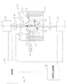
図1は、チョクラルスキー結晶成長装置12とともに使用される例示の制御システム10のブロック図である。例示の本実施形態において、結晶成長装置12は、抵抗ヒータ18又は他の過熱手段によって囲まれたるつぼ16を包む真空チャンバ14を含む。結晶成長装置12は、リフレクタ20も含む。一般的に、るつぼ駆動部22は、矢印24に示されるように、るつぼ16を時計方向に回転させ、さらに、成長プロセス中に望まれるようにるつぼ16を上下動させる。るつぼ16には、単結晶28が引き上げられるシリコン融液26が入れられている。単結晶28は、種結晶30が引き上げシャフト又はケーブル32へ取り付けられて始まり、直径34を有する。単結晶28は、本明細書では結晶インゴットともいう。シリコン融液26は、融液表面36を有するが、融液表面36を結晶の成長中には、融液気体間界面ともいう。るつぼ16と結晶インゴット28とは、ほぼ共通の対称の鉛直軸38を有する。融液基準の高度40は融液気体間界面36と、任意だが固定の参照部と、例えば、これに限定するものではないが、ヒータ18の上部42と、の間の距離として定められる。融液ギャップの大きさ43に対するリフレクタは、融液気体間界面36とリフレクタ20の底部44との間の距離として定められる。また大きさ43は、本明細書では融液ギャップの大きさ、又は融液ギャップとも言う。
FIG. 1 is a block diagram of an
チョクラルスキーの結晶成長プロセスによると、結晶駆動部45は、典型的には、るつぼ駆動部22がるつぼ16を回転させる方向とは逆の方向に、ケーブル32を回転させる。すなわち、結晶駆動部45はケーブル32を第2の方向に回転させ、この方向は矢印46に示されており、るつぼ駆動部22がるつぼ16を回転させる方向とは逆方向である。結晶駆動部45はまた、成長プロセス中に望まれるようにるつぼ16を上下動させる。加熱電力供給部48は抵抗ヒータ18に電圧を加え、そして断熱材50は真空チャンバ14の内壁を補強する。(図示していない)真空ポンプは、真空チャンバ14の内部から気体を取り除くために含まれても良く、これを不活性雰囲気に、例えばアルゴン気体に置き換えて真空チャンバ14内に注入しても良い。冷却水が供給される(図示していない)冷却ジャケットは、結晶インゴット28を取り囲んでも良い。温度センサ52は、例えば限定するものではないが光電セルなどであり、シリコン融液26の温度安定化のために融液表面の温度を計測しても良い。
According to the Czochralski crystal growth process, the
図1の例示の実施形態においては、制御システム10は制御部64に結合する複数のカメラ62を含む。複数のカメラ62は、制御部64との組み合わせにおいて、少なくとも一つの結晶成長パラメータ(すなわち特性)の大きさを測定するよう構成される。結晶の成長特性は、結晶インゴット28の成長中における結晶インゴット28の結晶特性を含んでも良い。これは例えば、限定するものではないが、結晶インゴット28の直径および融液の基準高度40などがある。結晶の成長特性はまた、ホットゾーン特性を含んでも良く、例えば限定するものではないが、融液ギャップ43、リフレクタ20の傾斜、及びリフレクタノッチの中のリフレクタエッジの回転位置などでも良い。制御部64は、温度センサ52からの、また複数のカメラ62からの信号をも処理する。制御部64はまた、本明細書で記載される、結晶の成長制御を促進する他のいかなるセンサからの信号も受信する。制御部64は、プログラム化したデジタルコンピュータ又はデジタルコンピュータに加えてアナログコンピュータを含んでも良い。これは例えば(図2に図示される)処理装置110であり、とりわけ、るつぼ駆動部22、結晶駆動部45及び加熱電力供給部48を制御するために用いられる。
In the exemplary embodiment of FIG. 1, the
更に図1において、典型的なシリコンの単結晶成長プロセスによると、所定量の多結晶シリコンはるつぼ16に詰められる。加熱電力供給部48は、詰められた物を融解させるため、ヒータ18を通して電流を提供する。結晶駆動部45は、ケーブル32を介し、るつぼ16の中に入れられた融解したシリコンであるシリコン融液26に接触するまで種結晶30を下方へ動かす。種結晶30が融解し始めると、結晶駆動部45は、シリコン融液26から種結晶30をゆっくり引き抜き、または引き上げる。種結晶30は、シリコン融液26から引き抜かれるにつれて、結晶インゴット28を生成するためシリコン融液26からシリコンを引き出す。種結晶30がシリコン融液26に接触する前に、まず、種結晶30を予熱するために、シリコン融液26と殆ど接触するまで、種結晶30を下方に動かすことが必要である。
Still referring to FIG. 1, according to a typical silicon single crystal growth process, a predetermined amount of polycrystalline silicon is packed into the
結晶駆動部45は、結晶インゴット28がシリコン融液26から引き上げられる際に基準の速さで、結晶インゴット28を回転させる。るつぼ駆動部22は同様に、るつぼ16を第2の基準の速さにおいて回転させるが、これは普通結晶インゴット28に対して反対方向である。制御部64は、ネックを結晶インゴット28の下方とするよう、まず引き抜き速さ(すなわち引き上げ速さ)を制御し、そして加熱電力供給部48によってヒータ18へ供給される電力を制御する。それで制御部64は、結晶インゴット28の直径38を、コーン形状で増加させるよう、所望の直径34に到達するまでこれらのパラメータを調整する。一度結晶インゴット28が所望の結晶の直径34に到達すると、制御部64は、システム10により計測される中ほぼ一定の直径を維持するよう、このプロセスが終了に近づくまで、引き上げ速さ及び/又は加熱を制御する。その時点においては、制御部64は、直径が、結晶インゴット28の端においてテーパ部を形成して減少するよう、引き上げ速さ及び/又は加熱を増加させる。
The
上記に記載したとおり、結晶の成長プロセスにおいては、精密で信頼できる制御が、特に結晶インゴット28のネック部において望まれる。制御部64は、ネックの直径が、例えば所望の直径の10パーセントの範囲内に留まるよう、ほぼ一定のネックの直径を維持させるように、構成され得る。先行技術に知られるように、種結晶30に近接するネックの上部は、転位の無い種結晶30をシリコン融液26に接触させるのに関連した熱衝撃によって初期に導入される(図示していない)転位を含み得る。ネックの直径における過剰なばらつきはまた、転位を増殖させるおそれもある。図1の実施形態においては、制御システム10は、結晶とるつぼの回転速さを、例えば結晶の長さおよび/または結晶の直径の関数として制御するよう構成される。
As described above, precise and reliable control is desired in the crystal growth process, particularly at the neck of the
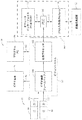
図2は、(図1に示される)制御システム10の例示の実施形態のブロック図である。図2の例示の実施形態においては、制御システム10は複数のカメラ62と制御部64とを含む。例示の実施形態では、複数のカメラ62は第1のカメラ80及び第2のカメラ82を含む。第1のカメラ80は、少なくとも一つの画像センサ84を含み、画像センサ84上に光の焦点を合わせるよう構成されるレンズ86と結合する。同様に、第2のカメラ82は、少なくとも一つの画像センサ88を含み、画像センサ90上に光の焦点を合わせるよう構成されるレンズ88と結合する。図2の例示の実施形態においては、制御システム10はまた、制御部64と複数のカメラ62との間に結合するビジョンシステム92を含む。これに代わる実施形態において、ビジョンシステム92は制御部64の内部に含まれても良い。例示の実施形態においては、複数のカメラ62は、(図1に示される)チャンバ14のビューポート(例えば窓)に、(図1に示される)鉛直軸38に対して約15度か25度の角度において搭載される。そして複数のカメラ62は、一般的には(図1に示される)融液気体間界面36における鉛直軸38の(図1に示される)シリコン融液26との交差点に照準を合わされる。融液気体間界面36は、結晶の成長プロセス中、成長する結晶の画像内においてブライトリングを位置づけることにより同定され得るが、ここでブライトリングは、照り返すシリコン融液26上のホットゾーン構成部の少なくとも一部による反射である。
FIG. 2 is a block diagram of an exemplary embodiment of control system 10 (shown in FIG. 1). In the exemplary embodiment of FIG. 2, the
図2の例示の実施形態においては、ビジョンシステム92はまた、伝送線96(例えばビデオグラフィックスアレイ(VGA)やデジタルビジュアルインターフェイス(DVI)ビデオケーブル)を介してビデオ画面94と、さらには伝送線102(例えばRS−232ケーブル)を介してパーソナルコンピュータ100と、通信する。ビデオ画面94は、第1のカメラ80と第2のカメラ82の内の少なくとも一つによって生成されたビデオ画像を表示し、そしてパーソナルコンピュータ100はビジョンシステム92をプログラムするため用いられる。
In the exemplary embodiment of FIG. 2, the
制御部64は、処理装置110を含む。より明確には、ビジョンシステム92が処理装置110に結合される。処理装置110は、以下プロセッサとも言い、限定するものではないが、中央処理装置、マイクロプロセッサ、マイクロコントローラ、プログラマブル論理制御装置(PLC)、縮小命令セット回路(RISC)、特定用途向け集積回路(ASIC)、論理回路、および本明細書に記載の機能を実行可能である、いかなる他の回路又はプロセッサを含んでも良い。処理装置110は、伝送線114(例えばRS−232ケーブル)を介してオペレータインターフェイスコンピュータ112と通信し、そして伝送線118(例えばRS−485ケーブル)を介して一つかそれ以上のプロセス入力/出力モジュール116と通信する。オペレータインターフェイスコンピュータ112は、結晶成長装置12のオペレータが特定の結晶を成長させるための所望のパラメータのセットを入力することを許容する。プロセス入力/出力モジュール116は、成長プロセスを制御するための結晶成長装置12との往復経路を提供する。例として、処理装置110は、(図1に示される)温度センサ52から融解温度に関する情報を受信し、そして融解温度の制御とそれによる成長プロセスの制御のため、プロセス入力/出力モジュール116を介して(図1に示される)加熱電力供給部48へ制御信号を出力する。更には、処理装置110は複数のカメラ62からデータを受信し得、ビジョンシステム92によるビジョンシステムの解析を介し、そのデータから結晶の直径を測定し得る。そして種結晶30がシリコン融液26から引き抜かれる速さを制御し、それによって成長プロセスを制御するため、処理装置110は、プロセス入力/出力モジュール116を介して(図1に示される)結晶駆動部45へ制御信号を出力し得る。
The control unit 64 includes a
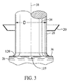
図3は、シリコン融液26から引き上げられる結晶インゴット28の部分図である。結晶インゴット28は、一般的に鉛直軸38と直径34とを有する結晶シリコンの円筒体を構成する。結晶インゴット28などの成長中の結晶は、一般的には円筒状であるが、一様な直径を有していなくても良い。このような理由で、直径34は鉛直軸38に沿って異なる角度位置においてわずかに変化しても良い。更に、直径34は結晶成長の様々な相、例えば種、ネック、クラウン、肩、体、そして端部の錐などにおいて変化し得る。例示の実施形態においては、第1のカメラ80と第2のカメラ82はそれぞれ、下側の終端が融液固体間界面119にある成長結晶のビデオ画像を生成する。融液固体間界面119は、融液気体間界面36へ隣接し、湾曲した液体のメニスカス120によって融液気体間界面36へ接続される。結晶駆動部45がシリコン融液26から結晶インゴット28を引き上げるにつれ、メニスカス120は、結晶インゴット28の持ち上げによって形成される。メニスカス120は、ビデオ画像内で明るい環状の反射として同定される。明るい環状の反射は、本明細書では(図7及び8に示される)「ブライトリング」と称する。ブライトリングは、照り返すメニスカス120上の、より熱いホットゾーン構成部の反射であり、例えばるつぼ16の壁の反射である。画像においてブライトリングを同定することは、メニスカス120の物理的形状を介して融液固体間界面119の位置の測定することを容易化する。
FIG. 3 is a partial view of the
第1のカメラ80及び第1のカメラ80は、少なくとも一つの伝送線(例えばRS−170ビデオケーブルやユニバーサルシリアルバス(USB)ケーブルなど)を介して、ビジョンシステム92へとビデオ画像を通信するが、この伝送線は、例えばそれぞれ第1の伝送線130及び第2の伝送線132である。例示の実施形態において、ビジョンシステム92は画像プロセッサ142を含む。
The
図2の例示の実施形態においては、第1のカメラ80及び第2のカメラ82はディスクリートなデジタルカメラである。第1のカメラ80は、例えば限定するものではないが、USB接続などのシリアル通信を用いてビジョンシステム92へ結合しても良い。その代わりに、第1のカメラ80は、パラレル通信を用いてビジョンシステム92へ結合しても良い。第1のカメラ80、第2のカメラ82、及び関連したレンズ86と90は、同一のデザイン及び/又はモデル番号のものであっても良いのだが、第1のカメラ80及び第2のカメラ82は、独立したカメラ調整がそれぞれのカメラにおいて行われる限りにおいて再現可能な結果を生成するため、同一の技術を含まなくても良い。代わりの実施形態においては、第1のカメラ80及び/又は第2のカメラ82はモノクロの電荷結合素子(CCD)カメラであり、これは解像度768×494ピクセルでアナログ出力であるSony(登録商標)社製XC−75CCDビデオカメラなどであって、例えば限定するものではないがRS−170である。代わる実施形態では、ビジョンシステム92は、RS−170カメラと画像プロセッサ142との間に結合されるフレーム取り込みカード144を含む。
In the exemplary embodiment of FIG. 2, the
フレーム取り込みカード144を備えるRS−170カメラなどの、ディスクリートでないデジタルカメラのタイプが用いられ得るのだが、それらはデータの伝送ノイズは元より、ビデオ及び画像化雑音によって望ましくない。例えば、フレーム取り込みカード144に伝送される低いアナログ信号基準は、結晶成長装置12を取り囲む環境など、電気的ノイズ環境の中でビデオノイズの増大をもたらす。カメラが順次走査式カメラでなく、インタレースカメラであれば、別のビデオ線を用いるにおいて輝度の変動が起こり得、エッジの検知ノイズを引き起こす。また、フレーム取り込みカード144は、例えば第1のカメラ80などからのビデオデータ読み出しタイミングと、厳密には一致しない可能性のあるタイミングにおいて、水平線のデジタル化を生成する。そのため、アナログ式RS−170ビデオ信号のフレーム取り込みデジタル化は、線のスキャン方向における時間的圧縮/拡張によって、寸法境界の検知においてバイアス、ドリフト、及び/又はノイズを生成し得る。計測の方向に依存して、バイアス、ドリフト、及び/又はノイズは、所望の結晶成長パラメータを計測する精密さを低下させる効果を備え得る。シリアル(USB等)又はパラレル式のデジタルカメラは、周囲の電気ノイズによって影響されがちでない、より高いレベルのデジタル信号を伝送する。
Although non-discrete digital camera types such as an RS-170 camera with a
加えて、デジタルカメラにおける個々のピクセルの座標的なアドレス指定は、デジタル化されたタイミング差とインタレースノイズとによって境界検知の変動を防ぐ。デジタル化されたタイミング差とインタレースノイズとの各々は、RS−170カメラを用いると観測され得る。更には、成長する結晶の画像化は、より高い速度の動作を幾つか含み、例えば融液の振動、結晶の揺れ、そして特に結晶の回転を含む。通常のファセットの外観は、結晶インゴット28の表面上の小さな上昇線として見え得るが、これに加え、幾つかの結晶インゴットはまたねじ状や螺旋状の外観、大きな平坦部、又はその他の円筒モデルにフィッティングする困難を増大させる表面上の歪みを備え得る。高速動作が存する中での数学的なモデル形状の精密な三次元フィッティングは、多数のカメラからのカメラ画像を撮像するタイミングにおける差により、更に悪化させられる。多数のRS−170カメラシステムは、それぞれカメラの信号が同一のフレーム取り込み部、例えばフレーム取り込みカード144を介して送られるが、タイミングに差を有し得る。この差は、例えば第1のカメラからと第2のカメラからとのカメラの信号間に1秒の1/30又は1/15、といったものである。15RPMの結晶の回転において、1秒の1/30又は1/15のタイミング遅延は、結晶の回転の3度から6度を表し得る。そのため、素早く動く場面において、結晶の歪みの画像を非同時的に撮像することは、例えば広い平坦部を備える結晶が素早く回転するとき等であるが、カメラが撮像する位置の差によって、計測ノイズを増大させ得る。高速で動作する場面の変化によるフィッティングのエラーは、シリアル又はパラレル式のデジタルカメラ上で同時に画像を撮像するための、外部のトリガー信号を用いて、非常に同時に近い画像の撮像を行うことにより、補正され得る。高速の露光時間(1/250秒または1/1000秒など)が用いられても良く、これは結晶成長装置12に存する高い光源レベルのため、静止動作に近い画像を提供する。製造環境において更に考慮すべきことは、CCDカメラにフレーム取り込みカード/ボード又は多数のフレーム取り込みカード/ボードを加えた物と比べて、シリアル式デジタルカメラの一般的により低い費用である。
In addition, the coordinate addressing of individual pixels in a digital camera prevents boundary detection variations due to digitized timing differences and interlace noise. Each of the digitized timing differences and interlace noise can be observed using an RS-170 camera. Furthermore, imaging of growing crystals includes some higher speed motions, including, for example, melt vibration, crystal shaking, and especially crystal rotation. The normal facet appearance may appear as a small rising line on the surface of the
図4は、(図1及び2に示される)制御システム10に用いられる例示のデュアルカメラアセンブリ160の斜視図である。図4の例示の実施形態においては、デュアルカメラアセンブリ160は、カメラ搭載システム162と2台のカメラ、例えば第1のカメラ80及び第2のカメラ82と、を含む。カメラ搭載システム162は、物理的に第1のカメラ80及び第2のカメラ82と、(図1に示される)結晶成長装置12へ、又は(図5に示される)カメラ調整システム170へ結合する。図4の例示の実施形態においては、カメラ搭載システム162は共通プレート164を含み、その上へ物理的に第1のカメラ80及び第2のカメラ82が結合される。プレート164はセラミックでも良く、例えば適度な温度のガラス雲母セラミックや、適切な温度環境において、第1のカメラ80及び第2のカメラ82のお互いに対する及び/又は結晶成長装置12に対する安定な結合を容易化する、いかなる他の適切な材料であっても良い。第1のカメラ80及び第2のカメラ82は、固定部材、例えば4つの搭載スクリューの各々によって、プレート164へ結合される。そして、プレート164は結晶成長装置12に、且つカメラ調整システム170に対して同じ程度の高さとなる。
FIG. 4 is a perspective view of an exemplary
より具体的には、カメラ搭載システム162は、第1のカメラ80及び第2のカメラ82を調整システム170に結合し、そして調整の後には、第1のカメラ80の第2のカメラ82に対する位置を変えず、世界の回転の精密な応答を伴って、第1のカメラ80及び第2のカメラ82を結晶成長装置12にも結合する。更には、第1のカメラ80及び第2のカメラ82は、カメラ搭載システム162によって、第1のカメラ80及び第2のカメラ82が結晶成長装置12に対して位置付けられるのと同じ程度に、調整システム170に対して位置付けられる。さらには、カメラの焦点が調整手順の後または最中に変化することから防ぐため、カメラレンズの焦点リングが、焦点を大体、操作する対象の距離に設定した後、レンズ体に確保されても良い。例えば、カメラレンズの焦点リングは、焦点を大体、操作する対象の距離に設定の後、レンズ本体へ、接着および/またはねじ留めされても良い。高温における結晶の成長は一般的にカメラのデザイン仕様に対して明るい環境を提供するため、カメラのFストップは、操作においてほとんど閉じており、大きな操作の被写界深度を提供する。カメラのFストップは、調整システム170と結晶成長装置12との間で異なり得、例えば、調整システム170によって結晶成長装置12よりも低い明るさを提供する。カメラ80及び82が、調整システム170又は結晶成長装置12の範囲内で配置されるときの飽和状態において動作しない場合、カメラのFストップの変化は調整及び/又は計測の精度に、悪い方向に影響を及ぼさない。
More specifically, the
図5は、調整システム170の例示の実施形態の斜視図である。図5の例示の実施形態において、調整システム170は、カメラ搭載システム162を調整システム170に対して確実に結合させるように構成される搭載面172を含む。調整システム170はまた、ターゲット面174も含む。調整ターゲット176はターゲット面174に配置され、及び/又は固定される。図5の例示の実施形態において、調整ターゲット176は、プラスチックであり、既知の大きさの方形を有する調整グリッドがインプリントされている。調整ターゲット176は、接着剤を用い、ガラスの重量で押し下げ、又は調整ターゲット176を平坦にターゲット面174に対して維持し、そしてターゲット面174に対し固定するのを容易化するいかなる他の方法で、ターゲット面174に対して固定されても良い。プラスチックとして記載したが、調整グリッドは紙上にインプリントされ、金属中にエッチングされ、又は調整システム170が本明細書に記載された作用を行うことができるいかなる他の方法において形成されても良い。しかしながら、湿度によって起こる大きさの変化の効果は、紙上に最も大きい効果を有し得、調整ターゲット176の精密性に悪い影響を及ぼし得る。
FIG. 5 is a perspective view of an exemplary embodiment of
調整システム170は、カメラ搭載システム162とターゲット面174を、固定された相対位置において維持する。カメラ搭載システム162が(図1に示される)結晶成長装置12に対して結合されるとき、この位置は、カメラ搭載システム162の(図1に示される)融液気体間界面36に対する相対位置に合致する。
The
(図1に示される)結晶成長装置12から分離した固定物として記載したが、第1のカメラ80及び第2のカメラ82の調整は、結晶成長装置12内部に含まれる調整システムを用いて実行されても良い。図5の例示の実施形態において、第1のカメラ80及び第2のカメラ82は、専用のカメラの調整システム170を用いて調整される。しかしながら、調整の他の方法は、基本的に、ここに記載するシステムおよび方法の本質を変えず、むしろ単に動作上のリスクを変えるに過ぎない。第1のカメラ80及び第2のカメラ82の調整は、本明細書に記載の方法及びシステムについて特に重要である。なぜなら、調整をずらすこと(例えば、レンズの再配置、カメラの不具合および再配置などによるもの)は、何時でも起こり得るものであり、再調整を実行するのに冷たい溶融炉は使用可能でないため、結晶を動かす一連の範囲内で非精密度の高いカメラの計測を起こしてしまう可能性があるからである。
Although described as a fixed object separated from the crystal growth apparatus 12 (shown in FIG. 1), adjustment of the
カメラの調整は、レンズを加えたカメラの固有の及び付帯的なパラメータのセットの生成である。カメラ画像のピクセルの、一般的に非常に正確な間隔を知り、様々な移転および/または向きにおける正確なターゲット(例えば、調整ターゲット176)の一連の画像を使用することにより、カメラの調整パラメータは、特定のレンズおよびカメラの組み合わせにおいて生成され得る。カメラの調整パラメータは例えば、実際のレンズの焦点距離、レンズの収差、ターゲットに対するカメラの向き、及び投影行列係数の推定値を表す。例えば、第1のカメラ80及びレンズ86がカメラ搭載システム162に対して結合されている場合、カメラの調整パラメータの第1のデータセットは、調整システム170を用いた第1のカメラ80及びレンズ86の組み合わせにおいて生成される。更には、カメラの調整パラメータの第2のデータセットは、調整システム170を用いた第2のカメラ82及びレンズ90の組み合わせにおいて生成される。この情報とともに、ターゲット特性の間隔及び相対的な高度についての精密な寸法の情報に加えて、数学的モデルの座標の画像が、既知の向き付けを有するカメラの画像上に、精密に数学的に射影され得る。カメラ調整の数学の刊行された例には、非特許文献1及び非特許文献2がある。カメラの調整パラメータを含む調整データファイルは、カメラ/レンズの組み合わせそれぞれにおいて生成され得、または個々のカメラ調整データファイルは単一のファイルへ連結され得る。そしてこのファイル又はこれらのファイルは、デュアルカメラアセンブリ160とともに結晶成長装置12へ移される。
Camera adjustment is the generation of a set of intrinsic and incidental parameters of the camera plus the lens. By knowing the generally very precise spacing of the pixels of the camera image and using a series of images of the correct target (eg, adjustment target 176) in various transfers and / or orientations, the camera adjustment parameters are Can be generated in certain lens and camera combinations. Camera adjustment parameters represent, for example, the actual lens focal length, lens aberration, camera orientation relative to the target, and projection matrix coefficient estimates. For example, if the
図5の例示の実施形態において、カメラアセンブリの調整は、ターゲット面174及び調整ターゲット176を動かすことによって実行される。このターゲットは水平にされ、正確に計測されたターゲットであって、多数の高度を縦に通り、それぞれの高度において第1のカメラ80及び第2のカメラ82を用いて画像を撮像するために停止する。以上に記載のとおり、調整ターゲット176はグリッド状又は丸いターゲット点を含み得る。ターゲット点の中心または画像上のターゲットグリッドとの交差部分は、解析ソフトウェアを用いてそれぞれの画像の範囲内で、サブピクセル解像度の範囲内へと位置取られる。そして、これらの交差部分、加えて仮定した世界の原点(例えば第1の高度上のターゲットの中心位置)に対する交差部分それぞれの座標の正確な物理位置は、それぞれのカメラ/レンズの組み合わせにおける、固有の及び付帯的なレンズを加えたカメラの調整パラメータを決定するカメラの調整ソフトウェアによって、解析される。
In the exemplary embodiment of FIG. 5, adjustment of the camera assembly is performed by moving
デュアルカメラアセンブリ160は、そうしてカメラの調整パラメータを含む調整データファイルとともに結晶成長装置12へ移され、あるビューポートにおいて、例えば(図示していない)単結晶引き上げウィンドウにおいて、結晶成長装置12に備え付けられる。多数のウィンドウが用いられても良いが、多数のウィンドウを展開するにはより大きな(図4に示される)カメラ搭載システム162が要求され得る。そしてデュアルカメラアセンブリ160は、調整固定物の回転のリファレンスと合致する精密な回転のリファレンスを提供するよう、正確に再び水平化される。そこで、オンラインのフィッティングソフトウェアは、(図7及び図8に示される)画像220及び画像222内部でのブライトリング226の端部224の同定によって位置づけられる、成長するシリコン結晶の照り返すメニスカス120(図3に示される)の高度及び直径を解析するために用いられる。ホットゾーン構成部の特性、例えば(図1に示される)リフレクタ20の特性も、リフレクタ高度の推定など相対的な寸法の情報を提供するために解析されても良い。融液基準の高度40及びリフレクタ高度の推定は、融液ギャップ43を推定するために、そしてインゴットの一様な品質の増大および/またはインゴットの寸法の制御の改善において結晶成長装置12の動作を制御するのに用いられる、動作パラメータを調整するために、順次用いられ得る。
The
調整パラメータを調整システム170から結晶成長装置12へ精密に移すため、カメラ80及び82が整列されるリファレンスの方向は、調整システム170と結晶成長装置12双方に関して要求される。重力ベクトルが、調整システム170と結晶成長装置12双方において利用可能であるため、調整システム170上と結晶成長装置12上双方において、カメラ80及び82に対して堅く取り付けられた表面を水平化する正確さは、調整システム170上に在ったカメラ80及び82の方向を結晶成長装置12上で複製するのに用いられ得る。重力によってシリコン融液26は平均的に基準面を、結晶の成長が一般的にはその表面に垂直となるよう維持するため、調整ターゲット176も融液表面上に計測点をシミュレートするため水平化される。調整ターゲット176の精密な鉛直移動の準備がされるならば、画像は多重の高度において同一のターゲットを撮像され得る。画像は正確に位置づけられた三次元画像データのセットを生成し、そのセットは正確なカメラの調整パラメータを生成するため用いられる。
In order to precisely transfer the adjustment parameters from the
図6は、複数のカメラ62を含む(図2に示される)制御システム10の一部の数学的モデルの図である。図6の例示の実施形態においては、複数のカメラ62は第1のカメラ80及び第2のカメラ82を含み、(図1に示される)結晶成長装置12のビューポートに位置づけられる。第1のカメラ80は画像平面180上において画像を撮像し、第2のカメラ82は画像平面182上において画像を撮像する。図7は、制御システム10の第1のカメラ80によって撮像される、例示の画像220である。図8は、制御システム10の第2のカメラ82によって撮像される、例示の画像222である。
FIG. 6 is a diagram of a mathematical model of a portion of the control system 10 (shown in FIG. 2) that includes a plurality of
例示の実施形態において、現実世界の数学的モデル200は世界のリファレンス原点202辺りに中心が置かれる。数学的モデル200は、複数のモデルのサンプル点204を含んでおり、例えば第1のモデルのサンプル点206及び第2のモデルのサンプル点208である。複数のサンプル点204は、少なくとも結晶成長の特性の一つと対応し、例えば限定するものではないが、(図1に示される)結晶の直径34と(図1に示される)融液基準の高度40とについての情報を含むブライトリングに沿ったサンプルである。x軸210、y軸212及びz軸214を含む三次元座標系が示されているが、先行技術において知られる他の座標系が、数学的モデル200を規定するのに用いられても良い。数学的モデル200は、結晶の成長特性について代表的で再現可能な計測の提供を促進するため、結晶成長装置12内部の結晶成長の期待値と一般的に合致するよう生成される。例示の実施形態において、数学的モデル200は、高度の所定範囲に渡るブライトリングの半径に実質的に合致すると期待される側面216を有する円筒状のモデルである。円筒に沿った高度または円筒の直径の変化が成されるときに、数学的モデル200は、複数のモデルのサンプル点204それぞれの、画像平面180及び182へのピクセル射影の感度を含んでも良い。入力点の範囲内での変化により出力が変化することを予言する感度行列は、しばしばヤコビアン行列と呼ばれる。
In the illustrated embodiment, the real-world
(図7に示される)結晶インゴット28の第1の画像は、(図7に示される)画像平面180上で(図6に示される)第1のカメラ80によって撮像される。ブライトリング226の端部224は、第1の画像220内部に同定される。以上に記載のとおり、ブライトリング226は(図3に示される)メニスカス120上のホットゾーン構成部の反射である。第1の画像220におけるブライトリング226の端部224を同定することは、(図3に示される)融液気体間界面36の位置決定を容易化する。結晶インゴット28の(図8に示される)第2の画像222は、(図6に示される)第2のカメラ82によって(図6に示される)画像平面182上に撮像される。ブライトリング226の端部224も、第2の画像222内に同定される。例示の実施形態において、モデルのサンプル点204は画像平面180及び画像平面182上に数学的に射影される。より具体的には、モデルのサンプル点206及びモデルのサンプル点208が、第1の画像220上へと射影される。モデルのサンプル点206及びモデルのサンプル点208は、第2の画像223上へも射影される。少なくとも一つのサンプル点は、例えばサンプル点228,230及び232は、モデルのサンプル点206の組み合わせの中でサンプリング線234を形成するが、これは第1の画像平面180上に射影される。サンプリング線234は数学的モデル200の側面216の接線、及びモデルのサンプル点206から(図6に示されない)第1のカメラ80のレンズ86の中心への経路に、直交する。更に、少なくとも一つのサンプリング点は、例えばサンプリング点242,244及び246は、モデルのサンプル点206の組み合わせの中でサンプリング線248を形成するが、これは第2の画像平面182上に射影される。サンプリング線248は側面216の接線、及びモデルのサンプル点206から(図6に示されない)第2のカメラ82のレンズ90の中心への経路に、直交する。
A first image of the crystal ingot 28 (shown in FIG. 7) is taken by the first camera 80 (shown in FIG. 6) on the image plane 180 (shown in FIG. 7). An
図9は、結晶の、例えば(図1に示される)シリコン融液26から引き上げられる(図1に示される)結晶インゴット28の、結晶成長中における少なくとも一つの結晶成長特性の三次元的計測のための例示の方法252のフローチャート250である。例示の実施形態においては、方法252はコンピュータに実装された方法であり、例えば、ワークステーション及び/又はパーソナルコンピュータ、例えば(図2に示される)プロセッサ110によって実行されるコンピュータに実装された方法である。別の実施形態においては、コンピュータ読み取り可能な媒体上に実現されたコンピュータプログラムが、少なくとも一つのコードセグメントを含んでおり、これはコンピュータに実行されるとき方法252を実行する。第1のカメラは、例えば(図2に示される)第1のカメラ80は、第1の画像平面、例えば(図6に示される)第1の画像平面180上に、結晶インゴット28の第1の画像を撮像する。第2のカメラは、例えば(図2に示される)第2のカメラ82は、第2の画像平面、例えば(図6に示される)第2の画像平面182上に、結晶インゴット28の第2の画像を撮像する。第1のカメラ80及び第2のカメラ82は、既に調整されており、複数の特性のサンプル点と、下記の複数のモデルのサンプル点の少なくとも一つにおける法線方向と、を決定するのに用いられる調整パラメータのデータセットの生成を含む。
FIG. 9 illustrates a three-dimensional measurement of at least one crystal growth characteristic during crystal growth of a crystal, for example a crystal ingot 28 (shown in FIG. 1) pulled from a silicon melt 26 (shown in FIG. 1). FIG. 26 is a
方法252は、数学的モデル、例えば結晶の成長中における結晶インゴット28の(図6に示される)数学的モデル200の生成260も含む。以上に記載のとおり、数学的モデル200は、結晶インゴット28の少なくとも一つの特性に対応する(図6に示される)複数のモデルのサンプル点204を含む。その少なくとも一つの特性は、限定するものではないが、(図3に示される)融液気体間界面36を含んでも良い。数学的モデル200内に含まれるのは、少なくとも一つの特性の寸法であり、これは限定するものではないが、(図1に示される)結晶の直径34と(図1に示される)融液基準の高度40とを含んでいる。数学的モデル200の生成260は、仮定された数学的モデルのリファレンス、例えば(図6に示される)モデルのリファレンス点202の生成を含み、その上に数学的モデル200が集められる。例示の実施形態において、数学的モデル200は、結晶の成長プロセス内での特定の時間における、結晶の直径34および融液基準の高度40の内の少なくとも一つの仮定を含む。例示の実施形態においては、数学的モデル200は、結晶成長中の結晶インゴット28の与えられた直径におけるブライトリングの高度の位置と、それぞれ三次元座標を備えるモデル点204と、を表す。
The
図9の例示の実施形態においては、方法252は、第1の画像、例えば(図7に示される)第1の画像220、及び第2の画像、例えば(図8に示される)第2の画像222の内部における少なくとも一つの結晶の成長特性の検知264も含む。結晶の成長特性は、限定するものではないが、融液気体間界面36を含んでも良く、(図7及び8に示される)ブライトリング226の存在によって同定される。方法252は、第1の画像220内で結晶の成長特性に対して数学的モデル200を比較することによる第1のエラー値の検知266も含む。方法252は、第2の画像222内で結晶の成長特性に対して数学的モデル200を比較することによる第2のエラー値の検知268も含む。
In the exemplary embodiment of FIG. 9, the
方法252は、決定された第1のエラー値及び第2のエラー値を最小化するよう、数学的モデル200を調整することによって、少なくとも一つの結晶成長特性に関連づけられた見積もりの三次元的(3D)計量値の生成270も、含んでも良い。2台のカメラを用いるとき、カメラの射影は同一直線状になり得ないため、数学的モデル200において直交するエラーについて、2つのエラーの中に情報が存在する。換言すると、第1の決定されたエラー値及び第2のエラー値は、少なくとも一つの結晶成長特性に関連づけられた見積もりの3D計量値を決定するように組み合わせにおいて用いられる。少なくとも一つの結晶成長特性に関連づけられた見積もりの3D計量値の生成270は、限定するものではないが、結晶の直径34、融液基準の高度40及び/又はリフレクタ特性の高度であって、そこからのリフレクタ融液間の(図1に示される)高度ギャップの距離43が生成され得るものの生成270を含んでも良い。例えば、見積もりの3D計量値の生成270は、数学的モデル200において2つのカメラ画像220及び222内の端部を備えたエラーを最小化するためにモデルのパラメータを変えるよう、逆射影のヤコビアン行列による第1のエラー及び第2のエラーを反復して乗算することを含んでも良い。
The
見積もりの3D計量値の生成270は、所定のエラー基準に対する第1のエラー値および/または第2のエラー値の比較も含んでも良い。所定のエラー基準は、数学的モデル200が、第1の画像220および/または第2の画像222内部に同定される結晶の成長特性に実質的に合致するエラーの基準である。例えば、エラーが所定のエラー基準より小さいか等しい場合、少なくとも一つの結晶成長特性の見積もりの寸法は、数学的モデル200内部のデータに基づいて生成270されても良い。第1のエラーおよび/または第2のエラーが所定の基準以下であることを決定することは、数学的モデル200が実際の結晶インゴット28の十分に精密なモデルであることを示す。そしてこれにより、数学的モデル200内にある寸法は、結晶成長特性の実際の寸法に対応するとして信頼し得る。見積りの寸法は、結晶成長装置12の制御において用いられる。例えば、見積もりの寸法が(図1に示される)制御部64に提供され、そして結晶成長装置12の動作パラメータを決定するのに用いられても良い。
Estimated 3D
一様に近い高度の円弧は、結晶成長装置12内部のメニスカスの反射(すなわちブライトリング226)を検知するのに用いられても良い。代わりの実施形態においては、ブライトリング226は、(図1に示される)るつぼ16に加熱の輝度が加わったものの仮想的な画像であることから、融液気体間界面36上方のカメラの交差部分が、メニスカスの形状に基づいて更なる計測精度の改善のために計算されても良い。融液気体間界面36上方のカメラの交差部分を決定する方法の例は、非特許文献3に記載されている。フィッティングされるメニスカスの形状が、しばしば結晶の歪みに影響される場合、より一般的な形状のフィッティング、例えばスプラインフィッティングが用いられ得る。スプラインフィッティングは、非特許文献4に記載されている。代わる実施形態においては、リフレクタの特性も測定される。リフレクタの特性の例は、限定するものではないが、物理的に直線状の鋭い形状、線形の丸い隆起、点状の特性、又は弧形状において形成される線形特性のいずれか、を含む。そのようなリフレクタの特性は、リフレクタの傾斜、(図1に示される)鉛直軸38まわりのリフレクタの回転、及び鉛直軸38からのリフレクタ横方向のオフセットを決定するのに用いられ得る。弧の半径に接する、基準の弧及び基準の直線を含む数学的モデルは、リフレクタの特性を検知するのに十分であり得る。しかしながら、リフレクタの傾斜の計測も望まれる場合、モデルのパラメータは傾斜の見積もりのためのリフレクタのモデルに加えられても良い。加えて、リフレクタの特性がリフレクタにおけるカメラ中心のノッチ内に含まれる場合、ノッチの側面は、直線状の端部特性の高度を見積もる精密さを改善するよう、リフレクタの回転を測定するのに用いられても良い。そしてインゴットのサンプリング位置はこれによって、ノッチの境界内に維持するよう調節され得る。
Nearly uniform altitude arcs may be used to detect meniscus reflections within crystal growth apparatus 12 (ie, Breitling 226). In an alternative embodiment, the
第1のエラー及び第2のエラーは、逆射影のヤコビアン行列によって乗算され、実際の結晶成長特性の大きさに対して漸近的に安定な近似を得るのに、十分低いゲインとなる。結晶成長特性の寸法は、本明細書では計量値とも称し、限定するものではないが、融液基準の高度40、結晶インゴット28の調整された直径34、及び既知の半径若しくは直径又はリフレクタノッチ内のリフレクタ端部の回転位置を有するリフレクタ端部の高度のような他のホットゾーン特性の高度を含んでも良い。リフレクタ端部の高度と融液基準の高度40との比較は、結晶成長の寸法のキー、例えば(図1に示される)融液ギャップ43の精密で再現可能な計測を提供する。そのようなリフレクタ融液間表面ギャップは、融液の流れるパターン及び結晶インゴット28が成長する勾配に影響することが知られる。キーである結晶プロセスの寸法の精密で再現可能な計測は、結晶を処理する調整、例えばるつぼの持ち上げ速さの調整を、キーの結晶プロセスの寸法に基づき、容易化する。
The first and second errors are multiplied by the backprojected Jacobian matrix, resulting in a sufficiently low gain to obtain an asymptotically stable approximation to the magnitude of the actual crystal growth characteristics. The dimensions of crystal growth characteristics, also referred to herein as metric values, include, but are not limited to, melt-based
第1のエラー値および/または第2のエラー値が所定のエラー基準よりも大きい場合、数学的モデル200は実際の結晶成長特性と十分に適合しない。そしてそのため、数学的モデル200は結晶インゴット28の寸法を精密に表すものとして信頼することができない。例示の実施形態において、見積もりの3D計量値の生成270は、更に、数学的モデル200と実際の結晶成長の受信した画像との間のエラーを補間するよう、数学的モデル200を調整することを含む。数学的モデル200は、以下の数式を用いて調整されても良い。
If the first error value and / or the second error value is greater than a predetermined error criterion, the
![]()
![]()
逆ヤコビアン近似dW/diは、感度行列の射影であるが、ゲイン行列Gと第1及び第2のカメラ画像のエラーとによって乗算される。例示の実施形態において、ゲイン行列Gの対角成分は、1より小さい値を有し、計測の見積もりに対する漸近近似を与えるよう選ばれる。ゲイン行列における大きな値は、ゲイン行列がフィードバックループに含まれるため、計測の不安定性を引き起こす。ゲインと逆ヤコビアン近似は、カメラ/レンズの組み合わせの調整中に生成される。 The inverse Jacobian approximation dW / di is a projection of the sensitivity matrix, but is multiplied by the gain matrix G and the errors of the first and second camera images. In the illustrated embodiment, the diagonal component of the gain matrix G has a value less than 1 and is chosen to give an asymptotic approximation to the measurement estimate. A large value in the gain matrix causes measurement instability because the gain matrix is included in the feedback loop. Gain and inverse Jacobian approximation are generated during adjustment of the camera / lens combination.
調整された数学的モデルは、複数の調整されたモデルのサンプル点を含む。複数の特性標準点は、複数の調整されたモデルのサンプル点の内少なくとも一つにおいて決定される。複数の特性標準点と、複数の調整されたモデルのサンプル点の内少なくとも一つとは、調整されたサンプリング線を規定する。調整されたサンプリング線は、第1の画像平面180上へ射影される。サンプリングは、第1の画像220の範囲内にてブライトリング226の端部224の位置を測定するよう、サンプリング線に沿って実行される。第1のエラー値は、調整されたモデルのサンプル点の位置に対し、第1の画像220の範囲内にてブライトリング226の端部224の位置を比較することによって決定される。調整されたサンプリング線は、第2の画像平面182上にも射影される。サンプリングは、第2の画像222の範囲内にてブライトリング226の端部224の位置を測定するよう、サンプリング線に沿って実行される。第2のエラー値は、調整されたモデルのサンプル点の位置に対し、第2の画像222の範囲内にてブライトリング226の端部224の位置を比較することによって決定される。調整されたモデルのサンプル点と、第1の画像220の範囲内および/または第2の画像222の範囲内のブライトリング226の端部224との間におけるエラーが、例えば所定のエラー基準より小さいと決定されれば、調整されたモデルのサンプル点に基づく結晶特性の見積もりの寸法は、制御部64に出力される。
The adjusted mathematical model includes a plurality of adjusted model sample points. The plurality of characteristic standard points is determined at at least one of the plurality of adjusted model sample points. The plurality of characteristic standard points and at least one of the plurality of adjusted model sample points define an adjusted sampling line. The adjusted sampling line is projected onto the
図10は、(図9に示される)第1のエラー値の決定266と第2のエラー値との決定268における例示の動作のフローチャート300である。図10の例示の実施形態においては、第1のエラー値の決定266は、複数のモデルのサンプル点204の少なくとも一つ、例えばモデルのサンプル点206における、第1の複数の特性標準点、例えば(図7に示される)特性標準点228,230及び232の決定310を含む。特性標準点228,230,232及びモデルのサンプル点206は第1のサンプリング線、例えば(図7に示される)サンプリング線234を規定する。サンプリング線234は、複数の特性標準点228,230,232及びモデルのサンプル点206を含む。例示の実施形態においては、サンプリング線234は、数学的モデル200の(図6に示される)側面216の接線、及びモデルのサンプル点206から第1のカメラ80のカメラのレンズ86の中心への経路に直交する。
FIG. 10 is a
例示の実施形態においては、第1のエラー値の決定266は更に、第1の画像平面180上へのサンプリング線234の射影312を含む。決定266は、ブライトリング、例えば第1の画像220内の(図7に示される)ブライトリング226の高輝度の端部の位置を決定するための、サンプリング線234に沿ったサンプリング314も含む。第1のエラー値の決定266は、モデルのサンプル点206の位置に対する第1の画像220内におけるブライトリング226の位置の比較316も包含する。換言すると、第1のエラーは、第1の画像220におけるサンプリング線234に沿ったブライトリング226の位置と数学的モデル200に従うブライトリング226の期待される位置(すなわちモデルのサンプル点206)との間のベクトルである。
In the exemplary embodiment, first
例示の実施形態においては、第2のエラー値の決定268は、複数のモデルのサンプル点204の少なくとも一つ、例えばモデルのサンプル点206における、第2の複数の特性標準点、例えば(図8に示される)特性標準点242,244及び246の決定320を含む。特性標準点242,244,246及びモデルのサンプル点206は第2のサンプリング線、例えば(図8に示される)サンプリング線248を規定する。サンプリング線248は、複数の特性標準点242,244,246及びモデルのサンプル点206を含む。サンプリング線248は、数学的モデル200の側面216の接線、及びモデルのサンプル点206から第2のカメラ82のカメラのレンズ90の中心への経路に直交する。
In the illustrated embodiment, the second
第2のエラー値の決定268は、第2の画像平面182上へのサンプリング線248の射影322を含む。決定268は、第2の画像222内の(図9に示される)ブライトリング226の端部224の位置を決定するための、サンプリング線248に沿ったサンプリング324も含む。第2のエラー値の決定268は、モデルのサンプル点206に対する第2の画像222の内のブライトリング226の端部224の位置の比較326も含む。
The second
多くの要素が、結晶成長をモニタするための多数のカメラによる計量方法の精度及び再現可能性を低下させ得る。カメラ又はカメラアセンブリの方向を結晶の溶融炉へ精密に移すエラーに加えて、レンズの温度安定性(例えばプラスチック部材は溶融し得、視界を塞ぎ、または歪める)、カメラ本体に対するレンズの締め付け具合(例えばレンズの移動は画像を歪め得、又は拡大し得、加えて軸方向のレンズの移動は焦点を変える)、レンズ焦点の移動(例えばカメラの画像平面上で画像のサイズを変える)、調整後におけるカメラ本体一方の他方に対する機械的な移動、カメラの画像平面のレンズに対する機械的な移動、そして画像の飽和による画像ピクセルの隣接したピクセルへのブルーミングは、計測の精度及び再現可能性に影響し得る。これらのパラメータは、制御されない場合、数学的なモデルのフィッティングにおいてエラーを生み出し得る。これらの要素は、温度的な保護(カメラへの過度な輻射を防ぐ断熱材、レンズとプロセスとの間の温度的な反射ガラス、例えば部分的に金または銀被覆した物など)、温度勾配が在る中での寸法上安定なカメラの搭載部材、レンズの完全な締め付け、焦点の固定、搭載部上への確実で安定なカメラの取り付け、そしてプロセス中における画像の飽和を予防するようFストップを用いた輝度調整、の使用によって最小化し得る。カメラ調整の精度におけるシフト又はドリフトは、時間をかけて第1のエラー及び第2のエラーをモニタすることによって決定できる。例えば、時間をかけた第1のエラーの平均および/または時間をかけた第2のエラーの平均を計算しても良い。予想される平均よりも大きい平均は、第1のカメラ80および/または第2のカメラ82がカメラ搭載システム162に対して動いていたこと、カメラの画像平面がレンズに対して動いていたこと、および/または制御システム10が本記載のとおり機能するのを阻む何か他の機械的な移動が起きていたことの示唆であり得る。
Many factors can reduce the accuracy and reproducibility of metrology methods with multiple cameras for monitoring crystal growth. In addition to the error of precisely moving the camera or camera assembly to the crystal melting furnace, the temperature stability of the lens (for example, plastic parts can melt and block or distort the field of view), how tight the lens is to the camera body ( For example, moving the lens may distort or enlarge the image, plus moving the lens in the axial direction will change the focus), moving the lens focus (eg changing the size of the image on the camera image plane), after adjustment The mechanical movement of one of the camera bodies relative to the other, the mechanical movement of the camera image plane relative to the lens, and the blooming of image pixels to adjacent pixels due to image saturation can affect the accuracy and reproducibility of the measurement. obtain. These parameters, if not controlled, can create errors in mathematical model fitting. These elements include thermal protection (insulation that prevents excessive radiation to the camera, thermal reflection glass between the lens and the process, such as partially gold or silver coated objects), temperature gradients, etc. Dimensionally stable camera mounting components in place, complete lens tightening, focus fixing, secure and stable camera mounting on mounting, and F-stop to prevent image saturation during the process Can be minimized by the use of brightness adjustment with. The shift or drift in camera adjustment accuracy can be determined by monitoring the first error and the second error over time. For example, an average of first errors over time and / or an average of second errors over time may be calculated. An average greater than the expected average is that the
更には、コンピュータ実行可能コンポーネントを有する一つ又はそれ以上のコンピュータ読み取り可能な媒体は、成長する結晶、例えば(図1に示される)結晶インゴット28の三次元的な計測のために構成されても良い。コンピュータ実行可能コンポーネントは、以下のものを含み得る。すなわちこのコンポーネントは、少なくとも一つのプロセッサによって実行されるとき、その少なくとも一つのプロセッサに、第1のカメラ及び第2のカメラによって撮像される画像データを受け取らせるインターフェースコンポーネントであって、その画像データは第1のカメラの画像平面上に撮像された第1の画像と第2のカメラの画像平面上に撮像された第2の画像とを表す、インターフェースコンポーネント、少なくとも一つのプロセッサによって実行されるとき、その少なくとも一つのプロセッサに、結晶成長中の結晶の数学的モデルを記憶させるメモリコンポーネントであって、その数学的モデルは成長する結晶の特性の内少なくとも一つに対応する複数のモデルのサンプル点を含む、メモリコンポーネント、そして、少なくとも一つのプロセッサによって実行されるとき、その少なくとも一つのプロセッサに、成長する結晶の少なくとも一つの特性の見積もりの計量値を決定させる解析コンポーネントを含み得る。 Further, one or more computer-readable media having computer-executable components may be configured for three-dimensional metrology of a growing crystal, such as crystal ingot 28 (shown in FIG. 1). good. Computer-executable components can include: That is, the component is an interface component that, when executed by at least one processor, causes the at least one processor to receive image data captured by the first camera and the second camera, the image data being When executed by an interface component, at least one processor, representing a first image captured on an image plane of a first camera and a second image captured on an image plane of a second camera, A memory component that causes the at least one processor to store a mathematical model of a crystal during crystal growth, the mathematical model including a plurality of model sample points corresponding to at least one of the characteristics of the growing crystal. Including memory components, and at least When executed by one processor, the at least one processor may include an analysis component that determines the metric value estimate of at least one characteristic of the growing crystal.
解析コンポーネントは更に、以下の動作をする。すなわち、解析コンポーネントは、複数のモデルのサンプル点における第1のモデルのサンプル点において複数の特性標準点を決定するが、その複数の特性標準点及び第1のモデルのサンプル点は、サンプリング線を規定する。解析コンポーネントは、第1のカメラの画像平面上にサンプリング線を射影する。解析コンポーネントは、第1の画像内でブライトリングの位置を決定するためサンプリング線に沿ってサンプリングする。解析コンポーネントは、ブライトリングの位置を、第1のモデルのサンプル点の位置と比較することによって第1のエラー値を決定する。解析コンポーネントは、同一のサンプリング点を通過する、異なるサンプリング線を第2のカメラの画像平面上に射影する。解析コンポーネントは、第2の画像内でブライトリングの位置を決定するためサンプリング線に沿ってサンプリングする。解析コンポーネントは、第1のモデルのサンプル点の位置とブライトリングの位置を比較することによって、第2のエラー値を決定する。そして決定した第1のエラー値及び決定した第2のエラー値に基づいて、解析コンポーネントは、数学的なモデルを繰り返し調整することにより、成長する結晶の特性の内少なくとも一つに関連付いた見積もりの計量値を生成する。 The analysis component further operates as follows. That is, the analysis component determines a plurality of characteristic standard points at the sample points of the first model among the sample points of the plurality of models. Stipulate. The analysis component projects the sampling line onto the image plane of the first camera. The analysis component samples along the sampling line to determine the position of Breitling in the first image. The analysis component determines the first error value by comparing the position of Breitling with the position of the sample points of the first model. The analysis component projects different sampling lines that pass through the same sampling point onto the image plane of the second camera. The analysis component samples along the sampling line to determine the position of Breitling in the second image. The analysis component determines the second error value by comparing the position of the sample point of the first model with the position of Breitling. Then, based on the determined first error value and the determined second error value, the analysis component repeatedly adjusts the mathematical model to estimate related to at least one of the characteristics of the growing crystal. Generate a metric value of.
解析コンポーネントは、第1のエラー値および第2のエラー値が、所定のエラー基準よりも小さいか等しいと決定するよう、そして少なくとも一つの結晶成長特性において見積もられた計量値を出力するよう構成されても良い。解析コンポーネントは更に、第1のエラー値および第2のエラー値が所定のエラー基準以上と決定するよう構成されても良く、そしてゲイン行列を第1のモデル及び第2のモデルに適用することによって世界モデルの調整値を生成しても良い。 The analysis component is configured to determine that the first error value and the second error value are less than or equal to a predetermined error criterion and to output a metric value estimated in at least one crystal growth characteristic. May be. The analysis component may be further configured to determine that the first error value and the second error value are greater than or equal to a predetermined error criterion, and by applying a gain matrix to the first model and the second model. Adjustment values for the world model may be generated.
更には、解析コンポーネントは以下のように構成されても良い。すなわち、解析コンポーネントは世界モデルの調整値に従って数学的モデルを調整することによって、調整された世界モデルを生成し、その調整された世界モデルは複数の調整されたモデルのサンプル点を含む。解析コンポーネントは、複数の調整されたモデルのサンプル点における第1の調整されたモデルのサンプル点において、複数の特性標準点を決定し、その複数の特性標準点及び第1の調整されたモデルのサンプル点はサンプリング線を規定する。解析コンポーネントは、第1のカメラの画像平面上にサンプリング線を射影する。解析コンポーネントは、第1の画像内でブライトリングの位置を決定するためサンプリング線に沿ってサンプリングする。解析コンポーネントは、第1のモデルのサンプル点の位置とブライトリングの位置を比較することによって、第1のエラー値を決定する。解析コンポーネントは、第2のカメラの画像平面上にサンプリング線を射影する。第2の画像内でブライトリングの位置を決定するためサンプリング線に沿ってサンプリングする。解析コンポーネントは、第1の調整されたモデルのサンプル点の位置とブライトリングの位置を比較することによって、第2のエラー値を決定する。そして決定した第1のエラー値及び決定した第2のエラー値に基づいて、解析コンポーネントは、調整された世界モデルから、成長する結晶の特性の内少なくとも一つに関連付いた見積もりの計量値を生成する。調整コンポーネントは、少なくとも一つのプロセッサによって実行されるとき、その少なくとも一つのプロセッサに、第1のカメラにおける調整パラメータのデータセットと第2のカメラにおける調整パラメータのデータセットとを生成させても良い。その調整パラメータのデータセットは、第1及び第2のカメラの画像平面上にサンプリング線を射影するために、そして調整された世界モデルを生成するために用いられる。 Furthermore, the analysis component may be configured as follows. That is, the analysis component generates an adjusted world model by adjusting the mathematical model according to the adjustment value of the world model, and the adjusted world model includes a plurality of adjusted model sample points. The analysis component determines a plurality of characteristic standard points at the first adjusted model sample points at the plurality of adjusted model sample points, and the plurality of characteristic standard points and the first adjusted model of the first adjusted model. A sample point defines a sampling line. The analysis component projects the sampling line onto the image plane of the first camera. The analysis component samples along the sampling line to determine the position of Breitling in the first image. The analysis component determines a first error value by comparing the position of the sample point of the first model with the position of Breitling. The analysis component projects the sampling line onto the image plane of the second camera. Sample along the sampling line to determine the position of the Breitling in the second image. The analysis component determines a second error value by comparing the position of the sample point of the first adjusted model with the position of Breitling. Then, based on the determined first error value and the determined second error value, the analysis component determines an estimated metric value associated with at least one of the characteristics of the growing crystal from the adjusted world model. Generate. The adjustment component, when executed by at least one processor, may cause the at least one processor to generate an adjustment parameter data set for the first camera and an adjustment parameter data set for the second camera. The adjustment parameter data set is used to project sampling lines onto the image planes of the first and second cameras and to generate an adjusted world model.
本明細書に記載の実施形態は、2台のカメラによって撮像された画像に対し、結晶の直径の期待された外縁等の数学的モデルの実時間フィッティングを提供する。実時間フィッティングは、点の集合における数学的モデルをサンプリングすること、モデルのサンプル点から第1のカメラレンズの中心及び第2のカメラレンズの中心を通して数学的なベクトルを生成すること、そしてそれぞれのカメラの画像平面上で、それぞれのカメラにレンズを加える組み合わせのためのカメラの調整パラメータを用いることによって、実行されても良い。付加的なサンプル点が生成されても良く、これは、モデル表面の接線とモデルのサンプル点からカメラレンズの中心への経路とに直交する、短距離で双方向的である数学的な線(すなわちサンプリング線)を規定する。画像平面上へのサンプリング線の端点の射影は、ブライトリングの端部を位置づけるためサンプリングされることのできる線の端点を実現する。カメラの画像平面上におけるサンプリング線に沿ったピクセル間のサンプリングは、画像におけるブライトリングの端部の位置に対応する最大の輝度勾配の決定を容易化する。ブライトリングは、結晶成長装置において成長する際、物理的な端部(例えばリフレクタ底部の外端)の仮想的な画像(例えば反射)の代表物である。 The embodiments described herein provide real-time fitting of mathematical models such as the expected outer edge of the crystal diameter for images taken by two cameras. Real-time fitting involves sampling a mathematical model in a set of points, generating a mathematical vector from the sample points of the model through the center of the first camera lens and the center of the second camera lens, and It may be implemented by using camera adjustment parameters for the combination of adding a lens to each camera on the image plane of the camera. Additional sample points may be generated, which are short-range, bidirectional mathematical lines that are orthogonal to the model surface tangent and the path from the model sample point to the center of the camera lens ( That is, the sampling line is defined. Projection of the end points of the sampling lines onto the image plane realizes the end points of the lines that can be sampled to locate the end of the Breitling. Sampling between pixels along the sampling line on the image plane of the camera facilitates the determination of the maximum intensity gradient corresponding to the position of the edge of the Breitling in the image. A Breitling is representative of a virtual image (eg, reflection) of a physical end (eg, the outer end of a reflector bottom) when grown in a crystal growth apparatus.
画像の範囲内に検知されるブライトリングの位置とモデルのサンプル点の射影との間の差が、エラーを規定する。それぞれの数学的モデルのサンプル点において、そのようなエラーはそれぞれのカメラ画像を用いて生成され得る。2台のカメラを用いるとき、カメラの射影は同一直線状になり得ないため、数学的モデルにおいて直交するエラーについての2つのエラーの中に、情報が存在する。逆射影のヤコビアン及び十分に小さいゲインによるエラーの乗算は、モデルのパラメータに対して漸近的に安定な近似を実現し得る。例示の計測は、照り返すメニスカスの融液の高度、照り返すメニスカスの調整された直径、及び既知の半径又は直径を有するリフレクタ端部の高度などの他のホットゾーン特性の高度を含み、その大きさは、数学的モデル内に含まれえるものである。 The difference between the position of the Breitling detected within the image and the projection of the model sample points defines the error. At each mathematical model sample point, such an error can be generated using the respective camera image. When using two cameras, the camera projections cannot be collinear, so there is information in the two errors for orthogonal errors in the mathematical model. Multiplication of the error by the backprojected Jacobian and a sufficiently small gain can provide an asymptotically stable approximation to the model parameters. Exemplary measurements include the altitude of the reflecting meniscus melt, the adjusted diameter of the reflecting meniscus, and the altitude of other hot zone characteristics such as the altitude of the reflector end having a known radius or diameter, the magnitude of which is Can be included in the mathematical model.
リフレクタ端部の高度と融液の高度との比較は、キーの結晶プロセスの寸法、例えば限定するものではないが、融液リフレクタの底部と融液表面との間のギャップの精密で再現可能な計測を決定することを容易化する。そのようなギャップは、アルゴンの流速を組み合わせることで、融液の流れるパターン、成長する結晶の勾配、結晶の長さ、及び界面の形状に影響することが知られている。一度、精密で再現可能な計測がリフレクタに関して融液ギャップに対し生成されていれば、結晶成長装置の動作を調整することにより、例えばるつぼの持ち上げ速さを変調することにより、計測が制御され得る。 Comparison between the height of the reflector end and the height of the melt is a precise and reproducible dimension for key crystal processes, such as, but not limited to, the gap between the bottom of the melt reflector and the melt surface. Facilitates determination of measurements. Such gaps are known to affect the flow pattern of the melt, the gradient of the growing crystal, the length of the crystal, and the shape of the interface by combining the flow rate of argon. Once a precise and reproducible measurement has been generated for the melt gap with respect to the reflector, the measurement can be controlled by adjusting the operation of the crystal growth apparatus, for example by modulating the crucible lifting speed. .
成長する結晶がるつぼから引き出される間の、実際のパラメータ値の三次元的な計測の例示の実施形態が、本明細書に記載される。より具体的には、本明細書に記載の実施形態は、2台のカメラを用い、多数のパラメータ値の計測を可能としている。本明細書に記載の実施形態は、結晶製造装置の進行中の動作に対して受信した結晶成長のデータを適用する制御システムへ、結晶の成長データを提供することを容易化する。 An exemplary embodiment of three-dimensional measurement of actual parameter values while a growing crystal is pulled from the crucible is described herein. More specifically, the embodiment described in this specification uses two cameras and enables measurement of a large number of parameter values. Embodiments described herein facilitate providing crystal growth data to a control system that applies received crystal growth data to ongoing operations of a crystal manufacturing apparatus.
本明細書に記載の実施形態は、効率的で経済的な結晶の成長を促進する。例示の実施形態は、本明細書に詳細に記述および/または図示される。本開示は、本明細書に記載の特定の実施形態に限定するものではない。むしろ、それぞれのシステムの要素が、それぞれの方法における動作と同じく、独立に、且つ他の要素及び本明細書に記載の動作から分離して活用される。それぞれの要素及びそれぞれの動作は、他の要素および/または方法動作の組み合わせでも、用いられる。 Embodiments described herein promote efficient and economical crystal growth. Exemplary embodiments are described and / or illustrated in detail herein. The present disclosure is not limited to the specific embodiments described herein. Rather, the elements of each system are utilized independently and separately from the other elements and operations described herein, as are the operations in each method. Each element and each action may be used in combination with other elements and / or method actions.
言及すべきは、本明細書に記載の実施形態は、記載の処理タスクを実行するのに、いかなる特定のプロセッサに限定するものでないということである。用語「プロセッサ」は、本明細書で用いられる用語として、本明細書に記載されるタスクを実行するのに必要な計算又はコンピュータ使用を実行することのできる如何なる機械を意味するものと意図している。用語「プロセッサ」はまた、構造化された入力を受け入れること、及び出力を生むために規定された規則に従って入力を処理することのできる如何なる機械をも意味するものと意図している。 It should be noted that the embodiments described herein are not limited to any particular processor for performing the described processing tasks. The term “processor” as used herein is intended to mean any machine capable of performing the computations or computer uses necessary to perform the tasks described herein. Yes. The term “processor” is also intended to mean any machine that can accept structured input and process the input according to the rules defined to produce the output.
本明細書に記載の実施形態は、一つ又はそれ以上のコンピュータ読み取り可能な媒体を包含しており、それぞれの媒体はデータ又はデータを操作するためのコンピュータ実行可能な命令を含むよう構成されても良いし、その上に含んでいる。コンピュータ実行可能な命令は、データ構造、オブジェクト、プログラム、ルーチン、又は、処理システムによってアクセスされ得る、他のプログラムモジュール、例えば、様々な異なる機能を実行することのできる汎用コンピュータに関連づけられたものや、限られた数の機能を実行することのできる専用コンピュータに関連づけられたものを含む。コンピュータ実行可能な命令は、処理システムに、特定の機能または機能の集合を実行させる。そして、コンピュータ実行可能な命令は、本明細書に開示の方法における実行ステップのためのプログラムコード手段の例である。更には、特定の実行可能な命令のシーケンスは、そのようなステップを実行するために用いられ得る、対応する動作の例を提供する。コンピュータ読み取り可能な媒体の例は、ランダムアクセスメモリ(RAM)、読み出し専用メモリ(ROM)、プログラマブル読み出し専用メモリ(PROM)、消去可能プログラマブル読み出し専用メモリ(EPROM)、電気的消去可能プログラマブル読み出し専用メモリ(EEPROM)、コンパクトディスク読み出し専用メモリ(CD−ROM)、又は処理システムによってアクセスされ得る、データ又は実行可能な命令を提供可能であるいかなる他の装置またはコンポーネントを含む。 Embodiments described herein include one or more computer-readable media, each medium configured to include data or computer-executable instructions for manipulating data. It is also good and contains on it. Computer-executable instructions can be data structures, objects, programs, routines, or other program modules that can be accessed by a processing system, such as those associated with general-purpose computers capable of performing a variety of different functions, Including those associated with a dedicated computer capable of performing a limited number of functions. Computer-executable instructions cause a processing system to perform a specific function or set of functions. Computer-executable instructions are then examples of program code means for execution steps in the methods disclosed herein. Furthermore, the particular sequence of executable instructions provides examples of corresponding operations that can be used to perform such steps. Examples of computer readable media include random access memory (RAM), read only memory (ROM), programmable read only memory (PROM), erasable programmable read only memory (EPROM), electrically erasable programmable read only memory ( EEPROM), compact disk read only memory (CD-ROM), or any other device or component capable of providing data or executable instructions that can be accessed by a processing system.
コンピュータまたは本明細書に記載するようなコンピュータ使用装置は、一つまたはそれ以上のプロセッサ又は処理部、システムメモリ、そしてコンピュータ読み取り可能な媒体の幾つかの形式を有する。例示であって制限するものではないが、コンピュータ読み取り可能な媒体は、コンピュータストレージ媒体と通信媒体とを含む。コンピュータストレージ媒体は、コンピュータの読み取り可能な命令、データ構造、プログラムモジュール又は他のデータなどの、情報の格納における如何なる方法または技術において実装される、揮発性及び不揮発性の、取り外し可能及び取り外し不能な媒体を含む。通信メディアは、通常の方法で、搬送波または他の転送機構などの変調されたデータ信号において、コンピュータの読み取り可能な命令、データ構造、プログラムモジュール又は他のデータを実現し、そして如何なる情報提供メディアを含む。以上のいずれの組み合わせも、コンピュータの読み取り可能な媒体の範囲の中に含まれる。 A computer or computer-using device as described herein has several forms of one or more processors or processing units, system memory, and computer-readable media. By way of example and not limitation, computer readable media includes computer storage media and communication media. Computer storage media is volatile and non-volatile, removable and non-removable implemented in any method or technique for storing information, such as computer readable instructions, data structures, program modules or other data. Includes media. Communication media implements computer readable instructions, data structures, program modules or other data in a conventional manner in a modulated data signal such as a carrier wave or other transport mechanism, and any information delivery media Including. Any combination of the above is included in the range of computer-readable media.
コンピュータは、1台又はそれ以上の遠隔コンピュータに対する論理接続を用いたネットワーク環境において、例えば遠隔コンピュータにおいて、動作しても良い。例示のコンピュータシステム環境を備える接続において記述されたが、本発明の実施形態は、多くの他の汎用又は専用のコンピュータシステム環境又は構成によって動作可能である。コンピュータシステム環境は、使用の範囲又は本発明の如何なる形態の機能に関して如何なる制限を提示することを意図しない。更には、コンピュータシステム環境は、例示の動作環境において図示された構成部のどれか一つ又は組み合わせに関連する、如何なる依存性又は要求を有するものとして、解釈されるべきでない。発明の形態と共に使用されるに適し得る、良く知られたコンピュータシステム、環境、および/または構成の例は、限定するものではないが、パーソナルコンピュータ、サーバコンピュータ、ハンドヘルド又はノート型装置、マルチプロセッサシステム、マイクロプロセッサベースのシステム、セットトップボックス、プログラマブル家庭用電子機器、携帯電話、ネットワークPC、ミニコンピュータ、メインフレームコンピュータ、以上のシステム又は装置のいずれかを含む分配コンピュータ環境などを含む。 The computer may operate in a network environment using logical connections to one or more remote computers, eg, in a remote computer. Although described in connection with an exemplary computer system environment, embodiments of the invention are operational with numerous other general purpose or special purpose computer system environments or configurations. The computer system environment is not intended to present any limitation as to the scope of use or functionality of any form of the present invention. Moreover, the computer system environment should not be interpreted as having any dependency or requirement relating to any one or combination of components illustrated in the exemplary operating environment. Examples of well-known computer systems, environments, and / or configurations that may be suitable for use with embodiments of the invention include, but are not limited to, personal computers, server computers, handheld or notebook devices, multiprocessor systems. , Microprocessor based systems, set top boxes, programmable consumer electronics, mobile phones, network PCs, minicomputers, mainframe computers, distributed computing environments including any of the above systems or devices, and the like.
本明細書に記載の実施形態は、コンピュータ実行可能な命令の一般的なコンテクストにおいて記載されても良く、例えばプログラムモジュールなどの一つ又はそれ以上のコンピュータ又は他の装置によって実行されるものでも良い。コンピュータ実行可能な命令は、一つ又はそれ以上のコンピュータ実行可能コンポーネント又はモジュールの中に構造化されても良い。一般的にプログラムモジュールは、限定するものではないが、ルーチン、プログラム、オブジェクト、コンポーネント、及びデータ構造であって特定のタスクを事項する又は特定の抽象的なデータタイプを実行するものを含む。本明細書に記載する開示の形態は、そのようなコンポーネント又はモジュールが幾つででも、如何なる体系ででも実行されても良い。例えば、本開示の形態は、特定のコンピュータ実行可能な命令または図に示され本記載にある特定のコンポーネント又はモジュールに限られない。他の実施形態は、図示され本明細書に記載されるものとは機能性の程度に差を有する様々なコンピュータ実行可能な命令又はコンポーネントを含んでも良い。本開示の形態はまた、タスクが通信ネットワークを介してつなげられた遠隔処理装置によって実行される分配コンピュータ環境において、実施されても良い。分配コンピュータ環境において、プログラムモジュールは、メモリストレージ装置を含むローカル及びリモートの双方のコンピュータストレージ媒体内に設置されても良い。 The embodiments described herein may be described in the general context of computer-executable instructions, and may be executed by one or more computers or other devices, such as program modules, for example. . Computer-executable instructions may be structured in one or more computer-executable components or modules. Generally, program modules include, but are not limited to, routines, programs, objects, components, and data structures that perform a specific task or perform a specific abstract data type. The forms of the disclosure described herein may be implemented in any number of such components or modules. For example, the forms of the present disclosure are not limited to the specific computer-executable instructions or the specific components or modules illustrated in the figures and described herein. Other embodiments may include various computer-executable instructions or components that differ in degree of functionality from those shown and described herein. The forms of the present disclosure may also be practiced in distributed computing environments where tasks are performed by remote processing devices that are linked through a communications network. In a distributed computing environment, program modules may be located in both local and remote computer storage media including memory storage devices.
本開示の形態は、本明細書に記載の命令を実行するよう構成されたとき、汎用コンピュータを専用コンピュータ装置に移す。 The forms of the present disclosure transfer a general purpose computer to a dedicated computer device when configured to execute the instructions described herein.
以下に記述された及び/又は図示された方法およびシステムの要素/構成部等を導入するとき、冠詞「或る」、「上記」、「前記」(``a'', ``an'', ``the''及び``said'')は、その要素/構成部等が一つ又はそれ以上あるのを意味するものと意図される。用語「含む」、「包含する」、「有する」(``comprising'', ``including''及び``having'')は、包括的であって、掲載された要素/構成部等以外に付加的な要素/構成部等が在り得る意味と意図される。 When introducing elements / components, etc. of the methods and systems described and / or illustrated below, the articles “a”, “above”, “above” (“a”, “an” , “the” and “said”) are intended to mean that there are one or more of the elements / components, etc. The terms “including”, “including”, “having” (“comprising”, “including”, and “having”) are inclusive and other than the listed elements / components, etc. It is intended that there may be additional elements / components and the like.
或るるつぼから引き出される間の、或る成長する結晶を三次元的(3D)に計測するための、或る方法が、本明細書に記述されている。或る第1のカメラが、或る第1の画像平面上に、上記成長する結晶の或る第1の画像を撮像し、或る第2のカメラが、或る第2の画像平面上に、上記成長する結晶の或る第2の画像を撮像する。上記方法は、結晶の成長中において或る結晶の或る数学的モデルを生成するステップであって、上記数学的モデルは、或る複数のモデルのサンプル点を包含するステップと、上記第1の画像および上記第2の画像の範囲内において、少なくとも一つの結晶の成長特性を検知するステップと、上記第1の画像にて上記少なくとも一つの結晶の成長特性と上記数学的モデルを比較することにより、或る第1のエラー値を決定し、且つ上記第2の画像にて上記少なくとも一つの結晶の成長特性と上記数学的モデルを比較することにより、或る第2のエラー値を決定するステップと、上記決定された第1のエラー値及び上記決定された第2のエラー値を最小化するように上記数学的モデルを調整することによって、上記少なくとも一つの結晶成長特性に関連付いた、或る見積もりの3D計量値を生成するステップと、を包含する。 A method is described herein for measuring a growing crystal in three dimensions (3D) while being drawn from a crucible. A first camera takes a first image of the growing crystal on a first image plane, and a second camera on a second image plane. Take a second image of the growing crystal. The method includes generating a mathematical model of a crystal during crystal growth, the mathematical model including sample points of a plurality of models; Detecting the growth characteristics of at least one crystal within the range of the image and the second image; and comparing the growth characteristics of the at least one crystal with the mathematical model in the first image. Determining a first error value and comparing the mathematical model with the growth characteristics of the at least one crystal in the second image to determine the second error value And adjusting the mathematical model to minimize the determined first error value and the determined second error value, the at least one crystal growth characteristic. Embraces with related, and generating a 3D metric certain estimates, the.
上記第1のエラー値および上記第2のエラー値を決定するステップは、上記複数のモデルのサンプル点の内の少なくとも一つにおいて、或る複数の特性標準点を決定するステップを包含しても良い。ここで上記複数の特性標準点は、上記複数の特性標準点および上記複数のモデルのサンプル点の内の上記少なくとも一つを包含する、或るサンプリング線を規定する。上記サンプリング線は、上記数学的モデルの或る表面の或る接線に、且つ上記モデルのサンプル点から上記第1のカメラおよび上記第2のカメラの内少なくとも一つの或るカメラレンズの中心への或る経路に直交する。 The step of determining the first error value and the second error value may include the step of determining a plurality of characteristic standard points at at least one of the sample points of the plurality of models. good. Here, the plurality of characteristic standard points define a certain sampling line including at least one of the plurality of characteristic standard points and the sample points of the plurality of models. The sampling line is at a tangent of a surface of the mathematical model and from a sample point of the model to the center of a camera lens of at least one of the first camera and the second camera. It is orthogonal to a certain path.
上記第1のエラー値および上記第2のエラー値を決定するステップはまた、上記第1の画像平面上へ上記サンプリング線を射影するステップと、上記第1の画像平面上で或るブライトリングの或る端部の或る位置を決定するため、上記サンプリング線に沿ってサンプリングするステップと、少なくとも一つの上記複数のモデルのサンプル点と上記ブライトリングの上記端部の上記位置を比較することにより、上記第1のエラー値を決定するステップと、上記第2の画像平面上へ上記サンプリング線を射影するステップと、上記第2の画像平面上で上記ブライトリングの上記端部の或る位置を決定するため、上記サンプリング線に沿ってサンプリングするステップと、少なくとも一つの上記複数のモデルのサンプル点と上記ブライトリングの上記端部の上記位置を比較することにより、上記第2のエラー値を決定するステップと、を包含しても良い。 The steps of determining the first error value and the second error value also include projecting the sampling line onto the first image plane, and a certain Breitling on the first image plane. Sampling along the sampling line and comparing the position of the at least one model sample point with the position of the end of the Breitling to determine a position of the end of the Breitling Determining a first error value; projecting the sampling line onto the second image plane; and determining a position of the end of the Breitling on the second image plane. Sampling along the sampling line, and at least one sample point of the plurality of models and above the Breitling By comparing the position of the end portion may include the steps of determining the second error value.
或る見積もりの計量値を生成するステップはまた、上記第1のエラー値および上記第2のエラー値が、上記結晶の十分に精密な或るモデルと対応する、或る所定のエラー基準よりも小さい又は等しいことを決定するステップを包含しても良い。 The step of generating a certain estimated metric value is also more than a predetermined error criterion, wherein the first error value and the second error value correspond to a sufficiently accurate model of the crystal. A step of determining small or equal may be included.
或るるつぼから引き出される間の、或る成長する結晶を三次元的(3D)に計測するための、上記方法はまた、上記第1のエラー値および上記第2のエラー値が、上記所定のエラー基準よりも大きいことを決定するステップと、上記第1のエラー値および上記第2のエラー値に、或るゲイン行列を適用することにより、数学的モデルの調整値を生成するステップと、上記数学的モデルの調整値に従った上記数学的モデルの調整により、或る調整された数学的モデルを生成するステップであって、上記調整された数学的モデルが複数の調整されたモデルのサンプル点を含むステップと、上記複数の調整されたモデルのサンプル点の内の上記少なくとも一つにおいて、或る複数の特性標準点を決定するステップであって、上記複数の特性標準点および上記複数の調整されたモデルのサンプル点の内の上記少なくとも一つが、或る調整されたサンプリング線を規定するステップと、上記第1の画像平面上へ上記調整されたサンプリング線を射影するステップと、上記第1の画像平面上で上記ブライトリングの上記端部の上記位置を決定するため、上記サンプリング線に沿ってサンプリングするステップと、上記複数の調整されたモデルのサンプル点の内の少なくとも一つと、上記ブライトリングの上記端部の上記位置を比較することにより、上記第1のエラー値を決定するステップと、上記第2の画像平面上へ上記調整されたサンプリング線を射影するステップと、上記第2の画像平面上で上記ブライトリングの上記端部の上記位置を決定するため、上記調整されたサンプリング線に沿ってサンプリングするステップと、上記複数の調整されたモデルのサンプル点の内の上記少なくとも一つと、上記ブライトリングの上記端部の上記位置を比較することにより、上記第2のエラー値を決定するステップと、上記第1のエラー値および上記第2のエラー値が、所定のエラー基準よりも小さい又は等しいことを決定するステップと、上記複数の調整されたモデルのサンプル点に基づき、上記少なくとも一つ結晶の成長特性の、或る調整された見積もりの計量値を生成するステップと、を包含しても良い。 The method for measuring a growing crystal three-dimensionally (3D) while being drawn from a crucible also has the first error value and the second error value determined by the predetermined value. Determining an error criterion greater than, generating a mathematical model adjustment value by applying a gain matrix to the first error value and the second error value; Adjusting the mathematical model according to the adjustment value of the mathematical model to generate an adjusted mathematical model, the adjusted mathematical model being a plurality of sample points of the adjusted model; And determining a plurality of characteristic standard points at at least one of the sample points of the plurality of adjusted models, wherein the plurality of characteristic standard points And wherein at least one of the sample points of the plurality of adjusted models defines an adjusted sampling line and projecting the adjusted sampling line onto the first image plane Sampling along the sampling line to determine the position of the end of the Breitling on the first image plane, and at least one of the sample points of the plurality of adjusted models. Determining the first error value by comparing the position of the end of the Breitling, projecting the adjusted sampling line onto the second image plane, and Along the adjusted sampling line to determine the position of the end of the Breitling on a second image plane Sampling, determining the second error value by comparing the position of the end of the Breitling with the at least one of the sample points of the plurality of adjusted models; Determining that the first error value and the second error value are less than or equal to a predetermined error criterion and, based on the sample points of the plurality of adjusted models, the at least one crystal Generating an adjusted estimated metric value of the growth characteristic.
上記方法はまた、上記数学的モデルが中心に置かれる、或る仮定された数学的モデルのリファレンスを生成するステップを包含しても良い。更に、上記数学的モデルの上記複数の点は、結晶の成長特性の少なくとも一つを表し、上記特性の少なくとも一つは、或る結晶の直径、或る融液の高度、および或るリフレクタ端部の高度の内少なくとも一つを包含しても良い。上記特性の少なくとも一つは、或る既知の半径又は直径、及び或るリフレクタノッチ内における或るリフレクタ端部の或る位置を有する。 The method may also include generating a reference of some hypothetical mathematical model on which the mathematical model is centered. Further, the points of the mathematical model represent at least one of the growth characteristics of the crystal, wherein at least one of the characteristics includes a crystal diameter, a melt height, and a reflector edge. At least one of the altitudes of the parts may be included. At least one of the above characteristics has a known radius or diameter and a position of a reflector end within a reflector notch.
上記方法はまた、上記第1のカメラおよび上記第2のカメラを調整するステップを包含しても良い。調整するステップは、上記複数のモデルのサンプル点の内少なくとも一つにおける上記複数の特性標準点の決定にて用いられる、或る調整パラメータのデータセットを生成するステップを含む。 The method may also include the step of adjusting the first camera and the second camera. The step of adjusting includes the step of generating a data set of certain adjustment parameters used in the determination of the plurality of characteristic standard points at at least one of the sample points of the plurality of models.
結晶の成長中において或る結晶の或る数学的モデルを生成するステップは、三次元座標を各々有する或る複数の点を生成するステップを包含しても良い。更には、少なくとも一つの結晶の特性の、或る見積もりの計量値を生成するステップは、或る見積もりの結晶の直径、或る見積もりの融液の高度、及び或る見積もりの融液リフレクタ間のギャップ長さの内少なくとも一つを生成するステップを包含しても良い。 Generating a mathematical model of a crystal during crystal growth may include generating a plurality of points each having three-dimensional coordinates. Further, the step of generating an estimated metric value of at least one crystal characteristic is between an estimated crystal diameter, an estimated melt height, and an estimated melt reflector. A step of generating at least one of the gap lengths may be included.
また、本明細書には、結晶の成長中に或る結晶の成長特性を計測するための、或るシステムが記述される。上記システムは、或る第1の画像平面上に、成長中の上記結晶の或る第1の画像を撮像するよう構成された、或る第1のカメラと、或る第2の画像平面上に、成長中の上記結晶の或る第2の画像を撮像するよう構成された、或る第2のカメラと、上記第1のカメラおよび上記第2のカメラに対して通信上結合された、或る処理装置と、を包含する。上記処理装置は、結晶の成長中に或る結晶の或る数学的モデルを生成し、上記数学的モデルは、第1のモデルのサンプル点を含んだ複数のモデルのサンプル点を包含し、上記第1の画像および上記第2の画像の範囲内で、少なくとも一つの結晶の成長特性を検知し、上記第1の画像にて上記結晶の成長特性と上記数学的モデルを比較することにより、或る第1のエラー値を決定し、且つ上記第2の画像にて上記結晶の成長特性と上記数学的モデルを比較することにより、或る第2のエラー値を決定し、上記決定した第1のエラー値および上記決定した第2のエラー値に基づいて、上記数学的モデルから、上記少なくとも一つの結晶の成長特性に関連付いた、或る見積もりの計量値を生成する、ようにプログラムされる。 Also described herein is a system for measuring the growth characteristics of a crystal during crystal growth. The system includes a first camera configured to capture a first image of the growing crystal on a first image plane, and a second image plane. A second camera configured to capture a second image of the growing crystal, and communicatively coupled to the first camera and the second camera; And a certain processing device. The processor generates a mathematical model of a crystal during crystal growth, the mathematical model including a plurality of model sample points including a sample point of a first model, Detecting the growth characteristics of at least one crystal within the range of the first image and the second image, and comparing the growth characteristics of the crystal with the mathematical model in the first image; or A first error value is determined, and a second error value is determined by comparing the growth characteristics of the crystal with the mathematical model in the second image. Is programmed to generate an estimated metric value associated with the growth characteristics of the at least one crystal from the mathematical model based on the error value of and the determined second error value. .
上記システムはまた、上記第1のカメラのための或る第1の調整パラメータのデータセットと、上記第2のカメラのための或る第2の調整パラメータのデータセットとを生成するよう構成された、或る調整システムを包含しても良い。上記処理装置は、更に、上記第1のエラー値および上記第2のエラー値が、或る所定のエラー基準よりも小さい又は等しいことを決定し、上記数学的モデルに基づいた、上記結晶の成長特性の、或る見積もりの計量値を出力しても良い。上記処理装置は、更に、上記第1のエラー値および上記第2のエラー値は、上記所定のエラー基準よりも大きいことを決定し、上記第1のエラー値および上記第2のエラー値に、或るゲイン行列を適用することにより数学的モデルの調整値を生成し、上記ゲイン行列は、上記調整パラメータのデータセットの感度解析からのデータを包含する、ように構成される。 The system is also configured to generate a first adjustment parameter data set for the first camera and a second adjustment parameter data set for the second camera. A certain adjustment system may be included. The processor further determines that the first error value and the second error value are less than or equal to some predetermined error criterion, and grows the crystal based on the mathematical model. A certain estimated metric value of the characteristic may be output. The processing device further determines that the first error value and the second error value are larger than the predetermined error criterion, and the first error value and the second error value are Applying a gain matrix to generate a mathematical model adjustment, the gain matrix being configured to include data from a sensitivity analysis of the adjustment parameter data set.
更には、上記処理装置は、上記第1のモデルのサンプル点における、或る第1の複数の特性標準点を決定するよう構成される。上記特性標準点は、上記複数の特性標準点および上記第1のモデルのサンプル点を包含する、或るサンプリング線を規定する。上記サンプリング線は、上記数学的モデルの或る表面の或る接線に、及び上記第1のモデルのサンプル点から上記第1のカメラの或る中心への或る経路に直交する。さらには、上記処理装置は更に、以下のように構成される。すなわち、上記第1の画像平面上に上記サンプリング線を射影し、上記第1の画像内で或るブライトリングの或る端部の或る位置を決定するため、上記サンプリング線に沿ってサンプリングし、上記第1のモデルのサンプル点と上記ブライトリングの上記端部の上記位置を比較することによって、上記第1のエラーを決定し、上記第2の画像平面上に上記サンプリング線を射影し、上記第2の画像内で上記ブライトリングの上記端部の或る位置を決定するため、上記サンプリング線に沿ってサンプリングし、上記第1のモデルのサンプル点と上記ブライトリングの上記端部の上記位置を比較することによって、第2のエラーを決定する。 Further, the processing device is configured to determine a first plurality of characteristic standard points at the sample points of the first model. The characteristic standard point defines a sampling line including the plurality of characteristic standard points and the sample points of the first model. The sampling line is orthogonal to a tangent of a surface of the mathematical model and a path from a sample point of the first model to a center of the first camera. Furthermore, the processing apparatus is further configured as follows. That is, sampling along the sampling line to project a sampling line onto the first image plane and determine a position at a certain end of a certain Breitling in the first image; The first error is determined by comparing the sample point of the first model and the position of the end of the Breitling, projecting the sampling line onto the second image plane, and To determine a position of the end of the Breitling in two images, sample along the sampling line and compare the sample points of the first model with the position of the end of the Breitling To determine the second error.
10 制御システム
12 結晶成長装置
28 結晶インゴット
64 制御部
80 第1のカメラ
82 第2のカメラ
92 ビジョンシステム
110 処理装置
200 数学的モデル
220 第1の画像
222 第2の画像
226 ブライトリング
DESCRIPTION OF
Claims (10)
第1の画像平面上に、成長中の上記結晶の第1の画像を撮像するよう構成された第1のカメラと、
第2の画像平面上に、成長中の上記結晶の第2の画像を撮像するよう構成された第2のカメラと、
前記第1のカメラおよび前記第2のカメラに対して通信上結合された処理装置を含み、
前記処理装置は、
結晶の成長中に結晶の数学的モデルを生成し、上記数学的モデルは、第1のモデルのサンプル点を含んだ複数のモデルのサンプル点を包含し、
上記第1の画像および上記第2の画像の範囲内で、少なくとも一つの結晶の成長特性を検知し、
上記第1の画像にて上記結晶の成長特性と上記数学的モデルを比較することによって、第1のエラー値を決定し、且つ上記第2の画像にて上記結晶の成長特性と上記数学的モデルを比較することによって、第2のエラー値を決定し、
上記決定した第1のエラー値および上記決定した第2のエラー値に基づいて、上記数学的モデルから、上記少なくとも一つの結晶の成長特性に関連付いた見積もりの計量値を生成する、
ようにプログラムされた、システム。 A system for measuring crystals during crystal growth, the system comprising:
A first camera configured to capture a first image of the growing crystal on a first image plane;
A second camera configured to capture a second image of the growing crystal on a second image plane;
A processing device communicatively coupled to the first camera and the second camera;
The processor is
Generating a mathematical model of the crystal during crystal growth, the mathematical model including a plurality of model sample points including a sample point of the first model;
Detecting a growth characteristic of at least one crystal within the range of the first image and the second image;
A first error value is determined by comparing the growth characteristic of the crystal with the mathematical model in the first image, and the growth characteristic of the crystal and the mathematical model in the second image. To determine a second error value by comparing
Generating an estimated metric associated with the growth characteristics of the at least one crystal from the mathematical model based on the determined first error value and the determined second error value;
Programmed as a system.
上記ディスクリートなデジタルカメラは、シリアル通信を用いて上記処理装置に結合されたシリアル式デジタルカメラと、パラレル通信を用いて上記処理装置に結合されたパラレル式デジタルカメラの内の少なくとも一つを含む、請求項1に記載のシステム。 At least one of the first camera and the second camera includes a discrete digital camera that is a digital camera that is independently adjusted ;
The discrete digital camera includes at least one of a serial digital camera coupled to the processing device using serial communication and a parallel digital camera coupled to the processing device using parallel communication . The system of claim 1.
前記処理装置は、更に、
上記第1のエラー値および上記第2のエラー値が、所定のエラー基準よりも大きいことを決定し、
上記第1のエラー値および上記第2のエラー値にゲイン行列を適用することにより数学的モデルの調整値を生成し、上記ゲイン行列は、上記第1及び第2の調整パラメータのデータセットからのデータを包含する、ように構成された請求項1に記載のシステム。 An adjustment system configured to generate a first adjustment parameter data set for the first camera and a second adjustment parameter data set for the second camera;
The processing apparatus further includes:
Determining that the first error value and the second error value are greater than a predetermined error criterion;
A mathematical matrix adjustment value is generated by applying a gain matrix to the first error value and the second error value, wherein the gain matrix is derived from a data set of the first and second adjustment parameters. The system of claim 1, configured to contain data.
前記処理装置は、更に、
上記第1の画像平面上に上記サンプリング線を射影し、
上記第1の画像内でブライトリングの位置を決定するため、上記サンプリング線に沿ってサンプリングし、
上記第1のモデルのサンプル点と上記ブライトリングの上記位置を比較することによって、第1のエラーを決定し、
上記第2の画像平面上に上記サンプリング線を射影し、
上記第2の画像内で上記ブライトリングの位置を決定するため、上記サンプリング線に沿ってサンプリングし、
上記第1のモデルのサンプル点と上記ブライトリングの上記位置を比較することによって、第2のエラーを決定する、
ように構成される、請求項1に記載のシステム。 The processing device is further configured to determine a first plurality of characteristic standard points at sample points of the first model, wherein the characteristic standard points include the plurality of characteristic standard points and the first model. Defining a sampling line encompassing a sample point, the sampling line being orthogonal to a surface tangent to the mathematical model and to a path from the sample point of the first model to the center of the first camera;
The processing apparatus further includes:
Projecting the sampling line onto the first image plane;
Sampling along the sampling line to determine the position of Breitling in the first image,
Determining the first error by comparing the sample point of the first model and the position of the Breitling;
Projecting the sampling line onto the second image plane;
Sampling along the sampling line to determine the position of the Breitling in the second image,
Determining a second error by comparing the sample point of the first model and the position of the Breitling;
The system of claim 1, configured as follows.
上記方法は、
結晶の成長中において結晶の数学的モデルを生成するステップであって、上記数学的モデルは複数のモデルのサンプル点を包含する、ステップと、
上記第1の画像および上記第2の画像の範囲内において、少なくとも一つの結晶の成長特性を検知するステップと、
上記第1の画像にて上記少なくとも一つの結晶の成長特性と上記数学的モデルを比較することにより、第1のエラー値を決定し、且つ上記第2の画像にて上記少なくとも一つの結晶の成長特性と上記数学的モデルを比較することにより、第2のエラー値を決定するステップと、
上記決定した第1のエラー値および上記決定した第2のエラー値に基づき、上記数学的モデルから上記少なくとも一つの結晶の成長特性に関連付いた見積もりの計量値を生成するステップと、
を含む、方法。 A first camera captures a first image of the growing crystal on a first image plane, and a second camera captures a second image of the growing crystal on a second image plane. A method for three-dimensionally measuring the growing crystal while being drawn from the crucible,
The above method
Generating a mathematical model of the crystal during crystal growth, the mathematical model including sample points of a plurality of models;
Detecting growth characteristics of at least one crystal within the range of the first image and the second image;
A first error value is determined by comparing the growth characteristics of the at least one crystal with the mathematical model in the first image, and the growth of the at least one crystal in the second image. Determining a second error value by comparing the characteristic with the mathematical model;
Generating an estimated metric associated with the growth characteristics of the at least one crystal from the mathematical model based on the determined first error value and the determined second error value;
Including a method.
上記第1のエラー値および上記第2のエラー値にゲイン行列を適用することにより、数学的モデルの調整値を生成するステップと、
上記数学的モデルの調整値に従って上記数学的モデルの調整することにより、調整された数学的モデルを生成するステップであって、上記調整された数学的モデルが複数の調整されたモデルのサンプル点を含む、ステップと、
上記複数の調整されたモデルのサンプル点の内の上記少なくとも一つにおいて複数の特性標準点を決定するステップであって、上記複数の特性標準点および上記複数の調整されたモデルのサンプル点の内の上記少なくとも一つが、調整されたサンプリング線を規定する、ステップと、
上記第1の画像平面上へ上記調整されたサンプリング線を射影するステップと、
上記第1の画像平面上でブライトリングの位置を決定するため、上記サンプリング線に沿ってサンプリングするステップと、
上記複数の調整されたモデルのサンプル点の内の少なくとも一つと、上記ブライトリングの上記位置を比較することにより、上記第1のエラー値を決定するステップと、
上記第2の画像平面上へ上記調整されたサンプリング線を射影するステップと、
上記第2の画像平面上で上記ブライトリングの位置を決定するため、上記調整されたサンプリング線に沿ってサンプリングするステップと、
上記複数の調整されたモデルのサンプル点の内の上記少なくとも一つと、上記ブライトリングの上記位置を比較することにより、上記第2のエラー値を決定するステップと、
上記第1のエラー値および上記第2のエラー値が、所定のエラー基準よりも小さい又は等しいことを決定するステップと、
上記複数の調整されたモデルのサンプル点に基づき、上記少なくとも一つ結晶の成長特性の調整された見積もりの計量値を生成するステップと、
を更に含む、請求項6に記載の方法。 Determining that the first error value and the second error value are greater than a predetermined error criterion;
Generating a mathematical model adjustment value by applying a gain matrix to the first error value and the second error value;
Generating an adjusted mathematical model by adjusting the mathematical model according to the adjusted value of the mathematical model, wherein the adjusted mathematical model determines a plurality of sample points of the adjusted model; Including, steps,
Determining a plurality of characteristic standard points at the at least one of the plurality of adjusted model sample points, the plurality of characteristic standard points and the plurality of adjusted model sample points Said at least one of said defining a tuned sampling line; and
Projecting the adjusted sampling line onto the first image plane;
Sampling along the sampling line to determine the position of the Breitling on the first image plane;
Determining the first error value by comparing the position of the Breitling with at least one of the sample points of the plurality of adjusted models;
Projecting the adjusted sampling line onto the second image plane;
Sampling along the adjusted sampling line to determine the position of the Breitling on the second image plane;
Determining the second error value by comparing the position of the Breitling with the at least one of the sample points of the plurality of adjusted models;
Determining that the first error value and the second error value are less than or equal to a predetermined error criterion;
Generating a metric for an adjusted estimate of the growth characteristics of the at least one crystal based on the sample points of the plurality of adjusted models;
The method of claim 6, further comprising:
Applications Claiming Priority (3)
| Application Number | Priority Date | Filing Date | Title |
|---|---|---|---|
| US201061428339P | 2010-12-30 | 2010-12-30 | |
| US61/428,339 | 2010-12-30 | ||
| PCT/IB2011/055994 WO2012090172A1 (en) | 2010-12-30 | 2011-12-28 | Measuring a crystal growth feature using multiple cameras |
Publications (3)
| Publication Number | Publication Date |
|---|---|
| JP2014501220A JP2014501220A (en) | 2014-01-20 |
| JP2014501220A5 JP2014501220A5 (en) | 2015-02-19 |
| JP5859566B2 true JP5859566B2 (en) | 2016-02-10 |
Family
ID=45688190
Family Applications (1)
| Application Number | Title | Priority Date | Filing Date |
|---|---|---|---|
| JP2013546814A Active JP5859566B2 (en) | 2010-12-30 | 2011-12-28 | Crystal growth characteristics measurement method using multiple cameras |
Country Status (5)
| Country | Link |
|---|---|
| EP (1) | EP2659031B1 (en) |
| JP (1) | JP5859566B2 (en) |
| KR (1) | KR101774625B1 (en) |
| CN (1) | CN103403233B (en) |
| WO (1) | WO2012090172A1 (en) |
Families Citing this family (8)
| Publication number | Priority date | Publication date | Assignee | Title |
|---|---|---|---|---|
| CN103575734B (en) * | 2013-11-22 | 2016-06-08 | 晶格码(青岛)智能科技有限公司 | The three-dimensional imaging of crystal three-dimensional crystal face growth kinetics measures system and method |
| CN107818559B (en) * | 2017-09-22 | 2021-08-20 | 太原理工大学 | Crystal inoculation state detection method and crystal inoculation state image acquisition device |
| DE102019101991A1 (en) | 2019-01-28 | 2020-07-30 | Pva Tepla Ag | Method of pulling a cylindrical crystal from a melt |
| CN110004492B (en) * | 2019-04-25 | 2020-06-09 | 苏州新美光纳米科技有限公司 | Crystal growth furnace and monitoring method thereof |
| CN110983432B (en) * | 2019-12-25 | 2021-04-06 | 南京晶升能源设备有限公司 | Image recognition control method for semiconductor silicon material crystal growth |
| CN113355741A (en) * | 2020-03-06 | 2021-09-07 | 内蒙古中环光伏材料有限公司 | Czochralski single crystal seeding process and single crystal furnace for seeding process |
| AT524604A1 (en) | 2020-12-29 | 2022-07-15 | Fametec Gmbh | Process for monitoring the crystal growth of a single crystal |
| CN114481303A (en) * | 2022-01-12 | 2022-05-13 | 苏州天准科技股份有限公司 | Crystal pulling state monitoring device and crystal pulling equipment |
Family Cites Families (8)
| Publication number | Priority date | Publication date | Assignee | Title |
|---|---|---|---|---|
| US5653799A (en) * | 1995-06-02 | 1997-08-05 | Memc Electronic Materials, Inc. | Method for controlling growth of a silicon crystal |
| DE19738438B4 (en) * | 1997-09-03 | 2010-04-08 | Crystal Growing Systems Gmbh | Apparatus and method for determining the diameter of a crystal |
| US5882402A (en) * | 1997-09-30 | 1999-03-16 | Memc Electronic Materials, Inc. | Method for controlling growth of a silicon crystal |
| US5961716A (en) * | 1997-12-15 | 1999-10-05 | Seh America, Inc. | Diameter and melt measurement method used in automatically controlled crystal growth |
| US6175652B1 (en) * | 1997-12-31 | 2001-01-16 | Cognex Corporation | Machine vision system for analyzing features based on multiple object images |
| JP2004035352A (en) * | 2002-07-05 | 2004-02-05 | Sumitomo Mitsubishi Silicon Corp | Pull-up device for silicon single crystal |
| US8012255B2 (en) | 2008-07-31 | 2011-09-06 | Sumco Phoenix Corporation | Method and apparatus for controlling diameter of a silicon crystal ingot in a growth process |
| JP5109928B2 (en) * | 2008-10-21 | 2012-12-26 | 信越半導体株式会社 | Single crystal diameter detection method, single crystal manufacturing method using the same, and single crystal manufacturing apparatus |
-
2011
- 2011-12-28 KR KR1020137020072A patent/KR101774625B1/en active IP Right Grant
- 2011-12-28 CN CN201180068734.8A patent/CN103403233B/en active Active
- 2011-12-28 EP EP11819012.3A patent/EP2659031B1/en active Active
- 2011-12-28 JP JP2013546814A patent/JP5859566B2/en active Active
- 2011-12-28 WO PCT/IB2011/055994 patent/WO2012090172A1/en active Application Filing
Also Published As
| Publication number | Publication date |
|---|---|
| JP2014501220A (en) | 2014-01-20 |
| WO2012090172A1 (en) | 2012-07-05 |
| EP2659031B1 (en) | 2015-02-18 |
| CN103403233B (en) | 2016-01-20 |
| EP2659031A1 (en) | 2013-11-06 |
| KR20130133261A (en) | 2013-12-06 |
| KR101774625B1 (en) | 2017-09-04 |
| CN103403233A (en) | 2013-11-20 |
Similar Documents
| Publication | Publication Date | Title |
|---|---|---|
| JP5859566B2 (en) | Crystal growth characteristics measurement method using multiple cameras | |
| US5656078A (en) | Non-distorting video camera for use with a system for controlling growth of a silicon crystal | |
| JP4018172B2 (en) | Method and system for determining silicon crystal dimensions | |
| CN1202290C (en) | Method and system for controlling growth of a silicon crystal | |
| TW444073B (en) | Method and system for controlling growth of a silicon crystal | |
| EP1019567B1 (en) | Method and system for controlling growth of a silicon crystal | |
| US8801853B2 (en) | Mechanism for controlling melt level in single crystal pulling apparatus, method for controlling melt level in single crystal pulling apparatus, mechanism for adjusting melt level in single crystal pulling apparatus and method for adjusting melt level while pulling single crystal | |
| WO2017047622A1 (en) | Single crystal manufacturing method and device | |
| CN101748478B (en) | Method for measuring horizontal plane relative height of silicon melt in crucible | |
| EP0450502B1 (en) | Method of diameter measurement used in automatically controlled crystal growth | |
| US20230220583A1 (en) | Single crystal production apparatus and single crystal production method | |
| JP6627739B2 (en) | Single crystal manufacturing method | |
| JP6645406B2 (en) | Single crystal manufacturing method | |
| CN106065492A (en) | Hot melting gap measuring device, crystal growth device and hot melting gap measuring method | |
| US7172656B2 (en) | Device and method for measuring position of liquid surface or melt in single-crystal-growing apparatus | |
| CN102787353A (en) | Method for measuring crystal wire of silicon rod of single crystal furnace in non-contact mode | |
| JP2010076979A (en) | Measurement method and system during manufacturing semiconductor single crystal by fz method, and control method and system during manufacturing semiconductor single crystal by fz method | |
| JP3611364B2 (en) | Single crystal diameter control method | |
| TW201237222A (en) | Measuring a crystal growth feature using multiple cameras | |
| Mikhlyaev et al. | Information characteristics of a crystallization zone image in the Czochralski method | |
| JP6394477B2 (en) | Method for detecting timing of seeding and method for producing single crystal | |
| KR20230107656A (en) | Non-Contact Systems and Methods for Determining the Distance Between a Silicon Melt and a Reflector in a Crystal Retractor | |
| CN117702249A (en) | Liquid port distance determining method and device, electronic equipment and storage medium | |
| CN117190888A (en) | Crystal bar diameter detection device and crystal bar growth equipment | |
| KR20200092637A (en) | Apparatus for growing monocrystalline ingot |
Legal Events
| Date | Code | Title | Description |
|---|---|---|---|
| A521 | Request for written amendment filed |
Free format text: JAPANESE INTERMEDIATE CODE: A523 Effective date: 20141225 |
|
| A621 | Written request for application examination |
Free format text: JAPANESE INTERMEDIATE CODE: A621 Effective date: 20141225 |
|
| A131 | Notification of reasons for refusal |
Free format text: JAPANESE INTERMEDIATE CODE: A131 Effective date: 20150526 |
|
| A977 | Report on retrieval |
Free format text: JAPANESE INTERMEDIATE CODE: A971007 Effective date: 20150529 |
|
| A521 | Request for written amendment filed |
Free format text: JAPANESE INTERMEDIATE CODE: A523 Effective date: 20150820 |
|
| TRDD | Decision of grant or rejection written | ||
| A01 | Written decision to grant a patent or to grant a registration (utility model) |
Free format text: JAPANESE INTERMEDIATE CODE: A01 Effective date: 20151117 |
|
| A61 | First payment of annual fees (during grant procedure) |
Free format text: JAPANESE INTERMEDIATE CODE: A61 Effective date: 20151216 |
|
| R150 | Certificate of patent or registration of utility model |
Ref document number: 5859566 Country of ref document: JP Free format text: JAPANESE INTERMEDIATE CODE: R150 |
|
| R250 | Receipt of annual fees |
Free format text: JAPANESE INTERMEDIATE CODE: R250 |
|
| R250 | Receipt of annual fees |
Free format text: JAPANESE INTERMEDIATE CODE: R250 |
|
| S111 | Request for change of ownership or part of ownership |
Free format text: JAPANESE INTERMEDIATE CODE: R313113 |
|
| S531 | Written request for registration of change of domicile |
Free format text: JAPANESE INTERMEDIATE CODE: R313531 |
|
| S533 | Written request for registration of change of name |
Free format text: JAPANESE INTERMEDIATE CODE: R313533 |
|
| R350 | Written notification of registration of transfer |
Free format text: JAPANESE INTERMEDIATE CODE: R350 |
|
| R250 | Receipt of annual fees |
Free format text: JAPANESE INTERMEDIATE CODE: R250 |
|
| R250 | Receipt of annual fees |
Free format text: JAPANESE INTERMEDIATE CODE: R250 |
|
| R250 | Receipt of annual fees |
Free format text: JAPANESE INTERMEDIATE CODE: R250 |
|
| R250 | Receipt of annual fees |
Free format text: JAPANESE INTERMEDIATE CODE: R250 |