JP5859290B2 - Installation fixture - Google Patents
Installation fixture Download PDFInfo
- Publication number
- JP5859290B2 JP5859290B2 JP2011256993A JP2011256993A JP5859290B2 JP 5859290 B2 JP5859290 B2 JP 5859290B2 JP 2011256993 A JP2011256993 A JP 2011256993A JP 2011256993 A JP2011256993 A JP 2011256993A JP 5859290 B2 JP5859290 B2 JP 5859290B2
- Authority
- JP
- Japan
- Prior art keywords
- peripheral wall
- installation
- nut
- connection
- bolt
- Prior art date
- Legal status (The legal status is an assumption and is not a legal conclusion. Google has not performed a legal analysis and makes no representation as to the accuracy of the status listed.)
- Active
Links
Images


Description
本発明は、設備機器などの設置物を、例えば建物のコンクリート床等に設置して固定するための設置物固定具に関する。 The present invention relates to an installation fixture for installing and fixing an installation such as equipment on a concrete floor of a building, for example.
従来、前記設置物固定具は、図13に示すように、上部に開口部4を形成する有底筒状の下地側支持部材5に、横外側に延出するフランジ部10を設けると共に、底部に取付下地2への固定部12を備え、前記開口部4及び前記フランジ部10を上方から覆う蓋状の設置物支持部材9を設け、固定部12に取付下地2に固定したアンカーボルト8を挿通させてナットNで固定操作を行うための作業孔22を、下地側支持部材5の横外側に設け、フランジ部10と設置物支持部材9の上面に、それらを連結するためのボルトの第2挿通孔24を設けると共に、設置物支持部材9の上面に設置物3を固定するためのボルト挿通部17を設けてあった(例えば、特許文献1参照)。
Conventionally, as shown in FIG. 13, the installation fixture has a bottomed cylindrical
上述した従来の前記設置物固定具は、前記下地側支持部材5の横外側に形成した大きな作業孔22からの雨水の浸入の虞や、設置物支持部材9の上面に形成した第2挿通孔24、及び、ボルト挿通部17から下地側支持部材5内への雨水の侵入の虞があり、下地側支持部材5内へ雨水が侵入すると、固定部12を通して取付下地2に水が侵入して、建物内への漏水の原因になる危険性があり、厳重にシールする防水構造を考えなければならなかった。
The conventional installation fixture described above has a second insertion hole formed on the upper surface of the
従って、本発明の目的は、上記問題点を解消し、下地側支持部材内への雨水の浸入を防止し易い設置物固定具を提供するところにある。 Accordingly, an object of the present invention is to provide an installation fixture that solves the above-described problems and easily prevents rainwater from entering the ground support member.
本発明の第1の特徴構成は、上部に開口部を形成する有底筒状の下地側支持部材に、その底部に取付下地への固定部を備え、前記開口部を上方から覆う蓋部材を設け、前記開口部の外周側に形成される前記下地側支持部材の上下方向に沿った第1周壁部に対し、その外側を囲繞する上下方向に沿った第2周壁部を前記蓋部材に設け、前記第1周壁部の外側にナットの保持部を設けると共に、前記第2周壁部に前記ナットに対して螺合自在なボルトのボルト挿通孔を設けて、前記ナットと前記ボルトの連結によって前記第1周壁部と前記第2周壁部とが互いに連結する第1連結部を形成し、前記蓋部材とは別部材で前記蓋部材の上側に配置する設置物支持部材に、下地側支持部材に対する第2連結部を備え、設置物に対する連結用ボルトの頭部を係入自在なボルト挿通部を前記設置物支持部材に設け、前記ボルト挿通部の下側でそのボルト挿通部を通して侵入する雨水を前記蓋部材の上面で受けて前記蓋部材の横外方に排出する雨水誘導ガイド部を、前記蓋部材に構成したところにある。 A first characteristic configuration of the present invention is a bottomed cylindrical base-side support member that forms an opening at the top, and a lid member that includes a fixing portion for mounting base at the bottom and covers the opening from above. Provided to the lid member is a second peripheral wall portion along the vertical direction surrounding the outside of the first peripheral wall portion along the vertical direction of the base support member formed on the outer peripheral side of the opening. A nut holding portion is provided outside the first peripheral wall portion, and a bolt insertion hole of a bolt that can be screwed to the nut is provided in the second peripheral wall portion, and the nut and the bolt are connected to each other. The first peripheral wall portion and the second peripheral wall portion form a first connecting portion that is connected to each other, and the installation object supporting member disposed on the upper side of the lid member is a member separate from the lid member, A head of a bolt for connecting to an installation, provided with a second connecting portion A bolt insertion portion that can be freely engaged is provided in the installation object support member, and rainwater that enters through the bolt insertion portion below the bolt insertion portion is received by the upper surface of the lid member and discharged laterally outward of the lid member. The rainwater guiding guide portion to be configured is located on the lid member.
本発明の第1の特徴構成によれば、固定部にアンカーボルトなどを介して取付下地に固定する作業を、下地側支持部材を上部の開口部を通して行った後には、開口部を蓋部材により覆わせることにより、開口部は閉じられる。
前記開口部の外周側に形成される前記下地側支持部材の第1周壁部に対し、その外側を囲繞する第2周壁部を前記蓋部材に設け、前記第1周壁部と前記第2周壁部とに互いに連結自在な第1連結部を設け、下地側支持部材に対する第2連結部を備えた設置物支持部材を設け、設置物に対する連結用ボルトの頭部を係入自在なボルト挿通部を前記設置物支持部材に設けることにより、蓋部材は第1連結部を介して下地側支持部材に固定され、また、ボルト挿通部と連結用ボルトを介して設置物を簡単に連結した設置物支持部材は、第2連結部により下地側支持部材に固定される。
そこで、前記ボルト挿通部の下側でそのボルト挿通部を通して浸入する雨水を受けて前記蓋部材の横外方に排出する雨水誘導ガイド部を、前記蓋部材に構成してあることにより、連結用ボルトを挿通させて設置物を連結固定するボルト挿通部より雨水が浸入しても、蓋部材の雨水誘導ガイド部が、その雨水を受けて横外方に確実に排出するために、下地側支持部材内には浸入することはない。
結局、建物内への漏水の原因をなくすことができるようになった。
According to the first characteristic configuration of the present invention, after the work of fixing the fixing portion to the mounting base via the anchor bolt or the like is performed through the upper opening of the base-side support member, the opening is formed by the lid member. By covering, the opening is closed.
A second peripheral wall portion surrounding the outside of the first peripheral wall portion of the base-side support member formed on the outer peripheral side of the opening is provided on the lid member, and the first peripheral wall portion and the second peripheral wall portion A first connecting portion that is connectable to each other, an installation support member that includes a second connection portion for the base support member, and a bolt insertion portion that allows the head of the connection bolt to engage with the installation object. By providing the installation object support member, the lid member is fixed to the base side support member via the first connection part, and the installation object support is simply connected to the installation object via the bolt insertion part and the connection bolt. The member is fixed to the base support member by the second connecting portion.
Therefore, a rainwater guiding guide portion that receives rainwater entering through the bolt insertion portion below the bolt insertion portion and discharges the rainwater to the laterally outer side of the lid member is configured on the lid member. Even if rainwater enters from the bolt insertion part that connects and fixes the installation object by inserting the bolt, the rainwater guiding guide part of the lid member receives the rainwater and discharges it laterally and reliably to the ground side. It does not penetrate into the member.
Eventually, it became possible to eliminate the cause of water leakage into the building.
本発明の第2の特徴構成は、前記ナットの保持部は、前記第1周壁部に一体化したチャンネル材の凹部内にナットを内装したもの、又は、前記第1周壁部の上端縁部にナットを溶接したもの、又は、前記第1周壁部に取り付けたナット収納箱部材の内のいずれか一方である。 According to a second characteristic configuration of the present invention, the holding portion of the nut is configured such that a nut is housed in a recessed portion of a channel material integrated with the first peripheral wall portion, or an upper end edge portion of the first peripheral wall portion. It is either one of a welded nut or a nut storage box member attached to the first peripheral wall.
本発明の第3の特徴構成は、前記設置物支持部材を、前記ボルト挿通部を備えた設置物連結部材と前記第2連結部を備えた支持連結部材とに分割構成すると共に、前記設置物連結部材と前記支持連結部材とを互いに連結自在にする第3連結部を設け、前記設置物連結部材を前記支持連結部材に対して横方向に変位自在にする横変位機構を前記第3連結部に設けてあるところにある。 According to a third characteristic configuration of the present invention, the installation object support member is divided into an installation object connection member provided with the bolt insertion part and a support connection member provided with the second connection part, and the installation object is provided. A third linking portion is provided that allows the linking member and the support linking member to be connectable to each other, and a lateral displacement mechanism that allows the installation object linking member to be laterally displaceable with respect to the support linking member is the third linking portion. There is in place to be.
本発明の第3の特徴構成によれば、例えば、複数の設置物固定具で設置物を支持して固定する場合に、隣接する設置物固定具間で、設置物に対する連結部同士の距離が、多少変位しても、第3連結部に設けた横変位機構により、下地側支持部材に連結固定される支持連結部材に対して、ボルト挿通部を備えた設置物連結部材を横方向に相対移動させて微調整して、第3連結部で連結できる。
従って、設置物を複数の設置物固定具により容易に安定固定できる。
According to the third characteristic configuration of the present invention, for example, when an installation is supported and fixed by a plurality of installation fixtures, the distance between the connecting parts to the installation is between adjacent installation fixtures. Even if it is slightly displaced, the installed object connecting member provided with the bolt insertion part is laterally relative to the support connecting member connected and fixed to the base support member by the lateral displacement mechanism provided in the third connecting part. It can be moved and fine-adjusted and connected by the third connecting portion.
Therefore, the installation object can be easily and stably fixed by the plurality of installation object fixing tools.
以下に本発明の実施の形態を、図1〜図6に基づいて説明する。
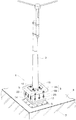
図1に示すように、本発明の設置物固定具の一実施形態品(以後、単に固定台1という)を使用して、屋上のコンクリート床やベランダ等の建築物(取付下地2の一例)の上に、アンテナの支柱等の設置物3を固定してある状況を示している。
Hereinafter, embodiments of the present invention will be described with reference to FIGS.
As shown in FIG. 1, an embodiment of the installation fixture according to the present invention (hereinafter simply referred to as a fixing base 1) is used to construct a building such as a rooftop concrete floor or a veranda (an example of the mounting base 2). The situation where the
前記コンクリート床2の上には、防水シート6が敷設してある。
当該実施形態においては、コンクリート床2の全域に防水シート6が敷設してある状態で、その上に、金属製の当該固定台1を設置して、設置物3を固定台1に固定してある例を示している。従って、固定台1を設置した後、その周囲に、図6に示すように、防水シート6と固定台1の外周部にわたる状態に立上り防水層7を設置し、その上端部をバンド29で縛ると共に、シール剤30を塗布して雨水の浸入を防止し、固定台設置部分から下方への漏水防止を図っている。
コンクリート床2における固定台設置箇所には、予め、アンカーボルト8が設置してあり、このアンカーボルト8に固定台1が固定されている。
A
In the embodiment, in a state where the
An
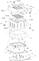
前記固定台1は、上部に開口部4を形成する有底筒状の下地側支持部材5と、開口部4を上から覆う蓋部材13と、その蓋部材13に連結する設置物支持部材9とから構成してある。
前記下地側支持部材5の有底筒状の底部には、取付下地2に取り付けたアンカーボルト8を挿通する第1挿通孔11を形成して、取付下地2に対する固定部12を構成してある。
尚、下地側支持部材5の底部には、径方向外方に延設する鍔状設置部14を形成してあり、この鍔状設置部14にもボルト挿通孔15を周方向に複数設けて、取付下地2に固定できるように構成してある。
The
A
In addition, a hook-
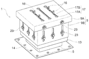
前記開口部4の外周側に形成される前記下地側支持部材5の第1周壁部18に対し、その外側を囲繞する第2周壁部19を蓋部材13に設け、第1周壁部18と第2周壁部19とに互いに連結自在な第1連結部20を設け、第2周壁部19に対する第2連結部21を備えた設置物支持部材9を設け、設置物3に対する連結用ボルト16の頭部を係入自在なボルト挿通部17を設置物支持部材9に設け、蓋部材13の天面を、ボルト挿通部17の下側でそのボルト挿通部17を通して侵入する雨水を受けて蓋部材13の横外方に排出する雨水誘導ガイド部に構成してある。
A second
図2、図6に示すように、前記第1周壁部18に設ける第1連結部20は、第1周壁部18にチャンネル材25を溶接一体化し、そのチャンネル材25にボルト挿通孔15を複数個形成して凹部内にナットNを内装して構成してある。
前記第2周壁部19に設ける第1連結部20は、第1周壁部18に設けた第1連結部20夫々に対応した位置に、複数のボルト挿通孔15を設けてあるだけである。従って、連結ボルトを第1連結部20のボルト挿通孔15に挿通させて、チャンネル材25のナットNに螺合させることで、下地側支持部材5に蓋部材13を、連結一体化が可能になるように構成してある。
As shown in FIGS. 2 and 6, the first connecting
The first connecting
第2連結部21を上下方向の長孔26にして、設置物支持部材9の第3周壁部27に形成し、設置物支持部材9を下地側支持部材5に対して上下位置変更自在に連結する上下位置変更機構に形成してある。
尚、第1連結部20と第2連結部21とは、図2、図6に示すように、連結ボルトとナットNとで共締めして、下地側支持部材5に蓋部材13と設置物支持部材9とが同時に連結固定されるように構成してある
The second connecting
As shown in FIGS. 2 and 6, the first connecting
前記設置物支持部材9を、ボルト挿通部17を備えた設置物連結部材9Aと第3周壁部27に第2連結部21を備えた支持連結部材9Bとに分割構成すると共に、設置物連結部材9Aと支持連結部材9Bとを互いに連結自在にする第3連結部28を設け、設置物連結部材9Aを支持連結部材9Bに対して横方向に変位自在にする横変位機構を第3連結部28に設けてある。つまり、第3連結部28は、第3周壁部27の上部に形成した横方向に長い横長孔31と、設置物連結部材9Aの第4周壁部32に形成した丸孔33から形成し、その横長孔31と丸孔33に同時に連結ボルトを挿通させて締め付けることで、横変位機構を構成してある。
The installation
図2〜図6に示すように、前記設置物連結部材9Aの天面に形成したボルト挿通部17は、ボルト頭を挿通自在な大径孔部17Aと、ボルトの軸部より少し大きい幅でボルト頭を抜け止めする長孔状の係止孔部17Bとが一連に形成され、設置物連結部材9Aの天面の裏側に、ボルト頭を回り止めする樋状の係止部材34を溶接により一体的に取り付けてある。つまり、ボルト頭を大径孔部17Aに上方から挿通させた後に、係止孔部17Bの長手方向に移動させることで、ボルトは抜け止めされ、しかも、ボルト頭は、係止部材34により回り止めされるように構成してある。
また、前記樋状の係止部材34は、設置物連結部材9Aの天面の裏側に一体に溶接してあることにより、天面におけるボルト挿通部17周辺部の補強の役目を担い、ボルト挿通部17に係止した連結用ボルト16に、引抜力が働いた時に、天面が変形しながらボルト挿通部17の係止孔部17Bの幅が拡大して連結用ボルト17が抜けてしまうのを防止できる。
As shown in FIGS. 2 to 6, the
Further, the hook-shaped locking
〔別実施形態〕
以下に他の実施の形態を説明する。
〈1〉 前記設置物3は、実施形態のように、アンテナの支柱以外に、太陽電池パネルの支持フレームであったり、その他の装置であっても良い。
〈2〉 設置物支持部材9は、設置物連結部材9Aと支持連結部材9Bとに分割構成してある場合以外に、それらが一体形成してあるものであっても良い。
〈3〉 前記設置物支持部材9の天面に設けたボルト挿通部17は、長孔状以外に、スリット状であっても良く、また、連結用ボルト16の取り付け位置の調整が不要であるならば、単にボルト頭が係止する大きさの丸孔形状であっても良い。
〈4〉 第1連結部20と第2連結部21とは、連結用ボルト16とナットNとで共締めして、下地側支持部材5に蓋部材13と設置物支持部材9とが同時に連結固定されるように構成したが、第2周壁部19に対し第1連結部20とは異なる位置に、第2連結部21が位置して、別々の連結用ボルト16とナットNで個別に連結するように形成しても良い。この場合、設置物支持部材9に設ける第2連結部21を、丸孔にすると共に、第2周壁部19に設ける第2連結部21を上下長孔に形成して、上下変更機構を構成するようにすることも考えられる。
〈5〉 前記下地側支持部材5は、第1連結部20を構成するのに、図7に示すように、第1周壁部18の上端縁部に、金属製の帯状の補強帯板35を全周にわたって一体に溶接し、その補強帯板35にナットNを溶接により取り付けて第1連結部20を構成してあっても良い。また、図8(a)、(b)に示すように、ナットNを上方から嵌入することで回り止めして収容するナット収納箱部材36を溶接着けしてあっても良い。この場合、ナット収納箱部材36は、板金製で金属板を折り曲げて形成し、底板部36Aを第1周壁部18より遠ざかるほど低くなるように傾斜させると共に、下部コーナー部に隙間37を形成し(図8(a))、上方のナット出入用開口部より例え雨水が浸入したとしても、その隙間37から外方へ排出されるように構成してある。また、ナット収納箱部材36内にナットNを挿入させると、傾斜した底板部36Aに受けられたナットNは、ボルト挿通孔20Aに近接する(図8(a))ように案内される。しかし、この状態では、ボルト挿通孔20Aの中心軸心と、ナットNの中心軸心は合わず、ボルト挿通孔20Aから連結ボルト23によって、ナットNが第1周壁部18に近接するように押し込まれることによって、挿入する双方の軸心が一致するように(図8(c))設定してある。
〈6〉 前記ボルト挿通部17を長孔に形成すると共に、その長孔の長手方向を変更自在にする長孔方向変更機構を、設置物支持部材9に設けるために、図9〜図11に示すように、下地側支持部材5、蓋部材13、設置物支持部材9のすべてを、上下に軸心を沿わせた円筒形状にして、上下軸心周りに回転自在に形成しても良い。つまり、第1周壁部18、第2周壁部19、第3周壁部27、第4周壁部32を円筒形状に形成して、図11(a)、(b)、(c)のように、支持連結部材9Bに対して設置物連結部材9Aを360度相対回転させてボルト挿通部17の長手方向を変更することで、連結用ボルト16の取り付け位置を横方向の2次元方向に変位して自在に調整できるように構成してある。尚、横変位機構の横長孔31は、上下に2段に併設して、上記相対回転させて連結ボルトを挿通させる際に、使い分けできるように構成してある。
〈7〉 前記係止部材34は、図12に示すように、連結用ボルト16の頭の回り止めを行うのに、内側にボルト頭に接当する棒状部材を溶接により一体取付してあっても良い。
尚、上述のように、図面との対照を便利にするために符号を記したが、該記入により本発明は添付図面の構成に限定されるものではない。また、本発明の要旨を逸脱しない範囲において、種々なる態様で実施し得ることは勿論である。
[Another embodiment]
Other embodiments will be described below.
<1> The
<2> The installation
<3> The
<4> The first connecting
<5> The base-
<6> In order to provide the installation
<7> As shown in FIG. 12, the locking
In addition, as mentioned above, although the code | symbol was written in order to make contrast with drawing convenient, this invention is not limited to the structure of an accompanying drawing by this entry. In addition, it goes without saying that the present invention can be carried out in various modes without departing from the gist of the present invention.
2 取付下地
3 設置物
4 開口部
5 下地側支持部材
9 設置物支持部材
9A 設置物連結部材
9B 支持連結部材
12 固定部
13 蓋部材
16 連結用ボルト
17 ボルト挿通部
18 第1周壁部
19 第2周壁部
20 第1連結部
21 第2連結部
28 第3連結部
DESCRIPTION OF
Claims (3)
前記開口部を上方から覆う蓋部材を設け、
前記開口部の外周側に形成される前記下地側支持部材の上下方向に沿った第1周壁部に対し、その外側を囲繞する上下方向に沿った第2周壁部を前記蓋部材に設け、
前記第1周壁部の外側にナットの保持部を設けると共に、
前記第2周壁部に前記ナットに対して螺合自在なボルトのボルト挿通孔を設けて、前記ナットと前記ボルトの連結によって前記第1周壁部と前記第2周壁部とが互いに連結する第1連結部を形成し、
前記蓋部材とは別部材で前記蓋部材の上側に配置する設置物支持部材に、下地側支持部材に対する第2連結部を備え、
設置物に対する連結用ボルトの頭部を係入自在なボルト挿通部を前記設置物支持部材に設け、
前記ボルト挿通部の下側でそのボルト挿通部を通して侵入する雨水を前記蓋部材の上面で受けて前記蓋部材の横外方に排出する雨水誘導ガイド部を、前記蓋部材に構成してある設置物固定具。 A bottomed cylindrical base-side support member that forms an opening at the top is equipped with a fixing part to the mounting base at the bottom.
Providing a lid member for covering the opening from above;
For the first peripheral wall portion along the vertical direction of the base support member formed on the outer peripheral side of the opening, a second peripheral wall portion along the vertical direction surrounding the outside is provided in the lid member,
While providing a nut holding portion outside the first peripheral wall portion,
A bolt insertion hole for a bolt that can be screwed to the nut is provided in the second peripheral wall portion, and the first peripheral wall portion and the second peripheral wall portion are connected to each other by connecting the nut and the bolt. Forming a connecting part,
The installation object supporting member arranged on the upper side of the lid member, which is a member different from the lid member, includes a second connecting portion for the base side support member,
A bolt insertion part is provided on the installation object support member to freely engage the head of the connection bolt to the installation object,
An installation in which the lid member is configured with a rainwater guiding guide portion that receives rainwater entering through the bolt insertion portion below the bolt insertion portion at the upper surface of the lid member and discharges the rainwater laterally outward of the lid member. A fixture.
前記設置物連結部材を前記支持連結部材に対して横方向に変位自在にする横変位機構を前記第3連結部に設けてある請求項1または2に記載の設置物固定具。 The installation object support member is divided into an installation object connection member including the bolt insertion part and a support connection member including the second connection part, and the installation object connection member and the support connection member are mutually connected. A third connecting part is provided for connection;
The installation fixture according to claim 1 or 2, wherein a lateral displacement mechanism that allows the installation connection member to be displaced laterally with respect to the support connection member is provided in the third connection portion.
Priority Applications (1)
| Application Number | Priority Date | Filing Date | Title |
|---|---|---|---|
| JP2011256993A JP5859290B2 (en) | 2011-11-25 | 2011-11-25 | Installation fixture |
Applications Claiming Priority (1)
| Application Number | Priority Date | Filing Date | Title |
|---|---|---|---|
| JP2011256993A JP5859290B2 (en) | 2011-11-25 | 2011-11-25 | Installation fixture |
Related Child Applications (1)
| Application Number | Title | Priority Date | Filing Date |
|---|---|---|---|
| JP2014238178A Division JP5955928B2 (en) | 2014-11-25 | 2014-11-25 | Installation fixture |
Publications (3)
| Publication Number | Publication Date |
|---|---|
| JP2013112932A JP2013112932A (en) | 2013-06-10 |
| JP2013112932A5 JP2013112932A5 (en) | 2015-01-15 |
| JP5859290B2 true JP5859290B2 (en) | 2016-02-10 |
Family
ID=48708740
Family Applications (1)
| Application Number | Title | Priority Date | Filing Date |
|---|---|---|---|
| JP2011256993A Active JP5859290B2 (en) | 2011-11-25 | 2011-11-25 | Installation fixture |
Country Status (1)
| Country | Link |
|---|---|
| JP (1) | JP5859290B2 (en) |
Families Citing this family (2)
| Publication number | Priority date | Publication date | Assignee | Title |
|---|---|---|---|---|
| JP6223797B2 (en) * | 2013-11-29 | 2017-11-01 | 株式会社ベルテック | Other fixtures |
| JP6688558B2 (en) * | 2015-01-28 | 2020-04-28 | 株式会社ベルテック | Others fixture |
Family Cites Families (3)
| Publication number | Priority date | Publication date | Assignee | Title |
|---|---|---|---|---|
| JP2555103Y2 (en) * | 1992-07-10 | 1997-11-19 | 三菱自動車工業株式会社 | Truck cab structure |
| JP4597199B2 (en) * | 2008-01-18 | 2010-12-15 | コスモシステム株式会社 | Foundation frame for installation of equipment and installation method of the foundation frame |
| JP5189538B2 (en) * | 2009-03-27 | 2013-04-24 | ヤンマー株式会社 | Package storage type engine generator rooftop exhaust pipe penetration waterproof structure |
-
2011
- 2011-11-25 JP JP2011256993A patent/JP5859290B2/en active Active
Also Published As
| Publication number | Publication date |
|---|---|
| JP2013112932A (en) | 2013-06-10 |
Similar Documents
| Publication | Publication Date | Title |
|---|---|---|
| JP5620164B2 (en) | Other fixtures | |
| JP5752389B2 (en) | Other fixtures | |
| JP5859290B2 (en) | Installation fixture | |
| JP5955928B2 (en) | Installation fixture | |
| JP6203908B2 (en) | Installation fixture | |
| JP2013112932A5 (en) | ||
| JP6014919B2 (en) | Other fixtures | |
| JP4461819B2 (en) | Waterproof structure for penetrating members such as struts that penetrate the waterproof sheet | |
| JP5190961B2 (en) | Connection structure of a gantry having a drainage part, and connection structure of a gantry for laying solar cell modules | |
| JP5859291B2 (en) | Installation fixture | |
| JP5955929B2 (en) | Installation fixture | |
| JP5738343B2 (en) | Other fixtures | |
| JP6334949B2 (en) | Tile-type support fixture for articles installed on tile roofs | |
| JP6688558B2 (en) | Others fixture | |
| JP5956018B2 (en) | Other fixtures | |
| JP5956019B2 (en) | Other fixtures | |
| JP2015014183A (en) | Other-body fixture | |
| JP5694036B2 (en) | Hardware for installing outdoor installations | |
| JP5948383B2 (en) | Other fixtures | |
| JP6072848B2 (en) | Other fixtures | |
| JP6505989B2 (en) | Pedestal with roof | |
| JP2016113025A (en) | Installation structure of vehicle door glass | |
| JP2017025699A (en) | Other object fixture | |
| JP2550475B2 (en) | Human foramen | |
| JP5427091B2 (en) | Other fixtures |
Legal Events
| Date | Code | Title | Description |
|---|---|---|---|
| A521 | Written amendment |
Free format text: JAPANESE INTERMEDIATE CODE: A523 Effective date: 20141125 |
|
| A621 | Written request for application examination |
Free format text: JAPANESE INTERMEDIATE CODE: A621 Effective date: 20141125 |
|
| A977 | Report on retrieval |
Free format text: JAPANESE INTERMEDIATE CODE: A971007 Effective date: 20150528 |
|
| A131 | Notification of reasons for refusal |
Free format text: JAPANESE INTERMEDIATE CODE: A131 Effective date: 20150623 |
|
| A521 | Written amendment |
Free format text: JAPANESE INTERMEDIATE CODE: A523 Effective date: 20150817 |
|
| TRDD | Decision of grant or rejection written | ||
| A01 | Written decision to grant a patent or to grant a registration (utility model) |
Free format text: JAPANESE INTERMEDIATE CODE: A01 Effective date: 20151201 |
|
| A61 | First payment of annual fees (during grant procedure) |
Free format text: JAPANESE INTERMEDIATE CODE: A61 Effective date: 20151216 |
|
| R150 | Certificate of patent or registration of utility model |
Ref document number: 5859290 Country of ref document: JP Free format text: JAPANESE INTERMEDIATE CODE: R150 |
|
| R250 | Receipt of annual fees |
Free format text: JAPANESE INTERMEDIATE CODE: R250 |
|
| R250 | Receipt of annual fees |
Free format text: JAPANESE INTERMEDIATE CODE: R250 |