JP5856657B2 - Cooker - Google Patents

Cooker Download PDF

Info

Publication number
JP5856657B2
JP5856657B2 JP2014146485A JP2014146485A JP5856657B2 JP 5856657 B2 JP5856657 B2 JP 5856657B2 JP 2014146485 A JP2014146485 A JP 2014146485A JP 2014146485 A JP2014146485 A JP 2014146485A JP 5856657 B2 JP5856657 B2 JP 5856657B2
Authority
JP
Japan
Prior art keywords
steam
chamber
heating
heater
steam generator
Prior art date
Legal status (The legal status is an assumption and is not a legal conclusion. Google has not performed a legal analysis and makes no representation as to the accuracy of the status listed.)
Active
Application number
JP2014146485A
Other languages
Japanese (ja)
Other versions
JP2014196901A (en
JP2014196901A5 (en
Inventor
正浩 西島
正浩 西島
内海 崇
崇 内海
Current Assignee (The listed assignees may be inaccurate. Google has not performed a legal analysis and makes no representation or warranty as to the accuracy of the list.)
Sharp Corp
Original Assignee
Sharp Corp
Priority date (The priority date is an assumption and is not a legal conclusion. Google has not performed a legal analysis and makes no representation as to the accuracy of the date listed.)
Filing date
Publication date
Application filed by Sharp Corp filed Critical Sharp Corp
Priority to JP2014146485A priority Critical patent/JP5856657B2/en
Publication of JP2014196901A publication Critical patent/JP2014196901A/en
Publication of JP2014196901A5 publication Critical patent/JP2014196901A5/ja
Application granted granted Critical
Publication of JP5856657B2 publication Critical patent/JP5856657B2/en
Active legal-status Critical Current
Anticipated expiration legal-status Critical

Links

Images

Description

本発明は蒸気にて食品を加熱調理する加熱調理器に関する。   The present invention relates to a cooking device for cooking food with steam.

食品を加熱調理する場合、栄養価の高い食品を摂取することができるように、調理中における食品の細胞破壊を抑制し、食品に含まれる栄養素の流出を防ぐことが望ましい。オーブン(加熱調理器)を用いて、食品を加熱調理した場合、高温の雰囲気の中で食品の中心部まで適度な温度で熱が伝導し、食品から栄養素が流出することを防ぐことができる。   When cooking food, it is desirable to suppress cell destruction of the food during cooking and prevent the outflow of nutrients contained in the food so that food with high nutritional value can be ingested. When food is cooked using an oven (heating cooker), heat can be conducted at an appropriate temperature to the center of the food in a high-temperature atmosphere, and nutrients can be prevented from flowing out of the food.

近年では、健康志向の高まりを受け、食品の栄養素の流出を防ぐと共に脂肪分を排除することができる蒸気を用いた加熱調理器が提案されている(例えば特許文献1参照)。特許文献1に記載の加熱調理器は、食品を加熱するための加熱室と、給水された水をヒータによって蒸発させる蒸気発生器とを備えており、蒸気発生器から高温の蒸気を加熱室に供給する。加熱室に供給された蒸気は、食品に触れ、蒸気から大量の熱が食品に伝導する。その結果、食品からは脂肪分が効率よく排除される。   In recent years, there has been proposed a cooking device using steam capable of preventing the outflow of food nutrients and excluding fat, in response to an increase in health consciousness (see, for example, Patent Document 1). The heating cooker described in Patent Document 1 includes a heating chamber for heating food and a steam generator for evaporating supplied water by a heater, and high-temperature steam from the steam generator to the heating chamber. Supply. The steam supplied to the heating chamber touches the food, and a large amount of heat is conducted from the steam to the food. As a result, fat is efficiently removed from food.

特開2006−84059号公報JP 2006-84059 A

最近では、脂肪分の排除を促進すべく、蒸気の温度を更に上昇させることが求められており、この要求に応えるために、ヒータの温度を更に上昇させることが考えられる。しかし、蒸気発生器の耐熱温度には限界があり、また安全性の観点からもヒータの温度を過剰に上昇させることは好ましくない。またヒータの消費電力が嵩むという問題もある。   Recently, in order to promote the elimination of fat, it has been required to further increase the temperature of the steam. In order to meet this requirement, it is conceivable to further increase the temperature of the heater. However, the heat resistance temperature of the steam generator is limited, and it is not preferable to raise the temperature of the heater excessively from the viewpoint of safety. There is also a problem that the power consumption of the heater increases.

本発明は斯かる事情に鑑みてなされたものであり、ヒータなどの熱源の温度を過剰に上昇させることなく、蒸気を安全に効率よく加熱することができる加熱調理器を提供することを目的とする。   The present invention has been made in view of such circumstances, and an object thereof is to provide a cooking device capable of safely and efficiently heating steam without excessively increasing the temperature of a heat source such as a heater. To do.

本発明に係る加熱調理器は、食品を収容して加熱する加熱室と、該加熱室に蒸気を供給する蒸気発生器と、該蒸気発生器に給水する給水手段とを備える加熱調理器において、前記蒸気発生器は、複数のヒータを備え、前記複数のヒータのうち少なくとも一つは、前記給水手段から供給される位置に最も近い蒸発ヒータであり前記複数のヒータのうち少なくとも他の一つは、前記蒸気発生器内における蒸気の通流経路にて前記蒸発ヒータよりも下流側に配置してあり、蒸気を加熱するための加熱ヒータであり、前記蒸気発生器の内面において、前記加熱ヒータと前記蒸発ヒータとが配置される位置に跨った放熱フィンを有することを特徴とする。
The cooking device according to the present invention is a cooking device comprising a heating chamber for containing and heating food, a steam generator for supplying steam to the heating chamber, and a water supply means for supplying water to the steam generator. the steam generator is provided with a plurality of heaters, at least one of the plurality of heaters is the closest to the evaporation heater in a position that will be supplied from the water supply means, at least another one of the plurality of heaters Is a heater disposed downstream of the evaporation heater in the steam flow path in the steam generator, for heating the steam, and on the inner surface of the steam generator, the heater And a radiation fin straddling the position where the evaporation heater is disposed .

本発明に係る加熱調理器は、前記蒸気発生器は、前記蒸発ヒータと前記加熱ヒータとが鉛直方向に略平行に配置されることを特徴とする。
In the heating cooker according to the present invention, the steam generator is characterized in that the evaporating heater and the heating heater are arranged substantially parallel to a vertical direction .

本発明に係る加熱調理器にあっては、放熱フィンに沿って蒸気が通流する間に、蒸気に対して連続的に熱が供給される。
In the cooking device according to the present invention, heat is continuously supplied to the steam while the steam flows along the radiation fins.

実施の形態1に係る加熱調理器を略示する右側面断面図である。FIG. 3 is a right side cross-sectional view schematically showing the heating cooker according to the first embodiment. 加熱調理器を略示する正面断面図である。It is front sectional drawing which shows a heating cooker schematically. 蒸気発生器の構成を示す正面図である。It is a front view which shows the structure of a steam generator. 蒸気発生器の構成を示す背面図である。It is a rear view which shows the structure of a steam generator. 蒸気発生器の構成を示す縦断正面図である。It is a vertical front view which shows the structure of a steam generator. 図3のVI−VI線断面図である。It is the VI-VI sectional view taken on the line of FIG. 図3のVII−VII線断面図である。It is the VII-VII sectional view taken on the line of FIG. 蓋体の構成を示す内側斜視図である。It is an inner side perspective view which shows the structure of a cover body. 実施の形態2に係る加熱調理器における蒸気発生器の略示正面図である。It is a schematic front view of the steam generator in the heating cooker according to the second embodiment. 実施の形態3に係る加熱調理器における蒸気発生器の略示正面図である。FIG. 10 is a schematic front view of a steam generator in a heating cooker according to Embodiment 3. 実施の形態4に係る加熱調理器における蒸気発生器を略示する斜視図である。FIG. 10 is a perspective view schematically showing a steam generator in a heating cooker according to a fourth embodiment. 実施の形態5に係る加熱調理器における蒸気発生器を略示する正面図である。FIG. 10 is a front view schematically showing a steam generator in a heating cooker according to a fifth embodiment. 図12のXIII−XIII線断面図である。It is the XIII-XIII sectional view taken on the line of FIG. 実施の形態6に係る加熱調理器における蒸気発生器を略示する正面図である。FIG. 10 is a front view schematically showing a steam generator in a heating cooker according to a sixth embodiment. 図14のXV―XV線断面図である。It is the XV-XV sectional view taken on the line of FIG.

(実施の形態1)
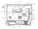
以下本発明を実施の形態1に係る加熱調理器を示す図面に基づいて詳述する。図1は加熱調理器を略示する右側面断面図、図2は加熱調理器を略示する正面断面図である。
(Embodiment 1)
Hereinafter, the present invention will be described in detail with reference to the drawings illustrating a cooking device according to a first embodiment. FIG. 1 is a right side sectional view schematically showing a cooking device, and FIG. 2 is a front sectional view schematically showing the cooking device.

図において1は直方体の筐体であり、該筐体1に食品を加熱するための加熱室11が収容してある。加熱室11には、二つのトレイ(受皿)60、60が上下に並んで収容されており、該トレイ60上に載置網61が設けてある。載置網61には食品100が載置される。   In the figure, reference numeral 1 denotes a rectangular parallelepiped housing, in which a heating chamber 11 for heating food is accommodated. In the heating chamber 11, two trays (receiving trays) 60 and 60 are accommodated side by side, and a placement net 61 is provided on the tray 60. The food 100 is placed on the placement net 61.

筐体1及び加熱室11の間であって、加熱室11の下方及び右側方には外気流入ダクト70が形成されている。筐体1の下部には吸込口71が開設してあり、外気流入ダクト70は吸込口71に接続している。筐体1の後面部には図示しない開口が設けてあり、外気流入ダクト70は該開口に接続している。   An outside air inflow duct 70 is formed between the housing 1 and the heating chamber 11 and below and on the right side of the heating chamber 11. A suction port 71 is opened at the lower portion of the housing 1, and the outside air inflow duct 70 is connected to the suction port 71. An opening (not shown) is provided in the rear surface portion of the housing 1, and the outside air inflow duct 70 is connected to the opening.

外気流入ダクト70内には、冷却ファン23、電装部75及びマグネトロン13が配してある。冷却ファン23は、外気流入ダクト70内に吸込口71を介して外気を取り込み、発熱する電装部75及びマグネトロン13を冷却する。外気流入ダクト70内に取り込まれた空気は、前記開口から排出される。   In the outside air inflow duct 70, the cooling fan 23, the electrical component 75, and the magnetron 13 are arranged. The cooling fan 23 takes outside air into the outside air inflow duct 70 via the suction port 71 and cools the electrical component 75 and the magnetron 13 that generate heat. The air taken into the outside air inflow duct 70 is discharged from the opening.

電装部75は加熱調理器の各部を駆動する駆動回路及び該駆動回路を制御する制御部を有している。なお制御部は、マイクロ波によって食品を加熱するマイクロ波加熱モードにおいて、図示しない操作部からの入力信号に基づいて必要な加熱制御を行う。マグネトロン13は、加熱調理用の電磁波を発生し、導波管76を介して加熱室11にマイクロ波を供給する。なお導波管76には、回転アンテナ14及び該回転アンテナ14を駆動するモータ24が設けてあり、回転アンテナ14によって、マイクロ波は加熱室11に均一に供給される。   The electrical unit 75 has a drive circuit that drives each part of the cooking device and a control unit that controls the drive circuit. The control unit performs necessary heating control based on an input signal from an operation unit (not shown) in a microwave heating mode in which food is heated by microwaves. The magnetron 13 generates electromagnetic waves for cooking and supplies microwaves to the heating chamber 11 via the waveguide 76. The waveguide 76 is provided with the rotating antenna 14 and the motor 24 that drives the rotating antenna 14, and the microwave is uniformly supplied to the heating chamber 11 by the rotating antenna 14.

前記外気流入ダクト70内であって、加熱室11の右側方に吸気ダクト18が設けてある。筐体1の右側面部に開口が設けてあり、該開口に吸気ダクト18は接続している。前記開口には吸気ファン25が設けてある。加熱室11の右側面部11a(壁体)に給気口55が設けてあり、該給気口55に吸気ダクト18は接続している。吸気ファン25の駆動によって、外気が吸気ダクト18に取り込まれ、給気口55から加熱室11に供給される。   An intake duct 18 is provided in the outside air inflow duct 70 on the right side of the heating chamber 11. An opening is provided on the right side surface of the housing 1, and the intake duct 18 is connected to the opening. An intake fan 25 is provided in the opening. An air supply port 55 is provided in the right side surface portion 11 a (wall body) of the heating chamber 11, and the intake duct 18 is connected to the air supply port 55. By driving the intake fan 25, outside air is taken into the intake duct 18 and supplied to the heating chamber 11 from the air supply port 55.

加熱室11の右側方後寄りに、排気ダクト19が設けてある。排気ダクト19は上方に延出しており、延出端部に排気口19aが設けてある。加熱室11の右側面部11aの後部に加熱室11内の空気を取り入れるための取入口56が開設してあり、該取入口56に排気ダクト19が接続している。加熱室11内の空気は、取入口56を介して排気ダクト19に取り込まれ、排気口19aから外部に排出される。   An exhaust duct 19 is provided on the right rear side of the heating chamber 11. The exhaust duct 19 extends upward, and an exhaust port 19a is provided at the extended end. An intake 56 for taking in the air in the heating chamber 11 is opened at the rear of the right side surface portion 11 a of the heating chamber 11, and the exhaust duct 19 is connected to the intake 56. The air in the heating chamber 11 is taken into the exhaust duct 19 through the intake port 56 and is discharged to the outside through the exhaust port 19a.

前記加熱室11の後面部の中央部分に吸気口51が開設してあり、加熱室11の後面部において、吸気口51の周囲に複数の噴出口52が開設してある。加熱室11の後側には循環ダクト50が設けてあり、該循環ダクト50は、吸気口51及び噴出口52に接続されている。循環ダクト50内には、循環ヒータ22及び循環ファン53が設けてある。該循環ファン53には、ファンモータ54が連結しており、ファンモータ54の駆動によって、加熱室11内の空気が吸気口51から吸引され、循環ヒータ22にて加熱された後に噴出口52から加熱室11に戻る。   An intake port 51 is opened at the center of the rear surface portion of the heating chamber 11, and a plurality of jet ports 52 are opened around the intake port 51 in the rear surface portion of the heating chamber 11. A circulation duct 50 is provided on the rear side of the heating chamber 11, and the circulation duct 50 is connected to the intake port 51 and the jet port 52. A circulation heater 22 and a circulation fan 53 are provided in the circulation duct 50. A fan motor 54 is connected to the circulation fan 53. When the fan motor 54 is driven, air in the heating chamber 11 is sucked from the intake port 51 and heated by the circulation heater 22, and then from the outlet 52. Return to the heating chamber 11.

加熱室11の天面に、加熱室11内の温度を検出する温度センサ21が設けてある。前記循環ヒータ22は、温度センサ21にて検出された温度に基づいて制御され、後述する蒸気発生器Aから加熱室11内に供給された蒸気を所望の温度に維持する。   A temperature sensor 21 that detects the temperature in the heating chamber 11 is provided on the top surface of the heating chamber 11. The circulating heater 22 is controlled based on the temperature detected by the temperature sensor 21, and maintains the steam supplied from the steam generator A, which will be described later, into the heating chamber 11 at a desired temperature.

加熱室11の右側面部11aの上部中央には、複数の吹出口26、26、・・・、26が上下二列に並設してある。該吹出口26に対向させて、蒸気発生器Aが右側面部11aの外側に固定してある。蒸気発生器Aにて発生した蒸気は、上下二列の吹出口26から吹出される。上側の吹出口26から吹出された蒸気は、主に上側のトレイ60に載置された食品に接触し、下側の吹出口26から吹出された蒸気は、主に下側のトレイ60に載置された食品に接触する。   A plurality of outlets 26, 26,..., 26 are arranged in two upper and lower rows in the upper center of the right side surface portion 11 a of the heating chamber 11. The steam generator A is fixed to the outside of the right side surface portion 11a so as to face the air outlet 26. The steam generated in the steam generator A is blown out from the upper and lower two rows of outlets 26. The steam blown out from the upper outlet 26 mainly contacts the food placed on the upper tray 60, and the steam blown out from the lower outlet 26 mainly puts on the lower tray 60. Contact the placed food.

蒸気発生器Aの右側に着脱自在の給水タンク15が配してあり、該給水タンク15は給水ポンプ17を介して給水管16(給水手段)に接続している。給水管16は蒸気発生器Aに接続してあり、給水ポンプ17の駆動によって、給水タンク15から蒸気発生器Aに水が供給される。   A detachable water supply tank 15 is arranged on the right side of the steam generator A, and the water supply tank 15 is connected to a water supply pipe 16 (water supply means) via a water supply pump 17. The feed water pipe 16 is connected to the steam generator A, and water is supplied from the feed water tank 15 to the steam generator A by driving the feed water pump 17.

蒸気発生器Aは、前後に長く、前部分が半円状に湾曲したU字形のヒータ2を備えている。蒸気発生器Aは、給水タンク15から供給された水をヒータ2によって蒸発させる。発生した蒸気は吹出口26を介して加熱室11に供給され、食品100を加熱調理する。   The steam generator A includes a U-shaped heater 2 that is long in the front-rear direction and has a front portion curved in a semicircular shape. The steam generator A evaporates the water supplied from the water supply tank 15 by the heater 2. The generated steam is supplied to the heating chamber 11 through the air outlet 26, and the food 100 is cooked.

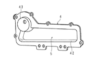
図3は蒸気発生器の構成を示す正面図、図4は蒸気発生器の構成を示す背面図、図5は蒸気発生器の構成を示す縦断正面図、図6は図3のVI−VI線断面図、図7は図3のVII−VII線断面図、図8は蓋体の構成を示す内側斜視図である。   3 is a front view showing the configuration of the steam generator, FIG. 4 is a rear view showing the configuration of the steam generator, FIG. 5 is a longitudinal front view showing the configuration of the steam generator, and FIG. 6 is a VI-VI line in FIG. FIG. 7 is a sectional view taken along the line VII-VII in FIG. 3, and FIG. 8 is an inner perspective view showing the structure of the lid.

図3及び図4に示すように、蒸気発生器Aは、導出口31及びヒータ2を有する板状の水加熱体3と、給水管16が接続された給水口41を有し、水加熱体3の一面側に取付けられた横長の蓋体4とを備える。   As shown in FIGS. 3 and 4, the steam generator A has a plate-shaped water heating body 3 having the outlet 31 and the heater 2, and a water supply port 41 to which the water supply pipe 16 is connected. 3 and a horizontally long lid 4 attached to one surface side.

水加熱体3はアルミニウム及びアルミニウム合金等の熱伝導率の高い金属性材料からなり、横方向に長く正面視略矩形をなす板部3a(壁部)を備えている。該板部3aの一面の上部に横長の第1凹所32が設けてある。また図5に示すように、板部3aの他面に、横長の第2凹所33と該第2凹所33の外周りから突出する環状壁34とが設けてある。   The water heater 3 is made of a metallic material having high thermal conductivity such as aluminum and aluminum alloy, and includes a plate portion 3a (wall portion) that is long in the lateral direction and has a substantially rectangular shape in front view. A horizontally long first recess 32 is provided on the upper surface of the plate portion 3a. As shown in FIG. 5, a laterally long second recess 33 and an annular wall 34 protruding from the outer periphery of the second recess 33 are provided on the other surface of the plate portion 3 a.

図6に示すように、前記蓋体4は第1凹所32に対向しており、蓋体4及び第1凹所32によって横長の蒸発室5が形成されている。一方、図5及び図7に示すように、板部3aの他面側には、第2凹所33を含む板部3aの他面及び環状壁34によって横長のバッファ室6が形成されている。バッファ室6は板部3aを介して蒸発室5に隣接しており、蒸発室5の熱がバッファ室6に伝導する。   As shown in FIG. 6, the lid 4 faces the first recess 32, and the horizontally long evaporation chamber 5 is formed by the lid 4 and the first recess 32. On the other hand, as shown in FIGS. 5 and 7, a horizontally long buffer chamber 6 is formed on the other surface side of the plate portion 3 a by the other surface of the plate portion 3 a including the second recess 33 and the annular wall 34. . The buffer chamber 6 is adjacent to the evaporation chamber 5 through the plate portion 3 a, and the heat of the evaporation chamber 5 is conducted to the buffer chamber 6.

板部3aに、加熱室6の前後方向に沿ってヒータ2が埋設されており、ヒータ2は、上側に位置する熱源2aと下側に位置する熱源2bとを備える。熱源2aと熱源2bとは、上下方向に並んでいる。熱源2aは、蒸発室5に近接しており、熱源2bは蒸発室5から下側に離れている。また熱源2a及び熱源2bはバッファ室6に近接している。すなわち、熱源2aは主に水を蒸発させる目的で使用され、熱源2bは主に蒸気を加熱させる目的で使用される。   A heater 2 is embedded in the plate portion 3a along the front-rear direction of the heating chamber 6. The heater 2 includes a heat source 2a located on the upper side and a heat source 2b located on the lower side. The heat source 2a and the heat source 2b are arranged in the vertical direction. The heat source 2a is close to the evaporation chamber 5, and the heat source 2b is separated from the evaporation chamber 5 downward. The heat source 2 a and the heat source 2 b are close to the buffer chamber 6. That is, the heat source 2a is mainly used for the purpose of evaporating water, and the heat source 2b is mainly used for the purpose of heating steam.

なお熱源2bは吹出口26の近傍に位置する。そのため吹出口26近傍にて蒸気の温度が上昇し、高温に加熱された蒸気が直ちに加熱室11に供給される。また蒸発室5から離れた位置に配置することによって、熱源2bの熱は主にバッファ室6に伝導し、バッファ室6の温度が迅速に上昇する。   The heat source 2b is located in the vicinity of the air outlet 26. Therefore, the temperature of the steam rises in the vicinity of the outlet 26, and the steam heated to a high temperature is immediately supplied to the heating chamber 11. Further, by disposing at a position away from the evaporation chamber 5, the heat of the heat source 2b is mainly conducted to the buffer chamber 6, and the temperature of the buffer chamber 6 rises rapidly.

バッファ室6と蒸発室5との間にヒータ2が配設してあり、ヒータ2の熱が両室に供給され、蒸発及び蒸気の再加熱のための熱効率が向上する。また板部3aに略平行な面内に熱源2aと熱源2bとが位置しており、蒸気発生容器Aの薄型化及び小型化が促進され、筐体1と加熱室11との狭い空間に蒸気発生容器Aを配設し易くなる。   The heater 2 is disposed between the buffer chamber 6 and the evaporation chamber 5, and the heat of the heater 2 is supplied to both chambers, so that the thermal efficiency for evaporation and vapor reheating is improved. In addition, the heat source 2a and the heat source 2b are located in a plane substantially parallel to the plate portion 3a, and the steam generation container A is promoted to be thinner and smaller, and steam is formed in a narrow space between the housing 1 and the heating chamber 11. It becomes easy to arrange the generating container A.

板部3aの上部には、導出口31が開設してある。給水口41から蒸発室5に水が供給された場合、熱源2aによって水は蒸発室5内で蒸発し、発生した蒸気は導出口31を介してバッファ室6に導出され、貯留される。   A lead-out port 31 is opened at the top of the plate portion 3a. When water is supplied from the water supply port 41 to the evaporation chamber 5, the water is evaporated in the evaporation chamber 5 by the heat source 2 a, and the generated steam is led out to the buffer chamber 6 through the outlet port 31 and stored.

なお導出口31は吹出口26よりも上側に位置する。導出口31から供給された蒸気はバッファ室6内に充満し、下側に位置する吹出口26から吹き出される。そのため多量の蒸気がバッファ室6内で加熱され、高温の蒸気が途切れることなく加熱室11に供給される。   The outlet 31 is located above the outlet 26. The steam supplied from the outlet 31 fills the buffer chamber 6 and is blown out from the outlet 26 located on the lower side. Therefore, a large amount of steam is heated in the buffer chamber 6, and high-temperature steam is supplied to the heating chamber 11 without interruption.

板部3aには、板部3aの横方向一側部から上方へ先細状に延出し、給水口41に対向する延出部3bが一体に設けてある。前記第1凹所32は、延出部3bに亘って形成されている。なお第1凹所32は、蓋体4から離れる方向に窪んでいる。   The plate portion 3a is integrally provided with an extension portion 3b that extends upward from one lateral side of the plate portion 3a in a tapered manner and faces the water supply port 41. The first recess 32 is formed across the extension 3b. The first recess 32 is recessed in a direction away from the lid 4.

U字形の前記ヒータ2は、熱源2aを上側にし、熱源2bを下側にして、板部3aの下部にダイキャスト成形によって埋設されている。ヒータ2の湾曲部は、延出部3bの下側に位置している。板部3aの上部には、上側に突出した二つの取付片35、35が横方向に離隔して一体に設けられている。取付片35には、取付軸27が嵌入される嵌入孔35aが開設してある。   The U-shaped heater 2 is embedded in the lower portion of the plate portion 3a by die casting with the heat source 2a on the upper side and the heat source 2b on the lower side. The curved portion of the heater 2 is located below the extension portion 3b. Two attachment pieces 35, 35 projecting upward are integrally provided on the upper portion of the plate portion 3 a so as to be separated from each other in the lateral direction. The attachment piece 35 has an insertion hole 35a into which the attachment shaft 27 is inserted.

図5及び図6に示すように、水加熱体3において、延出部3bの下側であって、U字形をなすヒータ2の湾曲部と対向する位置に温度センサ7が設けられている。該温度センサ7は、温度変化に応じて電気抵抗値が変化する素子(サーミスタ)を備え、水加熱体3の温度を監視して蒸発室5内で空焚されたり、蒸発室5内が温度不足になったりするのを防ぐために使用される。また、板部3aにおける一面の周縁部には環状溝3cが設けてあり、該環状溝3cに封止部材36が嵌入保持され、蓋体4との間の隙間が封止されている。   As shown in FIGS. 5 and 6, in the water heater 3, a temperature sensor 7 is provided at a position below the extending portion 3 b and facing the curved portion of the U-shaped heater 2. The temperature sensor 7 includes an element (thermistor) whose electric resistance value changes according to a temperature change, monitors the temperature of the water heater 3 and is emptied in the evaporation chamber 5, or the temperature in the evaporation chamber 5 is a temperature. Used to prevent shortages. An annular groove 3c is provided on the peripheral edge of one surface of the plate portion 3a. A sealing member 36 is fitted and held in the annular groove 3c, and a gap between the lid body 4 is sealed.

第1凹所32は、延出部3bに亘って窪む深底部32aと、該深底部32aの下縁に湾曲角部を経て連なる浅底部32bとを有する。深底部32aの下面及び浅底部32bと対向する箇所に蒸発用の熱源2aが配されている。   The first recess 32 has a deep bottom portion 32a that is recessed over the extending portion 3b, and a shallow bottom portion 32b that continues to the lower edge of the deep bottom portion 32a via a curved corner. A heat source 2a for evaporation is disposed at a position facing the lower surface of the deep bottom portion 32a and the shallow bottom portion 32b.

蓋体4は、横方向に長く正面視略矩形をなす板部4aを備えている。該板部4aの下部には、水加熱体3から離れる方向に突出した外向凸部4bが設けてある。該外向凸部4bの内面は、横長の第3凹所42となっている。第1凹所32及び第3凹所42は、蒸発用の熱源2aに沿った横方向に長い蒸発室5を形成している。   The lid 4 includes a plate portion 4a that is long in the lateral direction and has a substantially rectangular shape in front view. An outward convex portion 4b protruding in a direction away from the water heater 3 is provided at the lower portion of the plate portion 4a. The inner surface of the outwardly projecting portion 4b is a horizontally long third recess 42. The first recess 32 and the third recess 42 form a long evaporation chamber 5 in the lateral direction along the heat source 2a for evaporation.

図4及び図6に示すように、板部4aの横方向に沿った一側部は、上方へ先細状に延出された延出部4cを有している。該延出部4cの周縁を除く中央部に、外面が円形の凹所となり、先端が延出部3bの一面と対向する内向凸部43が形成されている。該内向凸部43の中央部に前記給水口41が開設してあり、該給水口41に給水管16の先端部が嵌入保持されている。蓋体4の周縁部は、複数の雄螺子によって水加熱体3の周縁部に取外しを可能に取付けられている。   As shown in FIG.4 and FIG.6, the one side part along the horizontal direction of the board part 4a has the extension part 4c extended in the taper shape upwards. An inward convex portion 43 is formed in the central portion excluding the peripheral edge of the extending portion 4c, and the outer surface is a circular recess, and the tip is opposed to one surface of the extending portion 3b. The water supply port 41 is opened at the center of the inward convex portion 43, and the distal end portion of the water supply pipe 16 is fitted and held in the water supply port 41. The peripheral part of the cover body 4 is attached to the peripheral part of the water heating body 3 by a plurality of male screws so as to be removable.

給水管16の先端部は、給水口41から延出部3bに向けて延出しており、延出部3bの一面と僅少間隔で対向している。そのため給水管16から蒸発室5へ給水される水は、延出部3bの一面を伝って流下する。   The front end portion of the water supply pipe 16 extends from the water supply port 41 toward the extension portion 3b, and faces one surface of the extension portion 3b with a slight interval. Therefore, the water supplied from the water supply pipe 16 to the evaporation chamber 5 flows down along one surface of the extending portion 3b.

第3凹所42の下面、換言すると蒸発室5の下面は導出口31側が高く、給水口41側が低くなるように傾斜しており、給水された水が蒸発室5の下面に流下しても、導出口31から離隔した側で蒸発させることができる。   The lower surface of the third recess 42, in other words, the lower surface of the evaporation chamber 5 is inclined so that the outlet port 31 side is higher and the water supply port 41 side is lower, and even if the supplied water flows down to the lower surface of the evaporation chamber 5 , And can be evaporated on the side away from the outlet 31.

導出口31は板部3aの上部を貫通しており、横方向に長い長円形をなす。また導出口31は給水口41から横方向へ離隔した位置であって、上下方向において給水口41と略同じ位置に配置してある。   The outlet 31 penetrates the upper part of the plate portion 3a and forms an oval shape that is long in the lateral direction. In addition, the outlet 31 is a position separated from the water supply port 41 in the horizontal direction, and is arranged at substantially the same position as the water supply port 41 in the vertical direction.

前述したように蒸発室5にて発生した蒸気は、導出口31を通流してバッファ室6に導出される。図5及び図7に示すように、バッファ室6は、第2凹所33を含む板部3aの他面及び環状壁34によって形成されている。バッファ室6の中央部には、横方向に長く、導出口31から板部3aの厚さ方向と交差する方向(板部3aの他面に沿う方向)へ蒸気を誘導する板状の誘導壁37が設けられている。誘導壁37は、板部3aの他面から加熱室11に向けて突出している。誘導壁37に沿ってバッファ室6の蒸気が蛇行して長時間通流し、加熱室11から大量の熱が蒸気に供給される。また誘導壁37が長く設計された場合、蒸気に供給される熱量が増加する。   As described above, the vapor generated in the evaporation chamber 5 flows into the buffer chamber 6 through the outlet 31. As shown in FIGS. 5 and 7, the buffer chamber 6 is formed by the other surface of the plate portion 3 a including the second recess 33 and the annular wall 34. The central part of the buffer chamber 6 is a plate-like guide wall that is long in the lateral direction and guides steam from the outlet 31 to the direction intersecting the thickness direction of the plate part 3a (the direction along the other surface of the plate part 3a). 37 is provided. The induction wall 37 protrudes toward the heating chamber 11 from the other surface of the plate portion 3a. The steam in the buffer chamber 6 meanders along the guide wall 37 and flows for a long time, and a large amount of heat is supplied from the heating chamber 11 to the steam. In addition, when the guide wall 37 is designed to be long, the amount of heat supplied to the steam increases.

誘導壁37は、上下方向において熱源2a、2bの間に位置している。熱源2aは、誘導壁37の上面と環状壁34との間に位置し、熱源2bは、誘導壁37の下面と環状壁34との間に位置している。また熱源2a、2bは、誘導壁37に沿って横方向に延出している。そのため誘導壁37及び環状壁34によって形成された蒸気通路を移動している間に、バッファ室6の蒸気に対して熱源2a、2bから連続的に熱が供給される。   The induction wall 37 is located between the heat sources 2a and 2b in the vertical direction. The heat source 2 a is located between the upper surface of the induction wall 37 and the annular wall 34, and the heat source 2 b is located between the lower surface of the induction wall 37 and the annular wall 34. The heat sources 2 a and 2 b extend in the lateral direction along the guide wall 37. Therefore, heat is continuously supplied from the heat sources 2 a and 2 b to the steam in the buffer chamber 6 while moving in the steam passage formed by the guide wall 37 and the annular wall 34.

図5にて示すように、誘導壁37における導出口31側の端部が下方へ屈曲して、環状壁34の下壁部内面に接触している。誘導壁37の下方へ屈曲した部分と環状壁34との間に溜水部3dが形成されている。誘導壁37における導出口31と反対側の端部には、上向きに突出した凸部37aが設けてある。誘導壁37の上面に溜る水は、凸部37aを乗り越えて移動することが難しくなり、溜水部3dへ流下し易くなる。   As shown in FIG. 5, the end of the guide wall 37 on the outlet 31 side is bent downward and is in contact with the inner surface of the lower wall of the annular wall 34. A reservoir 3d is formed between a portion bent downward of the guide wall 37 and the annular wall 34. A convex portion 37 a protruding upward is provided at the end of the guide wall 37 opposite to the outlet 31. It is difficult for the water accumulated on the upper surface of the guide wall 37 to move over the convex portion 37a and to flow down to the water reservoir 3d.

溜水部3dには、第2の温度センサ8が設けられている。該温度センサ8は、温度変化に応じて電気抵抗値が変化する素子(サーミスタ)を備え、温度変化に基づいて溜水部3d内の水位を監視する。所定量の水が溜水部3dに貯留したとき、温度センサ8はオン動作し、前記バッファ室6への水溢れが検知される。なお温度センサ8がオン動作した場合、制御部はヒータ2の駆動を制御し、例えばヒータ2を加熱させる。   A second temperature sensor 8 is provided in the reservoir 3d. The temperature sensor 8 includes an element (thermistor) whose electric resistance value changes according to a temperature change, and monitors the water level in the water reservoir 3d based on the temperature change. When a predetermined amount of water is stored in the reservoir 3d, the temperature sensor 8 is turned on, and overflow of the buffer chamber 6 is detected. When the temperature sensor 8 is turned on, the control unit controls the driving of the heater 2 and heats the heater 2, for example.

前記誘導壁37と前記環状壁34の間における縦断面積(蒸気の通流方向に直交する断面の面積)は、導出口31の開口面積よりも広い。そのため導出口31からバッファ室6に導出された蒸気の圧力は低下し、溜水部3dにて突沸が発生し難くなる。   A vertical cross-sectional area between the guide wall 37 and the annular wall 34 (area of a cross section perpendicular to the flow direction of steam) is larger than the opening area of the outlet 31. Therefore, the pressure of the steam led out from the outlet 31 to the buffer chamber 6 is reduced, and bumping is less likely to occur in the reservoir 3d.

バッファ室6において、誘導壁37よりも下側は前記吹出口26に臨んでいる。導出口31から板部3aの厚さ方向へ吐出された蒸気は、誘導壁37の上側を、図3における左方向に移動し、凸部37aを回り込んで誘導壁37の下側を右側に移動し、吹出口26から加熱室11に吹き出される。   In the buffer chamber 6, the lower side of the guide wall 37 faces the air outlet 26. The steam discharged from the outlet 31 in the thickness direction of the plate portion 3a moves to the left in FIG. 3 on the upper side of the guide wall 37, wraps around the convex portion 37a and the lower side of the guide wall 37 to the right side. It moves and is blown out from the blower outlet 26 to the heating chamber 11.

誘導壁37と環状壁34との間における縦断面積は、複数の吹出口26の総開口面積よりも広くなっており、蒸気の流速は、吹出口26付近において上昇する。そのため、蒸気はバッファ室6内を円滑に流動し、バッファ室6内の圧力上昇が抑制される。   The longitudinal cross-sectional area between the guide wall 37 and the annular wall 34 is larger than the total opening area of the plurality of outlets 26, and the flow velocity of the steam rises in the vicinity of the outlets 26. Therefore, the steam flows smoothly in the buffer chamber 6 and the pressure increase in the buffer chamber 6 is suppressed.

また導出口31と吹出口26とが吹出方向に対向する場合に比べて、導出口31から吹出口26に至る蒸気の通流経路が長くなり、蒸気がバッファ室6内を通流する間に、加熱室11の熱によって蒸気が加熱される。また導出口31から吹出口26まで蒸気が直線的に移動することを防止する。   Compared with the case where the outlet 31 and the outlet 26 are opposed to each other in the outlet direction, the flow path of the steam from the outlet 31 to the outlet 26 becomes longer, and the steam passes through the buffer chamber 6. The steam is heated by the heat of the heating chamber 11. Further, the steam is prevented from moving linearly from the outlet 31 to the outlet 26.

図7に示すように、誘導壁37よりも下側において、板部3aの他面に、第2凹所33よりも深く窪んだ横長溝状の凹部3eが形成されている。そのためバッファ室6の容積が増加し、より大量の蒸気がバッファ室6に貯留され、加熱効率が向上する。   As shown in FIG. 7, on the other side of the plate portion 3 a below the guide wall 37, a horizontally elongated groove-shaped recess 3 e that is deeper than the second recess 33 is formed. For this reason, the volume of the buffer chamber 6 is increased, and a larger amount of steam is stored in the buffer chamber 6 to improve the heating efficiency.

バッファ室6における誘導壁37の左右と、誘導壁37と環状壁34の下壁部との間には、板部3aの他面から突出した筒状の放熱部3fが板部3aと一体に設けられている。放熱部3fを設けることによって、水加熱体3における蒸気の接触面積が増加する。   Between the left and right of the guide wall 37 in the buffer chamber 6 and between the lower wall portion of the guide wall 37 and the annular wall 34, a cylindrical heat radiating portion 3f protruding from the other surface of the plate portion 3a is integrated with the plate portion 3a. Is provided. By providing the heat radiating part 3f, the contact area of the steam in the water heater 3 increases.

図3及び図7に示すように、環状壁34の先端部には加熱室11の右側面部11aと接触する環状の封止部材38が嵌合保持されている。該封止部材38は、環状壁34の内側に突出しており、環状壁34に沿う枠状の密着部38aを備えている。該密着部38aの基端部における厚さ寸法は、密着部38aの突出端部における厚さ寸法よりも短い。そのため、密着部38aは基端部を支点にして撓みやすくなっており、蒸気圧によって加熱室11側に押し当てられる。   As shown in FIGS. 3 and 7, an annular sealing member 38 that is in contact with the right side surface portion 11 a of the heating chamber 11 is fitted and held at the tip of the annular wall 34. The sealing member 38 protrudes inside the annular wall 34 and includes a frame-shaped close contact portion 38 a along the annular wall 34. The thickness dimension at the base end portion of the contact portion 38a is shorter than the thickness dimension at the protruding end portion of the contact portion 38a. Therefore, the contact portion 38a is easily bent with the base end portion as a fulcrum, and is pressed against the heating chamber 11 side by the vapor pressure.

また前記誘導壁37の先端には右側面部11aと接触する封止部材39が嵌合保持されている。封止部材39によって、誘導壁37との右側面部11aとの間を蒸気が通流することを防ぎ、また導出口31から吹出口26に直線的に蒸気が移動することを防止して、加熱室11の熱をバッファ室6に貯留した蒸気に充分に伝導させる。   A sealing member 39 that contacts the right side surface portion 11a is fitted and held at the tip of the guide wall 37. The sealing member 39 prevents the steam from flowing between the guide wall 37 and the right side surface portion 11a, and prevents the steam from moving linearly from the outlet 31 to the outlet 26. The heat of the chamber 11 is sufficiently conducted to the vapor stored in the buffer chamber 6.

蒸気発生器Aを加熱室11の右側面部11aに取り付ける場合、図4及び図7に示すように、蒸気発生器Aの嵌入孔35a、35aに取付軸27、27を嵌込み、取付軸27、27の先部にナット28、28を螺合させる。蒸気発生器Aは、取付軸27、27によって容易に位置決めされ、吹出口26に対する位置が適正となるように右側面部11aに取付けられる。また封止部材38、39が右側面部11aに接触し、バッファ室6が右側面部11aにて閉鎖され、密室状態となる。またバッファ室6内に、加熱室11内の熱が右側面部11aを介して伝導する。すなわち、バッファ室6内の蒸気が、加熱室11内の熱によって再加熱される。またバッファ室6は加熱室11及び蒸発室5に挟まれており、バッファ室6内の温度は高温に保たれる。   When attaching the steam generator A to the right side surface portion 11a of the heating chamber 11, as shown in FIGS. 4 and 7, the attachment shafts 27, 27 are fitted into the fitting holes 35a, 35a of the steam generator A, and the attachment shaft 27, The nuts 28 and 28 are screwed onto the tip of 27. The steam generator A is easily positioned by the mounting shafts 27 and 27, and is attached to the right side surface portion 11a so that the position with respect to the air outlet 26 is appropriate. Further, the sealing members 38 and 39 are brought into contact with the right side surface portion 11a, and the buffer chamber 6 is closed at the right side surface portion 11a to be in a closed chamber state. Further, the heat in the heating chamber 11 is conducted into the buffer chamber 6 through the right side surface portion 11a. That is, the steam in the buffer chamber 6 is reheated by the heat in the heating chamber 11. Further, the buffer chamber 6 is sandwiched between the heating chamber 11 and the evaporation chamber 5, and the temperature in the buffer chamber 6 is kept high.

なお吹出口26は、上下に並んだトレイ60、60に対応させて上下二列に並設してあるが、トレイ60が三つ以上加熱室11に収容されている場合、トレイ60に対応させて吹出口26も三列以上並設される。   The air outlets 26 are arranged in two upper and lower rows so as to correspond to the upper and lower trays 60, 60. However, when three or more trays 60 are accommodated in the heating chamber 11, the air outlet 26 is made to correspond to the tray 60. The air outlets 26 are also arranged in three or more rows.

実施の形態1に係る加熱調理器にあっては、加熱室11にバッファ室6が隣接しており、加熱室11の熱がバッファ室6に伝導する。そのため蒸発室5にて発生した蒸気は、バッファ室6にて再加熱され、ヒータ2の温度を過剰に上昇させることなく、安全に蒸気を加熱することができ、また蒸気を再加熱させるための消費電力を抑制することができる。また蒸気は、バッファ室6を経由して加熱室11に吹出されるので、バッファ室6の設計を変更することによって、蒸気の圧力を適切に調整することができる。   In the heating cooker according to the first embodiment, the buffer chamber 6 is adjacent to the heating chamber 11, and the heat of the heating chamber 11 is conducted to the buffer chamber 6. Therefore, the steam generated in the evaporation chamber 5 is reheated in the buffer chamber 6, so that the steam can be safely heated without excessively increasing the temperature of the heater 2, and for reheating the steam. Power consumption can be suppressed. Further, since the steam is blown out to the heating chamber 11 via the buffer chamber 6, the steam pressure can be appropriately adjusted by changing the design of the buffer chamber 6.

また、蒸発室5にバッファ室6が隣接しており、蒸発室5の熱がバッファ室6に伝導する。そのため蒸気を発生させるための熱が蒸気の再加熱に利用され、エネルギー効率が向上する。   Further, the buffer chamber 6 is adjacent to the evaporation chamber 5, and the heat of the evaporation chamber 5 is conducted to the buffer chamber 6. Therefore, heat for generating steam is used for reheating the steam, and energy efficiency is improved.

また、前記バッファ室6は、蒸発室5と加熱室11との間に位置しているので、蒸発室5及び加熱室11の熱がバッファ室に伝導する。そのため、両室の熱が蒸気の再加熱に利用され、蒸気の再加熱に関するエネルギー効率を飛躍的に向上させることができる。また両室に挟まれることで、バッファ室6内の温度を高温に維持することができる。   Further, since the buffer chamber 6 is located between the evaporation chamber 5 and the heating chamber 11, the heat of the evaporation chamber 5 and the heating chamber 11 is conducted to the buffer chamber. Therefore, the heat of both chambers is used for steam reheating, and the energy efficiency related to steam reheating can be dramatically improved. Moreover, the temperature in the buffer chamber 6 can be maintained at a high temperature by being sandwiched between the two chambers.

また、バッファ室6と蒸発室5との間にヒータ2が配設してあり、ヒータ2の熱が両室に供給され、蒸発及び蒸気の再加熱のための熱効率を向上させることができる。また蒸気発生容器Aの小型化を促進することができる。   Moreover, the heater 2 is arrange | positioned between the buffer chamber 6 and the evaporation chamber 5, The heat of the heater 2 is supplied to both chambers, and the thermal efficiency for evaporation and reheating of a vapor | steam can be improved. Moreover, size reduction of the steam generation container A can be promoted.

なお実施の形態1に係る加熱調理器は、加熱室11の右側面部11aはバッファ室6の壁部を兼用しているが、右側面部11aに対向して接触するバッファ室6の対向壁部を設けてもよい。この場合、加熱室11の熱が右側面部11a及び対向壁部を伝導し、バッファ室6内の蒸気が加熱される。   In the heating cooker according to the first embodiment, the right side surface portion 11a of the heating chamber 11 also serves as the wall portion of the buffer chamber 6, but the opposing wall portion of the buffer chamber 6 that is in contact with the right side surface portion 11a. It may be provided. In this case, the heat in the heating chamber 11 is conducted through the right side surface portion 11a and the opposing wall portion, and the vapor in the buffer chamber 6 is heated.

また誘導壁37は、バッファ室6内にて横方向に延出しているが、バッファ室6の天面又は底面から縦方向に延出していても良い。   The guide wall 37 extends in the horizontal direction in the buffer chamber 6, but may extend in the vertical direction from the top surface or the bottom surface of the buffer chamber 6.

(実施の形態2)
以下本発明を実施の形態2に係る加熱調理器を示す図面に基づいて詳述する。図9は、実施の形態2に係る加熱調理器における蒸気発生器の略示正面図である。
(Embodiment 2)
Hereinafter, the present invention will be described in detail with reference to the drawings illustrating a cooking device according to a second embodiment. FIG. 9 is a schematic front view of a steam generator in the heating cooker according to the second embodiment.

この蒸気発生器Aは、上下に離隔して対向する二つの誘導壁37c、37dを、バッファ室6の蒸気が蛇行して通流するように配したものである。   In the steam generator A, two guide walls 37c and 37d that are spaced apart from each other and are opposed to each other are arranged so that the steam in the buffer chamber 6 meanders and flows.

上側の誘導壁37cは、導出口31側を下方として傾斜しており、バッファ室6の一側から他側に向けて延出している。誘導壁37cの延出端部とバッファ室6の他側との間には、空間が設けてある。   The upper guide wall 37c is inclined with the outlet 31 side as a lower side, and extends from one side of the buffer chamber 6 to the other side. A space is provided between the extending end of the guide wall 37c and the other side of the buffer chamber 6.

下側の誘導壁37dは、導出口31側を上方として傾斜しており、バッファ室6の他側から一側に向けて延出している。誘導壁37dの延出端部とバッファ室6の一側との間には、空間が設けてある。また下側の誘導壁37dは、吹出口26の上側に位置している。   The lower guide wall 37d is inclined with the outlet 31 side as the upper side, and extends from the other side of the buffer chamber 6 toward one side. A space is provided between the extending end of the guide wall 37d and one side of the buffer chamber 6. Further, the lower guide wall 37d is positioned above the air outlet 26.

誘導壁37cの導出口31側であって、誘導壁37cの上側に溜水部3dが形成されている。また誘導壁37dの導出口31と反対側であって、誘導壁37dの上側に溜水部3dが形成されている。   A reservoir 3d is formed on the guide port 37c side of the guide wall 37c and above the guide wall 37c. Further, a reservoir 3d is formed on the side opposite to the outlet 31 of the guide wall 37d and above the guide wall 37d.

実施の形態2に係る加熱調理器の構成の内、実施の形態1と同様な構成については同じ符号を付し、その詳細な説明を省略する。   Of the configuration of the heating cooker according to the second embodiment, the same components as those of the first embodiment are denoted by the same reference numerals, and detailed description thereof is omitted.

(実施の形態3)
以下本発明を実施の形態3に係る加熱調理器を示す図面に基づいて詳述する。図10は、実施の形態3に係る加熱調理器における蒸気発生器の略示正面図である。
この蒸気発生器Aは、バッファ室6内の蒸気が渦巻状に通流し、導出口31から吹出口26に至るように誘導壁37dを配したものである。
(Embodiment 3)
Hereinafter, the present invention will be described in detail with reference to the drawings illustrating a cooking device according to a third embodiment. FIG. 10 is a schematic front view of a steam generator in the heating cooker according to the third embodiment.
In the steam generator A, the steam in the buffer chamber 6 flows in a spiral shape, and a guide wall 37d is arranged so as to reach from the outlet 31 to the outlet 26.

誘導壁37dは鈎状をなし、バッファ室6の一側から横方向に長い基部6aと、該基部の先端部から下向きに延出した中間部6bと、該中間部6bの下端部から前記基部6aと対向するように、バッファ室6の一側へ向けて延出した先部6cとを有する。基部6aは、導出口31の下側に位置している。吹出口26は、基部6aと先部6cとの間に位置している。また、バッファ室6内の下面に溜水部3dが形成されている。   The guide wall 37d has a bowl shape, a base portion 6a that is long in the lateral direction from one side of the buffer chamber 6, an intermediate portion 6b that extends downward from the distal end portion of the base portion, and the base portion from the lower end portion of the intermediate portion 6b. It has the front part 6c extended toward one side of the buffer chamber 6 so as to oppose 6a. The base 6 a is located below the outlet 31. The blower outlet 26 is located between the base part 6a and the front part 6c. Further, a water reservoir 3d is formed on the lower surface in the buffer chamber 6.

バッファ室6内の蒸気は、導出口31から吹出口26まで渦巻状に通流し、バッファ室内を蒸気が長時間かけて移動するので、加熱室11内の熱が蒸気に確実に伝導する。   The steam in the buffer chamber 6 flows spirally from the outlet 31 to the outlet 26, and the steam moves in the buffer chamber over a long period of time, so that the heat in the heating chamber 11 is reliably conducted to the steam.

実施の形態3に係る加熱調理器の構成の内、実施の形態1又は2と同様な構成については同じ符号を付し、その詳細な説明を省略する。   Among the configurations of the heating cooker according to the third embodiment, the same reference numerals are given to the same configurations as those in the first or second embodiment, and detailed description thereof is omitted.

(実施の形態4)
以下本発明を実施の形態4に係る加熱調理器を示す図面に基づいて詳述する。図11は、加熱調理器における蒸気発生器を略示する斜視図である。なお図11において、封止部材38、39の記載は省略してある。
(Embodiment 4)
Hereinafter, the present invention will be described in detail with reference to the drawings illustrating a cooking device according to a fourth embodiment. FIG. 11 is a perspective view schematically showing a steam generator in a heating cooker. In FIG. 11, the sealing members 38 and 39 are not shown.

この蒸気発生器Aは、導出口31側を下向きとして傾斜した誘導壁37eを備えている。該誘導壁37eの導出口31側部分は、下向きに屈曲し、バッファ室6の下面に接触している。誘導壁37eの導出口31側部分と環状壁34との間に溜水部3dが形成されている。また、水加熱体3の導出口31下側には、溜水部3d内の水位を検出するためのサーミスタが設けられている。   The steam generator A includes a guide wall 37e that is inclined with the outlet 31 side facing downward. A portion of the guide wall 37 e on the outlet 31 side is bent downward and is in contact with the lower surface of the buffer chamber 6. A water reservoir 3d is formed between the outlet wall 31 side portion of the guide wall 37e and the annular wall 34. A thermistor for detecting the water level in the water reservoir 3d is provided below the outlet 31 of the water heater 3.

実施の形態4に係る加熱調理器にあっては、誘導壁37の上部に水が付着したとしても、付着した水は吹出口26から離れる方向に移動するので、吹出口26から水が吹出ることを抑制することができる。   In the heating cooker according to the fourth embodiment, even if water adheres to the upper portion of the guide wall 37, the attached water moves in a direction away from the outlet 26, so that water blows out from the outlet 26. This can be suppressed.

実施の形態4に係る加熱調理器の構成の内、実施の形態1〜3と同様な構成については同じ符号を付し、その詳細な説明を省略する。   Among the configurations of the heating cooker according to the fourth embodiment, the same reference numerals are given to the same configurations as those of the first to third embodiments, and detailed description thereof is omitted.

(実施の形態5)
以下本発明を実施の形態5に係る加熱調理器を示す図面に基づいて詳述する。図12は、加熱調理器における蒸気発生器を略示する正面図、図13は、図12のXIII−XIII線断面図である。
(Embodiment 5)
Hereinafter, the present invention will be described in detail with reference to the drawings illustrating a cooking device according to a fifth embodiment. 12 is a front view schematically showing a steam generator in the heating cooker, and FIG. 13 is a cross-sectional view taken along line XIII-XIII in FIG.

この蒸気発生器Aは、上下に並んだ蒸発室5及びバッファ室6を備えている。蒸気発生器Aは横長矩形の一面が開放された容器を有しており、該容器の開放された一面側は、加熱室11の右側面部11aに対向している。容器の内部には、内部空間を上下に分割する横長の分割壁3hが設けてある。分割壁3hの上側に蒸発室5が形成してあり、分割壁3hの下側にバッファ室6が形成してある。   The steam generator A includes an evaporation chamber 5 and a buffer chamber 6 that are arranged vertically. The steam generator A has a container whose one side of the horizontally long rectangle is opened, and the opened one side of the container faces the right side part 11 a of the heating chamber 11. A horizontally long dividing wall 3h that divides the internal space vertically is provided inside the container. An evaporation chamber 5 is formed above the dividing wall 3h, and a buffer chamber 6 is formed below the dividing wall 3h.

蒸発室5には、給水管16が接続してある。また蒸発室5には、バッファ室6に連通する導出口31が給水管16から離隔して設けてある。バッファ室6には、右側面部11aに対向したバッファ室6の壁部から右側面部11aに突出した誘導壁37fが設けてある。誘導壁37fは、導出口31側から横方向に延出しており、導出口31側を下方として傾斜している。また右側面部11aに対向したバッファ室6の壁部には凹部3eが設けてある。   A water supply pipe 16 is connected to the evaporation chamber 5. The evaporating chamber 5 is provided with a lead-out port 31 communicating with the buffer chamber 6 so as to be separated from the water supply pipe 16. The buffer chamber 6 is provided with a guide wall 37f protruding from the wall portion of the buffer chamber 6 facing the right side surface portion 11a to the right side surface portion 11a. The guide wall 37f extends in the lateral direction from the outlet 31 side and is inclined with the outlet 31 side as the lower side. A recess 3e is provided in the wall of the buffer chamber 6 facing the right side surface 11a.

前記分割壁3hに横長の熱源2aが埋設してあり、バッファ室6の下部に横長の熱源2bが埋設してある。なお吹出口26はバッファ室6に隣接しており、熱源2bは吹出口26の近傍に位置している。熱源2aの熱は蒸発室5及びバッファ室6に伝導し、熱源2bの熱はバッファ室6に伝導する。また加熱室11の熱が蒸発室5及びバッファ室6に伝導する。   A horizontally long heat source 2 a is embedded in the dividing wall 3 h, and a horizontally long heat source 2 b is embedded in the lower portion of the buffer chamber 6. The air outlet 26 is adjacent to the buffer chamber 6, and the heat source 2 b is located in the vicinity of the air outlet 26. The heat of the heat source 2 a is conducted to the evaporation chamber 5 and the buffer chamber 6, and the heat of the heat source 2 b is conducted to the buffer chamber 6. Further, the heat in the heating chamber 11 is conducted to the evaporation chamber 5 and the buffer chamber 6.

実施の形態5に係る加熱調理器にあっては、蒸発室5は加熱室11に隣接しており、加熱室11の熱が蒸発室5に伝導する。そのため加熱室11の熱が、水の蒸発に利用され、蒸発のための熱効率が向上し、また蒸発室5に熱を供給するヒータ2への負担が軽減される。   In the heating cooker according to Embodiment 5, the evaporation chamber 5 is adjacent to the heating chamber 11, and the heat of the heating chamber 11 is conducted to the evaporation chamber 5. Therefore, the heat in the heating chamber 11 is used for water evaporation, the thermal efficiency for evaporation is improved, and the burden on the heater 2 that supplies heat to the evaporation chamber 5 is reduced.

なお実施の形態5に係る加熱調理器にあっては、蒸発室5を上側とし、バッファ室6を下側としているが、蒸発室5及びバッファ室6の位置は上下逆であっても良い。   In the heating cooker according to the fifth embodiment, the evaporation chamber 5 is on the upper side and the buffer chamber 6 is on the lower side, but the positions of the evaporation chamber 5 and the buffer chamber 6 may be upside down.

実施の形態5に係る加熱調理器の構成の内、実施の形態1〜4と同様な構成については同じ符号を付し、その詳細な説明を省略する。   Among the configurations of the heating cooker according to the fifth embodiment, the same reference numerals are given to the same configurations as those of the first to fourth embodiments, and detailed description thereof is omitted.

(実施の形態6)
以下本発明を実施の形態6に係る加熱調理器を示す図面に基づいて詳述する。図14は、加熱調理器における蒸気発生器を略示する正面図、図15は図14のXV―XV線断面図である。
(Embodiment 6)
Hereinafter, the present invention will be described in detail with reference to the drawings showing a cooking device according to a sixth embodiment. 14 is a front view schematically showing a steam generator in the cooking device, and FIG. 15 is a cross-sectional view taken along the line XV-XV in FIG.

この蒸気発生器Aは、左右に並んだ蒸発室5及びバッファ室6を備えている。蒸気発生器Aは横長矩形の一面が開放された容器を有しており、該容器の開放された一面側は、加熱室11の右側面部11aに対向している。容器の内部には、内部空間を左右に分割する上下に延びた分割壁3iが設けてある。図14に示すように、分割壁3iの右側に蒸発室5が形成してあり、分割壁3iの左側にバッファ室6が形成してある。   The steam generator A includes an evaporation chamber 5 and a buffer chamber 6 arranged side by side. The steam generator A has a container whose one side of the horizontally long rectangle is opened, and the opened one side of the container faces the right side part 11 a of the heating chamber 11. Inside the container, there is provided a dividing wall 3i extending vertically to divide the internal space into left and right. As shown in FIG. 14, the evaporation chamber 5 is formed on the right side of the dividing wall 3i, and the buffer chamber 6 is formed on the left side of the dividing wall 3i.

蒸発室5における右側面部11aに対向する壁の上側に給水管16が接続してある。また蒸発室5及びバッファ室6を連通する導出口31が分割壁3iの上側に、給水管16から離隔して設けてある。バッファ室6には、右側面部11aに対向したバッファ室6の壁部から右側面部11aに向けて突出した誘導壁37gが設けてある。誘導壁37gは、右側から左側に延出しており、右側を下方として傾斜している。また右側面部11aに対向したバッファ室6の壁部には凹部3eが設けてある。   A water supply pipe 16 is connected to the upper side of the wall facing the right side surface portion 11 a in the evaporation chamber 5. An outlet 31 for communicating the evaporation chamber 5 and the buffer chamber 6 is provided on the upper side of the dividing wall 3 i so as to be separated from the water supply pipe 16. The buffer chamber 6 is provided with a guide wall 37g protruding from the wall portion of the buffer chamber 6 facing the right side surface portion 11a toward the right side surface portion 11a. The guide wall 37g extends from the right side to the left side, and is inclined with the right side as a lower side. A recess 3e is provided in the wall of the buffer chamber 6 facing the right side surface 11a.

右側面部11aに対向した蒸気発生器Aの壁部に、U字形のヒータ2が埋設してある。ヒータ2は横方向に延びる熱源2a、2bを備え、各熱源2a、2bは上下に並んでいる。蒸発室5において、給水管16から供給された水は壁を伝い、熱源2a、2bから熱が供給される。またバッファ室6において、導出口31から導出された蒸気に、熱源2a、2bから熱が供給される。各熱源2a、2bの熱は、水の蒸発及び蒸気の再加熱に使用される。   A U-shaped heater 2 is embedded in the wall portion of the steam generator A facing the right side surface portion 11a. The heater 2 includes heat sources 2a and 2b extending in the lateral direction, and the heat sources 2a and 2b are arranged vertically. In the evaporation chamber 5, the water supplied from the water supply pipe 16 travels through the wall, and heat is supplied from the heat sources 2a and 2b. In the buffer chamber 6, heat is supplied from the heat sources 2 a and 2 b to the steam led out from the outlet 31. The heat of each heat source 2a, 2b is used for water evaporation and steam reheating.

また加熱室11の熱が蒸発室5及びバッファ室6に伝導する。そのため加熱室11の熱が、水の蒸発に利用され、蒸発のための熱効率が向上し、また蒸発室5に熱を供給するヒータ2への負担が軽減される。   Further, the heat in the heating chamber 11 is conducted to the evaporation chamber 5 and the buffer chamber 6. Therefore, the heat in the heating chamber 11 is used for water evaporation, the thermal efficiency for evaporation is improved, and the burden on the heater 2 that supplies heat to the evaporation chamber 5 is reduced.

なお実施の形態6に係る加熱調理器にあっては、蒸発室5を右側とし、バッファ室6を左側としているが、蒸発室5及びバッファ室6の位置は左右逆であっても良い。   In the cooking device according to the sixth embodiment, the evaporation chamber 5 is on the right side and the buffer chamber 6 is on the left side, but the positions of the evaporation chamber 5 and the buffer chamber 6 may be reversed.

実施の形態6に係る加熱調理器の構成の内、実施の形態1〜5と同様な構成については同じ符号を付し、その詳細な説明を省略する。   Among the configurations of the heating cooker according to the sixth embodiment, the same reference numerals are given to the same configurations as those of the first to fifth embodiments, and detailed description thereof is omitted.

実施の形態1〜6に係る加熱調理器にあっては、蒸発室5及びバッファ室6は隣接しているが、蒸気を加熱室11の熱によって加熱するためには必ずしも隣接している必要はない。例えば蒸発室5をバッファ室6から離して配置し、蒸発室5及びバッファ室6をチューブのような通気路を介して連通させてもよい。この場合においても、蒸発室5から通気路を介してバッファ室6に導出された蒸気は、バッファ室6に隣接する加熱室11から伝導した熱によって、安全に且つ効率よく加熱される。   In the cooking device according to the first to sixth embodiments, the evaporation chamber 5 and the buffer chamber 6 are adjacent to each other. However, in order to heat the steam by the heat of the heating chamber 11, it is not always necessary to be adjacent. Absent. For example, the evaporation chamber 5 may be disposed away from the buffer chamber 6, and the evaporation chamber 5 and the buffer chamber 6 may be communicated with each other through a ventilation path such as a tube. Even in this case, the steam led out from the evaporation chamber 5 to the buffer chamber 6 through the ventilation path is safely and efficiently heated by the heat conducted from the heating chamber 11 adjacent to the buffer chamber 6.

以上説明した実施の形態は本発明の例示であり、本発明は特許請求の範囲の記載に基づいて定められる範囲内において種々変更した形態で実施することができる。   The embodiment described above is an exemplification of the present invention, and the present invention can be implemented in variously modified forms within the scope determined based on the description of the claims.

(付記)以上の本発明の実施の形態に関し、更に以下の事項を開示する。   (Additional remarks) The following matters are further disclosed regarding the embodiment of the present invention described above.

本発明に係る加熱調理器は、食品を収容して加熱する加熱室11と、該加熱室11に蒸気を供給する蒸気発生器Aと、該蒸気発生器Aに給水する給水手段16とを備える加熱調理器において、前記蒸気発生器Aは、前記給水手段16から供給された水を蒸発させるための蒸発ヒータ2aと、前記蒸気発生器A内における蒸気の通流経路にて前記蒸発ヒータ2aよりも下流側に配置してあり、蒸気を加熱するための加熱ヒータ2bとを備え、前記蒸気発生器Aの内側空間における蒸気の通流方向に直交する断面の面積は、加熱ヒータ2b側を蒸発ヒータ2a側よりも狭くしてあることを特徴とする。   The heating cooker according to the present invention includes a heating chamber 11 that accommodates and heats food, a steam generator A that supplies steam to the heating chamber 11, and a water supply means 16 that supplies water to the steam generator A. In the heating cooker, the steam generator A includes an evaporation heater 2a for evaporating the water supplied from the water supply means 16, and the evaporation heater 2a through a steam flow path in the steam generator A. And a heater 2b for heating the steam, the area of the cross section perpendicular to the direction of steam flow in the inner space of the steam generator A evaporates on the heater 2b side. It is narrower than the heater 2a side.

本発明に係る加熱調理器は、前記蒸気発生器Aは、前記蒸発ヒータ2aからの熱が伝導し、前記給水手段16から供給された水を蒸発させる蒸発室5と、該蒸発室5にて発生した蒸気を貯留し、通流させる蒸気通路とを備え、前記蒸気通路から前記加熱室11に蒸気を吹出すようにしてあり、前記蒸気通路と前記蒸発室5とが隣接し、前記蒸発室5にて発生した蒸気を前記蒸気通路へ導出する単一の導出口31を前記蒸発室5の上部に設けてあり、前記蒸気通路は複数回屈曲していることを特徴とする。   In the cooking device according to the present invention, the steam generator A includes an evaporation chamber 5 in which heat from the evaporation heater 2a is conducted and the water supplied from the water supply means 16 is evaporated. A steam passage for storing and flowing the generated steam, and steam is blown out from the steam passage to the heating chamber 11, the steam passage and the evaporation chamber 5 are adjacent to each other, and the evaporation chamber 5, a single outlet 31 for leading the steam generated in 5 to the steam passage is provided above the evaporation chamber 5, and the steam passage is bent a plurality of times.

1 筐体
2 ヒータ
2a、2b 熱源
3 水加熱体
3a 板部(壁部)
3e 凹部
5 蒸発室
6 バッファ室
11 加熱室
11a 右側面(壁体)
16 給水管(給水手段)
26 吹出口
31 導出口
34 環状壁
37 誘導壁
60 トレイ(受皿)
A 蒸気発生容器
DESCRIPTION OF SYMBOLS 1 Housing | casing 2 Heater 2a, 2b Heat source 3 Water heating body 3a Plate part (wall part)
3e Concave portion 5 Evaporating chamber 6 Buffer chamber 11 Heating chamber 11a Right side surface (wall body)
16 Water supply pipe (water supply means)
26 Outlet 31 Outlet 34 Annular Wall 37 Guide Wall 60 Tray (Tray)
A Steam generating container

Claims (2)

食品を収容して加熱する加熱室と、該加熱室に蒸気を供給する蒸気発生器と、該蒸気発生器に給水する給水手段とを備える加熱調理器において、
前記蒸気発生器は、複数のヒータを備え、
前記複数のヒータのうち少なくとも一つは、前記給水手段から供給される位置に最も近い蒸発ヒータであり、
前記複数のヒータのうち少なくとも他の一つは、前記蒸気発生器内における蒸気の通流経路にて前記蒸発ヒータよりも下流側に位置してあり、蒸気を加熱するための加熱ヒータであり、
前記蒸気発生器は、金属材料からなる内面を有し、
前記内面には、前記内面から突出した壁が設けられ、
前記壁は、前記加熱ヒータが配置される位置及び前記蒸発ヒータが配置される位置の両方に跨って接触していることを特徴とする加熱調理器。
In a heating cooker comprising a heating chamber for containing and heating food, a steam generator for supplying steam to the heating chamber, and a water supply means for supplying water to the steam generator,
The steam generator includes a plurality of heaters,
At least one of the plurality of heaters is an evaporation heater closest to a position supplied from the water supply means,
At least another one of the plurality of heaters is a heater for heating the steam, which is located downstream of the evaporation heater in the steam flow path in the steam generator,
The steam generator has an inner surface made of a metal material,
The inner surface is provided with a wall protruding from the inner surface,
The wall heating cooker, characterized in that position and the evaporation heater the heater is disposed in contact across both positions arranged.
前記蒸気発生器は、
前記蒸発ヒータと前記加熱ヒータとが鉛直方向に略平行に配置されることを特徴とする請求項1に記載の加熱調理器。
The steam generator
The cooking device according to claim 1, wherein the evaporating heater and the heating heater are arranged substantially parallel to a vertical direction.
JP2014146485A 2014-07-17 2014-07-17 Cooker Active JP5856657B2 (en)

Priority Applications (1)

Application Number Priority Date Filing Date Title
JP2014146485A JP5856657B2 (en) 2014-07-17 2014-07-17 Cooker

Applications Claiming Priority (1)

Application Number Priority Date Filing Date Title
JP2014146485A JP5856657B2 (en) 2014-07-17 2014-07-17 Cooker

Related Parent Applications (1)

Application Number Title Priority Date Filing Date
JP2013146860A Division JP5588052B2 (en) 2013-07-12 2013-07-12 Cooker

Related Child Applications (2)

Application Number Title Priority Date Filing Date
JP2014216130A Division JP5876916B2 (en) 2014-10-23 2014-10-23 Cooker
JP2014216129A Division JP5755790B2 (en) 2014-10-23 2014-10-23 Cooker

Publications (3)

Publication Number Publication Date
JP2014196901A JP2014196901A (en) 2014-10-16
JP2014196901A5 JP2014196901A5 (en) 2014-12-11
JP5856657B2 true JP5856657B2 (en) 2016-02-10

Family

ID=52357804

Family Applications (1)

Application Number Title Priority Date Filing Date
JP2014146485A Active JP5856657B2 (en) 2014-07-17 2014-07-17 Cooker

Country Status (1)

Country Link
JP (1) JP5856657B2 (en)

Family Cites Families (2)

* Cited by examiner, † Cited by third party
Publication number Priority date Publication date Assignee Title
JP4589819B2 (en) * 2005-06-20 2010-12-01 株式会社東芝 Cooking equipment
JP4435246B2 (en) * 2008-06-26 2010-03-17 シャープ株式会社 Steam generator and cooking device

Also Published As

Publication number Publication date
JP2014196901A (en) 2014-10-16

Similar Documents

Publication Publication Date Title
WO2011136252A1 (en) Cooking device
JP6128341B2 (en) Cooker
JP5525948B2 (en) IH built-in ink heater
JP5070999B2 (en) Steam generator and cooking device using the same
JP5588052B2 (en) Cooker
JP5484507B2 (en) Cooker
JP6468672B1 (en) Cooker
JP5856657B2 (en) Cooker
JP6463280B2 (en) Cooker
JP4555805B2 (en) Cooker
JP5755790B2 (en) Cooker
JP5876916B2 (en) Cooker
JP6503127B2 (en) Cooker
JP4994481B2 (en) Heating cooker
JP2017227440A (en) Heating cooker
JP5501206B2 (en) Cooker
JP4994480B2 (en) Cooker
JP4994487B2 (en) Cooker
JP4994479B2 (en) Cooker
JP6209733B2 (en) Cooker
JP2018033714A (en) Heat cooker

Legal Events

Date Code Title Description
A621 Written request for application examination

Free format text: JAPANESE INTERMEDIATE CODE: A621

Effective date: 20140807

A521 Written amendment

Free format text: JAPANESE INTERMEDIATE CODE: A523

Effective date: 20141023

RD04 Notification of resignation of power of attorney

Free format text: JAPANESE INTERMEDIATE CODE: A7424

Effective date: 20150129

A131 Notification of reasons for refusal

Free format text: JAPANESE INTERMEDIATE CODE: A131

Effective date: 20150526

A977 Report on retrieval

Free format text: JAPANESE INTERMEDIATE CODE: A971007

Effective date: 20150527

A521 Written amendment

Free format text: JAPANESE INTERMEDIATE CODE: A523

Effective date: 20150710

A131 Notification of reasons for refusal

Free format text: JAPANESE INTERMEDIATE CODE: A131

Effective date: 20150915

A521 Written amendment

Free format text: JAPANESE INTERMEDIATE CODE: A523

Effective date: 20151023

TRDD Decision of grant or rejection written
A01 Written decision to grant a patent or to grant a registration (utility model)

Free format text: JAPANESE INTERMEDIATE CODE: A01

Effective date: 20151208

A61 First payment of annual fees (during grant procedure)

Free format text: JAPANESE INTERMEDIATE CODE: A61

Effective date: 20151211

R150 Certificate of patent (=grant) or registration of utility model

Ref document number: 5856657

Country of ref document: JP

Free format text: JAPANESE INTERMEDIATE CODE: R150