JP5070999B2 - Steam generator and cooking device using the same - Google Patents
Steam generator and cooking device using the same Download PDFInfo
- Publication number
- JP5070999B2 JP5070999B2 JP2007226113A JP2007226113A JP5070999B2 JP 5070999 B2 JP5070999 B2 JP 5070999B2 JP 2007226113 A JP2007226113 A JP 2007226113A JP 2007226113 A JP2007226113 A JP 2007226113A JP 5070999 B2 JP5070999 B2 JP 5070999B2
- Authority
- JP
- Japan
- Prior art keywords
- steam
- heating
- water supply
- water
- heating container
- Prior art date
- Legal status (The legal status is an assumption and is not a legal conclusion. Google has not performed a legal analysis and makes no representation as to the accuracy of the status listed.)
- Expired - Fee Related
Links
Images


Description
本発明は、水蒸気を加熱室内の被調理物に供給して調理するオーブンレンジ等の加熱調理器に利用される蒸気発生器およびその蒸気発生器を使用した加熱調理器に関するものである。 The present invention relates to a steam generator used in a heating cooker such as a microwave oven that supplies steam to a cooking object in a heating chamber, and a heating cooker using the steam generator.
従来の加熱調理器は、高周波加熱や電気ヒータによる輻射熱加熱の他に、高温の蒸気を供給する蒸気供給機構を備え、加熱室内に高温蒸気を供給し、その高温蒸気による加熱調理も可能にしたものがある(一般には、スチームオーブンレンジと呼ばれているタイプの調理器が該当する)。
その蒸気供給機構は、加熱調理器本体に着脱可能に装備した貯水タンクの水を、加熱調理器本体に配設した給水路を介して水供給手段により蒸気発生手段に供給し、蒸気発生手段において水を加熱し、発生する蒸気を加熱室内に蒸発拡散させるものである。
In addition to high-frequency heating and radiant heat heating with an electric heater, the conventional cooking device has a steam supply mechanism that supplies high-temperature steam, supplies high-temperature steam into the heating chamber, and enables cooking using the high-temperature steam. There is something (generally a type of cooker called a steam microwave oven).
The steam supply mechanism supplies water from a water storage tank that is detachably attached to the heating cooker body to the steam generation means by a water supply means via a water supply path disposed in the heating cooker body. Water is heated and the generated steam is evaporated and diffused into the heating chamber.
上記の蒸気供給機構は、密閉された蒸気発生室の壁面を電気ヒータ(発熱体)で外部から加熱し、その蒸気発生室の内部に給水パイプ等で水を供給し、供給された水が前記発熱体で高温に加熱された壁面に接触することにより水蒸気となるようにしたものである(例えば、特許文献1参照)。
従来の加熱調理器にあっては、蒸気発生室の壁面に給水パイプの末端に接続された給水口を形成し、この給水口から少量の水を蒸気発生室へ注入するようにしており、給水口から電気ヒータで加熱された蒸気発生面までの間の壁面全体は凹凸のない平面形状となっている。このため、給水口から注入された水は、下方へ重力で自然に流れていく過程で蒸気発生面から熱を受けて蒸気化するが、水と蒸気発生面との接触面積が大きくないので、蒸気発生効率が高くないという問題があった。 In a conventional cooking device, a water supply port connected to the end of the water supply pipe is formed on the wall surface of the steam generation chamber, and a small amount of water is injected from this water supply port into the steam generation chamber. The entire wall surface between the mouth and the steam generation surface heated by the electric heater has a flat shape without irregularities. For this reason, the water injected from the water supply port is vaporized by receiving heat from the steam generation surface in the process of naturally flowing downward by gravity, but the contact area between the water and the steam generation surface is not large, There was a problem that the steam generation efficiency was not high.
さらに、蒸気発生室の壁面温度を迅速に検出し、電気ヒータの通電を的確に制御するという目的で蒸気発生室の外部にはサーミスタ等の温度検出器が取り付けられているが、蒸気発生室の蒸気発生面で効率よく水を加熱し蒸気を発生させることができない場合は、温度検出器が水の蒸気化状態の変化を迅速に捉えられないということであるから、熱源である電気ヒータの正確な温度制御を行えないという懸念もあった。 Furthermore, a temperature detector such as a thermistor is attached to the outside of the steam generation chamber for the purpose of quickly detecting the wall temperature of the steam generation chamber and accurately controlling the energization of the electric heater. If water cannot be efficiently heated and generated on the steam generation surface, it means that the temperature detector cannot quickly detect changes in the vaporization state of the water. There was also a concern that proper temperature control could not be performed.
本発明は上記のような問題を解決するためになされたもので、簡単な構成でありながら効率良く蒸気を発生させることができるようにした蒸気発生器及びそれを用いた加熱調理器を提供することを目的とする。 The present invention has been made to solve the above problems, and provides a steam generator capable of efficiently generating steam with a simple configuration and a cooking device using the steam generator. For the purpose.
本発明に係る蒸気発生器は、密閉された内部空間を有し、かつその空間を形成する少なくとも1壁面に蒸気発生面が設けられた熱伝導性材料から形成された加熱容器と、前記加熱容器の外部からその蒸気発生面に供給された水を加熱し蒸気を発生させる発熱体を有し、前記加熱容器は、内側に前記蒸気発生面を有し、一側面に開口を形成した本体と、この本体の前記開口を閉塞するように前記本体に取り付けられる蓋体とを備え、前記蒸気発生面には蒸気を該加熱容器の外部に噴出する開口が形成され、前記蓋体には給水口が形成されており、該加熱容器は、前記蒸気発生面が垂直又は斜めに傾斜した状態で用いられ、
前記発熱体は、両端に端子部を有する略U字形状をなしており、該端子部が前記加熱容器より上方となるように前記加熱容器に設けられ、前記蒸気発生面には、前記加熱容器の外部から供給された水がそれ自身で下降することを抑制するように突起状の熱交換用フィンを互いに所定間隔を置いて複数個一体に形成されており、該熱交換用フィンは、その最上部と前記蓋体との対向部分に所定の間隙が形成されるような高さを有し、当該間隙が前記蒸気発生面で発生した蒸気の通路になるように形成されている。
A steam generator according to the present invention includes a heating container formed of a heat conductive material having a sealed internal space and a steam generation surface provided on at least one wall surface forming the space, and the heating container A heating element that heats water supplied to the steam generation surface from the outside to generate steam, and the heating container has the steam generation surface on the inside and a body having an opening on one side surface; A lid attached to the main body so as to close the opening of the main body, an opening for ejecting steam to the outside of the heating container is formed on the steam generating surface, and a water supply port is provided on the lid. The heating vessel is used in a state where the steam generation surface is inclined vertically or obliquely,
The heating element has a substantially U shape having terminal portions at both ends, and is provided in the heating container so that the terminal portions are located above the heating container. A plurality of protrusion-like heat exchange fins are integrally formed at a predetermined interval so as to prevent water supplied from the outside of the water from falling by itself. It has a height such that a predetermined gap is formed at a portion where the uppermost part and the lid body are opposed to each other, and the gap is formed so as to be a passage for the steam generated on the steam generation surface.
本発明に係る加熱調理器は、
被加熱物を収容する加熱室と、被加熱物を加熱する加熱手段と、該加熱室に蒸気を供給する蒸気発生手段と、該蒸気発生手段に水を供給する供給手段とを備えた加熱調理器において、
前記蒸気発生手段は、
密閉された内部空間を有し、かつその空間を形成する少なくとも1壁面に垂直または斜めに傾斜した蒸気発生面が設けられた加熱容器と、
該加熱容器の蒸気発生面に向けて前記供給手段からの水を供給する給水パイプと、
前記蒸気発生面を加熱する発熱体と有し、
前記加熱容器は、内側に前記蒸気発生面を有し、一側面に開口を形成した本体と、該本体の前記開口を閉塞するように前記本体に取り付けられる蓋体とを備え、
前記蒸気発生面には蒸気を該加熱容器の外部に噴出する開口が形成され、前記蓋体には前記給水パイプが接続される給水口が形成されており、
前記発熱体は、両端に端子部を有する略U字形状をなしており、該端子部が前記加熱容器より上方となるように前記加熱容器に設けられ、
前記給水パイプから前記蒸気発生面の上に供給される水が、該蒸気発生面を下方に流れる過程で上記発熱体の熱を受けて蒸気化するように構成され、
前記蒸気発生面には、前記給水パイプとの対応部分より少なくとも下方領域に、給水パイプから供給された水がそれ自身で下降することを抑制するように突起状の熱交換用フィンを互いに所定間隔を置いて複数個形成され、
該熱交換用フィンは、その最上部と前記蓋体との対向部分に所定の間隙が形成されるような高さを有し、当該間隙が前記蒸気発生面で発生した蒸気の通路になるように構成されている。
The heating cooker according to the present invention is
Heat cooking comprising a heating chamber for storing an object to be heated, heating means for heating the object to be heated, steam generating means for supplying steam to the heating chamber, and supply means for supplying water to the steam generating means In the vessel
The steam generating means includes
A heating vessel having a sealed internal space and provided with a steam generating surface that is perpendicular or obliquely inclined to at least one wall surface forming the space;
A water supply pipe for supplying water from said supply means toward the steam generating surface of the heating container,
A heating element for heating the vapor generating surface;
The heating container includes a main body having the vapor generation surface on the inside and an opening formed on one side surface, and a lid attached to the main body so as to close the opening of the main body.
The steam generation surface is formed with an opening for ejecting steam to the outside of the heating container, and the lid is formed with a water supply port to which the water supply pipe is connected,
The heating element has a substantially U shape having terminal portions at both ends, and is provided in the heating container such that the terminal portions are above the heating container,
The water supplied onto the steam generating surface from the water supply pipe, configured to vaporize by the heat of the heating body in the course of flowing through the steam generating surface downwardly,
Protruding heat exchange fins are spaced apart from each other by a predetermined distance on the steam generation surface so as to prevent water supplied from the water supply pipe from descending at least in a region below the corresponding portion with the water supply pipe. A plurality is formed by placing
The heat exchanging fin has such a height that a predetermined gap is formed between the uppermost portion and the lid, and the gap serves as a passage for the steam generated on the steam generating surface. It is configured.
本発明の蒸気発生器は、密閉された内部空間を有し、かつその空間を形成する少なくとも1壁面に蒸気発生面が設けられた熱伝導性材料から形成された加熱容器と、前記加熱容器の外部からその蒸気発生面に供給された水を加熱し蒸気を発生させる発熱体とを有し、前記蒸気発生面が垂直または斜めに傾斜した状態になるよう前記加熱容器が設置され、前記蒸気発生面には、前記加熱容器の外部から供給された水がそれ自身で下降することを抑制するように突起状の熱交換用フィンを互いに間隔を置いて複数個一体に形成されているので、熱交換用フィンによって熱交換面積が拡大し、簡単な構成でありながら効率良く蒸気を発生させることができるという効果がある。 The steam generator of the present invention includes a heating container formed of a heat conductive material having a sealed internal space and a steam generation surface provided on at least one wall surface forming the space, and the heating container. A heating element that heats water supplied to the steam generation surface from the outside to generate steam, and the heating container is installed so that the steam generation surface is in a vertical or inclined state, and the steam generation Since the surface is formed with a plurality of protrusion-like heat exchange fins spaced apart from each other so as to prevent water supplied from the outside of the heating container from falling by itself, The heat exchange area is expanded by the replacement fin, and there is an effect that steam can be efficiently generated with a simple configuration.
本発明の加熱調理器は、被加熱物を収容する加熱室と、被加熱物を加熱する加熱手段と、該加熱室に蒸気を供給する蒸気発生手段と、該蒸気発生手段に水を供給する供給手段とを備えた加熱調理器において、前記蒸気発生手段は、密閉された内部空間を有し、かつその空間を形成する少なくとも1壁面に垂直または斜めに傾斜した蒸気発生面が設けられた加熱容器と、この容器の蒸気発生面に向けて前記供給手段からの水を供給する給水パイプと、前記蒸気発生面を加熱する発熱体とを有し、前記給水パイプから蒸気発生面の上に供給される水が、その蒸気発生面を下方に流れる過程で上記発熱体の熱を受けて蒸気化するように構成し、前記蒸気発生面には、前記給水パイプとの対応部分より少なくとも下方領域に、給水パイプから供給された水がそれ自身で下降することを抑制するように突起状の熱交換用フィンを互いに間隔を置いて複数個形成しているので、熱交換用フィンによって熱交換面積が拡大し、簡単な構成でありながら効率良く蒸気を発生させることができるという効果があり、これにより少ない電力消費量で十分な量の蒸気を発生できる効率の良い調理器を提供できるという効果がある。 The heating cooker according to the present invention includes a heating chamber that accommodates an object to be heated, a heating unit that heats the object to be heated, a steam generation unit that supplies steam to the heating chamber, and water that supplies the steam generation unit. In the heating cooker provided with the supply means, the steam generating means has a sealed internal space and is provided with a steam generating surface that is inclined perpendicularly or obliquely to at least one wall surface forming the space. A container, a water supply pipe that supplies water from the supply means toward the steam generation surface of the container, and a heating element that heats the steam generation surface, and is supplied from the water supply pipe onto the steam generation surface The generated water is vaporized by receiving heat from the heating element in the process of flowing down the steam generating surface, and the steam generating surface is at least in a region below the corresponding portion with the water supply pipe. Supplied from the water supply pipe Since a plurality of protruding heat exchange fins are formed at intervals from each other so as to prevent water from descending by itself, the heat exchange area is expanded by the heat exchange fins, and the structure is simple. There is an effect that it is possible to efficiently generate steam, but there is an effect that it is possible to provide an efficient cooker capable of generating a sufficient amount of steam with less power consumption.
実施の形態1.
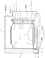
図1は本発明の実施の形態1を示す加熱調理器の左側面からみた側面断面図、図2は同加熱調理器の右側面断面図、図3は同加熱調理器の貯水タンクのつゆ・タンク受け部材への組付状態を示す斜視図、図4は同加熱調理器の貯水タンクの斜視図、図5は蒸気発生手段の加熱容器の分解斜視図、図6は同加熱容器の蓋体を取り外した状態における斜視図、図7は同加熱容器の一側面図、図8は同加熱容器の反対側側面図、図9は同加熱容器の外観を示す側面図、図10は同加熱容器の蓋体を取り外した状態における側面図、図11は同加熱容器の反対側側面図で発熱体の位置を破線で示している。図12は同加熱容器を中央部で縦に切った場合の断面図で一部断面のハッチングは省略している。図13は同加熱容器を温度検出部のある位置で横に切った場合の断面図である。
1 is a side cross-sectional view of the cooking device showing the first embodiment of the present invention as viewed from the left side, FIG. 2 is a cross-sectional view of the right side of the heating cooking device, and FIG. FIG. 4 is a perspective view of a water storage tank of the heating cooker, FIG. 5 is an exploded perspective view of a heating container of the steam generating means, and FIG. 6 is a lid of the heating container. 7 is a side view of the heating container, FIG. 8 is a side view of the heating container opposite to the heating container, FIG. 9 is a side view of the heating container, and FIG. 10 is the heating container. The side view in the state which removed the cover of FIG. 11, FIG. 11 is the opposite side view of the heating container, and has shown the position of the heat generating body with the broken line. FIG. 12 is a cross-sectional view when the heating container is cut vertically at the central portion, and a partial cross-sectional hatching is omitted. FIG. 13 is a cross-sectional view when the heating container is cut horizontally at a position where the temperature detection unit is located.
本発明の実施の形態1の加熱調理器の本体1は、加熱調理する食品等の被加熱物4を収容する加熱室2、その加熱室2の底面に設けられた被加熱物4を載置する載置板3、加熱室2に収容した被加熱物4を加熱する加熱手段である熱風を循環させて加熱する熱風循環手段5やマイクロ波を放射して加熱するマグネトロン6、マイクロ波を導く導波管7、回転アンテナ8及びアンテナモータ9等で構成されている。
A
前記マグネトロン6、導波管7、回転アンテナ8及びアンテナモータ9等についてはすでに公知であるので、詳細な説明は省略するが、これらの構成部品は図示されているように加熱室2と本体1の底面との間の機械室30に配置されている。
Since the magnetron 6, the
オーブン調理に使われる熱風循環手段5は、熱風供給手段を構成するもので、ファンケース5aと、このファンケース5a内の略中央に回転自在に設けられたファン等の送風手段10と、この送風手段10の外周、すなわち空気流の流出側に設けられたヒータ等の加熱手段12と、ファンケース5aの外側に設けられた遮熱板5bと、遮熱板5bの略中央に取り付けられたファンモータ11とで構成され、熱風循環手段5は本体1の背面部に配置されている。
The hot air circulation means 5 used for oven cooking constitutes hot air supply means. The fan case 5a, the air blowing means 10 such as a fan rotatably provided at the substantially center in the fan case 5a, and the air blowing. Heating means 12 such as a heater provided on the outer periphery of the means 10, that is, on the outflow side of the air flow, a heat shield plate 5b provided on the outside of the fan case 5a, and a fan attached to the approximate center of the heat shield plate 5b The hot air circulation means 5 is arranged on the back surface of the
加熱室2の後板2aには、多数のパンチング孔よりなる吸込孔2bと吹出孔2cが設けられており、吸込孔2bは送風手段10の略中心部に対向した位置に設けられ、吹出孔2cは加熱手段12に対向した位置に設けられている。
本体1の前方には被加熱物4を出し入れする開閉自在なドア26が設けられている。
本実施の形態1の加熱調理器は、加熱室2の中央に回転するテーブルがない、いわゆるターンテーブルレス式オーブンレンジと言われるものである。
The
A
The heating cooker according to the first embodiment is a so-called turntableless type microwave oven that does not have a rotating table in the center of the heating chamber 2.
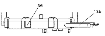
13は蒸気発生手段であり、水が供給される容器13aと、該容器13aを加熱するヒータ13bと、このヒータの通電制御回路(図示せず)に接続されたサーミスタ等の温度検出器31(図12に示す)等から構成されており、これらは熱風循環手段5の横に配置されている。
Reference numeral 13 denotes steam generating means, a temperature detector 31 (such as a thermistor connected to a
容器13aはアルミダイキャスト等のアルミニウム材やステンレス材等の錆び難い金属材料で構成され、定格電力530Wの電気ヒータ13bは容器13aの肉部に埋め込まれたシーズヒータ等で構成されている。但し、容器13a、ヒータ13bともこれらの構成に限る必要はなく、容器13aは昇温時間を短くするために熱容量を小さくすることが好ましく、容器13aとヒータ13bは、この仕様や数値に限定する必要はなく、容器13aやヒータ13bはそれぞれ複数個に分割されていてもよい。
また、蒸気発生手段13の外壁を断熱材で覆い、周囲への放熱を抑制すると、昇温時間が短縮され、加熱効率の向上/省エネに繋がる。
The
Moreover, if the outer wall of the steam generation means 13 is covered with a heat insulating material to suppress heat dissipation to the surroundings, the temperature rise time is shortened, leading to improved heating efficiency / energy saving.
容器13aへの水の供給は、貯水タンク14と水供給手段であるポンプ15を連結している第1給水管路16と、ポンプ15と蒸気発生手段13を連結している第2給水管路17を介し、ポンプ15を作動させて行われる。なお、蒸気発生手段13に供給する水としては、衛生面を考えると、塩素成分を若干含む水道水等が望ましい。
蒸気発生手段13に供給された水は、蒸気発生手段13の容器13aに貯水され、ヒータ13bによって加熱され蒸発して水蒸気になり、蒸気発生手段13に対向するよう後板2aに設けられた蒸気吹出口13cから加熱室2内に供給される。
The supply of water to the
The water supplied to the steam generating means 13 is stored in the
本体1の前面下部に、図3に示すように、本体1に向かって右側には本体1からの結露水を受けるためのつゆ受け部21を有し、また左側にはつゆ受け部21より大きいタンク受け部22を有する上面が開放されたつゆ・タンク受け部材20が着脱自在に設けられている。
そのつゆ・タンク受け部材20のタンク受け部22に貯水タンク14が着脱自在に設けられている。その貯水タンク14は、細長いタンク容器14aと、タンク容器14aの上面全体を開閉自在に蓋する上蓋14bとで構成されている。
As shown in FIG. 3, a lower portion of the front surface of the
A
貯水タンク14の上蓋14bの一端側には水を補給するための給水口14cが設けられており、さらに給水口14cを塞ぐスライド動作する蓋14dが設けられている。
その上蓋14bの他端側には給水パイプ19が蓋14bと一体に設けられている。
A water supply port 14c for replenishing water is provided on one end side of the upper cover 14b of the
On the other end side of the upper lid 14b, a
貯水タンク14内に臨む給水パイプ19の一端の吸水口19aは、上蓋14bをタンク容器14aに蓋すると、タンク容器14aの底面に近接した位置となり、タンク容器14a内の水をポンプ15で吸うことができるようにしている。
The water inlet 19a at one end of the
この給水パイプ19の下端面にある吸水口19aは、端面の縁の一部にその縁から連続した切欠部(図示せず)を有するので、タンク容器14a内の水をポンプ15で吸い出すとき、吸水口19aがタンク14の底面に対してもし当接した場合でも吸水口19a下端面全体が塞がれて水が吸い出せないことがないようにしている。
Since the water inlet 19a in the lower end surface of the
また、貯水タンク14がタンク受け部22に装着されると、給水パイプ19の一端の流出口19bと第1給水管路16の端部がジョイント部29で水密状態で接続される。そのジョイント部29の下部に、つゆ・タンク受け部材20と連設する凹形状の水受け部23を備えている。
Further, when the
ジョイント部29から第1の給水管路16が外れてしまった時に、第1の給水管路16内の水が漏れ出すことを考慮し、この漏水を水受け部23へ排出するために、ジョイント部29の下側の本体1底板に溝形流路24が有り、その溝形流路24の端部には、図1に示すように穴25が設けられており、漏水をつゆ・タンク受け部材20に連設された凹状の水受け部23に溜めることができ、床面に水漏れすることを防止できる。
Considering that water in the first water supply pipe 16 leaks out when the first water supply pipe 16 is detached from the joint part 29, in order to discharge this water leak to the
また、貯水タンク14は本体1の前方から容易に取り出し易いように、本体1の前面下部に着脱自在に設けられたつゆ・タンク受け部材20のタンク受け部22に差し込んで着脱可能に備えられている。
そして、貯水タンク14はつゆ・タンク受け部材20のタンク受け部22に装着されて本体1に装着されたとき、本体1の正面から見て意匠的に違和感が無いように貯水タンク14の前面にカバー27aを設けている。なお、つゆ・タンク受け部材20のつゆ受け部21の前面にも、本体1の正面から見て意匠的に違和感が無いようにカバー27bを設けている。
Further, the
When the
また、本体1の正面から見て貯水タンク14のカバー27の左側端部には、本体1の正面からみて容易に水位を確認することができるように水位確認窓28が設けている。貯水タンク14は透明材料で形成しているため、貯水タンク14に水を入れると、外部から水位確認窓28を通して貯水タンク14の水位が容易に透けて確認することが可能である。
また、貯水タンク14の蓋14bには給水パイプ19の近傍位置に空気孔14fが設けられており、ポンプ15の動作により貯水タンク14内の水を吸い出すとき、この空気孔14fからタンク14内に空気が流入するようにしている。
A water
Further, the lid 14b of the
蒸気発生手段13である蒸気発生器は以下のように構成されている。13aは前記したように水が供給される加熱容器であり、この加熱容器は外形が小判形を有し、その一側面に開口32が形成されて、その開口32と反対側の壁面33が図1に示した加熱室2の後板2aに密着するように垂直(縦長)に設置されている。
The steam generator which is the steam generating means 13 is configured as follows. 13a is a heating container to which water is supplied as described above. This heating container has an oval outer shape, an
34は壁面33を貫通するように3個形成された貫通孔で、これが後板2aの蒸気吹出口13cに気密状態で連通している。35は容器13aと同様に、アルミダイキャスト等のアルミニウム材やステンレス材等の錆び難い金属材料で構成された小判形状の蓋体で、前記加熱容器13aの開口32を完全に閉塞するように取り付けられている。すなわち、蓋体35は加熱容器13aの外周部に合計6ヶ所形成されたネジ座36に合計6本のネジ37をそれぞれ締め付けることにより、加熱容器13aに密着状態に取り付けられている。
前記容器13aを加熱するヒータ13bは、図5、図6、図7に示すようにU字形に折り曲げられて容器13aの内部に一体に鋳込まれており、二つの端子部分13cが容器13aよりも上になるように設置されている。
The
38は蓋体35の中央部に一体に形成した筒状の給水口で、この外側に前記第2給水管路17が接続されており、電動ポンプ15から貯水タンク14内の水が第2給水管路17を介して供給されるようになっている。
BMは加熱容器13aと蓋体35により容器13aの内側に形成された密閉空間で、この空間が蒸気発生室となる。なお、この蒸気発生室の横幅は約24mm、蓋体35と壁面33との対向間隔、すなわち高さは約10mmに設定されている。
BM is a sealed space formed inside the
40は加熱容器13aの開口32周辺部に環状に形成された溝40で、この溝の中にはリング状のシリコンゴム等からなるシール部材39が挿入され、蓋体35で押圧することにより、密閉空間BMの高い気密性を維持するようにしてある。
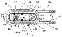
図10において、41はヒータ13bにより加熱される蒸気発生面であり、壁面33の内側面になる第一の蒸気発生面41aと、その蒸気発生面の周囲に形成され、開口32の内周側面になる第二の蒸気発生面41bとから構成されている。この蒸気発生面全体(但し、後述する温度検出部42を除く)は親水性の塗料が塗られている。図10において、Xは第一の蒸気発生面41aにおいて、前記筒状の給水口38の内側先端と向かい合う位置を示す。この位置に向かって給水口38からポンプ15によって水が注入される。なお、親水性塗料としてはたとえばグレベ(Grebe)の商品「番号:3111」やオキツモの商品「番号:8037K」が用いられているが、これに限定されるものではない。
In FIG. 10, reference numeral 41 denotes a steam generation surface heated by the
42は、図12に示すように第一の蒸気発生面41aに一体に形成された突起状の温度検出部であり、加熱容器13aの裏側、すなわち蒸気発生面41が形成されていない反対側の面から一定の深さに形成されている小孔44とネジ孔45がそれぞれ形成されており、前記サーミスタ等の温度検出器31のセンサー31aが小孔44に挿入され、センサー31aと一体になっている取付板53を固定するためのネジ52はネジ孔45に挿入されている。これら構造によりセンサー31aが第一の蒸気発生面41aの表面温度を敏感に検出できるようになっている。
As shown in FIG. 12, 42 is a protrusion-like temperature detection unit formed integrally with the first
前記温度検出部42の位置は、第一の蒸気発生面41aにおいて給水口38からポンプ15によって水が注入される位置X(図10参照)よりも僅か(この実施の形態では約10mm)下方である。このように、給水口に対向した位置の直下に温度検出器31のセンサー31aがあるので、蒸気発生面41の上に実際に給水されたことが即座に検知できるため、蒸気発生用の熱源であるヒータ13bの通電をタイムリーにコントロールできる。
The position of the
なお、蒸気発生面41を親水性塗料で塗装したのは、親水性により水が蒸気発生室(密閉空間)BMを形成する壁面や後述する複数の熱交換フィン46、47,49に広く展開し密着するようになるので蒸気化しやすくなるためである。また逆に温度検出部42にはそのような親水性塗料の皮膜は形成されていないので、温度検出器31のセンサー31aによる検出感度を損なうことがない。
Note that the steam generation surface 41 is coated with a hydrophilic paint because water is widely spread on the wall surface forming the steam generation chamber (sealed space) BM and a plurality of
46は図6、図10に示すように、第一の蒸気発生面41aの一方側に一体に形成された突起状の熱交換用フィンであり、それぞれ厚みは1〜2mm程度であり、4個が一定間隔(相互の間隔が約5mm)で一列に並んでいる。47は同じく図6、図10に示すように、第一の蒸気発生面41aにおいて、温度検出部42を挟んで前記熱交換用フィン46と反対側に一体に形成された突起状の熱交換用フィンであり、それぞれ厚みは1〜2mm程度であり、4個が一定間隔(相互間隔が約5mm)で一列に並んでいる。上記熱交換フィン46、47の突出高さ(第一蒸気発生面41aからの高さ)は約5mmに揃えてある。このため各熱交換フィン46、47の上端と蓋体35との間には約5mmの蒸気流通空間が確保されている。
As shown in FIGS. 6 and 10, 46 is a protruding heat exchange fin integrally formed on one side of the first
49は蒸気発生室(密閉空間)BMの下部の位置で第一の蒸気発生面41aに一体形成された熱交換用フィンであり、厚みは1〜2mm程度、密閉空間BMの最も低い底面から10mm程度の間隔を保ち、また蓋体35との間には約2mmの狭い蒸気流通空間が確保されるように、高さ約8mm程度に形成されている。
49 is a heat exchange fin integrally formed on the first
50は、蒸気発生室(密閉空間)BMの上部、すなわち壁面33を貫通するように3個形成された貫通孔34の内、2つの貫通孔34の直下位置に横に並べて一体成形された2つの熱交換用フィンであり、それぞれの厚みは1〜2mm程度、蓋体35との間には約2mmの狭い蒸気流通空間が確保できるように高さが約8mm程度に形成され、相互の対向間隔は約3mm、外側の第二の蒸気発生面41bとの対向間隔約2mmとなるような大きさになっている。
51は、熱交換用フィン50の更に上方位置に一体に形成された1つの熱交換フィンであり、熱交換フィン50と同様な大きさに形成されている。このように貫通孔34の直下に、熱交換用フィン50、51を設けているので、熱交換用フィン46、47、49の部分で十分加熱されて蒸気が上昇した場合、この蒸気はさらに熱交換用フィンの周囲の狭い通路を経て高所にある貫通孔34に至る間に十分加熱され、更に高温の過熱蒸気となる。
以上の構成であるから、加熱室2の内部を高温雰囲気にしておき、また貯水タンク14に水を貯めておき、ポンプ15を運転すれば貯水タンク14内部の水が第1給水管路16からポンプ15に吸引され、その吸引された水が第2給水管路17を通り、加熱容器13aの給水口38から蒸気発生面31のX位置に向けて注入される。
Since it is the above structure, if the inside of the heating chamber 2 is made into a high temperature atmosphere, and water is stored in the
蒸気発生面41は事前にヒータ13bにより高温に加熱されているため、注入された水は蒸気発生面41において給水口38に対向した位置Xを中心としてその近傍にまず衝突し、蒸気発生面41の高熱で蒸気化する。また瞬間に蒸気化しなかったものはそこから下方へ自重で流下する過程において、熱交換用フィン46、47に接触し、最も下方位置になる熱交換用フィン49に至る間に大部分が蒸気化する。
Since the steam generating surface 41 is heated to a high temperature by the
そしてこれら蒸気は熱交換用フィン46、47相互間の狭い間隙や蓋体35との狭い間隙を自ら上昇し、更に上昇した位置にある熱交換用フィン50、51で更に加熱され、更に高温の過熱蒸気となって最終的には蒸気発生室(密閉空間)BMの高所にある貫通孔34から噴出し、加熱室2内部に高温蒸気を充満させることができる。
These steams rise by themselves through a narrow gap between the
1 本体、2 加熱室、3 載置板、4 被加熱物、5 熱風循環手段(加熱手段)、6 マグネトロン(加熱手段)、13 蒸気発生手段、13a 加熱容器、 13b ヒータ(発熱体)、14 貯水タンク、14a タンク容器、14b 上蓋、15 ポンプ、16 第1給水管路、17 第2給水管路、19 給水パイプ、20 つゆ・タンク受け部材、21 つゆ受け部、22 タンク受け部、23 水受け部、29 ジョイント部、 31 温度検出器、 31a センサー、 34 貫通孔、 35 蓋体、38 給水口、 41 蒸気発生面、 41a 第一の蒸気発生面、 41b 第二の蒸気発生面、42 温度検出部、 46熱交換用フィン、 47 熱交換用フィン、 49 熱交換用フィン、50 熱交換用フィン、 BM 蒸気発生室(密閉空間)。
DESCRIPTION OF
Claims (13)
前記加熱容器の外部からその蒸気発生面に供給された水を加熱し蒸気を発生させる発熱体を有し、
前記加熱容器は、内側に前記蒸気発生面を有し、一側面に開口を形成した本体と、この本体の前記開口を閉塞するように前記本体に取り付けられる蓋体とを備え、
前記蒸気発生面には蒸気を該加熱容器の外部に噴出する開口が形成され、前記蓋体には給水口が形成されており、
該加熱容器は、前記蒸気発生面が垂直又は斜めに傾斜した状態で用いられ、
前記発熱体は通電を行うことにより発熱するヒーターであり、前記加熱容器の内部に設けられ、両端に端子部を有する略U字形状をなしており、該端子部が前記加熱容器より上方となるように前記加熱容器に設けられ、
前記蒸気発生面には、前記加熱容器の外部から供給された水がそれ自身で下降することを抑制するように突起状の熱交換用フィンを互いに所定間隔を置いて複数個一体に形成されており、
該熱交換用フィンは、その最上部と前記蓋体との対向部分に所定の間隙が形成されるような高さを有し、当該間隙が前記蒸気発生面で発生した蒸気の通路になることを特徴とする蒸気発生器。 A heating container formed of a thermally conductive material having a sealed internal space and having a steam generating surface provided on at least one wall surface forming the space;
A heating element for generating steam by heating water supplied to the steam generating surface from the outside of the heating container;
The heating container includes a main body having the vapor generation surface on the inner side and an opening formed on one side surface, and a lid attached to the main body so as to close the opening of the main body.
An opening for ejecting steam to the outside of the heating container is formed on the steam generating surface, and a water supply port is formed on the lid.
The heating container is used in a state where the steam generation surface is inclined vertically or obliquely,
The heating element is a heater that generates heat when energized. The heating element is provided inside the heating container and has a substantially U shape having terminal portions at both ends, and the terminal portion is located above the heating container. Provided in the heating vessel as
A plurality of protruding heat exchange fins are integrally formed at a predetermined interval on the steam generation surface so as to prevent water supplied from the outside of the heating container from descending by itself. And
The heat exchanging fin has such a height that a predetermined gap is formed between the uppermost portion and the lid, and the gap serves as a passage for the steam generated on the steam generating surface. A steam generator characterized by
前記蒸気発生手段は、
密閉された内部空間を有し、かつその空間を形成する少なくとも1壁面に垂直または斜めに傾斜した蒸気発生面が設けられた加熱容器と、
該加熱容器の蒸気発生面に向けて前記供給手段からの水を供給する給水パイプと、
前記蒸気発生面を加熱する発熱体と有し、
前記加熱容器は、内側に前記蒸気発生面を有し、一側面に開口を形成した本体と、該本体の前記開口を閉塞するように前記本体に取り付けられる蓋体とを備え、
前記蒸気発生面には蒸気を該加熱容器の外部に噴出する開口が形成され、前記蓋体には前記給水パイプが接続される給水口が形成されており、
前記発熱体は通電を行うことにより発熱するヒーターであり、前記加熱容器の内部に設けられ、両端に端子部を有する略U字形状をなしており、該端子部が前記加熱容器より上方となるように前記加熱容器に設けられ、
前記給水パイプから前記蒸気発生面の上に供給される水が、該蒸気発生面を下方に流れる過程で上記発熱体の熱を受けて蒸気化するように構成され、
前記蒸気発生面には、前記給水パイプとの対応部分より少なくとも下方領域に、給水パイプから供給された水がそれ自身で下降することを抑制するように突起状の熱交換用フィンを互いに所定間隔を置いて複数個形成され、
該熱交換用フィンは、その最上部と前記蓋体との対向部分に所定の間隙が形成されるような高さを有し、当該間隙が前記蒸気発生面で発生した蒸気の通路になるように構成されていることを特徴とする加熱調理器。 Heat cooking comprising a heating chamber for storing an object to be heated, heating means for heating the object to be heated, steam generating means for supplying steam to the heating chamber, and supply means for supplying water to the steam generating means In the vessel
The steam generating means includes
A heating vessel having a sealed internal space and provided with a steam generating surface that is perpendicular or obliquely inclined to at least one wall surface forming the space;
A water supply pipe for supplying water from the supply means toward the steam generation surface of the heating container;
A heating element for heating the vapor generating surface;
The heating container includes a main body having the vapor generation surface on the inside and an opening formed on one side surface, and a lid attached to the main body so as to close the opening of the main body.
The steam generation surface is formed with an opening for ejecting steam to the outside of the heating container, and the lid is formed with a water supply port to which the water supply pipe is connected,
The heating element is a heater that generates heat when energized. The heating element is provided inside the heating container and has a substantially U shape having terminal portions at both ends, and the terminal portion is located above the heating container. Provided in the heating vessel as
The water supplied on the steam generation surface from the water supply pipe is configured to be vaporized by receiving heat from the heating element in the process of flowing down the steam generation surface,
Protruding heat exchange fins are spaced apart from each other by a predetermined distance on the steam generation surface so as to prevent water supplied from the water supply pipe from descending at least in a region below the corresponding portion with the water supply pipe. A plurality is formed by placing
The heat exchanging fin has such a height that a predetermined gap is formed between the uppermost portion and the lid, and the gap serves as a passage for the steam generated on the steam generating surface. It is comprised in the heating cooker characterized by the above-mentioned.
Priority Applications (1)
| Application Number | Priority Date | Filing Date | Title |
|---|---|---|---|
| JP2007226113A JP5070999B2 (en) | 2007-08-31 | 2007-08-31 | Steam generator and cooking device using the same |
Applications Claiming Priority (1)
| Application Number | Priority Date | Filing Date | Title |
|---|---|---|---|
| JP2007226113A JP5070999B2 (en) | 2007-08-31 | 2007-08-31 | Steam generator and cooking device using the same |
Publications (3)
| Publication Number | Publication Date |
|---|---|
| JP2009058185A JP2009058185A (en) | 2009-03-19 |
| JP2009058185A5 JP2009058185A5 (en) | 2009-07-30 |
| JP5070999B2 true JP5070999B2 (en) | 2012-11-14 |
Family
ID=40554081
Family Applications (1)
| Application Number | Title | Priority Date | Filing Date |
|---|---|---|---|
| JP2007226113A Expired - Fee Related JP5070999B2 (en) | 2007-08-31 | 2007-08-31 | Steam generator and cooking device using the same |
Country Status (1)
| Country | Link |
|---|---|
| JP (1) | JP5070999B2 (en) |
Families Citing this family (8)
| Publication number | Priority date | Publication date | Assignee | Title |
|---|---|---|---|---|
| JP5394674B2 (en) * | 2008-08-08 | 2014-01-22 | シャープ株式会社 | Steam generator and cooking device |
| WO2010134930A1 (en) * | 2009-05-16 | 2010-11-25 | Ideas Well Done Llc | Food steamer containers with sequential ohmic water heating |
| JP5075925B2 (en) * | 2010-01-20 | 2012-11-21 | 日立アプライアンス株式会社 | Cooker |
| JP2011149643A (en) * | 2010-01-22 | 2011-08-04 | Sharp Corp | Heat cooking apparatus |
| JP6010764B2 (en) * | 2013-03-13 | 2016-10-19 | パナソニックIpマネジメント株式会社 | Steam generator |
| JP6496498B2 (en) * | 2014-06-27 | 2019-04-03 | シャープ株式会社 | Cooker |
| KR101597108B1 (en) * | 2014-12-19 | 2016-02-24 | 엘지전자 주식회사 | Fabric treating apparatus |
| CN104633630A (en) * | 2015-02-13 | 2015-05-20 | 余姚市吉佳电器有限公司 | Novel boiler of steam mop |
Family Cites Families (3)
| Publication number | Priority date | Publication date | Assignee | Title |
|---|---|---|---|---|
| JPS5072779U (en) * | 1973-11-12 | 1975-06-26 | ||
| JP3753135B2 (en) * | 2003-05-19 | 2006-03-08 | 松下電器産業株式会社 | High-frequency heating device with steam generation function |
| JP4421430B2 (en) * | 2004-09-14 | 2010-02-24 | 株式会社東芝 | Cooker |
-
2007
- 2007-08-31 JP JP2007226113A patent/JP5070999B2/en not_active Expired - Fee Related
Also Published As
| Publication number | Publication date |
|---|---|
| JP2009058185A (en) | 2009-03-19 |
Similar Documents
| Publication | Publication Date | Title |
|---|---|---|
| JP5070999B2 (en) | Steam generator and cooking device using the same | |
| WO2010024381A1 (en) | Cooking device | |
| JP3800190B2 (en) | High-frequency heating device with steam generation function | |
| JP4051384B2 (en) | Superheated steam cooker | |
| JP2005326086A (en) | Steam cooker | |
| WO2011136252A1 (en) | Cooking device | |
| JP2016099010A (en) | Heating cooker | |
| JP2009019828A (en) | Cooker | |
| JP2012122675A (en) | Heating cooker | |
| JP4576296B2 (en) | Cooker | |
| JP2020094736A (en) | Cooking device | |
| JP3753135B2 (en) | High-frequency heating device with steam generation function | |
| JP6503127B2 (en) | Cooker | |
| JP4994487B2 (en) | Cooker | |
| JP6468672B1 (en) | Cooker | |
| JP4473043B2 (en) | Steam cooker | |
| JPH0228058B2 (en) | KANETSUCHORISOCHI | |
| JP6463280B2 (en) | Cooker | |
| JP3767574B2 (en) | High-frequency heating device with steam generation function | |
| JP5856657B2 (en) | Cooker | |
| JP4994479B2 (en) | Cooker | |
| JP5755790B2 (en) | Cooker | |
| JP5160347B2 (en) | Steam generator and cooking device | |
| JP2013213668A (en) | Heating cooker | |
| JP2010054172A (en) | Steam generator |
Legal Events
| Date | Code | Title | Description |
|---|---|---|---|
| A521 | Written amendment |
Free format text: JAPANESE INTERMEDIATE CODE: A523 Effective date: 20090617 |
|
| A621 | Written request for application examination |
Free format text: JAPANESE INTERMEDIATE CODE: A621 Effective date: 20090617 |
|
| A977 | Report on retrieval |
Free format text: JAPANESE INTERMEDIATE CODE: A971007 Effective date: 20110726 |
|
| A131 | Notification of reasons for refusal |
Free format text: JAPANESE INTERMEDIATE CODE: A131 Effective date: 20110802 |
|
| A521 | Written amendment |
Free format text: JAPANESE INTERMEDIATE CODE: A523 Effective date: 20110929 |
|
| A131 | Notification of reasons for refusal |
Free format text: JAPANESE INTERMEDIATE CODE: A131 Effective date: 20111101 |
|
| A521 | Written amendment |
Free format text: JAPANESE INTERMEDIATE CODE: A523 Effective date: 20111212 |
|
| A131 | Notification of reasons for refusal |
Free format text: JAPANESE INTERMEDIATE CODE: A131 Effective date: 20120214 |
|
| A521 | Written amendment |
Free format text: JAPANESE INTERMEDIATE CODE: A523 Effective date: 20120405 |
|
| TRDD | Decision of grant or rejection written | ||
| A01 | Written decision to grant a patent or to grant a registration (utility model) |
Free format text: JAPANESE INTERMEDIATE CODE: A01 Effective date: 20120724 |
|
| A01 | Written decision to grant a patent or to grant a registration (utility model) |
Free format text: JAPANESE INTERMEDIATE CODE: A01 |
|
| A61 | First payment of annual fees (during grant procedure) |
Free format text: JAPANESE INTERMEDIATE CODE: A61 Effective date: 20120806 |
|
| R150 | Certificate of patent or registration of utility model |
Free format text: JAPANESE INTERMEDIATE CODE: R150 |
|
| FPAY | Renewal fee payment (event date is renewal date of database) |
Free format text: PAYMENT UNTIL: 20150831 Year of fee payment: 3 |
|
| R250 | Receipt of annual fees |
Free format text: JAPANESE INTERMEDIATE CODE: R250 |
|
| R250 | Receipt of annual fees |
Free format text: JAPANESE INTERMEDIATE CODE: R250 |
|
| LAPS | Cancellation because of no payment of annual fees |