JP5856080B2 - Lens with continuous power gradation - Google Patents
Lens with continuous power gradation Download PDFInfo
- Publication number
- JP5856080B2 JP5856080B2 JP2012551146A JP2012551146A JP5856080B2 JP 5856080 B2 JP5856080 B2 JP 5856080B2 JP 2012551146 A JP2012551146 A JP 2012551146A JP 2012551146 A JP2012551146 A JP 2012551146A JP 5856080 B2 JP5856080 B2 JP 5856080B2
- Authority
- JP
- Japan
- Prior art keywords
- lens
- power
- lens surface
- optical
- region
- Prior art date
- Legal status (The legal status is an assumption and is not a legal conclusion. Google has not performed a legal analysis and makes no representation as to the accuracy of the status listed.)
- Active
Links
- 230000003287 optical effect Effects 0.000 claims description 126
- 230000004438 eyesight Effects 0.000 claims description 72
- 208000001491 myopia Diseases 0.000 claims description 56
- 230000008859 change Effects 0.000 claims description 43
- 238000012937 correction Methods 0.000 claims description 38
- 238000013461 design Methods 0.000 description 59
- 230000000750 progressive effect Effects 0.000 description 42
- 238000007792 addition Methods 0.000 description 33
- 230000005540 biological transmission Effects 0.000 description 21
- 230000008901 benefit Effects 0.000 description 18
- 238000000034 method Methods 0.000 description 15
- 238000004364 calculation method Methods 0.000 description 12
- 238000012545 processing Methods 0.000 description 12
- 238000005457 optimization Methods 0.000 description 10
- 201000010041 presbyopia Diseases 0.000 description 10
- 210000003205 muscle Anatomy 0.000 description 7
- 239000011521 glass Substances 0.000 description 6
- 238000002834 transmittance Methods 0.000 description 6
- 201000009310 astigmatism Diseases 0.000 description 5
- 238000011161 development Methods 0.000 description 5
- 230000018109 developmental process Effects 0.000 description 5
- 238000013459 approach Methods 0.000 description 4
- 230000007423 decrease Effects 0.000 description 4
- 230000000694 effects Effects 0.000 description 4
- 239000000463 material Substances 0.000 description 4
- 239000000203 mixture Substances 0.000 description 4
- 244000035744 Hura crepitans Species 0.000 description 3
- 238000005520 cutting process Methods 0.000 description 3
- 239000000835 fiber Substances 0.000 description 3
- 230000006870 function Effects 0.000 description 3
- 238000004519 manufacturing process Methods 0.000 description 3
- 210000001747 pupil Anatomy 0.000 description 3
- 230000002829 reductive effect Effects 0.000 description 3
- 230000009286 beneficial effect Effects 0.000 description 2
- 210000004087 cornea Anatomy 0.000 description 2
- 238000006073 displacement reaction Methods 0.000 description 2
- 238000009826 distribution Methods 0.000 description 2
- 238000005516 engineering process Methods 0.000 description 2
- 230000004424 eye movement Effects 0.000 description 2
- 210000000720 eyelash Anatomy 0.000 description 2
- 210000000887 face Anatomy 0.000 description 2
- 230000006872 improvement Effects 0.000 description 2
- 230000000670 limiting effect Effects 0.000 description 2
- 230000002093 peripheral effect Effects 0.000 description 2
- 230000008569 process Effects 0.000 description 2
- 230000001373 regressive effect Effects 0.000 description 2
- 230000002441 reversible effect Effects 0.000 description 2
- 239000004576 sand Substances 0.000 description 2
- 238000004381 surface treatment Methods 0.000 description 2
- 230000000007 visual effect Effects 0.000 description 2
- 206010020675 Hypermetropia Diseases 0.000 description 1
- 230000004308 accommodation Effects 0.000 description 1
- 230000009471 action Effects 0.000 description 1
- 230000032683 aging Effects 0.000 description 1
- 238000004458 analytical method Methods 0.000 description 1
- 239000011248 coating agent Substances 0.000 description 1
- 238000000576 coating method Methods 0.000 description 1
- 238000004040 coloring Methods 0.000 description 1
- 230000008602 contraction Effects 0.000 description 1
- 230000004418 eye rotation Effects 0.000 description 1
- 230000002349 favourable effect Effects 0.000 description 1
- 238000009472 formulation Methods 0.000 description 1
- 238000000227 grinding Methods 0.000 description 1
- 238000009499 grossing Methods 0.000 description 1
- 230000004305 hyperopia Effects 0.000 description 1
- 201000006318 hyperopia Diseases 0.000 description 1
- 238000005304 joining Methods 0.000 description 1
- 238000005259 measurement Methods 0.000 description 1
- 230000004335 moderate hyperopia Effects 0.000 description 1
- 238000000465 moulding Methods 0.000 description 1
- 230000004379 myopia Effects 0.000 description 1
- 230000036961 partial effect Effects 0.000 description 1
- 230000009467 reduction Effects 0.000 description 1
- 230000004044 response Effects 0.000 description 1
- 230000000284 resting effect Effects 0.000 description 1
- 238000013341 scale-up Methods 0.000 description 1
- 238000007790 scraping Methods 0.000 description 1
- 230000035945 sensitivity Effects 0.000 description 1
- 238000007493 shaping process Methods 0.000 description 1
- 230000006641 stabilisation Effects 0.000 description 1
- 238000011105 stabilization Methods 0.000 description 1
- 230000008719 thickening Effects 0.000 description 1
- 230000007704 transition Effects 0.000 description 1
- 239000013585 weight reducing agent Substances 0.000 description 1
- 210000000216 zygoma Anatomy 0.000 description 1
Images


Classifications
-
- G—PHYSICS
- G02—OPTICS
- G02C—SPECTACLES; SUNGLASSES OR GOGGLES INSOFAR AS THEY HAVE THE SAME FEATURES AS SPECTACLES; CONTACT LENSES
- G02C7/00—Optical parts
- G02C7/02—Lenses; Lens systems ; Methods of designing lenses
- G02C7/06—Lenses; Lens systems ; Methods of designing lenses bifocal; multifocal ; progressive
- G02C7/061—Spectacle lenses with progressively varying focal power
- G02C7/063—Shape of the progressive surface
- G02C7/065—Properties on the principal line
-
- G—PHYSICS
- G02—OPTICS
- G02C—SPECTACLES; SUNGLASSES OR GOGGLES INSOFAR AS THEY HAVE THE SAME FEATURES AS SPECTACLES; CONTACT LENSES
- G02C7/00—Optical parts
- G02C7/02—Lenses; Lens systems ; Methods of designing lenses
- G02C7/06—Lenses; Lens systems ; Methods of designing lenses bifocal; multifocal ; progressive
- G02C7/061—Spectacle lenses with progressively varying focal power
- G02C7/068—Special properties achieved by the combination of the front and back surfaces
Description
人間の視力を矯正するための眼科用レンズが、何世紀もの間使用されている。しかし、材料や光学設計の新たな開発によって、より多くの選択肢や様々な改良がレンズ着用者に提供され続けている。 Ophthalmic lenses for correcting human vision have been used for centuries. However, new developments in materials and optical designs continue to provide more options and various improvements to lens wearers.
一例として、加齢による焦点調節の低下(人が年をとるにつれて「老眼鏡が必要になる」という一般的な現象)に対処するための開発の歴史を考えよう。眼の水晶体は、筋肉及び繊維の精緻な枠組みの内部に保持されており、この筋肉及び繊維の収縮・弛緩によって変形するのに十分な柔軟性を有している。従って、筋肉及び繊維の作用によって、眼の水晶体の形状、ひいてはその焦点距離が変化する。「安静状態」とは、筋肉が弛緩して、焦点距離が長くなるように水晶体が湾曲の小さい形態にある、遠方視の状態をいう。近方視では、筋肉は緊張し、水晶体はより丸くなって近傍の物体に焦点を合わせる。遠い景色と近傍の物体とを見る時、眼は自動的にその眼の中の筋肉を調節して眼の水晶体の焦点を合わせ直そうとする。しかしながら年をとると、水晶体は固くなり始め、筋肉の変化に敏速に対応できなくなる。正式には老眼として知られるこの調節の低下のために、眼を補助するための何らかの視力矯正が必要となる。 As an example, consider the history of development to deal with the decline in focus adjustment due to aging (a common phenomenon that “needs reading glasses” as people get older). The lens of the eye is held inside a fine framework of muscles and fibers, and has sufficient flexibility to be deformed by contraction / relaxation of the muscles and fibers. Therefore, the shape of the lens of the eye, and hence its focal length, changes due to the action of muscles and fibers. The “resting state” refers to a state of far vision where the lens is in a small curved form so that the muscle is relaxed and the focal length is increased. In near vision, the muscles are tense and the lens becomes more rounded to focus on nearby objects. When looking at a distant view and nearby objects, the eye automatically adjusts the muscles in the eye to refocus the eye lens. However, as we get older, the lens begins to harden and cannot respond quickly to muscle changes. This reduction in accommodation, formally known as presbyopia, requires some vision correction to assist the eye.
それまで視力矯正をしたことがない人々に対する簡単な手法としては、近方視目的のためにより高い度数を与える単焦点眼鏡の使用がある。しかしながら、このレンズを通して遠くの物体を見ると、そのレンズによって人の自然な視力が近視眼的になってしまうため、視界がぼやけてしまう。同様の効果は、拡大鏡を通して遠くの物体を見た場合にも見られる。この時点で即座に眼鏡を外すと、眼鏡を置き間違えるという問題が起こり得る。代替案として、ベンジャミン・フランクリンと彼の二重焦点レンズを考える人もいるだろう。このようなレンズは、遠用矯正用の一次面曲率と、(必要であれば)近方視目的のためのより高い度数を与える加入度数セグメントとを有する。より高い度数を実現するために、この加入度数セグメントは、より急峻なレンズ曲率を有し、従って、このセグメントは一次レンズ面よりも突出している。多くの人々は、この眼鏡の眼に見える線及び段差のために、二重焦点レンズを嫌う。 A simple technique for people who have not previously corrected vision is the use of single-focus glasses that provide higher power for near vision purposes. However, when a distant object is viewed through this lens, the natural vision of the person becomes myopic due to the lens, and the field of vision is blurred. A similar effect is seen when looking at distant objects through a magnifier. If the glasses are removed immediately at this point, there may be a problem that the glasses are misplaced. As an alternative, one might think of Benjamin Franklin and his bifocal lens. Such lenses have a primary curvature for distance correction and an add power segment that gives higher power for near vision purposes (if necessary). In order to achieve a higher power, this add power segment has a steeper lens curvature and therefore this segment protrudes beyond the primary lens surface. Many people hate bifocal lenses because of the visible lines and steps in the glasses.
遠方視ゾーンと近方視ゾーンとの間の領域をブレンドするための当初の努力(ブレンド二重焦点レンズ)によって、レンズ上の度数外(off−power)領域に着用者が耐えることができるか否かに関する認識が高められた。多くの眼鏡着用者は、度数が低いことによるエラー(典型的には約0.5ディオプター未満)に耐えることができるが、度数の変化に対して非常に敏感な人もいる。これは、かつて「完全な視力」を有し、現在初めて近方視のための視力矯正が必要になった個人にとって特に問題となる。たとえ実際に測定された度数変化が非常に小さくても、完全な視力からの如何なる変化も非常に大きなものに感じられる。同様に、ブレンド設計に関する研究によって、レンズ上の度数外領域の物理的な位置及び該度数外領域の物理的サイズに対する着用者の感度が明らかにされた。ブレンド設計では、レンズの遠方矯正ゾーンとより度数の高い近用ゾーンとの間に、典型的にはほんの数mmの広さの狭領域が存在する。この狭領域において度数は、遠方視度数と近方視度数との差と同程度少なくとも変化する。近方視領域のために増加させる光学度数、つまり「加入度数」は典型的に0.5ディオプター以上から約4ディオプターまでの範囲にあるため、このことは、多くの人が、眼がブレンド領域を横断する際、ぼやけを感じることを意味する。これは、レンズ着用者を見る他の人にはブレンド領域が見えなくても、使用者にとっては非常に悩ましい場合がある。このため、このような度数外領域の面積を最小化したり、度数変化を漸進的に変化させて耐え得るものとするようにしたり、度数外領域をレンズ上における使用頻度のより低い位置(周縁部等)に移したりするように設計された更なる開発が行なわれている。 Can the initial effort to blend the area between the far vision zone and the near vision zone (blend bifocal lens) allow the wearer to withstand the off-power area on the lens? Awareness about whether or not was raised. Many spectacle wearers can tolerate errors due to low power (typically less than about 0.5 diopters), but some are very sensitive to power changes. This is particularly problematic for individuals who once had “perfect vision” and now need vision correction for near vision for the first time. Even if the actual measured power change is very small, any change from perfect vision is felt very large. Similarly, blend design studies have revealed the wearer's sensitivity to the physical location of the out-of-power region on the lens and the physical size of the out-of-power region. In a blend design, there is a narrow region, typically only a few millimeters wide, between the lens's deep correction zone and the higher power near zone. In this narrow region, the power changes at least as much as the difference between the distance vision power and the near vision power. This increases the optical power, or “add power,” for the near vision region, typically in the range of more than 0.5 diopters to about 4 diopters. It means that you feel blurry when crossing. This can be very annoying to the user even if the blended area is not visible to others viewing the lens wearer. For this reason, the area of such an out-of-frequency area is minimized, the change in the frequency is gradually changed so as to be able to withstand, or the out-of-frequency area is located on the lens at a less frequently used position (periphery portion). Etc.) and further developments are being designed.
例えば、特許文献1及び2等の特許には、一方の表面に漸進的に増加する度数を設けて(曲率半径を変化させて)使用者にこのレンズ全体に亘る広い範囲の焦点距離を与えるレンズが記載されている。これらのレンズは、上記した二重焦点レンズやブレンド二重焦点レンズのように、漸進的に度数が増加する表面上に一定の度数の球面領域を有してもよい。レンズの他方側は、処方箋に従って研削加工を施すと記載されており、これは典型的に遠方視矯正を意味する。これらの特許が付与された時点において、研削技術は、その効果的に、他面を球面状や円筒状に成型する加工に限られていたはずである。これは、レンズの多くに、ブレンド二重焦点レンズと同じ制限、つまり、度数の連続的な増加によって視界がぼやけてしまうという問題が生じていた。
For example, in patents such as
以前のこうした技術が直面していた制限や困難は、過去数十年に亘るレンズ設計の開発を他の手法に向けることになった。特許文献3,4,5,及び6等の特許によって証拠付けられるように、遠方視用の安定度数をもつ一領域と、近方視用の安定度数をもつ他領域と、これら2つの領域の度数値の一方から他方に連続的且つ漸進的に度数が変化する、これらの領域間の典型的には狭い領域とを備えるレンズを作成することができた。これら3つの領域を有するレンズは、一般的に、累進レンズと称される。
The limitations and difficulties previously faced by these technologies have led to the development of lens designs over the past decades to other approaches. As evidenced by patents such as
累進設計は一般的に、眼鏡レンズの上端部近傍に遠方視領域を有する。一例として、着用者が2ディオプターの中程度の遠視矯正を必要とする場合を想定しよう。つまり遠方視領域において、着用者のレンズの矯正度数は2ディオプターである。ここで、例えば、着用者が初期の老視患者であり、近用(読書用)のために1ディオプターの軽い度数補助(1ディオプターの加入度数と称する場合もある)が必要な場合を想定しよう。従って、レンズの第2の近方視領域において、安定度数は3ディオプター(全体の視力矯正のための2ディオプター+近方視の追加矯正のための1ディオプター)となる。近方視領域は一般的にレンズの下端部近傍且つ多くの場合若干鼻側に位置付けられるが、これは、着用者が本や手作業を下方に見る方向に整合しており、若干内側に位置付けられることによって、近方視領域での眼の両眼追跡を収容している。典型的に、使用者が遠視及び近視矯正に対する略一定且つ安定化された度数の「水平域(plateau)」を使用者が得られるように、遠方視領域及び近方視領域を出来るだけ大きく設計することが試みられる。特に、遠方視領域は、使用されうる視野角の幅のために大きく取るべきである。近方視領域は、より小さくできるが、それでもより明瞭な近用(読書用)視力を得るために少なくとも瞳孔の幅を収容できなければならず、好ましくは読書中の眼の回転に対する小さい角度の範囲を定める。従って、安定加入度数の近方視領域を少なくとも数ミリメートルの幅とするのが一般的である。この上端部領域と下端部領域との間において、光学度数は、高い近方視の値に急速に変化させる必要がある。この例において、これは2ディオプターから3ディオプターまでの変化である。この累進領域又は帯域は、変曲点によって特徴付けられ、典型的には比較的狭く且つ短く維持される。これは、それが所望の遠方視度数でも近方視度数でもないためであり、また以下に説明するように、物理的な必要性のためである。 Progressive designs typically have a far vision region near the upper end of the spectacle lens. As an example, suppose the wearer needs moderate hyperopia correction of 2 diopters. That is, in the far vision region, the correction power of the wearer's lens is 2 diopters. Here, for example, assume that the wearer is an early presbyopic patient and needs 1 diopter light power assistance (sometimes referred to as 1 diopter addition power) for near vision (for reading). . Thus, in the second near vision region of the lens, the stability number is 3 diopters (2 diopters for overall vision correction + 1 diopter for additional near vision correction). The near vision area is generally located near the lower end of the lens and often slightly to the nose, but this is aligned with the wearer's direction of looking down at books and manual work and is located slightly inward. This accommodates binocular tracking of the eye in the near vision region. Typically, the far vision and near vision areas are designed to be as large as possible so that the user can obtain a “plateau” of approximately constant and stabilized power for hyperopia and myopia correction. It is tried to do. In particular, the far vision area should be large due to the width of the viewing angle that can be used. The near vision region can be smaller, but it must still be able to accommodate at least the width of the pupil in order to obtain clearer near vision (reading) vision, preferably with a small angle to the eye rotation during reading. Define the scope. Therefore, the near vision region with a stable addition power is generally at least a few millimeters wide. Between the upper end region and the lower end region, the optical power needs to be rapidly changed to a high near vision value. In this example, this is a change from 2 to 3 diopters. This progressive region or band is characterized by an inflection point and is typically kept relatively narrow and short. This is because it is not the desired distance diopter or near diopter power, and because of the physical need as explained below.
このような累進的に増加する度数を実現するのは更に複雑である。より高い度数の領域を形成するためには、レンズの物理的な表面を変形させてより鋭く湾曲させる必要がある。表面の一部をより高い度数へと変形させるプロセスにおいて、度数外値(及び光学的非点収差)を有する他の領域が形成される。このことは大まかに、砂を箱から取り出したり箱に追加したりすることなく箱の中の砂を移動させる行為に例えることができる。従って、丘(度数の高い領域の例え)を作るためには、砂をある領域に積み上げるとともに他の領域からかき出す必要がある。砂箱を本来の高さ(本来の遠方視度数の例え)に維持したい場合、かき出す面積を広げて砂箱の残りの部分との高低差の大きさを減らす必要がある。しかしながら、これは、処方された遠方視度数に対する「ある程度の」ばらつきがみられる領域が広がることを意味し、前に示したように、人によっては、このような度数のばらつきに対して非常に敏感である。代替案として、より小さな領域で深く掘り下げて、より度数の外れた(本来の砂箱の高さからの差がより大きい)領域をはっきりと形成することも考えられる。これらの問題は、2つの光学度数の差が大きく(「丘」が高く)なればなるほど深刻になる。これらは、光学度数の変化を含むレンズ設計に伴う、実際的、機械的及び物理的な制限である。 Realizing such progressively increasing frequencies is even more complex. In order to form a higher power region, it is necessary to deform the physical surface of the lens to be bent more sharply. In the process of deforming a portion of the surface to a higher power, other regions with out-of-power values (and optical astigmatism) are formed. This can be roughly compared to the act of moving sand in a box without removing it from the box or adding it to the box. Therefore, in order to create a hill (an example of a high frequency area), it is necessary to pile up sand in one area and scrape it from another area. If you want to keep the sandbox at its original height (an example of the original distance diopter), you need to widen the scraping area and reduce the height difference from the rest of the sandbox. However, this means that there is a wider range of “somewhat” variation in the prescribed distance diopter power, and as indicated earlier, some people are very sensitive to such power variation. Sensitive. As an alternative, it is possible to dig deeper in a smaller area to form a more off-the-shelf area (a greater difference from the original sandbox height). These problems become more serious as the difference between the two optical powers increases (the “hill” is higher). These are practical, mechanical and physical limitations associated with lens designs that include changes in optical power.
代替例として、特許文献7には、段差を有するフレネル光学素子に屈折レンズ面を組み合わせて光学度数の異なる領域を形成することが記載されている。これは、レンズ材料の屈折能力のみを使用するものとは全く異なる手法であり、フレネルの不連続な複数段のパターンによる制限がありうる。例えば、フレネルの段差により散乱する光が増加して、着用者にとって悩ましくなったり、外観が非審美的なものになったりしうる。また、複数の段差を有する構造に亘って光学的透明度が歪んだり欠けたりすることも考えられる。
As an alternative example,
上記した特許の幾つかに説明されまた当該技術分野の通常の技能を有する者にとって既知のように、累進設計は、眼鏡レンズのレンズ外面(着用者から遠い面、言い換えるとレンズの「前面」)又はレンズ内面(眼に近い面、言い換えると「裏面」)のいずれかに組み込むことができる。これは、多くの場合、「累進セミフィニッシュレンズブランク」により実現される。累進セミフィニッシュレンズブランクは、一方の面に、比較的大きい有効安定遠方視領域と、遠用度数よりも高い既知の安定度数を有する他の近方視領域と、これら2つのゾーン間に延在し、累進的に増加する光学度数と変曲点によって特徴付けられる比較的狭く、短い帯域(中間部)とを組み込んだものである。そして、個々の着用者に対する処方は、このセミフィニッシュブランクの他方の面を切削・円滑化することによって使用者に必要な特定の光学度数にすることによって「仕上げ」られる。累進セミフィニッシュレンズブランクでは、典型的に、他方のレンズ面を遠方視矯正用に仕上げ、累進面を全ての近方視矯正を提供するために使用する。 As described in some of the above-mentioned patents and known to those having ordinary skill in the art, the progressive design is the lens outer surface of the spectacle lens (the surface far from the wearer, in other words the “front surface” of the lens). Alternatively, it can be incorporated on either the inner surface of the lens (the surface close to the eye, in other words, the “back surface”). This is often achieved by a “progressive semi-finished lens blank”. Progressive semi-finished lens blanks extend between these two zones on one side with a relatively large effective stable distance vision region and other near vision regions with a known stability power higher than the distance power. However, it incorporates a relatively narrow and short band (intermediate portion) characterized by progressively increasing optical power and inflection points. The prescription for the individual wearer is then “finished” by cutting and smoothing the other side of the semi-finished blank to the specific optical power required by the user. In progressive semi-finished lens blanks, the other lens surface is typically finished for far vision correction and the progressive surface is used to provide all near vision correction.
代替例として、例えば、特許文献8,9,及び10に記載されているように、両面に累進設計を組み込むことも考えられる。代替の関連のある他の手法が、特許文献11及び12等の特許に記載されており、ここでは、一方の表面を累進設計とし、他方の表面を「逆進(regressive)」面、つまり遠方視領域と近方視領域との間において度数が減少する面としている。この逆進面は、レンズの内面又は外面のいずれに配置してもよい。 As an alternative, it is also conceivable to incorporate progressive designs on both sides, for example as described in US Pat. Other relevant alternative approaches are described in patents such as US Pat. Nos. 6,099,637 and 5,037, in which one surface is a progressive design and the other surface is a "regressive" surface, i.e., far away. The frequency decreases between the viewing area and the near vision area. The reverse surface may be disposed on either the inner surface or the outer surface of the lens.
レンズの内面に加入度数を配置、又は処方度数を両面で共有することによって、光学設計の自由度を高めることが可能になり、美的外観上の利点も得られる。これらの選択肢は、市場において、CNC機械に基づくデジタル表面加工設備の発展によっても更に後押しされており、光学表面の一方又は両方の成形をより複雑化・制御化できる可能性がある。 By arranging the addition power on the inner surface of the lens or sharing the prescription power by both sides, it becomes possible to increase the degree of freedom in optical design, and an aesthetic appearance advantage is also obtained. These options are further boosted in the market by the development of digital surface processing equipment based on CNC machines, which may allow more complex and controlled shaping of one or both optical surfaces.
加齢に関連した視力矯正や多くの人々のファッション意識に対する継続的なニーズを考慮すると、光学性能や身体的心地良さ、美的外観は、全て大変重要であるということは驚くことではない。これらの要素は、レンズ着用者を見た人にとって小さく目立たないようにする内面の累進形状の再人気化において重要な役割を果たしてきた。内面累進形状では、加入部分が外面から前方に突出しないからである。しかしながら、このようなレンズは、増加させた加入度数を着用者の眼に対して収容する必要があるため、着用者にとっては問題となりうる。これは、レンズの裏面が、単焦点処方のそれよりも、或いは、前(外)面に累進度数を有するレンズのそれよりも、湾曲が小さく(浅い凹形状)となることを意味する。高プラスの処方のためには、単焦点レンズであってもその裏面又は内面は、高マイナス度数レンズよりも平坦となる。(標準的な裏面累進設計のように)プラスレンズの内面下端部に近方視度数を追加すると、レンズの内面はなお平坦となって、使用者の頬やまつ毛に接触する場合がある。この問題を回避又は最小限に抑えるための1つの方法は、より急峻な前面曲率を有するレンズを使用して、レンズの内面に加入度数を形成するための空間をより大きく取ることである。しかしながら、より大きく曲線を得るためには、より平坦な局面との組み合わせと同じ加入度数を形成するのでより多くのレンズ材料が必要となり、その結果レンズが全体的により重く又は厚くなりうる。また、より湾曲したレンズを使用することによって、累進前面の球状の外観を低減するというこれまで求められてきた利点が打ち消されてしまう。 Given the ongoing needs for age-related vision correction and the fashion awareness of many people, it is not surprising that optical performance, physical comfort and aesthetic appearance are all very important. These elements have played an important role in the repopularization of the progressive shape of the inner surface that makes it small and inconspicuous for those who see the lens wearer. This is because, in the inner surface progressive shape, the joining portion does not protrude forward from the outer surface. However, such lenses can be problematic for the wearer because the increased power needs to be accommodated by the wearer's eyes. This means that the back surface of the lens is less curved (shallow concave shape) than that of a single focus prescription or that of a lens with a progressive power on the front (outer) surface. For a high plus prescription, the back or inner surface of a single focus lens is flatter than a high minus power lens. When near vision power is added to the lower end of the inner surface of the plus lens (as in the standard backside progressive design), the inner surface of the lens may still be flat and come into contact with the user's cheeks or eyelashes. One way to avoid or minimize this problem is to use a lens with a steeper front curvature and allow more space to form add power on the inner surface of the lens. However, to obtain a larger curve, more lens material is required because it forms the same add power as the combination with the flatter aspect, so that the lens can be heavier or thicker overall. In addition, the use of a more curved lens negates the previously sought advantage of reducing the spherical appearance of the progressive front.
同じ難しさは、高マイナス処方及び内面の加入度数に対しても当てまはる。高マイナスレンズは、正確なレンズ効果を作り出せるようレンズ内面の曲率半径が典型的に外面の曲率半径よりも急峻なため、周縁が厚くなっている。基本曲線がより急峻なレンズを前(外)面に使用して裏面累進設計を収容する場合、レンズはより大きく且つ不要な厚さを有し、通常のマイナス処方よりも球状の外観を帯びることになる。 The same difficulty applies to high minus prescriptions and internal power additions. A high minus lens has a thicker periphery because the radius of curvature of the inner surface of the lens is typically steeper than the radius of curvature of the outer surface to produce an accurate lens effect. If a lens with a steeper basic curve is used on the front (outer) surface to accommodate a back progressive design, the lens will have a larger and unnecessary thickness and will have a more spherical appearance than a normal negative prescription. become.
難しさと非最適とのトレードオフは、裏面累進レンズをフレームに嵌める時にも起こる。裏面の加入度数を収容するためにより急峻な基本曲線を使用する場合、突出しないようにレンズの周縁をフレーム内のより裏側に位置付けようと望む。しかしながら、これによって内面又は内面の周縁が着用者の顔に接触する場合がある。また、フレーム形状やラップ(wrap)角によって、レンズを固定的に又は審美的に嵌めるのが難しい場合がある。裏側累進設計によって周縁が厚くなると、眼鏡を魅力的でバランスのとれたものとするのが難しくなる。従って、裏面累進設計を採用する場合幾つかの異なる懸案事項に対処する必要がある。 The trade-off between difficulty and non-optimality also occurs when the back progressive lens is fitted into the frame. When using a steeper basic curve to accommodate the addition power on the back side, it is desirable to position the periphery of the lens on the back side in the frame so that it does not protrude. However, this may cause the inner surface or the periphery of the inner surface to contact the wearer's face. Also, depending on the frame shape and wrap angle, it may be difficult to fit the lens fixedly or aesthetically. Thickening the periphery due to the backside progressive design makes it difficult to make the glasses attractive and balanced. Therefore, several different concerns need to be addressed when employing backside progressive design.
2つの面の間で度数を共有することによって、厚さ及び度数プロファイルを分布させる選択肢は増えるが、設計の複雑さが顕著に増すため、完成レンズを製造するためのコスト、時間及びリソースが高くなる。また、処方度数の異なる部分をどのように分布させるかに応じて、内面の厚さの増加(それによる着用者の顔又はまつ毛への接触)や、前面の過剰な曲率、レンズの重量増加等の問題は依然としてある。 Sharing power between the two surfaces gives you more options to distribute the thickness and power profile, but significantly increases the complexity of the design, which increases the cost, time and resources to produce the finished lens. Become. Also, depending on how the prescription power is distributed, the thickness of the inner surface (the resulting contact with the wearer's face or eyelashes), excessive curvature on the front surface, increased weight of the lens, etc. The problem is still.
この技術分野における広範な革新や新しい選択肢によって実際の産業的用途が速やかに見出されることが多いのは明らかである。本発明は、レンズの異なる領域に異なる度数を必要とするレンズに特に適した眼科用レンズ及びその設計のための異なる選択肢を提供する。これは、第2の表面の表面加工と組み合わせることによって個人の処方の光学的な必要性を満たす革新的な表面を作成することによって実現される。この組み合わせレンズはまた、美的且つ実用的設計の他の要因も考慮に入れることができる。本発明は、レンズ業界の多くにとって現在アクセス及び実施可能な成熟度に達しているデジタルレンズ表面加工能力を有利に活用することができる。 Clearly, a wide range of innovations and new options in this technical field often find real industrial applications quickly. The present invention provides an ophthalmic lens that is particularly suitable for lenses that require different powers in different areas of the lens and different options for its design. This is achieved by creating an innovative surface that, in combination with the surface treatment of the second surface, meets the optical needs of the individual's prescription. This combination lens can also take into account other factors of aesthetic and practical design. The present invention can advantageously take advantage of digital lens surface processing capabilities that are now accessible and feasible for many in the lens industry.
本発明は、一方の縁部から反対側の縁部に略向かう光学的に利用可能な面の略全体に亘って連続的且つ漸進的な光学度数の変化を有し、該光学度数の変化が面に亘って変曲点又は不連続性無しに増加する第1レンズ面と、該第1レンズ面と協働して、明視に有効な十分な大きさの安定度数領域を少なくとも1つ含めて慣例レンズに所望の処方を提供するレンズの反対側の面とを備える眼科用レンズに関する。 The present invention has a continuous and gradual change in optical power over substantially the entire optically available surface that is generally directed from one edge to the opposite edge, the change in optical power being A first lens surface that increases without inflection points or discontinuities across the surface, and at least one stability number region of sufficient size that is effective for clear vision in cooperation with the first lens surface; And an ophthalmic lens having a lens opposite surface that provides the desired prescription for a conventional lens.
好適な実施例において、第1面の漸進的な度数増加は、レンズの上端部から該レンズの下端部に向かって進む。他の好適な実施例において、漸進的な度数増加は、レンズを横断するように進む。 In a preferred embodiment, the gradual power increase of the first surface proceeds from the upper end of the lens toward the lower end of the lens. In other preferred embodiments, the gradual power increase proceeds across the lens.
第1面の連続的な度数グラデーションの形状及び性質は、様々な好適な形態を取りうる。度数は、線形状又は非線形状に増加してもよく、指数関数式、対数式、対数スパイラル式、及び放射線状正度数関数式の形態に追従してもよい。これらの連続的な度数グラデーションは、アンビリカル線に追従していてもしていなくてもよい。漸進的な度数増加は、球面度数の増加、又は球面度数及び円柱度数両方の増加を構成することができる。 The shape and nature of the continuous power gradation on the first surface can take a variety of suitable forms. The power may increase linearly or non-linearly and may follow the form of exponential, logarithmic, logarithmic spiral, and radial correctness function functions. These continuous power gradations may or may not follow an umbilical line. A gradual power increase can constitute a spherical power increase, or both a spherical power and a cylindrical power increase.
本発明の代替の実施例において、度数グラデーション面は、着用者から遠い側のレンズの外面であってもよく、又は、レンズ着用者の顔に近い側の内面であってもよい。 In an alternative embodiment of the invention, the power gradation surface may be the outer surface of the lens on the side farther from the wearer, or the inner surface on the side closer to the lens wearer's face.
好適な実施例において、連続的な度数グラデーション面及び反対側のレンズ面は協働して、所望の処方のための単焦点矯正を提供してもよい。 In a preferred embodiment, the continuous power gradation surface and the opposite lens surface may cooperate to provide a single focus correction for the desired prescription.
本発明の他の好適な実施例において、2つのレンズ面は、協働して、所望の処方のための、遠方視用の領域と近方視用の領域とを提供する。更に好適な実施例において、これら2つの領域は異なる光学度数を有する。 In another preferred embodiment of the invention, the two lens surfaces cooperate to provide a region for far vision and a region for near vision for the desired prescription. In a further preferred embodiment, these two regions have different optical powers.
他の好適な実施例において、眼科用レンズは、遠方視値及び近方視値を有する所望の処方のために製造される。このレンズは、
一方の縁部から反対側の縁部に略向かう光学的に利用な面の略全体に亘る連続的且つ漸進的な光学度数の変化を有する第1面であって、該光学度数の変化が変曲点又は不連続性を有さず該面に亘って増加する第1面と、該第1面と協働して、所望の処方のための1つは遠方視用、もう1つが近方視用の少なくとも2つの光学度数の安定領域を提供するように構成された該レンズの他方面とを備える。好適な実施例において、これら2つの安定光学度数領域は、2つの異なる光学度数を有する。これらの好適な実施例において使用される第1面の連続的且つ漸進的な度数変化は、線形又は非線形の度数増加を有してもよいし、更にアンビリカル線を含んでもよい。
In another preferred embodiment, the ophthalmic lens is manufactured for a desired prescription having distance and near vision values. This lens
A first surface having a continuous and gradual change in optical power over substantially the entire optically usable surface that is generally directed from one edge to the opposite edge, the change in optical power being varied; A first surface that increases over the surface without inflection points or discontinuities, and in cooperation with the first surface, one for the desired prescription is for far vision and the other is near And the other surface of the lens configured to provide a stable region of at least two optical powers for viewing. In the preferred embodiment, these two stable optical power regions have two different optical powers. The continuous and gradual power change of the first surface used in these preferred embodiments may have a linear or non-linear power increase and may further include an umbilical line.
好適な実施例において、第1及び第2面の協働は、使用者の好みのための最適化を更に含む。 In a preferred embodiment, the cooperation of the first and second aspects further includes optimization for user preference.
本発明の他の特徴及び利点は、本発明の原理を、例を用いて例示する添付の図面と関連してなされる以下の好適な実施例の説明から明らかとなろう。 Other features and advantages of the present invention will become apparent from the following description of the preferred embodiment, taken in conjunction with the accompanying drawings which illustrate, by way of example, the principles of the invention.
本発明は、光学度数の連続的且つ漸進的な増加と、安定光学度数の1つ以上の有効領域を作り出すための該レンズの他表面との組み合わせによって説明される一表面を有する眼科用レンズによって具体化される。光学度数の連続的且つ漸進的な増加を有する表面の使用は、遠方視用の略一定又は安定光学度数の有効領域と、近方視用の異なる略一定又は安定光学度数を有する同一レンズ面上の他の有効領域と、度数が一方の値から他方の値に「累進する」これら2つの既定の光学度数領域間の狭い中間領域とを有する少なくとも1つのレンズ表面を一般的に具体化する通常の累進レンズ面とは対照的である。このように安定度数「水平域」は急速な度数増加及び変曲点によって特徴付けられる変位ゾーンによって結合される。その代り、本発明は、変曲点や不連続性を有さずに進行し、レンズ面上の狭い帯域に制約されることなくレンズの利用可能な光学領域の略全体に亘って延在する連続的な度数グラデーションを提供する。本発明の度数グラデーション面はそれに含まれる略一定又は安定光学度数の面積が大きくないため、このレンズ面の略全体に亘る漸進的な度数増加を正確に得ることが可能である。 The present invention provides an ophthalmic lens having a surface described by the combination of a continuous and gradual increase in optical power and the other surface of the lens to create one or more effective areas of stable optical power. Embodied. The use of a surface with a continuous and gradual increase in optical power is on the same lens surface with a substantially constant or stable optical power effective range for far vision and a different substantially constant or stable optical power for near vision. Typically embodying at least one lens surface generally having other effective areas and a narrow intermediate area between these two predetermined optical power areas where the power "progresses" from one value to the other This is in contrast to the progressive lens surface. Thus, the stability “horizon” is coupled by a displacement zone characterized by rapid power increase and inflection points. Instead, the present invention proceeds without inflection points or discontinuities and extends over substantially the entire available optical area of the lens without being constrained by a narrow band on the lens surface. Provides continuous frequency gradation. Since the power gradation surface of the present invention does not have a large area of substantially constant or stable optical power, it is possible to accurately obtain a gradual power increase over substantially the entire lens surface.
簡単に見積もると、安定度数の有効領域は、約6mmの幅よりも小さい領域を画成する寸法の無い、少なくとも28.27平方mmの安定光学度数領域として画成される。この領域の大きさおよび程度は6mm円に対応し、目の移動に対する最小許容度を合わせてレンズ面上の典型的な凝視領域を含みうる。瞳孔の大きさは照明条件や年齢に応じて直径約3〜4mmから最大で直径約5〜9mmまでの範囲であることを念頭に置いて頂きたい。 Briefly estimated, the effective area of stability power is defined as a stable optical power area of at least 28.27 square mm, with no dimension defining an area smaller than about 6 mm wide. The size and extent of this area corresponds to a 6 mm circle, and may include a typical gaze area on the lens surface, combined with a minimum tolerance for eye movement. Keep in mind that the size of the pupil ranges from about 3-4 mm in diameter to about 5-9 mm in diameter, depending on lighting conditions and age.
明瞭性及び便宜のために、安定光学度数は、光学度数がその平均値から±0.12ディオプターよりも多く変化しない領域として説明することができる。単一の面について説明すると、安定光学度数領域は、当該領域の平均値からのばらつきが±0.12ディオプター未満である当該特定の面上の領域となる。より好ましくは、安定光学度数領域は、当該領域の平均値から最大で±0.06ディオプターのばらつきを有する。安定領域は、隣接する領域よりも大幅に限定された度数変化を典型的に有する、度数の水平域の様相を呈する。 For clarity and convenience, stable optical power can be described as a region where the optical power does not change more than ± 0.12 diopters from its average value. To describe a single surface, the stable optical power region is a region on the specific surface whose variation from the average value of the region is less than ± 0.12 diopters. More preferably, the stable optical power region has a variation of ± 0.06 diopter at maximum from the average value of the region. The stable region takes on the appearance of a horizontal region of power, typically with a much more limited frequency change than the adjacent region.
本発明では、レンズの一方側が連続的且つ漸進的な度数増加を有する面で、レンズの反対側の他方側が第1面の漸進的な度数増加と協働して、所望の処方のための安定光学度数の少なくとも1つの有効領域を完成レンズに提供する眼科用レンズを形成する。安定度数領域を形成するのは一意に2つの面の組み合わせである。一面によって有効安定領域を設けるのではなく、重ね合わされた(両面累進として)2つの安定領域の組み合わせによって、最終の有効且つ安定した結果が得られる。第2面は、第1面の漸進的な増加と協働し、レンズ全体に亘って光学度数を足し引きすることによって、処方のための有効且つ安定した結果を実現するように形成する必要がある。レンズの両面に変化する度数を組み合わせることによって、レンズ上の特定の位置又は所定の領域に亘って選択された光学度数の新たな領域を形成することができる。これによって光学設計における顕著な追加的自由度が提供される。 In the present invention, one side of the lens is a surface having a continuous and progressive power increase, and the other side of the lens cooperates with the progressive power increase of the first surface to stabilize the desired prescription. An ophthalmic lens is formed that provides at least one effective area of optical power to the finished lens. It is the combination of two faces that uniquely form the stability number region. Rather than providing an effective stable area by one side, the final effective and stable result is obtained by the combination of two stable areas superimposed (as a double-sided progression). The second surface, in cooperation with the gradual increase of the first surface, needs to be formed to achieve an effective and stable result for prescription by adding and subtracting the optical power across the lens. is there. By combining the powers that change on both sides of the lens, a new region of optical power selected over a specific position or a predetermined region on the lens can be formed. This provides significant additional freedom in optical design.
好適な実施例において、レンズの第2面は、第1面の連続的且つ漸進的な光学度数の増加と協働して少なくとも2つの有効安定光学度数領域を作り出す。より好ましくは、これら2つの領域は、遠方視用の安定光学度数の一領域と、近方視用の安定度数の他領域とを備える。これらの安定領域は同じ光学度数を有してもよいが、より好ましくは、近方視及び遠方視矯正の所定の処方で必要とされるように2つの異なる光学度数を有してもよい。 In a preferred embodiment, the second surface of the lens creates at least two effective stable optical power regions in cooperation with the continuous and gradual increase in optical power of the first surface. More preferably, these two regions comprise one region of stable optical power for distance vision and another region of stability power for near vision. These stable regions may have the same optical power, but more preferably have two different optical powers as required by a given prescription for near vision and far vision correction.
以下、好適な実施例を、図面を参照しながら説明する。 Hereinafter, preferred embodiments will be described with reference to the drawings.
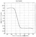
図1は、本発明のレンズの一方側の表面度数の連続的なグラデーションの一例を示す。表面度数は、レンズの他方側の光学度数への寄与が無いと想定した時の、所定の表面の曲率及び曲率の変化に応じて増加する光学度数として規定される。連続的な度数グラデーションを有する表面は、レンズの外面又は内面のいずれかとすることができる。図1は、好ましくは典型的にレンズの外面、言い換えれば前面に使用される本発明に係る面を例示する。この表面に亘る鉛直プロファイルに沿う距離をx軸上にプロットする。便宜上、この一例の直径60mmのレンズの面の最上縁部を30mmと規定し、レンズの中心を通る0−180線を0、そして最下縁部を−30mmとして示す。より大きな又はより小さなレンズ面も同様の方法で形成・プロットすることができる。y軸には、この一例の面における、レンズ上端部の3ディオプターの表面度数からレンズ下端部の5ディオプターの表面度数への度数グラデーションが示されており、この図において面の下方への2ディオプターの度数の線形増加に対応している。他の範囲の度数グラデーションも本発明の範囲に含まれることは自明である。好適な範囲には、レンズ面全体に亘る約0.5Dの増加からレンズ面全体に亘る約15ディオプターの度数増加までの連続的なグラデーションが含まれる。より好適な範囲には、レンズ面全体に亘って度数が約0.5Dだけ増加する連続的な度数グラデーションから、レンズ面全体に亘って表面度数が約8Dだけ増加するグラデーションまでが含まれる。(これらの範囲は、60mmのレンズ直径を想定しており、従って、より大きな又はより小さなレンズに応じて増減する)。なお、先行技術とは対照的に、該レンズ面は略一定な又は安定した度数の水平域を示さない。また、表面度数は、不連続性も変曲点も無く増加する。 FIG. 1 shows an example of a continuous gradation of surface power on one side of the lens of the present invention. The surface power is defined as an optical power that increases in accordance with a predetermined surface curvature and a change in curvature when it is assumed that there is no contribution to the optical power on the other side of the lens. The surface with a continuous power gradation can be either the outer surface or the inner surface of the lens. FIG. 1 illustrates the surface according to the present invention, which is typically used on the outer surface of the lens, in other words the front surface. The distance along the vertical profile across this surface is plotted on the x-axis. For convenience, the uppermost edge of the surface of this example 60 mm diameter lens is defined as 30 mm, the 0-180 line passing through the center of the lens is shown as 0, and the lowermost edge is shown as -30 mm. Larger or smaller lens surfaces can be formed and plotted in a similar manner. The y-axis shows a power gradation from the surface power of 3 diopters at the upper end of the lens to the surface power of 5 diopters at the lower end of the lens in this example surface. In this figure, 2 diopters below the surface are shown. Corresponds to a linear increase in frequency. It is obvious that other ranges of frequency gradation are also included in the scope of the present invention. Suitable ranges include a continuous gradation from an increase of about 0.5D over the entire lens surface to a power increase of about 15 diopters over the entire lens surface. A more suitable range includes from a continuous power gradation where the power increases by about 0.5D over the entire lens surface to a gradation where the surface power increases by about 8D over the entire lens surface. (These ranges assume a lens diameter of 60 mm and thus scale up or down depending on larger or smaller lenses). Note that, in contrast to the prior art, the lens surface does not exhibit a substantially constant or stable frequency horizontal range. Also, the surface power increases without discontinuities and inflection points.
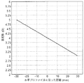
比較のために、標準的な前面累進レンズ面(先行技術)における老眼視の典型的な視線にプロットした度数プロファイルを図2に示す。また、便宜上且つ比較を容易にするために、この先行技術のレンズの最上縁部を30mmとして規定する。視線は、0と印をつけた距離においてレンズの0−180軸を横断し、−30mmの位置のレンズ下端部に達する。このプロットのy軸は、この典型的な累進レンズにおける光学度数の累進を示し、上端部近傍の約6.5Dからレンズ面の下端部近傍の約8.5Dまでの、2Dの公称加入度数が与えられる。このプロットは、約30mmと約5mmとの間におけるレンズ上端部近傍の略一定かつ安定な低度数(遠方視領域)の水平域と、その後の短距離の中間区域の度数の急激な上昇と、約−12mm未満の位置からレンズの下端部に延在する、レンズ下端部近傍の近方視領域のための略一定且つ高い安定光学度数の他の水平域とを明確に示している。これらの水平域は、完全に均一ではないが、平均安定値前後の変化の受容可能な範囲内に収まる。このように小さい度数変化は、光学設計及び実際の製造上の制約のために、安定度数領域において一般的なものである。また、水平域の間には明らかに変曲点が存在する。図1と比較すると、先行技術が本発明の度数グラデーション面とは明らかに且つ顕著に異なることが示される。 For comparison, a power profile plotted on a typical line of sight of presbyopia on a standard anterior progressive lens surface (prior art) is shown in FIG. For convenience and ease of comparison, the uppermost edge of this prior art lens is defined as 30 mm. The line of sight traverses the 0-180 axis of the lens at the distance marked 0 and reaches the lower end of the lens at a position of -30 mm. The y-axis of this plot shows the optical power progression in this typical progressive lens, with a nominal addition power of 2D from about 6.5D near the upper end to about 8.5D near the lower end of the lens surface. Given. This plot shows a substantially constant and stable low power (far vision region) horizontal region near the upper end of the lens between about 30 mm and about 5 mm, followed by a sharp increase in power in the short intermediate region, It clearly shows another horizontal region of approximately constant and high stable optical power for the near vision region in the vicinity of the lower end of the lens extending from a position less than about −12 mm to the lower end of the lens. These horizontal areas are not perfectly uniform but fall within an acceptable range of changes around the average stable value. Such small power variations are common in the stability power region due to optical design and actual manufacturing constraints. There is also an inflection point between the horizontal areas. Comparison with FIG. 1 shows that the prior art is clearly and significantly different from the power gradation surface of the present invention.
図1の度数グラデーションは、様々な開始曲率を有するレンズに具体化することができる。例えば、2ディオプターだけ増加する連続的な度数グラデーションを、公称球面曲率がレンズ上端部において1ディオプター、レンズ下端部において3ディオプターの本発明に係るレンズ面上に実現できる。2ディオプターの連続的な度数グラデーションは、レンズ上端部において6ディオプター、レンズ下端部において8ディオプターの公称球面曲率のレンズにも実現できる。第1の例は、高マイナスの遠方視矯正の処方により適しており、第2の例は、高プラスの処方により適したレンズを提供する。このことは、特にレンズ外面に設置した時の本発明の度数グラデーション面の他の利点も示す。つまり、任意の処方に対して、より平坦且つより審美的に好ましい基本曲線を選択することができる。この度数グラデーションによって、表面全体を球状にすることなく、外面に追加の必要な度数の一部がすでに設けられている。 The power gradation of FIG. 1 can be embodied in lenses with various starting curvatures. For example, a continuous power gradation increasing by 2 diopters can be realized on the lens surface according to the invention with a nominal spherical curvature of 1 diopter at the upper end of the lens and 3 diopters at the lower end of the lens. A continuous power gradation of 2 diopters can also be realized for a lens with a nominal spherical curvature of 6 diopters at the upper end of the lens and 8 diopters at the lower end of the lens. The first example is more suitable for a high-minus far vision correction prescription, and the second example provides a lens that is more suitable for a high-plus prescription. This also shows other advantages of the power gradation surface of the present invention, especially when installed on the lens outer surface. In other words, a basic curve that is flatter and more aesthetically favorable can be selected for any prescription. This power gradation already provides some additional power required on the outer surface without making the entire surface spherical.
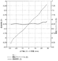
図1に、ディオプトリー度数の線形増加を示す。但し、レンズ面に亘る連続的な度数グラデーションのための他の関係を採用することは明らかに本発明の範囲内である。例えばほんの数例を挙げると、指数関数的、対数的、対数スパイラル的、若しくは二次関数的な正の度数又は他の非線形増加関係を使用することができる。レンズ面の上端部から下端部への度数グラデーションを有する非線形関係の一例を図3に示す。この度数プロファイルのプロットは、レンズの上部と比べて下部において度数がより急速に増加している(すなわち、表面に亘ってより短い距離変化でより早く度数が増加している)が、表面の曲線は滑らか且つ連続的で、安定光学領域に見られるような水平域を示していないことを示している。レンズの下端部に向かって曲率がより急速に増加するような非線形関係を採用する度数グラデーション面は、老眼処方において特に有利である。 FIG. 1 shows a linear increase in diopter power. However, it is clearly within the scope of the present invention to employ other relationships for continuous power gradation across the lens surface. For example, to name just a few, exponential, logarithmic, logarithmic spiral, or quadratic positive power or other non-linear increasing relationships can be used. An example of a non-linear relationship having a frequency gradation from the upper end to the lower end of the lens surface is shown in FIG. This power profile plot shows that the power increases more rapidly at the bottom than at the top of the lens (ie, the power increases faster with a shorter distance change across the surface), but the surface curve Indicates smooth and continuous and does not show the horizontal range as seen in the stable optical region. A power gradation surface that employs a non-linear relationship such that the curvature increases more rapidly toward the lower end of the lens is particularly advantageous in presbyopia prescriptions.
これらの多様な非限定の例示から、本発明によれば様々な連続的な度数グラデーション面を作成することができることは明らかである。この面の主な特徴は、不連続性や変曲点の無い、光学的に利用可能なレンズ面の略全体に亘る度数の漸進的且つ連続的な増加である。 From these various non-limiting examples, it is clear that various continuous power gradation surfaces can be created according to the present invention. The main feature of this surface is a gradual and continuous increase in power over almost the entire optically available lens surface without discontinuities or inflection points.
好適な実施例において、連続的な度数グラデーション面は、光学的に利用できない周囲余白部を有するレンズ面として構成してもよい。同様に、レンズの一部分又は部分的な余白部が光学的に利用できないように構成してもよい。このような部分や余白部は、例えば、レンズの周縁部を薄くするため、又は、移行の処理(他のレンズ面の仕上げや、コーティング、着色、或いはレンズの物理特性の変更等)のためにレンズを保持若しくは配向させるための補助として備えることができる。本発明では、連続的な度数グラデーションがこのレンズの光学設計における必須要素であり、この面がどのように構成されるかにかかわらず、レンズ面の利用可能な光学領域を説明するものとして認識する。 In a preferred embodiment, the continuous power gradation surface may be configured as a lens surface having a surrounding margin that is not optically available. Similarly, it may be configured such that a part or a partial margin of the lens cannot be used optically. Such a portion or blank portion is used, for example, for thinning the peripheral portion of the lens, or for transition processing (finishing of other lens surfaces, coating, coloring, or changing physical characteristics of the lens). It can be provided as an aid to hold or orient the lens. In the present invention, continuous power gradation is an essential element in the optical design of this lens, and is recognized as describing the available optical area of the lens surface, regardless of how this surface is constructed. .
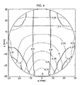
このことは、図4を参照することによってより容易に理解できよう。図4は、図1に例示するレンズ面の二次元図であるが、ディオプトリーの度数が前の値から所定の度数割合だけ漸進的に変化する距離ごとに等高線を引いた表面度数マップとして示す。増加量0.25Dの球面度数の変化を細線で示し、円柱度数の変化(増加量0.5D)を太実線で示す。各等高線と関連付けられた度数変化をその線上に示す。球面度数の値は、この例示するレンズ面の下端部における5Dに向けて増加する上端部における基本レンズ曲率度数3Dに対して相対的に表されている。円柱度数は、この例示の面において、主要な度数グラデーションの中央線に沿って低く、レンズを横断するx方向に沿ってほんのわずかに増加する。従って、x軸のプラス方向及びマイナス方向における第1の等高線が0.5Dとして示されている。この面は図1に示すような度数の連続的なグラデーションを具体化しているため、これらの線が度数の段階的な変化ではなく、漸進的な増加が記載の値を越える位置を単に示すということを念頭に置いて頂きたい。 This can be more easily understood with reference to FIG. FIG. 4 is a two-dimensional view of the lens surface illustrated in FIG. 1 and is shown as a surface power map in which contour lines are drawn for each distance at which the diopter power gradually changes from the previous value by a predetermined power ratio. A change in spherical power with an increase of 0.25D is indicated by a thin line, and a change in cylindrical power (increase of 0.5D) is indicated by a thick solid line. The frequency change associated with each contour line is shown on that line. The value of the spherical power is expressed relative to the basic lens curvature power 3D at the upper end portion that increases toward 5D at the lower end portion of the illustrated lens surface. The cylinder power is low along the center line of the main power gradation in this exemplary plane and increases only slightly along the x-direction across the lens. Therefore, the first contour line in the positive and negative directions of the x-axis is shown as 0.5D. This surface embodies a continuous gradation of frequencies as shown in FIG. 1, so that these lines are not gradual changes in frequency, but simply indicate where the incremental increase exceeds the stated value. I want you to keep that in mind.
なお、度数等高線は、レンズ表面の直径のうち広範な領域に亘って延在している。これらの等高線は、レンズ面に亘る2ディオプターの球面度数の広く前進的な増加を例示する一方、円柱度数はレンズの側部に向かって最小限の値だけ増加している。これは、連続的な度数グラデーションが主に球面度数の増加である一例であって、本発明の一好適な実施例である。例えば、第2面のデジタル処理が着用者の処方を決める際に重要な役割を果たす場合、一面上のこのような広く連続的な度数グラデーションは、幅広い処方に極めて適合可能であり、効果的に最終Rxを形成するのに使用できる。 The power contour line extends over a wide area of the diameter of the lens surface. These contour lines illustrate a wide and progressive increase in the diopter spherical power of 2 diopters across the lens surface, while the cylindrical power increases by a minimal value towards the side of the lens. This is an example in which the continuous power gradation is mainly an increase in spherical power, and is a preferred embodiment of the present invention. For example, if digital processing on the second side plays an important role in determining a wearer's prescription, such a wide continuous power gradation on one side can be very well adapted to a wide range of prescriptions and effectively Can be used to form the final Rx.
当業者であれば、図1及び4から、本発明の連続的な度数グラデーション面が、米国特許第2878721号等の先行技術特許や、図2の先行技術例に例示されるように度数変化がレンズの限定且つ制御された領域に限定され、(遠方視及び近方視用の)安定度数領域が最大化される他の特許及び設計からは区別されることが分かるであろう。 Those skilled in the art will understand from FIGS. 1 and 4 that the continuous frequency gradation surface of the present invention has a frequency change as illustrated in the prior art patents such as US Pat. No. 2,878,721 and the prior art example of FIG. It will be appreciated that the invention is distinguished from other patents and designs that are limited to limited and controlled areas of the lens and where the stability number area (for far vision and near vision) is maximized.
この連続的な度数グラデーションの手法によって、使用者に応じてレンズをカスタマイズする際の自由度が極めて高くなる。例えば、近方視領域及び遠方視領域が本発明のレンズ面によって予め規定されていないため、着用者に適合するようにそのサイズや位置を移動させたり調節したりすることができる。これは、外面の設計上のオフセットによって近方視領域又は遠方視領域の大きさが著しく減少しうる標準的な累進面セミフィニッシュレンズブランクに対して非常に有利である。同様に、本発明の連続的な度数グラデーションは、所定の領域を安定度数を維持するような制約が無いため、レンズ面の設計歪みによって起こる望ましくない非点収差が少ない。従って、本発明の漸進的な設計によって、どの隣接する増加間の変化もより均一に分布させることができるため、相対的な非点収差がどの領域においても少ない。 This continuous power gradation method gives a very high degree of freedom when customizing the lens according to the user. For example, since the near vision region and the far vision region are not preliminarily defined by the lens surface of the present invention, the size and position thereof can be moved or adjusted to suit the wearer. This is very advantageous over standard progressive surface semi-finished lens blanks where the size of the near or far vision area can be significantly reduced due to the design offset of the outer surface. Similarly, the continuous power gradation of the present invention is free from unwanted astigmatism caused by the design distortion of the lens surface because there is no restriction to maintain the stability power in a predetermined area. Thus, the incremental design of the present invention allows the change between any adjacent increases to be more evenly distributed, so there is less relative astigmatism in any region.
また、この連続的な度数グラデーションの発明によって、球面レンズブランクや、裏面累進表面加工との組み合わせで使用されることの多い点回転/軸回転対称非球面単焦点レンズブランクを使用する場合と比較して、より高い設計自由度が提供される。第1に、この連続的な度数グラデーション面と現代のデジタル表面加工技術とによって、加入度数を2つの面で共有して美的外観を最適化できる。第2に、加入度数を2つの面で共有するこの技術によって、連続的な度数グラデーション面が、累進レンズ上のように狭い領域に限定されるのではなくレンズの略全体に亘って延在するため、より大きな視野を得ることが可能になる。第3に、連続的な度数グラデーションを有するレンズ面がレンズの加入度数要件に積極的に寄与することによって、球面又は非球面単焦点レンズブランクに対する設計工学上の利点が得られる。この度数グラデーション面の度数への寄与によって実現される設計上の利点の例としては、より薄い(従ってより軽い)レンズ、レンズフレームの前後におけるレンズ厚さのより良好な分布、より幅広い処方範囲の収容(基本曲線の制約による制限が少ないため)、眼の動きや使用特性等の個人の好みに対するより容易なカスタム設計、レンズ全体に亘る処方度数の位置決めとフレームラップ、フレーム角又は傾きに関する実際のレンズ構成(その寸法特性)との両方の最適化が挙げられる。 In addition, this continuous power gradation invention is compared to the use of spherical lens blanks and point rotation / axis rotationally symmetric aspherical single focus lens blanks that are often used in combination with back surface progressive surface processing. Thus, a higher degree of design freedom is provided. First, with this continuous power gradation surface and modern digital surface processing technology, the addition power can be shared between the two surfaces to optimize the aesthetic appearance. Second, with this technique of sharing add power between the two surfaces, a continuous power gradation surface extends over substantially the entire lens rather than being limited to a narrow area as on a progressive lens. Therefore, a larger field of view can be obtained. Third, the lens surface with a continuous power gradation positively contributes to the power addition requirements of the lens, thereby providing design engineering advantages over spherical or aspheric single focus lens blanks. Examples of design benefits realized by the power contribution of this power gradation surface include thinner (and therefore lighter) lenses, better distribution of lens thickness before and after the lens frame, wider prescription range Containment (because there are less restrictions due to basic curve constraints), easier custom design for personal preference such as eye movement and usage characteristics, positioning of prescription power across the lens and frame wrap, actual angle of frame angle or tilt Optimization of both the lens configuration (its dimensional characteristics) can be mentioned.
本発明の他の利点は、同じ連続的な度数グラデーション面を有するレンズを使用して、設計要件や使用者の好みに応じて幅広い加入度数を形成することができるということである。これは、光学研究所や処方製造業者にとって有益である。何故なら、彼らには、出発レンズブランクほど多くの或いは多様な在庫は必要ないからである。例えば、レンズの外面に亘って2ディオプターの度数増加を有する本発明のレンズを使用し、加入度数が3ディオプターの完成レンズを所望する場合、内面を合計が3ディオプターとなるように設計できるとともに、本発明によって以下の2つの利点を実現することができる。1)外面が、3加入度数レンズの典型的な前面のように球状にならない。2)内面が、3加入度数レンズの典型的な内面のように平坦にならず、頬に対してより良好なクリアランスを設けることができる。或いは、本発明に係る同じレンズ面を使用して、1ディオプターの加入度数領域を有する完成レンズを製造することもできる。この場合、レンズは、内面の一部に逆進性を有し、(頬骨が突出しているような)ある種の顔形状に対して、また、近接してラップされた眼鏡フレームと共に使用する際に有利となる。更に他の例として、完成レンズに2ディオプターの加入度数が必要な場合、この加入度数のほとんどは、連続的な度数グラデーションを有するレンズ面に既に存在している。従って、他方の面は、度数を選択された最終加入度数領域の近傍にわずかに増補するだけでよく、異なる度数領域の安定化等の光学矯正における他の要素やレンズの審美的考慮のために主に使用することができる。 Another advantage of the present invention is that lenses having the same continuous power gradation surface can be used to form a wide range of powers depending on design requirements and user preferences. This is beneficial for optical laboratories and prescription manufacturers. This is because they do not need as much or as much inventory as the starting lens blank. For example, if a lens of the present invention having a power increase of 2 diopters across the outer surface of the lens is desired and a finished lens with a diopter of 3 diopters is desired, the inner surface can be designed to total 3 diopters, The following two advantages can be realized by the present invention. 1) The outer surface does not become spherical like the typical front surface of a 3 add power lens. 2) The inner surface is not as flat as the typical inner surface of a 3 add power lens and can provide better clearance for the cheek. Alternatively, the same lens surface according to the present invention can be used to produce a finished lens having an add power region of 1 diopter. In this case, the lens is reversible on a part of its inner surface and is used for certain face shapes (such as the cheekbone protruding) and when used with closely wrapped eyeglass frames. Is advantageous. As yet another example, if the finished lens requires a diopter power of 2 diopters, most of this power is already present on the lens surface with a continuous power gradation. Therefore, the other surface only needs to slightly augment the power in the vicinity of the selected final power region, for aesthetic considerations of other elements and lenses in optical corrections such as stabilization of different power regions. Can be used mainly.
また、異なる処方や使用者の好みに対応するために、本発明の度数グラデーション面の異なる部分を使用することも可能である。例えば、基本曲率をレンズ上端部で2D、レンズ下端部で6Dとして、レンズ全体に亘る合計の度数増加が4ディオプター、又は、30mm幅に亘る増加が2Dとなるような別の線形度数グラデーション面を考えよう。多くの小さいフレームは、その高さ寸法が20〜30mmの範囲である。従って、フレームの位置をレンズ面に対して上下に移動させて異なる基本曲線部分に対応させることができる。これは、レンズの曲率を選択的に処方要件に適合させるとともに、レンズを出来るだけ平坦な或いは審美的にバランスのとれたものに維持する助けになる。 It is also possible to use different portions of the power gradation surface of the present invention to accommodate different prescriptions and user preferences. For example, if the basic curvature is 2D at the upper end of the lens and 6D at the lower end of the lens, the total power increase over the entire lens is 4 diopters, or another linear power gradation surface where the increase over the 30 mm width is 2D. let's think. Many small frames have a height dimension in the range of 20-30 mm. Therefore, the position of the frame can be moved up and down with respect to the lens surface to correspond to different basic curve portions. This helps to selectively adapt the lens curvature to prescription requirements and keep the lens as flat or aesthetically balanced as possible.
或いは、異なる度数グラデーション範囲又は連続的な度数グラデーションを表す異なる関係を有するレンズ面を、異なる加入度数要件に対して選択し、レンズの他方の面と組み合わせて使用することによって、性能や審美性を最適化できる。このような設計上の自由度は、完成レンズを出来るだけ薄いものに維持しようとする場合に特に有益である。レンズは薄ければ薄いほど、より快適に着用(軽量化)できるとともに外観上もより魅力的なものとなる。 Alternatively, lens surfaces with different relationships representing different power gradation ranges or continuous power gradations can be selected for different power addition requirements and used in combination with the other surface of the lens for performance and aesthetics. Can be optimized. This design freedom is particularly beneficial when trying to keep the finished lens as thin as possible. The thinner the lens, the more comfortable it can be worn (weight reduction) and the more attractive the appearance.
本発明は、厚さバランスにおいて明確な利点を提供する。連続的な度数グラデーション面とそれと協働する第2レンズ面とを使用することによって、標準的な累進設計と比べ、より小さい非点収差が周縁部に寄せられる。また、加入度数を2つの面で共有するため、表面が一面設計のように顕著に突出することもない。同様に、レンズの下端部に向かって度数が連続的に増加する外面の好適な場合において、レンズ下方の有効な基本曲線の増加によって自動的に内面と外面との間のレンズ厚さのバランスが取れる。 The present invention provides a distinct advantage in thickness balance. By using a continuous power gradation surface and a cooperating second lens surface, less astigmatism is brought to the periphery compared to a standard progressive design. In addition, since the addition power is shared by the two surfaces, the surface does not protrude significantly unlike the one-surface design. Similarly, in the preferred case of an outer surface where the power increases continuously toward the lower end of the lens, the increase in the effective basic curve below the lens automatically balances the lens thickness between the inner and outer surfaces. I can take it.
本発明の連続的な度数グラデーションをレンズ面の略全体の領域において下方へ連続的に増加する度数として具体化する場合に、他の実際上の利点が老眼処方に対して発生する。レンズ面の下方へ連続的に増加する曲率のおかげで、レンズを通した中心視が主に、例えば裏面累進設計において見られるように表面に対してより傾斜した角度のものではなく垂直なものとして得られる。これは、より正確な式を使用して、非常に変化し易い傾斜視により起こる誤差を少なくして、最適な処方設計を計算及び設計できるということを意味する。また、垂直な位置付けのために、標準的なレンズメータによる測定処方と使用する実際の処方との間の差が少なくなる。これは、調整した処方を患者にとって確実に正確なものとしたい光学調整技術者(optical dispenser)にとって、極めて重要な考慮事項である。多くの現代の裏面累進設計では、大きく傾斜した視野角によって標準のレンズメータの読み取り値に1ディオプターに近い誤差が入ってしまうため、レンズ製造者は、正確な処方に対応していると製造者が確信を持てる代わりの読み取り値を調整技術者に提供しなければならない。明らかにこれは多くの場合、調整技術者にとって完成したレンズの正確性を確認するための実際的な手段がないため、安心できるものではない。 Another practical advantage arises for presbyopia prescriptions when the continuous power gradation of the present invention is embodied as a power that increases continuously downward in substantially the entire area of the lens surface. Thanks to the continuously increasing curvature below the lens surface, the central view through the lens is mainly perpendicular to the surface rather than at a more inclined angle as seen, for example, in the back progressive design can get. This means that more accurate formulas can be used to calculate and design an optimal recipe design with less error caused by highly variable tilting. Also, due to the vertical positioning, the difference between the standard lens meter measurement recipe and the actual recipe used is reduced. This is a very important consideration for an optical dispenser who wants to ensure that the adjusted prescription is accurate for the patient. In many modern back-end progressive designs, the lens manufacturer is advised that the correct prescription is supported because the angle of the viewing angle can introduce an error close to 1 diopter in standard lens meter readings. Must provide the adjustment technician with an alternative reading that he can be confident of. Obviously this is often not reassuring for the adjustment engineer because there is no practical means to check the accuracy of the finished lens.
以上説明し且つ前述の図面で例示してきた連続的な度数グラデーション面は、完成レンズの下端部近傍により高い光学度数が望まれるレンズの前面(外面)として使用するのに特に適している。これは、老眼を処置する標準的な構成に該度数グラデーション面を位置付ける。当業者にとって、この連続的な度数グラデーション面を、度数がレンズの下端部から上端部に漸進的に増加するように構成してもよいことは明らかであろう。このような構成は、例えば、オーバーヘッドディスプレイを読む必要のある航空機パイロットや整備士等の場合に有用である。 The continuous power gradation surface described above and illustrated in the previous drawings is particularly suitable for use as the front surface (outer surface) of a lens where higher optical power is desired near the lower end of the finished lens. This positions the power gradation surface in a standard configuration for treating presbyopia. It will be apparent to those skilled in the art that this continuous power gradation surface may be configured such that the power progressively increases from the lower end of the lens to the upper end. Such a configuration is useful, for example, for aircraft pilots or mechanics who need to read an overhead display.
他の実施例において、連続的な度数グラデーション面は、使用者の眼に近いレンズの内面に位置付けることができる。この構成において、度数グラデーション面は、好ましくは、レンズの上端部において、内面の下端部よりも小さい曲率半径を有する。そして、位置付けが内面(ネガティブ)のために、老眼処方での標準的な使用の領域において、このレンズ面の下端部においてより高い度数を提供する。しかしながら、レンズ設計に対して逆進的な手法を使用することを選択する場合には、レンズ下端部において上端部よりも小さい曲率半径を有する度数グラデーションの内側面を使用してもよい。 In other embodiments, a continuous power gradation surface can be located on the inner surface of the lens close to the user's eye. In this configuration, the power gradation surface preferably has a smaller radius of curvature at the upper end of the lens than at the lower end of the inner surface. And because the positioning is internal (negative), it provides higher power at the lower end of this lens surface in the area of standard use in presbyopia prescription. However, if one chooses to use a regressive approach to lens design, a power gradation inner surface with a smaller radius of curvature at the lower end of the lens than at the upper end may be used.
本発明の更に他の実施例において、連続的な度数グラデーションプロファイルは、(レンズ周縁厚さ等の)美的外観を向上したり、最も視野の明るくなるゾーンを広げたり、軸ずれを減らしたりするために、単焦点矯正に使用してもよい。多くの場合、人々は下方を見ながら近傍の作業を行う。度数グラデーションレンズ設計に基づく改良された視野角によって、全ての視野角がレンズの垂直切片に対してより密接に近接し、視野を最大化して、単焦点の着用者の場合でもより快適な視覚を作り出す。またこれによって、レンズ性能のより正確なモデリングが可能となり、従って、完成レンズをより良好に最適化することが可能になる。このことは、斜角視による誤差がより顕著になる場合、例えば、高度数矯正の場合や、ラップ型フレームにおける処方の場合において特に有利である。 In yet another embodiment of the present invention, the continuous power gradation profile improves aesthetic appearance (such as lens perimeter thickness), widens the zone with the brightest field of view, or reduces axial misalignment. In addition, it may be used for single focus correction. In many cases, people work nearby while looking down. Improved viewing angle based on the power gradient lens design, all viewing angles are closer to the lens's vertical section, maximizing the field of view and even more comfortable for single focus wearers produce. This also allows for a more accurate modeling of the lens performance and thus allows the finished lens to be better optimized. This is particularly advantageous when the error due to oblique viewing becomes more prominent, for example, in the case of altitude correction or prescription in a wrap frame.
ラップ型フレームで光学性能やレンズ外観を向上させる様々な実践方法が文献に記載されている。例えば、米国特許第6364481号では、プリズム度数を変化させて、特に光学ゾーンからこめかみに向かう周辺ゾーンまでレンズを横断するプリズムの水平成分のみを低下させることが注目されている。これは、周辺に向かう拡張ゾーンに追加の光学矯正を含めることによって明瞭な光学領域を増やすように設計されている。米国特許第6454408号にも、ラップ型フレームのためのレンズ設計の改良が記載されており、ここでは、両面の曲率変化が各面の対応する点において概ね等しくなるような「共変化面」を採用している。好適な面は径方向に対称であり、曲率の変化によって、好ましくは、度数がレンズに亘って水平に変化する。米国特許第6364481号と同様に、米国特許第6454408号では、視覚固定領域と称される中央視ゾーンが最適化され、こめかみに向かう拡張ゾーンが記載されている。 Various practical methods for improving optical performance and lens appearance with a wrap frame are described in the literature. For example, in US Pat. No. 6,364,481, attention is focused on changing the prism power to reduce only the horizontal component of the prism that traverses the lens, particularly from the optical zone to the peripheral zone toward the temple. It is designed to increase the clear optical area by including additional optical corrections in the extended zone towards the periphery. U.S. Pat. No. 6,454,408 also describes an improvement in lens design for a wrap frame, in which a “covariant surface” is used where the curvature changes on both sides are approximately equal at corresponding points on each side. Adopted. The preferred surface is symmetric in the radial direction, and the change in curvature preferably causes the power to change horizontally across the lens. Similar to U.S. Pat. No. 6,364,481, U.S. Pat. No. 6,454,408 optimizes the central viewing zone, referred to as the visual fixation area, and describes an expansion zone towards the temple.
本発明は、有用な更に他の態様で構成することができる。本実施例において、連続的な度数グラデーションは、レンズの上端部から下端部に増加するのではなく、該レンズの幅方向に増加する。この配向を、度数グラデーションのレンズ面の面等高線プロットとして図5に例示する。この面等高線プロットは、レンズ面の鼻側(x=30mm)からこめかみ側(x=−30mm)に向かって光学度数が2Dだけ増加する。個人の処方に合わせた他方の面のデジタル表面加工で、プリズムに加えて度数グラデーションの増加によって、追加的な条件に対処できる。例えば、レンズの外側周縁に向かって増加する曲率は、特により高度数の処方のしっかりとラップされたフレームに有用である。標準的な単焦点セミフィニッシュレンズブランク、特に高マイナス処方に適切なものに多く見られる問題として、平坦すぎるため大きく湾曲したラップフレームに嵌めることができないということがある。従って、フレームの水平曲線に合わせて曲率(度数)が増加する連続的な度数グラデーションを有するレンズとすることによって、この状況を改善できる。他の利点としては、レンズの曲率がこめかみ側の側縁部に向かって「ラップ」してレンズ度数を眼に対してより垂直に存在させることが可能になるため、この表面構成によっても斜角視を減らすことができるということがある。 The invention can be configured in yet another useful manner. In this embodiment, the continuous power gradation does not increase from the upper end to the lower end of the lens but increases in the width direction of the lens. This orientation is illustrated in FIG. 5 as a surface contour plot of a power gradation lens surface. In this surface contour plot, the optical power increases by 2D from the nose side (x = 30 mm) to the temple side (x = -30 mm) of the lens surface. With digital surface processing on the other side tailored to the individual's prescription, additional conditions can be addressed by increasing the power gradation in addition to the prism. For example, increasing curvature towards the outer periphery of the lens is particularly useful for tightly wrapped frames of higher numbers of prescriptions. A common problem with standard single focus semi-finished lens blanks, particularly those suitable for high minus prescriptions, is that they are too flat to fit into a large curved wrap frame. Therefore, this situation can be improved by using a lens having a continuous power gradation in which the curvature (frequency) increases in accordance with the horizontal curve of the frame. Another advantage is that this surface configuration also allows the lens curvature to “wrap” towards the side edge of the temple and allow the lens power to be more perpendicular to the eye. Sometimes it can reduce vision.
図5には基本曲率の3Dから5Dへの増加を例示として示すが、他の連続的な度数グラデーション及び他の基本曲線の範囲も本発明の範囲内である。そして、レンズの他方の面を、(例えば単焦点処方用に)少なくとも1つの有効な安定光学度数領域が形成されるように、或いは、多焦点処方用に遠方視又は近方視用の1つ以上の有効な安定領域が形成されるように、度数グラデーションを補うよう表面加工する。連続的な度数グラデーション設計の独自性のために、所定の処方を実現するための他方の面における対応する変化は、「共変化面」とは異なる変化を必要とする。 FIG. 5 shows by way of example the increase in basic curvature from 3D to 5D, but other continuous power gradations and other basic curve ranges are also within the scope of the present invention. The other surface of the lens is then formed so that at least one effective stable optical power region is formed (eg for a single focus prescription) or one for distance vision or near vision for multifocal prescription. Surface treatment is performed to compensate for the frequency gradation so that the above-described effective stable region is formed. Due to the uniqueness of the continuous power gradation design, the corresponding change in the other face to achieve a given prescription requires a different change from the “co-change face”.
他の実施例において、連続的な度数グラデーションの増加は、球面度数の増加の代わりに又はそれに加えて、円柱度数の増加を含んでもよい。円柱度数の小さい漸進的な増加は、図4及び5における度数グラデーション面の前述の例に見られる。幾つかの例において、これは、レンズ面の制約のために、計画された球面度数グラデーションとの関連で発生し得る。しかしながら、主に円柱度数グラデーションのために、又は円柱度数増加の制御された量のために、本発明のこの面を設計するように選択してもよい。これは、単焦点処方に対して特に有利であり、また、ラップ型フレーム、特にこめかみ側近傍において顕著な屈曲を有するものに対して有用である。この円柱度数グラデーションの好適な実施例は、鉛直軸に対して線形増加するものである。 In other embodiments, the continuous power gradation increase may include a cylindrical power increase instead of or in addition to the spherical power increase. A small gradual increase in cylinder power can be seen in the previous example of the power gradation surface in FIGS. In some examples, this can occur in the context of a planned spherical power gradation due to lens surface constraints. However, one may choose to design this aspect of the present invention primarily for a cylindrical power gradation or for a controlled amount of cylindrical power increase. This is particularly advantageous for single focus prescriptions and is useful for wrap frames, especially those with significant bends near the temple side. A preferred embodiment of this cylindrical power gradation is a linear increase with respect to the vertical axis.
連続的な度数グラデーションを有する面は、アンビリカル(umbilical)線を有して設計してもしなくてもよい。つまり、本発明は、選択された線上の任意の点において、水平曲率と鉛直曲率とが等しく、制御されたアンビリカル累進を形成するように具現化できる。本発明において、このアンビリカルは、(多くの累進レンズ面のようには)安定度数の2つの有効領域を接続せず、その代わりにレンズの利用可能な光学領域の一周縁から他周縁へ、漸進的且つ連続的に増加する度数の線に沿って延在する。本実施例によれば、アンビリカル線の設計されるような球面特性のために、アンビリカルに沿うとともにその各側への望ましくない円柱度数が減少する。しかしながら、これは、アンビリカルから離間した位置に望ましくない円柱度数の増加を伴う。 Surfaces with continuous power gradations may or may not be designed with umbilical lines. That is, the present invention can be implemented such that at any point on the selected line, the horizontal and vertical curvatures are equal and a controlled umbilical progression is formed. In the present invention, this umbilical does not connect the two effective areas of stability number (like many progressive lens surfaces), but instead progressives from one edge of the available optical area of the lens to the other. Extending along a line of increasing power continuously and continuously. According to this embodiment, because of the spherical characteristics as designed for the umbilical line, undesirable cylindrical power along the umbilical and on each side thereof is reduced. However, this is accompanied by an undesired increase in cylinder power at a location away from the umbilical.
一好適な実施例において、度数グラデーションのための長いアンビリカル線が、使用者の近用(読書)時の凝視動作に応じて位置付けられ、従って、鼻に向かって角度をつけやすい。或いは、アンビリカルは、伝統的な累進レンズとは異なる方向に向けることができる。例えば、アンビリカルに沿う度数グラデーションの増加を、レンズ上の0−180軸(水平軸)に配向させてもよい。本実施例は、ラップフレームに対して特に有用である。アンビリカル線を有する度数グラデーションは、レンズ面を横断する他の角度で位置付けることによって、様々なフレーム形状や個々人の処方に適応させることができる。 In one preferred embodiment, a long umbilical line for power gradation is positioned in response to the user's near-eye (reading) gaze movement, and is therefore easy to angle towards the nose. Alternatively, the umbilical can be oriented in a different direction than a traditional progressive lens. For example, the power gradation increase along the umbilical may be oriented on the 0-180 axis (horizontal axis) on the lens. This embodiment is particularly useful for wrap frames. Power gradations with umbilical lines can be adapted to various frame shapes and individual prescriptions by positioning them at other angles across the lens surface.
他の好適な実施例は、アンビリカル線を有さない連続的な度数グラデーション面を使用する。この場合、表面上の幾つかの離散点が水平方向及び鉛直方向に等しい曲率を有してもよいが、垂直配向における等しい曲率の連続線は画成されない。従って、任意のどの点においても、表面は水平方向及び鉛直方向に異なる曲率を有してもよい。先行技術において、単焦点レンズ用の円柱状又は環状(トロイダル)面は既知である(例えば米国特許第6935744号及び第7399080号を参照)が、これらの手法は、光学的に利用可能なレンズ面全体に亘る連続的かつ漸進的な度数増加を組み込んでいない。累進レンズ設計及び単焦点レンズのいずれも、本発明とは対照的に安定光学度数の広い領域を具現化している。 Another preferred embodiment uses a continuous power gradation surface with no umbilical lines. In this case, some discrete points on the surface may have equal curvature in the horizontal and vertical directions, but a continuous line of equal curvature in the vertical orientation is not defined. Thus, at any given point, the surface may have different curvatures in the horizontal and vertical directions. In the prior art, cylindrical or toroidal surfaces for single focus lenses are known (see for example US Pat. Nos. 6,935,744 and 7,399,080), but these techniques are optically available lens surfaces. It does not incorporate continuous and gradual power increase throughout. Both progressive lens designs and single focus lenses embody a wide range of stable optical power, in contrast to the present invention.
アンビリカル線を有さない連続的な度数グラデーション面は、アンビリカル線を有する同様の面よりも最大の不要円柱度数が低い。これは、制約される線が無く純粋な球状となるためである。これは、アンビリカルを有する面と同じ光学矯正を実現するための他面に必要な不要円柱度数の矯正が少なくて済むためであり、言い換えれば、必要な矯正が小さいのでより良好な最適化が行なうことができるためである。また、性能のための画成された線が無いため、2つの面の間の配向、横方向の位置付け及び最適化の自由度がより高い。従って、アンビリカル線を有さない選択肢は、度数グラデーション面の有利な実施例である。 A continuous power gradation surface having no umbilical line has a lower maximum unnecessary cylinder power than a similar surface having an umbilical line. This is because there is no constrained line and it is a pure sphere. This is because the correction of unnecessary cylindrical power required for the other surface for realizing the same optical correction as the surface having the umbilical is small, in other words, the necessary correction is small, so that better optimization is performed. Because it can. Also, since there are no defined lines for performance, there is a greater degree of freedom in orientation between the two faces, lateral positioning and optimization. Thus, the option of not having an umbilical line is an advantageous embodiment of a power gradation surface.
次に、度数グラデーション面の実施例を、レンズの他面と組み合わせることによって、所望の処方を作成し、安定光学度数の有効領域を少なくとも1つ有する完成レンズを提供する。好ましくは、遠方視及び近方視値を有する処方用に、本発明のレンズ面の組み合わせによって、安定光学度数の領域を少なくとも2つ設ける。より好ましくは、2つの領域のうち1つを遠方視用に作成し、もう1つを近方視用に作成する。より好ましくは、作成された安定光学度数の2つの領域を有効領域とする。 The power gradation surface embodiment is then combined with the other surface of the lens to create the desired prescription and provide a finished lens having at least one effective area of stable optical power. Preferably, for a prescription having far vision and near vision values, at least two regions of stable optical power are provided by the combination of the lens surfaces of the present invention. More preferably, one of the two regions is created for far vision and the other is created for near vision. More preferably, the two regions having the stable optical power thus created are effective regions.
任意ではあるが、2つの面の組み合わせには、美的外観や個々の使用者の好みや実際の使い方、製造の容易さ、及び光学性能の最適化等の他の要素を考慮に入れてもよい。使用者の好みとしては、例えば、レンズ上の遠方視領域と近方視領域との間の物理的距離や、遠方視領域及び近方視領域の大きさ、視野領域内及び周辺において許容できる円柱度数(非点収差)の量、遠方視領域と近方視領域との間の好適な凝視角といった要素や、着用者の活動や習慣に基づく他の要素が挙げられる。これら及び同様の要素は、異なる重要度で、設計又は最適化の一連の作業に振り分けることができる。 Optionally, the combination of the two surfaces may take into account other factors such as aesthetic appearance, individual user preferences and practical usage, ease of manufacture, and optimization of optical performance. . As a user's preference, for example, a physical distance between the far vision region and the near vision region on the lens, the size of the far vision region and the near vision region, and a cylinder that can be allowed in and around the viewing region. Factors such as the amount of power (astigmatism), a suitable gaze angle between the far vision region and the near vision region, and other factors based on the wearer's activity and habits. These and similar elements can be assigned to a series of design or optimization tasks with different importance.
処方を受け取ると、連続的な度数グラデーション面を先験的に選択してレンズを完成させてもよいし、或いは、レンズがどのように使用されるかに関して追加情報を収集してもよい。本発明の他の利点は、あらゆる度数グラデーション面を幅広い種類の処方に適用させる自由度が増すということである。例えば、レンズ面の下方に2ディオプターだけ増加する線形度数グラデーションを考えよう。この面は、他面の独自の数学的設計と組み合わせて様々な方法で使用できる。それにより、様々な遠方視矯正を組み込みつつ、加入度数が+2ディオプターのレンズや、加入度数が+1ディオプター(他面によって度数が差し引かれた)のレンズ、加入度数が+3ディオプター(他面によって度数が追加された)のレンズ、並びに中間の加入度数を作成できる。同様に、度数グラデーション面は遠距離度数及び加入度数の小さい領域に制約されないので、最終の処方の結果の遠方視領域及び近方視領域を広げたり、水平方向にオフセットさせたり、鉛直方向に再位置付けしたりするように、他面を設計することができる。 Upon receipt of the prescription, a continuous power gradation surface may be selected a priori to complete the lens, or additional information may be collected regarding how the lens is used. Another advantage of the present invention is that it provides more freedom to apply any power gradation surface to a wide variety of prescriptions. For example, consider a linear power gradation that increases by 2 diopters below the lens surface. This surface can be used in various ways in combination with the original mathematical design of the other surface. It incorporates various distance vision corrections, a lens with a diopter of +2 diopters, a lens with a diopter of +1 diopter (power deducted by the other side), and a diopter of +3 diopter (power by the other side) Added) as well as intermediate add powers. Similarly, the power gradation surface is not constrained by regions with a small distance power and addition power, so the far vision region and the near vision region as a result of the final prescription are widened, offset in the horizontal direction, or reverted in the vertical direction. The other side can be designed to be positioned.
異なる例において、度数グラデーションの増加がレンズ下方に向かうのではなくラップ型のレンズを横断するように、レンズの配向を変更してもよい。そして外面は、処方のために必要であれば加入度数領域を作成するように、或いはと組み合わせて単焦点矯正を施すように適応させることができる。先に述べたように、レンズを横断する度数グラデーションによって、ラップ型でも明瞭な視野領域をより広く形成するように外面を設計し易くなる。この最適化された視野領域は、度数グラデーションの増加によって補助され、その度数グラデーションの増加は、ラップ曲率により良好に調和してレンズ面をどの視線方向に対してもより垂直になるように選択することができる。他の例において、使用者の近用(読書用)の特定の凝視角が既知の場合、度数グラデーションの増加を、その面の度数増加をより完璧に利用するために、(単に鉛直に位置付けるのではなく)その角度に配列させてもよい。 In a different example, the orientation of the lens may be changed so that the power gradation increases across the wrap lens rather than down the lens. The outer surface can then be adapted to create an add power region if necessary for prescription or in combination with a single focus correction. As described above, the power gradation that crosses the lens makes it easier to design the outer surface so as to form a clear visual field region even with a wrap type. This optimized field of view is aided by an increase in power gradation that selects the lens surface to be more perpendicular to any line-of-sight direction in a better harmony with the wrap curvature. be able to. In another example, if the specific gaze angle of the user's near-field (reading) is known, the power gradient increase can be simply (positioned vertically) in order to more fully utilize the power increase of the face (But not at that angle).
或いは、様々な要素に応じて、異なる連続的な度数グラデーション面を選択してもよい。例えば、より小さいフレームに対して、図3に示すようなより急峻な度数増加又は非線形増加が好ましいことが考えられる。他の例において、フレームと顔との間に十分な余地がある場合には、審美性を向上させるために、より多くの加入度数がレンズの内面に載置されるようなグラデーションを選択してもよい。高プラス又は高マイナス遠方視処方の場合、レンズを薄くしたりフレームの前後においてレンズの厚さのバランスをとったりするために、異なる開始レンズ曲率の、又は増加度数の異なる総合程度の、度数グラデーションを選択してもよい。フレーム設計、並びに、とりわけ、前傾角、顔形状又はラップ角、瞳孔距離、及び角膜頂間距離等の装着要素に応じて、異なる度数グラデーションの増加、度数グラデーションを表す異なる数学的関係、又は表面の異なる基本曲率を選択してもよい。アンビリカル線を有する連続的な度数グラデーション面は、不要円柱度数に対して極めて敏感な人に好適であり、アンビリカル線を有さない(従って、面を横断してより分配された全体の不要円柱度数が低い)度数グラデーション面は、加入度数要件が限られた初期の老視患者に好適である。また、最終処方を作成するために余分な材料をどれだけ他面から除去する必要があるか、完成レンズの必要な特徴を作成するのがどれだけ難しいかといった製造要素を考慮に入れてもよい。例えば、最終の近方視度数が遠方視矯正よりも4ディオプター強い必要がある場合、外面によって加入度数の優位性が提供され度数グラデーション面を使用する有効な利点が低下してしまいうるため、たった0〜0.50ディオプターの度数増加を有する度数グラデーション面を選択することはあまりない。しかしこれらは数少ない例であり、当業者であれば、本発明の範囲内で考慮すべき他の有利な選択肢を認識するであろう。 Alternatively, different continuous power gradation surfaces may be selected depending on various factors. For example, it is conceivable that a steeper frequency increase or non-linear increase as shown in FIG. 3 is preferable for smaller frames. In another example, if there is sufficient room between the frame and the face, select a gradation that allows more addition power to be placed on the inner surface of the lens to improve aesthetics. Also good. For high plus or high minus far vision prescriptions, power gradients with different starting lens curvatures or different degrees of increase are used to thin the lens and balance the lens thickness before and after the frame. You may choose. Depending on the frame design and, among other things, the anteversion angle, face shape or lap angle, pupil distance, and intercorneal distance, an increase in different power gradations, different mathematical relationships representing power gradations, or surface Different basic curvatures may be selected. A continuous power gradation surface with umbilical lines is suitable for people who are extremely sensitive to unwanted cylinder power and does not have umbilical lines (thus the total unwanted cylinder power more distributed across the surface). A power gradation surface is suitable for early presbyopic patients with limited power requirements. You may also take into account manufacturing factors such as how much extra material needs to be removed from the other side to create the final prescription, and how difficult it is to create the required features of the finished lens. . For example, if the final near diopter power needs to be 4 diopters stronger than the far vision correction, the outer surface provides the advantage of add power and may reduce the effective advantage of using the power gradation surface. It is rare to select a power gradation surface with a power increase from 0 to 0.50 diopters. However, these are only a few examples and those skilled in the art will recognize other advantageous options to consider within the scope of the present invention.
連続的な度数グラデーション面を選択したら、他面を、第1面との組み合わせによって所望の処方を生じさせ完成レンズに少なくとも1つの有効安定光学度数領域が形成されるように計算する。連続的な度数グラデーション面は、既知の1つ以上の等式によって表されるか、xyz座標の固有の組み合わせによって表現される。そして、最終処方及び考慮すべき他の要素に伴う、度数グラデーション面の等式又は値を、他面並びに2つの面の組み合わせを画成及び最適化するための一連の計算作業に入力する。これは、レイトレーシング、波面伝播分析、曲率計算、若しくはこれらの又は他の技術の組み合わせ等、多くの既知の技術によって実現できる。そしてこの計算を使用して、CNC機械等の表面加工設備の運転をプログラム又は指示して、両面を所望の値に成形する。 Once a continuous power gradation surface has been selected, the other surface is calculated in combination with the first surface to produce the desired prescription and form at least one effective stable optical power region in the finished lens. A continuous power gradation surface is represented by one or more known equations or represented by a unique combination of xyz coordinates. The frequency gradation surface equations or values associated with the final recipe and other factors to be considered are then entered into a series of computation operations to define and optimize the other surface and the combination of the two surfaces. This can be accomplished by many known techniques such as ray tracing, wavefront propagation analysis, curvature calculation, or a combination of these or other techniques. Then, using this calculation, the operation of the surface processing equipment such as a CNC machine is programmed or instructed to form both sides to a desired value.
上記議論を通じて全般的に、連続的な度数グラデーション面を、レンズブランクの一面、内面又は外面に度数グラデーションを具現化し、光学度数のためにそれ以上の変更は施していないセミフィニッシュブランクとして説明してきた。技術水準のデジタル表面加工機械の多くは、外面をそれ以上加工する必要のないセミフィニッシュレンズブランクを最も容易に収容し、内面をこの機械によって切削又は「仕上げ」して最終の形状及び表面品質を得る。これは非常に実際的で好適な実施例であるが、本発明をブランクの両側を表面加工する、つまり、一面を所望の連続的な度数グラデーション面の等式又はxyz座標に従って切削し、他面を切削し該度数グラデーション面と組み合わせることにより最終処方を作成することで実現することができることが理解できよう。この手法は、一連の追加の切削工程を必要とするが、セミフィニッシュ度数グラデーションブランクのストックを維持する必要が無いという選択肢を提供する。これら全ての選択肢は、本発明の範囲内である。 Throughout the discussion above, we have generally described a continuous power gradation surface as a semi-finished blank that embodies a power gradation on one, inner or outer surface of the lens blank and has no further changes due to optical power. . Many state-of-the-art digital surface processing machines most easily accommodate semi-finished lens blanks that do not require further processing of the outer surface, and the inner surface is cut or “finished” by this machine to achieve the final shape and surface quality. obtain. This is a very practical and preferred embodiment, but the present invention surfaces both sides of the blank, i.e. cuts one side according to the desired continuous power gradation surface equation or xyz coordinates, It will be understood that this can be realized by cutting and combining with the power gradation surface to create the final prescription. This approach offers the option of requiring a series of additional cutting steps but not having to maintain a stock of semi-finished frequency gradation blanks. All these options are within the scope of the present invention.
これらの追加の変形例及び他の構成は、全ての可能な実施例を包含するものではないが、当業者であれば本発明の様々な実施例の範囲に含まれるものであると理解するだろう更なる例を提供する。 These additional variations and other configurations do not encompass all possible embodiments, but those skilled in the art will appreciate that they are within the scope of the various embodiments of the present invention. A further example of wax is provided.
本発明を、以下の非限定の例を参照してより詳細に説明する。 The invention will now be described in more detail with reference to the following non-limiting examples.
これらの例の幾つかは、有効加入度数を呈するレンズを用いて遠方視及び近方視のための矯正処方を作成する本発明の実施例を説明するものである。眼科用レンズ産業において、(公称加入度数−0.125D)、(公称加入度数−0.25D)、少なくとも75%の加入度数、及び少なくとも85%の加入度数等の加入度数領域を画成するための方法は複数ある。以下の例において、適用可能な場合、90%の加入度数(例えば、2D加入度数レンズの場合は0.90×2=1.8D)という控え目ではあるが例示的な画成を使用する。 Some of these examples illustrate embodiments of the present invention that create corrective prescriptions for far vision and near vision using lenses that exhibit effective add power. In the ophthalmic lens industry to define add power areas such as (nominal add power—0.125 D), (nominal add power—0.25 D), at least 75% add power, and at least 85% add power. There are multiple methods. In the following example, a modest but exemplary definition of 90% add power (eg, 0.90 × 2 = 1.8D for a 2D add power lens) is used where applicable.
例1
遠方視矯正が0ディオプターで加入度数が+2ディオプターの本発明に係るレンズを設計することを目標とした。便宜上、このレンズは、標準的な累進レンズのレイアウトと同様に、レンズ上部に遠方視矯正を、レンズの下端部近傍に加入度数を有するように設計した。以下の標準フィッティングパラメーターを計算に使用した:目の角膜からレンズ裏面の頂点までの距離(角膜頂間距離):13mm;近方視領域の変位:鼻側に2mm;レンズの0−180線から完全加入度数値までの距離:16mm;前傾角:8度;ラップ角:5度。
Example 1
The goal was to design a lens according to the invention with a distance vision correction of 0 diopters and an add power of +2 diopters. For convenience, this lens was designed to have distance vision correction at the top of the lens and add power near the bottom of the lens, similar to a standard progressive lens layout. The following standard fitting parameters were used in the calculation: distance from the cornea of the eye to the apex of the back of the lens (corneal apex distance): 13 mm; displacement of the near vision region: 2 mm to the nose side; from the 0-180 line of the lens Distance to complete addition value: 16 mm; forward tilt angle: 8 degrees; lap angle: 5 degrees.
図1及び4に示す面を、完成レンズ前側の連続的な度数グラデーション面として使用した。この面は、ワイアント‐クリース方式(Wyant−Creath scheme)に従って整理される150直交ゼルニケ多項式の合計として数学的にモデリングされ、この面表現の係数を、処方されたレンズ計算の入力とした。計算は、度数グラデーション面に関する情報とフィッティングパラメーターとを組み合わせて、処方要件を満たすのに必要なレンズ他面の特徴を決定する正確なレイトレーシングを介して行なった。これらの計算のために、レンズ他面(これらの例ではレンズ裏面)を、150ゼルニケ多項式の別の展開式によって表わした。レンズ裏面の展開式の係数を、計算の任意の段階における実際の度数マップを理論度数マップと比較するメリット関数の最小化によって求めた。最適化は、BFGS(ブロイデンーフレッチャーゴールドファーブーシャンノ(Broyden−Fletcher−Goldfarb−Shanno))最適化アルゴリズムを用いて行なった。 The surface shown in FIGS. 1 and 4 was used as a continuous power gradation surface on the front side of the finished lens. This surface was mathematically modeled as a sum of 150 orthogonal Zernike polynomials arranged according to the Wyant-Creath scheme, and the coefficients of this surface representation were used as input for the prescribed lens calculation. The calculation was done through accurate ray tracing that combines information about the power gradation surface and fitting parameters to determine the characteristics of the other lens surface necessary to meet the prescription requirements. For these calculations, the other lens surface (the lens back surface in these examples) was represented by another expansion formula of 150 Zernike polynomials. The coefficient of the expansion formula on the back side of the lens was obtained by minimizing the merit function that compares the actual power map with the theoretical power map at any stage of the calculation. Optimization was performed using the BFGS (Broiden-Fletcher-Goldfarb-Shanno) optimization algorithm.
図6は、この処方要件を満たす図4に例示するレンズ面と組み合わせるために計算された裏面の面等高線マップを示す。この例において、図6は、レンズの内面となるように設計されたものである。なお、この内面は、相当量の円柱度数を示し、円柱度数は下方面に亘って急速に変化している(太線の等高線)が、球面度数(細線の等高線)の変化はずっと小さい。 FIG. 6 shows a back surface contour map calculated for combination with the lens surface illustrated in FIG. 4 that satisfies this prescription requirement. In this example, FIG. 6 is designed to be the inner surface of the lens. The inner surface shows a considerable amount of cylindrical power, and the cylindrical power changes rapidly over the lower surface (thick contour lines), but the change in spherical power (thin contour lines) is much smaller.
図7は、図6の面を図4の度数グラデーション面と組み合わせた場合の計算された透過度数の等高線のプロットを示す。このプロットは、レンズを介して見た時に知覚される有効光学度数を示す。太線は円柱度数値を表し、細線は球面度数の等高線を示す。加入度数領域は、1.8Dの球面度数の等高線によって示され、所望加入度数の少なくとも90%の光学度数を有する領域に対応している。図7は、2つの面の組み合わせによって、ゼロ矯正(プラノ度数(plano power))の遠方視用の大きな安定光学度数領域と、光学度数が急峻に変化する中間帯域と、加入度数領域用の約+2ディオプターの安定光学度数を有する他の領域とを有するレンズが作成されることを示す。 FIG. 7 shows a plot of the calculated transmittance contours when the surface of FIG. 6 is combined with the frequency gradation surface of FIG. This plot shows the effective optical power perceived when viewed through the lens. A thick line represents a cylindrical degree value, and a thin line represents a contour line of spherical power. The addition power region is indicated by a 1.8D spherical power contour and corresponds to a region having an optical power of at least 90% of the desired power addition. FIG. 7 shows the combination of the two planes, a large stable optical power range for far vision with zero correction (plano power), an intermediate band where the optical power changes sharply, and an approximate power for the power range. It shows that a lens with +2 diopter stable optical power and other regions is made.
このレンズを他の方法で分析すると、図8は、レンズの上端部からレンズの下端部への典型的な老眼視線に追従し、本例のレンズの結果の中間帯域及び加入度数領域を通過するプロファイルに沿う計算された度数を示す。破線は、このレンズの裏面に沿うこの位置的プロファイルを、右側軸上に示す関連する表面度数値と共にトレースしている。実線は、完成レンズの同じ位置的プロファイルを、左側軸上に示すこのレンズのために計算された透過度数の値と共にトレースしている。 When this lens is analyzed in other ways, FIG. 8 follows a typical presbyopic line of sight from the upper end of the lens to the lower end of the lens and passes through the resulting midband and add power region of the lens of this example. Indicates the calculated frequency along the profile. The dashed line traces this positional profile along the back of the lens, with the associated surface power value shown on the right axis. The solid line traces the same positional profile of the finished lens with the transmittance value calculated for this lens shown on the left axis.
図8の、完成レンズの透過度数をトレースしている実線で示すプロファイルは、完成レンズにおいて、光学度数の2つの安定領域が、図1及び4に例示するレンズ前面と、図6及び8(破線プロット)に例示するレンズ裏面との組み合わせによって作成されていることを示す。実線の透過度数は、約30mmから0mm近くに延在する遠方視処方のために必要な約0ディオプターの値を有する一領域と、度数が概ね2Dの−15mmから−30mmに他の領域を示す。両方の領域は度数の水平域として表れている。これらの領域は、平均度数が±0.06Dの安定領域の最も要求される好適な解像度に適合している。これら2つの領域における図7の等高線プロットを再検証すると、これら2つのレンズ面によって安定光学度数を有して形成される領域が、有効となるレンズ面に亘って十分な程度を有することが確認できる。従って、この例は、これらレンズ面の組み合わせによって光学度数の有効安定領域を作成することに成功している。 The profile indicated by the solid line tracing the transmission power of the completed lens in FIG. 8 is that the two stable regions of optical power are the front surface of the lens illustrated in FIGS. 1 and 4 and FIGS. (Plot) shows that it is created by a combination with the rear surface of the lens exemplified in FIG. Solid line transmission power shows one region with a value of about 0 diopters required for distance vision prescriptions extending from about 30 mm to close to 0 mm, and another region at -15 mm to -30 mm with a power of approximately 2D. . Both areas appear as frequency horizontals. These areas are compatible with the most required preferred resolution of stable areas with an average power of ± 0.06D. Reviewing the contour plots of FIG. 7 in these two regions confirms that the region formed by these two lens surfaces with a stable optical power has a sufficient extent across the effective lens surfaces. it can. Therefore, in this example, an effective stable region of optical power is successfully created by combining these lens surfaces.
また、図8の破線プロファイルは、所望の処方を提供するために前面の度数グラデーションと協働する裏面に要求される度数変化に驚くべきものがあることを示している。これは、複数の度数変化を有すると共に、このような変化がマイナス方向とプラス方向との両方に局地的に起こるレンズ面の独自で非直観的な形態である。 Also, the dashed line profile in FIG. 8 shows that there are surprising power changes required on the back side that cooperate with the front side power gradation to provide the desired prescription. This is a unique and non-intuitive form of the lens surface that has multiple power changes and such changes occur locally in both the negative and positive directions.
本発明の他の独自性は、所望の処方が、度数グラデーション面上の特定の安定度数領域又は水平域に依存せずに実現され、この面が最終の加入度数に顕著に寄与していたということである。これは、図1に示すような表面度数プロファイルのプロット上のy=−10とy=−30との間の表面度数の値を図8の破線と比較することによって見ることができる。この領域において、前面の表面度数(図1)は、約4.3Dから5Dに増加する。対照的に、裏面の表面度数は、まず−10mmと−15mmとの間において−3Dから約−2.65Dに減少し、約−2.9Dから−30mmまで再び増加する。これら2つの面の度数の加入度によって、レンズの結果となる加入度数が非常に粗く近似される。この場合、その加入度は、約(+4.3+−3)=1.3Dから(+5+−2.9)=2.1Dまでの範囲となる。これは、図8の実線によって例示されるより正確に計算された透過近用度数と調和しており、連続的な度数グラデーション面上に起こる表面度数の増加によって主に促進される、この領域において約1.35Dから2D近くに増加する加入度数を示している。また、図7及び8の完成レンズのデータを比較すると、図8の水平域領域が、この2つの異なるレンズ面の組み合わせによって完成レンズに対して形成される有効安定光学度数領域に対応していることが分かる。 Another uniqueness of the present invention is that the desired prescription was realized without depending on a specific stability power region or horizontal region on the power gradation surface, and this surface contributed significantly to the final addition power. That is. This can be seen by comparing the surface power value between y = −10 and y = −30 on the surface power profile plot as shown in FIG. 1 with the dashed line in FIG. In this region, the front surface power (FIG. 1) increases from about 4.3D to 5D. In contrast, the surface power of the back side first decreases from -3D to about -2.65D between -10mm and -15mm and increases again from about -2.9D to -30mm. The power addition of these two surfaces approximates the addition power resulting from the lens very roughly. In this case, the addition power ranges from about (+ 4.3 + −3) = 1.3D to (+ 5 + −2.9) = 2.1D. This is in harmony with the more accurately calculated transmission near power illustrated by the solid line in FIG. 8, in this region, which is mainly facilitated by the increase in surface power that occurs on the continuous power gradation surface. The addition power increases from about 1.35D to near 2D. Further, when comparing the data of the completed lens of FIGS. 7 and 8, the horizontal region of FIG. 8 corresponds to the effective stable optical power region formed for the completed lens by the combination of the two different lens surfaces. I understand that.
どのように本発明を使用して所定の処方又は着用者の好みや使用法に対してレンズの特性を調整するかを例示するために、2つの追加の例を提供する。遠方視矯正がゼロディオプターで加入度数が+2ディオプターの処方例を再び使用して、例2及び3並びに図9〜12によって、図1及び4に前面の例として例示した上記面をどのように様々な他面と組み合わせて、同じRxを有しつつ異なる光学特性又は使用者が望む特性を有するレンズを作成するかについて明らかにする。面を数学的に表現する方法及びこれらの例の最適化技術は、例1について使用したものと同じ手法である。 Two additional examples are provided to illustrate how the present invention can be used to adjust lens characteristics for a given prescription or wearer's preference and usage. Using the example of prescription with a distance diopter of zero diopter and a diopter of +2 diopter, how to use the above example illustrated in FIGS. 1 and 4 as an example of the anterior surface according to examples 2 and 3 and FIGS. In combination with various other surfaces, it will be clarified how to create a lens having the same Rx but different optical properties or properties desired by the user. The method of mathematically representing the surface and the optimization techniques in these examples are the same techniques used for Example 1.
例2
この例において、例1の場合と同様に、遠方視矯正が0ディオプターで加入度数が+2ディオプターの本発明に係るレンズを設計することを目標とした。ただし、この例では、遠方視領域と近方視領域との間の鉛直方向距離が例1のレンズよりも短いレンズとするという追加の制約を計算に含めた。この制約は、例えば、より小さなメガネフレームを選択する人や、読書位置に対応するための下方への目の移動が少ない人が望む。フィッティングパラメーターは、0−180線以下の完全加入度数までの距離を16mmの代わりに13mmに設定した以外は、例1において使用したものと同じである。
Example 2
In this example, as in Example 1, the objective was to design a lens according to the invention with a distance vision correction of 0 diopter and an add power of +2 diopter. However, in this example, an additional constraint that the distance in the vertical direction between the far vision region and the near vision region is shorter than the lens in Example 1 is included in the calculation. This restriction is desired, for example, by a person who selects a smaller eyeglass frame or a person who moves less eyes downward to accommodate the reading position. The fitting parameters are the same as those used in Example 1 except that the distance to the complete add power below the 0-180 line was set to 13 mm instead of 16 mm.
図9は、図8と同様に、レンズの上端部から下端部への典型的な老眼視線に追従し、レンズ裏面に亘る光学度数値(破線及び右側軸)と、例2の完成レンズの計算された透過度数の値(実線及び左側軸)とをトレースした計算された度数プロファイルを示す。本例の完成レンズの透過度数(図9における実線)は、処方において所望されるような2つの安定光学度数領域を示す。また、図8の透過度数プロファイルと、図9の透過度数プロファイルとを比較すると、約+2Dの加入度数を有する安定領域が図9によって例示されるレンズのプロファイルの下方に達する距離がより短いことが分かる。同じ度数グラデーション面(図1及び4に例示されるような)を、例1及び2の両方に使用した。従って、完成レンズ上において加入度数領域をより高い位置に移動するために、例2の裏面は、例1の裏面とは異なる度数寄与を有する必要がある。これは、図9における裏面のプロファイルトレース(破線)から分かる。−10mmの位置において、表面度数は(例1における−3Dと比較して)−2.5Dだけであり、従って、この裏面では、図8に例示したレンズ裏面よりも加入度数領域の上部において、前面の度数グラデーションから引かれる値が小さい。 FIG. 9 follows the typical presbyopic line of sight from the upper end to the lower end of the lens, as in FIG. 8, and the optical power values (dashed line and right axis) across the back of the lens and the calculation of the completed lens of Example 2. Figure 6 shows a calculated power profile traced with the measured power values (solid line and left axis). The transmission power of the finished lens of this example (solid line in FIG. 9) shows two stable optical power regions as desired in the prescription. Also, comparing the transmission power profile of FIG. 8 with the transmission power profile of FIG. 9, the distance that the stable region having an addition power of about + 2D reaches below the profile of the lens illustrated by FIG. 9 is shorter. I understand. The same power gradation surface (as illustrated in FIGS. 1 and 4) was used for both Examples 1 and 2. Therefore, in order to move the add power region to a higher position on the finished lens, the back surface of Example 2 needs to have a different power contribution than the back surface of Example 1. This can be seen from the profile trace (broken line) on the back surface in FIG. At the position of −10 mm, the surface power is only −2.5D (compared to −3D in Example 1), and therefore, on this back surface, in the upper part of the addition power region than the lens back surface illustrated in FIG. The value drawn from the front frequency gradation is small.
追加的な情報を提供するために、図10は、この例のレンズの期待される透過近用度数のための計算された度数等高線プロットを示す。1.8Dの球面度数の等高線によって囲まれた領域は、例1のレンズと比較して、明らかにレンズの中央側に更に広がっており、この面の組み合わせによって、有効安定加入度数領域へのより短い距離が実現できていることを示す。図10の透過近用度数等高線プロットにおいて、0.5Dの球面度数等高線及び円柱度数等高線の両方が、図7に示すものよりもプラスy方向に高い位置に表れていることに気がつくであろうが、この効果は、加入度数への距離が短い累進レンズに多く見られるものであり、且つ、例2に示すものよりもずっと顕著に表れうるものである。連続的な度数グラデーション面設計を使用する1つの利点としては、完成レンズにおける不要な度数の遠方視領域へのこのような進入を減少させるということが考えられる。同様に、図10の1.8D等高線によって画成される有効安定近方視領域が、例1の設計よりも大きいことに注意されたい。これは、レンズの度数グラデーション面と他面との組み合わせの最適化によって影響されうる他の変形を示す。 To provide additional information, FIG. 10 shows a calculated power contour plot for the expected transmission near power of the lens of this example. The region surrounded by the 1.8D spherical power contours clearly extends further toward the center of the lens compared to the lens of Example 1, and this combination of surfaces allows more effective addition to the stable power region. It shows that a short distance can be realized. In the transmission near power contour plot of FIG. 10, you will notice that both the 0.5D spherical power contour and the cylindrical power contour appear at higher positions in the plus y direction than those shown in FIG. This effect is often seen in progressive lenses with a short distance to add power, and can be much more pronounced than that shown in Example 2. One advantage of using a continuous power gradation surface design may be to reduce such entry to an unwanted power far vision region in the finished lens. Similarly, note that the effective stable near vision region defined by the 1.8D contour in FIG. 10 is larger than the design of Example 1. This represents another variation that can be influenced by optimizing the combination of the lens power gradation surface and the other surface.
例3
遠方視矯正がゼロディオプターで、加入度数が+2ディオプターの本発明に係る他のレンズを設計することを目標とした。フィッティングパラメーターは、例1において使用したものと同じとした。しかしこの例では、例1よりも広い近方視領域を有するレンズを作成するために、計算に別の要件を含めた。
Example 3
The goal was to design another lens according to the present invention with zero diopter for distance vision correction and +2 diopter power. The fitting parameters were the same as those used in Example 1. However, in this example, another requirement was included in the calculation to create a lens with a wider near vision region than in Example 1.
再び、この例のレンズの前面に、図1及び4に例示する度数グラデーション面を使用した。図11は、このレンズの上端部(30mm)から該レンズの下端部(−30mm)への老眼視の典型的な視線に沿う、レンズ裏面の表面度数プロファイル(破線及び右側軸)と、完成レンズの計算された透過度数(実線及び左側軸)とを示す。透過度数プロットは、ゼロディオプターの遠方視矯正及び+2Dの加入度数のための所望の安定光学度数領域を示す。この裏面プロファイルの形状は、前述の例におけるものと同様であるが、−10mmの位置において約−3.15Dの表面度数値を有しており、これは前述の例において観察されたものよりも大きい。また、裏面度数は、例1において使用された裏面よりもレンズの加入度数領域に亘ってわずかに変化している。 Again, the power gradation surface illustrated in FIGS. 1 and 4 was used on the front surface of the lens of this example. FIG. 11 shows the surface power profile (dashed line and right axis) on the back of the lens along the typical line of sight of presbyopia from the upper end (30 mm) of the lens to the lower end (−30 mm) of the lens, and the finished lens. The calculated transmittance numbers (solid line and left axis). The transmission power plot shows the desired stable optical power range for zero diopter distance vision correction and + 2D addition power. The shape of this back profile is similar to that in the previous example, but has a surface power value of about −3.15D at a position of −10 mm, which is more than that observed in the previous example. large. Further, the back surface power slightly changes over the addition power region of the lens as compared with the back surface used in Example 1.
このレンズに関連した計算されたプロット(図12)は、前述の例と同様、遠方視値のための安定度数の有効領域が大きく、且つ、例1のレンズ上の対応する領域よりも広い近方視の有効安定領域(1.8D等高線によって境界付けられる)を明らかに示している。この設計において、例2のように、0.5Dの球面度数(細線)及び円柱度数の等高線(太線)が、例1の場合よりもレンズ上方に延在しており、2Dの不要円柱度数等のより高い円柱近用領域がより大きい。しかし、例3ではより広くて大きい近方視‐遠方視領域が得られるため、このような設計のトレードオフは許容できる。 The calculated plot associated with this lens (FIG. 12), as in the previous example, has a larger effective range of stability numbers for distance vision values and a wider range than the corresponding region on the lens of Example 1. It clearly shows the effective stability area of the perspective (bounded by the 1.8D contour). In this design, as in Example 2, the spherical power (thin line) of 0.5D and the contour line (thick line) of the cylindrical power extend above the lens compared to the case of Example 1, and the unnecessary cylindrical power of 2D, etc. The higher cylinder near area is larger. However, since Example 3 provides a wider and larger near vision-far vision region, such a design trade-off is acceptable.
驚くべきことに、例1〜3において度数グラデーション面と組み合わせられる面は、標準的な単焦点面や累進面のいずれとも異なって見える。度数が増加又は減少する、レンズに亘る普通とは異なる度数変化及び複数の変化は上述したとおりである。多くの累進面は、レンズの遠方視領域における円柱度数を制限しようとするものであるが、この制限は例1〜3において使用される面には必要ない。例えば、図6においてプロットされる裏面度数マップは、0.5Dの円柱度数等高線(太線)によって境界付けられる狭い帯域と、0.5〜1.0Dによるレンズの上半分の大きい領域とを示している。しかしながら、図4に示すような面との組み合わせにおいて、図7に例示するように、完成レンズの結果として得られる遠方視領域を広げるのに役立てるために、レンズの対向面の円柱度数を使用できるということが分かる。本発明に係る連続的な度数グラデーション面と組み合わせられる対向面には他の利点がある。それらの円柱度数成分は、(累進レンズ面とは対照的に)レンズ面のより広範に亘るため、度数変化はより漸進的となり、従って、従来の表面加工又はデジタル表面加工のいずれかによって作成し易い。好適な実施例において、他面の略全体に亘る漸進的な変化が、連続的な度数グラデーション面と協働して、最終の処方を作成する。従って、本発明において、所望の組み合わせを作り出すために両面に革新的な構成を取り入れる必要があることが多いことは明らかである。 Surprisingly, the surface combined with the power gradation surface in Examples 1-3 looks different from either the standard single focal plane or the progressive surface. Unusual power changes and multiple changes across the lens where the power increases or decreases are as described above. Many progressive surfaces attempt to limit the cylindrical power in the distance vision region of the lens, but this limitation is not necessary for the surfaces used in Examples 1-3. For example, the back power map plotted in FIG. 6 shows a narrow band bounded by a 0.5D cylindrical power contour (thick line) and a large area in the upper half of the lens from 0.5 to 1.0D. Yes. However, in combination with the surface as shown in FIG. 4, the cylindrical power of the opposing surface of the lens can be used to help widen the far vision region resulting from the finished lens, as illustrated in FIG. I understand that. There are other advantages to the facing surface combined with the continuous power gradation surface according to the present invention. Since their cylindrical power components are more extensive of the lens surface (as opposed to a progressive lens surface), the power change is more gradual and therefore can be created by either conventional surface processing or digital surface processing. easy. In the preferred embodiment, a gradual change over substantially the entire other surface cooperates with the continuous power gradation surface to create the final recipe. It is therefore clear that in the present invention it is often necessary to incorporate innovative configurations on both sides to create the desired combination.
前述の例では、ある所定の処方のために本発明により実現することができる完成レンズ設計における変形例の幾つかを例示した。完成レンズ特性の幾つかの変形例は、その所定の加入度数の予め設定された領域及び遠方明瞭視領域のために、標準的な累進レンズブランクを用いて実現することが極めて難しい。連続的な度数グラデーション面によって、例1〜3に示すように、様々な設計要件又は使用者の好みに適応可能なより広い領域が提供できる。 The foregoing example illustrates some of the variations in the finished lens design that can be realized with the present invention for a given prescription. Some variations of the finished lens characteristics are extremely difficult to achieve with standard progressive lens blanks because of the predetermined add power pre-set region and far clear vision region. The continuous power gradation surface can provide a wider area that can be adapted to various design requirements or user preferences, as shown in Examples 1-3.
以下の例は、異なる処方を作成するために同じ連続的な度数グラデーション面をどのように使用できるかを例示する。 The following example illustrates how the same continuous power gradation surface can be used to create different recipes.
例4
この例において、図1及び4に例示する面をレンズ前面として使用し、更に他のレンズ裏面と組み合わせることによって、遠方視領域において−2ディオプターの矯正と近方視領域において+3ディオプターの加入度数とを有する本発明に係る完成レンズを提供した。面の数学的表現の形態及び最適化手法は時前述の例において使用したものと同じであり、例1のフィッティングパラメーターを使用した。図13は、これらの処方要件を実現するために度数グラデーション面と組み合わせられる裏面のための面等高線度数プロットを示す。このレンズ裏面は、前述の例よりも大きな円柱度数変化(太線の等高線)に加えて、高く急峻に変化する球面度数(細線の等高線)を示す。
Example 4
In this example, the surface illustrated in FIGS. 1 and 4 is used as the front surface of the lens and combined with the other back surface of the lens, thereby correcting -2 diopters in the far vision region and +3 diopters addition in the near vision region. A completed lens according to the present invention is provided. The form of the mathematical representation of the surface and the optimization technique were sometimes the same as those used in the previous examples, and the fitting parameters of Example 1 were used. FIG. 13 shows a surface contour power plot for the back surface combined with a power gradation surface to achieve these prescription requirements. The rear surface of the lens shows a spherical power (contour line of fine line) that changes high and steeply in addition to a larger change in cylindrical power (thick contour line) than in the above-described example.
図14は、この面の組み合わせによってこの例のレンズに期待される透過近用度数の計算された度数等高線プロットを示す。この面の組み合わせによって、レンズの上半分に、大きな有効安定遠方視領域が形成されており、−1.5Dの球面度数等高線と0.5Dの円柱度数限界とによって境界付けられている。この大きな領域は、処方される−2Dの値に近い光学度数を有する。これら2つの面を組み合わせることによって形成されるレンズの近方視領域は、0.7Dの球面度数等高線によって囲まれる。これは、加入度数が少なくとも+2.7D、又は期待される加入度数の90%に対応する(−2D遠方視Rx+2.7D近方視Rx=0.7D有効値)。 FIG. 14 shows a calculated power contour plot of the transmission near power expected for the lens of this example by this surface combination. This combination of surfaces forms a large effective stable distance vision region in the upper half of the lens, bounded by a -1.5D spherical power contour and a 0.5D cylindrical power limit. This large area has an optical power close to the prescribed -2D value. The near vision region of the lens formed by combining these two surfaces is surrounded by a 0.7D spherical power contour. This corresponds to a power addition of at least + 2.7D, or 90% of the expected power addition (−2D far vision Rx + 2.7D near vision Rx = 0.7D effective value).
このレンズの度数プロファイルを図15に示す。前述の例の場合のように、プロファイルは、レンズの上端部(30mm)で開始し、遠方視領域から近方視領域を通ってレンズの下端部(−30mm)まで老眼視線に沿って延在している。このレンズの計算された透過度数の実線によって、遠方視矯正のための−2Dの安定度数の水平域と、+3Dの加入度数要件に対応する近方視領域における約1Dの安定度数の他の水平域とが明示されている。図4の面と組み合わせられてこのレンズを形成する裏面は、前述の例と同様の普通とは異なる波状の度数プロファイルを示すが、異なる表面度数値及びより大きい相対変化を示す(図15の破線及び右側軸)。において最小度数を実現するために、裏面は、前述の例よりも大幅に大きな度数を提供し、前面の度数グラデーションの増加と協働するためにより急に変化する必要がある。同様に、裏面度数が−10mmから−30mmへのそのプロファイルに沿って前述の例よりも大きく変化し、この協働によって、いずれの面もそれ自身の有効安定領域を示すことなく2つの面が完成レンズにおいてより高く安定した加入度数領域を形成していることが分かるだろう。 The power profile of this lens is shown in FIG. As in the previous example, the profile starts at the upper end of the lens (30 mm) and extends along the presbyopic line of sight from the far vision region through the near vision region to the lower end of the lens (−30 mm). doing. The solid line of the calculated transmission power of this lens allows a horizontal area of -2D stability level for distance vision correction and other horizontal levels of stability of about 1D in the near vision area corresponding to the addition power requirement of + 3D. The area is specified. The back surface that forms this lens in combination with the surface of FIG. 4 shows an unusual wavy power profile similar to the previous example, but with different surface power values and larger relative changes (dashed line in FIG. 15). And right axis). In order to achieve the minimum power at, the back surface needs to change more rapidly to provide a power that is significantly greater than the previous example and to cooperate with the increase in the power frequency gradation on the front surface. Similarly, the back surface power varies much more than the previous example along its profile from -10 mm to -30 mm, and this cooperation allows the two surfaces to appear without any surface showing its own effective stability region. It can be seen that the finished lens forms a higher and more stable addition power region.
これらの計算は、単一の連続的なグラデーション面を様々な他の面と組み合わせる異なる方法の例を例示している。当業者であれば、1つの例示的な度数グラデーション面によって様々な処方及びレンズ特性を作成することができれば、他の度数グラデーション面をレンズの他方側に使用することによって同様に様々な異なる処方が可能になるとともに、様々な光学的、審美的、又は実際的な性能要素に対応することができることは理解されよう。 These calculations illustrate examples of different ways of combining a single continuous gradation surface with various other surfaces. If one skilled in the art can create various prescriptions and lens characteristics with one exemplary power gradation surface, then various different prescriptions can be obtained by using other power gradation surfaces on the other side of the lens as well. It will be appreciated that various optical, aesthetic, or practical performance factors can be accommodated as they become possible.
以下の例は、単焦点レンズのための連続的な度数グラデーション面の使用を例示する。 The following example illustrates the use of a continuous power gradation surface for a single focus lens.
例5
この例では、球面度数が−4.25D、円柱度数が+1D、及び円柱度数軸が180°の本発明に係るレンズを設計することを目標とした。このような処方は、かなり一般的ではあるが、通常プラス処方と関連付けられるより高い基本曲線が必要なことが多いラップフレームに適応させるのが特に難しい場合がある。連続的な度数グラデーション設計の1つの利点は、レンズ面の球面曲率をレンズ全体に亘って増加するように選択できることである。この特徴は、例えば、レンズをラップフレームに嵌める際に有利に使用できる。以下の標準フィッティングパラメーターを計算に使用した:眼の角膜からレンズ裏面の頂点までの距離(角膜頂間距離):13mm、フェースフレーム(ラップ)角:15度、及び前傾角:4度。前述の例において使用した面を数学的に表現する方法及び最適化手法を、例5においても使用した。
Example 5
In this example, the objective was to design a lens according to the present invention having a spherical power of −4.25D, a cylindrical power of + 1D, and a cylindrical power axis of 180 °. Such a prescription, although fairly common, can be particularly difficult to adapt to wrap frames that often require a higher base curve usually associated with a positive prescription. One advantage of a continuous power gradation design is that the spherical curvature of the lens surface can be selected to increase across the lens. This feature can be used advantageously, for example, when fitting a lens to a wrap frame. The following standard fitting parameters were used in the calculation: distance from the cornea of the eye to the apex of the back of the lens (corneal apex distance): 13 mm, face frame (lap) angle: 15 degrees, and anteversion angle: 4 degrees. The method of mathematically expressing and optimizing the surfaces used in the previous example was also used in Example 5.
この例では、図5に例示する連続的な度数グラデーション面をレンズの他面として使用した。なお、本発明のこの面においては、度数増加をレンズの上端部から下端部へ、ではなく、レンズの一側部から他側部へ横断させるようにした。図5における球面度数の等高線(細線)から分かるように、度数グラデーションの増加を、度数が0−180軸に沿ってこめかみ(−30mm)に向かって増加するように配列した。0−180軸に沿うこの面の度数プロファイルのプロットをトレースした図16から、図5に示す面が不連続性や変曲点を有さないことが確認できる。 In this example, the continuous power gradation surface illustrated in FIG. 5 was used as the other surface of the lens. In this aspect of the invention, the power increase is made to cross from one side of the lens to the other side rather than from the upper end to the lower end of the lens. As can be seen from the spherical power contours (thin lines) in FIG. 5, the power gradations were arranged so that the power increases along the 0-180 axis toward the temple (-30 mm). From the trace of the frequency profile plot of this surface along the 0-180 axis, it can be confirmed that the surface shown in FIG. 5 has no discontinuities or inflection points.
図17は、図5の連続的な度数グラデーション面と組み合わせて特定の単焦点処方を形成するレンズ裏面の表面度数等高線プロットを示す。この裏面は、該特定の処方における180°の円柱度数軸と調和する、前述の例とは異なる円柱度数分布を示す。また、この面上の球面度数の等高線(細線)は、より高マイナス面(より高い凹面)を描写し、これは所望のRxの−4.25Dの球面度数を収容するのに適している。 FIG. 17 shows a surface power contour plot of the back of the lens that forms a specific single focus prescription in combination with the continuous power gradation surface of FIG. This backside shows a different cylindrical power distribution than the previous example, in harmony with the 180 ° cylindrical power axis in the particular formulation. Also, the spherical power contours (thin lines) on this surface depict a higher minus surface (higher concave surface), which is suitable to accommodate the desired Rx -4.25D spherical power.
図18は、図5及び図17の面の組み合わせによって形成された例のレンズの計算された透過度数の値に対応する度数等高線プロットを示す。これら2つの面の協働によって、矯正球面度数及び円柱度数両方の処方値を有する非常に広範な領域が形成され、この領域は、レンズのこめかみ部分に向かってよく延在している(−y値)。 FIG. 18 shows a power contour plot corresponding to the calculated transmission power value of the example lens formed by the combination of the surfaces of FIGS. The cooperation of these two surfaces forms a very wide area with prescription values for both corrected spherical power and cylindrical power, which extends well towards the temple part of the lens (-y value).
このレンズに関して計算された度数プロファイルによって、これらの結果が確認できる。図19は、裏面の表面度数プロファイル(破線及び右側のy軸値)並びにレンズの計算された透過度数(実線及び左側のy軸値)をトレースしたものである。この例において、プロファイル線は、レンズの中央に位置付けられ(図18に示すようにy=0の位置)、レンズの鼻側縁部(30mm)からレンズのこめかみ側縁部(−30mm)まで延びている。透過度数プロファイルが、レンズ全体に亘る所望の処方に対して良好に同調し、安定光学度数の非常に大きな有効領域がこのレンズ面の組み合わせによって形成されていることを例示している。本例において、裏面度数プロファイル(図19の破線)は代替の連続的な度数グラデーション面と類似しており、図17に例示するその対応する等高線マップによって、この面が円柱度数値及び球面度数の顕著な変化を有していることが示されている。 These results can be confirmed by the power profile calculated for this lens. FIG. 19 is a trace of the surface power profile (broken line and right y-axis value) on the back surface and the calculated transmittance power (solid line and left y-axis value) of the lens. In this example, the profile line is located in the center of the lens (y = 0 position as shown in FIG. 18) and extends from the nose side edge (30 mm) of the lens to the temple side edge (−30 mm) of the lens. ing. The transmission power profile is well tuned for the desired prescription throughout the lens, illustrating that a very large effective area of stable optical power is formed by this lens surface combination. In this example, the back surface power profile (broken line in FIG. 19) is similar to an alternative continuous power gradation surface, and the corresponding contour map illustrated in FIG. It has been shown to have significant changes.
この例のレンズ上の矯正処方を有する広範な有効領域は、傾斜した角度で着用者に対してレンズの大部分を表し得るラップ型フレームの場合に、特に注目に値するとともに有利な設計である。この設計による、連続的な度数グラデーション面の加入曲率は、レンズ面のより大部分が眼に対して垂直となることを意味し、これによって、角度的な歪みの少ないより良好な視力矯正が可能になる。驚くべきことに、漸進的に増加する度数は単焦点ラップ型レンズには必要ないにもかかわらず、度数グラデーション面の使用によって、非常に好適な光学的解決手法が提供される。また、この良好に好適化された処方レンズは、ラップ型レンズで典型的に使用される急峻でより球状の基本曲線の代わりに、たった3〜5Dの範囲の前面基本曲線により実現される。 The wide effective area with the corrective prescription on the lens of this example is a particularly noteworthy and advantageous design in the case of a wrap frame that can represent the majority of the lens to the wearer at an inclined angle. With this design, the addition curvature of the continuous power gradation surface means that most of the lens surface is perpendicular to the eye, which allows better vision correction with less angular distortion become. Surprisingly, although a progressively increasing power is not necessary for a single focus wrap lens, the use of a power gradation surface provides a very suitable optical solution. This well-optimized prescription lens is also realized with a frontal basic curve in the range of only 3-5D instead of the steep and more spherical basic curve typically used in wrap-type lenses.
本発明を、好適な実施例、並びにこれらの実施例の複数の変形例や派生例を参照し詳細に開示してきたが、当業者であれば、追加の代替策、組み合わせ、変形が本発明の概念及び範囲から逸脱することなく可能であることは理解されよう。これら及び同様の変形例は、当業者にとって明細書及び図面を精査した後に明らかとなろう。従って、本発明は、以下の特許請求の範囲によって特定されるものである。 Although the present invention has been disclosed in detail with reference to preferred embodiments and multiple variations and derivatives of these embodiments, those skilled in the art will recognize additional alternatives, combinations, and variations of the present invention. It will be understood that this is possible without departing from the concept and scope. These and similar variations will become apparent to those skilled in the art after reviewing the specification and drawings. Accordingly, the invention is defined by the following claims.
Claims (14)
利用可能な光学領域を有する第1レンズ面と、前記第1レンズ面に対して前記レンズの反対側の第2レンズ面とを備え、
前記第1レンズ面が、前記利用可能な光学領域の略全体に亘る連続的且つ漸進的な光学度数の変化を有し、前記連続的且つ漸進的な光学度数の変化が、球面度数の変化を有し、
変曲点を有さず、且つ不連続性を有さず、前記利用可能な光学領域の一方の縁部から、前記利用可能な光学領域の反対側の縁部に向かって増加し、
前記第2レンズ面が、前記第1レンズ面と協働して、前記レンズが安定光学度数の少なくとも1つの第1有効領域を含んで前記所望の処方を提供するように構成されている眼科用レンズ。 An ophthalmic lens providing the desired prescription,
A first lens surface having an available optical area; and a second lens surface opposite to the lens with respect to the first lens surface;
The first lens surface has a continuous and gradual change in optical power over substantially the entire available optical area, and the continuous and gradual change in optical power causes a change in spherical power. Have
No inflection point and no discontinuity, increasing from one edge of the available optical region to the opposite edge of the available optical region;
The second lens surface is configured to cooperate with the first lens surface such that the lens includes at least one first effective area of stable optical power to provide the desired prescription. lens.
利用可能な光学領域を有する第1レンズ面と、前記第1レンズ面に対して前記レンズの反対側の第2レンズ面とを備え、
前記第1レンズ面が、前記利用可能な光学領域の略全体に亘る連続的且つ漸進的な光学度数の変化を有し、前記連続的且つ漸進的な光学度数の変化が、度数の線形増加を含み、変曲点を有さず、且つ不連続性を有さず、前記利用可能な光学領域の一方の縁部から、前記利用可能な光学領域の反対側の縁部に向かって増加し、
前記第2レンズ面が、前記第1レンズ面と協働して、前記レンズが遠方視用の安定光学度数の少なくとも1つの第1有効領域と近方視用の安定光学度数の少なくとも1つの第2有効領域とを含んで前記所望の処方を提供するように構成されている眼科用レンズ。 An ophthalmic lens for providing a desired prescription having both far vision and near vision values,
A first lens surface having an available optical area; and a second lens surface opposite to the lens with respect to the first lens surface;
The first lens surface has a continuous and gradual change in optical power over substantially the entire available optical area, and the continuous and gradual change in optical power results in a linear increase in power. Including no inflection point and no discontinuity, increasing from one edge of the available optical region to an opposite edge of the available optical region;
The second lens surface cooperates with the first lens surface so that the lens has at least one first effective area of a stable optical power for far vision and at least one first optical power of a stable optical power for near vision. An ophthalmic lens configured to provide the desired prescription including two effective areas.
利用可能な光学領域を有する第1レンズ面と、前記第1レンズ面に対して前記レンズの反対側の第2レンズ面とを備え、
前記第1レンズ面が、前記利用可能な光学領域の略全体に亘る連続的且つ漸進的な光学度数の変化を有し、前記連続的且つ漸進的な光学度数の変化が、度数の非線形増加を含み、変曲点を有さず、且つ不連続性を有さず、前記利用可能な光学領域の一方の縁部から、前記利用可能な光学領域の反対側の縁部に向かって増加し、
前記第2レンズ面が、前記第1レンズ面と協働して、前記レンズが遠方視用の安定光学度数の少なくとも1つの第1有効領域と近方視用の安定光学度数の少なくとも1つの第2有効領域とを含んで前記所望の処方を提供するように構成されている眼科用レンズ。 An ophthalmic lens for providing a desired prescription having both far vision and near vision values,
A first lens surface having an available optical area; and a second lens surface opposite to the lens with respect to the first lens surface;
The first lens surface has a continuous and gradual change in optical power over substantially the entire available optical area, and the continuous and gradual change in optical power causes a non-linear increase in power. Including no inflection point and no discontinuity, increasing from one edge of the available optical region to an opposite edge of the available optical region;
The second lens surface cooperates with the first lens surface so that the lens has at least one first effective area of a stable optical power for far vision and at least one first optical power of a stable optical power for near vision. An ophthalmic lens configured to provide the desired prescription including two effective areas.
Applications Claiming Priority (3)
| Application Number | Priority Date | Filing Date | Title |
|---|---|---|---|
| US12/697,060 US8042941B2 (en) | 2010-01-29 | 2010-01-29 | Lens with continuous power gradation |
| US12/697,060 | 2010-01-29 | ||
| PCT/US2010/050986 WO2011093929A1 (en) | 2010-01-29 | 2010-09-30 | Lens with continuous power gradation |
Publications (3)
| Publication Number | Publication Date |
|---|---|
| JP2013518309A JP2013518309A (en) | 2013-05-20 |
| JP2013518309A5 JP2013518309A5 (en) | 2013-11-21 |
| JP5856080B2 true JP5856080B2 (en) | 2016-02-09 |
Family
ID=43033251
Family Applications (1)
| Application Number | Title | Priority Date | Filing Date |
|---|---|---|---|
| JP2012551146A Active JP5856080B2 (en) | 2010-01-29 | 2010-09-30 | Lens with continuous power gradation |
Country Status (8)
| Country | Link |
|---|---|
| US (1) | US8042941B2 (en) |
| EP (1) | EP2529270B1 (en) |
| JP (1) | JP5856080B2 (en) |
| CN (1) | CN102741735B (en) |
| BR (1) | BR112012018978B1 (en) |
| CA (1) | CA2785885C (en) |
| ES (1) | ES2582452T3 (en) |
| WO (1) | WO2011093929A1 (en) |
Families Citing this family (24)
| Publication number | Priority date | Publication date | Assignee | Title |
|---|---|---|---|---|
| JP5789108B2 (en) * | 2011-03-08 | 2015-10-07 | イーエイチエス レンズ フィリピン インク | Progressive power lens and design method thereof |
| JP6095271B2 (en) * | 2012-03-05 | 2017-03-15 | イーエイチエス レンズ フィリピン インク | Lens set, lens design method, and lens manufacturing method |
| CN102830503A (en) * | 2012-07-26 | 2012-12-19 | 苏州苏大明世光学有限公司 | Universal progressive multi-focal lens and die |
| US9265458B2 (en) | 2012-12-04 | 2016-02-23 | Sync-Think, Inc. | Application of smooth pursuit cognitive testing paradigms to clinical drug development |
| EP2752703A1 (en) * | 2013-01-07 | 2014-07-09 | ESSILOR INTERNATIONAL (Compagnie Générale d'Optique) | Ophthalmic lens having at least a stable zone |
| US9380976B2 (en) | 2013-03-11 | 2016-07-05 | Sync-Think, Inc. | Optical neuroinformatics |
| ES2576489T3 (en) * | 2013-08-02 | 2016-07-07 | Essilor International (Compagnie Générale d'Optique) | A method to control a programmable ophthalmic lens device |
| US9618774B2 (en) * | 2014-02-10 | 2017-04-11 | Shamir Optical Industry Ltd. | Quasi progressive lenses for eyewear |
| WO2015173797A1 (en) | 2014-05-11 | 2015-11-19 | ERLICHMAN, Amir | Adhesive optical film to convert an eyeglass lens to a progressive lens |
| EP3241064A1 (en) * | 2014-12-31 | 2017-11-08 | Essilor International (Compagnie Générale D'Optique) | A spectacle ophthalmic lens intended to be mounted on a spectacle frame |
| WO2017081065A1 (en) * | 2015-11-13 | 2017-05-18 | Essilor International (Compagnie Generale D'optique) | Lenses with improved management of distortion |
| EP3352001B1 (en) * | 2017-01-20 | 2023-03-29 | Carl Zeiss Vision International GmbH | Progressive spectacle lens having a variable refractive index and method of designing and producing same |
| US10330950B2 (en) * | 2017-02-23 | 2019-06-25 | Indizen Optical Technologies of America, LLC | Progressive lenses with reduced peripheral mean sphere |
| EP3740814B1 (en) * | 2018-01-19 | 2024-02-14 | Carl Zeiss Vision International GmbH | Progressive spectacle lens having a variable refractive index and method of designing and producing same |
| EP3683618A1 (en) * | 2019-01-21 | 2020-07-22 | Essilor International (Compagnie Generale D'optique) | System and method for demonstrating an optical disorder |
| US11378821B2 (en) | 2019-09-26 | 2022-07-05 | AddOn Optics Ltd. | Progressive lens and method of manufacture thereof |
| US11294184B2 (en) * | 2020-01-06 | 2022-04-05 | Facebook Technologies, Llc | Foveated display system |
| US11448803B1 (en) | 2020-01-06 | 2022-09-20 | Facebook Technologies, Llc | Pancake lens including diffuser |
| US11668932B2 (en) | 2020-01-06 | 2023-06-06 | Meta Platforms Technologies, Llc | Switchable Pancharatnam-Berry phase grating stack |
| US11249312B2 (en) * | 2020-05-01 | 2022-02-15 | Google Llc | Color-corrected curved optical see-through thin lightguide with large field of view in eyewear formfactor |
| US11520308B2 (en) | 2020-07-29 | 2022-12-06 | Indizen Optical Technologies of America, LLC | Progressive lenses with variable reduced peripheral mean sphere |
| US11126012B1 (en) * | 2020-10-01 | 2021-09-21 | Michael Walach | Broadview natural addition lens |
| TWI741902B (en) * | 2020-12-07 | 2021-10-01 | 春秋光學股份有限公司 | Lenses used to slow down or prevent the progression of myopia |
| CN116679465B (en) * | 2023-08-03 | 2023-10-13 | 苏州派视光学有限公司 | Double-sided progressive addition lens and design method thereof |
Family Cites Families (36)
| Publication number | Priority date | Publication date | Assignee | Title |
|---|---|---|---|---|
| US2109474A (en) * | 1931-12-07 | 1938-03-01 | Evans Charles Ernest | Spectacle lens |
| US2475275A (en) * | 1945-01-19 | 1949-07-05 | Birchall Henry James | Lens of variable focal power having surfaces of involute form |
| US2878721A (en) * | 1954-02-03 | 1959-03-24 | Farrand Optical Co Inc | Multifocal ophthalmic lenses |
| BE755907A (en) * | 1969-09-11 | 1971-02-15 | Lunetiers | PROGRESSIVE FOCAL POWER LENSES |
| US3711191A (en) * | 1971-09-16 | 1973-01-16 | L Tagnon | Aberration corrected ophthalmic progressive power lenses |
| US3797922A (en) * | 1973-05-10 | 1974-03-19 | Polaroid Corp | Azygous ophthalmic lens and spectacles for correcting presbyopia |
| FR2425653A1 (en) * | 1978-05-12 | 1979-12-07 | Essilor Int | PROCESS FOR DEVELOPING A REFRACTION SURFACE OF AN OPHTHALMIC LENS WITH PROGRESSIVELY VARIABLE FOCAL POWER |
| JPS56144414A (en) * | 1980-04-12 | 1981-11-10 | Hoya Corp | Progressive multifocal lens |
| US4580882A (en) * | 1983-04-21 | 1986-04-08 | Benjamin Nuchman | Continuously variable contact lens |
| US4538887A (en) * | 1984-03-08 | 1985-09-03 | Bristol Alexander C | Aspheric spectacle lens blank |
| US4861153A (en) * | 1986-12-19 | 1989-08-29 | American Optical Corporation | Progressive addition spectacle lens |
| DE3716201C2 (en) * | 1987-05-14 | 2001-02-15 | Rodenstock Optik G | Progressive glasses |
| JP2756670B2 (en) * | 1987-11-30 | 1998-05-25 | 旭光学工業株式会社 | Progressive multifocal spectacle lens |
| US5327181A (en) * | 1993-01-12 | 1994-07-05 | Gentex Optics, Inc. | Progressive lens for specialty and occupational use |
| JP3852116B2 (en) * | 1995-11-24 | 2006-11-29 | セイコーエプソン株式会社 | Progressive multifocal lens and spectacle lens |
| JP3800629B2 (en) * | 1995-11-24 | 2006-07-26 | セイコーエプソン株式会社 | Multifocal lens for spectacles and spectacle lens |
| US5726734A (en) * | 1996-01-19 | 1998-03-10 | American Optical Corporation | Hard/soft superposition progressive lens design |
| US5847803A (en) * | 1996-09-17 | 1998-12-08 | Innotech, Inc. | Optic incorporating a power gradient |
| AUPO625797A0 (en) * | 1997-04-17 | 1997-05-15 | Sola International Holdings Ltd | Spectacles bearing sunglass lenses |
| US6364481B1 (en) * | 1997-07-18 | 2002-04-02 | Sola International Holdings Ltd. | Lens with surface correction |
| AUPP016197A0 (en) * | 1997-11-03 | 1997-11-27 | Sola International Holdings Ltd | Improved ophthalmic lens |
| JP2002511158A (en) * | 1998-06-04 | 2002-04-09 | ソーラ・インターナショナル・ホールディングス・リミテッド | Molded ophthalmic lens |
| US6149271A (en) * | 1998-10-23 | 2000-11-21 | Innotech, Inc. | Progressive addition lenses |
| US6139148A (en) * | 1999-02-04 | 2000-10-31 | Johnson & Johnson Vision Care, Inc. | Progressive addition lenses having regressive surfaces |
| EP1188076A2 (en) | 1999-05-25 | 2002-03-20 | Johnson & Johnson Vision Care, Inc. | Progressive addition lenses with modified channel power profiles |
| EP1510852B1 (en) * | 2002-05-28 | 2008-11-19 | Hoya Corporation | Double-sided progressive power lens |
| US6874887B2 (en) * | 2003-04-09 | 2005-04-05 | Bausch & Lomb Incorporated | Multifocal contact lens |
| US6956682B2 (en) * | 2003-06-26 | 2005-10-18 | Johnson & Johnson Vision Care, Inc. | Method for designing progressive addition lenses |
| US7399080B2 (en) * | 2003-11-27 | 2008-07-15 | Hoya Corporation | Bi-aspherical type progressive-power lens and method of designing the same |
| JP4437482B2 (en) * | 2003-11-27 | 2010-03-24 | Hoya株式会社 | Double-sided aspherical progressive-power lens and design method thereof |
| JP4530207B2 (en) * | 2004-07-08 | 2010-08-25 | Hoya株式会社 | Design method of spectacle lens used for frame having bending angle and spectacle lens used for frame having bending angle |
| US7159983B2 (en) * | 2004-10-29 | 2007-01-09 | Essilor International (Compagnie Generale D'optique) | Multifocal lenses for pre-presbyopic individuals |
| FR2880428B1 (en) * | 2005-01-04 | 2007-10-26 | Essilor Int | PROGRESSIVE OPHTHALMIC GLASS AND METHOD OF MANUFACTURING SUCH A GLASS |
| FR2888344B1 (en) * | 2005-07-11 | 2007-09-14 | Essilor Int | OPHTHALMIC LENS |
| FR2894038B1 (en) * | 2005-11-29 | 2008-03-07 | Essilor Int | OPHTHALMIC LENS. |
| DE102008022010B4 (en) | 2008-05-02 | 2014-10-09 | Michael Penczek | Aspherical optical lens and glasses with at least one such lens |
-
2010
- 2010-01-29 US US12/697,060 patent/US8042941B2/en active Active
- 2010-09-30 CN CN201080062715.XA patent/CN102741735B/en active Active
- 2010-09-30 BR BR112012018978A patent/BR112012018978B1/en active IP Right Grant
- 2010-09-30 ES ES10763288.7T patent/ES2582452T3/en active Active
- 2010-09-30 EP EP10763288.7A patent/EP2529270B1/en active Active
- 2010-09-30 JP JP2012551146A patent/JP5856080B2/en active Active
- 2010-09-30 CA CA2785885A patent/CA2785885C/en active Active
- 2010-09-30 WO PCT/US2010/050986 patent/WO2011093929A1/en active Application Filing
Also Published As
| Publication number | Publication date |
|---|---|
| WO2011093929A1 (en) | 2011-08-04 |
| CA2785885C (en) | 2016-07-05 |
| CA2785885A1 (en) | 2011-08-04 |
| US20110187993A1 (en) | 2011-08-04 |
| BR112012018978A2 (en) | 2018-03-27 |
| CN102741735B (en) | 2015-04-08 |
| BR112012018978B1 (en) | 2020-02-04 |
| CN102741735A (en) | 2012-10-17 |
| EP2529270A1 (en) | 2012-12-05 |
| ES2582452T3 (en) | 2016-09-13 |
| US8042941B2 (en) | 2011-10-25 |
| EP2529270B1 (en) | 2016-06-08 |
| JP2013518309A (en) | 2013-05-20 |
Similar Documents
| Publication | Publication Date | Title |
|---|---|---|
| JP5856080B2 (en) | Lens with continuous power gradation | |
| JP4481647B2 (en) | Balanced progressive lens | |
| JP5379945B2 (en) | Multifocal ophthalmic lens with induced aperture | |
| US7883206B2 (en) | Multifocal lens having a progressive optical power region and a discontinuity | |
| JP4425350B2 (en) | Progressive lens element, design method and use thereof | |
| US9033494B2 (en) | Multifocal lens having a progressive optical power region and a discontinuity | |
| US8287124B2 (en) | Opthalmic lenses having reduced base out prism | |
| AU2015213612B2 (en) | Quasi progressive lenses for eyewear | |
| JP2007241276A (en) | Method for the determination of progressive focus ophthalmic lens | |
| US8807746B2 (en) | Spectacle lens, spectacles, and method for manufacturing spectacle lens | |
| CN106461968B (en) | Method of calculating an optical system of a progressive addition ophthalmic lens arranged for outputting a supplementary image | |
| CA2680870C (en) | Multifocal lens having a progressive optical power region and a discontinuity | |
| JP2005062805A (en) | Contact lens and its forming method | |
| JP2010513985A (en) | Improved single vision glasses | |
| JP2010513985A5 (en) | ||
| WO2023006579A1 (en) | Spectacle lens design, method of determining a spectacle lens design, method of manufacturing a spectacle lens, computer program, computer readable storage medium, data processing system and data set stored on a computer-readable storage medium |
Legal Events
| Date | Code | Title | Description |
|---|---|---|---|
| A521 | Request for written amendment filed |
Free format text: JAPANESE INTERMEDIATE CODE: A523 Effective date: 20130930 |
|
| A621 | Written request for application examination |
Free format text: JAPANESE INTERMEDIATE CODE: A621 Effective date: 20130930 |
|
| A977 | Report on retrieval |
Free format text: JAPANESE INTERMEDIATE CODE: A971007 Effective date: 20140613 |
|
| A131 | Notification of reasons for refusal |
Free format text: JAPANESE INTERMEDIATE CODE: A131 Effective date: 20140620 |
|
| A601 | Written request for extension of time |
Free format text: JAPANESE INTERMEDIATE CODE: A601 Effective date: 20140908 |
|
| A602 | Written permission of extension of time |
Free format text: JAPANESE INTERMEDIATE CODE: A602 Effective date: 20140918 |
|
| A02 | Decision of refusal |
Free format text: JAPANESE INTERMEDIATE CODE: A02 Effective date: 20150401 |
|
| A521 | Request for written amendment filed |
Free format text: JAPANESE INTERMEDIATE CODE: A523 Effective date: 20150803 |
|
| A521 | Request for written amendment filed |
Free format text: JAPANESE INTERMEDIATE CODE: A821 Effective date: 20150805 |
|
| A911 | Transfer to examiner for re-examination before appeal (zenchi) |
Free format text: JAPANESE INTERMEDIATE CODE: A911 Effective date: 20151006 |
|
| A131 | Notification of reasons for refusal |
Free format text: JAPANESE INTERMEDIATE CODE: A131 Effective date: 20151028 |
|
| A521 | Request for written amendment filed |
Free format text: JAPANESE INTERMEDIATE CODE: A523 Effective date: 20151030 |
|
| TRDD | Decision of grant or rejection written | ||
| A01 | Written decision to grant a patent or to grant a registration (utility model) |
Free format text: JAPANESE INTERMEDIATE CODE: A01 Effective date: 20151124 |
|
| A61 | First payment of annual fees (during grant procedure) |
Free format text: JAPANESE INTERMEDIATE CODE: A61 Effective date: 20151210 |
|
| R150 | Certificate of patent or registration of utility model |
Ref document number: 5856080 Country of ref document: JP Free format text: JAPANESE INTERMEDIATE CODE: R150 |
|
| R250 | Receipt of annual fees |
Free format text: JAPANESE INTERMEDIATE CODE: R250 |
|
| R250 | Receipt of annual fees |
Free format text: JAPANESE INTERMEDIATE CODE: R250 |
|
| R250 | Receipt of annual fees |
Free format text: JAPANESE INTERMEDIATE CODE: R250 |
|
| R250 | Receipt of annual fees |
Free format text: JAPANESE INTERMEDIATE CODE: R250 |
|
| R250 | Receipt of annual fees |
Free format text: JAPANESE INTERMEDIATE CODE: R250 |
|
| R250 | Receipt of annual fees |
Free format text: JAPANESE INTERMEDIATE CODE: R250 |