EP3352001B1 - Progressive spectacle lens having a variable refractive index and method of designing and producing same - Google Patents
Progressive spectacle lens having a variable refractive index and method of designing and producing same Download PDFInfo
- Publication number
- EP3352001B1 EP3352001B1 EP17152384.8A EP17152384A EP3352001B1 EP 3352001 B1 EP3352001 B1 EP 3352001B1 EP 17152384 A EP17152384 A EP 17152384A EP 3352001 B1 EP3352001 B1 EP 3352001B1
- Authority
- EP
- European Patent Office
- Prior art keywords
- progressive power
- power lens
- lens
- progressive
- eye
- Prior art date
- Legal status (The legal status is an assumption and is not a legal conclusion. Google has not performed a legal analysis and makes no representation as to the accuracy of the status listed.)
- Active
Links
Images


Classifications
-
- G—PHYSICS
- G02—OPTICS
- G02C—SPECTACLES; SUNGLASSES OR GOGGLES INSOFAR AS THEY HAVE THE SAME FEATURES AS SPECTACLES; CONTACT LENSES
- G02C7/00—Optical parts
- G02C7/02—Lenses; Lens systems ; Methods of designing lenses
- G02C7/024—Methods of designing ophthalmic lenses
- G02C7/027—Methods of designing ophthalmic lenses considering wearer's parameters
-
- G—PHYSICS
- G02—OPTICS
- G02C—SPECTACLES; SUNGLASSES OR GOGGLES INSOFAR AS THEY HAVE THE SAME FEATURES AS SPECTACLES; CONTACT LENSES
- G02C7/00—Optical parts
- G02C7/02—Lenses; Lens systems ; Methods of designing lenses
- G02C7/022—Ophthalmic lenses having special refractive features achieved by special materials or material structures
-
- G—PHYSICS
- G02—OPTICS
- G02C—SPECTACLES; SUNGLASSES OR GOGGLES INSOFAR AS THEY HAVE THE SAME FEATURES AS SPECTACLES; CONTACT LENSES
- G02C7/00—Optical parts
- G02C7/02—Lenses; Lens systems ; Methods of designing lenses
- G02C7/024—Methods of designing ophthalmic lenses
-
- G—PHYSICS
- G02—OPTICS
- G02C—SPECTACLES; SUNGLASSES OR GOGGLES INSOFAR AS THEY HAVE THE SAME FEATURES AS SPECTACLES; CONTACT LENSES
- G02C7/00—Optical parts
- G02C7/02—Lenses; Lens systems ; Methods of designing lenses
- G02C7/024—Methods of designing ophthalmic lenses
- G02C7/028—Special mathematical design techniques
-
- G—PHYSICS
- G02—OPTICS
- G02C—SPECTACLES; SUNGLASSES OR GOGGLES INSOFAR AS THEY HAVE THE SAME FEATURES AS SPECTACLES; CONTACT LENSES
- G02C7/00—Optical parts
- G02C7/02—Lenses; Lens systems ; Methods of designing lenses
- G02C7/06—Lenses; Lens systems ; Methods of designing lenses bifocal; multifocal ; progressive
- G02C7/061—Spectacle lenses with progressively varying focal power
- G02C7/063—Shape of the progressive surface
- G02C7/065—Properties on the principal line
-
- G—PHYSICS
- G02—OPTICS
- G02C—SPECTACLES; SUNGLASSES OR GOGGLES INSOFAR AS THEY HAVE THE SAME FEATURES AS SPECTACLES; CONTACT LENSES
- G02C7/00—Optical parts
- G02C7/02—Lenses; Lens systems ; Methods of designing lenses
- G02C7/06—Lenses; Lens systems ; Methods of designing lenses bifocal; multifocal ; progressive
- G02C7/061—Spectacle lenses with progressively varying focal power
- G02C7/068—Special properties achieved by the combination of the front and back surfaces
-
- G—PHYSICS
- G02—OPTICS
- G02C—SPECTACLES; SUNGLASSES OR GOGGLES INSOFAR AS THEY HAVE THE SAME FEATURES AS SPECTACLES; CONTACT LENSES
- G02C2202/00—Generic optical aspects applicable to one or more of the subgroups of G02C7/00
- G02C2202/12—Locally varying refractive index, gradient index lenses
-
- G—PHYSICS
- G02—OPTICS
- G02C—SPECTACLES; SUNGLASSES OR GOGGLES INSOFAR AS THEY HAVE THE SAME FEATURES AS SPECTACLES; CONTACT LENSES
- G02C2202/00—Generic optical aspects applicable to one or more of the subgroups of G02C7/00
- G02C2202/16—Laminated or compound lenses
-
- G—PHYSICS
- G02—OPTICS
- G02C—SPECTACLES; SUNGLASSES OR GOGGLES INSOFAR AS THEY HAVE THE SAME FEATURES AS SPECTACLES; CONTACT LENSES
- G02C2202/00—Generic optical aspects applicable to one or more of the subgroups of G02C7/00
- G02C2202/20—Diffractive and Fresnel lenses or lens portions
Definitions
- the invention relates to a product comprising a varifocal lens or a representation of the varifocal lens on a data carrier in the form of computer-readable data with instructions for production by an additive method according to the preamble of patent claim 1, a computer-implemented method for designing a varifocal Spectacle lens for the purpose of using the design for the production of a varifocal spectacle lens according to the preamble of patent claim 7 and a method for producing a varifocal spectacle lens according to claim 14 and a computer program according to patent claim 12 and a computer-readable medium according to patent claim 13.
- Varifocal lenses have been known and widely used in eyeglass optics for decades. Like multifocal lenses (i.a. two and three-focal lenses), they provide the presbyopia with an additional optical effect in the lower part of the lens for viewing close objects, e.g. when reading. This is needed because the lens of the eye loses more and more of its ability to focus on close objects with increasing age. Compared to these multifocal lenses, progressive lenses offer the advantage of providing a stepless increase in the optical effect from the distant part to the near part, so that sharp vision is guaranteed not only at far and near, but also at all intermediate distances.
- the distance part is the part of a multifocal or progressive lens that has the dioptric power for distance vision.
- the near part is the part of a multifocal or progressive spectacle lens that has the dioptric power for near vision.
- dioptric power is the collective term for the focusing and prismatic power of a spectacle lens.
- a progressive addition is a non-rotationally symmetrical surface having a continuous change in curvature across all or part of the progressive addition, generally serving to provide an increasing near add or degressive effect.
- the WO 89/04986 A1 starts with progressive lenses (in this document the term “progressive lenses” is used) of the type described above.
- progressive lenses in this document the term "progressive lenses” is used
- the manufacturing process and in particular the polishing" of varifocal surfaces of varifocal lenses is “difficult” due to their “deviating very strongly from the spherical shape” surface design and that the surface produced deviates greatly from the calculated target shape.
- the document discloses two embodiments.
- the second embodiment "[are] both the front surface and the eye-side surfacetinct spherical surfaces" (see ibid., p. 11, last sentence).
- the front surface has a main meridian in the form of a circle (cf. ibid., p. 12, lines 6-13) and, perpendicular thereto, the shape of conic sections (cf. ibid., p. 11, lines 6-14) .
- the back is spherical in the first embodiment.
- the WO 99/13361 A1 describes a so-called "MIV" lens object, which should have all the functional features of progressive lenses, namely a distance part, a near part and a progression zone, but whose edge areas should be free of astigmatic aberrations.
- This document describes that such a lens object can have a spherical front and a spherical back surface.
- the lens object should have a progression zone with a refractive index that increases continuously from the distant part to the near part.
- not all of the desired additions can generally be implemented with such an embodiment.
- the document therefore states: "If desired, the range of additives can be bridged, if this is impossible by the single variable refractive index, also by manufacturing the lenses with a material ingot with variable refractive index, as described above, and forming curves with variable Geometry like that of traditional progressive lenses, obtaining the result that they have a much higher power compared to these latter, since the lens with varying refractive index in the different areas achieve the desired addition using much less differentiated curves between the distance part power and the Near partial effect with a reduction in the aberration area and an increase in the useful viewing area.”
- the U.S. 2010/238400 A1 describes progressive lenses consisting of several layers. At least one of the layers can have a varying refractive index, which is described with respect to two meridians running orthogonally to one another. In addition, at least one of the faces of one of the layers may have a progressive face shape. It is described that the refractive index progression in the horizontal direction can be used for full correction due to the geometry of the surfaces.
- Yuki Shitanoki et al "Application of Graded-Index for Astigmatism Reduction in Progressive Addition Lens", Applied Physics Express, Vol. 2, 1 March 2009, page 032401 describes by Comparison of two varifocal lenses cast using the same mold, the astigmatism can be reduced in a varifocal lens with a refractive index gradient compared to a varifocal lens without a refractive index gradient.
- the EP 2 177 943 A1 describes a method for optimizing an optical system, such as an ophthalmic lens, using a cost function.
- the ophthalmic lens is defined by the coefficients of the equations of all its surfaces, the refractive index of the lens, and the position of each surface relative to each other (offset, rotation, and tilt).
- at least the coefficients of the equations of two optical surfaces of a working optics system are modified to obtain the optical system.
- the modification of the optical working system is operated in such a way that at least the index of the optical working system is changed. It is possible to make a lens from an inhomogeneous material that has a gradient in the index of refraction (known as a GRIN lens). For example, the distribution of the index that is optimized can be axial or radial and/or dependent on wavelength.
- the EP 0347917 A1 describes a method for producing a spectacle lens with a changing refractive index.
- the WO 2011/093929 A1 a varifocal lens with two varifocal surfaces is taken, the back surface of which is designed in such a way that the minimum of the amount of the mean curvature is in the progression channel.
- the object of the invention is now seen as providing a varifocal spectacle lens which compared to the varifocal spectacle lenses known from the prior art has further improved optical properties for the spectacle wearer and to provide a method with which a progressive lens can be designed and manufactured with further improved optical imaging properties.
- WO 89/04986 A1 proposes to reduce the complexity of the necessary surface geometry by introducing a complicated but, contrary to earlier assumptions, technically feasible refractive index distribution in order to simplify its manufacture (see ibid., p. 2, section 4, last line; p. 4, section 1, last sentence; page 5, first section; page 5, second section; page 5, last section, last sentence; page 6, penultimate section) and in this way to reduce the large deviations of the manufactured surface from the calculated surface that affect the optical properties ( see ibid. p. 1, 3rd section), the inventors recognized that this procedure does not necessarily lead to varifocal spectacle lenses with better optical properties for the spectacle wearer.
- the inventors have recognized that what is important is the interaction between the degree of complexity of the geometry of the progressive addition surface and the degree of complexity of the refractive index distribution. Differing from the in the WO 89/04986 A1 In the solution described, the inventors therefore propose a product comprising a varifocal lens or a representation of the varifocal lens on a data carrier in the form of computer-readable data with instructions for production using an additive method.
- the progressive lens has a front surface and a back surface as well a spatially varying refractive index.
- the front surface or the rear surface or front and rear surfaces are designed as progressive surfaces.
- the progressive lens is characterized according to the invention in that designed as a progressive surface front surface as Freeform surface is formed or that the rear surface formed as a progressive surface is formed as a freeform surface or that both surfaces formed as progressive surfaces are formed as freeform surfaces. This also includes the case in which both surfaces, namely the front and rear surfaces, are in the form of progressive surfaces, but only one of the two surfaces is present as a free-form surface.
- the term "representation of a progressive lens located on a data carrier” is understood to mean, for example, a representation of the progressive lens stored in a memory of a computer.
- the representation of the varifocal lens includes in particular a description of the geometric shape and the medium of the varifocal lens.
- a representation can include, for example, a mathematical description of the front surface, the back surface, the arrangement of these surfaces in relation to one another (including the thickness) and the edge limitation of the varifocal lens and the refractive index distribution of the medium from which the varifocal lens is to be made.
- the representation can be in coded or even in encrypted form.
- the medium here means the material/materials or substance from which the progressive lens is made.
- the progressive lens can also consist of several layers, e.g. also of an extremely thin glass with a thickness between 10 ⁇ m and 500 ⁇ m and plastic applied to it.
- the front surface or object-side surface of a spectacle lens is the surface of a spectacle lens that is intended to be in the spectacles and faces away from the eye.
- the back surface is the surface on the eye side, i.e. the surface of a spectacle lens that is intended to face the eye in the spectacles.
- a progressive surface is a non-rotationally symmetrical surface with a continuous change in curvature over the entire surface or part of it, which generally serves to provide an increasing near addition or a degression effect.
- a continuous change excludes sudden changes.
- the near addition or the degression effect can be provided but does not have to be.
- the spatially varying Refractive index at least partially take over this task. According to this definition, every free-form surface is a progressive surface, but not vice versa.
- a free-form surface is understood in a broader sense to be a complex surface that can be determined in particular by means of exclusively (particularly piecewise) polynomial functions (in particular polynomial splines, such as bicubic splines, higher-degree splines of the fourth degree or higher, Zernike polynomials, Forbes surfaces, Chebyshev Polynomials, Fourier series, polynomial non-uniform rational B-splines (NURBS)).
- polynomial splines such as bicubic splines, higher-degree splines of the fourth degree or higher, Zernike polynomials, Forbes surfaces, Chebyshev Polynomials, Fourier series, polynomial non-uniform rational B-splines (NURBS)
- a distinction must be made between simple surfaces such as spherical surfaces, aspherical surfaces, cylindrical surfaces, toric surfaces or those in the WO 89/04986 A1 described areas, which are described as
- the invention is characterized in that the varifocal spectacle lens according to the invention is designed in such a way that the varifocal spectacle wearer has the optical properties described below that are more advantageous than a comparative varifocal spectacle lens, which has no spatial refractive index variation but an identical distribution of the spherical equivalent owns.
- a spectacle lens is designed for a predetermined arrangement in front of an eye of a spectacle wearer and for one or more predetermined object distances at which the spectacle wearer should perceive an object sharply.
- the spectacle lens is worthless or the optical quality is severely restricted for the spectacle wearer.
- a varifocal spectacle lens is only characterized by the knowledge of the predetermined arrangement in front of the eye of the spectacle wearer. In other words, knowledge of the arrangement of the spectacle lens in terms of location and orientation in space in relation to the eye is necessary but also sufficient in order to characterize the optical effect for the spectacle wearer in a unique way.
- an optician is only able to insert the spectacle lens in the correct position in a spectacle frame if he knows the arrangement of the spectacle lens in terms of location and orientation in relation to the eye of the spectacle wearer.
- the manufacturer applies permanent markings to the optician.
- DIN EN ISO 13666:2013-10 under 14.1.24 states that this is referred to as a marking for alignment or permanent marking and was applied by the manufacturer to enable the horizontal orientation of the spectacle lens or the reconstruction of further reference points .
- the manufacturer of raw-edged finished spectacle lenses must enable identification by providing information on the individual packaging or in an accompanying document. In particular, he has correction values for situations of use, the near-add effect, the type designation or the trade name and the necessary information to measure the near-add add.
- the object distance model on which the manufacturer of the progressive lens is based results from the type designation or the trade name.
- the manufacturer is a natural or legal person who puts the raw-edged, finished spectacle lens on the market.
- the product according to the invention also comprises a representation on a data carrier of a predetermined arrangement of the varifocal spectacle lens in front of an eye of a varifocal spectacle wearer for whom the varifocal spectacle lens is intended.
- the progressive lens designed according to the invention (not only) in this variant has a distribution of a spherical equivalent for the predetermined arrangement of the progressive lens in front of the eye of the progressive lens wearer for whom the progressive lens is intended.
- the progressive lens designed according to the invention has a progression channel with a width.
- the progressive lens designed according to this variant according to the invention has a refractive index that varies spatially in such a way that the width of the progression channel of the progressive lens is greater, at least in one section or over the entire length of the progression channel, than the width of the progression channel of a comparative progressive lens spectacle lens with the same distribution of the spherical equivalent with the same arrangement of the comparative progressive lens in front of the eye of the progressive lens wearer, but with a refractive index that does not vary spatially.
- the focusing effect is the collective term for the spherical and astigmatic effect of a spectacle lens.
- the spherical power is abbreviated in the equation by "Sphere”, the astigmatic power is represented by "Cylinder”.
- the term mean spherical power is also used for the term spherical equivalent.
- the progression channel is - as already explained above - the area of a varifocal lens that enables sharp vision for distances that lie between far and near.
- the main line of sight runs in the middle of the progression channel, which represents the entirety of all visual points through the progressive surface during the gaze movement of the eye to object points straight in front of the spectacle wearer from distance to near.
- the main line of sight is regularly assumed to be on the front surface.
- the main visual line is that line on the front surface of a spectacle lens that connects the main visual points through the progressive lens for distance and near vision and on which the intersection points of the visual rays for intermediate distances in the "straight ahead" direction lie (note: the use of the back surface as a reference surface on which the main line of sight lies is rather unusual).
- the main line of sight is regularly an approximately vertical one in the far and near parts and runs tortuously in the progression channel, i.e. the part of a progressive lens that has the dioptric power for seeing at distances that lie between far and near.
- the length of the progression channel can result, for example, from the position of the far and near construction reference points or the position of the far and near reference points.
- the distance design reference point is the point on the front surface of a finished spectacle lens or the finished surface of a spectacle lens blank which, according to the manufacturer, contains the target design values for the distance part.
- the near design reference point is the point on the front surface of a finished lens or the finished surface of a lens blank in which, according to the manufacturer, the design values for the Near part available.
- the distance reference point or main reference point is the point on the front surface of a spectacle lens in which the dioptric power for the distance part must be achieved and according to 5.17 the near visual point is the assumed position of the visual point on a spectacle lens for seeing into the proximity under certain conditions.
- DIN EN ISO 13666:2013-10 defines near addition or addition as the difference between the vertex power of the near part and the vertex power of the distance part, measured using specified methods. This standard states that the corresponding measuring methods are contained in the standard applicable to spectacle lenses.
- DIN EN ISO 13666:2013-10 refers to DIN EN ISO 8598-1:2012, "Optics and optical instruments - Lens measuring devices - Part 1: Instruments for general use” as the authoritative standard.
- the vertex power is defined as follows in DIN EN ISO 13666:2013-10, Section 9.7.
- image-side vertex power which is defined as the reciprocal of the paraxial back focus of the image-side focal point, measured in meters
- object-side vertex power which is defined as the reciprocal of the paraxial back focus of the object-side focal point, measured in meters. It is noted that by convention in ophthalmic optics the image-side vertex power of a spectacle lens is used, but for certain purposes the object-side vertex power is also required, e.g. B. to measure the addition of some multifocal and progressive lenses.
- Residual astigmatism means the astigmatism (according to amount and axial direction) by which the astigmatism or the astigmatic effect of the varifocal lens at a particular location on a varifocal lens surface for a beam of rays penetrating the varifocal lens at this location for the varifocal lens Spectacles wearer for whom the varifocal lens is intended deviates from the astigmatic power required for full correction if the varifocal wearer wears the varifocal lens as intended (so that it is arranged in a predetermined manner in front of the eye of the varifocal wearer).
- the term "distribution" makes it clear that this residual astigmatism can vary locally across the spectacle lens and will generally vary.
- residual astigmatism is the deviation of the astigmatic power (actual astigmatic power) of the progressive lens from the "prescribed" astigmatic power in terms of amount and axis position.
- the residual astigmatism is the direction-of-view-dependent difference between the actual astigmatic power and the target astigmatic power for the wearer of the progressive lens in the position of use.
- the usage position takes into account the position and orientation of the spectacle lens in relation to the eye when used as intended.
- the dependence of the astigmatic power on the viewing direction can result in particular from the dependence of the object distance on the viewing direction and the dependence of the astigmatic power of the eye on the viewing direction.
- the residual astigmatism distribution (or other error distributions, such as the spherical error distribution or other e.g. in the EP 2 115 527 B1 described error distributions of higher order or of actual power distributions, such as the astigmatic actual power, the spherical actual power or the prismatic actual power), for example, the corneal vertex distance, the pupillary distance, the forward tilt of the spectacle lens, the frame plate angle of the spectacle lens and the Spectacle lens size, including in particular the thickness and/or the boundary (edge profile), is taken into account.
- an object distance model is regularly used as a basis, which describes the position of object points in the eyeglass wearer's field of vision relative to their eye rotation points.
- the residual astigmatism distribution can already exist as a calculated mathematical description (as in case (i)) or it can be derived from the prescription (the term prescription is also often used) and an object distance model (as in case (iii)) or an already calculated astigmatic power distribution for full correction (as in case (ii)).
- the prescription can also include other physiological parameters inherent in the spectacle wearer (i.e. generally parameters that are inherent to the spectacle wearer) and the conditions of use (i.e. generally parameters that can be assigned to the environment of the spectacle wearer) under which the prescribed varifocal lenses are worn should include.
- the inherent physiological parameters include the ametropia, the ability to accommodate and the (possibly also monocular) interpupillary distance of the spectacle wearer.
- the conditions of use include information on the position of the glasses in front of the eye and also data that characterize the object distance model, such as whether it should be a question of VDU workstation glasses, which are based on an object, namely the screen, at a distance deviating from infinity for the long-distance viewing direction lays.
- certain standard values are assumed (e.g. standard forward inclination 9°)
- the object distance model is an assumption for distances in space at which the wearer of the glasses should see objects sharply.
- the object position is generally related to the center of rotation of the eye, as has already been explained above.
- the model calculation can take into account that the effect and axis position of the eye changes with different object distances and viewing directions.
- the model calculation can in particular take into account what is known as Listing's rule.
- the model calculation can, for example, also take into account the change in the astigmatic power of the eye for near and far distances, for example in the manner shown in FIG DE 10 2015 205 721 A1 is described.
- full correction refers to a correction brought about by wearing the varifocal glasses as intended, which the varifocal glasses wearer allows, taking into account the visual properties represented by the prescription his eye allows objects arranged in the distances on which the object distance model is based to be seen sharply.
- the data medium on which the predetermined representation is located can also be a sheet of paper, for example, instead of a computer memory. This applies in particular to case (iii) above, in which the regulation can also be written down on a piece of paper.
- the free-form surface is a free-form surface in the narrower sense corresponding to Section 2.1.2 of DIN SPEC 58194 of December 2015, namely a spectacle lens surface manufactured using free-form technology, which is described mathematically within the limits of differential geometry and neither is point symmetric nor axisymmetric.
- the free-form surface can have no point symmetry, no axial symmetry, no rotational symmetry and no symmetry with respect to a plane of symmetry.
- it is favorable to remove any restriction with regard to the surface geometry it is sufficient, in view of the current standard requirements for the optical properties of progressive lenses, to only allow free-form surfaces with a high degree of complexity as progressive lenses. If the same degree of complexity is also allowed for the refractive index distribution over the progressive lens, namely at least in two or preferably in three spatial dimensions, then these progressive lenses meet the requirements of the spectacle wearer in terms of their optical properties to the greatest possible extent.
- the progressive lens has a progression channel as defined in DIN EN ISO 13666:2013-10 paragraph 14.1.25, with the as a free-form surface trained front surface is designed so that the mean curvature is maximum in the progression canal and slopes towards the periphery and / or downwards.
- the back surface designed as a free-form surface can also be designed in such a way that the average curvature in the progression channel is minimal and increases towards the periphery and/or downwards.
- the progression channel is the area of a varifocal lens that enables sharp vision for distances that lie between far and near.
- Such surfaces can be produced with the highest precision using the production methods available today.
- this surface geometry for the front surface, there are advantages in production.
- the polishing removal using currently common polishing tools whose at least approximately spherical polishing surface corresponds to about one third of the spectacle lens surface to be polished, can be kept sufficiently homogeneous over the spectacle lens surface to be polished, so that the deviation from the calculated spectacle lens geometry is comparatively small. The deviation of the actual optical properties from the calculated optical properties of the spectacle lens is therefore extremely small.
- the manufacturer applies permanent markings to the optician.
- DIN EN ISO 13666:2013-10 under 14.1.24 states that this is referred to as a marking for alignment or permanent marking and was applied by the manufacturer to enable the horizontal orientation of the spectacle lens or the reconstruction of further reference points .
- the manufacturer of raw-edged finished spectacle lenses must enable identification by providing information on the individual packaging or in an accompanying document. In particular, he has correction values for situations of use, the near-add effect, the type designation or the trade name and the necessary information to measure the near-add add.
- the object distance model on which the manufacturer of the progressive lens is based results from the type designation or the trade name.
- the manufacturer is a natural or legal person who puts the raw-edged, finished spectacle lens on the market.
- the product also includes a representation on a data carrier of a predetermined arrangement of the varifocal spectacle lens in front of an eye of a varifocal spectacle wearer for whom the varifocal spectacle lens is intended.
- the progressive lens designed according to the invention (not only) in this variant has a distribution of a spherical equivalent for the predetermined arrangement of the progressive lens in front of the eye of the progressive lens wearer for whom the progressive lens is intended.
- the progressive lens designed according to the invention has a progression channel with a width.
- the progressive lens designed according to this variant according to the invention has a refractive index that varies spatially in such a way that the width of the progression channel of the progressive lens is greater, at least in one section or over the entire length of the progression channel, than the width of the progression channel of a comparative progressive lens -glasses with the same distribution of the spherical equivalent with the same arrangement of the comparison progressive lens in front of the eye of the progressive lens wearer but spatially non-varying refractive index.
- the focusing effect is the collective term for the spherical and astigmatic effect of a spectacle lens.
- the spherical power is abbreviated in the equation by "Sphere”, the astigmatic power is represented by "Cylinder”.
- the term mean spherical power is also used for the term spherical equivalent.
- the progression channel is - as already explained above - the area of a varifocal lens that enables sharp vision for distances that lie between far and near.
- the main line of sight runs in the middle of the progression channel, which represents the entirety of all visual points through the progressive surface during the gaze movement of the eye to object points straight in front of the spectacle wearer from distance to near.
- the main line of sight is regularly assumed to be on the front surface.
- the main visual line is that line on the front surface of a spectacle lens that connects the main visual points through the progressive lens for distance and near vision and on which the intersection points of the visual rays for intermediate distances in the "straight ahead" direction lie (note: the use of the back surface as a reference surface on which the main line of sight lies is rather unusual).
- the main line of sight is regularly an approximately vertical one in the far and near parts and runs tortuously in the progression channel, i.e. the part of a progressive lens that has the dioptric power for seeing at distances that lie between far and near.
- the length of the progression channel can result, for example, from the position of the far and near construction reference points or the position of the far and near reference points.
- the long-distance design reference point is the Point on the front surface of a finished lens or the finished surface of a blank lens where, according to the manufacturer, the nominal design values for the distance part are present.
- the near design reference point is the point on the front surface of a finished lens or the finished surface of a lens blank where, according to the manufacturer, the nominal design values for the near part are available.
- the distance reference point or main reference point is the point on the front surface of a spectacle lens in which the dioptric power for the distance part must be achieved and according to 5.17 the near visual point is the assumed position of the visual point on a spectacle lens for seeing into the proximity under certain conditions.
- DIN EN ISO 13666:2013-10 defines near addition or addition as the difference between the vertex power of the near part and the vertex power of the distance part, measured using specified methods. This standard states that the corresponding measuring methods are contained in the standard applicable to spectacle lenses.
- DIN EN ISO 13666:2013-10 refers to DIN EN ISO 8598-1:2012, "Optics and optical instruments - Lens measuring devices - Part 1: Instruments for general use” as the authoritative standard.
- the vertex power is in DIN EN ISO 13666:2013-10, Section 9.7 defined as follows.
- image-side vertex power which is defined as the reciprocal of the paraxial back focus of the image-side focal point, measured in meters
- object-side vertex power which is defined as the reciprocal of the paraxial back focus of the object-side focal point, measured in meters. It is noted that by convention in ophthalmic optics the image-side vertex power of a spectacle lens is used, but for certain purposes the object-side vertex power is also required, e.g. B. to measure the addition of some multifocal and progressive lenses.
- Residual astigmatism means the astigmatism (according to amount and axial direction) by which the astigmatism or the astigmatic effect of the varifocal lens at a particular location on a varifocal lens surface for a beam of rays penetrating the varifocal lens at this location for the varifocal lens Spectacles wearer for whom the varifocal lens is intended deviates from the astigmatic power required for full correction if the varifocal wearer wears the varifocal lens as intended (so that it is arranged in a predetermined manner in front of the eye of the varifocal wearer).
- the term "distribution" makes it clear that this residual astigmatism can vary locally across the spectacle lens and will generally vary.
- residual astigmatism is the deviation of the astigmatic power (actual astigmatic power) of the progressive lens from the "prescribed" astigmatic power in terms of amount and axis position.
- the residual astigmatism is the direction-of-view-dependent difference between the actual astigmatic power and the target astigmatic power for the wearer of the progressive lens in the position of use.
- the usage position takes into account the position and orientation of the spectacle lens in relation to the eye when used as intended.
- the dependence of the astigmatic power on the viewing direction can result in particular from the dependence of the object distance on the viewing direction and the dependence of the astigmatic power of the eye on the viewing direction.
- the residual astigmatism distribution (or other error distributions, such as the spherical error distribution or other e.g. in the EP 2 115 527 B1 described error distributions of higher order or of actual power distributions, such as the astigmatic actual power, the spherical actual power or the prismatic actual power), for example, the corneal vertex distance, the pupillary distance, the forward tilt of the spectacle lens, the frame plate angle of the spectacle lens and the Spectacle lens size, including in particular the thickness and/or the boundary (edge profile), is taken into account.
- an object distance model is regularly used as a basis, which describes the position of object points in the eyeglass wearer's field of vision relative to their eye rotation points.
- the residual astigmatism distribution can already exist as a calculated mathematical description (as in case (i)) or it can be derived from the prescription (the term prescription is also often used) and an object distance model (as in case (iii)) or an already calculated astigmatic power distribution for full correction (as in case (ii)).
- the prescription can also include other physiological parameters inherent in the spectacle wearer (i.e. generally parameters that are inherent to the spectacle wearer) and the conditions of use (i.e. generally parameters that can be assigned to the environment of the spectacle wearer) under which the prescribed varifocal lenses are worn should include.
- the inherent physiological parameters include the ametropia, the ability to accommodate and the (possibly also monocular) interpupillary distance of the spectacle wearer.
- the conditions of use include information on the position of the glasses in front of the eye and also data that characterize the object distance model, such as whether it should be a question of VDU workstation glasses, which are based on an object, namely the screen, at a distance deviating from infinity for the long-distance viewing direction lays.
- certain standard values are assumed (e.g. standard forward inclination 9°)
- the object distance model is an assumption for distances in space at which the wearer of the glasses should see objects sharply.
- the object position is generally related to the center of rotation of the eye, as has already been explained above.
- the model calculation can take into account that the effect and axis position of the eye changes with different object distances and viewing directions.
- the model calculation can in particular take into account what is known as Listing's rule.
- the model calculation can, for example, also take into account the change in the astigmatic power of the eye for near and far distances, for example in the manner shown in FIG DE 10 2015 205 721 A1 is described.
- full correction refers to a correction caused by wearing the varifocal glasses as intended, which allows the wearer of the varifocal glasses, taking into account the visual properties of his eye represented by the prescription, to objects arranged in the distances on which the object distance model is based to see sharply.
- the data medium on which the predetermined representation is located can also be a sheet of paper, for example, instead of a computer memory. This applies in particular to case (iii) above, in which the regulation can also be written down on a piece of paper.
- the progressive addition lens according to this embodiment has a spherical equivalent distribution for the predetermined arrangement of the progressive addition lens in front of the eye of the progressive addition lens wearer for whom the progressive addition lens is intended.
- the refractive index of the progressive lens varies spatially in such a way that the maximum value of the residual astigmatism of the progressive lens is smaller than the maximum value of the residual astigmatism of a comparative progressive lens with the same distribution of the spherical equivalent with the same arrangement of the comparative progressive lens spectacle lens in front of the eye of the varifocal spectacle wearer but with a spatially non-varying refractive index.
- optical properties of the progressive lens according to this embodiment of the invention that can be perceived by the spectacle wearer are improved compared to all conventional progressive lens types.
- optical properties of the progressive lens according to this embodiment of the invention that can be perceived by the spectacle wearer are improved compared to all conventional progressive lens types.
- At least one target optical property for the progressive lens is specified at the respective evaluation point.
- a design for the varifocal lens is defined, this design including a representation of a local surface geometry of the varifocal surface and a local refractive index of the varifocal lens in the respective visual beam path through the assessment points.
- the design of the progressive lens is modified with a view to approximating the at least one target optical property of the progressive lens.
- the modification not only includes modifying the representation of the local surface geometry of the varifocal surface, but also the local refractive index of the varifocal lens in the respective visual beam path through the evaluation points, with the at least one target optical property comprising a target residual astigmatism of the varifocal lens.
- the surface opposite the modified progressive surface is predetermined.
- This generally has a simple surface geometry, such as a spherical, rotationally symmetrical, aspherical or toric geometry.
- the surface geometry and axis position are often selected in such a way that (apart from the unwanted residual astigmatism) they compensate for the astigmatic refraction deficit of the eye of the progressive lens wearer.
- the surface opposite the modified varifocal surface can also be a varifocal surface, optionally also a free-form surface, with a fixed surface geometry. This can contribute to the increase in activity necessary to provide the addition.
- the modified progressive surface can also contribute to the increase in effectiveness necessary to provide the addition. It is also possible that both Surfaces, namely the front and rear surfaces, are modified together with the refractive index distribution to approximate the target residual astigmatism distribution.
- a spectacle lens design usually includes the distribution of the target values for one or more aberrations, which preferably go into the optimization of the spectacle lens as target values or when determining the target values.
- a spectacle lens design is determined by the distribution of the refractive error (ie the difference in the spherical equivalent of the progressive lens in the beam path in the position of use from the spherical equivalent, which is determined by means of refraction determination) and/or the distribution of the residual astigmatism (ie the difference in the astigmatism of the lens characterized by the astigmatism, which is determined by means of refraction determination).
- a spectacle lens design can also include the distribution of the target values for magnification, distortion or other aberrations, in particular higher-order aberrations, as is shown in EP 2 115 527 B1 is described include. These can be area values or preferably usage values, ie values in the usage position of the spectacle lens.
- the design of the progressive lens is modified with the aim of coming as close as possible to the specified target residual astigmatism.
- the target residual astigmatism can be set to zero at all evaluation points, for example. It is also possible to specify a residual astigmatism distribution that preferably has far lower values than that which is theoretically achievable with a conventional progressive lens with a spatially non-varying refractive index but a freely formed rear (and/or front) surface or for the optimization of such a progressive lens is specified.
- the number of evaluation points is behind Werner Köppen: Conception and development of progressive lenses, in Deutsche Optiker Symposium DOZ 10/95, p. 42-46 usually in the range between 1000 and 1500.
- the EP 2 115 527 B1 proposes a number of over 8000 evaluation bodies.
- the invention not only the surface geometry of the (later) varifocal surface is changed locally at the assessment point, but also the local refractive index in the medium of the varifocal spectacle lens through which the beam path passes at the assessment point.
- the medium is the material or materials from which the progressive lens is made.
- the refractive index is usually wavelength-dependent
- the dispersion is generally not taken into account and the calculation is carried out for a so-called design wavelength.
- design wavelength such as in the EP 2 383 603 B1 is described.
- the modification is made with the aim of coming as close as possible to the target optical properties, the expert also speaks of optimization.
- the modification is carried out until a termination criterion is met.
- the termination criterion is that the designed progressive lens has the specified optical target properties.
- this ideal case would be that the residual astigmatism of the calculated spectacle lens is actually zero at all evaluation points.
- the calculation is aborted, for example after Reaching one or more limit values in the vicinity of the target property(s) or after reaching a specified number of iterations.
- the determination of the target properties and the calculation of the actual properties are based on model calculations that reflect the conditions of use, namely e.g. the position of the spectacle lenses in front of the eye and an object distance model as well as physiological parameters of the spectacle wearer, namely e.g. the ametropia, the ability to accommodate and the interpupillary distance take into account. Details have already been described above.
- the result of the approximation of the at least one target optical property) of the progressive lens by modifying the local refractive index and the local surface geometry is usually that the front surface designed as a progressive surface is designed as a free-form surface and/or that the rear surface designed as a progressive surface is designed as a free-form surface is trained.
- the object set at the outset is achieved in its entirety by the method according to the invention described above.
- An embodiment variant of this method according to the invention is characterized in that the design of the progressive lens is modified with a view to minimizing a target function.
- a target function is also referred to as a cost function and in Anglo-Saxon literature as a merit function.
- the least squares method is very often used as a method for minimizing a target function, as is also the case, for example, in EP 0 857 993 B2 , the EP 2 115 527 B1 or also in Werner Köppen: Conception and development of progressive lenses, in Deutsche Optiker literature DOZ 10/95, p. 42-46.
- P m is the weighting at the evaluation point m
- W n is the weighting of the optical property n
- T n is the target value of the optical property n at the respective assessment point m
- a n is the actual value of the optical property n at the assessment point m.
- the application of this method has proven itself for the design of conventional progressive lenses.
- the invention proposes also using this method for designing gradient index (GRIN) progressive lenses according to the invention.
- GRIN gradient index
- a particularly advantageous embodiment of the method according to the invention is characterized in that a target residual astigmatism is specified for at least one evaluation point, which is smaller than the theoretically achievable residual astigmatism at the at least one corresponding evaluation point in a comparative progressive lens with the same distribution of the spherical Equivalent and identical arrangement of the comparative varifocal spectacle lens in front of the eye of the varifocal spectacle wearer but with a refractive index that does not vary spatially and that the modification of the representation of the local surface geometry of the varifocal surface and the local refractive index of the varifocal spectacle lens in the respective visual beam path by the assessment bodies is only then stopped if the residual astigmatism achieved for the designed varifocal spectacle lens at the at least one evaluation point is smaller than the theoretically achievable residual astigmatism at the we at least one corresponding evaluation point for the comparative progressive lenses.
- the target residual astigmatism can be set to zero at all evaluation points.
- the target residual astigmatism at all evaluation points is selected to be at least a significant percentage, e.g. 10 - 50% lower. than is usually used when designing the comparison progressive lens.
- a target residual astigmatism is specified at least at the evaluation points, which is smaller than the theoretically achievable residual astigmatism at the at least corresponding evaluation points in the comparative progressive lens, which should lie within the later progression channel. A widening of the progression channel is always desirable.
- a method variant consists in modifying the representation of the local surface geometry of the varifocal surface and the local refractive index of the varifocal spectacle lens in the respective visual beam path by the evaluation points, with the proviso that the maximum value of the residual astigmatism of the varifocal lens is smaller than the maximum value of the residual astigmatism of a comparative progressive lens with the same distribution of the spherical equivalent and the same arrangement of the comparative progressive lens in front of the eye of the progressive lens wearer but with a refractive index that does not vary spatially.
- the maximum value for the residual astigmatism in the progressive lens designed according to the invention does not have to be at the "same” location or at the "same” assessment point as the maximum value for the residual astigmatism in the comparative progressive lens.
- this can also be considered as an additional condition when carrying out the method.
- the optical properties of the progressive lens according to the invention are further improved compared to a comparative progressive lens of conventional manufacture.
- the method according to the invention can be carried out in such a way that the design of the varifocal spectacle lens results in a varifocal spectacle lens corresponding to a product of the types described above.
- the advantages of these products have already been described in detail above.
- the progressive lens is designed with the proviso that a progressive lens is produced in accordance with a product according to one of the types described above.
- the target properties and the termination conditions are selected such that the corresponding progressive lens with the optical properties described above is created inevitably in the arrangement specified by the illustration in front of the eye of the future spectacle wearer during design.
- the invention further provides a computer program with program code for carrying out all method steps according to one of the methods described above when the computer program is loaded on a computer and/or executed on a computer.
- the computer program can be stored on any computer-readable medium, in particular on a hard drive of a computer, on a USB stick or in a cloud.
- the invention also seeks protection for a computer-readable medium with a computer program of the type described above.
- the invention also relates to a method for producing a varifocal spectacle lens according to one of the products described above or a varifocal spectacle lens designed using a method of the variants described above by an additive method.
- Additive processes are processes in which the progressive lens is built up sequentially.
- digital fabricators in particular offer manufacturing options for almost any structure that cannot be produced, or can only be produced with difficulty, using conventional abrasive methods.
- 3D printers represent the most important subclass of additive, i.e. accumulating, building fabricators.
- SLM selective laser melting
- SLS selective laser sintering
- SLA stereolithography
- digital light processing for liquid synthetic resins and multijet or polyjet modeling
- a further development of the invention consists in a method for producing a varifocal spectacle lens, comprising a method for designing a varifocal spectacle lens as described above and manufacturing the varifocal spectacle lens according to the design.
- the manufacturing of the varifocal spectacle lens according to the design can in turn be carried out by an additive method.
- Another development of the invention consists in a computer with a processor that is set up to execute a method for designing a progressive lens according to one of the types or variants described above.
- the first three exemplary embodiments relate to GRIN varifocal spectacle lenses and their representation in a computer memory corresponding to a product of the type according to the invention.
- the fourth exemplary embodiment shows an example of a method according to the invention for designing a GRIN varifocal spectacle lens.
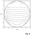
- a progressive lens with a particularly simple surface geometry is selected. It is mirror-symmetrical to a plane perpendicular to the plane of the drawing and essentially consists of only one zone in the middle, running vertically from top to bottom, with a constantly increasing effect.
- This varifocal spectacle lens serves as a comparative varifocal spectacle lens for a varifocal spectacle lens designed according to the invention, which is referred to below as a GRIN varifocal spectacle lens due to its spatially varying refractive index.
- the back of the comparison progressive lens is a spherical surface with a radius of 120 mm and the center of rotation of the eye is behind the geometric center of the lens at a distance of 25.5 mm from the back surface.
- the glass has a center thickness of 2.5mm and a prismatic power of 0 at the geometric center.
- the back surface is not tilted, i.e. both the front surface and the back surface have a normal in the geometric center in the direction of the line of sight, horizontally straight ahead.
- the x and y coordinate axes shown are used to determine points on this surface.
- a spectacle lens with a spherical power is a spectacle lens that combines a paraxial, parallel light beam in a single focal point.
- a spectacle lens with an astigmatic power a spectacle lens that combines a paraxial, parallel light beam in two separate, mutually perpendicular focal lines, and which therefore only has a vertex refractive index in the two principal sections.
- Section 14.2.1 of this standard defines the addition as the difference between the vertex power of the near part and the vertex power of the distance part.
- FIGS. 2a and 2 B show the replica of the comparative progressive lens using a GRIN material.
- Figure 2a shows the distribution of the mean spherical power.
- Figure 1a shows the distribution of the mean spherical power.
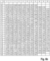
- Figure 2b shows the course of the average surface refractive index of the front surface of the GRIN progressive lens designed according to the invention.
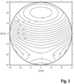
- figure 3 shows the distribution of the refractive index over the GRIN progressive lens according to the invention.
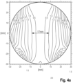
- the Figure 4a and Figure 4b show the effects of using the GRIN material with its special refractive index distribution and the design of the free-form surface for this GRIN progressive lens on the width of the progression channel compared to the standard lens.
- the figures show the distribution of the astigmatic residual errors in the beam path for the Spectacle wearer for a spectacle wearer with a purely spherical prescription.
- the progression channel defined here by the isoastigmatism line 1 dpt, widens from 17 mm to 22 mm, i.e. by about 30 percent.
- FIG. 5a and Figure 5b show cross sections through the residual astigmatism distributions Figure 4a and Figure 4b .
- the conventional relationship between the increase in power and the lateral increase in the astigmatic error induced thereby (similar to the relationship between the mean surface power and surface astigmatism according to Minkwitz's theorem) becomes particularly clear.
- the figure 6 12 compares the contour of the front surface of the GRIN progressive lens according to the first embodiment with the contour of the front surface of the comparative progressive lens by means of an arrowhead representation.
- the Figure 6b shows the arrow heights of the front surface of the GRIN varifocal spectacle lens according to the invention according to the first exemplary embodiment and in comparison thereto Figure 6a the sagitta of the front surface of the comparison progressive power lens.
- the back is again a spherical surface with a radius of 120 mm and the center of rotation of the eye is 4 mm above the geometric center of the comparison progressive lens with a horizontal distance of 25.8 mm to the back surface.
- the comparative progressive lens has a center thickness of 2.6 mm and 2 mm below the geom. Center a prismatic effect 1.0 cm/m base 270° .
- the back surface is tilted by -8° around the horizontal axis.
- the coordinate axes drawn in are used to determine points on this surface.
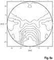
- FIGs 8a and 8b show the replica of the comparative progressive lens using a GRIN material (varifocal lens according to the invention).
- Figure 8a shows the distribution of the mean spherical power.
- Figure 8b shows the course of the average surface refractive index of the front surface of the GRIN progressive lens according to the invention.
- the figure 9 shows the distribution of the refractive index over the lens.
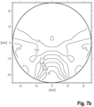
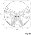
- the Figure 10a and the Figure 10b show the effects of using the GRIN material with its special refractive index distribution and the design of the free-form surface for this GRIN varifocal lens on the width of the progression channel compared to the comparative varifocal lens.
- the figures show the distribution of the astigmatic residual errors in the beam path for the spectacle wearer for a spectacle wearer with purely spherical prescription.
- the progression channel defined here by the isoastigmatism line 1 dpt, widens from 8.5 mm to 12 mm, i.e. by about 41 percent.
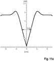
- the Figure 11a and the Figure 11b show cross sections through the residual astigmatism distributions Figure 10a and Figure 10b .
- the conventional relationship between the increase in power and the lateral increase in the astigmatic error induced thereby (similar to the relationship between the mean surface power and surface astigmatism according to Minkwitz's theorem) becomes particularly clear.
- the figure 12 12 compares the contour of the front surface of the GRIN progressive lens according to the second embodiment with the contour of the front surface of the comparative progressive lens by means of an arrowhead representation.
- the Figure 12b shows the arrow heights of the front surface of the GRIN varifocal spectacle lens according to the invention according to the second embodiment and in comparison thereto Figure 12a the sagitta of the front surface of the Comparative varifocal spectacle lens in each case with respect to a coordinate system tilted by -7.02 about a horizontal axis (ie the vertical Y-axis of this system is tilted by -7.02° with respect to the vertical in space).
- the third exemplary embodiment shows two progressive lenses in which the convergence movement of the eye when looking at objects in the intermediate distances and near objects lying straight ahead in front of the eye of the spectacle wearer is taken into account.
- This convergence movement means that the viewing points through the front surface of the spectacle lens do not lie on an exactly vertical straight line when looking at these points, but rather on a vertical line pivoted towards the nose, which is referred to as the main visual line.
- the center of the near zone is also shifted horizontally in the nasal direction.
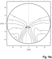
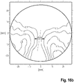
- the examples are calculated in such a way that this main line of sight in the progression area lies in the middle between the lines on the front surface for which the astigmatic residual error is 0.5 dpt (see the Figures 16a and 16b ).
- the back is again a spherical surface with a radius of 120 mm and the center of rotation of the eye is 4 mm above the geometric center of the comparison progressive lens with a horizontal distance of 25.5 mm to the back surface.
- the comparative progressive lens has a center thickness of 2.5 mm and 2 mm below the geom. Center a prismatic power 1.0 cm/m base 270°.
- the back surface is tilted in such a way that when looking horizontally straight ahead, the eye-side ray is perpendicular to the back surface.
- the spectacle wearer When looking horizontally straight ahead (ie for a visual point through the lens of 4 mm above the geometric centre), the spectacle wearer receives an average power of 0 dpt and looking through the point 13 mm below the geometric center and -2.5 mm horizontally in the nasal direction, a mean power of 2.00 D. This means that the lens effect increases by approx. 2.00 dpt over a length of 17 mm.
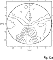
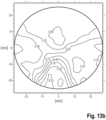
- Figures 14a and 14b show the replica of the comparative progressive lens using a GRIN material (varifocal lens according to the invention).
- Figure 14a shows the distribution of the mean spherical power.
- Figure 14b shows the course of the average surface refractive index of the front surface of the GRIN progressive lens according to the invention.
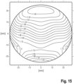
- the figure 15 shows the distribution of the refractive index over the lens.
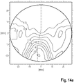
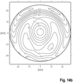
- the Figures 16a and 16b show the effects of using the GRIN material with its special refractive index distribution and the design of the free-form surface for this GRIN varifocal lens on the width of the progression channel compared to the comparative varifocal lens.
- the figures show the distribution of the astigmatic residual errors in the beam path for the spectacle wearer for a spectacle wearer with a purely spherical prescription.
- the progression channel defined here by the isoastigmatism line 1 dpt, widens from 6 mm to 9 mm, i.e. by about 50 percent.
- FIG. 17a and the Figure 17b show cross sections through the residual astigmatism distributions Figure 16a and Figure 16b .
- These figures again illustrate the conventional relationship between power increase and the lateral increase in astigmatic error thereby induced (similar to the relationship of mean sphere to surface astigmatism according to the Minkwitz theorem).
- the figure 18 12 compares the contour of the front surface of the GRIN progressive lens according to the first embodiment with the contour of the front surface of the comparative progressive lens by means of an arrowhead representation.
- the Figure 18b shows the arrow heights of the front surface of the GRIN varifocal spectacle lens according to the invention according to the third embodiment and shows in comparison thereto Figure 18a the heights of the arrows of the front surface of the comparison varifocal spectacle lens in each case with respect to a plane which is perpendicular to the viewing direction and horizontally straight ahead.
- a first step individual user data or application data of the spectacle wearer are recorded. This includes the acquisition of (physiological) data that can be assigned to the spectacle wearer and the acquisition of usage conditions under which the spectacle wearer will wear the varifocal spectacles to be designed.
- the physiological data of the spectacle wearer include, for example, the ametropia and the ability to accommodate, which is determined by means of a refraction measurement and regularly in the form of the prescription values for sphere, cylinder, axis position, prism and base as well as addition to the regulation. Furthermore, for example, the pupil distance and the pupil size are determined under different lighting conditions. The age of the spectacle wearer is taken into account, for example, which has an influence on the expected ability to accommodate and the size of the pupil. The convergence behavior of the eyes results from the pupillary distance for different viewing directions and object distances.
- Conditions of use include the fit of the lenses in front of the eye (usually in relation to the center of rotation of the eye) and the object distances for different viewing directions at which the wearer should see clearly.
- the seat of the spectacle wearer in front of the eye can be determined, for example, by measuring the distance between the corneal vertex and the forward and sideways inclination.
- This data goes into an object distance model for which a ray tracing method can be carried out.
- a draft design for the spectacle lens is defined with a large number of evaluation points.
- the draft design includes target optical properties for the progressive lens at the respective evaluation point.
- the target properties include, for example, the permissible deviation from the prescribed spherical and astigmatic power, taking into account the addition, distributed over the entire progressive lens, as specified by the arrangement of the lens in front of the eye and the distance model on which it is based.
- the front surface can be selected as a spherical surface and the back surface as a progressive surface. Both surfaces could also initially be selected as spherical surfaces.
- the selection of the surface geometry for the first draft generally only determines the convergence (speed and success) of the applied optimization method. For example, assume that the front surface is to retain the spherical shape and the back surface is to be in the form of a progressive addition surface.
- the course of main beams is determined by the large number of evaluation points. If necessary, a local wavefront can be defined for each of the main beams in an area surrounding the respective main beam.
- the above-mentioned optical properties of the spectacle lens are determined at the evaluation points by determining an influence of the spectacle lens on the beam path of the main rays and, if necessary, the local wave fronts in the vicinity of the respective evaluation point.
- the local surface geometry of the rear surface and the local refractive index of the progressive lens in the respective visual beam path are modified by the evaluation points until a termination criterion is met.
- the GRIN progressive lens designed in this way according to the invention can then be manufactured according to this design.
Landscapes
- Physics & Mathematics (AREA)
- Health & Medical Sciences (AREA)
- Ophthalmology & Optometry (AREA)
- General Health & Medical Sciences (AREA)
- General Physics & Mathematics (AREA)
- Optics & Photonics (AREA)
- Mathematical Physics (AREA)
- Eyeglasses (AREA)
- Liquid Crystal (AREA)
Description
Die Erfindung betrifft ein Erzeugnis umfassend ein Gleitsicht-Brillenglas oder eine auf einem Datenträger in Form von computerlesbaren Daten befindliche Darstellung des Gleitsicht-Brillenglases mit Anweisungen für eine Herstellung durch ein additives Verfahren nach dem Oberbegriff des Patentanspruchs 1, ein computerimplementiertes Verfahren zum Entwerfen eines Gleitsicht-Brillenglases zum Zweck der Verwendung des Entwurfs für die Herstellung eines Gleitsicht-Brillenglases nach dem Oberbegriff des Patentanspruchs 7 sowie ein Verfahren zum Herstellen eines Gleitsicht-Brillenglases nach Anspruch 14 sowie ein Computerprogramm nach dem Patentanspruch 12 und ein computerlesbares Medium nach dem Patentanspruch 13.The invention relates to a product comprising a varifocal lens or a representation of the varifocal lens on a data carrier in the form of computer-readable data with instructions for production by an additive method according to the preamble of patent claim 1, a computer-implemented method for designing a varifocal Spectacle lens for the purpose of using the design for the production of a varifocal spectacle lens according to the preamble of patent claim 7 and a method for producing a varifocal spectacle lens according to
Gleitsicht-Brillengläser sind seit Jahrzehnten in der Brillenoptik bekannt und verbreitet. Wie Mehrstärken-Brillengläser (i.A. Zwei- und Dreistärken-Brillengläser) stellen sie dem Alterssichtigen (Presbyopen) eine zusätzliche optische Wirkung im unteren Teil des Glases zum Betrachten naher Objekte, z.B. beim Lesen, zur Verfügung. Diese wird benötigt, da die Augenlinse mit zunehmendem Alter ihre Eigenschaft, auf nahe Objekte fokussieren zu können, mehr und mehr einbüßt. Gleitsichtgläser bieten gegenüber diesen Mehrstärkengläsern den Vorteil, eine stufenlose Zunahme der optischen Wirkung vom Fernteil zum Nahteil bereitzustellen, so dass nicht nur in Ferne und Nähe, sondern auch in allen Zwischenentfernungen ein scharfes Sehen gewährleistet ist.Varifocal lenses have been known and widely used in eyeglass optics for decades. Like multifocal lenses (i.a. two and three-focal lenses), they provide the presbyopia with an additional optical effect in the lower part of the lens for viewing close objects, e.g. when reading. This is needed because the lens of the eye loses more and more of its ability to focus on close objects with increasing age. Compared to these multifocal lenses, progressive lenses offer the advantage of providing a stepless increase in the optical effect from the distant part to the near part, so that sharp vision is guaranteed not only at far and near, but also at all intermediate distances.
Das Fernteil ist nach Abschnitt 14.1.1 der DIN EN ISO 13666:2013-10 das Teil eines Mehrstärken- oder Gleitsicht-Brillenglases, das die dioptrische Wirkung für das Sehen in die Ferne besitzt. Entsprechend ist das Nahteil nach Abschnitt 14.1.3 dieser Norm das Teil eines Mehrstärken- oder Gleitsicht-Brillenglases, das die dioptrische Wirkung für das Sehen in die Nähe besitzt.According to Section 14.1.1 of DIN EN ISO 13666:2013-10, the distance part is the part of a multifocal or progressive lens that has the dioptric power for distance vision. Correspondingly, according to Section 14.1.3 of this standard, the near part is the part of a multifocal or progressive spectacle lens that has the dioptric power for near vision.
Gleitsicht-Brillengläser werden bisher üblicherweise aus einem Material mit einheitlicher konstanter Brechzahl hergestellt. Das bedeutet, dass die dioptrische Wirkung des Brillenglases ausschließlich durch entsprechende Formgebung der beiden an Luft grenzenden Flächen (Vorder- bzw. objektseitige Fläche, sowie Rück- bzw. augenseitige Fläche entsprechend den in den Abschnitten 5.8 und 5.9 der DIN EN ISO 13666:2013-10 bereitgestellten Definitionen) des Brillenglases festgelegt ist. Unter dioptrischer Wirkung ist nach der Definition des Abschnitts 9.3 der DIN EN ISO 13666:2013-10 der Sammelbegriff für die fokussierende und die prismatische Wirkung eines Brillenglases zu verstehen.Up to now, progressive lenses have usually been made from a material with a uniform, constant refractive index. This means that the dioptric effect of the spectacle lens can only be achieved by appropriate shaping of the two surfaces bordering on air (Front or object-side surface, as well as rear or eye-side surface according to the definitions provided in Sections 5.8 and 5.9 of DIN EN ISO 13666:2013-10) of Spectacle lens is fixed. According to the definition in Section 9.3 of DIN EN ISO 13666:2013-10, dioptric power is the collective term for the focusing and prismatic power of a spectacle lens.
Um die stufenlose Zunahme der fokussierenden Wirkung in einem Gleitsicht-Brillenglas aus einem Material mit einheitlicher konstanter Brechzahl zu erzeugen, muss auf mindestens einer der beiden Brillenglasflächen eine entsprechende kontinuierliche Änderung der Flächenkrümmung vorhanden sein, wie dies auch Abschnitt 8.3.5 der Norm DIN EN ISO 13666:2013-10 reflektiert, welcher den Begriff "Gleitsicht-Brillenglas" als "Brillenglas mit mindestens einer Gleitsichtfläche und einer zunehmenden (positiven) Wirkung, wenn der Brillenträger nach unten blickt" definiert. Eine Gleitsichtfläche ist nach Abschnitt 7.7 eine nichtrotationssymmetrische Fläche mit einer kontinuierlichen Änderung der Krümmung über die gesamte Gleitsichtfläche oder einen Teil davon, die im Allgemeinen dazu dient, einen zunehmenden Nahzusatz oder eine Degressionswirkung bereitzustellen.In order to generate the stepless increase in the focusing effect in a progressive lens made of a material with a uniform, constant refractive index, there must be a corresponding continuous change in the surface curvature on at least one of the two lens surfaces, as is also the case in Section 8.3.5 of the DIN EN ISO standard 13666:2013-10, which defines the term "varifocal lens" as "a lens with at least one varifocal surface and an increasing (positive) effect when the wearer looks down". A progressive addition, as defined in Section 7.7, is a non-rotationally symmetrical surface having a continuous change in curvature across all or part of the progressive addition, generally serving to provide an increasing near add or degressive effect.
Die
Die
Die
Weiter führt das Dokument auf Seite 5, Zeile 15ff aus: Wenn zusätzlich auch der Astigmatismus entlang des Hauptmeridians durch die Variation des Brechungsindex verringert wird, so bedeutet dies, dass auch die Einschränkung bei der Gestaltung des Brillenglases, dass der Flächenastigmatismus längs des Hauptmeridians bzw. der Hauptblicklinie klein sein soll, wegfällt, so dass das [...] Brillenglas nicht dem Satz von Minkwitz unterworfen ist, und das Brillenglas unter anderen Gesichtspunkten wesentlich günstiger gestaltet werden kann.The document goes on to say on
Erklärtes Ziel dieses Dokuments ist es, auf einfache Weise polierbare Flächen zu erhalten, indem die Brechungsindexvariation entsprechend kompliziert gestaltet wird. Ausdrücklich wird auf Seite 6, zweitletzter Absatz erklärt: "Dabei ist es im Extremfall sogar möglich, dass beide Flächen des progressiven Brillenglases sphärische Flächen sind. Selbstverständlich ist es aber auch möglich, rotationssymmetrische asphärische Flächen zu verwenden." Andererseits äußert das Dokument keine Einschränkung hinsichtlich der Komplexität der Brechungsindexfunktion, die sich ausweislich des letzten Satzes auf der Seite 6 "beispielsweise mittels Spline-Funktionen beschreiben" lassen kann.The stated goal of this document is to obtain surfaces that can be polished in a simple manner by making the refractive index variation correspondingly complicated. On
Das Dokument offenbart zwei Ausführungsbeispiele. Beim zweiten Ausführungsbeispiel "[sind] sowohl die Vorderfläche als auch die augenseitige Fläche [...] sphärische Flächen" (siehe ebd., S. 11, letzter Satz). Beim ersten Ausführungsbeispiel besitzt die Vorderfläche einen Hauptmeridian in Form eines Kreises (vgl. ebd. S. 12, Z. 6-13) und senkrecht dazu die Gestalt von Kegelschnitten (vgl. ebd., S. 11, Z. 6-14). Die Rückseite ist bei dem ersten Ausführungsbeispiel sphärisch.The document discloses two embodiments. In the second embodiment, "[are] both the front surface and the eye-side surface [...] spherical surfaces" (see ibid., p. 11, last sentence). In the first exemplary embodiment, the front surface has a main meridian in the form of a circle (cf. ibid., p. 12, lines 6-13) and, perpendicular thereto, the shape of conic sections (cf. ibid., p. 11, lines 6-14) . The back is spherical in the first embodiment.
Zum ersten Ausführungsbeispiel weist das Dokument "ausdrücklich [...] daraufhin [...], dass bei der Optimierung die Korrektur von Abbildungsfehlern nicht beachtet worden ist, und dass sich dennoch Gläser mit sehr guten Abbildungseigenschaften in den seitlichen Bereichen ergeben haben. Eine weitere Verbesserung der Abbildungseigenschaften in den Bereichen seitlich des Hauptmeridians erhält man durch weitere Optimierung der Indexfunktion".With regard to the first exemplary embodiment, the document "expressly [...] points out [...] that the correction of imaging errors was not taken into account during the optimization and that glasses with very good imaging properties in the lateral areas were nevertheless obtained. A A further improvement in the imaging properties in the areas to the side of the main meridian can be obtained by further optimizing the index function".
Die
Die
Die
Dem Dokument entnimmt man, das es im Allgemeinen schwierig ist, eine Linse unter Berücksichtigung einer Vielzahl von Kriterien unterschiedlicher Natur zu optimieren, wenn nur die Gleichung einer Oberfläche als variabel betrachtet wird. Diese Ausführungsform ermöglicht es optischen Konstrukteuren, eine größere Anzahl von Kriterien im Optimierungsprozess zu berücksichtigen, und ebnet den Weg für die geometrische Leistungssteigerung des optischen Systems und eine bessere Antwort auf die physiologischen Bedürfnisse von Brillenträgern. Der Nutzen für den Träger wird verbessert, wenn mehrere Oberflächen des optischen Systems gleichzeitig optimiert werden.From the document it can be seen that it is generally difficult to optimize a lens considering a multitude of criteria of different nature if only the equation of a surface is considered to be variable. This embodiment allows optical designers to consider a greater number of criteria in the optimization process and paves the way for optical system geometric performance enhancement and a better response to the physiological needs of eyeglass wearers. The benefit to the wearer is enhanced when multiple surfaces of the optical system are optimized at the same time.
In einer Ausführungsform, in der das zu optimierende optische System mindestens zwei optische Oberflächen umfasst, wird die Modifikation des optischen Arbeitssystems so betrieben, dass zumindest der Index des optischen Arbeitssystems geändert wird. Es ist möglich, eine Linse aus einem inhomogenen Material herzustellen, bei dem im Brechungsindex ein Gradient vorliegt (bekannt als GRIN-Linse). Beispielsweise kann die Verteilung des Index, der optimiert ist, axial oder radial sein und / oder von der Wellenlänge abhängen.In an embodiment in which the optical system to be optimized comprises at least two optical surfaces, the modification of the optical working system is operated in such a way that at least the index of the optical working system is changed. It is possible to make a lens from an inhomogeneous material that has a gradient in the index of refraction (known as a GRIN lens). For example, the distribution of the index that is optimized can be axial or radial and/or dependent on wavelength.
Die
Der
Die Aufgabe der Erfindung wird nunmehr darin gesehen, ein Gleitsicht-Brillenglas bereitzustellen, welches gegenüber den aus dem Stand der Technik bekannten Gleitsicht-Brillengläsern weiter verbesserte optische Eigenschaften für den Brillenträger aufweist und ein Verfahren bereitzustellen, mit welchem ein Gleitsicht-Brillenglas mit weiter verbesserten optischen Abbildungseigenschaften entworfen und hergestellt werden kann.The object of the invention is now seen as providing a varifocal spectacle lens which compared to the varifocal spectacle lenses known from the prior art has further improved optical properties for the spectacle wearer and to provide a method with which a progressive lens can be designed and manufactured with further improved optical imaging properties.
Diese Aufgabe wird durch ein Erzeugnis mit den Merkmalen des Patentanspruchs 1 und ein Verfahren mit den Merkmalen des Patentanspruchs 7 gelöst.This object is achieved by a product having the features of patent claim 1 and a method having the features of patent claim 7 .
Vorteilhafte Ausführungen und Weiterbildungen sind Gegenstand der Unteransprüche.Advantageous designs and developments are the subject of the dependent claims.
Während die
einen räumlich variierenden Brechungsindex auf. Die Vorderfläche oder die Rückfläche oder Vorder- und Rückfläche sind als Gleitsichtfläche ausgebildet. Das Gleitsicht-Brillenglas zeichnet sich nach der Erfindung dadurch aus, dass die als Gleitsichtfläche ausgebildete Vorderfläche als Freiformfläche ausgebildet ist oder dass die als Gleitsichtfläche ausgebildete Rückfläche als Freiformfläche ausgebildet ist oder dass beide als Gleitsichtflächen ausgebildeten Flächen als Freiformflächen ausgebildet sind. Es ist also auch der Fall eingeschlossen, bei dem zwar beide Flächen, nämlich Vorder- und Rückfläche als Gleitsichtflächen ausgebildet sind, aber nur eine der beiden Flächen lediglich als Freiformfläche vorliegt.while the
a spatially varying refractive index. The front surface or the rear surface or front and rear surfaces are designed as progressive surfaces. The progressive lens is characterized according to the invention in that designed as a progressive surface front surface as Freeform surface is formed or that the rear surface formed as a progressive surface is formed as a freeform surface or that both surfaces formed as progressive surfaces are formed as freeform surfaces. This also includes the case in which both surfaces, namely the front and rear surfaces, are in the form of progressive surfaces, but only one of the two surfaces is present as a free-form surface.
Unter dem Ausdruck "auf einem Datenträger befindliche Darstellung eines Gleitsicht-Brillenglases" versteht man im Rahmen der vorliegenden Erfindung z.B. eine in einem Speicher eines Computers gespeicherte Darstellung des Gleitsicht-Brillenglases.In the context of the present invention, the term "representation of a progressive lens located on a data carrier" is understood to mean, for example, a representation of the progressive lens stored in a memory of a computer.
Die Darstellung des Gleitsicht-Brillenglases umfasst insbesondere eine Beschreibung der geometrischen Gestalt und des Mediums des Gleitsicht-Brillenglases. Eine derartige Darstellung kann z.B. eine mathematische Beschreibung der Vorderfläche, der Rückfläche, der Anordnung dieser Flächen zueinander (einschließlich der Dicke) und der Randbegrenzung des Gleitsicht-Brillenglases sowie der Brechzahlverteilung des Mediums, aus dem das Gleitsicht-Brillenglas bestehen soll, umfassen. Die Darstellung kann in kodierter oder gar in verschlüsselter Form vorliegen. Unter Medium ist hier das Material/die Materialien bzw. der Stoff gemeint, aus dem das Gleitsicht-Brillenglas gefertigt ist. Das Gleitsicht-Brillenglas kann auch aus mehreren Schichten bestehen, z.B. auch aus einem Dünnstglas mit einer Dicke zwischen 10 µm und 500 µm und darauf aufgebrachtem Kunststoff.The representation of the varifocal lens includes in particular a description of the geometric shape and the medium of the varifocal lens. Such a representation can include, for example, a mathematical description of the front surface, the back surface, the arrangement of these surfaces in relation to one another (including the thickness) and the edge limitation of the varifocal lens and the refractive index distribution of the medium from which the varifocal lens is to be made. The representation can be in coded or even in encrypted form. The medium here means the material/materials or substance from which the progressive lens is made. The progressive lens can also consist of several layers, e.g. also of an extremely thin glass with a thickness between 10 µm and 500 µm and plastic applied to it.
Die Vorderfläche oder objektseitige Fläche eines Brillenglases ist nach Abschnitt 5.8 der DIN EN ISO 13666:2013-10 die Fläche eines Brillenglases, die bestimmungsgemäß in der Brille vom Auge abgewandt liegt. Demgemäß ist nach Abschnitt 5.9 dieser Norm die Rückfläche die augenseitige Fläche, also die Fläche eines Brillenglases, die bestimmungsgemäß in der Brille dem Auge zugewandt liegt.According to Section 5.8 of DIN EN ISO 13666:2013-10, the front surface or object-side surface of a spectacle lens is the surface of a spectacle lens that is intended to be in the spectacles and faces away from the eye. According to Section 5.9 of this standard, the back surface is the surface on the eye side, i.e. the surface of a spectacle lens that is intended to face the eye in the spectacles.
Eine Gleitsichtfläche ist nach Abschnitt 7.7 der DIN EN ISO 13666:2013-10 eine nichtrotationssymmetrische Fläche mit einer kontinuierlichen Änderung der Krümmung über die gesamte Fläche oder einen Teil davon, die im Allgemeinen dazu dient, einen zunehmenden Nahzusatz oder eine Degressionswirkung bereitzustellen. Eine kontinuierliche Änderung schließt sprunghafte Änderungen aus. Im Allgemeinen bedeutet insbesondere im Rahmen der Erfindung, dass der Nahzusatz oder die Degressionswirkung bereitgestellt werden kann aber nicht muss. Insbesondere kann im Rahmen der vorliegenden Erfindung der räumlich variierende Brechungsindex zumindest teilweise diese Aufgabe übernehmen. Jede Freiformfläche ist nach dieser Definition eine Gleitsichtfläche aber nicht umgekehrt.According to Section 7.7 of DIN EN ISO 13666:2013-10, a progressive surface is a non-rotationally symmetrical surface with a continuous change in curvature over the entire surface or part of it, which generally serves to provide an increasing near addition or a degression effect. A continuous change excludes sudden changes. In general, particularly within the scope of the invention, means that the near addition or the degression effect can be provided but does not have to be. In particular, within the scope of the present invention, the spatially varying Refractive index at least partially take over this task. According to this definition, every free-form surface is a progressive surface, but not vice versa.
Unter einer Freiformfläche versteht man im weiteren Sinn eine komplexe Fläche, die sich insbesondere mittels ausschließlich (insbesondere stückweise) polynomialer Funktionen (insbesondere polynomiale Splines, wie z.B. bikubische Splines, höhergradige Splines vierten Grades oder höher, Zernike-Polynome, Forbes-Flächen, Tschebyschew-Polynome, Fourierreihen, polynomiale Non-uniform rational B-Splines (NURBS)) darstellen lässt. Hiervon zu unterscheiden sind einfache Flächen, wie z.B. sphärische Flächen, asphärische Flächen, zylindrische Flächen, torische Flächen oder auch die in der
Die Erfindung ist dadurch gekennzeichnet, dass das erfindungsgemäße Gleitsicht-Brillenglas so gestaltet ist, dass es für den Gleitsicht-Brillenträger die nachfolgend beschriebenen gegenüber einem Vergleichs-Gleitsicht-Brillenglas, welches keine räumliche Brechungsindexvariation aber eine identische Verteilung des sphärischen Äquivalents aufweist, vorteilhafteren optischen Eigenschaften besitzt.The invention is characterized in that the varifocal spectacle lens according to the invention is designed in such a way that the varifocal spectacle wearer has the optical properties described below that are more advantageous than a comparative varifocal spectacle lens, which has no spatial refractive index variation but an identical distribution of the spherical equivalent owns.
Erläuternd wird ausgeführt, dass ein Brillenglas für eine vorbestimmte Anordnung vor einem Auge eines Brillenträgers und für eine oder mehrere vorbestimmte Objektentfernungen, unter denen der Brillenträger ein Objekt scharf wahrnehmen soll, konzipiert ist. In einer davon abweichenden Anordnung vor dem Auge des Brillenträgers und für andere Objektentfernungen ist das Brillenglas wertlos oder die optische Qualität ist für den Brillenträger stark eingeschränkt. Dies gilt umso mehr für Gleitsicht-Brillengläser. Demnach ist ein Gleitsicht-Brillenglas lediglich über die Kenntnis der vorbestimmten Anordnung vor dem Auge des Brillenträgers charakterisiert. Anders ausgedrückt ist die Kenntnis der Anordnung des Brillenglases in Ort und Ausrichtung im Raum in Bezug auf das Auge notwendig aber auch hinreichend, um dieses in eineindeutiger Weise in dessen optischer Wirkung für den Brillenträger zu charakterisieren. Darüber hinaus ist ein Optiker auch nur dann in der Lage, das Brillenglas lagerichtig in eine Brillenfassung einzusetzen, wenn er die Anordnung des Brillenglases in Ort und Ausrichtung in Bezug auf das Auge des Brillenträgers kennt. Eine Darstellung der vorbestimmten Anordnung des Gleitsicht-Brillenglases vor einem Auge eines Gleitsicht-Brillenträgers, für den das Gleitsicht-Brillenglas bestimmt ist, ist damit untrennbarer Bestandteil des Produkts (Erzeugnis) oder der Handelsware "Gleitsicht-Brillenglas".By way of explanation, it is stated that a spectacle lens is designed for a predetermined arrangement in front of an eye of a spectacle wearer and for one or more predetermined object distances at which the spectacle wearer should perceive an object sharply. In a different arrangement in front of the eye of the spectacle wearer and for other object distances, the spectacle lens is worthless or the optical quality is severely restricted for the spectacle wearer. This applies all the more to varifocal lenses. Accordingly, a varifocal spectacle lens is only characterized by the knowledge of the predetermined arrangement in front of the eye of the spectacle wearer. In other words, knowledge of the arrangement of the spectacle lens in terms of location and orientation in space in relation to the eye is necessary but also sufficient in order to characterize the optical effect for the spectacle wearer in a unique way. In addition, an optician is only able to insert the spectacle lens in the correct position in a spectacle frame if he knows the arrangement of the spectacle lens in terms of location and orientation in relation to the eye of the spectacle wearer. A representation of the predetermined arrangement of the varifocal spectacle lens in front of an eye of a varifocal spectacle wearer for whom the varifocal lens is therefore an inseparable part of the product (article) or commodity "varifocal lens".
Der Hersteller bringt zum Zweck der Gewährleistung einer lage- und orientierungsrichtigen Anordnung im Gleitsicht-Brillenglas durch den Optiker permanent vorhandene Markierungen an. Der DIN EN ISO 13666:2013-10 entnimmt man unter 14.1.24, dass diese als Markierung zur Ausrichtung oder Permanentmarkierung bezeichnet wird und vom Hersteller angebracht wurde, um die horizontale Orientierung des Brillenglases [...] oder die Rekonstruktion weiterer Bezugspunkte zu ermöglichen. Nach Abschnitt 6.1 der DIN EN ISO 14889:2009 muss der Hersteller rohkantiger fertiger Brillengläser durch Angaben auf der Einzelverpackung oder in einem Begleitdokument eine Identifizierung ermöglichen. Insbesondere hat er Korrekturwerte für Gebrauchssituationen, die Nahzusatzwirkung, die Typbezeichnung oder den Handelsnamen und die notwendige Information, um den Nahzusatz zu messen. Aus der Typbezeichnung oder dem Handelsnamen ergibt sich das von dem Hersteller dem Gleitsicht-Brillenglas zugrunde gelegte Objektabstandsmodell. Unter Hersteller ist nach 3.1 dieser Norm eine natürliche oder juristische Person, die das rohkantige fertige Brillenglas auf den Markt bringt, zu verstehen.For the purpose of ensuring that the varifocal lens is correctly positioned and orientated, the manufacturer applies permanent markings to the optician. DIN EN ISO 13666:2013-10 under 14.1.24 states that this is referred to as a marking for alignment or permanent marking and was applied by the manufacturer to enable the horizontal orientation of the spectacle lens or the reconstruction of further reference points . According to Section 6.1 of DIN EN ISO 14889:2009, the manufacturer of raw-edged finished spectacle lenses must enable identification by providing information on the individual packaging or in an accompanying document. In particular, he has correction values for situations of use, the near-add effect, the type designation or the trade name and the necessary information to measure the near-add add. The object distance model on which the manufacturer of the progressive lens is based results from the type designation or the trade name. According to 3.1 of this standard, the manufacturer is a natural or legal person who puts the raw-edged, finished spectacle lens on the market.
Das erfindungsgemäße Erzeugnis umfasst ferner eine auf einem Datenträger befindliche Darstellung einer vorbestimmten Anordnung des Gleitsicht-Brillenglases vor einem Auge eines Gleitsicht-Brillenträgers, für den das Gleitsicht-Brillenglas bestimmt ist. Wie bereits ausgeführt weist das erfindungsgemäß ausgebildete Gleitsicht-Brillenglas (nicht nur) bei dieser Variante eine Verteilung eines sphärisches Äquivalents für die vorbestimmte Anordnung des Gleitsicht-Brillenglases vor dem Auge des Gleitsicht-Brillenträgers, für den das Gleitsicht-Brillenglas bestimmt ist, auf. Ferner weist das erfindungsgemäß ausgebildete Gleitsicht-Brillenglas einen Progressionskanal mit einer Breite auf. Das erfindungsgemäß nach dieser Variante konzipierte Gleitsicht-Brillenglas besitzt einen Brechungsindex, der räumlich derart variiert, dass die Breite des Progressionskanals des Gleitsicht-Brillenglases wenigstens in einem Schnitt oder über die gesamte Länge des Progressionskanals größer ist, als die Breite des Progressionskanals eines Vergleichs-Gleitsicht-Brillenglases mit gleicher Verteilung des sphärischen Äquivalents bei gleicher Anordnung des Vergleichs-Gleitsicht-Brillenglases vor dem Auge des GleitsichtBrillenträgers aber räumlich nicht variierendem Brechungsindex.The product according to the invention also comprises a representation on a data carrier of a predetermined arrangement of the varifocal spectacle lens in front of an eye of a varifocal spectacle wearer for whom the varifocal spectacle lens is intended. As already stated, the progressive lens designed according to the invention (not only) in this variant has a distribution of a spherical equivalent for the predetermined arrangement of the progressive lens in front of the eye of the progressive lens wearer for whom the progressive lens is intended. Furthermore, the progressive lens designed according to the invention has a progression channel with a width. The progressive lens designed according to this variant according to the invention has a refractive index that varies spatially in such a way that the width of the progression channel of the progressive lens is greater, at least in one section or over the entire length of the progression channel, than the width of the progression channel of a comparative progressive lens spectacle lens with the same distribution of the spherical equivalent with the same arrangement of the comparative progressive lens in front of the eye of the progressive lens wearer, but with a refractive index that does not vary spatially.
Der Begriff "sphärisches Äquivalent" ist hierbei definiert als das arithmetische Mittel der fokussierenden Wirkung, wie dies beispielsweise aus 
Die fokussierende Wirkung ist nach Abschnitt 9.2 der DIN EN ISO 13666:2013-10 der Sammelbegriff für die sphärische und astigmatische Wirkung eines Brillenglases. Die sphärische Wirkung ist in der Gleichung durch "Sphäre" abgekürzt, die astigmatische Wirkung ist repräsentiert durch "Zylinder". Für den Begriff sphärisches Äquivalent wird auch der Begriff mittlere sphärische Wirkung verwendet.According to Section 9.2 of DIN EN ISO 13666:2013-10, the focusing effect is the collective term for the spherical and astigmatic effect of a spectacle lens. The spherical power is abbreviated in the equation by "Sphere", the astigmatic power is represented by "Cylinder". The term mean spherical power is also used for the term spherical equivalent.
Der Progressionskanal ist -wie oben bereits ausgeführt wurde- nach der DIN EN ISO 13666:2013-10 Absatz 14.1.25 der Bereich eines Gleitsicht-Brillenglases, der scharfes Sehen für Entfernungen ermöglicht, die zwischen der Ferne und der Nähe liegen. In der Mitte des Progressionskanals verläuft die Hauptblicklinie, welche die Gesamtheit aller Durchblickpunkte durch die Gleitsichtfläche bei der Blickbewegung des Auges auf Objektpunkte geradeaus vor dem Brillenträger von der Ferne zur Nähe darstellt. Die Hauptblicklinie wird regelmäßig auf der Vorderfläche angenommen. Anders ausgedrückt wird als Hauptblicklinie diejenige Linie auf der Vorderfläche eines Brillenglases bezeichnet, die die Hauptdurchblickpunkte durch das Gleitsichtglas für das Sehen in die Ferne und in die Nähe miteinander verbindet und auf der die Durchstoßpunkte der Sehstrahlen für Zwischenentfernungen in Richtung "geradeaus" liegen (Anmerkung: die Verwendung der Rückfläche als Bezugsfläche, auf der die Hauptblicklinie liegt ist eher unüblich). Die Hauptblicklinie ist regelmäßig eine im Fern- und im Nahteil angenähert senkrecht und im Progressionskanal, also dem Teil eines Gleitsicht-Brillenglases, das die dioptrische Wirkung für das Sehen in Entfernungen besitzt, die zwischen Ferne und Nähe liegen, gewunden verlaufende Linie. Die Länge des Progressionskanals kann sich z.B. durch die Lage der Fern- und Nah-Konstruktionsbezugspunkte oder die Lage der Fern- und Nah-Bezugspunkte ergeben. Der Fern-Konstruktionsbezugspunkt ist nach 5.13 der DIN EN ISO 13666:2013-10 der Punkt auf der Vorderfläche eines fertigen Brillenglases oder der fertig bearbeiteten Fläche eines Brillenglasblanks, in dem nach Angabe des Herstellers die Konstruktions-Sollwerte für das Fernteil vorliegen. Entsprechend ist nach 5.14 dieser Norm der Nah-Konstruktionsbezugspunkt der Punkt auf der Vorderfläche eines fertigen Brillenglases oder der fertig bearbeiteten Fläche eines Brillenglasblanks, in dem nach Angabe des Herstellers die Konstruktions-Sollwerte für das Nahteil vorliegen. Nach 5.15 ist der Fern-Bezugspunkt bzw. Hauptbezugspunkt der Punkt auf der Vorderfläche eines Brillenglases, in dem die dioptrische Wirkung für das Fernteil erreicht werden muss und nach 5.17 ist der Nah-Durchblickpunkt die angenommene Lage des Durchblickpunktes auf einem Brillenglas für das Sehen in die Nähe unter bestimmten Bedingungen.According to DIN EN ISO 13666:2013-10 paragraph 14.1.25, the progression channel is - as already explained above - the area of a varifocal lens that enables sharp vision for distances that lie between far and near. The main line of sight runs in the middle of the progression channel, which represents the entirety of all visual points through the progressive surface during the gaze movement of the eye to object points straight in front of the spectacle wearer from distance to near. The main line of sight is regularly assumed to be on the front surface. In other words, the main visual line is that line on the front surface of a spectacle lens that connects the main visual points through the progressive lens for distance and near vision and on which the intersection points of the visual rays for intermediate distances in the "straight ahead" direction lie (note: the use of the back surface as a reference surface on which the main line of sight lies is rather unusual). The main line of sight is regularly an approximately vertical one in the far and near parts and runs tortuously in the progression channel, i.e. the part of a progressive lens that has the dioptric power for seeing at distances that lie between far and near. The length of the progression channel can result, for example, from the position of the far and near construction reference points or the position of the far and near reference points. According to 5.13 of DIN EN ISO 13666:2013-10, the distance design reference point is the point on the front surface of a finished spectacle lens or the finished surface of a spectacle lens blank which, according to the manufacturer, contains the target design values for the distance part. Accordingly, according to 5.14 of this standard, the near design reference point is the point on the front surface of a finished lens or the finished surface of a lens blank in which, according to the manufacturer, the design values for the Near part available. According to 5.15, the distance reference point or main reference point is the point on the front surface of a spectacle lens in which the dioptric power for the distance part must be achieved and according to 5.17 the near visual point is the assumed position of the visual point on a spectacle lens for seeing into the proximity under certain conditions.
Grundsätzlich ist es möglich, anhand der vorstehenden Angabe die Eigenschaften des Gleitsicht-Brillenglases im Verhältnis zu einem Vergleichs-Gleitsicht-Brillenglas in eineindeutiger Weise festzulegen und festzustellen. Ein einfaches Kriterium ergibt sich, wenn man annimmt, dass der wenigstens eine Schnitt eine Variante aus der Gruppe
- horizontaler Schnitt bei halber Addition (insbesondere auf der Hauptblicklinie) und horizontaler Schnitt bei 25 % der Addition (insbesondere auf der Hauptblicklinie)
- horizontaler Schnitt bei halber Addition (insbesondere auf der Hauptblicklinie) und horizontaler Schnitt bei 75 % der Addition (insbesondere auf der Hauptblicklinie)
- horizontaler Schnitt bei halber Addition (insbesondere auf der Hauptblicklinie) und horizontaler Schnitt bei 25 % der Addition (insbesondere auf der Hauptblicklinie) und horizontaler Schnitt bei 75 % der Addition (insbesondere auf der Hauptblicklinie) ist.
- horizontal cut at half addition (especially on the principal line of sight) and horizontal cut at 25% of addition (especially on the principal line of sight)
- horizontal cut at half addition (particularly on the principal line of sight) and horizontal cut at 75% of addition (particularly on the principal line of sight)
- horizontal cut at half addition (particularly on the principal line of sight) and horizontal cut at 25% of addition (particularly on the principal line of sight) and horizontal cut at 75% of addition (particularly on the principal line of sight).
Die DIN EN ISO 13666:2013-10 definiert in Abschnitt 14.2.1 den Nahzusatz bzw. die Addition als Differenz zwischen dem Scheitelbrechwert des Nahteiles und dem Scheitelbrechwert des Fernteiles gemessen mit festgelegten Verfahren. Diese Norm gibt an, dass entsprechende Messverfahren in der für Brillengläser maßgebenden Norm enthalten seien. Als maßgebende Norm wird in der DIN EN ISO 13666:2013-10 auf die DIN EN ISO 8598-1:2012, "Optik und optische Instrumente - Scheitelbrechwert-Messgeräte - Teil 1: Instrumente für den allgemeinen Gebrauch" verwiesen. Der Scheitelbrechwert ist in der DIN EN ISO 13666:2013-10, Abschnitt 9.7 wie folgt definiert. Es wird unterschieden zwischen bildseitigem Scheitelbrechwert, welcher definiert ist als Kehrwert der paraxialen Schnittweite des bildseitigen Brennpunktes, gemessen in Metern und objektseitigem Scheitelbrechwert, welcher definiert ist als Kehrwert der paraxialen Schnittweite des objektseitigen Brennpunktes, gemessen in Metern. Es wird angemerkt, dass nach Übereinkunft in der Augenoptik der bildseitige Scheitelbrechwert der "Scheitelbrechwert" eines Brillenglases verwendet wird, für bestimmte Zwecke aber auch der objektseitige Scheitelbrechwert benötigt wird, z. B. zur Messung der Addition bei einigen Mehrstärken- und Gleitsicht-Brillengläsern.In Section 14.2.1, DIN EN ISO 13666:2013-10 defines near addition or addition as the difference between the vertex power of the near part and the vertex power of the distance part, measured using specified methods. This standard states that the corresponding measuring methods are contained in the standard applicable to spectacle lenses. DIN EN ISO 13666:2013-10 refers to DIN EN ISO 8598-1:2012, "Optics and optical instruments - Lens measuring devices - Part 1: Instruments for general use" as the authoritative standard. The vertex power is defined as follows in DIN EN ISO 13666:2013-10, Section 9.7. A distinction is made between image-side vertex power, which is defined as the reciprocal of the paraxial back focus of the image-side focal point, measured in meters, and object-side vertex power, which is defined as the reciprocal of the paraxial back focus of the object-side focal point, measured in meters. It is noted that by convention in ophthalmic optics the image-side vertex power of a spectacle lens is used, but for certain purposes the object-side vertex power is also required, e.g. B. to measure the addition of some multifocal and progressive lenses.
Die erfindungsgemäße Variante die Eigenschaften des Gleitsicht-Brillenglases über einen Vergleich mit den Eigenschaften eines Vergleichs-Gleitsicht-Brillenglases mit in eineindeutiger Weise vorbestimmbaren Eigenschaften, nämlich derselben Verteilung des sphärischen Äquivalents über das Glas unter der derselben Position des Brillenglases vor dem Auge des selben Gleitsicht-Brillenträgers unter Zugrundelegung des selben Objektabstandsmodells, zu definieren, besteht darin, wenn das Erzeugnis ferner
- (i) eine auf einem Datenträger befindliche Darstellung einer Restastigmatismusverteilung für die vorbestimmte Anordnung des Gleitsicht-Brillenglases vor dem Auge des Gleitsicht-Brillenträgers, für den das Gleitsicht-Brillenglas bestimmt ist, und/oder
- (ii) eine auf einem Datenträger befindliche Darstellung einer für eine Vollkorrektion geforderte astigmatische Wirkungsverteilung für die vorbestimmte Anordnung des Gleitsicht-Brillenglases vor dem Auge des Gleitsicht-Brillenträgers, für den das Gleitsicht-Brillenglas bestimmt ist, und/oder
- (iii) eine auf einem Datenträger befindliche Darstellung einer Verordnung und eines Objektabstandsmodells für die vorbestimmte Anordnung des Gleitsicht-Brillenglases vor dem Auge eines Gleitsicht-Brillenträgers, für den das Gleitsicht-Brillenglas bestimmt ist, und/oder
- (iv) eine auf einem Datenträger befindliche Darstellung einer Verteilung des sphärischen Äquivalents für die vorbestimmte Anordnung des Gleitsicht-Brillenglases vor dem Auge des Gleitsichtbrillenträgers, für den das Gleitsichtbrillenglas bestimmt ist, aufweist.
- (i) a representation on a data carrier of a residual astigmatism distribution for the predetermined arrangement of the progressive lens in front of the eye of the progressive lens wearer for whom the progressive lens is intended, and/or
- (ii) a representation on a data carrier of an astigmatic power distribution required for a full correction for the predetermined arrangement of the varifocal spectacle lens in front of the eye of the varifocal spectacle wearer for whom the varifocal spectacle lens is intended, and/or
- (iii) a representation on a data carrier of a prescription and an object distance model for the predetermined arrangement of the progressive lens in front of the eye of a progressive lens wearer for whom the progressive lens is intended, and/or
- (iv) a representation on a data carrier of a distribution of the spherical equivalent for the predetermined arrangement of the progressive lens in front of the eye of the progressive lens wearer for whom the progressive lens is intended.
Bei dem erfindungsgemäßen Gleitsicht-Brillenglases, welches ein Fernteil und ein Nahteil aufweist, wird die Breite des Progressionskanals durch die Abmessung quer zu einer zwischen Fernteil und Nahteil verlaufenden Längsrichtung des Progressionskanals definiert, innerhalb der der Wert des Betrags des Restastigmatismus unterhalb eines vorbestimmten Grenzwerts liegt, der innerhalb eines Bereichs aus der nachfolgend angegebenen Gruppe ausgewählt ist:
- (a) der Grenzwert liegt
im Bereich zwischen 0,25 dpt und 1,0 dpt - (b) der Grenzwert liegt
im Bereich zwischen 0,25 dpt und 0,75 dpt - (c) der Grenzwert liegt
im Bereich zwischen 0,25 dpt und 0,6 dpt - (d) der Grenzwert liegt
im Bereich zwischen 0,25 dpt und 0,5 dpt - (e) der Grenzwert beträgt 0,5 dpt.
- (a) the threshold is in the range between 0.25 D and 1.0 D
- (b) the threshold is in the range between 0.25 D and 0.75 D
- (c) the threshold is in the range between 0.25 D and 0.6 D
- (d) the threshold is in the range between 0.25 D and 0.5 D
- (e) the threshold is 0.5 dpt.
Unter Restastigmatismus versteht man den Astigmatismus (nach Betrag und Achsrichtung), um den der Astigmatismus bzw. die astigmatische Wirkung des Gleitsicht-Brillenglases an einem jeweiligen Ort auf einer Gleitsicht-Brillenglasfläche für ein das Gleitsicht-Brillenglas an diesem Ort durchdringenden Strahlenbündels für den Gleitsicht-Brillenträger, für den das GleitsichtBrillenglas bestimmt ist, wenn der Gleitsicht-Brillenträger das Gleitsicht-Brillenglas bestimmungsgemäß trägt (so dass es in vorbestimmter Weise vor dem Auge des GleitsichtBrillenträgers angeordnet ist), von der für eine Vollkorrektion geforderten astigmatischen Wirkung abweicht. Der Begriff "Verteilung" stellt klar, dass dieser Restastigmatismus lokal über das Brillenglas unterschiedlich sein kann und im Regelfall auch sein wird.Residual astigmatism means the astigmatism (according to amount and axial direction) by which the astigmatism or the astigmatic effect of the varifocal lens at a particular location on a varifocal lens surface for a beam of rays penetrating the varifocal lens at this location for the varifocal lens Spectacles wearer for whom the varifocal lens is intended deviates from the astigmatic power required for full correction if the varifocal wearer wears the varifocal lens as intended (so that it is arranged in a predetermined manner in front of the eye of the varifocal wearer). The term "distribution" makes it clear that this residual astigmatism can vary locally across the spectacle lens and will generally vary.
Anders formuliert versteht man unter Restastigmatismus die Abweichung der astigmatischen Wirkung (astigmatische Ist-Wirkung) des Gleitsicht-Brillenglases von der "verordneten" astigmatischen Wirkung bezüglich Betrag und Achslage. Anders ausgedrückt ist der Restastigmatismus die blickrichtungsabhängige Differenz zwischen der astigmatischen Ist-Wirkung und der astigmatischen Soll-Wirkung für den Träger des Gleitsicht-Brillenglases in Gebrauchsstellung. Berücksichtigt wird bei der Gebrauchsstellung die Position und Orientierung des Brillenglases zum Auge bei bestimmungsgemäßem Gebrauch. Die Blickrichtungsabhängigkeit der astigmatischen Wirkung kann insbesondere aus der Blickrichtungsabhängigkeit der Objektentfernung und der Blickrichtungsabhängigkeit der astigmatischen Wirkung des Auges resultieren. Der Ausdruck "verordnete Wirkung" ist also im weitesten Sinn als Soll-Wirkung zu verstehen, die das Brillenglas aufgrund seiner zugrunde gelegten Position und Orientierung in Bezug auf das Auge für die jeweilige Blickrichtung und die Entfernung, in welcher der Brillenträger das Objekt für diese Blickrichtung scharf sehen soll, haben soll.In other words, residual astigmatism is the deviation of the astigmatic power (actual astigmatic power) of the progressive lens from the "prescribed" astigmatic power in terms of amount and axis position. In other words, the residual astigmatism is the direction-of-view-dependent difference between the actual astigmatic power and the target astigmatic power for the wearer of the progressive lens in the position of use. The usage position takes into account the position and orientation of the spectacle lens in relation to the eye when used as intended. The dependence of the astigmatic power on the viewing direction can result in particular from the dependence of the object distance on the viewing direction and the dependence of the astigmatic power of the eye on the viewing direction. The expression "prescribed effect" is therefore to be understood in the broadest sense as the target effect that the spectacle lens, based on its underlying position and orientation in relation to the eye for the respective viewing direction and the distance at which the spectacle wearer sees the object for this viewing direction should see sharply, should have.
Für die konkrete Berechnung der Restastigmatismusverteilung (oder anderer Fehlerverteilungen, wie z.B. der sphärischen Fehlerverteilung oder sonstigen z.B. in der
Die Restastigmatismusverteilung kann bereits als errechnete mathematische Beschreibung vorliegen (wie im Fall (i)) oder sie lässt sich aus der Verordnung (häufig wird auch der Begriff Rezept verwendet) und einem Objektabstandsmodell (wie im Fall (iii)) oder einer bereits berechneten astigmatischen Wirkungsverteilung für Vollkorrektion (wie im Fall (ii)) ermitteln.The residual astigmatism distribution can already exist as a calculated mathematical description (as in case (i)) or it can be derived from the prescription (the term prescription is also often used) and an object distance model (as in case (iii)) or an already calculated astigmatic power distribution for full correction (as in case (ii)).
Die Verordnung kann neben den herkömmlichen Refraktionswerten auch weitere dem Brillenträger inhärente physiologische Parameter (also allgemein solche Parameter, die dem Brillenträger eigen sind) sowie die Gebrauchsbedingungen (also allgemein solche Parameter, die der Umgebung des Brillenträgers zuordenbar sind), unter denen das verordnete GleitsichtBrillenglas getragen werden soll, umfassen. Zu den inhärenten physiologischen Parametern gehören u.a. die Fehlsichtigkeit, die Akkommodationsfähigkeit und die (ggf. auch monokulare) Pupillendistanz des Brillenträgers. Zu den Gebrauchsbedingungen gehören Informationen zum Sitz der Gläser vor dem Auge und auch Daten, die das Objektabstandsmodell charakterisieren, wie z.B. ob es sich um eine Bildschirmarbeitsplatzbrille handeln soll, welches für die Fernblickrichtung ein Objekt, nämlich den Bildschirm, in einer von unendlich abweichenden Entfernung zugrunde legt. Für den Fall dass, die individuell gemessene oder bestimmte Verordnung bestimmte Gebrauchsbedingungen nicht enthält, werden gewisse Standardwerte angenommen (z.B. Standardvorneigung 9°)In addition to the conventional refraction values, the prescription can also include other physiological parameters inherent in the spectacle wearer (i.e. generally parameters that are inherent to the spectacle wearer) and the conditions of use (i.e. generally parameters that can be assigned to the environment of the spectacle wearer) under which the prescribed varifocal lenses are worn should include. The inherent physiological parameters include the ametropia, the ability to accommodate and the (possibly also monocular) interpupillary distance of the spectacle wearer. The conditions of use include information on the position of the glasses in front of the eye and also data that characterize the object distance model, such as whether it should be a question of VDU workstation glasses, which are based on an object, namely the screen, at a distance deviating from infinity for the long-distance viewing direction lays. In the event that the individually measured or specific prescription does not contain certain conditions of use, certain standard values are assumed (e.g. standard forward inclination 9°)
Unter Objektabstandsmodell versteht man eine Annahme für Entfernungen im Raum unter denen der Brillenträger Objekte scharf sehen soll. Bei dem Objektabstandsmodell wird die Objektlage im Allgemeinen auf den Augendrehpunkt bezogen, wie dies oben bereits ausgeführt wurde.The object distance model is an assumption for distances in space at which the wearer of the glasses should see objects sharply. In the object distance model, the object position is generally related to the center of rotation of the eye, as has already been explained above.
Die Modellrechnung kann berücksichtigen, dass sich die Wirkung und Achslage des Auges bei unterschiedlichen Objektentfernungen und Blickrichtungen ändert. Die Modellrechnung kann insbesondere die sogenannte Listing'sche Regel berücksichtigen. Die Modellrechnung kann z.B. auch die Änderung der astigmatischen Wirkung des Auges für die Nähe und die Ferne berücksichtigen, beispielsweise in der Art wie dies in der
Vollkorrektion bezeichnet im Rahmen der vorliegenden Erfindung eine durch das bestimmungsgemäße Tragen der Gleitsicht-Brille bewirkte Korrektion, die es dem Gleitsicht-Brillenträger unter Berücksichtigung der durch die Verordnung repräsentierten Seheigenschaften seines Auges erlaubt, in den Entfernungen angeordnete Objekte, die dem Objektabstandsmodell zugrunde gelegt sind, scharf zu sehen.In the context of the present invention, full correction refers to a correction brought about by wearing the varifocal glasses as intended, which the varifocal glasses wearer allows, taking into account the visual properties represented by the prescription his eye allows objects arranged in the distances on which the object distance model is based to be seen sharply.
Es sei der Vollständigkeit halber darauf hingewiesen, dass der Datenträger, auf dem sich die vorbestimmte Darstellung befindet z.B. anstelle eines Speichers eines Computers auch ein Blatt Papier sein kann. Dies betrifft insbesondere den o.a. Fall (iii), in dem die Verordnung auch auf einem Blatt Papier notiert sein kann.For the sake of completeness, it should be pointed out that the data medium on which the predetermined representation is located can also be a sheet of paper, for example, instead of a computer memory. This applies in particular to case (iii) above, in which the regulation can also be written down on a piece of paper.
Die eingangs beschriebene Aufgabe wird durch das vorgeschlagene Gleitsicht-Brillenglas vollumfänglich gelöst.The task described at the outset is achieved in its entirety by the proposed progressive lens.
In weiterer Ausgestaltung der Erfindung ist vorgesehen, dass die Freiformfläche eine Freiformfläche im engeren Sinn entsprechend dem Abschnitt 2.1.2 der DIN SPEC 58194 vom Dezember 2015 ist, nämlich eine in Freiformtechnologie gefertigte Brillenglasfläche, die im Rahmen der Grenzen der Differentialgeometrie mathematisch beschrieben wird und weder punkt- noch achsensymmetrisch ist.In a further embodiment of the invention, it is provided that the free-form surface is a free-form surface in the narrower sense corresponding to Section 2.1.2 of DIN SPEC 58194 of December 2015, namely a spectacle lens surface manufactured using free-form technology, which is described mathematically within the limits of differential geometry and neither is point symmetric nor axisymmetric.
Weiter insbesondere kann die Freiformfläche keine Punktsymmetrie, keine Achsensymmetrie, keine Rotationssymmetrie und keine Symmetrie bzgl. einer Symmetrieebene aufweisen. Obwohl es günstig ist, jede Beschränkung hinsichtlich der Flächengeometrie aufzuheben, ist es in Anbetracht derzeit üblicher Anforderungen an die optischen Eigenschaften von Gleitsicht-Brillengläsern hinreichend, nur Freiformflächen mit einem hohen Grad an Komplexität als Gleitsichtflächen zuzulassen. Lässt man darüber hinaus dasselbe Maß an Komplexität für die Brechungsindexverteilung über das Gleitsicht-Brillenglas zu und zwar zumindest in zwei oder vorzugsweise in drei Raumdimensionen, so werden diese Gleitsicht-Brillengläsern den Anforderungen der Brillenträger an deren optischen Eigenschaften in höchstem Maße gerecht. Erfindungsgemäß weist das Gleitsicht-Brillenglas einen Progressionskanal wie definiert in DIN EN ISO 13666:2013-10 Absatz 14.1.25 auf, wobei die als Freiformfläche ausgebildete Vorderfläche so gestaltet ist, dass die mittlere Krümmung im Progressionskanal maximal ist und zur Peripherie und/oder nach unten abfällt. Alternativ oder zusätzlich kann auch die als Freiformfläche ausgebildete Rückfläche so gestaltet sein, dass die mittlere Krümmung im Progressionskanal minimal ist und zur Peripherie und/oder nach unten zunimmt.Furthermore, in particular, the free-form surface can have no point symmetry, no axial symmetry, no rotational symmetry and no symmetry with respect to a plane of symmetry. Although it is favorable to remove any restriction with regard to the surface geometry, it is sufficient, in view of the current standard requirements for the optical properties of progressive lenses, to only allow free-form surfaces with a high degree of complexity as progressive lenses. If the same degree of complexity is also allowed for the refractive index distribution over the progressive lens, namely at least in two or preferably in three spatial dimensions, then these progressive lenses meet the requirements of the spectacle wearer in terms of their optical properties to the greatest possible extent. According to the invention, the progressive lens has a progression channel as defined in DIN EN ISO 13666:2013-10 paragraph 14.1.25, with the as a free-form surface trained front surface is designed so that the mean curvature is maximum in the progression canal and slopes towards the periphery and / or downwards. Alternatively or additionally, the back surface designed as a free-form surface can also be designed in such a way that the average curvature in the progression channel is minimal and increases towards the periphery and/or downwards.
Der Progressionskanal ist dabei nach DIN EN ISO 13666:2013-10 Absatz 14.1.25 der Bereich eines Gleitsicht-Brillenglases, der scharfes Sehen für Entfernungen ermöglicht, die zwischen der Ferne und der Nähe liegen.According to DIN EN ISO 13666:2013-10 paragraph 14.1.25, the progression channel is the area of a varifocal lens that enables sharp vision for distances that lie between far and near.
Derartige Flächen können mit den heute verfügbaren Produktionsmethoden mit höchster Genauigkeit hergestellt werden. Insbesondere bei der Wahl dieser Flächengeometrie für die Vorderfläche ergeben sich Vorteile bei der Herstellung. Der Polierabtrag unter Verwendung derzeit gängiger Polierwerkzeuge, deren wenigstens annähernd sphärische Polierfläche in etwa einem Drittel der zu polierenden Brillenglasfläche entspricht, kann hinreichend homogen über der zu polierenden Brillenglasfläche gehalten werden, so dass die Abweichung von der berechneten Brillenglasgeometrie vergleichsweise gering ist. Die Abweichung der tatsächlichen optischen Eigenschaften von den berechneten optischen Eigenschaften des Brillenglases ist damit höchst gering.Such surfaces can be produced with the highest precision using the production methods available today. In particular, when choosing this surface geometry for the front surface, there are advantages in production. The polishing removal using currently common polishing tools, whose at least approximately spherical polishing surface corresponds to about one third of the spectacle lens surface to be polished, can be kept sufficiently homogeneous over the spectacle lens surface to be polished, so that the deviation from the calculated spectacle lens geometry is comparatively small. The deviation of the actual optical properties from the calculated optical properties of the spectacle lens is therefore extremely small.
Eine Ausführungsform des erfindungsgemäßen Erzeugnisses umfasst folgende Bestandteile:
- eine auf einem Datenträger befindliche Darstellung einer vorbestimmten Anordnung des Gleitsicht-Brillenglases vor einem Auge eines Gleitsicht-Brillenträgers, für den das Gleitsicht-Brillenglas bestimmt ist, sowie
- eine oder mehrere der folgenden Darstellungen auf einem Datenträger:
- (i) eine auf einem Datenträger befindliche Darstellung einer Restastigmatismusverteilung für die vorbestimmte Anordnung des Gleitsicht-Brillenglases vor dem Auge des Gleitsicht-Brillenträgers, für den das Gleitsicht-Brillenglas bestimmt ist, und/oder
- (ii) eine auf einem Datenträger befindliche Darstellung einer für eine Vollkorrektion geforderte astigmatische Wirkungsverteilung für die vorbestimmte Anordnung des Gleitsicht-Brillenglases vor dem Auge des Gleitsicht-Brillenträgers, für den das Gleitsicht-Brillenglas bestimmt ist, und/oder
- (iii) eine auf einem Datenträger befindliche Darstellung einer Verordnung und eines Objektabstandsmodells für die vorbestimmte Anordnung des Gleitsicht-Brillenglases
- a representation on a data carrier of a predetermined arrangement of the varifocal spectacle lens in front of an eye of a varifocal spectacle wearer for whom the varifocal spectacle lens is intended, and
- one or more of the following representations on a data carrier:
- (i) a representation on a data carrier of a residual astigmatism distribution for the predetermined arrangement of the progressive lens in front of the eye of the progressive lens wearer for whom the progressive lens is intended, and/or
- (ii) a representation on a data carrier of an astigmatic power distribution required for a full correction for the predetermined arrangement of the varifocal spectacle lens in front of the eye of the varifocal spectacle wearer for whom the varifocal spectacle lens is intended, and/or
- (iii) a representation on a data carrier of a prescription and an object distance model for the predetermined arrangement of the progressive lens
Der Hersteller bringt zum Zweck der Gewährleistung einer lage- und orientierungsrichtigen Anordnung im Gleitsicht-Brillenglas durch den Optiker permanent vorhandene Markierungen an. Der DIN EN ISO 13666:2013-10 entnimmt man unter 14.1.24, dass diese als Markierung zur Ausrichtung oder Permanentmarkierung bezeichnet wird und vom Hersteller angebracht wurde, um die horizontale Orientierung des Brillenglases [...] oder die Rekonstruktion weiterer Bezugspunkte zu ermöglichen. Nach Abschnitt 6.1 der DIN EN ISO 14889:2009 muss der Hersteller rohkantiger fertiger Brillengläser durch Angaben auf der Einzelverpackung oder in einem Begleitdokument eine Identifizierung ermöglichen. Insbesondere hat er Korrekturwerte für Gebrauchssituationen, die Nahzusatzwirkung, die Typbezeichnung oder den Handelsnamen und die notwendige Information, um den Nahzusatz zu messen. Aus der Typbezeichnung oder dem Handelsnamen ergibt sich das von dem Hersteller dem Gleitsicht-Brillenglas zugrunde gelegte Objektabstandsmodell. Unter Hersteller ist nach 3.1 dieser Norm eine natürliche oder juristische Person, die das rohkantige fertige Brillenglas auf den Markt bringt, zu verstehen.For the purpose of ensuring that the varifocal lens is correctly positioned and orientated, the manufacturer applies permanent markings to the optician. DIN EN ISO 13666:2013-10 under 14.1.24 states that this is referred to as a marking for alignment or permanent marking and was applied by the manufacturer to enable the horizontal orientation of the spectacle lens or the reconstruction of further reference points . According to Section 6.1 of DIN EN ISO 14889:2009, the manufacturer of raw-edged finished spectacle lenses must enable identification by providing information on the individual packaging or in an accompanying document. In particular, he has correction values for situations of use, the near-add effect, the type designation or the trade name and the necessary information to measure the near-add add. The object distance model on which the manufacturer of the progressive lens is based results from the type designation or the trade name. According to 3.1 of this standard, the manufacturer is a natural or legal person who puts the raw-edged, finished spectacle lens on the market.
Bei dieser erfindungsgemäßen Variante umfasst das Erzeugnis ferner eine auf einem Datenträger befindliche Darstellung einer vorbestimmten Anordnung des Gleitsicht-Brillenglases vor einem Auge eines Gleitsicht-Brillenträgers, für den das Gleitsicht-Brillenglas bestimmt ist. Wie bereits ausgeführt weist das erfindungsgemäß ausgebildete Gleitsicht-Brillenglas (nicht nur) bei dieser Variante eine Verteilung eines sphärisches Äquivalents für die vorbestimmte Anordnung des Gleitsicht-Brillenglases vor dem Auge des Gleitsicht-Brillenträgers, für den das GleitsichtBrillenglas bestimmt ist, auf. Ferner weist das erfindungsgemäß ausgebildete GleitsichtBrillenglas einen Progressionskanal mit einer Breite auf. Das erfindungsgemäß nach dieser Variante konzipierte Gleitsicht-Brillenglas besitzt einen Brechungsindex, der räumlich derart variiert, dass die Breite des Progressionskanals des Gleitsicht-Brillenglases wenigstens in einem Schnitt oder über die gesamte Länge des Progressionskanals größer ist, als die Breite des Progressionskanals eines Vergleichs-Gleitsicht-Brillenglases mit gleicher Verteilung des sphärischen Äquivalents bei gleicher Anordnung des Vergleichs-Gleitsicht-Brillenglases vor dem Auge des Gleitsicht-Brillenträgers aber räumlich nicht variierendem Brechungsindex.In this variant according to the invention, the product also includes a representation on a data carrier of a predetermined arrangement of the varifocal spectacle lens in front of an eye of a varifocal spectacle wearer for whom the varifocal spectacle lens is intended. As already stated, the progressive lens designed according to the invention (not only) in this variant has a distribution of a spherical equivalent for the predetermined arrangement of the progressive lens in front of the eye of the progressive lens wearer for whom the progressive lens is intended. Furthermore, the progressive lens designed according to the invention has a progression channel with a width. The progressive lens designed according to this variant according to the invention has a refractive index that varies spatially in such a way that the width of the progression channel of the progressive lens is greater, at least in one section or over the entire length of the progression channel, than the width of the progression channel of a comparative progressive lens -glasses with the same distribution of the spherical equivalent with the same arrangement of the comparison progressive lens in front of the eye of the progressive lens wearer but spatially non-varying refractive index.
Der Begriff "sphärisches Äquivalent" ist hierbei definiert als das arithmetische Mittel der fokussierenden Wirkung, wie dies beispielsweise aus ![]()
![]()
Die fokussierende Wirkung ist nach Abschnitt 9.2 der DIN EN ISO 13666:2013-10 der Sammelbegriff für die sphärische und astigmatische Wirkung eines Brillenglases. Die sphärische Wirkung ist in der Gleichung durch "Sphäre" abgekürzt, die astigmatische Wirkung ist repräsentiert durch "Zylinder". Für den Begriff sphärisches Äquivalent wird auch der Begriff mittlere sphärische Wirkung verwendet.According to Section 9.2 of DIN EN ISO 13666:2013-10, the focusing effect is the collective term for the spherical and astigmatic effect of a spectacle lens. The spherical power is abbreviated in the equation by "Sphere", the astigmatic power is represented by "Cylinder". The term mean spherical power is also used for the term spherical equivalent.
Der Progressionskanal ist -wie oben bereits ausgeführt wurde- nach der DIN EN ISO 13666:2013-10 Absatz 14.1.25 der Bereich eines Gleitsicht-Brillenglases, der scharfes Sehen für Entfernungen ermöglicht, die zwischen der Ferne und der Nähe liegen. In der Mitte des Progressionskanals verläuft die Hauptblicklinie, welche die Gesamtheit aller Durchblickpunkte durch die Gleitsichtfläche bei der Blickbewegung des Auges auf Objektpunkte geradeaus vor dem Brillenträger von der Ferne zur Nähe darstellt. Die Hauptblicklinie wird regelmäßig auf der Vorderfläche angenommen. Anders ausgedrückt wird als Hauptblicklinie diejenige Linie auf der Vorderfläche eines Brillenglases bezeichnet, die die Hauptdurchblickpunkte durch das Gleitsichtglas für das Sehen in die Ferne und in die Nähe miteinander verbindet und auf der die Durchstoßpunkte der Sehstrahlen für Zwischenentfernungen in Richtung "geradeaus" liegen (Anmerkung: die Verwendung der Rückfläche als Bezugsfläche, auf der die Hauptblicklinie liegt ist eher unüblich). Die Hauptblicklinie ist regelmäßig eine im Fern- und im Nahteil angenähert senkrecht und im Progressionskanal, also dem Teil eines Gleitsicht-Brillenglases, das die dioptrische Wirkung für das Sehen in Entfernungen besitzt, die zwischen Ferne und Nähe liegen, gewunden verlaufende Linie. Die Länge des Progressionskanals kann sich z.B. durch die Lage der Fern- und Nah-Konstruktionsbezugspunkte oder die Lage der Fern- und Nah-Bezugspunkte ergeben. Der Fern-Konstruktionsbezugspunkt ist nach 5.13 der DIN EN ISO 13666:2013-10 der Punkt auf der Vorderfläche eines fertigen Brillenglases oder der fertig bearbeiteten Fläche eines Brillenglasblanks, in dem nach Angabe des Herstellers die Konstruktions-Sollwerte für das Fernteil vorliegen. Entsprechend ist nach 5.14 dieser Norm der Nah-Konstruktionsbezugspunkt der Punkt auf der Vorderfläche eines fertigen Brillenglases oder der fertig bearbeiteten Fläche eines Brillenglasblanks, in dem nach Angabe des Herstellers die Konstruktions-Sollwerte für das Nahteil vorliegen. Nach 5.15 ist der Fern-Bezugspunkt bzw. Hauptbezugspunkt der Punkt auf der Vorderfläche eines Brillenglases, in dem die dioptrische Wirkung für das Fernteil erreicht werden muss und nach 5.17 ist der Nah-Durchblickpunkt die angenommene Lage des Durchblickpunktes auf einem Brillenglas für das Sehen in die Nähe unter bestimmten Bedingungen.According to DIN EN ISO 13666:2013-10 paragraph 14.1.25, the progression channel is - as already explained above - the area of a varifocal lens that enables sharp vision for distances that lie between far and near. The main line of sight runs in the middle of the progression channel, which represents the entirety of all visual points through the progressive surface during the gaze movement of the eye to object points straight in front of the spectacle wearer from distance to near. The main line of sight is regularly assumed to be on the front surface. In other words, the main visual line is that line on the front surface of a spectacle lens that connects the main visual points through the progressive lens for distance and near vision and on which the intersection points of the visual rays for intermediate distances in the "straight ahead" direction lie (note: the use of the back surface as a reference surface on which the main line of sight lies is rather unusual). The main line of sight is regularly an approximately vertical one in the far and near parts and runs tortuously in the progression channel, i.e. the part of a progressive lens that has the dioptric power for seeing at distances that lie between far and near. The length of the progression channel can result, for example, from the position of the far and near construction reference points or the position of the far and near reference points. According to 5.13 of DIN EN ISO 13666:2013-10, the long-distance design reference point is the Point on the front surface of a finished lens or the finished surface of a blank lens where, according to the manufacturer, the nominal design values for the distance part are present. Correspondingly, according to 5.14 of this standard, the near design reference point is the point on the front surface of a finished lens or the finished surface of a lens blank where, according to the manufacturer, the nominal design values for the near part are available. According to 5.15, the distance reference point or main reference point is the point on the front surface of a spectacle lens in which the dioptric power for the distance part must be achieved and according to 5.17 the near visual point is the assumed position of the visual point on a spectacle lens for seeing into the proximity under certain conditions.
Grundsätzlich ist es möglich, anhand der vorstehenden Angabe die Eigenschaften des Gleitsicht-Brillenglases im Verhältnis zu einem Vergleichs-Gleitsicht-Brillenglas in eineindeutiger Weise festzulegen und festzustellen. Ein einfaches Kriterium ergibt sich, wenn man annimmt, dass der wenigstens eine Schnitt eine Variante aus der Gruppe
- horizontaler Schnitt,
- Schnitt bei halber Addition (insbesondere auf der Hauptblicklinie),
- horizontaler Schnitt bei halber Addition (insbesondere auf der Hauptblicklinie)
- horizontaler Schnitt bei halber Addition (insbesondere auf der Hauptblicklinie) und horizontaler Schnitt bei 25 % der Addition (insbesondere auf der Hauptblicklinie)
- horizontaler Schnitt bei halber Addition (insbesondere auf der Hauptblicklinie) und horizontaler Schnitt bei 75 % der Addition (insbesondere auf der Hauptblicklinie)
- horizontaler Schnitt bei halber Addition (insbesondere auf der Hauptblicklinie) und horizontaler Schnitt bei 25 % der Addition (insbesondere auf der Hauptblicklinie) und horizontaler Schnitt bei 75 % der Addition (insbesondere auf der Hauptblicklinie) ist.
- horizontal cut,
- cut at half addition (especially on the principal line of sight),
- horizontal cut at half addition (especially on the main line of sight)
- horizontal cut at half addition (especially on the principal line of sight) and horizontal cut at 25% of addition (especially on the principal line of sight)
- horizontal cut at half addition (particularly on the principal line of sight) and horizontal cut at 75% of addition (particularly on the principal line of sight)
- horizontal cut at half addition (particularly on the principal line of sight) and horizontal cut at 25% of addition (particularly on the principal line of sight) and horizontal cut at 75% of addition (particularly on the principal line of sight).
Die DIN EN ISO 13666:2013-10 definiert in Abschnitt 14.2.1 den Nahzusatz bzw. die Addition als Differenz zwischen dem Scheitelbrechwert des Nahteiles und dem Scheitelbrechwert des Fernteiles gemessen mit festgelegten Verfahren. Diese Norm gibt an, dass entsprechende Messverfahren in der für Brillengläser maßgebenden Norm enthalten seien. Als maßgebende Norm wird in der DIN EN ISO 13666:2013-10 auf die DIN EN ISO 8598-1:2012, "Optik und optische Instrumente - Scheitelbrechwert-Messgeräte - Teil 1: Instrumente für den allgemeinen Gebrauch" verwiesen. Der Scheitelbrechwert ist in der DIN EN ISO 13666:2013-10, Abschnitt 9.7 wie folgt definiert. Es wird unterschieden zwischen bildseitigem Scheitelbrechwert, welcher definiert ist als Kehrwert der paraxialen Schnittweite des bildseitigen Brennpunktes, gemessen in Metern und objektseitigem Scheitelbrechwert, welcher definiert ist als Kehrwert der paraxialen Schnittweite des objektseitigen Brennpunktes, gemessen in Metern. Es wird angemerkt, dass nach Übereinkunft in der Augenoptik der bildseitige Scheitelbrechwert der "Scheitelbrechwert" eines Brillenglases verwendet wird, für bestimmte Zwecke aber auch der objektseitige Scheitelbrechwert benötigt wird, z. B. zur Messung der Addition bei einigen Mehrstärken- und Gleitsicht-Brillengläsem.In Section 14.2.1, DIN EN ISO 13666:2013-10 defines near addition or addition as the difference between the vertex power of the near part and the vertex power of the distance part, measured using specified methods. This standard states that the corresponding measuring methods are contained in the standard applicable to spectacle lenses. DIN EN ISO 13666:2013-10 refers to DIN EN ISO 8598-1:2012, "Optics and optical instruments - Lens measuring devices - Part 1: Instruments for general use" as the authoritative standard. The vertex power is in DIN EN ISO 13666:2013-10, Section 9.7 defined as follows. A distinction is made between image-side vertex power, which is defined as the reciprocal of the paraxial back focus of the image-side focal point, measured in meters, and object-side vertex power, which is defined as the reciprocal of the paraxial back focus of the object-side focal point, measured in meters. It is noted that by convention in ophthalmic optics the image-side vertex power of a spectacle lens is used, but for certain purposes the object-side vertex power is also required, e.g. B. to measure the addition of some multifocal and progressive lenses.
Eine weitere Variante die Eigenschaften des Gleitsicht-Brillenglases über einen Vergleich mit den Eigenschaften eines Vergleichs-Gleitsicht-Brillenglases mit in eineindeutiger Weise vorbestimmbaren Eigenschaften, nämlich derselben Verteilung des sphärischen Äquivalents über das Glas unter der derselben Position des Brillenglases vor dem Auge des selben GleitsichtBrillenträgers unter Zugrundelegung des selben Objektabstandsmodells, zu definieren, besteht darin, wenn das Erzeugnis ferner
- (i) eine auf einem Datenträger befindliche Darstellung einer Restastigmatismusverteilung für die vorbestimmte Anordnung des Gleitsicht-Brillenglases vor dem Auge des Gleitsicht-Brillenträgers, für den das Gleitsicht-Brillenglas bestimmt ist, und/oder
- (ii) eine auf einem Datenträger befindliche Darstellung einer für eine Vollkorrektion geforderte astigmatische Wirkungsverteilung für die vorbestimmte Anordnung des Gleitsicht-Brillenglases vor dem Auge des Gleitsicht-Brillenträgers, für den das Gleitsicht-Brillenglas bestimmt ist, und/oder
- (iii) eine auf einem Datenträger befindliche Darstellung einer Verordnung und eines Objektabstandsmodells für die vorbestimmte Anordnung des Gleitsicht-Brillenglases vor dem Auge eines Gleitsicht-Brillenträgers, für den das Gleitsicht-Brillenglas bestimmt ist, und/oder
- (iv) eine auf einem Datenträger befindliche Darstellung einer Verteilung des sphärischen Äquivalents für die vorbestimmte Anordnung des Gleitsicht-Brillenglases vor dem Auge des Gleitsichtbrillenträgers, für den das Gleitsichtbrillenglas bestimmt ist, aufweist.
- (i) a representation on a data carrier of a residual astigmatism distribution for the predetermined arrangement of the progressive lens in front of the eye of the progressive lens wearer for whom the progressive lens is intended, and/or
- (ii) a representation on a data carrier of an astigmatic power distribution required for a full correction for the predetermined arrangement of the varifocal spectacle lens in front of the eye of the varifocal spectacle wearer for whom the varifocal spectacle lens is intended, and/or
- (iii) a representation on a data carrier of a prescription and an object distance model for the predetermined arrangement of the progressive lens in front of the eye of a progressive lens wearer for whom the progressive lens is intended, and/or
- (iv) a representation on a data carrier of a distribution of the spherical equivalent for the predetermined arrangement of the progressive lens in front of the eye of the progressive lens wearer for whom the progressive lens is intended.
Bei dieser Variante eines erfindungsgemäßen Gleitsicht-Brillenglases, welches ein Fernteil und ein Nahteil aufweist, wird die Breite des Progressionskanals durch die Abmessung quer zu einer zwischen Fernteil und Nahteil verlaufenden Längsrichtung des Progressionskanals definiert, innerhalb der der Wert des Betrags des Restastigmatismus unterhalb eines vorbestimmten Grenzwerts liegt, der innerhalb eines Bereichs aus der nachfolgend angegebenen Gruppe ausgewählt ist:
- (a) der Grenzwert liegt
im Bereich zwischen 0,25 dpt und 1,5 dpt - (b) der Grenzwert liegt
im Bereich zwischen 0,25 dpt und 1,0 dpt - (c) der Grenzwert liegt
im Bereich zwischen 0,25 dpt und 0,75 dpt - (d) der Grenzwert liegt
im Bereich zwischen 0,25 dpt und 0,6 dpt - (e) der Grenzwert liegt
im Bereich zwischen 0,25 dpt und 0,5 dpt - (f) der Grenzwert beträgt 0,5 dpt.
- (a) the limit is in the range between 0.25 D and 1.5 D
- (b) the threshold is in the range between 0.25 D and 1.0 D
- (c) the threshold is in the range between 0.25 D and 0.75 D
- (d) the threshold is in the range between 0.25 D and 0.6 D
- (e) the threshold is in the range between 0.25 D and 0.5 D
- (f) the threshold is 0.5 dpt.
Unter Restastigmatismus versteht man den Astigmatismus (nach Betrag und Achsrichtung), um den der Astigmatismus bzw. die astigmatische Wirkung des Gleitsicht-Brillenglases an einem jeweiligen Ort auf einer Gleitsicht-Brillenglasfläche für ein das Gleitsicht-Brillenglas an diesem Ort durchdringenden Strahlenbündels für den Gleitsicht-Brillenträger, für den das GleitsichtBrillenglas bestimmt ist, wenn der Gleitsicht-Brillenträger das Gleitsicht-Brillenglas bestimmungsgemäß trägt (so dass es in vorbestimmter Weise vor dem Auge des GleitsichtBrillenträgers angeordnet ist), von der für eine Vollkorrektion geforderten astigmatischen Wirkung abweicht. Der Begriff "Verteilung" stellt klar, dass dieser Restastigmatismus lokal über das Brillenglas unterschiedlich sein kann und im Regelfall auch sein wird.Residual astigmatism means the astigmatism (according to amount and axial direction) by which the astigmatism or the astigmatic effect of the varifocal lens at a particular location on a varifocal lens surface for a beam of rays penetrating the varifocal lens at this location for the varifocal lens Spectacles wearer for whom the varifocal lens is intended deviates from the astigmatic power required for full correction if the varifocal wearer wears the varifocal lens as intended (so that it is arranged in a predetermined manner in front of the eye of the varifocal wearer). The term "distribution" makes it clear that this residual astigmatism can vary locally across the spectacle lens and will generally vary.
Anders formuliert versteht man unter Restastigmatismus die Abweichung der astigmatischen Wirkung (astigmatische Ist-Wirkung) des Gleitsicht-Brillenglases von der "verordneten" astigmatischen Wirkung bezüglich Betrag und Achslage. Anders ausgedrückt ist der Restastigmatismus die blickrichtungsabhängige Differenz zwischen der astigmatischen Ist-Wirkung und der astigmatischen Soll-Wirkung für den Träger des Gleitsicht-Brillenglases in Gebrauchsstellung. Berücksichtigt wird bei der Gebrauchsstellung die Position und Orientierung des Brillenglases zum Auge bei bestimmungsgemäßem Gebrauch. Die Blickrichtungsabhängigkeit der astigmatischen Wirkung kann insbesondere aus der Blickrichtungsabhängigkeit der Objektentfernung und der Blickrichtungsabhängigkeit der astigmatischen Wirkung des Auges resultieren. Der Ausdruck "verordnete Wirkung" ist also im weitesten Sinn als Soll-Wirkung zu verstehen, die das Brillenglas aufgrund seiner zugrunde gelegten Position und Orientierung in Bezug auf das Auge für die jeweilige Blickrichtung und die Entfernung, in welcher der Brillenträger das Objekt für diese Blickrichtung scharf sehen soll, haben soll.In other words, residual astigmatism is the deviation of the astigmatic power (actual astigmatic power) of the progressive lens from the "prescribed" astigmatic power in terms of amount and axis position. In other words, the residual astigmatism is the direction-of-view-dependent difference between the actual astigmatic power and the target astigmatic power for the wearer of the progressive lens in the position of use. The usage position takes into account the position and orientation of the spectacle lens in relation to the eye when used as intended. The dependence of the astigmatic power on the viewing direction can result in particular from the dependence of the object distance on the viewing direction and the dependence of the astigmatic power of the eye on the viewing direction. The expression "prescribed effect" is therefore to be understood in the broadest sense as the target effect that the spectacle lens, based on its underlying position and orientation in relation to the eye for the respective viewing direction and the distance at which the spectacle wearer sees the object for this viewing direction should see sharply, should have.
Für die konkrete Berechnung der Restastigmatismusverteilung (oder anderer Fehlerverteilungen, wie z.B. der sphärischen Fehlerverteilung oder sonstigen z.B. in der
Die Restastigmatismusverteilung kann bereits als errechnete mathematische Beschreibung vorliegen (wie im Fall (i)) oder sie lässt sich aus der Verordnung (häufig wird auch der Begriff Rezept verwendet) und einem Objektabstandsmodell (wie im Fall (iii)) oder einer bereits berechneten astigmatischen Wirkungsverteilung für Vollkorrektion (wie im Fall (ii)) ermitteln.The residual astigmatism distribution can already exist as a calculated mathematical description (as in case (i)) or it can be derived from the prescription (the term prescription is also often used) and an object distance model (as in case (iii)) or an already calculated astigmatic power distribution for full correction (as in case (ii)).
Die Verordnung kann neben den herkömmlichen Refraktionswerten auch weitere dem Brillenträger inhärente physiologische Parameter (also allgemein solche Parameter, die dem Brillenträger eigen sind) sowie die Gebrauchsbedingungen (also allgemein solche Parameter, die der Umgebung des Brillenträgers zuordenbar sind), unter denen das verordnete GleitsichtBrillenglas getragen werden soll, umfassen. Zu den inhärenten physiologischen Parametern gehören u.a. die Fehlsichtigkeit, die Akkommodationsfähigkeit und die (ggf. auch monokulare) Pupillendistanz des Brillenträgers. Zu den Gebrauchsbedingungen gehören Informationen zum Sitz der Gläser vor dem Auge und auch Daten, die das Objektabstandsmodell charakterisieren, wie z.B. ob es sich um eine Bildschirmarbeitsplatzbrille handeln soll, welches für die Fernblickrichtung ein Objekt, nämlich den Bildschirm, in einer von unendlich abweichenden Entfernung zugrunde legt. Für den Fall dass, die individuell gemessene oder bestimmte Verordnung bestimmte Gebrauchsbedingungen nicht enthält, werden gewisse Standardwerte angenommen (z.B. Standardvorneigung 9°)In addition to the conventional refraction values, the prescription can also include other physiological parameters inherent in the spectacle wearer (i.e. generally parameters that are inherent to the spectacle wearer) and the conditions of use (i.e. generally parameters that can be assigned to the environment of the spectacle wearer) under which the prescribed varifocal lenses are worn should include. The inherent physiological parameters include the ametropia, the ability to accommodate and the (possibly also monocular) interpupillary distance of the spectacle wearer. The conditions of use include information on the position of the glasses in front of the eye and also data that characterize the object distance model, such as whether it should be a question of VDU workstation glasses, which are based on an object, namely the screen, at a distance deviating from infinity for the long-distance viewing direction lays. In the event that the individually measured or specific prescription does not contain certain conditions of use, certain standard values are assumed (e.g. standard forward inclination 9°)
Unter Objektabstandsmodell versteht man eine Annahme für Entfernungen im Raum unter denen der Brillenträger Objekte scharf sehen soll. Bei dem Objektabstandsmodell wird die Objektlage im Allgemeinen auf den Augendrehpunkt bezogen, wie dies oben bereits ausgeführt wurde.The object distance model is an assumption for distances in space at which the wearer of the glasses should see objects sharply. In the object distance model, the object position is generally related to the center of rotation of the eye, as has already been explained above.
Die Modellrechnung kann berücksichtigen, dass sich die Wirkung und Achslage des Auges bei unterschiedlichen Objektentfernungen und Blickrichtungen ändert. Die Modellrechnung kann insbesondere die sogenannte Listing'sche Regel berücksichtigen. Die Modellrechnung kann z.B. auch die Änderung der astigmatischen Wirkung des Auges für die Nähe und die Ferne berücksichtigen, beispielsweise in der Art wie dies in der
Vollkorrektion bezeichnet im Rahmen der vorliegenden Erfindung eine durch das bestimmungsgemäße Tragen der Gleitsicht-Brille bewirkte Korrektion, die es dem Gleitsicht-Brillenträger unter Berücksichtigung der durch die Verordnung repräsentierten Seheigenschaften seines Auges erlaubt, in den Entfernungen angeordnete Objekte, die dem Objektabstandsmodell zugrunde gelegt sind, scharf zu sehen.In the context of the present invention, full correction refers to a correction caused by wearing the varifocal glasses as intended, which allows the wearer of the varifocal glasses, taking into account the visual properties of his eye represented by the prescription, to objects arranged in the distances on which the object distance model is based to see sharply.
Es sei der Vollständigkeit halber darauf hingewiesen, dass der Datenträger, auf dem sich die vorbestimmte Darstellung befindet z.B. anstelle eines Speichers eines Computers auch ein Blatt Papier sein kann. Dies betrifft insbesondere den o.a. Fall (iii), in dem die Verordnung auch auf einem Blatt Papier notiert sein kann.For the sake of completeness, it should be pointed out that the data medium on which the predetermined representation is located can also be a sheet of paper, for example, instead of a computer memory. This applies in particular to case (iii) above, in which the regulation can also be written down on a piece of paper.
Eine weitere Ausführungsform des erfindungsgemäßen Erzeugnisses umfasst folgende Bestandteile:
- eine auf einem Datenträger befindliche Darstellung einer vorbestimmten Anordnung des Gleitsicht-Brillenglases vor einem Auge eines Gleitsicht-Brillenträgers, für den das Gleitsicht-Brillenglas bestimmt ist, sowie
- eine oder mehrere der folgenden Darstellungen auf einem Datenträger:
- (i) eine auf einem Datenträger befindliche Darstellung einer Restastigmatismusverteilung für die vorbestimmte Anordnung des Gleitsicht-Brillenglases vor dem Auge des Gleitsicht-Brillenträgers, für den das Gleitsicht-Brillenglas bestimmt ist, und/oder
- (ii) eine auf einem Datenträger befindliche Darstellung einer für eine Vollkorrektion geforderte astigmatische Wirkungsverteilung für die vorbestimmte Anordnung des Gleitsicht-Brillenglases vor dem Auge des Gleitsicht-Brillenträgers, für den das Gleitsicht-Brillenglas bestimmt ist, und/oder
- (iii) eine auf einem Datenträger befindliche Darstellung einer Verordnung und eines Objektabstandsmodells für die vorbestimmte Anordnung des Gleitsicht-Brillenglases vor dem Auge eines Gleitsicht-Brillenträgers, für den das Gleitsicht-Brillenglas bestimmt ist, und/oder
- (iv) eine auf einem Datenträger befindliche Darstellung einer Verteilung des sphärischen Äquivalents für die vorbestimmte Anordnung des Gleitsicht-Brillenglases vor dem Auge des Gleitsichtbrillenträgers, für den das Gleitsichtbrillenglas bestimmt ist.
- a representation on a data carrier of a predetermined arrangement of the varifocal spectacle lens in front of an eye of a varifocal spectacle wearer for whom the varifocal spectacle lens is intended, and
- one or more of the following representations on a data carrier:
- (i) a representation on a data carrier of a residual astigmatism distribution for the predetermined arrangement of the progressive lens in front of the eye of the progressive lens wearer for whom the progressive lens is intended, and/or
- (ii) a representation on a data carrier of an astigmatic power distribution required for a full correction for the predetermined arrangement of the varifocal spectacle lens in front of the eye of the varifocal spectacle wearer for whom the varifocal spectacle lens is intended, and/or
- (iii) a representation on a data carrier of a prescription and an object distance model for the predetermined arrangement of the progressive lens in front of the eye of a varifocal wearer for whom the varifocal lens is intended, and/or
- (iv) a representation on a data carrier of a distribution of the spherical equivalent for the predetermined arrangement of the varifocal lens in front of the eye of the varifocal wearer for whom the varifocal lens is intended.
Das Gleitsicht-Brillenglas nach dieser Ausführungsform weist eine Verteilung eines sphärischen Äquivalents für die vorbestimmte Anordnung des Gleitsicht-Brillenglases vor dem Auge des Gleitsicht-Brillenträgers, für den das Gleitsicht-Brillenglas bestimmt ist, auf. Der Brechungsindex des Gleitsicht-Brillenglases variiert bei dieser Ausführungsform räumlich derart, dass der Maximalwert des Restastigmatismus des Gleitsicht-Brillenglases kleiner ist, als der Maximalwert des Restastigmatismus eines Vergleichs-Gleitsicht-Brillenglases mit gleicher Verteilung des sphärischen Äquivalents bei gleicher Anordnung des Vergleichs-Gleitsicht-Brillenglases vor dem Auge des Gleitsicht-Brillenträgers aber räumlich nicht variierendem Brechungsindex.The progressive addition lens according to this embodiment has a spherical equivalent distribution for the predetermined arrangement of the progressive addition lens in front of the eye of the progressive addition lens wearer for whom the progressive addition lens is intended. In this embodiment, the refractive index of the progressive lens varies spatially in such a way that the maximum value of the residual astigmatism of the progressive lens is smaller than the maximum value of the residual astigmatism of a comparative progressive lens with the same distribution of the spherical equivalent with the same arrangement of the comparative progressive lens spectacle lens in front of the eye of the varifocal spectacle wearer but with a spatially non-varying refractive index.
Die für den Brillenträger wahrnehmbaren optischen Eigenschaften des Gleitsicht-Brillenglases nach dieser Ausführungsform der Erfindung sind verbessert gegenüber allen Gleitsicht-Brillengläsern konventionellen Typs.The optical properties of the progressive lens according to this embodiment of the invention that can be perceived by the spectacle wearer are improved compared to all conventional progressive lens types.
Eine andere Variante des erfindungsgemäßen Erzeugnisses umfasst die nachfolgend angegebenen Bestandteile:
- eine auf einem Datenträger befindliche Darstellung einer vorbestimmten Anordnung des Gleitsicht-Brillenglases vor einem Auge eines Gleitsicht-Brillenträgers, für den das Gleitsicht-Brillenglas bestimmt ist,
- wenigstens eine der nachfolgenden Darstellungen auf einem Datenträger:
- (i) eine auf einem Datenträger befindliche Darstellung einer Restastigmatismusverteilung für die vorbestimmte Anordnung des Gleitsicht-Brillenglases vor dem Auge des Gleitsicht-Brillenträgers, für den das Gleitsicht-Brillenglas bestimmt ist, und/oder
- (ii) eine auf einem Datenträger befindliche Darstellung einer für eine Vollkorrektion geforderte astigmatische Wirkungsverteilung für die vorbestimmte Anordnung des Gleitsicht-Brillenglases vor dem Auge des Gleitsicht-Brillenträgers, für den das Gleitsicht-Brillenglas bestimmt ist, und/oder
- (iii) eine auf einem Datenträger befindliche Darstellung einer Verordnung und eines Objektabstandsmodells für die vorbestimmte Anordnung des Gleitsicht-Brillenglases vor dem Auge eines Gleitsicht-Brillenträgers, für den das Gleitsicht-Brillenglas bestimmt ist, und/oder
- (iv) eine auf einem Datenträger befindliche Darstellung einer Verteilung des sphärischen Äquivalents für die vorbestimmte Anordnung des Gleitsicht-Brillenglases vor dem Auge des Gleitsichtbrillenträgers, für den das Gleitsichtbrillenglas bestimmt ist.
- a representation on a data carrier of a predetermined arrangement of the progressive lens in front of an eye of a progressive lens wearer for whom the progressive lens is intended,
- at least one of the following representations on a data carrier:
- (i) a representation on a data carrier of a residual astigmatism distribution for the predetermined arrangement of the progressive lens in front of the eye of the progressive lens wearer for whom the progressive lens is intended, and/or
- (ii) a representation on a data carrier of an astigmatic power distribution required for a full correction for the predetermined arrangement of the varifocal spectacle lens in front of the eye of the varifocal spectacle wearer for whom the varifocal spectacle lens is intended, and/or
- (iii) a representation on a data carrier of a prescription and an object distance model for the predetermined arrangement of the progressive lens in front of the eye of a progressive lens wearer for whom the progressive lens is intended, and/or
- (iv) a representation on a data carrier of a distribution of the spherical equivalent for the predetermined arrangement of the varifocal lens in front of the eye of the varifocal wearer for whom the varifocal lens is intended.
Das Gleitsicht-Brillenglas nach dieser Ausführungsvariante weist eine Verteilung eines sphärischen Äquivalents für die vorbestimmte Anordnung des Gleitsicht-Brillenglases vor dem Auge des Gleitsicht-Brillenträgers, für den das Gleitsicht-Brillenglas bestimmt ist, auf. Das Gleitsicht-Brillenglas besitzt einen Progressionskanal. Der Brechungsindex des Gleitsicht-Brillenglases variiert räumlich derart, dass für einen vorgegebenen Restastigmatismuswert ARest,Grenz auf einem horizontalen Schnitt an der schmalsten Stelle des Progressionskanals (z.B. dort, wo die Isoastigmatismuslinien für 1 dpt den geringsten Abstand zueinander haben) oder auf einem horizontalen Schnitt durch den Punkt auf der Hauptblicklinie in dem die halbe Addition erreicht wird, innerhalb eines Bereichs mit einem horizontalen Abstand von 10 mm beidseits von der Hauptblicklinie folgende Beziehung gilt: ![]()
- (a) 1,0 < c
- (b) 1,1 < c
- (c) 1,2 < c
- (d) 1,3 < c
- (a) 1.0 < c
- (b) 1.1 < c
- (c) 1.2 < c
- (d) 1.3 < c
Die für den Brillenträger wahrnehmbaren optischen Eigenschaften des Gleitsicht-Brillenglases nach dieser Ausführungsform der Erfindung sind verbessert gegenüber allen Gleitsicht-Brillengläsern konventionellen Typs.The optical properties of the progressive lens according to this embodiment of the invention that can be perceived by the spectacle wearer are improved compared to all conventional progressive lens types.
Oben wurde ausgeführt, dass die Erfinder erkannt haben, dass es auf das Zusammenspiel des Grads der Komplexität der Geometrie der Gleitsichtfläche und des Grads der Komplexität der Brechungsindexverteilung ankommt. Sie schlagen daher abweichend von der in der
Die der modifizierten Gleitsichtfläche gegenüberliegende Fläche wird erfindungsgemäß fest vorgegeben. Diese weist im Allgemeinen eine einfache Flächengeometrie, wie z.B. eine sphärische, rotationssymmetrisch asphärische oder torische Geometrie auf. Im Fall einer torischen Fläche ist die Flächengeometrie und Achslage häufig so gewählt, dass sie (abgesehen vom unerwünschten Rest-Astigmatismus) das astigmatische Refraktionsdefizit des Auges des Gleitsicht-Brillenträgers ausgleicht. Die der modifizierten Gleitsichtfläche gegenüberliegende Fläche kann auch eine Gleitsichtfläche, ggf. auch eine Freiformfläche, mit fest vorgegebener Flächengeometrie sein. Diese kann zu dem zur Bereitstellung der Addition notwendigen Wirkungsanstieg beitragen. Auch die modifizierte Gleitsichtfläche kann zu dem zur Bereitstellung der Addition notwendigen Wirkungsanstieg beitragen. Es ist auch möglich, dass beide Flächen, nämlich Vorder- und Rückfläche zusammen mit der Brechungsindexverteilung zur Approximierung der Soll-Restastigmatismusverteilung modifiziert werden.According to the invention, the surface opposite the modified progressive surface is predetermined. This generally has a simple surface geometry, such as a spherical, rotationally symmetrical, aspherical or toric geometry. In the case of a toric surface, the surface geometry and axis position are often selected in such a way that (apart from the unwanted residual astigmatism) they compensate for the astigmatic refraction deficit of the eye of the progressive lens wearer. The surface opposite the modified varifocal surface can also be a varifocal surface, optionally also a free-form surface, with a fixed surface geometry. This can contribute to the increase in activity necessary to provide the addition. The modified progressive surface can also contribute to the increase in effectiveness necessary to provide the addition. It is also possible that both Surfaces, namely the front and rear surfaces, are modified together with the refractive index distribution to approximate the target residual astigmatism distribution.
Strahldurchrechnungsverfahren zur Verwendung beim Entwurf von Gleitsicht-Brillengläsern sind bekannt. Es wird insbesondere auf
Die Festlegung von Soll-Eigenschaften für ein Brillenglas bezieht sich auf das sogenannte Design eines Brillenglases. Ein Design eines Brillenglases umfasst üblicherweise die Verteilung der Soll-Werte für eine oder mehreren Abbildungsfehler, welche vorzugsweise in die Optimierung des Brillenglases als Zielwerte oder bei der Bestimmung der Zielwerte eingehen. Insbesondere wird ein Brillenglasdesign durch die Verteilung des Refraktionsfehlers (d.h. die Differenz des sphärischen Äquivalents des Gleitsicht-Brillenglases im Strahlengang in Gebrauchsstellung von dem sphärischen Äquivalent, welches mittels Refraktionsbestimmung ermittelt wird) und/oder die Verteilung des Restastigmatismus (d.h. die Differenz des Astigmatismus des Brillenglases von dem Astigmatismus, welcher mittels Refraktionsbestimmung ermittelt wird) charakterisiert. Anstelle des Begriffs Restastigmatismusverteilung werden in der Literatur auch die Begriffe Astigmatismusfehlerverteilung und astigmatische Abweichung verwendet. Ferner kann ein Brillenglasdesign ebenfalls die Verteilung der Soll-Werte für Vergrößerungs-, Verzerrungs- oder anderen Abbildungsfehler, insbesondere von Abbildungsfehlern höherer Ordnung, wie dies in der
Nach der Erfindung wird der Entwurf des Gleitsicht-Brillenglases mit dem Ziel dem vorgegebenen Soll-Restastigmatismus möglichst nahe zu kommen modifiziert. Der Soll-Restastigmatismus kann beispielsweise an allen Bewertungsstellen zu Null gesetzt werden. Es ist auch möglich, eine Restastigmatismusverteilung vorzugeben, die vorzugsweise weit niedrigere Werte hat, als die, die mit einem herkömmlichen Gleitsicht-Brillenglas mit räumlich nicht variierendem Brechungsindex aber freigeformter Rück- (und/oder Vorderfläche) theoretisch überhaupt erreichbar ist bzw. für die Optimierung eines derartigen Gleitsicht-Brillenglases vorgegeben wird. Die Zahl der Bewertungsstellen liegt nach
Um diesem Ziel möglichst nahe zu kommen wird nach der Erfindung nicht nur die Flächengeometrie der (späteren) Gleitsichtfläche an der Bewertungsstelle lokal verändert, sondern auch der lokale Brechungsindex in dem vom Strahlengang durchsetzten Medium des Gleitsicht-Brillenglases bei der Bewertungsstelle. Unter Medium versteht man das Material oder die Materialien, aus denen das Gleitsicht-Brillenglas besteht.In order to come as close as possible to this goal, according to the invention not only the surface geometry of the (later) varifocal surface is changed locally at the assessment point, but also the local refractive index in the medium of the varifocal spectacle lens through which the beam path passes at the assessment point. The medium is the material or materials from which the progressive lens is made.
Um dem Ziel möglichst nahe zu kommen, muss dieser Vorgang des Modifizierens in der Regel mehrfach, d.h. iterativ durchgeführt werden. Es soll dabei noch einmal klar gestellt werden, dass beim Modifizieren, insbesondere bei der Iteration sowohl die lokale Flächengeometrie als auch der lokale Brechungsindex frei variieren können und weder die lokale Flächengeometrie noch der lokale Brechungsindex festgehalten wird. Demgegenüber lehrt die
Obwohl der Brechungsindex in der Regel wellenlängenabhängig ist, wird im Allgemeinen die Dispersion nicht berücksichtigt und die Durchrechnung erfolgt für eine sogenannte Designwellenlänge. Es ist aber nicht ausgeschlossen, dass ein Optimierungsprozess unterschiedliche Designwellenlängen berücksichtigt, wie z.B. in der
Da die Modifikation mit dem Ziel erfolgt, optischen Soll-Eigenschaften möglichst nahe zu kommen, spricht der Fachmann auch von Optimierung. Die Modifikation wird so lange durchgeführt, bis ein Abbruchkriterium erfüllt ist. Im Idealfall besteht das Abbruchkriterium darin, dass das entworfene Gleitsicht-Brillenglas die vorgegebenen optischen Soll-Eigenschaften aufweist. In dem Fall, in dem der Restastigmatismus an allen Bewertungsstellen zu Null gesetzt wird, wäre dieser Idealfall, dass der Restastigmatismus des berechneten Brillenglases tatsächlich an allen Bewertungsstellen Null ist. Da dies jedoch regelmäßig, insbesondere in dem beschriebenen Fall, nicht gegeben sein wird, erfolgt ein Abbruch der Berechnung z.B. nach Erreichen eines oder mehrerer Grenzwerte in der Umgebung der Soll-Eigenschaft(en) oder nach Erreichen einer vorgegebenen Anzahl an Iterationen.Since the modification is made with the aim of coming as close as possible to the target optical properties, the expert also speaks of optimization. The modification is carried out until a termination criterion is met. In the ideal case, the termination criterion is that the designed progressive lens has the specified optical target properties. In the case in which the residual astigmatism is set to zero at all evaluation points, this ideal case would be that the residual astigmatism of the calculated spectacle lens is actually zero at all evaluation points. However, since this is not usually the case, particularly in the case described, the calculation is aborted, for example after Reaching one or more limit values in the vicinity of the target property(s) or after reaching a specified number of iterations.
Üblicherweise basiert die Ermittlung der Soll-Eigenschaften und die Berechnung der Ist-Eigenschaften auf Modellrechnungen, die die Gebrauchsbedingungen, nämlich z.B. den Sitz der Brillengläser vor dem Auge und ein Objektabstandsmodell sowie physiologische Parameter des Brillenträgers, nämlich z.B. die Fehlsichtigkeit, die Akkommodationsfähigkeit und die Pupillendistanz berücksichtigen. Details wurden oben bereits beschrieben.Usually, the determination of the target properties and the calculation of the actual properties are based on model calculations that reflect the conditions of use, namely e.g. the position of the spectacle lenses in front of the eye and an object distance model as well as physiological parameters of the spectacle wearer, namely e.g. the ametropia, the ability to accommodate and the interpupillary distance take into account. Details have already been described above.
Ergebnis der Approximierung der wenigstens einen optischen Soll-Eigenschaften) des Gleitsicht-Brillenglases durch Modifikation des lokalen Brechungsindex und der lokalen Flächengeometrie ist in der Regel, dass die als Gleitsichtfläche ausgebildete Vorderfläche als Freiformfläche ausgebildet ist und/oder dass die als Gleitsichtfläche ausgebildete Rückfläche als Freiformfläche ausgebildet ist.The result of the approximation of the at least one target optical property) of the progressive lens by modifying the local refractive index and the local surface geometry is usually that the front surface designed as a progressive surface is designed as a free-form surface and/or that the rear surface designed as a progressive surface is designed as a free-form surface is trained.
Die eingangs gestellte Aufgabe wird durch das vorstehend beschriebene erfindungsgemäße Verfahren vollumfänglich gelöst.The object set at the outset is achieved in its entirety by the method according to the invention described above.
Eine Ausführungsvariante dieses erfindungsgemäßen Verfahrens ist dadurch gekennzeichnet, dass die Modifikation des Entwurfs des Gleitsicht-Brillenglases im Hinblick auf eine Minimierung einer Zielfunktion erfolgt. In der deutschsprachigen Literatur wird eine derartige Zielfunktion auch als Kostenfunktion und in der angelsächsischen Literatur als Merit-Function bezeichnet. Sehr häufig wird beim Entwerfen von Gleitsicht-Brillengläsern als Methode zur Minimierung einer Zielfunktion die Methode der kleinsten Fehlerquadrate angewandt, wie dies z.B. auch in der ![]()
![]()
Die Anwendung dieser Methode hat sich zum Entwurf von Gleitsicht-Brillengläsern herkömmlicher Art bewährt. Die Erfindung schlägt vor, diese Methode auch zum Entwerfen von erfindungsgemäßen Gradientenindex (GRIN) Gleitsicht-Brillengläsern zu verwenden.The application of this method has proven itself for the design of conventional progressive lenses. The invention proposes also using this method for designing gradient index (GRIN) progressive lenses according to the invention.
Eine besonders vorteilhafte Ausführungsvariante des erfindungsgemäßen Verfahrens ist dadurch gekennzeichnet, dass für wenigstens eine Bewertungsstelle ein Soll-Restastigmatismus vorgegeben wird, der kleiner ist, als der theoretisch erreichbare Restastigmatismus an der wenigstens einen entsprechenden Bewertungsstelle bei einem Vergleichs-Gleitsicht-Brillenglas mit gleicher Verteilung des sphärischen Äquivalents und gleicher Anordnung des Vergleichs-Gleitsicht-Brillenglases vor dem Auge des Gleitsicht-Brillenträgers aber räumlich nicht variierendem Brechungsindex und dass das Modifizieren der Repräsentation der lokalen Flächengeometrie der Gleitsichtfläche und des lokalen Brechungsindex des Gleitsicht-Brillenglases im jeweiligen Sehstrahlengang durch die Bewertungsstellen erst dann abgebrochen wird, wenn der für das entworfene Gleitsicht-Brillenglas erreichte Restastigmatismus an der wenigstens einen Bewertungsstelle kleiner ist als der theoretisch erreichbare Restastigmatismus an der wenigstens einen entsprechenden Bewertungsstelle bei dem Vergleichs-GleitsichtBrillenglas.A particularly advantageous embodiment of the method according to the invention is characterized in that a target residual astigmatism is specified for at least one evaluation point, which is smaller than the theoretically achievable residual astigmatism at the at least one corresponding evaluation point in a comparative progressive lens with the same distribution of the spherical Equivalent and identical arrangement of the comparative varifocal spectacle lens in front of the eye of the varifocal spectacle wearer but with a refractive index that does not vary spatially and that the modification of the representation of the local surface geometry of the varifocal surface and the local refractive index of the varifocal spectacle lens in the respective visual beam path by the assessment bodies is only then stopped if the residual astigmatism achieved for the designed varifocal spectacle lens at the at least one evaluation point is smaller than the theoretically achievable residual astigmatism at the we at least one corresponding evaluation point for the comparative progressive lenses.
Man kann -wie oben bereits ausgeführt wurde- den Soll-Restastigmatismus an allen Bewertungsstellen zu Null setzen. Um ein Gleitsicht-Brillenglas zu entwerfen, welches ganzflächig bessere optische Eigenschaften hat, als eine Vergleichs-Gleitsicht-Brillenglas der herkömmlichen Art, wird man den Soll-Restastigmatismus an allen Bewertungsstellen zumindest um einen signifikanten Prozentsatz, von z.B. 10 - 50 % geringer wählen, als zum Entwurf des Vergleichs-Gleitsicht-Brillenglases üblicherweise angesetzt wird. Im Allgemeinen wird an wenigstens den Bewertungsstellen ein Soll-Restastigmatismus vorgegeben werden, der kleiner ist, als der theoretisch erreichbare Restastigmatismus an den wenigstens entsprechenden Bewertungsstellen bei dem Vergleichs-Gleitsicht-Brillenglas, welche innerhalb des späteren Progressionskanals liegen sollen. Eine Verbreiterung des Progressionskanals ist nämlich stets wünschenswert.As already explained above, the target residual astigmatism can be set to zero at all evaluation points. In order to design a varifocal lens that has better optical properties over its entire surface than a comparative varifocal lens of the conventional type, the target residual astigmatism at all evaluation points is selected to be at least a significant percentage, e.g. 10 - 50% lower. than is usually used when designing the comparison progressive lens. In general, a target residual astigmatism is specified at least at the evaluation points, which is smaller than the theoretically achievable residual astigmatism at the at least corresponding evaluation points in the comparative progressive lens, which should lie within the later progression channel. A widening of the progression channel is always desirable.
Zusätzlich oder alternativ zu der vorstehend beschriebenen vorteilhaften Ausführungsvariante besteht eine Verfahrensvariante darin, das Modifizieren der Repräsentation der lokalen Flächengeometrie der Gleitsichtfläche und des lokalen Brechungsindex des Gleitsicht-Brillenglases im jeweiligen Sehstrahlengang durch die Bewertungsstellen, mit der Maßgabe durchzuführen, dass der Maximalwert des Restastigmatismus des Gleitsicht-Brillenglases kleiner ist, als der Maximalwert des Restastigmatismus eines Vergleichs-Gleitsicht-Brillenglases mit gleicher Verteilung des sphärischen Äquivalents und gleicher Anordnung des Vergleichs-Gleitsicht-Brillenglases vor dem Auge des Gleitsicht-Brillenträgers aber räumlich nicht variierendem Brechungsindex. Grundsätzlich muss der Maximalwert für den Restastigmatismus bei dem erfindungsgemäß entworfenen Gleitsicht-Brillenglas nicht am "gleichen" Ort bzw. an der "gleichen" Bewertungsstelle gelegen sein wie der Maximalwert für den Restastigmatismus beim Vergleichs-Gleitsicht-Brillenglas. Als Zusatzbedingung kommt dies bei der Durchführung des Verfahrens aber auch in Betracht. Durch diese Vorgaben werden die optischen Eigenschaften des erfindungsgemäßen Gleitsicht-Brillenglases gegenüber einem Vergleichs-GleitsichtBrillenglas herkömmlicher Fabrikationsart weiter verbessert.In addition or as an alternative to the advantageous embodiment variant described above, a method variant consists in modifying the representation of the local surface geometry of the varifocal surface and the local refractive index of the varifocal spectacle lens in the respective visual beam path by the evaluation points, with the proviso that the maximum value of the residual astigmatism of the varifocal lens is smaller than the maximum value of the residual astigmatism of a comparative progressive lens with the same distribution of the spherical equivalent and the same arrangement of the comparative progressive lens in front of the eye of the progressive lens wearer but with a refractive index that does not vary spatially. In principle, the maximum value for the residual astigmatism in the progressive lens designed according to the invention does not have to be at the "same" location or at the "same" assessment point as the maximum value for the residual astigmatism in the comparative progressive lens. However, this can also be considered as an additional condition when carrying out the method. As a result of these specifications, the optical properties of the progressive lens according to the invention are further improved compared to a comparative progressive lens of conventional manufacture.
Das erfindungsgemäße Verfahren kann in einer Ausführungsvariante so durchgeführt werden, dass beim Entwerfen des Gleitsicht-Brillenglases ein Gleitsicht-Brillenglas entsprechend einem Erzeugnis der vorstehend beschriebenen Arten resultiert. Die Vorteile dieser Erzeugnisse wurden oben bereits im Detail beschrieben.In one embodiment variant, the method according to the invention can be carried out in such a way that the design of the varifocal spectacle lens results in a varifocal spectacle lens corresponding to a product of the types described above. The advantages of these products have already been described in detail above.
Es ist in einer weiteren erfindungsgemäßen Verfahrensvariante sogar vorgesehen, dass das Entwerfen des Gleitsicht-Brillenglases gerade mit der Maßgabe erfolgt, ein Gleitsicht-Brillenglas entsprechend einem Erzeugnis nach einem der der vorstehend beschriebenen Arten zu erzeugen. Die Soll-Eigenschaften und die Abbruchbedingungen werden bei dieser weiteren Variante so gewählt, dass zwangsläufig das entsprechende Gleitsicht-Brillenglas mit den oben beschriebenen optischen Eigenschaften bei der durch die Darstellung vorgegebenen Anordnung vor dem Auge des zukünftigen Brillenträgers beim Entwerfen entsteht.In a further variant of the method according to the invention, it is even provided that the progressive lens is designed with the proviso that a progressive lens is produced in accordance with a product according to one of the types described above. In this further variant, the target properties and the termination conditions are selected such that the corresponding progressive lens with the optical properties described above is created inevitably in the arrangement specified by the illustration in front of the eye of the future spectacle wearer during design.
Die Erfindung sieht weiter ein Computerprogramm mit Programmcode zur Durchführung aller Verfahrensschritte nach einem der vorstehend beschriebenen Verfahren vor, wenn das Computerprogramm in einem Computer geladen und/oder in einem Computer ausgeführt wird. Das Computerprogramm kann auf jedem computerlesbaren Medium, insbesondere auf einer Festplatte eines Computers, auf einem USB-Stick oder auch in einer Cloud abgelegt sein.The invention further provides a computer program with program code for carrying out all method steps according to one of the methods described above when the computer program is loaded on a computer and/or executed on a computer. The computer program can be stored on any computer-readable medium, in particular on a hard drive of a computer, on a USB stick or in a cloud.
Demnach such die Erfindung auch Schutz für ein computerlesbares Medium mit einem Computerprogramm der vorstehend beschriebenen Art.Accordingly, the invention also seeks protection for a computer-readable medium with a computer program of the type described above.
Die Erfindung bezieht sich auch auf ein Verfahren zum Herstellen eines Gleitsicht-Brillenglases nach einem der vorangehend beschriebenen Erzeugnisse oder eines unter Verwendung eines Verfahrens der vorstehend beschriebenen Varianten entworfenen Gleitsicht-Brillenglases durch ein additives Verfahren.The invention also relates to a method for producing a varifocal spectacle lens according to one of the products described above or a varifocal spectacle lens designed using a method of the variants described above by an additive method.
Additive Verfahren sind Verfahren, bei denen das Gleitsicht-Brillenglas sequentiell aufgebaut wird. Insbesondere ist in diesem Zusammenhang bekannt, dass insbesondere sogenannte digitale Fabrikatoren Fertigungsmöglichkeiten für nahezu beliebige Strukturen bieten, die mit den klassischen abrasiven Verfahren nicht oder nur schwer realisierbar sind. Innerhalb der Maschinenklasse der digitalen Fabrikatoren stellen die 3D-Drucker die wichtigste Teilklasse der additiven, also anhäufenden, aufbauenden Fabrikatoren dar. Die wichtigsten Techniken des 3D-Druckens sind das selektive Laserschmelzen (SLM) und das Elektronenstrahlschmelzen für Metalle und das selektive Lasersintern (SLS) für Polymere, Keramik und Metalle, die Stereolithografie (SLA) und das Digital Light Processing für flüssige Kunstharze und das Multijet- oder Polyjet-Modeling (z.B. Tintenstrahldrucken) sowie das Fused Deposition Modeling (FDM) für Kunststoffe und teilweise Kunstharze. Weiter bekannt ist auch ein Aufbau mit Hilfe von Nanoschichten, wie dies z.B. unter http://peaknano.com/wpcontent/uploads/PEAK-1510-GRINOptics-Overview.pdf, heruntergeladen am 12.1.2017 beschrieben ist.Additive processes are processes in which the progressive lens is built up sequentially. In particular, it is known in this context that so-called digital fabricators in particular offer manufacturing options for almost any structure that cannot be produced, or can only be produced with difficulty, using conventional abrasive methods. Within the machine class of digital fabricators, 3D printers represent the most important subclass of additive, i.e. accumulating, building fabricators. The most important techniques of 3D printing are selective laser melting (SLM) and electron beam melting for metals and selective laser sintering (SLS) for polymers, ceramics and metals, stereolithography (SLA) and digital light processing for liquid synthetic resins and multijet or polyjet modeling (e.g. inkjet printing) as well as fused deposition modeling (FDM) for plastics and partly synthetic resins. A structure using nanolayers is also known, as described, for example, at http://peaknano.com/wpcontent/uploads/PEAK-1510-GRINOptics-Overview.pdf, downloaded on January 12, 2017.
Ausgangsmaterialien für die Fertigung mittels 3D-Druck sowie Möglichkeiten für das 3D-Fertigungsverfahren selbst entnimmt man z.B. der europäischen Patentanmeldung Nr. 16195139.7.Starting materials for production using 3D printing and possibilities for the 3D production process itself can be found, for example, in European patent application no. 16195139.7.
Eine Weiterbildung der Erfindung besteht in einem Verfahren zum Herstellen eines Gleitsicht-Brillenglases umfassend ein Verfahren zum Entwerfen eines Gleitsicht-Brillenglases wie oben beschrieben und Fertigen des Gleitsicht-Brillenglases nach dem Entwurf.A further development of the invention consists in a method for producing a varifocal spectacle lens, comprising a method for designing a varifocal spectacle lens as described above and manufacturing the varifocal spectacle lens according to the design.
Das Fertigen des Gleitsicht-Brillenglases nach dem Entwurf kann erfindungsgemäß wiederum durch ein additives Verfahren erfolgen.According to the invention, the manufacturing of the varifocal spectacle lens according to the design can in turn be carried out by an additive method.
Eine andere Weiterbildung der Erfindung besteht in einem Computer mit einem Prozessor, der eingerichtet ist, ein Verfahren zum Entwerfen eines Gleitsicht-Brillenglases nach einem der oben beschriebenen Arten oder Varianten auszuführen.Another development of the invention consists in a computer with a processor that is set up to execute a method for designing a progressive lens according to one of the types or variants described above.
Die Erfindung wird nachfolgend anhand der Zeichnungen näher beschrieben. Es zeigen:
- Figur 1
- optische Eigenschaften eines Vergleichs-Gleitsicht-Brillenglases herkömmlicher Bauart aus einem Material mit einem Brechungsindex von n=1.600 zu einem GRIN-Gleitsicht-Brillenglas mit vertikaler Symmetrieebene nach einem ersten Ausführungsbeispiel nach der Erfindung
- a: mittlere sphärische Wirkung des Vergleichs-Gleitsicht-Brillenglases
- b: mittlerer Flächenbrechwert des Vergleichs-Gleitsicht-Brillenglases, objektseitige Freiformfläche
Figur 2- optische Eigenschaften des GRIN-Gleitsicht-Brillenglases nach dem ersten Ausführungsbeispiel
- a: mittlere sphärische Wirkung
- b: mittlerer Flächenbrechwert gerechnet für eine konstante Brechzahl n=1.600 für die objektseitige Freiformfläche
Figur 3- die Verteilung der Brechzahl des GRIN-Gleitsicht-Brillenglases nach dem ersten Ausführungsbeispiel
Figur 4- Vergleich der Restastigmatismusverteilung des GRIN-Gleitsicht-Brillenglases nach dem ersten Ausführungsbeispiel mit der Restastigmatismusverteilung des Vergleichs-Gleitsicht-Brillenglases
- a: Restastigmatismusverteilung des Vergleichs-Gleitsicht-Brillenglases
- b: Restastigmatismusverteilung des erfindungsgemäßen GRIN-Gleitsicht-Brillenglases nach dem ersten Ausführungsbeispiel
Figur 5- Vergleich des Restastigmatismusverlaufs des GRIN-Gleitsicht-Brillenglases nach dem ersten Ausführungsbeispiel mit dem Restastigmatismusverlauf des Vergleichs-Gleitsicht-Brillenglases längs eines Schnitts bei y=0 nach der
Figur 4 - a: Restastigmatismusverlauf des Vergleichs-Gleitsicht-Brillenglases
- b: Restastigmatismusverlauf des erfindungsgemäßen GRIN-Gleitsicht-Brillenglases nach dem ersten Ausführungsbeispiel
Figur 6- Vergleich der Kontur der Vorderfläche des GRIN-Gleitsicht-Brillenglases nach dem ersten Ausführungsbeispiel mit der Kontur der Vorderfläche des Vergleichs-Gleitsicht-Brillenglases
- a: Pfeilhöhen der Vorderfläche des Vergleichs-Gleitsicht-Brillenglases
- b: Pfeilhöhen der Vorderfläche des erfindungsgemäßen GRIN-Gleitsicht-Brillenglases nach dem ersten Ausführungsbeispiel
- Figur 7
- optische Eigenschaften eines Vergleichs-Gleitsicht-Brillenglases herkömmlicher Bauart aus einem Material mit einem Brechungsindex von n=1.600 zu einem GRIN-Gleitsicht-Brillenglas mit vertikaler Symmetrieebene nach einem zweiten Ausführungsbeispiel nach der Erfindung
- a: mittlere sphärische Wirkung
- b: mittlerer Flächenbrechwert, objektseitige Freiformfläche
Figur 8- optische Eigenschaften des GRIN-Gleitsicht-Brillenglases nach dem zweiten Ausführungsbeispiel
- a: mittlere sphärische Wirkung
- b: mittlerer Flächenbrechwert gerechnet für eine Brechzahl n=1.600 für die objektseitige Fläche
- Figur 9
- die Verteilung der Brechzahl des GRIN-Gleitsicht-Brillenglases nach dem zweiten Ausführungsbeispiel
Figur 10- Vergleich der Restastigmatismusverteilung des GRIN-Gleitsicht-Brillenglases nach dem zweiten Ausführungsbeispiel mit der Restastigmatismusverteilung des Vergleichs-Gleitsicht-Brillenglases
- a: Restastigmatismusverteilung des Vergleichs-Gleitsicht-Brillenglases
- b: Restastigmatismusverteilung des erfindungsgemäßen GRIN-Gleitsicht-Brillenglases nach dem zweiten Ausführungsbeispiel
- Figur 11
- Vergleich der Restastigmatismusverlaufs des GRIN-Gleitsicht-Brillenglases nach dem zweiten Ausführungsbeispiel mit dem Restastigmatismusverlauf des Vergleichs-Gleitsicht-Brillenglases längs eines Schnitts bei y = -5 mm nach der
Figur 10 - a: Restastigmatismusverlauf des Vergleichs-Gleitsicht-Brillenglases
- b: Restastigmatismusverlauf des erfindungsgemäßen GRIN-Gleitsicht-Brillenglases nach dem ersten Ausführungsbeispiel
Figur 12- Vergleich der Kontur der Vorderfläche des GRIN-Gleitsicht-Brillenglases nach dem zweiten Ausführungsbeispiel mit der Kontur der Vorderfläche des Vergleichs-Gleitsicht-Brillenglases; die Pfeilhöhen sind gegenüber einer um -7,02° um die horizontale Achse verkippten Ebene angegeben
- a: Pfeilhöhen der Vorderfläche des erfindungsgemäßen GRIN-Gleitsicht-Brillenglases nach dem zweiten Ausführungsbeispiel
- b: Pfeilhöhen der Vorderfläche des Vergleichs-Gleitsicht-Brillenglases
- Figur 13
- optische Eigenschaften eines Vergleichs-Gleitsicht-Brillenglases herkömmlicher Bauart aus einem Material mit einem Brechungsindex von n=1.600 zu einem GRIN-Gleitsicht-Brillenglas ohne jegliche Symmetrie nach einem dritten Ausführungsbeispiel nach der Erfindung
- a: mittlere sphärische Wirkung des Vergleichs-Gleitsicht-Brillenglases
- b: mittlerer Flächenbrechwert des Vergleichs-Gleitsicht-Brillenglases, objektseitige Freiformfläche
Figur 14- optische Eigenschaften des GRIN-Gleitsicht-Brillenglases nach dem dritten Ausführungsbeispiel
- a: mittlere sphärische Wirkung
- b: mittlerer Flächenbrechwert gerechnet für eine Brechzahl n=1.600
- Figur 15
- die Verteilung der Brechzahl des GRIN-Gleitsicht-Brillenglases nach dem dritten Ausführungsbeispiel
Figur 16- Vergleich der Restastigmatismusverteilung des GRIN-Gleitsicht-Brillenglases nach dem dritten Ausführungsbeispiel mit der Restastigmatismusverteilung des Vergleichs-Gleitsicht-Brillenglases
- a: Restastigmatismusverteilung des Vergleichs-Gleitsicht-Brillenglases
- b: Restastigmatismusverteilung des erfindungsgemäßen GRIN-Gleitsicht-Brillenglases nach dem dritten Ausführungsbeispiel
- Figur 17
- Vergleich der Restastigmatismusverteilung des GRIN-Gleitsicht-Brillenglases nach dem dritten Ausführungsbeispiel mit dem Restastigmatismusverteilung des Vergleichs-Gleitsicht-Brillenglases längs eines Schnitts bei y = -5 mm nach der
Figur 16 - a: Restastigmatismusverteilung des Vergleichs-Gleitsicht-Brillenglases
- b: Restastigmatismusverteilung des erfindungsgemäßen GRIN-Gleitsicht-Brillenglases nach dem dritten Ausführungsbeispiel
Figur 18- Vergleich der Kontur der Vorderfläche des GRIN-Gleitsicht-Brillenglases nach dem dritten Ausführungsbeispiel mit der Kontur der Vorderfläche des Vergleichs-Gleitsicht-Brillenglases
- a: Pfeilhöhen der Vorderfläche des Vergleichs-Gleitsicht-Brillenglases
- b: Pfeilhöhen der Vorderfläche des erfindungsgemäßen GRIN-Gleitsicht-Brillenglases nach dem dritten Ausführungsbeispiel
- figure 1
- Optical properties of a comparative progressive lens of conventional design made of a material with a refractive index of n=1,600 to a GRIN progressive lens with a vertical plane of symmetry according to a first exemplary embodiment of the invention
- a: Mean spherical power of the comparison progressive lens
- b: Mean surface refractive index of the comparative progressive lens, free-form surface on the object side
- figure 2
- Optical properties of the GRIN progressive lens according to the first embodiment
- a: average spherical power
- b: Mean surface refractive index calculated for a constant refractive index n=1,600 for the free-form surface on the object side
- figure 3
- the distribution of the refractive index of the GRIN progressive lens according to the first embodiment
- figure 4
- Comparison of the residual astigmatism distribution of the GRIN varifocal spectacle lens according to the first exemplary embodiment with the residual astigmatism distribution of the comparative varifocal spectacle lens
- a: Residual astigmatism distribution of the comparison progressive lens
- b: Residual astigmatism distribution of the GRIN progressive lens according to the invention according to the first exemplary embodiment
- figure 5
- Comparison of the course of the residual astigmatism of the GRIN varifocal spectacle lens according to the first embodiment with the course of the residual astigmatism of the comparison varifocal spectacle lens along a section at y=0 after the
figure 4 - a: Residual astigmatism course of the comparison progressive lens
- b: Residual astigmatism course of the GRIN varifocal spectacle lens according to the invention according to the first exemplary embodiment
- figure 6
- Comparison of the contour of the front surface of the GRIN progressive lens according to the first embodiment with the contour of the front surface of the comparative progressive lens
- a: Arrow heights of the front surface of the comparative progressive lens
- b: Arrow heights of the front surface of the GRIN varifocal spectacle lens according to the invention according to the first exemplary embodiment
- figure 7
- Optical properties of a comparative progressive lens of conventional design made of a material with a refractive index of n=1,600 to a GRIN progressive lens with a vertical plane of symmetry according to a second embodiment of the invention
- a: average spherical power
- b: average surface refractive index, free-form surface on the object side
- figure 8
- optical properties of the GRIN progressive lens according to the second embodiment
- a: average spherical power
- b: Mean surface refractive index calculated for a refractive index n=1,600 for the object-side surface
- figure 9
- the distribution of the refractive index of the GRIN progressive lens according to the second embodiment
- figure 10
- Comparison of the residual astigmatism distribution of the GRIN varifocal spectacle lens according to the second exemplary embodiment with the residual astigmatism distribution of the comparison varifocal spectacle lens
- a: Residual astigmatism distribution of the comparison progressive lens
- b: Residual astigmatism distribution of the GRIN varifocal spectacle lens according to the invention according to the second exemplary embodiment
- figure 11
- Comparison of the course of the residual astigmatism of the GRIN varifocal spectacle lens according to the second embodiment with the course of the residual astigmatism of the comparison varifocal spectacle lens along a section at y=−5 mm after the
figure 10 - a: Residual astigmatism course of the comparison progressive lens
- b: Residual astigmatism course of the GRIN varifocal spectacle lens according to the invention according to the first exemplary embodiment
- figure 12
- Comparison of the contour of the front surface of the GRIN varifocal spectacle lens according to the second embodiment with the contour of the front surface of the comparative varifocal spectacle lens; arrow heights are given from a plane tilted -7.02° about the horizontal axis
- a: Arrow heights of the front surface of the GRIN varifocal spectacle lens according to the invention according to the second exemplary embodiment
- b: Arrow heights of the front surface of the comparative progressive lens
- figure 13
- optical properties of a comparative progressive lens of conventional design made of a material with a refractive index of n=1,600 to a GRIN progressive lens without any symmetry according to a third embodiment of the invention
- a: Mean spherical power of the comparison progressive lens
- b: Mean surface refractive index of the comparative progressive lens, free-form surface on the object side
- figure 14
- Optical properties of the GRIN progressive lens according to the third embodiment
- a: average spherical power
- b: Mean surface refractive index calculated for a refractive index n=1,600
- figure 15
- the distribution of the refractive index of the GRIN progressive lens according to the third embodiment
- figure 16
- Comparison of the residual astigmatism distribution of the GRIN varifocal spectacle lens according to the third exemplary embodiment with the residual astigmatism distribution of the comparison varifocal spectacle lens
- a: Residual astigmatism distribution of the comparison progressive lens
- b: Residual astigmatism distribution of the GRIN varifocal spectacle lens according to the invention according to the third exemplary embodiment
- figure 17
- Comparison of the residual astigmatism distribution of the GRIN varifocal spectacle lens according to the third exemplary embodiment with the residual astigmatism distribution of the comparison varifocal spectacle lens along a section at y=−5 mm after the
figure 16 - a: Residual astigmatism distribution of the comparison progressive lens
- b: Residual astigmatism distribution of the GRIN varifocal spectacle lens according to the invention according to the third exemplary embodiment
- figure 18
- Comparison of the contour of the front surface of the GRIN varifocal spectacle lens according to the third embodiment with the contour of the front surface of the comparative varifocal spectacle lens
- a: Arrow heights of the front surface of the comparative progressive lens
- b: Arrow heights of the front surface of the GRIN progressive lens according to the third exemplary embodiment
Die drei ersten Ausführungsbeispiele beziehen sich auf GRIN-Gleitsicht-Brillengläser bzw. deren Darstellung in einem Speicher eines Computers entsprechend einem Erzeugnis der erfindungsgemäßen Art. Das vierte Ausführungsbeispiel zeigt exemplarisch ein erfindungsgemäßes Verfahren zum Entwerfen eines GRIN-Gleitsicht-Brillenglases.The first three exemplary embodiments relate to GRIN varifocal spectacle lenses and their representation in a computer memory corresponding to a product of the type according to the invention. The fourth exemplary embodiment shows an example of a method according to the invention for designing a GRIN varifocal spectacle lens.
Im ersten Beispiel wird ein Gleitsicht-Brillenglas mit einer besonders einfachen Flächengeometrie gewählt. Es ist spiegelsymmetrisch zu einer auf der Zeichenebene senkrecht stehenden Ebene aufgebaut und besteht im Wesentlichen nur aus einer im mittleren Bereich angeordneten, senkrecht von oben nach unten verlaufenden Zone mit stetig zunehmender Wirkung.In the first example, a progressive lens with a particularly simple surface geometry is selected. It is mirror-symmetrical to a plane perpendicular to the plane of the drawing and essentially consists of only one zone in the middle, running vertically from top to bottom, with a constantly increasing effect.
Die Rückseite des Vergleichs-Gleitsicht-Brillenglases ist eine sphärische Fläche mit Radius 120 mm und der Augendrehpunkt liegt hinter der geometrischen Mitte des Glases mit einem Abstand von 25,5 mm zur Rückfläche. Das Glas hat eine Mittendicke von 2,5 mm und eine prismatische Wirkung 0 in der geometrischen Mitte. Die Rückfläche ist unverkippt, d.h. sowohl Vorderfläche als auch Rückfläche haben in der geometrischen Mitte eine Normale in Richtung der Blickrichtung horizontal geradeaus.The back of the comparison progressive lens is a spherical surface with a radius of 120 mm and the center of rotation of the eye is behind the geometric center of the lens at a distance of 25.5 mm from the back surface. The glass has a center thickness of 2.5mm and a prismatic power of 0 at the geometric center. The back surface is not tilted, i.e. both the front surface and the back surface have a normal in the geometric center in the direction of the line of sight, horizontally straight ahead.
Die eingezeichneten Koordinatenachsen x und y dienen zur Bestimmung von Punkten auf dieser Fläche. Auf der senkrechten Mittelachse des Glases überschreitet die Wirkung die 0,00 Dioptrien in einer Höhe von etwa y = 25 mm, eine Wirkung von 2,25 dpt (Dioptrien) wird etwa bei y = -25 mm erreicht. Auf dieser Länge von 50 mm steigt demnach die Glaswirkung um 2,25 dpt an. Das Gleitsicht-Brillenglas hat demnach für den Brillenträger in vorgesehener Gebrauchsstellung keine sphärische Wirkung (Sphäre = 0) und keine astigmatische Wirkung (Zylinder = 0) im Fernteil und eine Addition von 2,25 dpt. Nach Abschnitt 11.1 der DIN EN ISO 13666:2013-10 ist ein Brillenglas mit sphärischer Wirkung ein Brillenglas, das ein paraxiales, paralleles Lichtbündel in einem einzelnen Brennpunkt vereinigt Nach Abschnitt 12.1 der DIN EN ISO 13666:2013-10 ist ein Brillenglas mit astigmatischer Wirkung ein Brillenglas, das ein paraxiales, paralleles Lichtbündel in zwei getrennten, zueinander senkrecht stehenden Brennlinien vereinigt, und das daher nur in den beiden Hauptschnitten einen Scheitelbrechwert besitzt. Abschnitt 14.2.1 dieser Norm definiert die Addition als Differenz zwischen dem Scheitelbrechwert des Nahteiles und dem Scheitelbrechwert des Fernteiles.The x and y coordinate axes shown are used to determine points on this surface. On the vertical central axis of the lens, the power exceeds 0.00 diopters at a height of about y=25 mm, a power of 2.25 dpt (diopters) becomes about at y=-25 mm reached. Accordingly, the lens effect increases by 2.25 dpt over this length of 50 mm. The progressive lens therefore has no spherical power (sphere = 0) and no astigmatic power (cylinder = 0) in the distance part and an addition of 2.25 dpt for the wearer in the intended position of use. According to Section 11.1 of DIN EN ISO 13666:2013-10, a spectacle lens with a spherical power is a spectacle lens that combines a paraxial, parallel light beam in a single focal point. According to Section 12.1 of DIN EN ISO 13666:2013-10, a spectacle lens with an astigmatic power a spectacle lens that combines a paraxial, parallel light beam in two separate, mutually perpendicular focal lines, and which therefore only has a vertex refractive index in the two principal sections. Section 14.2.1 of this standard defines the addition as the difference between the vertex power of the near part and the vertex power of the distance part.
Die
Nach Heinz Diepes, Ralf Blendowske: Optik und Technik der Brille; 2. Auflage, Heidelberg 2005, S. 256 ist der mittlere Flächenbrechwert definiert.After Heinz Diepes, Ralf Blendowske: optics and technology of glasses; 2nd edition, Heidelberg 2005, p. 256, the mean surface refractive index is defined.
Der Vergleich der
Die
In diesem Beispiel ergibt sich eine Verbreiterung des Progressionskanals, hier definiert durch die Isoastigmatismuslinie 1 dpt, von 17 mm auf 22 mm, also etwa um 30 Prozent.In this example, the progression channel, defined here by the isoastigmatism line 1 dpt, widens from 17 mm to 22 mm, i.e. by about 30 percent.
Die
Die
Alle folgenden Figuren entsprechen thematisch und in der Reihenfolge denjenigen zum ersten Ausführungsbeispiel.All of the following figures correspond thematically and in the order to those for the first exemplary embodiment.
Die
Die eingezeichneten Koordinatenachsen dienen zur Bestimmung von Punkten auf dieser Fläche. Auf der senkrechten Mittelachse des Vergleichs-Gleitsicht-Brillenglases überschreitet die Wirkung die 0,00 Dioptrie-Linie in einer Höhe von etwa y = 6 mm (d.h. der Brillenträger erhält beim Blick horizontal geradeaus nahezu eine Wirkung von 0 dpt), eine Wirkung von 2,00 Dioptrien wird etwa bei y = -14 mm erreicht. Auf dieser Länge von 20 mm steigt demnach die Glaswirkung um 2,00 dpt anThe coordinate axes drawn in are used to determine points on this surface. On the vertical central axis of the comparative progressive lens, the power exceeds the 0.00 diopter line at a height of about y = 6 mm (i.e. the wearer receives almost a power of 0 dpt when looking horizontally straight ahead), a power of 2 .00 diopter is reached at about y = -14 mm. Accordingly, the lens effect increases by 2.00 dpt over this length of 20 mm
Die
Der Vergleich der
Die
Die
In diesem Beispiel ergibt sich eine Verbreiterung des Progressionskanals, hier definiert durch die Isoastigmatismuslinie 1 dpt, von 8,5 mm auf 12 mm, also etwa um 41 Prozent.In this example, the progression channel, defined here by the isoastigmatism line 1 dpt, widens from 8.5 mm to 12 mm, i.e. by about 41 percent.
Die
Die
Alle folgenden Figuren entsprechen thematisch und in der Reihenfolge denjenigen zum zweiten Ausführungsbeispiel.All the following figures correspond thematically and in order to those for the second exemplary embodiment.
Das dritte Ausführungsbeispiel zeigt zwei Gleitsichtgläser, bei denen die Konvergenzbewegung des Auges beim Blick auf Objekte in den Zwischenentfernungen und in der Nähe, die geradeaus vor dem Auge des Brillenträgers liegen, berücksichtigt werden. Diese Konvergenzbewegung bewirken, das die Durchblickpunkte durch die Vorderfläche des Brillenglases beim Blick auf diese Punkte nicht auf einem exakt senkrechten Geradenstück, sondern auf einer zur Nase hin verschwenkten vertikalen Linie liegen, die als Hauptblicklinie bezeichnet wird.The third exemplary embodiment shows two progressive lenses in which the convergence movement of the eye when looking at objects in the intermediate distances and near objects lying straight ahead in front of the eye of the spectacle wearer is taken into account. This convergence movement means that the viewing points through the front surface of the spectacle lens do not lie on an exactly vertical straight line when looking at these points, but rather on a vertical line pivoted towards the nose, which is referred to as the main visual line.
Daher ist in diesen Beispielen auch die Mitte des Nahbereichs horizontal nasaler Richtung verschoben. Die Beispiele sind so gerechnet, dass diese Hauptblicklinie im Progressionsbereich mittig zwischen den Linien auf der Vorderfläche liegen, für die der astigmatische Restfehler 0,5 dpt beträgt (siehe dazu die
Die
Der Brillenträger erhält beim Blick horizontal geradeaus (d.h. für einen Durchblickpunkt durch das Glas von 4 mm oberhalb der geometrischen Mitte) eine mittlere Wirkung von 0 dpt und bei einem Blick durch den Punkt 13 mm unterhalb der geometrischen Mitte und -2,5 mm horizontal in nasaler Richtung eine mittlere Wirkung von 2,00 dpt. D.h. auf einer Länge von 17 mm steigt demnach die Glaswirkung um ca. 2,00 dpt an.When looking horizontally straight ahead (ie for a visual point through the lens of 4 mm above the geometric centre), the spectacle wearer receives an average power of 0 dpt and looking through the point 13 mm below the geometric center and -2.5 mm horizontally in the nasal direction, a mean power of 2.00 D. This means that the lens effect increases by approx. 2.00 dpt over a length of 17 mm.
Die
Der Vergleich der
Die
Die
In diesem dritten Beispiel ergibt sich eine Verbreiterung des Progressionskanals, hier definiert durch die Isoastigmatismuslinie 1 dpt, von 6 mm auf 9 mm, also etwa um 50 Prozent.In this third example, the progression channel, defined here by the isoastigmatism line 1 dpt, widens from 6 mm to 9 mm, i.e. by about 50 percent.
Die
Die
Nachfolgend werden die wesentlichen Schritte eines erfindungsgemäßen Verfahrens zum Entwerfen eines GRIN-Gleitsicht-Brillenglases skizziert:
In einem ersten Schritt werden individuelle Benutzerdaten bzw. Anwendungsdaten des Brillenträgers erfasst. Hierzu gehören die Erfassung von dem Brillenträger zuordenbaren (physiologischen) Daten und die Erfassung von Gebrauchsbedingungen, unter denen der Brillenträger die zu entwerfende Gleitsicht-Brille tragen wird.The essential steps of a method according to the invention for designing a GRIN progressive lens are outlined below:
In a first step, individual user data or application data of the spectacle wearer are recorded. This includes the acquisition of (physiological) data that can be assigned to the spectacle wearer and the acquisition of usage conditions under which the spectacle wearer will wear the varifocal spectacles to be designed.
Zu den physiologischen Daten des Brillenträgers gehören z.B. die Fehlsichtigkeit und die Akkommodationsfähigkeit, die mittels einer Refraktionsmessung festgestellt wird und regelmäßig in Form der Rezeptwerte für Sphäre, Zylinder, Achslage, Prisma und Basis sowie Addition in die Verordnung eingehen. Weiterhin werden z.B. die Pupillendistanz und die Pupillengröße bei unterschiedlichen Lichtverhältnissen festgestellt. Das Alter des Brillenträgers wird z.B. berücksichtigt, welches Einfluss auf die zu erwartende Akkommodationsfähigkeit und Pupillengröße hat. Das Konvergenzverhalten der Augen ergibt sich aus der Pupillendistanz für unterschiedliche Blickrichtungen und Objektentfernungen.The physiological data of the spectacle wearer include, for example, the ametropia and the ability to accommodate, which is determined by means of a refraction measurement and regularly in the form of the prescription values for sphere, cylinder, axis position, prism and base as well as addition to the regulation. Furthermore, for example, the pupil distance and the pupil size are determined under different lighting conditions. The age of the spectacle wearer is taken into account, for example, which has an influence on the expected ability to accommodate and the size of the pupil. The convergence behavior of the eyes results from the pupillary distance for different viewing directions and object distances.
Zu den Gebrauchsbedingungen gehören der Sitz der Brillengläser vor dem Auge (üblicherweise in Bezug zum Augendrehpunkt) und die Objektabstände für unterschiedliche Blickrichtungen, unter denen der Brillenträger scharf sehen soll. Der Sitz der Brillenträger vor dem Auge kann z.B. über die Erfassung von Hornhautscheitelabstand, Vor- und Seitenneigung bestimmt werden.Conditions of use include the fit of the lenses in front of the eye (usually in relation to the center of rotation of the eye) and the object distances for different viewing directions at which the wearer should see clearly. The seat of the spectacle wearer in front of the eye can be determined, for example, by measuring the distance between the corneal vertex and the forward and sideways inclination.
Diese Daten gehen in ein Objektabstandsmodell ein, für welches ein Strahldurchrechnungsverfahren durchgeführt werden kann.This data goes into an object distance model for which a ray tracing method can be carried out.
In einem nachfolgenden Schritt wird auf Basis dieser erfassten Daten ein Designentwurf für das Brillenglas mit einer Vielzahl von Bewertungsstellen festgelegt. Der Designentwurf umfasst optische Soll-Eigenschaften für das Gleitsicht-Brillenglas an der jeweiligen Bewertungsstelle. Zu den Soll-Eigenschaften gehören z.B. die zulässige Abweichung von der verordneten sphärischen und astigmatischen Wirkung unter Berücksichtigung der Addition und zwar verteilt über das gesamte Gleitsicht-Brillenglas, wie dies durch die Anordnung des Brillenglases vor dem Auge und das zugrunde gelegte Abstandsmodell vorgegeben ist.In a subsequent step, based on this recorded data, a draft design for the spectacle lens is defined with a large number of evaluation points. The draft design includes target optical properties for the progressive lens at the respective evaluation point. The target properties include, for example, the permissible deviation from the prescribed spherical and astigmatic power, taking into account the addition, distributed over the entire progressive lens, as specified by the arrangement of the lens in front of the eye and the distance model on which it is based.
Weiterhin werden ein Entwurf von Flächengeometrien für die Vorder- und Rückfläche sowie ein Entwurf für eine Brechungsindexverteilung über das gesamte Brillenglas festgelegt. So kann z.B. die Vorderfläche als sphärische Fläche gewählt werden und die Rückfläche als Gleitsichtfläche. Es könnten auch beide Flächen zunächst als sphärische Flächen gewählt werden. Die Wahl der Flächengeometrie für den ersten Entwurf bestimmt nachfolgend im Allgemeinen lediglich die Konvergenz (Geschwindigkeit und Erfolg) des angewandten Optimierverfahrens. Es soll beispielsweise davon ausgegangen werden, dass die Vorderfläche die sphärische Gestalt beibehalten soll und die Rückfläche die Form einer Gleitsichtfläche erhält.Furthermore, a design of surface geometries for the front and rear surfaces as well as a design for a refractive index distribution over the entire lens are specified. For example, the front surface can be selected as a spherical surface and the back surface as a progressive surface. Both surfaces could also initially be selected as spherical surfaces. The selection of the surface geometry for the first draft generally only determines the convergence (speed and success) of the applied optimization method. For example, assume that the front surface is to retain the spherical shape and the back surface is to be in the form of a progressive addition surface.
In einem weiteren Schritt wird der Verlauf von Hauptstrahlen durch die Vielzahl von Bewertungsstellen bestimmt. Ggf. kann eine lokale Wellenfront zu jedem der Hauptstrahlen in einer Umgebung des jeweiligen Hauptstrahls festgelegt werden.In a further step, the course of main beams is determined by the large number of evaluation points. If necessary, a local wavefront can be defined for each of the main beams in an area surrounding the respective main beam.
In einem nachfolgenden Schritt werden die o.a. optischen Eigenschaften des Brillenglases an den Bewertungsstellen durch Bestimmen eines Einflusses des Brillenglases auf den Strahlengang der Hauptstrahlen und ggf. die lokalen Wellenfronten in einer Umgebung der jeweiligen Bewertungsstelle ermittelt.In a subsequent step, the above-mentioned optical properties of the spectacle lens are determined at the evaluation points by determining an influence of the spectacle lens on the beam path of the main rays and, if necessary, the local wave fronts in the vicinity of the respective evaluation point.
In einem weiteren Schritt wird der Entwurf des Brillenglases in Abhängigkeit von den ermittelten optischen Eigenschaften und den individuellen Benutzerdaten bewertet. Die Rückfläche und die Brechungsindexverteilung des Entwurfs des Brillenglases werden dann im Hinblick auf eine Minimierung einer Zielfunktion ![]()
![]()
Anders ausgedrückt wird die lokale Flächengeometrie der Rückfläche und den lokale Brechungsindex des Gleitsicht-Brillenglases im jeweiligen Sehstrahlengang durch die Bewertungsstellen so lange modifiziert, bis ein Abbruchkriterium erfüllt ist.In other words, the local surface geometry of the rear surface and the local refractive index of the progressive lens in the respective visual beam path are modified by the evaluation points until a termination criterion is met.
Das auf diese in erfindungsgemäßer Weise entworfene GRIN-Gleitsichtbrillenglas kann dann nach diesem Entwurf gefertigt werden.The GRIN progressive lens designed in this way according to the invention can then be manufactured according to this design.
Claims (16)
- Product comprising a progressive power lens or a representation which is located on a data medium in the form of computer-readable data and is of the progressive power lens with instructions for the production thereof by way of an additive method, wherein the progressive power lens comprises- a front surface and a back surface, and- a spatially varying refractive index, the spatial variation of the refractive index defining a degree of complexity of the refractive index distribution, wherein- the front surface is in the form of a progressive surface embodied as a free-form surface or the back surface is in the form of a progressive surface embodied as a free-form surface, the free-form surface having a geometry defining a degree of complexity, the free-form surface having no point symmetry and no axial symmetry and no rotational symmetry and no symmetry with respect to a plane of symmetry,- the degree of complexity of the refractive index distribution in two or three spatial dimensions corresponds to the degree of complexity of the geometry of the free-form surface,characterized in that- the progressive power lens has an intermediate corridor as defined in DIN EN ISO 13666:2013, paragraph 14.1.25, and wherein- the front surface embodied as a free-form surface is designed such that the mean curvature is at a maximum in the intermediate corridor and/or- the back surface embodied as a free-form surface is designed such that the mean curvature is at a minimum in the intermediate corridor.
- Product according to the preceding claim, characterized in that- the product further comprises a representation which is located on a data medium and is of a predetermined arrangement of the progressive power lens in front of an eye of a progressive power spectacle wearer, for whom the progressive power lens is intended, in that- the progressive power lens has a distribution of a spherical equivalent for the predetermined arrangement of the progressive power lens in front of the eye of the progressive power spectacle wearer, for whom the progressive power lens is intended, in that- the progressive power lens has an intermediate corridor with a width and in that the refractive index of the progressive power lens varies in space in such a way that the width of the intermediate corridor of the progressive power lens, at least in a section or over the entire length of the intermediate corridor, is greater than the width of the intermediate corridor of a comparison progressive power lens with the same distribution of the spherical equivalent in the case of the same arrangement of the comparison progressive power lens in front of the eye of the progressive power spectacle wearer, but with a spatially non-variable refractive index.
- Product according to Claim 2, characterized in that a variant of the group:- horizontal section,- section at half addition,- horizontal section at half addition,- horizontal section at half addition and horizontal section at 25% of the addition,- horizontal section at half addition and horizontal section at 75% of the addition,- horizontal section at half addition and horizontal section at 25% of the addition and horizontal section at 75% of the addition,is selected for the at least one section.
- Product according to Claim 2 or 3, characterized in that- the product further comprises(i) a representation which is located on a data medium and is of a residual astigmatism distribution for the predetermined arrangement of the progressive power lens in front of the eye of the progressive power spectacle wearer, for whom the progressive power lens is intended, and/or(ii) a representation which is located on a data medium and is of an astigmatic power distribution, required for a full correction, for the predetermined arrangement of the progressive power lens in front of the eye of the progressive power spectacle wearer, for whom the progressive power lens is intended, and/or(iii) a representation which is located on a data medium and is of a prescription and an object distance model for the predetermined arrangement of the progressive power lens in front of the eye of a progressive power spectacle wearer, for whom the progressive power lens is intended, and/or(iv) a representation which is located on a data medium and is of a distribution of the spherical equivalent for the predetermined arrangement of the progressive power lens in front of the eye of the progressive power spectacle wearer, for whom the progressive power lens is intended, in that- the progressive power lens has a distance portion and a near portion, and in that- the width of the intermediate corridor corresponds to the dimension transverse to a longitudinal direction of the intermediate corridor extending between the distance portion and near portion, within which the absolute value of the residual astigmatism lies below a predetermined limit value, which is selected from within a range from the group specified below:(a) the limit value lies in the range between 0.25 dpt and 1.5 dpt,(b) the limit value lies in the range between 0.25 dpt and 1.0 dpt,(c) the limit value lies in the range between 0.25 dpt and 0.75 dpt,(d) the limit value lies in the range between 0.25 dpt and 0.6 dpt,(e) the limit value lies in the range between 0.25 dpt and 0.5 dpt,(f) the limit value is 0.5 dpt.
- Product according to any one of the preceding claims, characterized in that- the product further comprises a representation which is located on a data medium and is of a predetermined arrangement of the progressive power lens in front of an eye of a progressive power spectacle wearer, for whom the progressive power lens is intended, in that- the progressive power lens has a distribution of a spherical equivalent for the predetermined arrangement of the progressive power lens in front of the eye of the progressive power spectacle wearer, for whom the progressive power lens is intended, in that- the product further comprises(i) a representation which is located on a data medium and is of a residual astigmatism distribution for the predetermined arrangement of the progressive power lens in front of the eye of the progressive power spectacle wearer, for whom the progressive power lens is intended, and/or(ii) a representation which is located on a data medium and is of an astigmatic power distribution, required for a full correction, for the predetermined arrangement of the progressive power lens in front of the eye of the progressive power spectacle wearer, for whom the progressive power lens is intended, and/or(iii) a representation which is located on a data medium and is of a prescription and an object distance model for the predetermined arrangement of the progressive power lens in front of the eye of a progressive power spectacle wearer, for whom the progressive power lens is intended, and/or(iv) a representation which is located on a data medium and is of a distribution of the spherical equivalent for the predetermined arrangement of the progressive power lens in front of the eye of the progressive power spectacle wearer, for whom the progressive power lens is intended, and in that- the refractive index of the progressive power lens varies in space in such a way that the maximum value of the residual astigmatism of the progressive power lens is less than the maximum value of the residual astigmatism of a comparison progressive power lens with the same distribution of the spherical equivalent in the case of the same arrangement of the comparison progressive power lens in front of the eye of the progressive power spectacle wearer, but with a spatially non-variable refractive index.
- Product according to any one of the preceding claims, characterized in that- the product further comprises a representation which is located on a data medium and is of a predetermined arrangement of the progressive power lens in front of an eye of a progressive power spectacle wearer, for whom the progressive power lens is intended, in that- the progressive power lens has a distribution of a spherical equivalent (W) for the predetermined arrangement of the progressive power lens in front of the eye of the progressive power spectacle wearer, for whom the progressive power lens is intended, in that- the product further comprises(i) a representation which is located on a data medium and is of a residual astigmatism distribution for the predetermined arrangement of the progressive power lens in front of the eye of the progressive power spectacle wearer, for whom the progressive power lens is intended, and/or(ii) a representation which is located on a data medium and is of an astigmatic power distribution, required for a full correction, for the predetermined arrangement of the progressive power lens in front of the eye of the progressive power spectacle wearer, for whom the progressive power lens is intended, and/or(iii) a representation which is located on a data medium and is of a prescription and an object distance model for the predetermined arrangement of the progressive power lens in front of the eye of a progressive power spectacle wearer, for whom the progressive power lens is intended, and/or(iv) a representation which is located on a data medium and is of a distribution of the spherical equivalent for the predetermined arrangement of the progressive power lens in front of the eye of the progressive power spectacle wearer, for whom the progressive power lens is intended, and in that- the progressive power lens comprises an intermediate corridor and a principal line of sight, and in that the refractive index of the progressive power lens varies in space in such a way that for a predetermined residual astigmatism value ARest,Grenz on a horizontal section at the narrowest point of the intermediate corridor or for a horizontal section through the point on the principal line of sight at which the half addition is achieved, the following relationship applies within a region with a horizontal distance of 10 mm on both sides of the principal line of sight:
 (a) 1.0 < c(b) 1.1 < c(c) 1.2 < c(d) 1.3 < c.
 - Computer-implemented method for planning a progressive power lens for the purposes of using the plan for the production of a progressive power lens with a front surface and a back surface, a spatially varying refractive index, with the front surface being in the form of a progressive surface and/or the back surface being in the form of a progressive surface, characterized in that- optical properties of the progressive power lens are calculated by means of a ray tracing method at a plurality of evaluation points, at which visual rays pass through the progressive power lens, wherein- at least one intended optical property for the progressive power lens is set at the respective evaluation point,- a plan for the progressive power lens is set, the plan comprising a representation of a local surface geometry of the progressive surface and a local refractive index of the progressive power lens in the respective visual beam path through the evaluation points, wherein- the plan of the progressive power lens is modified in view of an approximation of the at least one intended optical property of the progressive power lens, the modification comprising modifying the representation of the local surface geometry of the progressive surface and the local refractive index of the progressive power lens in the respective visual beam path through the evaluation points, with the at least one intended optical property comprising an intended residual astigmatism of the progressive power lens, with both the local surface geometry and the local refractive index being able to vary freely during the modification and neither the local surface geometry nor the local refractive index being fixed, with the surface opposite to the modified progressive surface being fixedly prescribed.
- Method according to Claim 7, characterized in that the modification of the plan of the progressive power lens is implemented in view of a minimization of a target function

- Method according to either of Claims 7 and 8, characterized in that an intended residual astigmatism is predetermined for at least one evaluation point, said intended residual astigmatism being less than the theoretically achievable residual astigmatism at the at least one corresponding evaluation point on a comparison progressive power lens with the same distribution of the spherical equivalent and the same arrangement of the comparison progressive power lens in front of the eye of the progressive power spectacle wearer, but with a spatially non-variable refractive index, and in that modifying the representation of the local surface geometry of the progressive surface and of the local refractive index of the progressive power lens in the respective visual beam path through the evaluation points is only terminated if the residual astigmatism at the at least one evaluation point, achieved for the planned progressive power lens, is less than the theoretically achievable residual astigmatism at the at least one corresponding evaluation point on the comparison progressive power lens.
- Method according to any one of Claims 7 to 9, characterized in that modifying the representation of the local surface geometry of the progressive surface and of the local refractive index of the progressive power lens in the respective visual beam path through the evaluation points is implemented with the stipulation that the maximum value of the residual astigmatism of the progressive power lens is less than the maximum value of the residual astigmatism of a comparison progressive power lens with the same distribution of the spherical equivalent and the same arrangement of the comparison progressive power lens in front of the eye of the progressive power spectacle wearer, but with a spatially non-variable refractive index.
- Method according to any one of Claims 7 to 10, characterized in that planning the progressive power lens results in a progressive power lens in accordance with a product according to any one of Claims 1 to 6 or in that planning the progressive power lens is implemented with the stipulation of producing a progressive power lens in accordance with a product according to any one of Claims 1 to 6.
- Computer program having program code for carrying out all method steps according to any one of Claims 7 to 11 when the computer program is loaded in a computer and/or executed in a computer.
- Computer-readable medium comprising a computer program according to Claim 12.
- Method for producing a progressive power lens, comprising a method according to any one of Claims 7 to 10 and manufacturing the progressive power lens according to the plan.
- Method according to Claim 14, characterized in that the progressive power lens is manufactured by way of an additive method.
- Computer having a processor and having a data medium, on which a computer program according to Claim 12 is stored and which is configured to carry out a method according to any one of Claims 7 to 11.
Priority Applications (34)
| Application Number | Priority Date | Filing Date | Title |
|---|---|---|---|
| PT171523848T PT3352001T (en) | 2017-01-20 | 2017-01-20 | Progressive spectacle lens having a variable refractive index and method of designing and producing same |
| ES17152384T ES2946964T3 (en) | 2017-01-20 | 2017-01-20 | Lenses for varifocal spectacles with variable refractive index and procedure for their design and manufacture |
| EP17152384.8A EP3352001B1 (en) | 2017-01-20 | 2017-01-20 | Progressive spectacle lens having a variable refractive index and method of designing and producing same |
| ES19189829T ES2914628T3 (en) | 2017-01-20 | 2018-01-19 | Procedure for the design of a progressive ophthalmic lens and its manufacture |
| EP18708326.6A EP3555695B1 (en) | 2017-01-20 | 2018-01-19 | Progressive spectacle lens having a variable refractive index and method of designing and producing same |
| PCT/EP2018/000026 WO2018134037A2 (en) | 2017-01-20 | 2018-01-19 | Progressive spectacle lens having a variable refractive index and method for the design and production thereof |
| CN201880019733.6A CN110431474B (en) | 2017-01-20 | 2018-01-19 | Gradient spectacle lens with variable refractive power and design and production method thereof |
| PT191898295T PT3591458T (en) | 2017-01-20 | 2018-01-19 | Method for designing a progressive power spectacle lens and production thereof |
| KR1020197028883A KR102167033B1 (en) | 2017-01-20 | 2018-01-19 | Progressive spectacle lens having a variable refractive index and method for the design and production thereof |
| ES19187068T ES3039858T3 (en) | 2017-01-20 | 2018-01-19 | Ophthalmic spectacle lens having a variable refractive index and method of designing and producing same |
| KR1020197024333A KR102167061B1 (en) | 2017-01-20 | 2018-01-19 | Method for designing and manufacturing progressive refractive power spectacle lenses |
| CA3074615A CA3074615C (en) | 2017-01-20 | 2018-01-19 | Progressive spectacle lens having a variable refractive index and method for the design and production thereof |
| EP19189829.5A EP3591458B1 (en) | 2017-01-20 | 2018-01-19 | Method for designing a progressive power spectacle lens and production thereof |
| CA3054482A CA3054482C (en) | 2017-01-20 | 2018-01-19 | Progressive spectacle lens having a variable refractive index and method for the design and production thereof |
| CN201910992591.8A CN110673357B (en) | 2017-01-20 | 2018-01-19 | Method for planning a progressive ophthalmic lens and manufacturing method thereof |
| CN202011434200.XA CN112526766B (en) | 2017-01-20 | 2018-01-19 | Progressive ophthalmic lens with variable refractive power and method for designing and producing same |
| EP19187068.2A EP3598214B1 (en) | 2017-01-20 | 2018-01-19 | Ophthalmic spectacle lens having a variable refractive index and method of designing and producing same |
| ES18745881T ES2978455T3 (en) | 2017-01-20 | 2018-07-20 | Progressive eyeglass lens with variable refractive index and procedure for its design and manufacture |
| CN201880091457.4A CN111886535B (en) | 2017-01-20 | 2018-07-20 | Progressive ophthalmic lens with variable refractive index and methods for its design and manufacture |
| CA3088829A CA3088829C (en) | 2017-01-20 | 2018-07-20 | Progressive spectacle lens with a variable refractive index, and method for designing and producing same |
| CN202210898908.3A CN115167001B (en) | 2017-01-20 | 2018-07-20 | Progressive ophthalmic lenses with variable refractive index and methods for their design and manufacture |
| US16/515,496 US10838231B2 (en) | 2017-01-20 | 2019-07-18 | Progressive spectacle lens having a variable refractive index and method for the design and production thereof |
| KR1020237008091A KR102596802B1 (en) | 2017-01-20 | 2019-07-19 | Progressive spectacle lens having a variable refractive index and method for the design and production thereof |
| JP2021502931A JP7252311B2 (en) | 2017-01-20 | 2019-07-19 | Progressive spectacle lens with variable refractive index and method of design and manufacture thereof |
| PCT/EP2019/069557 WO2020016431A2 (en) | 2017-01-20 | 2019-07-19 | Progressive spectacle lens having a variable refractive index and method for the design and production thereof |
| EP19740030.2A EP3824342A2 (en) | 2017-01-20 | 2019-07-19 | Progressive spectacle lens having a variable refractive index and method for the design and production thereof |
| KR1020217005186A KR102509318B1 (en) | 2017-01-20 | 2019-07-19 | Progressive spectacle lens with variable refractive index and method for its design and production |
| CA3107224A CA3107224C (en) | 2017-01-20 | 2019-07-19 | Progressive spectacle lens having a variable refractive index and method for the design and production thereof |
| CN201980061664.XA CN113196144B (en) | 2017-01-20 | 2019-07-19 | Progressive power ophthalmic lens with variable refractive index and method of designing and manufacturing the same |
| US16/692,096 US10989932B2 (en) | 2017-01-20 | 2019-11-22 | Progressive spectacle lens having a variable refractive index and method for the design and production thereof |
| US16/932,814 US11372264B2 (en) | 2017-01-20 | 2020-07-19 | Progressive spectacle lens with a variable refractive index, and method for designing and producing same |
| US17/153,595 US11740488B2 (en) | 2017-01-20 | 2021-01-20 | Progressive spectacle lens having a variable refractive index and method for the design and production thereof |
| US17/523,582 US11892712B2 (en) | 2017-01-20 | 2021-11-10 | Progressive spectacle lens having a variable refractive index and method for the design and production thereof |
| JP2022136512A JP7474813B2 (en) | 2017-01-20 | 2022-08-30 | Progressive spectacle lens with variable refractive index and method for designing and manufacturing same |
Applications Claiming Priority (1)
| Application Number | Priority Date | Filing Date | Title |
|---|---|---|---|
| EP17152384.8A EP3352001B1 (en) | 2017-01-20 | 2017-01-20 | Progressive spectacle lens having a variable refractive index and method of designing and producing same |
Publications (2)
| Publication Number | Publication Date |
|---|---|
| EP3352001A1 EP3352001A1 (en) | 2018-07-25 |
| EP3352001B1 true EP3352001B1 (en) | 2023-03-29 |
Family
ID=57860753
Family Applications (5)
| Application Number | Title | Priority Date | Filing Date |
|---|---|---|---|
| EP17152384.8A Active EP3352001B1 (en) | 2017-01-20 | 2017-01-20 | Progressive spectacle lens having a variable refractive index and method of designing and producing same |
| EP19189829.5A Active EP3591458B1 (en) | 2017-01-20 | 2018-01-19 | Method for designing a progressive power spectacle lens and production thereof |
| EP18708326.6A Active EP3555695B1 (en) | 2017-01-20 | 2018-01-19 | Progressive spectacle lens having a variable refractive index and method of designing and producing same |
| EP19187068.2A Active EP3598214B1 (en) | 2017-01-20 | 2018-01-19 | Ophthalmic spectacle lens having a variable refractive index and method of designing and producing same |
| EP19740030.2A Pending EP3824342A2 (en) | 2017-01-20 | 2019-07-19 | Progressive spectacle lens having a variable refractive index and method for the design and production thereof |
Family Applications After (4)
| Application Number | Title | Priority Date | Filing Date |
|---|---|---|---|
| EP19189829.5A Active EP3591458B1 (en) | 2017-01-20 | 2018-01-19 | Method for designing a progressive power spectacle lens and production thereof |
| EP18708326.6A Active EP3555695B1 (en) | 2017-01-20 | 2018-01-19 | Progressive spectacle lens having a variable refractive index and method of designing and producing same |
| EP19187068.2A Active EP3598214B1 (en) | 2017-01-20 | 2018-01-19 | Ophthalmic spectacle lens having a variable refractive index and method of designing and producing same |
| EP19740030.2A Pending EP3824342A2 (en) | 2017-01-20 | 2019-07-19 | Progressive spectacle lens having a variable refractive index and method for the design and production thereof |
Country Status (9)
| Country | Link |
|---|---|
| US (5) | US10838231B2 (en) |
| EP (5) | EP3352001B1 (en) |
| JP (2) | JP7252311B2 (en) |
| KR (4) | KR102167033B1 (en) |
| CN (6) | CN110673357B (en) |
| CA (4) | CA3054482C (en) |
| ES (4) | ES2946964T3 (en) |
| PT (2) | PT3352001T (en) |
| WO (2) | WO2018134037A2 (en) |
Families Citing this family (23)
| Publication number | Priority date | Publication date | Assignee | Title |
|---|---|---|---|---|
| CN108349059B (en) * | 2015-10-21 | 2020-10-20 | 依视路国际公司 | System and method for surfacing a composite lens blank having a functional layer |
| EP3352001B1 (en) * | 2017-01-20 | 2023-03-29 | Carl Zeiss Vision International GmbH | Progressive spectacle lens having a variable refractive index and method of designing and producing same |
| EP3561581A1 (en) | 2018-04-24 | 2019-10-30 | Carl Zeiss Vision International GmbH | Spectacle lens comprising a photochromic coating and method for producing the same |
| EP3598213A1 (en) * | 2018-07-20 | 2020-01-22 | Carl Zeiss Vision International GmbH | Varifocal spectacle lens with a spatially varying refractive index |
| JP2020058236A (en) | 2018-10-04 | 2020-04-16 | 日本たばこ産業株式会社 | Suction component generation device, control circuit, control method and control program for suction component generation device |
| US11156854B2 (en) * | 2019-08-02 | 2021-10-26 | Horizons Optical, S.L.U. | Progressive ophthalmic lens |
| EP3812142A1 (en) | 2019-10-23 | 2021-04-28 | Carl Zeiss Vision International GmbH | Method for producing a spectacle lens and a product comprising a spectacle lens |
| KR20220093217A (en) * | 2019-12-20 | 2022-07-05 | 가부시키가이샤 니콘. 에시로루 | Spectacle lens design method, spectacle lens manufacturing method, spectacle lens, spectacle lens design device, spectacle lens order system and design program |
| IT202000012721A1 (en) * | 2020-05-28 | 2021-11-28 | Sifi Spa | LENS FOR OPHTHALMIC USE |
| TWI748538B (en) * | 2020-06-30 | 2021-12-01 | 華美光學科技股份有限公司 | Progressive addition lenses |
| US11126012B1 (en) * | 2020-10-01 | 2021-09-21 | Michael Walach | Broadview natural addition lens |
| JP7505995B2 (en) * | 2021-01-27 | 2024-06-25 | ホヤ レンズ タイランド リミテッド | Eyeglass lens design method, manufacturing method, and design system |
| CN113419358B (en) * | 2021-07-12 | 2022-11-08 | 苏州明世光学科技有限公司 | Aspheric myopia spectacle lens with optimized design and preparation mold thereof |
| EP4124902A1 (en) | 2021-07-30 | 2023-02-01 | Carl Zeiss Vision International GmbH | Spectacle lens design for a progressive power lens, determining such a spectacle lens design and manufacturing a spectacle lens |
| US11860453B2 (en) | 2021-07-30 | 2024-01-02 | Coopervision International Limited | Methods of manufacturing an ophthalmic lens |
| CN113655634B (en) * | 2021-08-27 | 2023-04-18 | 苏州明世光学科技有限公司 | Lens capable of reducing side-center defocusing and design method thereof |
| US20230161180A1 (en) * | 2021-11-20 | 2023-05-25 | Dayeh University | Progressive addition lenses without narrow progressive corridor |
| EP4369078A1 (en) | 2022-11-08 | 2024-05-15 | Carl Zeiss Vision International GmbH | Computer-implemented method for calculating a digital twin of a spectacle lens |
| EP4390515A1 (en) | 2022-12-22 | 2024-06-26 | Carl Zeiss Vision International GmbH | Spectacle lens and method for generating design data for a spectacle lens |
| US20240264470A1 (en) | 2023-02-06 | 2024-08-08 | Path Makar, LLC | Optical lens having off-center magnification gradiant |
| DE102023116999A1 (en) | 2023-06-28 | 2025-01-02 | Carl Zeiss Ag | Spectacle lens, spectacles, computer-implemented method for designing a spectacle lens and method for producing a spectacle lens |
| CN119902385B (en) * | 2025-02-14 | 2025-09-23 | 北京理工大学 | Progressive addition lens design method based on free-form surface expression |
| CN119902386B (en) * | 2025-03-19 | 2025-09-30 | 中国科学院长春光学精密机械与物理研究所 | Method for designing personalized progressive addition lens and lens |
Citations (3)
| Publication number | Priority date | Publication date | Assignee | Title |
|---|---|---|---|---|
| EP0347917A1 (en) * | 1988-06-22 | 1989-12-27 | Optische Werke G. Rodenstock | Ophthalmic lens with a gradient refractive index |
| EP2177943A1 (en) * | 2008-10-16 | 2010-04-21 | Essilor International (Compagnie Générale D'Optique) | Optical system determination according to advanced criteria |
| WO2011093929A1 (en) * | 2010-01-29 | 2011-08-04 | Indizen Optical Technologies, S.L. | Lens with continuous power gradation |
Family Cites Families (46)
| Publication number | Priority date | Publication date | Assignee | Title |
|---|---|---|---|---|
| JPH0690368B2 (en) * | 1985-07-09 | 1994-11-14 | セイコーエプソン株式会社 | Progressive multifocal lens and glasses |
| DE3739974A1 (en) | 1987-11-25 | 1989-06-08 | Rodenstock Optik G | PROGRESSIVE GLASS GLASS |
| FR2726374B1 (en) * | 1994-10-28 | 1996-12-27 | Essilor Int | PROGRESSIVE MULTIFOCAL OPHTHALMIC LENS |
| DE19701312A1 (en) | 1997-01-16 | 1998-07-23 | Zeiss Carl Fa | Spectacle lens with spherical front and multifocal back, and method for its production |
| ITMI972047A1 (en) * | 1997-09-09 | 1999-03-09 | Graziano Bianco | PROGRESSIVE MULTIPOLAR OPHTHALMIC LENS WITH CONSTANT GEOMETRY AND VARIABLE GRADIENT (REFRACTION INDEX NO.) |
| US6149271A (en) * | 1998-10-23 | 2000-11-21 | Innotech, Inc. | Progressive addition lenses |
| WO2001055752A1 (en) | 2000-01-26 | 2001-08-02 | Sola International Holdings Limited | Anti-static, anti-reflection coating |
| CN1511270A (en) * | 2001-04-26 | 2004-07-07 | Hoya��ʽ���� | Method for designing spectacle lens and spectacle lens |
| CN100510845C (en) | 2002-05-31 | 2009-07-08 | 克劳斯鲍斯光学有限公司 | Progressive addition power lens |
| US6836371B2 (en) * | 2002-07-11 | 2004-12-28 | Ophthonix, Inc. | Optical elements and methods for making thereof |
| US7420743B2 (en) | 2002-07-11 | 2008-09-02 | Ophthonix, Inc. | Optical elements and methods for making thereof |
| KR20040069095A (en) | 2003-01-28 | 2004-08-04 | 학교법인 울산공업학원 | The gradient index multifocal lens |
| JP3582527B1 (en) * | 2003-04-10 | 2004-10-27 | セイコーエプソン株式会社 | Progressive power lens and manufacturing method |
| US7188950B2 (en) * | 2003-11-14 | 2007-03-13 | Ophthonix, Inc. | Eyeglass dispensing method |
| AU2004292165B2 (en) | 2003-11-14 | 2010-09-09 | Essilor International (Compagnie Generale D'optique) | System for manufacturing an optical lens |
| FR2884665A1 (en) | 2005-04-19 | 2006-10-20 | France Telecom | ALERT METHOD IN CONTENT MODIFICATION AND SYSTEM FOR IMPLEMENTING THE METHOD |
| FR2884622B1 (en) | 2005-04-19 | 2007-08-10 | Essilor Int | OPHTHALMIC GLASS COMPRISING A VARIABLE REFRACTION INDEX LAYER |
| FR2894038B1 (en) * | 2005-11-29 | 2008-03-07 | Essilor Int | OPHTHALMIC LENS. |
| FR2898194B1 (en) * | 2006-03-01 | 2008-05-02 | Essilor Int | METHOD FOR DETERMINING A PROGRESSIVE OPHTHALMIC LENS |
| WO2008051592A2 (en) | 2006-10-25 | 2008-05-02 | Volk Donald A | Multi-layered gradient index progressive lens |
| US20100238400A1 (en) * | 2006-10-25 | 2010-09-23 | Volk Donald A | Multi-layered gradient index progressive lens |
| JP5490546B2 (en) | 2007-01-25 | 2014-05-14 | ローデンストック.ゲゼルシャフト.ミット.ベシュレンクテル.ハフツング | Method for optimizing spectacle lenses |
| FR2924825B1 (en) * | 2007-12-11 | 2010-08-20 | Essilor Int | PROGRESSIVE OPHTHALMIC LENS. |
| US8992013B2 (en) * | 2008-04-30 | 2015-03-31 | Essilor International (Compagnie Generale D'optique) | Method of designing progressive addition lenses |
| DE102008041869A1 (en) | 2008-09-08 | 2010-03-25 | Carl Zeiss Vision Gmbh | Spectacle lens with color-neutral anti-reflection coating and method for its production |
| DE102009005206A1 (en) * | 2009-01-20 | 2010-07-22 | Rodenstock Gmbh | Variable progressive lens design |
| JP2010218442A (en) | 2009-03-18 | 2010-09-30 | Canon Inc | Information processor, control method for same, and computer program |
| FR2943798B1 (en) | 2009-03-27 | 2011-05-27 | Essilor Int | OPTICAL ARTICLE COATED WITH AN ANTIREFLECTIVE OR REFLECTIVE COATING COMPRISING AN ELECTRICALLY CONDUCTIVE LAYER BASED ON TIN OXIDE AND METHOD OF MANUFACTURE |
| AU2010305423B2 (en) | 2009-10-07 | 2015-08-13 | Essilor International | An optical function determining method |
| DE102010018710B4 (en) | 2010-04-29 | 2018-06-28 | Carl Zeiss Vision International Gmbh | Computer-implemented method for calculating the optical design of a spectacle lens and computer program, data carrier with computer program and computer for carrying out the method |
| US9435918B2 (en) * | 2010-10-18 | 2016-09-06 | Case Western Reserve University | Aspherical grin lens |
| US9057886B2 (en) * | 2011-04-14 | 2015-06-16 | Fssilor International (Compagnie Generale D'optique) | Methods of designing progressive addition lenses |
| CN103123420B (en) * | 2013-01-25 | 2014-05-07 | 苏州大学 | Evaluation and design machining methods of double-faced free-form surface lens |
| FR3006622B1 (en) | 2013-06-07 | 2015-07-17 | Essilor Int | METHOD FOR MANUFACTURING AN OPHTHALMIC LENS |
| JP6509847B2 (en) | 2013-07-31 | 2019-05-08 | エシロール アテルナジオナール | Additional manufacturing process for transparent eye lenses |
| CA2930766A1 (en) * | 2013-11-25 | 2015-05-28 | Essilor International(Compagnie Generale D'optique) | A method for providing to a wearer a customized progressive spectacle ophthalmic lens. |
| ES2837798T3 (en) * | 2013-11-29 | 2021-07-01 | Zeiss Carl Vision Int Gmbh | Procedure for making a spectacle lens and spectacle lens |
| ES2813676T3 (en) | 2014-10-22 | 2021-03-24 | Glutalor Medical Inc | Continuous glucose monitoring system and monitoring terminal |
| DE102015205721B4 (en) | 2015-03-30 | 2017-01-19 | Rodenstock Gmbh | Method for creating a design of a prescription surface of a multifocal lens and multifocal lens with such a prescription surface |
| US9726907B2 (en) * | 2015-06-23 | 2017-08-08 | Indizen Optical Technologies, S.L. | Rewritable lens and method of manufacturing |
| EP3273292A1 (en) | 2016-07-19 | 2018-01-24 | Carl Zeiss Vision International GmbH | Spectacle glass and method for its production |
| WO2018022042A1 (en) | 2016-07-27 | 2018-02-01 | Carl Zeiss Vision International Gmbh | Method for determining an improved design for a progressive lens taking into account higher order aberrations of the eye |
| EP3311993B1 (en) * | 2016-10-20 | 2019-03-27 | Carl Zeiss Vision International GmbH | Spectacle glass and method for its production |
| ES2773523T5 (en) | 2016-10-21 | 2023-05-10 | Zeiss Carl Vision Int Gmbh | Spectacle glass and 3D printing process for its manufacture |
| CN106526890B (en) * | 2016-12-19 | 2019-06-14 | 苏州苏大明世光学股份有限公司 | A kind of progressive multi-focus lens and preparation method thereof for glasses wearer's customization |
| EP3352001B1 (en) * | 2017-01-20 | 2023-03-29 | Carl Zeiss Vision International GmbH | Progressive spectacle lens having a variable refractive index and method of designing and producing same |
-
2017
- 2017-01-20 EP EP17152384.8A patent/EP3352001B1/en active Active
- 2017-01-20 PT PT171523848T patent/PT3352001T/en unknown
- 2017-01-20 ES ES17152384T patent/ES2946964T3/en active Active
-
2018
- 2018-01-19 WO PCT/EP2018/000026 patent/WO2018134037A2/en not_active Ceased
- 2018-01-19 EP EP19189829.5A patent/EP3591458B1/en active Active
- 2018-01-19 ES ES19189829T patent/ES2914628T3/en active Active
- 2018-01-19 EP EP18708326.6A patent/EP3555695B1/en active Active
- 2018-01-19 ES ES19187068T patent/ES3039858T3/en active Active
- 2018-01-19 CN CN201910992591.8A patent/CN110673357B/en active Active
- 2018-01-19 PT PT191898295T patent/PT3591458T/en unknown
- 2018-01-19 CN CN202011434200.XA patent/CN112526766B/en active Active
- 2018-01-19 CA CA3054482A patent/CA3054482C/en active Active
- 2018-01-19 CN CN201880019733.6A patent/CN110431474B/en active Active
- 2018-01-19 KR KR1020197028883A patent/KR102167033B1/en active Active
- 2018-01-19 KR KR1020197024333A patent/KR102167061B1/en active Active
- 2018-01-19 CA CA3074615A patent/CA3074615C/en active Active
- 2018-01-19 EP EP19187068.2A patent/EP3598214B1/en active Active
- 2018-07-20 ES ES18745881T patent/ES2978455T3/en active Active
- 2018-07-20 CN CN201880091457.4A patent/CN111886535B/en active Active
- 2018-07-20 CN CN202210898908.3A patent/CN115167001B/en active Active
- 2018-07-20 CA CA3088829A patent/CA3088829C/en active Active
-
2019
- 2019-07-18 US US16/515,496 patent/US10838231B2/en active Active
- 2019-07-19 CN CN201980061664.XA patent/CN113196144B/en active Active
- 2019-07-19 WO PCT/EP2019/069557 patent/WO2020016431A2/en not_active Ceased
- 2019-07-19 KR KR1020217005186A patent/KR102509318B1/en active Active
- 2019-07-19 KR KR1020237008091A patent/KR102596802B1/en active Active
- 2019-07-19 CA CA3107224A patent/CA3107224C/en active Active
- 2019-07-19 JP JP2021502931A patent/JP7252311B2/en active Active
- 2019-07-19 EP EP19740030.2A patent/EP3824342A2/en active Pending
- 2019-11-22 US US16/692,096 patent/US10989932B2/en active Active
-
2020
- 2020-07-19 US US16/932,814 patent/US11372264B2/en active Active
-
2021
- 2021-01-20 US US17/153,595 patent/US11740488B2/en active Active
- 2021-11-10 US US17/523,582 patent/US11892712B2/en active Active
-
2022
- 2022-08-30 JP JP2022136512A patent/JP7474813B2/en active Active
Patent Citations (3)
| Publication number | Priority date | Publication date | Assignee | Title |
|---|---|---|---|---|
| EP0347917A1 (en) * | 1988-06-22 | 1989-12-27 | Optische Werke G. Rodenstock | Ophthalmic lens with a gradient refractive index |
| EP2177943A1 (en) * | 2008-10-16 | 2010-04-21 | Essilor International (Compagnie Générale D'Optique) | Optical system determination according to advanced criteria |
| WO2011093929A1 (en) * | 2010-01-29 | 2011-08-04 | Indizen Optical Technologies, S.L. | Lens with continuous power gradation |
Also Published As
Similar Documents
| Publication | Publication Date | Title |
|---|---|---|
| EP3352001B1 (en) | Progressive spectacle lens having a variable refractive index and method of designing and producing same | |
| DE69938027T9 (en) | Toric ophthalmic lenses | |
| EP1277079B1 (en) | Method for calculating a progressive spectacle lens and method for producing a spectacle lens of this type | |
| EP2263114B1 (en) | Rescaling of the target astigmatism for other additions | |
| EP3824343B1 (en) | Varifocal spectacle lens with a spatially varying refractive index | |
| EP2389610B1 (en) | Variable progressive lens design | |
| EP1410098B1 (en) | Method for producing progressive eyeglass lenses | |
| EP2389611A1 (en) | Controlling designs using a polygonal design | |
| EP3814828B1 (en) | Computer-implemented method, data processing system for producing a target design and computer program, storage medium having instructions for producing a target design, method for providing a spectacle lens, storage medium having a numerical representation of a spectacle lens and method for manufacturing a spectacle lens | |
| WO2005019904A1 (en) | Individual single vision spectacles | |
| EP3278173B1 (en) | Computer-implemented method for creating a design of a prescription surface of a multifocal lens and multifocal lens comprising such a prescription surface | |
| EP4185920B1 (en) | Computer-implemented method for generating data for producing at least one spectacle lens and method for manufacturing spectacles | |
| DE102012207384A1 (en) | Method and device for producing a double-vision lens for safety goggles | |
| EP3740814B1 (en) | Progressive spectacle lens having a variable refractive index and method of designing and producing same | |
| DE102017118721B4 (en) | Computer-implemented method and device for transforming a plurality of first points of a first lens surface into a plurality of second points of a second lens surface, computer-implemented method and device for determining a target lens with an optimized lens surface and computer program | |
| WO2025061559A1 (en) | Spectacle glass for a head-mounted display, head-mounted display and method for designing and manufacturing a spectacle glass | |
| DE102017000777A1 (en) | Method for considering different prismatic corrections in the distance and near |
Legal Events
| Date | Code | Title | Description |
|---|---|---|---|
| STAA | Information on the status of an ep patent application or granted ep patent |
Free format text: STATUS: EXAMINATION IS IN PROGRESS |
|
| PUAI | Public reference made under article 153(3) epc to a published international application that has entered the european phase |
Free format text: ORIGINAL CODE: 0009012 |
|
| 17P | Request for examination filed |
Effective date: 20180220 |
|
| AK | Designated contracting states |
Kind code of ref document: A1 Designated state(s): AL AT BE BG CH CY CZ DE DK EE ES FI FR GB GR HR HU IE IS IT LI LT LU LV MC MK MT NL NO PL PT RO RS SE SI SK SM TR |
|
| AX | Request for extension of the european patent |
Extension state: BA ME |
|
| GRAP | Despatch of communication of intention to grant a patent |
Free format text: ORIGINAL CODE: EPIDOSNIGR1 |
|
| STAA | Information on the status of an ep patent application or granted ep patent |
Free format text: STATUS: GRANT OF PATENT IS INTENDED |
|
| INTG | Intention to grant announced |
Effective date: 20220601 |
|
| GRAJ | Information related to disapproval of communication of intention to grant by the applicant or resumption of examination proceedings by the epo deleted |
Free format text: ORIGINAL CODE: EPIDOSDIGR1 |
|
| STAA | Information on the status of an ep patent application or granted ep patent |
Free format text: STATUS: EXAMINATION IS IN PROGRESS |
|
| GRAS | Grant fee paid |
Free format text: ORIGINAL CODE: EPIDOSNIGR3 |
|
| STAA | Information on the status of an ep patent application or granted ep patent |
Free format text: STATUS: GRANT OF PATENT IS INTENDED |
|
| INTC | Intention to grant announced (deleted) | ||
| GRAP | Despatch of communication of intention to grant a patent |
Free format text: ORIGINAL CODE: EPIDOSNIGR1 |
|
| INTG | Intention to grant announced |
Effective date: 20221108 |
|
| GRAA | (expected) grant |
Free format text: ORIGINAL CODE: 0009210 |
|
| STAA | Information on the status of an ep patent application or granted ep patent |
Free format text: STATUS: THE PATENT HAS BEEN GRANTED |
|
| AK | Designated contracting states |
Kind code of ref document: B1 Designated state(s): AL AT BE BG CH CY CZ DE DK EE ES FI FR GB GR HR HU IE IS IT LI LT LU LV MC MK MT NL NO PL PT RO RS SE SI SK SM TR |
|
| REG | Reference to a national code |
Ref country code: GB Ref legal event code: FG4D Free format text: NOT ENGLISH |
|
| REG | Reference to a national code |
Ref country code: CH Ref legal event code: EP |
|
| REG | Reference to a national code |
Ref country code: DE Ref legal event code: R096 Ref document number: 502017014546 Country of ref document: DE |
|
| REG | Reference to a national code |
Ref country code: AT Ref legal event code: REF Ref document number: 1557105 Country of ref document: AT Kind code of ref document: T Effective date: 20230415 |
|
| REG | Reference to a national code |
Ref country code: IE Ref legal event code: FG4D Free format text: LANGUAGE OF EP DOCUMENT: GERMAN |
|
| REG | Reference to a national code |
Ref country code: PT Ref legal event code: SC4A Ref document number: 3352001 Country of ref document: PT Date of ref document: 20230616 Kind code of ref document: T Free format text: AVAILABILITY OF NATIONAL TRANSLATION Effective date: 20230609 |
|
| REG | Reference to a national code |
Ref country code: NL Ref legal event code: FP |
|
| REG | Reference to a national code |
Ref country code: LT Ref legal event code: MG9D |
|
| REG | Reference to a national code |
Ref country code: ES Ref legal event code: FG2A Ref document number: 2946964 Country of ref document: ES Kind code of ref document: T3 Effective date: 20230728 |
|
| PG25 | Lapsed in a contracting state [announced via postgrant information from national office to epo] |
Ref country code: RS Free format text: LAPSE BECAUSE OF FAILURE TO SUBMIT A TRANSLATION OF THE DESCRIPTION OR TO PAY THE FEE WITHIN THE PRESCRIBED TIME-LIMIT Effective date: 20230329 Ref country code: NO Free format text: LAPSE BECAUSE OF FAILURE TO SUBMIT A TRANSLATION OF THE DESCRIPTION OR TO PAY THE FEE WITHIN THE PRESCRIBED TIME-LIMIT Effective date: 20230629 Ref country code: LV Free format text: LAPSE BECAUSE OF FAILURE TO SUBMIT A TRANSLATION OF THE DESCRIPTION OR TO PAY THE FEE WITHIN THE PRESCRIBED TIME-LIMIT Effective date: 20230329 Ref country code: LT Free format text: LAPSE BECAUSE OF FAILURE TO SUBMIT A TRANSLATION OF THE DESCRIPTION OR TO PAY THE FEE WITHIN THE PRESCRIBED TIME-LIMIT Effective date: 20230329 Ref country code: HR Free format text: LAPSE BECAUSE OF FAILURE TO SUBMIT A TRANSLATION OF THE DESCRIPTION OR TO PAY THE FEE WITHIN THE PRESCRIBED TIME-LIMIT Effective date: 20230329 |
|
| PG25 | Lapsed in a contracting state [announced via postgrant information from national office to epo] |
Ref country code: SE Free format text: LAPSE BECAUSE OF FAILURE TO SUBMIT A TRANSLATION OF THE DESCRIPTION OR TO PAY THE FEE WITHIN THE PRESCRIBED TIME-LIMIT Effective date: 20230329 Ref country code: GR Free format text: LAPSE BECAUSE OF FAILURE TO SUBMIT A TRANSLATION OF THE DESCRIPTION OR TO PAY THE FEE WITHIN THE PRESCRIBED TIME-LIMIT Effective date: 20230630 Ref country code: FI Free format text: LAPSE BECAUSE OF FAILURE TO SUBMIT A TRANSLATION OF THE DESCRIPTION OR TO PAY THE FEE WITHIN THE PRESCRIBED TIME-LIMIT Effective date: 20230329 |
|
| PG25 | Lapsed in a contracting state [announced via postgrant information from national office to epo] |
Ref country code: SM Free format text: LAPSE BECAUSE OF FAILURE TO SUBMIT A TRANSLATION OF THE DESCRIPTION OR TO PAY THE FEE WITHIN THE PRESCRIBED TIME-LIMIT Effective date: 20230329 Ref country code: RO Free format text: LAPSE BECAUSE OF FAILURE TO SUBMIT A TRANSLATION OF THE DESCRIPTION OR TO PAY THE FEE WITHIN THE PRESCRIBED TIME-LIMIT Effective date: 20230329 Ref country code: EE Free format text: LAPSE BECAUSE OF FAILURE TO SUBMIT A TRANSLATION OF THE DESCRIPTION OR TO PAY THE FEE WITHIN THE PRESCRIBED TIME-LIMIT Effective date: 20230329 |
|
| PG25 | Lapsed in a contracting state [announced via postgrant information from national office to epo] |
Ref country code: SK Free format text: LAPSE BECAUSE OF FAILURE TO SUBMIT A TRANSLATION OF THE DESCRIPTION OR TO PAY THE FEE WITHIN THE PRESCRIBED TIME-LIMIT Effective date: 20230329 Ref country code: PL Free format text: LAPSE BECAUSE OF FAILURE TO SUBMIT A TRANSLATION OF THE DESCRIPTION OR TO PAY THE FEE WITHIN THE PRESCRIBED TIME-LIMIT Effective date: 20230329 Ref country code: IS Free format text: LAPSE BECAUSE OF FAILURE TO SUBMIT A TRANSLATION OF THE DESCRIPTION OR TO PAY THE FEE WITHIN THE PRESCRIBED TIME-LIMIT Effective date: 20230729 |
|
| REG | Reference to a national code |
Ref country code: DE Ref legal event code: R097 Ref document number: 502017014546 Country of ref document: DE |
|
| PG25 | Lapsed in a contracting state [announced via postgrant information from national office to epo] |
Ref country code: DK Free format text: LAPSE BECAUSE OF FAILURE TO SUBMIT A TRANSLATION OF THE DESCRIPTION OR TO PAY THE FEE WITHIN THE PRESCRIBED TIME-LIMIT Effective date: 20230329 Ref country code: CZ Free format text: LAPSE BECAUSE OF FAILURE TO SUBMIT A TRANSLATION OF THE DESCRIPTION OR TO PAY THE FEE WITHIN THE PRESCRIBED TIME-LIMIT Effective date: 20230329 |
|
| PLBE | No opposition filed within time limit |
Free format text: ORIGINAL CODE: 0009261 |
|
| STAA | Information on the status of an ep patent application or granted ep patent |
Free format text: STATUS: NO OPPOSITION FILED WITHIN TIME LIMIT |
|
| 26N | No opposition filed |
Effective date: 20240103 |
|
| PG25 | Lapsed in a contracting state [announced via postgrant information from national office to epo] |
Ref country code: SI Free format text: LAPSE BECAUSE OF FAILURE TO SUBMIT A TRANSLATION OF THE DESCRIPTION OR TO PAY THE FEE WITHIN THE PRESCRIBED TIME-LIMIT Effective date: 20230329 |
|
| PG25 | Lapsed in a contracting state [announced via postgrant information from national office to epo] |
Ref country code: SI Free format text: LAPSE BECAUSE OF FAILURE TO SUBMIT A TRANSLATION OF THE DESCRIPTION OR TO PAY THE FEE WITHIN THE PRESCRIBED TIME-LIMIT Effective date: 20230329 |
|
| PG25 | Lapsed in a contracting state [announced via postgrant information from national office to epo] |
Ref country code: MC Free format text: LAPSE BECAUSE OF FAILURE TO SUBMIT A TRANSLATION OF THE DESCRIPTION OR TO PAY THE FEE WITHIN THE PRESCRIBED TIME-LIMIT Effective date: 20230329 |
|
| PG25 | Lapsed in a contracting state [announced via postgrant information from national office to epo] |
Ref country code: MC Free format text: LAPSE BECAUSE OF FAILURE TO SUBMIT A TRANSLATION OF THE DESCRIPTION OR TO PAY THE FEE WITHIN THE PRESCRIBED TIME-LIMIT Effective date: 20230329 |
|
| PG25 | Lapsed in a contracting state [announced via postgrant information from national office to epo] |
Ref country code: LU Free format text: LAPSE BECAUSE OF NON-PAYMENT OF DUE FEES Effective date: 20240120 |
|
| PG25 | Lapsed in a contracting state [announced via postgrant information from national office to epo] |
Ref country code: LU Free format text: LAPSE BECAUSE OF NON-PAYMENT OF DUE FEES Effective date: 20240120 |
|
| PG25 | Lapsed in a contracting state [announced via postgrant information from national office to epo] |
Ref country code: BG Free format text: LAPSE BECAUSE OF FAILURE TO SUBMIT A TRANSLATION OF THE DESCRIPTION OR TO PAY THE FEE WITHIN THE PRESCRIBED TIME-LIMIT Effective date: 20230329 |
|
| PG25 | Lapsed in a contracting state [announced via postgrant information from national office to epo] |
Ref country code: BG Free format text: LAPSE BECAUSE OF FAILURE TO SUBMIT A TRANSLATION OF THE DESCRIPTION OR TO PAY THE FEE WITHIN THE PRESCRIBED TIME-LIMIT Effective date: 20230329 |
|
| PG25 | Lapsed in a contracting state [announced via postgrant information from national office to epo] |
Ref country code: IE Free format text: LAPSE BECAUSE OF NON-PAYMENT OF DUE FEES Effective date: 20240120 |
|
| PG25 | Lapsed in a contracting state [announced via postgrant information from national office to epo] |
Ref country code: IE Free format text: LAPSE BECAUSE OF NON-PAYMENT OF DUE FEES Effective date: 20240120 |
|
| REG | Reference to a national code |
Ref country code: AT Ref legal event code: MM01 Ref document number: 1557105 Country of ref document: AT Kind code of ref document: T Effective date: 20240120 |
|
| PGFP | Annual fee paid to national office [announced via postgrant information from national office to epo] |
Ref country code: DE Payment date: 20250121 Year of fee payment: 9 Ref country code: PT Payment date: 20250109 Year of fee payment: 9 |
|
| PGFP | Annual fee paid to national office [announced via postgrant information from national office to epo] |
Ref country code: ES Payment date: 20250226 Year of fee payment: 9 |
|
| PG25 | Lapsed in a contracting state [announced via postgrant information from national office to epo] |
Ref country code: AT Free format text: LAPSE BECAUSE OF NON-PAYMENT OF DUE FEES Effective date: 20240120 |
|
| PGFP | Annual fee paid to national office [announced via postgrant information from national office to epo] |
Ref country code: CH Payment date: 20250201 Year of fee payment: 9 Ref country code: BE Payment date: 20250121 Year of fee payment: 9 |
|
| PGFP | Annual fee paid to national office [announced via postgrant information from national office to epo] |
Ref country code: FR Payment date: 20250127 Year of fee payment: 9 |
|
| PGFP | Annual fee paid to national office [announced via postgrant information from national office to epo] |
Ref country code: IT Payment date: 20250129 Year of fee payment: 9 Ref country code: GB Payment date: 20250128 Year of fee payment: 9 |
|
| PG25 | Lapsed in a contracting state [announced via postgrant information from national office to epo] |
Ref country code: CY Free format text: LAPSE BECAUSE OF FAILURE TO SUBMIT A TRANSLATION OF THE DESCRIPTION OR TO PAY THE FEE WITHIN THE PRESCRIBED TIME-LIMIT; INVALID AB INITIO Effective date: 20170120 |
|
| PG25 | Lapsed in a contracting state [announced via postgrant information from national office to epo] |
Ref country code: HU Free format text: LAPSE BECAUSE OF FAILURE TO SUBMIT A TRANSLATION OF THE DESCRIPTION OR TO PAY THE FEE WITHIN THE PRESCRIBED TIME-LIMIT; INVALID AB INITIO Effective date: 20170120 |
|
| PG25 | Lapsed in a contracting state [announced via postgrant information from national office to epo] |
Ref country code: TR Free format text: LAPSE BECAUSE OF FAILURE TO SUBMIT A TRANSLATION OF THE DESCRIPTION OR TO PAY THE FEE WITHIN THE PRESCRIBED TIME-LIMIT Effective date: 20230329 |
|
| REG | Reference to a national code |
Ref country code: CH Ref legal event code: U11 Free format text: ST27 STATUS EVENT CODE: U-0-0-U10-U11 (AS PROVIDED BY THE NATIONAL OFFICE) Effective date: 20260201 |
|
| PGFP | Annual fee paid to national office [announced via postgrant information from national office to epo] |
Ref country code: NL Payment date: 20260121 Year of fee payment: 10 |