EP2115525B1 - Flexible varifocal lens optimizer - Google Patents
Flexible varifocal lens optimizer Download PDFInfo
- Publication number
- EP2115525B1 EP2115525B1 EP08707294A EP08707294A EP2115525B1 EP 2115525 B1 EP2115525 B1 EP 2115525B1 EP 08707294 A EP08707294 A EP 08707294A EP 08707294 A EP08707294 A EP 08707294A EP 2115525 B1 EP2115525 B1 EP 2115525B1
- Authority
- EP
- European Patent Office
- Prior art keywords
- spectacle lens
- individual
- design
- reference point
- distance
- Prior art date
- Legal status (The legal status is an assumption and is not a legal conclusion. Google has not performed a legal analysis and makes no representation as to the accuracy of the status listed.)
- Active
Links
- 238000013461 design Methods 0.000 claims abstract description 286
- 230000000750 progressive effect Effects 0.000 claims abstract description 83
- 230000003287 optical effect Effects 0.000 claims abstract description 17
- 238000009826 distribution Methods 0.000 claims abstract description 12
- 230000009466 transformation Effects 0.000 claims description 83
- 238000000034 method Methods 0.000 claims description 64
- 230000000694 effects Effects 0.000 claims description 36
- 201000009310 astigmatism Diseases 0.000 claims description 18
- 230000004075 alteration Effects 0.000 claims description 17
- 238000004519 manufacturing process Methods 0.000 claims description 14
- 230000001186 cumulative effect Effects 0.000 claims description 8
- 238000004590 computer program Methods 0.000 claims description 7
- 230000001419 dependent effect Effects 0.000 claims description 4
- 231100000673 dose–response relationship Toxicity 0.000 claims description 2
- 238000005316 response function Methods 0.000 claims description 2
- 238000004364 calculation method Methods 0.000 abstract description 40
- 238000013507 mapping Methods 0.000 abstract description 2
- 230000001747 exhibiting effect Effects 0.000 abstract 2
- 230000006870 function Effects 0.000 description 54
- 239000011521 glass Substances 0.000 description 54
- 238000007792 addition Methods 0.000 description 42
- 238000005457 optimization Methods 0.000 description 39
- 230000000007 visual effect Effects 0.000 description 18
- 230000004438 eyesight Effects 0.000 description 15
- 230000008859 change Effects 0.000 description 14
- 230000006399 behavior Effects 0.000 description 12
- 238000007906 compression Methods 0.000 description 12
- 230000006835 compression Effects 0.000 description 12
- 238000011156 evaluation Methods 0.000 description 11
- 238000012937 correction Methods 0.000 description 10
- 230000033001 locomotion Effects 0.000 description 9
- 238000000227 grinding Methods 0.000 description 8
- 230000001179 pupillary effect Effects 0.000 description 8
- 230000008901 benefit Effects 0.000 description 7
- 208000014733 refractive error Diseases 0.000 description 7
- 230000006978 adaptation Effects 0.000 description 6
- 238000003384 imaging method Methods 0.000 description 6
- 210000001747 pupil Anatomy 0.000 description 6
- 230000007704 transition Effects 0.000 description 6
- 238000012800 visualization Methods 0.000 description 6
- 239000002537 cosmetic Substances 0.000 description 5
- 210000003128 head Anatomy 0.000 description 5
- 239000000463 material Substances 0.000 description 5
- 238000005259 measurement Methods 0.000 description 5
- 238000003860 storage Methods 0.000 description 5
- 238000000844 transformation Methods 0.000 description 5
- 230000002730 additional effect Effects 0.000 description 4
- 238000004094 preconcentration Methods 0.000 description 4
- 206010010071 Coma Diseases 0.000 description 3
- 230000004308 accommodation Effects 0.000 description 3
- 238000005516 engineering process Methods 0.000 description 3
- 239000003889 eye drop Substances 0.000 description 3
- 208000001491 myopia Diseases 0.000 description 3
- 230000002093 peripheral effect Effects 0.000 description 3
- 238000012545 processing Methods 0.000 description 3
- 239000000700 radioactive tracer Substances 0.000 description 3
- 238000004513 sizing Methods 0.000 description 3
- 241001136792 Alle Species 0.000 description 2
- 235000009854 Cucurbita moschata Nutrition 0.000 description 2
- 240000001980 Cucurbita pepo Species 0.000 description 2
- 235000009852 Cucurbita pepo Nutrition 0.000 description 2
- 206010002537 anisometropia Diseases 0.000 description 2
- 239000011248 coating agent Substances 0.000 description 2
- 238000000576 coating method Methods 0.000 description 2
- 230000007423 decrease Effects 0.000 description 2
- 238000001514 detection method Methods 0.000 description 2
- 210000004072 lung Anatomy 0.000 description 2
- 239000006064 precursor glass Substances 0.000 description 2
- 238000003825 pressing Methods 0.000 description 2
- 230000008569 process Effects 0.000 description 2
- 230000009467 reduction Effects 0.000 description 2
- 238000005096 rolling process Methods 0.000 description 2
- 235000020354 squash Nutrition 0.000 description 2
- 230000003068 static effect Effects 0.000 description 2
- 208000024891 symptom Diseases 0.000 description 2
- 230000002123 temporal effect Effects 0.000 description 2
- PXFBZOLANLWPMH-UHFFFAOYSA-N 16-Epiaffinine Natural products C1C(C2=CC=CC=C2N2)=C2C(=O)CC2C(=CC)CN(C)C1C2CO PXFBZOLANLWPMH-UHFFFAOYSA-N 0.000 description 1
- 201000004569 Blindness Diseases 0.000 description 1
- 101100453960 Drosophila melanogaster klar gene Proteins 0.000 description 1
- 206010016352 Feeling of relaxation Diseases 0.000 description 1
- 241000087799 Koma Species 0.000 description 1
- 208000029091 Refraction disease Diseases 0.000 description 1
- 206010047571 Visual impairment Diseases 0.000 description 1
- 230000009471 action Effects 0.000 description 1
- 230000004430 ametropia Effects 0.000 description 1
- 238000013459 approach Methods 0.000 description 1
- ZYXYTGQFPZEUFX-UHFFFAOYSA-N benzpyrimoxan Chemical compound O1C(OCCC1)C=1C(=NC=NC=1)OCC1=CC=C(C=C1)C(F)(F)F ZYXYTGQFPZEUFX-UHFFFAOYSA-N 0.000 description 1
- 230000033228 biological regulation Effects 0.000 description 1
- 238000005266 casting Methods 0.000 description 1
- -1 color Substances 0.000 description 1
- 230000002301 combined effect Effects 0.000 description 1
- 230000002354 daily effect Effects 0.000 description 1
- 230000003203 everyday effect Effects 0.000 description 1
- 230000004424 eye movement Effects 0.000 description 1
- 230000004418 eye rotation Effects 0.000 description 1
- 230000005484 gravity Effects 0.000 description 1
- 230000002650 habitual effect Effects 0.000 description 1
- 238000003780 insertion Methods 0.000 description 1
- 230000037431 insertion Effects 0.000 description 1
- 208000018769 loss of vision Diseases 0.000 description 1
- 231100000864 loss of vision Toxicity 0.000 description 1
- 238000003754 machining Methods 0.000 description 1
- 230000008447 perception Effects 0.000 description 1
- 230000005043 peripheral vision Effects 0.000 description 1
- 238000005498 polishing Methods 0.000 description 1
- 230000008092 positive effect Effects 0.000 description 1
- 230000001902 propagating effect Effects 0.000 description 1
- 230000000717 retained effect Effects 0.000 description 1
- 210000001525 retina Anatomy 0.000 description 1
- 210000002023 somite Anatomy 0.000 description 1
- 238000001228 spectrum Methods 0.000 description 1
- 230000002269 spontaneous effect Effects 0.000 description 1
- 230000005477 standard model Effects 0.000 description 1
- 238000012360 testing method Methods 0.000 description 1
- 238000012549 training Methods 0.000 description 1
- 230000004393 visual impairment Effects 0.000 description 1
Images


Classifications
-
- G—PHYSICS
- G02—OPTICS
- G02C—SPECTACLES; SUNGLASSES OR GOGGLES INSOFAR AS THEY HAVE THE SAME FEATURES AS SPECTACLES; CONTACT LENSES
- G02C7/00—Optical parts
- G02C7/02—Lenses; Lens systems ; Methods of designing lenses
- G02C7/024—Methods of designing ophthalmic lenses
- G02C7/028—Special mathematical design techniques
-
- G—PHYSICS
- G02—OPTICS
- G02C—SPECTACLES; SUNGLASSES OR GOGGLES INSOFAR AS THEY HAVE THE SAME FEATURES AS SPECTACLES; CONTACT LENSES
- G02C7/00—Optical parts
- G02C7/02—Lenses; Lens systems ; Methods of designing lenses
- G02C7/021—Lenses; Lens systems ; Methods of designing lenses with pattern for identification or with cosmetic or therapeutic effects
-
- G—PHYSICS
- G02—OPTICS
- G02C—SPECTACLES; SUNGLASSES OR GOGGLES INSOFAR AS THEY HAVE THE SAME FEATURES AS SPECTACLES; CONTACT LENSES
- G02C7/00—Optical parts
- G02C7/02—Lenses; Lens systems ; Methods of designing lenses
- G02C7/024—Methods of designing ophthalmic lenses
- G02C7/025—Methods of designing ophthalmic lenses considering parameters of the viewed object
-
- G—PHYSICS
- G02—OPTICS
- G02C—SPECTACLES; SUNGLASSES OR GOGGLES INSOFAR AS THEY HAVE THE SAME FEATURES AS SPECTACLES; CONTACT LENSES
- G02C7/00—Optical parts
- G02C7/02—Lenses; Lens systems ; Methods of designing lenses
- G02C7/024—Methods of designing ophthalmic lenses
- G02C7/027—Methods of designing ophthalmic lenses considering wearer's parameters
-
- G—PHYSICS
- G02—OPTICS
- G02C—SPECTACLES; SUNGLASSES OR GOGGLES INSOFAR AS THEY HAVE THE SAME FEATURES AS SPECTACLES; CONTACT LENSES
- G02C7/00—Optical parts
- G02C7/02—Lenses; Lens systems ; Methods of designing lenses
- G02C7/06—Lenses; Lens systems ; Methods of designing lenses bifocal; multifocal ; progressive
- G02C7/061—Spectacle lenses with progressively varying focal power
- G02C7/063—Shape of the progressive surface
-
- G—PHYSICS
- G02—OPTICS
- G02C—SPECTACLES; SUNGLASSES OR GOGGLES INSOFAR AS THEY HAVE THE SAME FEATURES AS SPECTACLES; CONTACT LENSES
- G02C7/00—Optical parts
- G02C7/02—Lenses; Lens systems ; Methods of designing lenses
- G02C7/06—Lenses; Lens systems ; Methods of designing lenses bifocal; multifocal ; progressive
- G02C7/061—Spectacle lenses with progressively varying focal power
- G02C7/068—Special properties achieved by the combination of the front and back surfaces
Definitions
- the invention relates to a method for calculating an individual spectacle lens design, a method for producing an individual progressive spectacle lens, and a corresponding device for producing an individual spectacle lens, a computer program product, a storage medium and a use of a spectacle lens.
- progressive lenses can be made taking into account the individual prescription (sph, cyl, axis, add, prism, base) and the individual position or arrangement of the lenses in front of the wearer's eye (eg corneal vertex distance (HSA), frame disc angle (FSW ), Inclination or pantoscopic angle) and consideration of physiological parameters (eg pupil distance) can be optimized and calculated online after receipt of order as a unique specimen.
- HSA corneal vertex distance
- FSW frame disc angle
- Inclination or pantoscopic angle consideration of physiological parameters
- the positioning of the lens to the customer's eye, i. in the spectacle frame is fixed by the manufacturer (e.g., by the reference point requirement) and can not be varied.
- the publication WO 2004/086125 discloses a method for calculating an individual progressive lens, wherein first one or more basic designs of spectacle lenses are generated based on theoretical specifications. In a further step, start designs are created from these basic designs and individual progressive lenses are calculated from the start designs according to the individual data of wearers. Based on wearing tests, the final start designs for the production are created and individual spectacle lenses from the start designs are calculated according to individual customer data.
- the object of the invention is to provide a fast and efficient method for calculating an individual spectacle lens design as well as a method for producing a spectacle lens according to the individually calculated spectacle lens design. It is a further object of the invention to provide a corresponding apparatus for producing an individual spectacle lens as well as corresponding computer program product and storage medium.
- This object is achieved by a method for calculating an individual spectacle lens design with the features according to claim 1, a method for calculating an individual spectacle lens design with the features according to claim 28, a method for producing an individual progressive spectacle lens with the features according to claim 31, an apparatus for Production of an individual spectacle lens having the features according to claim 32, a computer program product having the features according to claim 33, a storage medium having the features according to claim 34 and a use of a spectacle lens having the features according to claim 35.
- Preferred embodiments are subject of the dependent claims.
- the vertical direction preferably refers to the vertical direction in the position of use of the spectacle lens, the spectacle lens being arranged, for example, in an average (as defined for example in DIN 58 208 Part 2) or in an individual use position.
- the spectacle lens is arranged in an individual use position.
- the coordinate system is preferably a coordinate system in the object-side surface of the spectacle lens, wherein the origin of the coordinate system coincides, for example, with the geometric center of the (tubular) spectacle lens or with the centering or fitting point of the spectacle lens.
- the vertical and horizontal axes lie in the tangential plane to the object-side surface in the geometric center or the centering or fitting point. It is of course possible to define the transformation in other suitable coordinate systems.
- the design of a spectacle lens comprises the distribution of the desired values for one or a plurality of optical properties or aberrations, which enter into the optimization of the spectacle lens as target values, and optionally a suitable object model.
- the object model may include, for example, an object distance function defined as the reciprocal object distance along the principal line of the spectacle lens.
- An example of a suitable object model is defined in DIN 58 208 Part 2 (see Figure 6). Also, a standardized use position is defined in DIN 58 208 Part 2.
- a spectacle lens design is characterized in particular by the distribution of the refractive error (ie the difference of the refractive power of the spectacle lens from the refractive power, which is determined by means of refraction determination) and / or the distribution of the astigmatism error or astigmatic deviation (ie the difference of the astigmatism of the spectacle lens from the astigmatism , which is determined by means of refraction determination).
- eyeglass lens design may also include distributing the desired values for magnification, distortion, or other aberrations. These may be area values or, preferably, utility values, i. Values act in the position of use of the spectacle lens. Calculating an individual spectacle lens design in this sense involves calculating the target values for the individual optical characteristics or aberrations (e.g., refractive error, astigmatic aberration, magnification, distortion, etc.) attributable to the individual spectacle lens design.
- a progressive spectacle lens design typically includes a distance, a near and an intermediate or progression area.
- the 0.5 Dpt As a rule, the astigmatism line is used to delimit the individual visual areas from the periphery. However, it is possible to use other isoastigmatism lines, such as the 0.75 or 1.0 d isoastigmatism line, to delineate the areas of vision.
- a design has a predetermined spatial position of the distance and / or the near reference point if the prescribed or required values for the distance and / or near-field effects (which are determined, for example, by means of refraction determination) are achieved at the respective reference point.
- the target specifications for the aberrations (in particular astigmatic deviation and refraction error) assigned to the design should be as small as possible (preferably substantially zero).
- the transformation of the target specifications takes place only in the vertical direction (y-direction). In the horizontal direction, there is no transformation of the target specifications of the start design.
- the term S target (y) is provided as a shortened notation for S target (x, y) and the expression S 'target (y') as a shortened notation for S 'to (x, y' to understand).
- the target values can be specified instead of in the coordinate system ⁇ x , y ⁇ in the coordinate system ⁇ u , y ⁇ , where u denotes the horizontal distance from a given main line.
- the expression S soll ( y ) corresponds to the expression S Soll ( u, y )
- the expression S ' Soll ( y' ) corresponds to the expression S ' Soll ( u, y' ).
- the startup design preferably includes guidelines for the progression of a main line and calculating the individual spectacle glass design a transformation of the main line.
- a progressive lens design with an arbitrary vertical position of the reference points for the distance and the proximity (distance and near reference point) and main viewing areas can thus be directly derived and optimized from an existing progressive lens design (start design) while maintaining the design characteristic.
- start design for the desired individual position of the distance reference point B F and / or the near reference point B N (also referred to below as reference points for distance B F and proximity B N ).
- the vertical position and length of the progression zone of the progressive surface is automatically adapted to the individual user situation.
- an arbitrary position of the reference points for distance B F and proximity B N can be taken into account in the optimization of the spectacle lens.
- An essential advantage of the invention is consequently the avoidance of the additional expenditure described above for the creation of suitable target specifications, in particular for individual progressive spectacle lenses. Furthermore, it is possible with the method according to the invention to generate variants or designs of longer and shorter progression by means of a relatively simple and quickly performed calculation from only one predetermined start design. In addition, the viewing areas can be arbitrarily positioned in the vertical direction without losing the design characteristics and the good imaging properties of the starting or the basic design.
- ⁇ y (y) y 0, wherein y 0 denotes a constant.
- a positive value of y 0 means that the new target values appear offset upwards compared to the old reference values.
- ⁇ is a constant that is positive if the design is stretched and negative if it is upset.
- ⁇ ( y ) is monotone and also preferably
- the transformation Y depends on the difference in the vertical position of the far and / or near reference points of the individual lens design and the difference in the vertical position of the far and / or near reference points of the startup design.
- the parameters of the function ⁇ ( y ) can be selectively selected such that the function ⁇ ( y ) fulfills certain properties.
- the parameter values can be specified directly.
- the transformation coefficients of the function ⁇ (y) are preferably determined by means of an iterative method on the basis of predetermined starting values.
- the at least one optical property of the spectacle lens is Astigmatism or the astigmatic deviation.
- the astigmatic deviation is defined as the difference between the astigmatism of the spectacle lens (as an area value or preferably as a use value) and the astigmatism of the eye of the spectacle wearer to be corrected.
- the individual spectacle lens design may include an individual object distance function along the main line of sight of the spectacle lens and the start design a start object distance function along the main line of the spectacle lens.
- the individual object distance function is preferably obtained by means of a second transformation Y 2 of the start object distance function. Transformation Y and the second transformation may be equal to Y 2 .
- the transformation Y and the second transformation Y 2 may also be different.
- the transformation coefficients of the second transformation Y 2 are determined by means of a Newtoniteration such that the refractive power of the spectacle lens in the far and / or near reference point of the individual spectacle lens design coincides with the refractive power of the spectacle lens in the far and / or near reference point of the starting design.
- the individual spectacle lens design can individual target specifications for the corresponding spatial distributions of a plurality of optical properties of the spectacle lens in which preferably all individual target specifications are calculated by means of the transformation Y of the corresponding target specifications of the start design
- h ( I D / I ) a * ( I D / I ) + b , where a, b are constants.
- the calculation or optimization of the spectacle lens is preferably carried out taking into account individual data of the spectacle wearer.
- the manufacturing or machining can be done by numerically controlled CNC machines; by a casting process, a combination of the two processes, or any other suitable process.
- the starting design specification means comprise storage means for storing the start-up design and means for reading out the stored start-up design.
- the device comprises for producing an individual spectacle lens with a variably adjustable vertical position of the distance and / or the near reference point preferably processing means for finishing the spectacle lens.
- the processing means may include, for example, CNC machines for direct processing of a blank according to the individual optimization specifications.
- the device for producing an individual progressive spectacle lens further comprises detection means for acquiring individual data of the spectacle wearer, which in particular include data relating to the dioptric power of the spectacle lens required individually for the spectacle wearer.
- the finished spectacle lens preferably has a simple spherical or rotationally symmetrical aspherical surface and a progressive surface optimized individually according to the individual design specifications calculated according to the invention and individual parameters of the spectacle wearer.
- the spherical or rotationally symmetric aspherical surface is the front surface (i.e., the object side surface) of the spectacle lens.
- the individually optimized surface is on the front surface of the spectacle lens. It is also possible that both surfaces of the spectacle lens are progressive surfaces.
- the present invention offers the possibility of determining or providing an individual spectacle lens design, in particular for a progressive spectacle lens, in a technologically simple and hence cost-effective manner, on the other hand, in a very short time.
- a design for a progressive spectacle lens having a variably adjustable, individual vertical position of a distance and / or near reference point can thus be provided.
- variants of a relatively long and shorter progression are generated, in particular, from just one prespecified spectacle lens design and, moreover, these can be arbitrarily positioned in the vertical direction without losing the design characteristic and the good imaging properties of the basic design.
- an individual design is determined, which has the individually determined distance and near reference points.
- the positions of the individually determined distance and / or near reference points are used as design parameters in the calculation and optimization of the individual spectacle lens design.
- the individually definable distance and near reference points are therefore also referred to hereinafter as the design point "distance” or design point “proximity” or as remote design point or near design point.
- a positive value of y 0 preferably means that the new target specifications appear offset upwards compared to the old reference specifications.
- a positive value of the derivative f '(y) stands for a local extent, a negative value for a local compression.
- ⁇ ( y ) is monotone, and also preferably
- Fig. 1 shows two functions ⁇ ( y ) according to a preferred embodiment, wherein 1a ) a compression and 1b shows ) represents an extension.
- the position of distance and near design point or their deviations from the reference points of the basic design in the spectacle lens is detected or predetermined. Further, in this first embodiment, the method includes determining a simple and flexible transformation for the stretching from the differences of the reference points.
- a distance or near design point is understood in particular to be the distance or near reference point of the spectacle lens or spectacle lens design.
- the exemplary method alternatively or additionally includes predetermining the transformation for stretching.
- the position of the reference points and the transition are then preferably specified explicitly.
- an iteration is carried out in order to adapt the reference points to the desired main viewing points.
- the example method includes applying the transformation to the object distance function in the usage position calculation.
- the coefficients of the object distance function are thereby preferably preserved.
- the method comprises a preferably automatic adaptation (stretching and / or compression) of the reciprocal object distance along the main sighting line S 1HBL (y), for example by means of a two-dimensional Newtoniteration.
- the example method comprises determining all the optimization specifications through the Y-transformation of the evaluation sites.
- the setpoint functions for target astigmatism, setpoint value, weighting, etc.
- the target astigmatism is suitably scaled, in particular by the ratio l / l D , where l D is the progression length of the start design and l represents the progression length of the individual glass.
- the Minkwitz theorem is taken into account in a particularly advantageous manner, according to which changes in the progression zone length and the increase in astigmatism in the horizontal direction.
- the values of the target astigmatism are rescaled directly.
- the coefficients of the astigmatism-describing functions are adjusted.
- y is the coordinate in the new spectacle lens design to which a specific value of the target specifications is to be assigned, and y 'is then the argument for which the unchanged target specification function is to be evaluated.
- FIG. 2 An example of a stretch transformation with given coefficients is in Fig. 2 shown.
- the shape of the strain transformation and its coefficients are directly the Fig. 2 refer to.
- equation (1) determines the reference points therefrom.
- the function S 1 ( u 0 , y ) is preferably additionally modified accordingly.
- This procedure has the advantage over the application of the transformation to the object distance function in the calculation of usage position (with retained coefficients of the object distance function) that with the modified object distance function, all calculation and evaluation programs already existing outside the optimization program and accessing the object distance function are used unchanged can (eg setpoint calculation for production, target / actual comparisons etc).
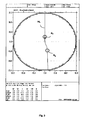
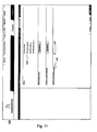
- FIG. 3 a course of the main line HL for an exemplary spectacle lens.
- the far and near reference points are each marked with a circle.
- the character B F denotes the far reference point
- the symbol B F denotes the near reference point.
- isoastigmatism values are shown for the desired astigmatism according to the given start design.
- the far (B F ) and near reference (B N ) for this design are each indicated by a circle.
- the character B z denotes the fitting or centering point.
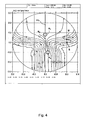
- Fig. 5 is analogous to Fig. 4 an exemplary spectacle lens design, which according to a method according to a preferred embodiment of the present invention from the starting design of Fig. 4 was determined.
- This transformation includes at least partially a compression such that the progression length or channel length has been shortened.
- the point S indicates a point of the startup design.
- the point S is transformed as described above in the point S 'of the derived design.
- the progression zone length is variable at least in a range of 14 to 18 mm.
- an optimization tool for determining or providing the desired values and models is also provided, which comprises a checking module for checking the plausibility of the order parameters.
- Fig. 6 shows an example input interface 10 for inputting desired boundary conditions and / or transformations and / or positions of reference points.
- the input or user interface 10 has a first section 12 for inputting nominal values of the spherical, astigmatic and prismatic effect of the spectacle lens (sphere, cylinder, axis, addition, prism horizontal, prism vertical, prism and base), which can be determined by refraction, for example be determined. All data are preferably based on data in the position of use of the spectacle lens.
- the input / output interface 10 includes a portion 14 for inputting sizing and centering presets (pupil distance, corneal vertex distance, ocular fulcrum distance, ocular pivot point (x, y and z coordinates), angle between the zero gaze direction and the Z axis, decentration ((x, y, and z coordinates), etc.).
- FIGS. 7a and 7b shows an exemplary cross section of a spectacle lens in the position of use, wherein the centering point in the zero direction of the spectacle wearer before the pupil center is arranged.
- the spectacle lens has a spherical effect of 0.00 dpt and an addition of 2.00 dpt. Also is in Fig. 7a and 7b the respective Brechwertverlauf shown along the main line of the lens.
- Fig. 7a shows a spectacle lens according to the prior art
- Fig. 7b a lens with individual position of the far and near reference points.
- the remote reference point B F of in Fig. 7b shown spectacle lens is located 5 mm lower than the distance reference point B F of in Fig. 7a shown spectacle lens.
- FIGS. 4 and 5 Analogous to the FIGS. 4 and 5 are in Fig. 8 and Fig. 9 Further embodiments of transformations according to preferred embodiments of the present invention based on isoastigmatism representations ( Fig. 9 ) or isolines of the refractive power ( Fig. 8 ) of a basic design ( Fig. 8a . 9a ) and a derived individual design ( Fig. 8b . 9b ).
- FIGS. 3 to 5 and FIGS. 8 and 9 is the coordinate system defined above, wherein the coordinate center coincides with the geometric center of the tubular spectacle lens. Further embodiments, advantages and features of the invention will become apparent from the accompanying exemplary and non-limiting description pages.
- the individually definable distance and near reference points are referred to as design point “distance” and design point “proximity”, respectively.
- the individually determined distance reference point or design point “distance” corresponds to the point by which the spectacle lens carrier is optimally corrected when looking into the distance and which corresponds to his personal viewing habits.
- the individually determined near reference point or design point “proximity” corresponds to the point at which the spectacle lens carrier is optimally corrected for near vision tasks and can assume the pleasant lowering of the eye.
- progressive lenses usually have a progressive front surface, while the prescription surface is manufactured on the eye side to the order.
- a limited number e.g., 72
- standardized progressive addition surfaces are used. However, these do not apply to each effect separately, but to a specific spectrum of the impact area.
- the optimization of the progressive power surfaces takes place only for the mean effect per base curve or area of effect. If the refraction data deviate from the optimized effects, this results in restrictions of the usable field of view.
- conventional progressive lenses have limitations in design fidelity, which can lead to incompatibilities with the wearer of glasses.
- optimization of conventional progressive lenses is based only on standard values that often do not do justice to the individuality of the glasses, frames and customer data of the spectacle wearer.
- the disadvantages of the conventional progressive lenses are eliminated by an aspherical or atorical prescription surface optimized individually online for each combination of effects.
- an aspherical or atorical prescription surface optimized individually online for each combination of effects With the free-form technology it is possible to produce effect-optimized progressive lenses.
- custom progressive lenses can also be manufactured with the free-form technology.
- Individual progressive lenses are also known, which are optimized and calculated taking into account the individual regulation (Sph, Zyl, axis, add, prism, base) and the individual position of the lenses in front of the eye (HSA, FSW, anterior tilt, pupillary distance).
- a second group of individual progressive lenses are progressive lenses, which are personalized in another way, e.g. by personal behaviors of the spectacle wearer or his preferences. However, these progressive lenses do not or only partially take into account the individual parameters. These progressive lenses are based on a physionomic standard model, which usually does not agree with the actual conditions and thus causes optical deviations and / or power losses.
- a progressive spectacle lens has been firmly defined so far.
- individual customer parameters eg pupillary distance (PD), corneal vertex distance (HSA), frame shape, front inclination (VN), lens angle (FSW), individual position of the remote - and / or near reference points, individual near distance, etc.
- the customer's viewing experience and needs or visual requirements are incorporated in a preferred method of calculating an individualized design and producing a spectacle lens in accordance with the present invention.
- a preferred method of calculating an individualized design and producing a spectacle lens in accordance with the present invention it is possible, using the technical know-how e.g. of an optician and with the assistance of the customer (spectacle wearer) to design an individual progressive lens.
- advantages and disadvantages of the preceding glass are taken into account.
- the individual parameters eg pupillary distance PD, corneal vertex distance HSA, preadjustment VN, frame disc angle FSW, etc.
- a suitable 3-D measuring device such as by means of the 3-D video centering device ImpressionIST Rodenstock GmbH or alternatively by means of conventional measuring tools are determined, are taken into account in the calculation or optimization of the spatial positions, in particular the vertical and / or horizontal position of the distance and / or the near reference point.
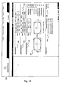
- FIGS. 10 to 12 show graphical user interfaces for entering individual customer parameters.
- a first mask e.g. in a first mask (not shown), information about the customer (e.g., name, contact address, frame selection, etc.) is input or e.g. be taken from a database.
- the selected version which e.g. can also be measured directly or retrieved from a database using a suitable tracer (such as ImpressionIST from Rodenstock).
- Fig. 10 an example of a mask or graphical user interface 120 for inputting individual data (order values) of the spectacle wearer is shown.
- the individual data can be entered directly in the corresponding input fields or sections of the mask or the graphical user interface or, for example, retrieved from a database.
- the gray fields are automatically calculated by the program or filled with data.
- the frame data can be entered in corresponding input fields. These values can be entered automatically when the socket is e.g. is selected by means of a tracer or from a list of versions. If necessary, the centering data can be taken directly from a 3-D video centering system (eg 3-D video centering system from Rodenstock GmbG). With a function "Adapt to box dimension", the version can be adapted to the possibly changed frame data.
- a version can be selected from a database, eg if no socket has been previously recorded or measured by means of a tracer.
- the version may be selected from a list in a pop-up window that opens.
- Shape and frame data are also preferably displayed. The selection can be accepted by confirming.
- an approximated version may be selected from a number of different socket shapes ("approximated shapes"). This may, for example, open another pop-up window in which the socket can be selected from a selection of common shapes.
- the graphical user interface 120 shown also includes an inset section (section 132 ). If the spectacle lens holder exhibits a convergence behavior that deviates from the standard case when looking close, then the value pre-assigned in the "Inset" input field can be suitably changed.
- the inset value is preferably calculated taking into account the individual customer parameters.
- the individual near distance in the refraction determination is 40 cm.
- the ordered addition was determined in 40 cm and also the main viewing distance of the spectacle lens wearer is at this distance.
- the inverse of the addition corresponds to the maximum near distance. If only one of the two input fields "Refraction distance near” or "Main distance near” is filled in, it is assumed that the value also applies to the other distance. The inset and the astigmatism are calculated to the main viewing distance "proximity".
- the individual additional effect for the main viewing distance is automatically calculated as well.
- the individual additional effect is displayed if it is outside the delivery range (0.75 D to 3.50 D) or more than 0.5 D deviates from the order addition.
- the ordered addition of 2.00 D is optimized for 30 cm and the addition is adjusted.
- the astigmatism slanting bundles is also corrected for the desired main visual distance.
- the graphical user interface 120 shown in FIG. 1 also has a section "basic curve" (section 135) in which the base curve best suited for the selected version can be entered.
- the program automatically calculates the most suitable deflection or base curve for the respective refraction data and the respective base curve.
- the base curve calculated by the program may differ from the base curve entered in the input field "Base curve".
- the entered or ordered base curve is automatically checked to the effect that no plan and Konvex vom on the back surface or excessively curved rear surfaces, which may cause particularly high edge thicknesses.
- Fig. 11 shows a mask or graphical user interface 140 for inputting individual data relating to the current or previously worn spectacles.
- this mask information can be made to the previous glass, if this is known.
- it can be selected from a list 142 ("glass type") whether the customer has previously worn a single, multi-level or progressive lens or whether it is the first pair of glasses of the customer (no previous goggles). If a progressive lens was worn, for example, details on the material, the refractive index and / or the progression length can be made in a pop-up menu, for example.
- the progression length of the precursor glass can also be entered automatically based on the choice of the predecessor product or manually. In particular, the progression length of the precursor glass can roughly be classified, for example, as a "standard” or long progression or as a short (“XS”) progression length.
- the addition of the preceding glass can be entered in a designated input field 144 "Addition of the previous glass".
- the addition of the previous lens can be compared with the new addition.
- a hint field eg as a pop-up window
- a hint field may appear indicating the peculiarities of the addition increase.
- FIG. 12 shows an example of a mask or graphical user interface 146 ("design profiler") for entering data regarding the individual preferences of the vision areas.
- a total of 9 points can be distributed over the four different areas (distance, average distance, proximity and active behavior). The more important the customer the distance range is or the more of his activities fall into an area, the more points awarded for this area.
- the number of points per area and the total score can be limited. For example, a maximum of 5 points can be awarded per area, but no more than 9 points in total.
- the points awarded determine the individual design profile of the spectacle wearer. Simplified, the more points awarded to the distance in relation to the given total score, the lower the individual distance reference point, and the more points awarded for proximity in relation to the given total score, the higher the individual's near reference point.
- the points for the active behavior and the vision in medium distances affect first and foremost on the length of the progression zone and thus also determine how distortion-free the spectacle lens is.
- an equal number of points in each area corresponds to a balanced, universal design.
- Fig. 13 shows the location of the far and near reference points of an individual spectacle lens design 148.
- the position of the centering or fitting point is marked by means of a cross 154 (centering cross).
- the distance reference point is in the middle of two round brackets 156 .
- the near reference point is in the middle of the Nahmeß Vietnamese limbals 158th
- the vertical height of the distance reference point may preferably be flexibly determined in a range of +4 to -4 mm relative to the centering or fitting point specified by the manufacturer for this spectacle lens, depending on the individual data of the spectacle wearer.
- the near reference point may preferably be set flexibly between 13 and 20 mm vertically below the centering point. This results in a flexibly selectable progression length, which can preferably be at least 13 mm and a maximum of 24 mm.
- the far and near reference points can be freely set in steps of 0.1 mm within an allowable range. For example, if the remote reference point or -4 mm vertical Height shifted, the near reference point must be at least at a vertical height of -17 mm. If the distance reference point is shifted by +4 mm, the result is a minimum progression length of 17 mm, since the near reference point is preferably displaced no further than -13 mm.
- the minimum vertical distance from the lower edge of the frame to the near reference point is preferably 2 mm.
- the distance reference point preferably has a minimum of a vertical distance of 6 mm, preferably 8 mm from the upper edge of the frame.
- the positions of the distance and near reference points are preferably the same for the right and left lenses. In the case of different viewing heights, however, this can result in disadvantages in the viewing areas for one of the two eyes. So that the viewing areas can be fully utilized for both eyes, it is advantageous to select or set the respectively smaller vertical distance of the near reference point from the centering point.
- Fig. 14 the center point and the far reference point coincide. If the selection of the appropriate vertical position of the near reference point were based on the lower frame edge, for the right eye, a vertical distance of the near reference point from the center point would be -18 mm and for the left eye this distance would be -17 mm. In this case, it is preferable to select the smaller distance.
- the information on the object distances "distance” and “proximity” in the refraction determination are taken into account in the calculation and optimization.
- the beam path corresponding to the actual use situation can be more accurately simulated, and consequently the imaging quality can be improved.
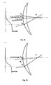
- Fig. 15a illustrates the main viewing distance when looking up close in the actual position of use of the spectacle lens
- Fig. 15b the refraction distance near or the near distance in the refraction determination.
- the addition was determined at a refraction distance near 40 cm (applies to addition 2.50 D, for higher additions 1 / addition) and this corresponds to a main viewing distance in the vicinity of 40 cm. If the main viewing distance differs in the vicinity of the refraction distance in the vicinity, the individual spectacle lens design can be optimized for this main viewing distance.
- a corresponding spectacle lens design is automatically calculated with the thus determined positions of the distance and near reference point and optionally taking into account further individual parameters of the spectacle wearer.
- the design proposal may be made by means of a suitable graphical user interface 160A for presenting results (design recommendation) - as in Fig. 16 shown - visualized.
- a graphical user interface 160B (design tuner) can additionally be shown (cf. Fig. 17 ) by means of which, in addition to a presentation of results, the user is given the possibility of changing the individual position of the distance and / or the near reference point and / or changing the individual data of the spectacle wearer (in particular the preferences, the frame data, etc.). ) to actively change the design.
- the corresponding geometric data of the spectacle lens (center thickness, edge thickness, base curve, weight) can be calculated and also visualized by means of a suitable graphical user interface (preferably in the form of a three-dimensional model).
- the graphical user interfaces 160A and 160B are divided into two areas: in the upper area 162 , information about "seeing” and / or “performance” with the proposed design for an individual spectacle lens; in the lower area 164 information on the topic “appearance” or “geometry” of the individual spectacle lens or glasses shown.
- the edged spectacle lens in particular cosmetic properties or data relating to the aesthetics of the spectacle lens (eg weight, geometric data such as overall height, maximum edge thickness, center thickness, base curve, etc.) of the edged spectacle lens or the edged spectacle lenses can be visualized or represented graphically become.
- the visualization of the cosmetic properties of the spectacle lens can take place, for example, by means of a three-dimensional graphic representation of a model of the spectacle lens 166 with the geometric data determined, such as in FIG Figures 16 and 17 shown.
- the representation of the cosmetic properties of the spectacle lens can be influenced, for example, by a selection of the base curve and the refractive index. The selection can be effect-dependent.
- the "appearance" area 164 may further include a sub-area 168 in which numerical values relating to the geometrical properties of the spectacle lens, such as height, maximum edge thickness, center thickness, weight, base curve of the edged glass, etc., are shown. These values may be approximations, which may differ from the actual glass geometry data.
- the individually determined distance and near reference points can also be shown as stamp points.
- views 169 of the edged spectacle lenses can be shown from different static perspectives (version from above, version from the front, from the side, obliquely from above).
- the gerandeten eyeglass lenses in the selected view are displayed dynamically rotating.
- the picture can be enlarged, eg via a corresponding button.
- the "appearance" area 164 further includes a portion 170 for displaying numerical values for refractive index and a section for displaying the base curve (section 172 ).
- the displayed values for the base curve and the refractive index are composed of the effective range, the required diameter, the base curve and the refraction data. Therefore, deviations from the base curve command entered in the "Order values" mask are possible.
- the technically feasible values for base curve and refractive index of the glass can be changed by means of corresponding selection fields. If changes are made to the base curve specification, the refractive index, etc., the graphic and the geometry data can be recalculated according to the changed values, eg by clicking on an "Update" button.
- the area "see” 162 of the graphical user interfaces 160A and 160B is therefore basically subdivided into several subregions or subregions.
- “Binocular View Area Representation" of the area 162 becomes For example, the ideal design for the customer and the specified version is shown schematically using an ellipse. Gray areas are subject to aberrations (eg astigmatism in use position greater than 0.5 dpt) afflicted areas. In addition, if necessary, the course of the 0.5 d isoastigmatism line can be shown. The vertical heights of the distance and near reference points can each be identified by (optionally differently colored) lines 175, 176 . In the sub-area 177 of the area 162 , numerical values for the spatial location (in particular for the vertical altitude with respect to the centering point) of the far and near reference points are shown.
- the optician / optometrist and / or the spectacle wearer can be given the opportunity to actively change the thus calculated individual spectacle lens design.
- the change takes place, for example, in that the spatial position, in particular the vertical height of the distance and / or the near reference point, is actively changed.
- the weights of the viewing areas can be changed.
- the change or adaptation of the position of the distance and / or the near reference point and / or the preferences with regard to the viewing areas can be, for example by means of a suitable graphical user interface.
- An example of a suitable graphical user interface in the form of sliders 180 is shown in FIG Fig. 17 shown. With the in Fig. 17 shown slider 180 is a direct adjustment of the position of the far and / or near reference point possible.
- the new spectacle lens design with the changed position of the distance and / or the near reference point is preferably calculated and visualized in real time.
- the difference or the change in the optical properties of the new compared to the old spectacle lens design is also visualized.
- the design recommendation ( Fig. 16 ) an ellipse are displayed, which corresponds in the box dimensions and the predetermined centering of the approximated binocular customer version.
- the proposed, individual design can be changed here, for example, by sliding the slider for the distance and the near reference point up or down.
- the numerical values for the position of the reference points change accordingly.
- the lines for the far and near reference points shift.
- color (eg yellow) visual range lines eg 0.5 dpt I soastigmatism line
- the ratio of the size of the viewing areas to each other and the length of the "Dynamics" bar change.
- the awarded points in the section “Designprofiler” are preferably not influenced by the changes in the section “Designtuner”.
- Example 1 Eyeglass Glass Architect:
- the eyeglass wearer attaches great importance to a wide intermediate area and wants a "rather quiet" lens with a few rocking movements, as he has to see for professional reasons, the majority of the day in the intermediate range (medium distances). In his present glasses he wears a progressive lens with a progression zone length of 18 mm.
- the program recommends setting the distance reference point to +2.4 mm above the centering or fitting point for the selected frame and corresponding centering.
- the near reference point would be optimally at -19 mm below the centering or fitting point.
- the program recommends laying the distance reference point to 1.5 mm above the centering or fitting point for the selected version and corresponding centering.
- the near reference point would be optimally -15.5 mm below the centering or fitting point.
- the editor has a good compromise from wider close range and relaxed head posture.
- the program recommends the remote reference point depending on the other input parameters move upwards.
- the distance reference point would then be above the centering or fitting point.
- a "fogging" in the centering or fitting point of up to +0.25 D can result in these cases.
- lateral restrictions in the far range may also arise, since the spectacle lens carrier - in the case of a shift of the distance reference point upwards - sees in zero viewing direction through the progression already beginning earlier in the spectacle lens.
- the spectacle lens carrier receives a spectacle lens design or spectacle lens designed or optimized according to its individual viewing habits.
- the eyeglass wearer attaches particular importance to a large distance range, because he spends most of the day with vision in the distance for professional reasons.
- the program calculates automatically and recommends for this customer to set the remote reference point to -2.5 mm below the centering or fitting point for the selected version and corresponding centering.
- the near reference point would be optimally at -18.4 mm below the centering or fitting point.
- the lens carrier has a large distance range and a good compromise of low rocking movements and well exploitable intermediate and close range.
- the spectacle wearer wears progressive lenses with a normal progression zone length. Since there are no preferences and the activities of this customer are distributed equally in the areas of distance, middle distance and proximity, the same number of points are awarded for all distances and also for the active behavior or dynamics. In other words, all areas of vision and dynamic behavior or properties are equally weighted. In the concrete example, for all areas of the in Fig. 12 awarded "Design profiler" each 2 points.
- the "Design Recommendation" graphical user interface displays the result of the calculations taking into account the individual inputs to the previous screens. The program automatically calculates and recommends for this customer the distance reference point to 0 mm and the near reference point to -18 mm.
- This spectacle lens would correspond to a balanced, universal progressive spectacle lens with a progression zone length of 18 mm (eg a spectacle lens of the previous "Impression ILT®” from Rodenstock GmbH), since in the design interpretation it is assumed that no area of activity is recognizable in one of the distance ranges.
- the eyeglass wearer wears progressive lenses with normal progression zone length (PZL).
- PZL progression zone length
- the preference of the spectacle wearer is clearly in the distance, the mean distance and the proximity play a subordinate role. Therefore, for this example, 4 points were awarded for distance, 1 point for middle distances and nearness (cf. Fig. 12 ).
- the active behavior and dynamics of the in Fig. 12 Weighted "Designprofiler” weighted with 3 points.
- the "Design Recommendation" graphical user interface displays the result of the calculations taking into account the individual inputs to the previous screens.
- the program automatically calculates and recommends for this customer the distance reference point to -1.1 mm and the near reference point to -18.5 mm.
- the largest possible remote area is realized for the individual requirements of the customer.
- the spectacle lens offers a vision similar to that of a star and is virtually distortion-free. This has a positive effect eg on the sporty leisure activities of the spectacle wearer.
- the most important distance for this spectacle wearer is therefore the middle distance, also the proximity is important for him, the distance and the active behavior play a subordinate role. Therefore, in the in Fig. 12 "Designprofiler" for the distance and for the active behavior assigned 1 point each, 3 points for medium distances and 2 points for the proximity shown.
- the "Design Recommendation" graphical user interface displays the result of the calculations taking into account the inputs to the previous screens. The program calculates automatically and recommends positioning the remote reference point +0.7 mm and the near reference point to -18.1 mm for this customer. Thus, the largest possible intermediate area is realized. Due to the location of the near reference point and the associated relatively long progression zone length, the spectacle lens offers a vision similar to that of a star and is virtually distortion-free. This benefits the spectacle wearer when working with drawings.
- the most important distance for this eyeglass lens is therefore the proximity.
- the average distance is important, the distance and the active behavior play a minor role. Therefore, in the in Fig. 12 "Designprofiler" for the proximity shown 4 points, for the middle distance 2 points and 1 point each for the distance and the active behavior assigned.
- the "Design Recommendation" graphical user interface displays the result of the calculations taking into account the inputs to the previous screens.
- the program automatically calculates and recommends positioning the far reference point at +0.8 mm and the near reference point at -17.0 mm.
- the greatest possible intermediate and close range is realized for the individual requirements of the spectacle wearer. Due to the position of the near reference point, the desire of the spectacle wearer is implemented in her individual progressive lens after a pleasant eye-drop for near vision tasks.
- the individual data of the spectacle wearer can also be detected by means of suitable order forms and forwarded to the spectacle lens manufacturer.
- Fig. 18 shows an example order form.
- the acquired individual refraction data sphere, cylinder, axis, prism, base
- frame and centering data individual parameters of the eyes of the wearer and the individual position of use (pupil distance, lens angle, preadjustment, corneal vertex distance, etc.) and possibly others individual data indicated.
- the order form it is possible to choose the positions of the distance and / or near reference points so that they correspond to the positions of a universal progressive lens design (eg Impression ® or Impression XS ® of the company Rodenstock GmbH). It is also possible to define a mean progression zone length of 16 mm.
- the positions of the far and / or near reference points may be determined depending on the individual frame data (frame optimized design). For example, the distance reference point at the center point (ie at 0 mm) and the near reference point at 2 mm above the bottom edge of the frame can be specified.
- the position of the distance and near reference points may also be individually determined taking into account further individual data (eg, areas of activity and preferences regarding the areas of vision) as described in detail above.
- an individual spectacle lens is optimized or calculated, the optimization taking into account at least part of the determined individual data, in particular data regarding the individual parameters of the spectacle wearer and the individual use position (lens angle, preadjustment, pupil distance, corneal vertex distance, etc.,) takes place.
- the ray tracing method is used to describe optical images.
- the calculation of a spectacle lens with ray tracing is very time-consuming, since for each point in the spectacle lens, in addition to the actual light beam or main beam, an "accompanying" bundle of neighboring rays must also be simulated through the spectacle lens.
- the individual spectacle lens is calculated by means of a wavefront tracing method, in particular by means of a local wavefront optimization.
- Wave fronts can be used as well as light rays to describe or calculate optical images.
- a wavefront is the area of equal phase of a propagating wave.
- Each such wavefront summarizes all the properties of a bundle of neighbor rays in a single object.
- the calculation time can be significantly reduced, so that an individual optimization of each individual spectacle lens is made possible.
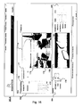
- Fig. 19 shows a schematic representation of the physiological and physical model of a spectacle lens in a predetermined position of use, which is based on the individual lens calculation or optimization.
- Fig. 19 It can be seen that the rays from an infinitely distant object 184 are all parallel, which is reflected in a plane wavefront 186 . In contrast, the rays emanating from a nearby object 188 diverge. Accordingly, the wavefront 190 is curved.
- the spectacle lens which has a preferably spherical front surface 192 and an individual calculated progressive-atoric back surface 194 , must now ensure that each wavefront 196 , 198 on the eye side is preferably curved so that the corresponding object 184 , 188 is focused on the retina of the eye 200 is imaged. Ideally, these wavefronts must be equally curved on the eye side for all directions of view.
- the spectacle lens In order to calculate the spectacle lens, it is preferable to use a flexible surface design of the individually calculable progressive surface with a plurality of evaluation sites (preferably over 7000 assessment sites), each of these evaluation sites being assigned its own local wavefront computation.
- the individual progressive surface is preferably determined by minimizing an objective function which is evaluated at the evaluation sites, and taking into account optimized physiological model. In this way, it is possible to carry out the optimization of a spectacle lens according to the variable objective function very quickly and thus online after the receipt of the order by means of individual wave front calculations.
- the calculation of the spectacle lens preferably comprises an optimization with more than 2000 optimization parameters in a high-dimensional space.
- Multiprocessor mainframes can be used for real-time online optimization.
- the spectacle lens Preferably, in the individual optimization of the spectacle lens, not only low order aberrations (sphere, cylinder, prism) but also higher order aberrations (eg, coma and spherical aberration) are minimized.
- low order aberrations sphere, cylinder, prism
- higher order aberrations eg, coma and spherical aberration
- US Pat. No. 7,063,421 B1 directed.
- the production of the individually calculated spectacle lens takes place, for example, by means of precision machines, preferably CNC grinding and polishing machines, which can convert the calculated area data with an accuracy in the ⁇ m range.
- Figures 20 a and b respectively represent schematic illustrations of the axial positions in a spectacle lens without consideration of Listing's rule ( Fig. 20a ) and with consideration of Listing's rule ( Fig. 20b ).
- an individual predecentration is preferably taken into account in the optimization and calculation of the individual progressive spectacle lens.
- the optimum pre-concentration can be calculated automatically based on data regarding the frame or spectacle lens shape as well as data relating to the centering.
- an individual pre-concentration may be determined by the optometrist / optometrist himself.
- the desired diameter determined by means of a special centering card can also be taken into account.
- a pre-concentration of up to 5 mm can be taken into account.
- the individually calculated spectacle lens preferably has a spherical or rotationally symmetrical aspherical object-side front surface and an individual depending on the individually determined reference or design points distance and proximity, the individual refraction data, the individual parameter of the spectacle wearer and the situation of use (eg pupil distance, front inclination, frame disc angle . Corneal vertex distance, etc.) optimized progressive, eye-side freeform surface.
- the position of the individual far and near reference points is preferably recorded by means of individual stamping by means of non-permanent markings.
- the position of the individual far and near reference points can furthermore be clearly reconstructed on the basis of permanent markings or microgravures of the spectacle lens and a reconstruction rule (template, centering card).
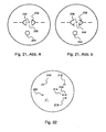
- Fig. 21 a, b show examples of non-permanent stamping of two individual progressive spectacle lenses.
- the non-permanent marking or the stamp of an individually optimized according to a preferred method according to the invention spectacle lens consists of "movable” and “fixed” components.
- the moving parts include two round brackets 202 , which indicate the location of the remote reference point and the design point Far, respectively, and the proximity measuring circuit 204 , which marks the position of the near reference point or the design point "Proximity".
- the far reference point is at the center of the round brackets 202 and the near reference point is at the center of the proximity circuit 204 .
- the stamp of an individual spectacle lens can therefore look different.
- a cross 206 centering cross
- the prism reference point 208 is normally 4 mm below the centering point. In the case of higher anisometropia and customer wishes with regard to a specific weighting (for example, if the prismatic vertical differences are to be adjusted in the near range), a prism adjustment point can be shifted in the desired direction.
- the distance reference point is at the level of the centering point.
- the near reference point is at a vertical height of -18 mm below the centering point.
- Fig. 21b is shown another example of an individual stamp or an individual stamp image of an individual spectacle lens.
- the eyeglass lens is individually calculated and optimized for a wearer of eyeglasses, which places "great value on a long distance range.”
- the distance reference point lies at a vertical height of -4 mm below the centering or fitting point and the near reference point lies at a vertical height of -18 mm below the centering or fitting point.
- the values for the position of the distance and near reference points are also permanently engraved in the spectacle lens.
- the stamp may differ from the one described above.
- an explicit non-permanent marking of the positions of the distance and near reference points and / or the centering or fitting point may be missing.
- the reference points can be determined unambiguously by means of a reconstruction rule comprising a centering card, stamped scales in 1 mm increments and a glass bag.
- the spectacle frame with the marked centering point is placed on the centering cross of the centering card and the position of the distance and near reference points drawn on the spectacle lens.
- the position of the far and near reference points can also be determined using the permanently engraved values below the nasal base curve and index engraving.
- the individual spectacle lens also has permanent (micro) engravings.
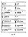
- Fig. 22 shows the permanent engraving of an individually optimized left lens viewed from the back (ie from the eye side).
- the functional engraving or the permanent mark for the alignment of the spectacle lens is the infinity sign.
- the two function engravings 210 , 212 are located at a distance of 34 mm from each other at the height of the centering point or centering cross.
- Below the nasal infinity sign 212 are the two-digit base curve engraving 214 and index engraving 216, respectively.
- Underneath is the engraving 218 for the location of the distance and near reference points.
- the first number indicates the vertical distance of the distance reference point relative to the centering or fitting point.
- the second number indicates the vertical distance of the near reference point relative to the centering or fitting point.
- the distance reference point may preferably be in a range between -4 and +4 mm located below or above the centering point.
- the near reference point may preferably be in a range between -13 and -20 mm below the centering or fitting point.
- the finished and stamped spectacle lens is packed in a glass bag and delivered to the optician / customer.
- An example of a glass bag is in Fig. 23 shown.
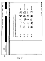
- Fig. 24 shows a list of the pictograms or symbols used on the glass bag.
- the relevant data for a correct grinding in the spectacle frame in particular data relating to the frame or disc shape, can be found on the glass bag.
- the corrected pupillary distance PD for grinding (COR PD) is calculated. This is necessary to get the right customer PD in the finished glazed glasses. Also for eyeglass lenses with correction prism the COR PD should be used instead of the customer PD for grinding in, if the form was given.
- the necessary centering correction for prisms with horizontal and vertical base position has already been considered in the calculation of the lenses. The value for the centering correction on the glass bag is therefore always zero.
- the COR PD can not be calculated because the parameters required for their calculation (frame and centering data) are not transmitted.
- the centering correction for prisms with a horizontal and vertical base position is preferably already taken into account in the calculation of the lenses.
- the value for the centering correction on the glass bag remains zero. This value refers to an order without form specification on the PD.
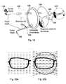
- Figures 25 a and b illustrate the centering of a progressive spectacle lens in front of the eyes of the wearer and the corresponding position of the reference points.
- the spectacle lens shown is an individual spectacle lens with positions of the distance and near reference points determined individually according to a preferred method according to the invention.
- This in Fig. 25b shown spectacle lens is a standard spectacle lens.
- the individually calculated progressive lenses are adjusted according to the reference point requirement. This means that the centering point or fitting point (or the centering cross) should lie at the center of the pupil in the direction of zero sight in habitual head and body posture.
- the minimum grinding height depends on the position of the near reference point. Preferably, at least 2 mm remain below the near reference point in the socket. The minimum grinding height is thus preferably 15 mm below the centering point. If progressive lenses are adjusted differently from the centering recommendation, the imaging properties may be restricted.
- the main viewing areas are arranged so individually that they coincide with the respective main direction of vision.
- the so-called nominal measured values are also measured in the reference points, with the desired measured values being indicated next to the order values on the glass bag of the individual spectacle lens.
- the desired measured values preferably relate to the concave peak measurement position. Tolerance considerations refer to the target measured values, not to the order values.
- the nominal measured values for sphere, cylinder and axis are checked at the remote reference point.
- This distance reference point is individually different, preferably within a range of +4 to -4 mm, about the center point.
- the exact location of the far reference point can be found in the additional engraving below the base curve and index engraving.
- the measurement of the remote part effect is in Fig. 26a shown schematically.
- a combined effect of thickness reduction prism (base position always 270 °) and correction prisms is measured.
- the measurement of the prismatic effect is in Fig. 26b shown schematically.
- the near reference point is individually different within a range from -13 to -20 mm below the centering point.
- the exact location of the near reference point can be found in the additional engraving below the base curve and index engraving.
- the measurement of the proximity is in Fig. 26c shown.
- the nominal value of the addition corresponds to the difference between the mean effect (spherical equivalent) between the distance and near reference points. In many cases, however, it is easier and generally sufficient to check the match of ordered and engraved additions.
- the spectacle lens design determined individually as a function of customer needs and parameters has characteristic features of a balanced, universal spectacle lens design, i. maximum viewing areas for all distances with harmonious transitions between the central and peripheral visual areas.
- a design or spectacle lens thus provides optimal visual comfort for a wide range of situations in everyday life (driving, leisure activities, reading, etc.).
Abstract
Description
Die Erfindung betrifft ein Verfahren zum Berechnen eines individuellen Brillenglasdesigns, ein Verfahren zum Herstellen eines individuellen progressiven Brillenglases, sowie eine entsprechende Vorrichtung zum Herstellen eines individuellen Brillenglases, ein Computerprogrammerzeugnis, ein Speichermedium und eine Verwendung eines Brillenglases.The invention relates to a method for calculating an individual spectacle lens design, a method for producing an individual progressive spectacle lens, and a corresponding device for producing an individual spectacle lens, a computer program product, a storage medium and a use of a spectacle lens.
Die Berechnung und Optimierung von Gleitsichtbrillengläsern in der jeweiligen Gebrauchsstellung bzw. Gebrauchssituation hat mittlerweile einen hohen technischen und optischen Standard erreicht. So können nach dem Stand der Technik Gleitsichtbrillengläser unter Berücksichtigung der individuellen Verordnung (sph, Zyl, Achse, Add, Prisma, Basis) und der individuellen Lage bzw. Anordnung der Gläser vor dem Auge des Brillenträgers (z.B. Hornhautscheitelabstand (HSA), Fassungsscheibenwinkel (FSW), Vorneigung bzw. pantoskopischer Winkel) und Berücksichtigung von physiologischen Parametern (z.B. Pupillendistanz) online nach Bestelleingang als Unikat optimiert und berechnet werden. Die Positionierung des Brillenglases zum Kundenauge, d.h. in der Brillenfassung, wird jedoch vom Hersteller fest vorgegeben (z.B. durch die Bezugspunktforderung) und kann nicht variiert werden. Ebenso kann der Kunde nur aus wenigen (meistens 2) Brillenglasdesigns auswählen, welche sich dann nur durch die Progressionslänge unterscheiden. Eine Anpassung der Sehbereiche an besondere Kundenwünsche bezüglich individueller Hauptblickrichtungen und Anwendungsschwerpunkte gekoppelt mit einer bestimmten, eventuell limitierenden, Fassungswahl ist bisher nicht möglich.The calculation and optimization of progressive power lenses in the respective position of use or use has now reached a high technical and optical standard. Thus, according to the state of the art, progressive lenses can be made taking into account the individual prescription (sph, cyl, axis, add, prism, base) and the individual position or arrangement of the lenses in front of the wearer's eye (eg corneal vertex distance (HSA), frame disc angle (FSW ), Inclination or pantoscopic angle) and consideration of physiological parameters (eg pupil distance) can be optimized and calculated online after receipt of order as a unique specimen. The positioning of the lens to the customer's eye, i. in the spectacle frame, however, is fixed by the manufacturer (e.g., by the reference point requirement) and can not be varied. Likewise, the customer can only select from a few (usually 2) lens designs, which then differ only by the progression length. An adaptation of the viewing areas to special customer wishes regarding individual main directions of vision and application focuses coupled with a specific, possibly limiting, frame selection is not yet possible.
Nach dem Stand der Technik werden ferner für jedes neu zu entwickelnde Design und speziell auch für jede Progressionszonenlänge eigene Sollvorgaben (Designs) erarbeitet und hinterlegt. So werden neben den Universalgleitsichtgläsern auch für diverse Spezialgleitsichtgläser Designs entwickelt, die sich häufig im Wesentlichen nur bezüglich der Hauptssehaufgaben und damit bezüglich der Hauptblickrichtungen im Fern- und im Nahbereich unterscheiden. In der
Die Druckschrift
Die Druckschrift
Die Druckschrift
Aufgabe der Erfindung ist es, ein schnelles und effizientes Verfahren zum Berechnen eines individuellen Brillenglasdesigns sowie ein Verfahren zum Herstellung eines Brillenglases nach dem individuell berechneten Brillenglasdesign bereitzustellen. Es ist ferner eine Aufgabe der Erfindung eine entsprechende Vorrichtung zum Herstellen eines individuellen Brillenglases sowie entsprechende Computerprogrammerzeugnis und Speichermedium bereitzustellen.The object of the invention is to provide a fast and efficient method for calculating an individual spectacle lens design as well as a method for producing a spectacle lens according to the individually calculated spectacle lens design. It is a further object of the invention to provide a corresponding apparatus for producing an individual spectacle lens as well as corresponding computer program product and storage medium.
Diese Aufgabe wird durch ein Verfahren zum Berechnen eines individuellen Brillenglasdesigns mit den Merkmalen gemäß Anspruch 1, ein Verfahren zum Berechnen eines individuellen Brillenglasdesigns mit den Merkmalen gemäß Anspruch 28, ein Verfahren zum Herstellen eines individuellen progressiven Brillenglases mit den Merkmalen gemäß Anspruch 31, eine Vorrichtung zum Herstellen eines individuellen Brillenglases mit den Merkmalen gemäß Anspruch 32, ein Computerprogrammerzeugnis mit den Merkmalen gemäß Anspruch 33, ein Speichermedium mit den Merkmalen gemäß Anspruch 34 sowie eine Verwendung eines Brillenglases mit den Merkmalen gemäß Anspruch 35 gelöst. Bevorzugte Ausführungsformen sind Gegenstand der Unteransprüche.This object is achieved by a method for calculating an individual spectacle lens design with the features according to
Gemäß der Erfindung wird ein computerimplementiertes Verfahren zum Berechnen eines individuellen Brillenglasdesigns für ein progressives Brillenglas mit einer variabel einstellbaren, individuellen vertikalen Position des Fern- und/oder Nahbezugspunkts bereitgestellt, wobei das Verfahren folgende Schritte umfaßt:
- Vorgeben eines Startdesigns, welches eine vorgegebene vertikale Position des Fern- und/oder des Nahbezugspunkts aufweist;
- Berechnen des individuellen Brillenglasdesigns derart, daß dieses die geforderte, individuelle vertikale Position des Fern- und/oder Nahbezugspunkts aufweist, wobei die Berechnung des individuellen Brillenglasdesigns eine Berechnung einer Sollvorgabe SSoll (y) für die räumliche Verteilung mindestens einer optischen Eigenschaft des individuellen Brillenglases mittels einer Zuordnung SSoll (y)=S'Soll (y') und einer Transformation Y: y ↦ y', y ↦ y'(y) = y - Δy(y) einer entsprechenden Sollvorgabe S'Soll (y') des Startdesigns umfaßt, wobei y' die vertikale Koordinate der Sollvorgabe des Startdesigns und y die vertikale Koordinate der transformierten Sollvorgabe des individuellen Brillenglasdesigns bezeichnen.
- Specifying a startup design having a predetermined vertical position of the far and / or near reference points;
- Calculating the individual spectacle lens design in such a way that it has the required individual vertical position of the distance and / or the near reference point, the calculation of the individual spectacle lens design calculating a target specification S Soll ( y ) for the spatial distribution of at least one optical property of the individual spectacle lens an assignment S setpoint ( y ) = S ' setpoint ( y' ) and a transformation Y : y ↦ y ', y ↦ y ' ( y ) = y - Δ y ( y ) of a corresponding setpoint specification S ' setpoint ( y' ) of the startup design, where y 'denotes the vertical coordinate of the target designation of the startup design and y the vertical coordinate of the transformed designation of the individual lens design.
Die vertikale Richtung bezieht sich vorzugsweise auf die vertikale Richtung in Gebrauchsstellung des Brillenglases, wobei das Brillenglas beispielsweise in einer durchschnittlichen (wie z.B. in DIN 58 208 Teil 2 definiert) oder in einer individuellen Gebrauchsstellung angeordnet ist. Vorzugsweise ist das Brillenglas in einer individuellen Gebrauchsstellung angeordnet.The vertical direction preferably refers to the vertical direction in the position of use of the spectacle lens, the spectacle lens being arranged, for example, in an average (as defined for example in DIN 58 208 Part 2) or in an individual use position. Preferably, the spectacle lens is arranged in an individual use position.
Das Koordinatensystem ist vorzugsweise ein Koordinatensystem in der objektseitigen Fläche des Brillenglases, wobei der Ursprung des Koordinatensystems beispielsweise mit dem geometrischen Mittelpunkt des (rohrunden) Brillenglases oder mit dem Zentrier- bzw. Anpaßpunkt des Brillenglases zusammenfällt. Die vertikale und horizontale Achse liegen in der tangentialen Ebene zu der objektseitigen Fläche in dem geometrischen Mittelpunkt bzw. dem Zentrier- bzw. Anpaßpunkt. Es ist selbstverständlich möglich, die Transformation in anderen geeigneten Koordinatensystemen zu definieren.The coordinate system is preferably a coordinate system in the object-side surface of the spectacle lens, wherein the origin of the coordinate system coincides, for example, with the geometric center of the (tubular) spectacle lens or with the centering or fitting point of the spectacle lens. The vertical and horizontal axes lie in the tangential plane to the object-side surface in the geometric center or the centering or fitting point. It is of course possible to define the transformation in other suitable coordinate systems.
Das Design eines Brillenglases umfaßt die Verteilung der Soll-Werte für eine oder mehreren optische Eigenschaften bzw. Abbildungsfehler, welche in die Optimierung des Brillenglases als Zielwerte eingehen, und gegebenenfalls ein geeignetes Objektmodell. Das Objektmodell kann beispielsweise eine Objektabstandsfunktion, welche als die reziproke Objektentfernung entlang der Hauptlinie des Brillenglases definiert ist, umfassen. Ein Beispiel eines geeigneten Objektmodells ist in DIN 58 208 Teil 2 (vgl. Bild 6) definiert. Ebenfalls ist in DIN 58 208 Teil 2 eine normierte Gebrauchsstellung definiert.The design of a spectacle lens comprises the distribution of the desired values for one or a plurality of optical properties or aberrations, which enter into the optimization of the spectacle lens as target values, and optionally a suitable object model. The object model may include, for example, an object distance function defined as the reciprocal object distance along the principal line of the spectacle lens. An example of a suitable object model is defined in DIN 58 208 Part 2 (see Figure 6). Also, a standardized use position is defined in DIN 58 208
Um Gleitsichtgläser mit unterschiedlichen Designs (d.h. mit unterschiedlichen Sollvorgaben für die Abbildungsfehler, insbesondere für die astigmatische Abweichung) zu erzeugen, müssen die entsprechenden unterschiedlichen Design- bzw. Sollvorgaben erzeugt und damit die Optimierungen durchgeführt werden.In order to produce progressive lenses with different designs (i.e., with different target values for the aberrations, in particular for the astigmatic aberration), the corresponding different design or target specifications must be generated and thus the optimizations must be carried out.
Ein Brillenglasdesign wird insbesondere durch die Verteilung des Refraktionsfehlers (d.h. die Differenz des Brechwerts des Brillenglases von dem Brechwert, welcher mittels Refraktionsbestimmung ermittelt wird) und/oder die Verteilung des Astigmatismusfehlers bzw. der astigmatischen Abweichung (d.h. die Differenz des Astigmatismus des Brillenglases von dem Astigmatismus, welcher mittels Refraktionsbestimmung ermittelt wird) charakterisiert. Ferner kann ein Brillenglasdesign ebenfalls die Verteilung der Soll-Werte für Vergrößerungs-, Verzerrungs- oder anderen Abbildungsfehler umfassen. Dabei kann es sich um Flächenwerte oder vorzugsweise um Gebrauchswerte, d.h. Werte in Gebrauchsstellung des Brillenglases handeln. Berechnen eines individuellen Brillenglasdesigns in diesem Sinne umfaßt die Berechnung der Sollvorgaben bzw. der Sollwerte für die einzelnen optischen Eigenschaften bzw. Abbildungsfehler (z.B. Refraktionsfehler, astigmatische Abweichung, Vergrößerung, Verzerrung, etc.), welche dem individuellen Brillenglasdesign zuzuordnen sind.A spectacle lens design is characterized in particular by the distribution of the refractive error (ie the difference of the refractive power of the spectacle lens from the refractive power, which is determined by means of refraction determination) and / or the distribution of the astigmatism error or astigmatic deviation (ie the difference of the astigmatism of the spectacle lens from the astigmatism , which is determined by means of refraction determination). Further, eyeglass lens design may also include distributing the desired values for magnification, distortion, or other aberrations. These may be area values or, preferably, utility values, i. Values act in the position of use of the spectacle lens. Calculating an individual spectacle lens design in this sense involves calculating the target values for the individual optical characteristics or aberrations (e.g., refractive error, astigmatic aberration, magnification, distortion, etc.) attributable to the individual spectacle lens design.
Ein progressives Brillenglasdesign umfaßt in der Regel einen Fern-, einen Nah- und einen Zwischen- bzw. Progressionsbereich. Die 0,5-Dpt. Astigmatismuslinie wird in der Regel zur Abgrenzung der einzelnen Sehbereiche gegenüber der Peripherie herangezogen. Es ist jedoch möglich andere Isoastigmatismuslinien, wie z.B. die 0,75 oder 1,0 dpt Isoastigmatismusline, zur Abgrenzung der Sehbereiche heranzuziehen.A progressive spectacle lens design typically includes a distance, a near and an intermediate or progression area. The 0.5 Dpt. As a rule, the astigmatism line is used to delimit the individual visual areas from the periphery. However, it is possible to use other isoastigmatism lines, such as the 0.75 or 1.0 d isoastigmatism line, to delineate the areas of vision.
Ein Design weist eine vorgegebene räumliche Position des Fern- und/oder Nahbezugspunkts auf, wenn in dem jeweiligen Bezugspunkt die vorgeschriebenen bzw. für den Brillenträger erforderlichen Werte für die Fern- und/oder Nahteilwirkungen (welche z.B. mittels Refraktionsbestimmung ermittelt werden) erreicht werden. Anders ausgedrückt sollen im Fern- und/oder Nahbezugspunkt die dem Design zugeordneten Sollvorgaben für die Abbildungsfehler (insbesondere astigmatische Abweichung und Refraktionsfehler) möglichst klein (vorzugsweise im wesentlichen Null) sein.A design has a predetermined spatial position of the distance and / or the near reference point if the prescribed or required values for the distance and / or near-field effects (which are determined, for example, by means of refraction determination) are achieved at the respective reference point. In other words, at the distance and / or near reference point, the target specifications for the aberrations (in particular astigmatic deviation and refraction error) assigned to the design should be as small as possible (preferably substantially zero).
Gemäß der Erfindung können die neuen Sollvorgaben bzw. die Sollvorgaben des individuellen Brillenglasdesigns aus bereits hinterlegten älteren Sollvorgaben bzw. Sollvorgaben des Startdesigns transformiert werden, d.h. die neuen Sollvorgaben an der Stelle y gehen aus den alten Sollvorgaben an der Stelle y' hervor, wobei ![]()
![]()
Die Transformation der Sollvorgaben findet lediglich in vertikaler Richtung (y-Richtung) statt. In horizontaler Richtung findet keine Transformation der Sollvorgaben des Startdesigns statt. In diesem Sinne ist der Ausdruck SSoll (y) als eine verkürzte Schreibweise für SSoll(x, y) und der Ausdruck S'Soll (y') als eine verkürzte Schreibweise für S'soll (x, y') zu verstehen. Alternativ können die Sollvorgaben anstatt im Koordinatensystem {x, y} im Koordinatensystem {u, y} vorgegeben werden, wobei u den horizontalen Abstand von einer vorgegebenen Hauptlinie bezeichnet. In diesem Koordinatensystem entspricht der Ausdruck Ssoll (y) dem Ausdruck SSoll (u, y) und der Ausdruck S'Soll (y') dem Ausdruck S'Soll (u, y').The transformation of the target specifications takes place only in the vertical direction (y-direction). In the horizontal direction, there is no transformation of the target specifications of the start design. In this sense, the term S target (y) is provided as a shortened notation for S target (x, y) and the expression S 'target (y') as a shortened notation for S 'to (x, y' to understand). Alternatively, the target values can be specified instead of in the coordinate system { x , y } in the coordinate system { u , y }, where u denotes the horizontal distance from a given main line. In this coordinate system the expression S soll ( y ) corresponds to the expression S Soll ( u, y ) and the expression S ' Soll ( y' ) corresponds to the expression S ' Soll ( u, y' ).
Dementsprechend enthält das Startdesign vorzugsweise Vorgaben für den Verlauf einer Hauptlinie und das Berechnen des individuellen Brillenglasdesigns eine Transformation der Hauptlinie. Die x-Koordinate der transformierten Hauptlinie wird aus der vorgegebenen Hauptlinie des Startdesigns beispielsweise wie folgt berechnet: ![]()
wobei ![]()
x 0(y') die x-Koordinate der vorgegebenen Hauptlinie des Startdesigns für den y-Wert y' ist; und
x 0(y) die x-Koordinate der transformierten Hauptlinie für den y-Wert y bezeichnen.Accordingly, the startup design preferably includes guidelines for the progression of a main line and calculating the individual spectacle glass design a transformation of the main line. The x-coordinate of the transformed main line is calculated from the given main line of the start-up design, for example, as follows: ![]()
in which ![]()
x 0 ( y ' ) is the x-coordinate of the given main line of the start-up design for the y-value y '; and
x 0 ( y ) denotes the x coordinate of the transformed main line for the y value y .
Mit dem erfindungsgemäßen Verfahren kann so aus einem bestehenden Gleitsichtglasdesign (Startdesign) direkt ein Gleitsichtglas mit beliebiger vertikaler Lage der Bezugspunkte für die Ferne und die Nähe (Fern- und Nahbezugspunkt) und Hauptsehbereiche unter Beibehaltung der Designcharakteristik abgeleitet und optimiert werden. Hierzu genügt es, lediglich die gewünschte individuelle Lage des Fernbezugspunkts BF und/oder des Nahbezugspunkts BN (auch nachfolgend jeweils Bezugspunkte für Ferne BF und Nähe BN genannt) vorzugeben. Die vertikale Position und Länge der Progressionszone der Gleitsichtfläche wird automatisch an die individuelle Benutzersituation angepaßt. Dabei kann eine beliebige Position der Bezugspunkte für Ferne BF und Nähe BN bei der Optimierung des Brillenglases berücksichtigt werden.With the method according to the invention, a progressive lens design with an arbitrary vertical position of the reference points for the distance and the proximity (distance and near reference point) and main viewing areas can thus be directly derived and optimized from an existing progressive lens design (start design) while maintaining the design characteristic. For this purpose, it is sufficient to specify only the desired individual position of the distance reference point B F and / or the near reference point B N (also referred to below as reference points for distance B F and proximity B N ). The vertical position and length of the progression zone of the progressive surface is automatically adapted to the individual user situation. In this case, an arbitrary position of the reference points for distance B F and proximity B N can be taken into account in the optimization of the spectacle lens.
Ein wesentlicher Vorteil der Erfindung ist folglich die Vermeidung des oben beschriebenen Mehraufwands zur Erstellung geeigneter Sollvorgaben, insbesondere für individuelle progressive Brillengläser. Ferner ist es mit dem erfindungsgemäßen Verfahren möglich, durch eine relativ einfache und schnell durchzuführende Berechnung aus nur einem vorgegebenen Startdesign Varianten bzw. Designs längerer und kürzerer Progression zu erzeugen. Darüber hinaus können die Sehbereiche beliebig in vertikaler Richtung positioniert werden, ohne daß die Designcharakteristik und die guten Abbildungseigenschaften des Start- bzw. des Grunddesigns verloren gehen.An essential advantage of the invention is consequently the avoidance of the additional expenditure described above for the creation of suitable target specifications, in particular for individual progressive spectacle lenses. Furthermore, it is possible with the method according to the invention to generate variants or designs of longer and shorter progression by means of a relatively simple and quickly performed calculation from only one predetermined start design. In addition, the viewing areas can be arbitrarily positioned in the vertical direction without losing the design characteristics and the good imaging properties of the starting or the basic design.
Gemäß einem bevorzugten Beispiel gilt für die Transformation Y: Δy(y) = y 0, wobei y0 eine Konstante bezeichnet.According to a preferred example, for the transformation of Y: Δ y (y) = y 0, wherein y 0 denotes a constant.
Weicht z.B. nur die Hauptblickrichtung eines Brillenträgers in der Ferne in vertikaler Richtung vom Fernbezugspunkt des Glases ab, dann kann das Brillenglasdesign der Anwendung des Brillenglasträgers näher kommen, wenn die vertikale Positionierung der Sollvorgaben variabel ist, d.h. Δy(y) = y 0 ist, wobei y 0 eine Konstante ist. Ein positiver Wert von y 0 bedeutet, dass die neuen Sollvorgaben im Vergleich zu den alten Referenzvorgaben nach oben versetzt erscheinen.Differs for example, only the main line of sight of a spectacle wearer in the distance in the vertical direction from the distance reference point of the glass off, then the spectacle lens design of the application of the spectacle lens wearer can get closer when the vertical positioning of the target values is variable, that is Δ y (y) = y 0, where y 0 is a constant. A positive value of y 0 means that the new target values appear offset upwards compared to the old reference values.
Gemäß einer weiteren bevorzugten Ausführungsform gilt für die Transformation Y: ![]()
wobei:
- α eine Konstante bezeichnet; und
- für α > 0 die Transformation eine Streckung des Startdesigns;
- für α < 0 die Transformation eine Stauchung des Startdesigns bewirkt.
in which:
- α denotes a constant; and
- for α> 0, the transformation is an extension of the start design;
- for α <0 the transformation causes a compression of the start design.
Das Brillenglasdesign kann, wie oben beschrieben, der Anwendung des Brillenglasträgers auch dann näher kommen, wenn außer der vertikalen Positionierung die Sollvorgaben vertikal gestreckt oder gestaucht werden können, d.h. Δy(y) = αy + y0 ist. Dabei ist α eine Konstante, die positiv ist, falls das Design gestreckt wird, und negativ, wenn es gestaucht wird.The spectacle lens design can, as described above, come closer to the application of the spectacle lens carrier even if, apart from the vertical positioning, the target specifications can be vertically stretched or compressed, ie Δy ( y ) = αy + y 0 . Where α is a constant that is positive if the design is stretched and negative if it is upset.
Vorzugsweise gilt für die Transformation Y: ![]()
wobei:
- für f'(y) > 0 die Transformation eine lokale Streckung und
- für f'(y) < 0 die Transformation eine lokale Stauchung des Startdesigns bewirkt.
in which:
- for f ' ( y )> 0 the transformation is a local extension and
- for f ' ( y ) <0 the transformation causes a local compression of the start design.
Wird das Strecken oder Stauchen und das Verschieben durch die affine Funktion Δy(y) = αy + y 0 gesteuert, dann sind alle Bereiche im Fern- und Nahteil sowie in der Progressionszone gleichmäßig von der Änderung betroffen. Oft ist es jedoch bevorzugt, bestimmte Eigenschaften des Fern- oder des Nahteils zu erhalten und nur die Progressionszone in ihrer Länge zu variieren. Vorzugsweise wird dann eine Funktion Δy(y) gewählt, welche bestimmten Eigenschaften aufweist, z.B. in der Progressionszone steiler verläuft als im Nah- oder Fernteil, allgemein eine Funktion der Form Δy(y) = ƒ(y) + y 0. Ein positiver Wert der Ableitung ƒ'(y) steht für eine lokale Streckung, ein negativer Wert für eine lokale Stauchung.Will the stretching or compression and shifting by the affine function Dy (y) = α y + y 0 controlled, then all the areas in the distance and near portions, as well as in the progression zone uniformly affected by the change. Often, however, it is preferred to obtain certain characteristics of the far or near part and to vary only the progression zone in length. Preferably a function Δ y (y) is then chosen, which has certain characteristics, for example in the progression zone is steeper than in the near or far zone, generally a function of the form of Dy (y) = ƒ (y) + y 0th A positive value of the derivative ƒ ' (y) stands for a local extension, a negative value for a local compression.
Vorzugsweise ist ƒ(y) monoton und ebenso ist vorzugsweise |ƒ'(y)| in der Progressionszone höher als im Nah- oder Fernteil, so daß diese stärker vom Strecken oder Stauchen betroffen ist.Preferably, ƒ ( y ) is monotone and also preferably | ƒ '( y ) | in the progression zone higher than in the near or far part, so that it is more affected by stretching or upsetting.
Vorzugsweise hängt die Transformation Y von der Differenz der vertikalen Position des Fern- und/oder des Nahbezugspunkts des individuellen Brillenglasdesigns und der Differenz der vertikalen Position des Fern- und/oder des Nahbezugspunkts des Startdesigns ab.Preferably, the transformation Y depends on the difference in the vertical position of the far and / or near reference points of the individual lens design and the difference in the vertical position of the far and / or near reference points of the startup design.
Für die Funktion ƒ(y) gibt es verschiedene Möglichkeiten der Parametrisierung. Beispiele geeigneter Funktionen sind:
- a) Doppelasymptote mit Transformationskoeffizienten a, b, c, m, d :

- b) Sigmoid

- c) Gauß'sche Kumulative mit Transformationskoeffizienten a,b,c :

- d) Lorentz'sche Kumulative mit Transformationskoeffizienten a,b,c :

- d) Kumulative SDS Funktion mit Transformationskoeffizienten a,b,c,d :
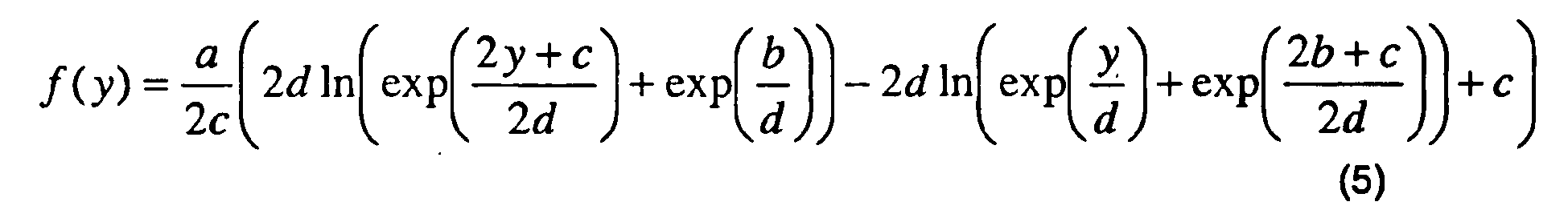
- e) Logistische Dosis-Response Funktion mit Transformationskoeffizienten a, b, c

- f) Log-Normal-Kumulative Funktion mit Transformationskoeffizienten a, b, c :

- a) Double asymptote with transformation coefficients a, b, c, m, d:
- b) sigmoid
- c) Gaussian cumulative with transformation coefficients a, b, c:
- d) Lorentz's cumulative with transformation coefficients a, b, c:
- d) Cumulative SDS function with transformation coefficients a, b, c, d:
- e) Logistic dose-response function with transformation coefficients a, b, c
- f) Log normal cumulative function with transformation coefficients a, b, c:
Die obigen Funktionen b) bis g) sind beispielsweise in der Sammlung im User's Manual zu "TableCurve2D", Version 4 Documentation, Copyright 1996 AISN Software Inc., näher beschrieben. Ebenfalls sind dort weitere geeignete Funktionen mit den oben beschriebenen Eigenschaften beschrieben.The above functions b) to g) are described in more detail in the user's manual for "TableCurve2D",
Die Parameter der Funktion ƒ(y) können beispielsweise gezielt derart ausgewählt werden, daß die Funktion ƒ(y) bestimmte Eigenschaften erfüllt. Alternativ können die Parameterwerte direkt vorgegeben werden.For example, the parameters of the function ƒ ( y ) can be selectively selected such that the function ƒ ( y ) fulfills certain properties. Alternatively, the parameter values can be specified directly.
Vorzugsweise wird gefordert, daß die y-Koordinaten yF und yN der neuen Fern- und Nahbezugspunkte in Bezug auf die alten y -Koordinaten y'F und y'N liegen. Dies bedeutet: 
![]()
wobei:
- yF
- die vertikale Position des Fernbezugspunkts des individuellen Brillenglasde- signs;
- yFD
- die vertikale Position des Fernbezugspunkts des Startdesigns;
- yN
- die vertikale Position des Nahbezugspunkts des individuellen Brillenglasde- signs;
- yND
- die vertikale Position des Nahbezugspunkts des Startdesigns
in which:
- y F
- the vertical position of the distance reference point of the individual spectacle lens design;
- y FD
- the vertical position of the distance reference point of the startup design;
- y N
- the vertical position of the near reference point of the individual spectacle lens design;
- y nd
- the vertical position of the near reference point of the startup design
Die Transformationskoeffizienten der Funktion ƒ(y) werden vorzugsweise mittels eines iterativen Verfahrens ausgehend von vorgegebenen Startwerten bestimmt.The transformation coefficients of the function ƒ (y) are preferably determined by means of an iterative method on the basis of predetermined starting values.
Vorzugsweise werden die Transformationskoeffizienten der Funktion ƒ(y) in Abhängigkeit von:
- der Differenz yF - yFD der vertikalen Position yF des Fernbezugspunkts des individuellen Brillenglasdesigns und der vertikalen Position yFD des Fernbezugspunkts des Startdesigns; und/oder
- der Differenz yN - yND der vertikalen Position yN des Nahbezugspunkts des individuellen Brillenglasdesigns und der Position yND des Nahbezugspunkts des Startdesigns
- the difference y F - y FD of the vertical position y F of the distance reference point of the individual lens design and the vertical position y FD of the distance reference point of the start design; and or
- the difference y N -y ND of the vertical position y N of the near reference point of the individual lens design and the position y ND of the near reference point of the start-up design
Beispielsweise können die Transformationskoeffizienten der Doppelasymptote 
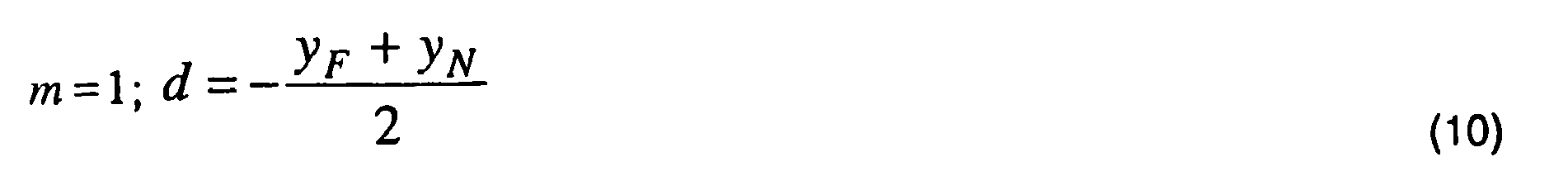


![]()
wobei:
- lD = yFD - yND
- die Progressionslänge des Startdesigns;
- l = yF - yN
- die Progressionslänge des individuellen Brillenglasdesigns;
- yF
- die vertikale Position des Fernbezugspunkts des individuellen Brillenglasde- signs;
- yFD
- die vertikale Position des Fernbezugspunkts des Startdesigns;
- yN
- die vertikale Position des Nahbezugspunkts des individuellen Brillenglasde- signs;
- yND
- die vertikale Position des Nahbezugspunkts des Nahbezugspunkts des Start- designs;
- 1+ε
- Faktor, welcher bestimmt, um wieviel der Abstand a zwischen der Fern- und Nahteilasymptote der Funktion ƒ(y) die Änderung der Progressionslänge überragt, wobei vorzugsweise ε = 0.01
in which:
- I D = y FD - y ND
- the progression length of the startup design;
- l = y F - y N
- the progression length of the individual spectacle lens design;
- y F
- the vertical position of the distance reference point of the individual spectacle lens design;
- y FD
- the vertical position of the distance reference point of the startup design;
- y N
- the vertical position of the near reference point of the individual spectacle lens design;
- y nd
- the vertical position of the near reference point of the near reference point of the startup design;
- 1 + ε
- Factor which determines by how much the distance a between the far-end and near-part asymptote of the function ƒ ( y ) exceeds the change of the progression length, wherein preferably ε = 0.01
Vorzugsweise ist die zumindest eine optische Eigenschaft des Brillenglases der Astigmatismus oder die astigmatische Abweichung.Preferably, the at least one optical property of the spectacle lens is Astigmatism or the astigmatic deviation.
Die astigmatische Abweichung wird als die Differenz zwischen dem Astigmatismus des Brillenglases (als Flächenwert oder vorzugsweise als Gebrauchswert) und dem zu korrigierenden Astigmatismus des Auges des Brillenträgers definiert.The astigmatic deviation is defined as the difference between the astigmatism of the spectacle lens (as an area value or preferably as a use value) and the astigmatism of the eye of the spectacle wearer to be corrected.
Ferner kann das individuelle Brillenglasdesign eine individuelle Objektabstandsfunktion entlang der Hauptblicklinie des Brillenglases und das Startdesign eine Startobjektabstandsfunktion entlang der Hauptlinie des Brillenglases umfassen. Die individuelle Objektabstandsfunktion wird vorzugsweise mittels einer zweiten Transformation Y 2 der Startobjektabstandsfunktion erhalten. Transformation Y und die zweite Transformation können Y 2 gleich sein.Furthermore, the individual spectacle lens design may include an individual object distance function along the main line of sight of the spectacle lens and the start design a start object distance function along the main line of the spectacle lens. The individual object distance function is preferably obtained by means of a second transformation Y 2 of the start object distance function. Transformation Y and the second transformation may be equal to Y 2 .
Die Transformation Y und die zweite Transformation Y 2 können jedoch auch unterschiedlich sein. Vorzugsweise werden die Transformationskoeffizienten der zweiten Transformation Y 2 mittels einer Newtoniteration derart bestimmt, daß der Brechwert des Brillenglases in dem Fern- und/oder dem Nahbezugspunkt des individuellen Brillenglasdesigns mit dem Brechwert des Brillenglases in dem Fern- und/oder dem Nahbezugspunkt des Startdesigns übereinstimmt.However, the transformation Y and the second transformation Y 2 may also be different. Preferably, the transformation coefficients of the second transformation Y 2 are determined by means of a Newtoniteration such that the refractive power of the spectacle lens in the far and / or near reference point of the individual spectacle lens design coincides with the refractive power of the spectacle lens in the far and / or near reference point of the starting design.
Die Objektabstandsfunktion bzw. die reziproke Objektentfernung S 1 (u 0, y) wird vorzugsweise durch eine Doppelasymtotenfunktion: 
mit Koeffizienten as,bs,cs,ds,ms beschrieben, wobei für vorgegebene Koeffizienten as,bs,ms die Koeffizienten cs ,ds mittels einer Newtoniteration bestimmt werden.The object distance function or the reciprocal object distance S 1 ( u 0 , y ) is preferably given by a double asymptotic function:
with coefficients a s , b s , c s, d s , m s , where for given coefficients a s , b s , m s the coefficients c s , d s are determined by means of a Newtoniteration.
Ferner kann das individuelle Brillenglasdesign individuelle Sollvorgaben für die entsprechenden räumlichen Verteilungen mehrerer optischer Eigenschaften des Brillenglases umfassen, wobei vorzugsweise alle individuellen Sollvorgaben mittels der Transformation Y der entsprechenden Sollvorgaben des Startdesigns berechnet werdenFurthermore, the individual spectacle lens design can individual target specifications for the corresponding spatial distributions of a plurality of optical properties of the spectacle lens in which preferably all individual target specifications are calculated by means of the transformation Y of the corresponding target specifications of the start design
Ferner bevorzugt werden die Sollvorgabe bzw. die Sollvorgaben des individuellen Brillenglasdesigns mit einem Skalierungsfaktor l/lD, einer Funktion h = h(S'(y'),lD /l) oder einer Funktion h = h(lD /l) multipliziert bzw. skaliert werden, wobei l die Progressionslänge des individuellen Brillenglasdesign und lD die Progressionslänge des Startdesigns bezeichnen.Further, the desired specification or the target specifications of the individual spectacle lens design are preferred with a scaling factor l / l D , a function h = h ( S ' ( y' ) , l D / l ) or a function h = h (l D / l ) are multiplied or scaled, where l denotes the progression length of the individual spectacle lens design and l D the progression length of the starting design.
Vorzugsweise ist h(lD /l) = a · (lD /l) + b, wobei a,b Konstanten sind.Preferably, h ( I D / I ) = a * ( I D / I ) + b , where a, b are constants.
Ferner wird gemäß der Erfindung ein computerimplementiertes Verfahren zum Berechnen eines individuellen Brillenglasdesigns für ein progressives Brillenglas mit einer variabel einstellbaren, individuellen vertikalen Position des Fern- und/oder Nahbezugspunkts vorgeschlagen, wobei das Verfahren folgende Schritte umfaßt:
- Vorgeben eines Startdesign, welches eine vorgegebene vertikale Position des Fern- und/oder des Nahbezugspunkts aufweist;
- Berechnen des individuellen Brillenglasdesigns derart, daß dieses die geforderte, individuelle vertikale Position des Fern- und/oder Nahbezugspunkts aufweist, wobei die Berechnung des individuellen Brillenglasdesigns eine Berechnung einer individuellen Objektabstandsfunktion S1 (y) entlang der Hauptlinie des Brillenglases mittels einer Zuordnung S 1(y) = S 1'(y') und einer Transformation Y : y↦y',y↦y'(y)=y-Δy(y) einer entsprechenden Objektabstandsfunktion S 1'(y') des Startdesigns umfaßt, wobei y' die vertikale Koordinate entlang der Hauptlinie des Brillenglases und y die vertikale Koordinate entlang der Hauptlinie des Brillenglases der transformierten Objektabstandsfunktion des individuellen Brillenglasdesigns bezeichnen.
- Specifying a startup design having a predetermined vertical position of the far and / or near reference points;
- Calculating the individual spectacle lens design such that it has the required, individual vertical position of the distance and / or the near reference point, the calculation of the individual spectacle lens design calculating a individual object distance function S 1 ( y ) along the main line of the spectacle lens by means of an association S 1 (FIG. y ) = S 1 '( y ') and a transformation Y: y ↦ y ', y ↦ y' ( y ) = y- Δ y ( y ) of a corresponding object distance function S 1 '( y ') of the start design, wherein y 'denotes the vertical coordinate along the main line of the spectacle lens and y the vertical coordinate along the main line of the spectacle lens of the transformed object distance function of the individual spectacle lens design.
Erfindungsgemäß wird ferner ein Verfahren zum Herstellen eines individuellen progressiven Brillenglases mit einer variabel einstellbaren vertikalen Position des Fern- und/oder Nahbezugspunkts vorgeschlagen, wobei das Verfahren folgende Schritte umfaßt:
- Berechnen eines individuellen Brillenglasdesigns, welches die geforderte vertikale Position des Fern- und/oder des Nahbezugspunkts aufweist nach einem bevorzugen erfindungsgemäßen Verfahren zum Berechnen eines individuellen Brillenglasdesigns;
- Berechnen bzw. Optimieren des Brillenglases nach dem individuellen Brillenglasdesign.
- Calculating an individual spectacle lens design having the required vertical position of the distance and / or the near reference point according to a preferred method of calculating an individual spectacle lens design according to the invention;
- Calculate or optimize the spectacle lens according to the individual spectacle lens design.
Um progressive Brillengläser mit unterschiedlichen Designs (d.h. mit unterschiedlichen Sollvorgaben für die Abbildungsfehler, insbesondere für die astigmatische Abweichung) zu erzeugen, müssen die entsprechenden unterschiedlichen Design- bzw. Sollvorgaben erzeugt und damit die Optimierungen durchgeführt werden. Eine designbasierte Optimierung eines progressiven Brillenglases kann durch Minimierung einer Zielfunktion der Form 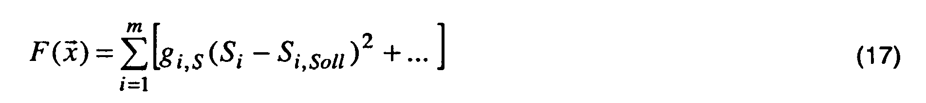
erfolgen, wobei:
- Si,Soll
- die lokale Sollvorgabe für die räumliche Verteilung zumindest einer op- tischen Eigenschaft an der i - ten Bewertungsstelle;
- Si
- die tatsächliche lokale optische Eigenschaft an der i - ten Bewertungs- stelle;
- g i,S
- die lokale Gewichtung
take place, whereby:
- S i, Soll
- the local reference setting for the spatial distribution of at least one operating tables property at the i - th evaluation point;
- S i
- the actual local optical property at the i - th evaluation site;
- g i, p
- the local weighting
Vorzugsweise erfolgt die Optimierung des progressiven Brillenglases durch Minimierung einer Zielfunktion der Form: 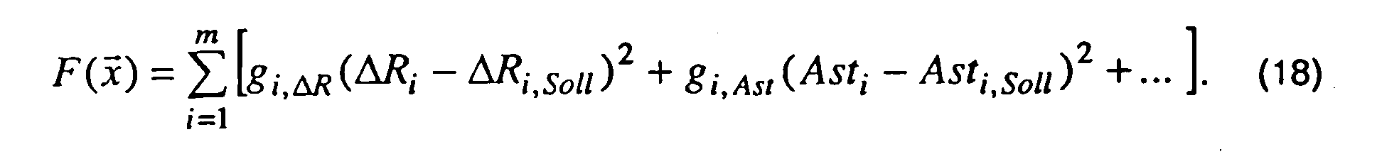
In der obigen Formel bezeichnen
- ΔRi,Soll
- den Sollwert des lokalen Refraktionsfehlers an der i -ten Bewertungs- stelle;
- ΔRi
- den tatsächlichen lokalen Refraktionsfehler an der i -ten Bewertungs- stelle;
- Asti,soll
- den Sollwert der lokalen astigmatischen Abweichung bzw. des lokalen astigmatischen Fehlers an der i - ten Bewertungsstelle;
- Asti
- die tatsächliche lokale astigmatische Abweichung an der i - ten Bewer- tungsstelle;
- gi,ΔR
- die lokale Gewichtung des Refraktionsfehlers an der i - ten Bewer- tungsstelle;
- gi,Ast
- die lokale Gewichtung der astigmatischen Abweichung an der i - ten Bewertungsstelle.
- Δ R i, target
- the set point of the local refractive error at the i- th evaluation point;
- ΔR i
- the actual local refractive error at the i- th evaluation point;
- Branch i, shall
- the setpoint of the local astigmatic deviation or the local astigmatic error at the i - th evaluation point;
- Branch i
- the actual local astigmatic deviation at the i - th rating body;
- g i, ΔR
- the weighting of the local refractive error at the i - th valuation site;
- g i, branch
- the local weighting of the astigmatic deviation at the i - th evaluation point.
Vorzugsweise erfolgt die Berechnung bzw. Optimierung des Brillenglases ferner unter Berücksichtigung von individuellen Daten des Brillenträgers.Furthermore, the calculation or optimization of the spectacle lens is preferably carried out taking into account individual data of the spectacle wearer.
Ferner umfaßt das Herstellungsverfahren:
- Bereitstellen von Flächendaten des berechneten bzw. optimierten Brillenglases; und
- Fertigen des Brillenglases gemäß den bereitgestellten Flächendaten des Brillenglases.
- Providing area data of the calculated or optimized spectacle lens; and
- Finishing the spectacle lens according to the provided surface data of the spectacle lens.
Die Fertigung bzw. Bearbeitung kann mittels numerisch gesteuerten CNC Maschinen; mittels eines Gießverfahrens, eine Kombination der beiden Verfahren oder nach einem anderen geeigneten Verfahren erfolgen.The manufacturing or machining can be done by numerically controlled CNC machines; by a casting process, a combination of the two processes, or any other suitable process.
Ferner wird gemäß der Erfindung eine Vorrichtung zum Herstellen eines individuellen progressiven Brillenglases mit einer variabel einstellbaren vertikalen Position des Fern- und/oder Nahbezugspunkts vorgeschlagen, umfassend:
- Designberechnungsmittel, welche ausgelegt sind, ein bevorzugtes erfindungsgemäßer Verfahren zum Berechnen eines individuelles Brillenglasdesigns durchzuführen;
- Optimierungs- bzw. Berechnungsmittel, welche ausgelegt sind, ein Berechnen bzw. Optimieren des Brillenglases nach dem individuellen Brillenglasdesign durchzuführen.
- Design calculation means configured to perform a preferred method of calculating an individual spectacle lens design according to the invention;
- Optimizing or calculating means, which are designed to perform a calculation or optimization of the spectacle lens according to the individual spectacle lens design.
Insbesondere umfassen die Designberechnungsmittel:
- Startdesingvorgabemittel zum Vorgeben eines Startdesigns, welches eine (individuelle) vorgegebene vertikale Position des Fern- und/oder des Nahbezugspunkts aufweist;
- Berechnungs- und Optimierungsmittel zum Berechnen des individuellen Brillenglasdesigns derart, daß dieses die geforderte, individuelle vertikale Position des Fern- und/oder Nahbezugspunkts aufweist, wobei die Berechnung des individuellen Brillenglasdesigns eine Berechnung einer Sollvorgabe S(y) für die räumliche Verteilung mindestens einer optischen Eigenschaft des individuellen Brillenglases mittels einer Zuordnung SSoll (y)=S'Soll (y') und einer Transformation Y: y↦y',y ↦ y'(y) =y-Δy(y) einer entsprechenden Sollvorgabe S'Soll (y') des Startdesigns umfaßt, wobei y' die vertikale Koordinate der Sollvorgabe des Startdesigns und y die vertikale Koordinate der transformierten Sollvorgabe des individuellen Brillenglasdesigns bezeichnen.
- Start-setting means for specifying a start-up design having an (individual) predetermined vertical position of the far and / or near reference points;
- Calculating and optimizing means for calculating the individual spectacle lens design such that it has the required individual vertical position of the distance and / or the near reference point, the calculation of the individual spectacle lens design calculating a target specification S (y) for the spatial distribution of at least one optical property the individual spectacle lens S set by means of an assignment (y) = S 'target (y') and a transformation of Y: y ↦y ', y ↦ y' (y) = y, Δ y (y) of a corresponding target value S 'target ( y ' ) of the start design, where y ' denotes the vertical coordinate of the target specification of the start design and y the vertical coordinate of the transformed target specification of the individual spectacle lens design.
Vorzugsweise umfassen die Startdesignvorgabemittel Speichermittel zum Speichern des Startdesigns sowie Mittel zum Auslesen des gespeicherten Startdesigns.Preferably, the starting design specification means comprise storage means for storing the start-up design and means for reading out the stored start-up design.
Ferner umfaßt die Vorrichtung zum Herstellen eines individuellen Brillenglases mit einer variabel einstellbaren vertikalen Position des Fern- und/oder Nahbezugspunkts vorzugsweise Bearbeitungsmittel zum Fertigbearbeiten des Brillenglases. Die Bearbeitungsmittel können z.B. CNC-Maschinen zur Direktbearbeitung eines Blanks nach den individuellen Optimierungsvorgaben umfassen.Furthermore, the device comprises for producing an individual spectacle lens with a variably adjustable vertical position of the distance and / or the near reference point preferably processing means for finishing the spectacle lens. The processing means may include, for example, CNC machines for direct processing of a blank according to the individual optimization specifications.
Vorzugsweise umfaßt die Vorrichtung zum Herstellen eines individuellen progressiven Brillenglases ferner Erfassungsmittel zum Erfassen von individuellen Daten des Brillenträgers, welche insbesondere Daten bezüglich der individuell für den Brillenträger erforderlichen dioptrischen Wirkung des Brillenglases beinhalten.Preferably, the device for producing an individual progressive spectacle lens further comprises detection means for acquiring individual data of the spectacle wearer, which in particular include data relating to the dioptric power of the spectacle lens required individually for the spectacle wearer.
Vorzugsweise weist das fertig bearbeitete Brillenglas eine einfache sphärische oder rotationssymmetrisch asphärische Fläche und eine individuell nach den erfindungsgemäß berechneten individuellen Designvorgaben sowie individuellen Parametern des Brillenträgers optimierte progressive Fläche auf. Vorzugsweise ist die sphärische oder rotationssymmetrisch asphärische Fläche die Vorderfläche (d.h. die objektseitige Fläche) des Brillenglases. Selbstverständlich ist es jedoch möglich die individuell optimierte Fläche auf der Vorderfläche des Brillenglases anzuordnen. Ebenfalls ist es möglich, daß beide Flächen des Brillenglases progressive Flächen sind.The finished spectacle lens preferably has a simple spherical or rotationally symmetrical aspherical surface and a progressive surface optimized individually according to the individual design specifications calculated according to the invention and individual parameters of the spectacle wearer. Preferably, the spherical or rotationally symmetric aspherical surface is the front surface (i.e., the object side surface) of the spectacle lens. Of course, it is possible to arrange the individually optimized surface on the front surface of the spectacle lens. It is also possible that both surfaces of the spectacle lens are progressive surfaces.
Gemäß der Erfindung wird ferner ein Computerprogrammerzeugnis sowie ein Speichermedium mit darauf gespeichertem Computerprogramm vorgeschlagen, wobei das Computerprogramm ausgelegt ist, wenn geladen und ausgeführt auf einem Computer, ein Verfahren zum Berechnen und Optimieren eines Brillenglases durchzuführen, wobei das Verfahren folgende Schritte umfaßt:
- Berechnen eines individuellen Brillenglasdesigns, welches die geforderte vertikale Position des Fern- und/oder Nahbezugspunkts aufweist, nach einem bevorzugtem erfindungsgemäßen Verfahren zum Berechnen eines individuellen Brillenglasdesigns;
- Berechnen bzw. Optimieren des Brillenglases nach dem individuellen Brillenglasdesign.
- Calculating an individual spectacle lens design having the required vertical position of the distance and / or the near reference point, according to a preferred method according to the invention for calculating an individual spectacle lens design;
- Calculate or optimize the spectacle lens according to the individual spectacle lens design.
Ferner wird eine Verwendung eines nach einem bevorzugten Herstellungsverfahren hergestellten Brillenglases in einer vorgegebenen durchschnittlichen oder individuellen Gebrauchsstellung des Brillenglases vor den Augen eines bestimmten Brillenträgers zur Korrektur einer Fehlsichtigkeit des Brillenträgers vorgeschlagen.Furthermore, a use of a spectacle lens produced according to a preferred manufacturing method in a given average or individual Proposed use position of the lens in front of the eyes of a particular wearer for the correction of ametropia of the wearer.
Vorteile der erfindungsgemäßen Verfahren bzw. Vorrichtungen sind insbesondere, daß
- die Differenz yF - yFD bzw. yN - YND beliebig vorgegeben werden kann. Dementsprechend kann eine beliebige vertikale Positionierung berücksichtigt werden;
- über die Variable Y-Transformation die bestehenden Optimierungsvorgaben bzw. die bestehende Designs beliebig gestreckt und gestaucht und somit an die individuelle Gebrauchssituation angepaßt werden können;
- keine Interpolation des Sollvorgaben von verschiedenen Designs (z.B.
verschiedenen Startdesigns, welche unterschiedliche Progressionslänge aufweisen) notwendig ist; - aus einem vorhandenen Start- bzw. Grunddesign Varianten mit unterschiedlichen (längerer oder kürzerer) Progressionszone bzw. Progressionslänge schnell und effizient erzeugt werden können;
- wenn die Objektabstandfläche automatisch angepaßt wird, es möglich ist, eine automatische Anpassung des Sollbrechwertverlaufs vorzunehmen.
- the difference y F - y FD or y N - Y ND can be arbitrarily specified. Accordingly, any vertical positioning can be considered;
- using the variable Y transformation, the existing optimization specifications or the existing designs can be stretched and compressed as desired and thus adapted to the individual situation of use;
- no interpolation of the target specifications of different designs (eg
different start designs, which have different progression lengths) is necessary; - Variants with different (longer or shorter) progression zones or progression lengths can be generated quickly and efficiently from an existing start or basic design;
- if the object distance surface is automatically adjusted, it is possible to perform an automatic adjustment of Sollbrechwertverlaufs.
Bevorzugte Ausführungsformen der Erfindung werden nachfolgend unter Bezugnahme auf die Figuren beispielhaft beschreiben.
Es zeigen:
- Fig. 1
- zwei Funktionen ƒ(y) gemäß einer bevorzugten Ausführungsform, wobei
Fig.1a ) eine Stauchung undFig.1b ) eine Streckung repräsentiert; - Fig. 2
- Beispiel für eine Stauchungstransformation;
- Fig. 3
- einen beispielhaften Verlauf der Hauptlinie eines progressiven Brillengla- ses;
- Fig. 4
- ein beispielhaftes Startdesign;
- Fig. 5
- ein beispielhaftes individuelles Brillenglasdesign;
- Fig. 6
- eine beispielhafte Eingabe- bzw. Benutzeroberfläche zur Eingabe bzw. Vorgabe von gewünschten Randbedingungen und/oder Transformationen und/oder Positionen von Bezugspunkten;
- Fig.7
- eine schematische Darstellung eines progressiven Brillenglases in Ge- brauchsstellung;
Fig. 7a eines konventionellen progressiven Brilellenglases;
Fig. 7b eines gemäß einem bevorzugten Verfahren berechneten bzw. optimierten Brillenglases; - Fig. 8a
- Brechwertisolinien eines Startdesigns;
- Fig. 8b
- Brechwertisolinien eines daraus abgeleiteten individuellen Designs;
- Fig. 9a
- Isoastigmatismuslininien des in
Fig. 8a gezeigten Grunddesigns; - Fig. 9b
- Isoastigmatismuslininien des in
Fig. 8b gezeigten individuellen Designs.
Show it:
- Fig. 1
- two functions ƒ ( y ) according to a preferred embodiment, wherein
1a ) a compression and1b shows ) represents a stretch; - Fig. 2
- Example of a compression transformation;
- Fig. 3
- an exemplary course of the main line of a progressive spectacle lens;
- Fig. 4
- an exemplary startup design;
- Fig. 5
- an exemplary individual spectacle lens design;
- Fig. 6
- an exemplary input or user interface for input or specification of desired boundary conditions and / or transformations and / or positions of reference points;
- Figure 7
- a schematic representation of a progressive spectacle lens in the use position;
Fig. 7a of a conventional progressive Brilellenglases;
FIG. 7b shows a spectacle lens calculated or optimized according to a preferred method; FIG. - Fig. 8a
- Refractive power lines of a startup design;
- Fig. 8b
- Refractive index lines of an individual design derived therefrom;
- Fig. 9a
- Isoastigmatismuslininien of in
Fig. 8a shown basic designs; - Fig. 9b
- Isoastigmatismuslininien of in
Fig. 8b shown individual designs.
Die vorliegende Erfindung bietet die Möglichkeit zum einen in technologisch einfacher und damit kostengünstiger Weise zum anderen in sehr kurzer Zeit ein individuelles Brillenglasdesign, insbesondere für ein progressives Brillenglas zu bestimmen bzw. bereitzustellen. Insbesondere kann damit ein Design für ein progressives Brillenglas mit variabel einstellbarer, individueller vertikaler Position eines Fern- und/oder Nahbezugspunkts bereitgestellt werden. Dabei werden insbesondere aus nur einem vorgegebenen Brillenglasdesign Varianten längerer und kürzerer Progression erzeugt werden und diese können zudem beliebig in vertikaler Richtung positioniert werden, ohne dass die Designcharakteristik und die guten Abbildungseigenschaften des Grunddesigns verloren gehen.The present invention offers the possibility of determining or providing an individual spectacle lens design, in particular for a progressive spectacle lens, in a technologically simple and hence cost-effective manner, on the other hand, in a very short time. In particular, a design for a progressive spectacle lens having a variably adjustable, individual vertical position of a distance and / or near reference point can thus be provided. In this case, variants of a relatively long and shorter progression are generated, in particular, from just one prespecified spectacle lens design and, moreover, these can be arbitrarily positioned in the vertical direction without losing the design characteristic and the good imaging properties of the basic design.
Nachdem eine optimale, individuelle Position des Fern- und/oder Nahbezugspunkts ermittelt wurde, wird ein individuelles Design ermittelt, welches die individuell ermittelten Fern- und Nahbezugspunkte aufweist. Die Positionen der individuell ermittelten Fern- und/oder Nahbezugspunkte gehen dabei als Designparameter bei der Berechnung und Optimierung des individuellen Brillenglasdesigns ein. Die individuell festlegbaren Fern- und Nahbezugspunkte werden daher auch nachfolgend jeweils als Designpunkt "Ferne" bzw. Designpunkt "Nähe" oder auch als Ferndesignpunkt bzw. Nahdesignpunkt bezeichnet.After an optimal, individual position of the far and / or near reference point has been determined, an individual design is determined, which has the individually determined distance and near reference points. The positions of the individually determined distance and / or near reference points are used as design parameters in the calculation and optimization of the individual spectacle lens design. The individually definable distance and near reference points are therefore also referred to hereinafter as the design point "distance" or design point "proximity" or as remote design point or near design point.
Vorzugsweise werden Sollvorgaben für ein Brillenglasdesign aus bereits hinterlegten bzw. vorhandenen Sollvorgaben transformiert, d.h. die neuen Sollvorgaben an der Stelle y gehen aus den alten Sollvorgaben an der Stelle y' hervor, wobei insbesondere y'= y - Δy(y) ist.Preferably, target values are transformed for a spectacle lens design from already deposited or existing target values, ie the new target values go at y from the old target values at y 'highlighted, in particular, y' = y - Δ y (y).
In einer bevorzugten Ausführungsform wird Δy(y) = y0 verwendet. Weicht z.B. nur die Hauptblickrichtung eines Brillenträgers bei seiner Haupttätigkeit in der Ferne in vertikaler Richtung vom Fernbezugspunkt des Glas ab, dann kann das Brillenglasdesign der Anwendung des Brillenglasträgers näher kommen, wenn die vertikale Positionierung der Sollvorgaben variabel ist bzw. angepasst werden kann, d.h. Δy(y) = y 0 ist, wobei y 0 eine Konstante ist. Ein positiver Wert von y0 bedeutet vorzugsweise, dass die neuen Sollvorgaben im Vergleich zu den alten Referenzvorgaben nach oben versetzt erscheinen.In a preferred embodiment, Δy (y) = y 0 is used. Differs for example, only the main line of sight of a spectacle wearer with his main activity in the distance in the vertical direction from the distance reference point of the glass off, then the spectacle lens design of the application of the spectacle lens wearer can get closer when the vertical positioning of the target values is variable and can be adjusted, ie, Δ y ( y ) = y 0 , where y 0 is a constant. A positive value of y 0 preferably means that the new target specifications appear offset upwards compared to the old reference specifications.
In einer weiteren bevorzugten Ausführungsform wird Δy(y) = αy + y 0 verwendet. Dies ist besonders dann vorteilhaft, wenn außer der vertikalen Positionierung die Sollvorgaben vertikal gestreckt oder gestaucht werden sollen. Insbesondere kann mit einer Konstante α > 0 das Design gestreckt und mitα < 0 gestaucht werden.In another preferred embodiment, Δ y (y) = α y + y 0 is used. This is particularly advantageous if, in addition to the vertical positioning, the target specifications are to be stretched or compressed vertically. In particular, with a constant α> 0, the design can be stretched and compressed with α <0.
In einer weiteren bevorzugten Ausführungsform wird Δy(y) = ƒ(y) + y 0 verwendet. Insbesondere steht dabei ein positiver Wert der Ableitung f'(y) für ein lokale Strekkung, ein negativer Wert für eine lokale Stauchung. Vorzugsweise ist ƒ(y) monoton, und ebenso ist vorzugsweise |ƒ'(y)| in der Progressionszone höher als im Nah- oder Fernteil bzw. Nah- oder Fernbereich, damit diese stärker vom Strecken oder Stauchen betroffen ist.In another preferred embodiment, Δ y (y) = ƒ (y) + y 0 is used. In particular, a positive value of the derivative f '(y) stands for a local extent, a negative value for a local compression. Preferably, ƒ ( y ) is monotone, and also preferably | ƒ ' ( y ) | in the progression zone higher than in the near or far part or near or far, so that it is more affected by stretching or upsetting.
Im folgenden wird ein nicht beschränkendes, beispielhaftes Verfahren in bevorzugten Ausführungsformen der Erfindung beschrieben.A non-limiting example method in preferred embodiments of the invention will now be described.
Dabei wird in einer ersten bevorzugten Ausführungsform des beispielhaften Verfahrens die Lage von Fern- und Nahdesignpunkt oder deren Abweichungen zu den Bezugspunkten des Grunddesigns im Brillenglas erfasst bzw. vorgegeben. Ferner umfaßt das Verfahren in dieser ersten Ausführungsform ein Bestimmen bzw. Ermitteln bzw. Berechnen einer einfachen und flexiblen Transformation für das Strecken bzw. Stauchen aus den Differenzen der Bezugspunkte bzw. Bezugspunktpositionen. Unter einem Fern- bzw. Nahdesignpunkt wird im Sinne der Beschreibung insbesondere der Fern- bzw. Nahbezugspunkt des Brillenglases bzw. Brillenglasdesigns verstanden.In this case, in a first preferred embodiment of the exemplary method, the position of distance and near design point or their deviations from the reference points of the basic design in the spectacle lens is detected or predetermined. Further, in this first embodiment, the method includes determining a simple and flexible transformation for the stretching from the differences of the reference points. In the sense of the description, a distance or near design point is understood in particular to be the distance or near reference point of the spectacle lens or spectacle lens design.
In einer zweiten bevorzugten Ausführungsform umfaßt das beispielhafte Verfahren alternativ oder zusätzlich ein Vorgeben der Transformation für das Strecken bzw. Stauchen. Damit werden dann vorzugsweise die Lage der Bezugspunkte und der Übergang explizit vorgegeben. Vorzugsweise wird dabei eine Iteration durchgeführt, um die Bezugspunkte an die gewünschten Hauptdurchblickstellen anzupassen.In a second preferred embodiment, the exemplary method alternatively or additionally includes predetermining the transformation for stretching. The position of the reference points and the transition are then preferably specified explicitly. Preferably, an iteration is carried out in order to adapt the reference points to the desired main viewing points.
Vorzugsweise umfaßt das beispielhafte Verfahren ein Anwenden der Transformation auf die Objektabstandsfunktion bei der Gebrauchstellungsberechnung. Die Koeffizienten der Objektabstandsfunktion bleiben dadurch vorzugsweise erhalten. Alternativ oder zusätzlich umfaßt das Verfahren ein vorzugsweise automatisches Anpassen (Strecken und/oder Stauchen) des reziproken Objektabstandes entlang der Hauptblicklinie S1HBL(y) z.B. mittels einer zweidimensionalen Newtoniteration.Preferably, the example method includes applying the transformation to the object distance function in the usage position calculation. The coefficients of the object distance function are thereby preferably preserved. Alternatively or additionally, the method comprises a preferably automatic adaptation (stretching and / or compression) of the reciprocal object distance along the main sighting line S 1HBL (y), for example by means of a two-dimensional Newtoniteration.
Vorzugsweise umfaßt das beispielhafte Verfahren ein Bestimmen bzw. Ermitteln bzw. Berechnen bzw. Transformieren aller Optimierungsvorgaben durch die Y-Transformation der Bewertungsstellen. Die Sollwertfunktionen (für Sollastigmatismus, Sollbrechwert, Gewichtung usw.) bleiben dabei vorzugsweise original erhalten. Vorzugsweise wird der Sollastigmatismus in geeigneter Weise, insbesondere nach dem Verhältnis l/lD skaliert, wobei lD die Progressionslänge des Startdesigns und l die Progressionslänge des individuellen Glases darstellt. Damit wird in besonders vorteilhafter Weise dem Satz von Minkwitz Rechnung getragen, gemäß dem sich bei einer Änderung der Progressionszonenlänge auch der Anstieg des Astigmatismus in horizontaler Richtung ändert. In einer bevorzugten Ausführungsform werden die Werte des Sollastigmatismus direkt umskaliert. In einer anderen bevorzugten Ausführungsform werden die Koeffizienten der astigmatismusbeschreibenden Funktionen angeglichen.Preferably, the example method comprises determining all the optimization specifications through the Y-transformation of the evaluation sites. The setpoint functions (for target astigmatism, setpoint value, weighting, etc.) preferably remain the same. Preferably, the target astigmatism is suitably scaled, in particular by the ratio l / l D , where l D is the progression length of the start design and l represents the progression length of the individual glass. Thus, the Minkwitz theorem is taken into account in a particularly advantageous manner, according to which changes in the progression zone length and the increase in astigmatism in the horizontal direction. In a preferred embodiment, the values of the target astigmatism are rescaled directly. In another preferred embodiment, the coefficients of the astigmatism-describing functions are adjusted.
Eine Optimierung des Brillenglases auf Basis des ermittelten Brillenglasdesigns kann dann mit verschiedenen, auch bereits bekannten und bewährten Softwaretool erfolgen.An optimization of the spectacle lens on the basis of the determined spectacle lens design can then take place with different, also already known and proven software tool.
Im folgenden werden weitere bevorzugte Aspekte in Bezug auf die Transformation bzw. Transformationsfunktion gemäß bevorzugter Ausführungsformen der vorliegenden Erfindung dargestellt. Vorzugsweise wird als Funktion f(y) eine Doppelasymptote nach 
verwendet. Dabei ergibt sich für eine bevorzugte Transformationsfunktion: 
used. This results in a preferred transformation function:
Dabei ist y die Koordinate im neuen Brillenglasdesign, der ein bestimmter Wert der Sollvorgaben zugeordnet werden soll, und y' ist dann das Argument, für das die unveränderte Sollvorgabenfunktion auszuwerten ist. Je größer der Betrag des Koeffizienten c, desto schneller der Übergang von der Nahteilasymptote zur Fernteilasymptote. Für m=1 ist die Funktion punktsymmetrisch zu y=-d, d.h. es gilt die Symmetrieeigenschaft ƒ(-d- y)-ƒ(-d)=-(ƒ(-d+y)-ƒ(-d)). In this case, y is the coordinate in the new spectacle lens design to which a specific value of the target specifications is to be assigned, and y 'is then the argument for which the unchanged target specification function is to be evaluated. The greater the magnitude of the coefficient c, the faster the transition from the near-part asymptote to the far-end asymptote. For m = 1 the function is point symmetric to y = -d , ie the symmetry property ƒ ( -d-y ) -ƒ ( -d ) = - ( ƒ ( -d + y ) -ƒ ( -d )) .
Wählt man c negativ, dann bedeutet:
- b = Wert für kleine y (Nahteilasymptote)
- b + a = Wert für große y (Fernteilasymptote)
- b = value for small y (near-field symptom)
- b + a = value for big y (remote part symptom)
Im oberen Teil des Brillenglases erhält man also eine konstante y -Verschiebung von a + b und im unteren Bereich ebenfalls eine konstante y -Verschiebung aber vom Wert b. Den gleichmäßigen weichen Übergang steuern die weiteren Koeffizienten c,d und m. Durch die geeignete Wahl des Koeffizienten m kann der Übergang von der Fernteil-Asymptote zur Nahteil-Asymptote vorgegeben werden. Zur Erhaltung der Designcharakteristik, speziell bei Universalgläsern, ist hier ein Wert von m ≈ 1 vorteilhaft.Thus, in the upper part of the spectacle lens one obtains a constant y- shift of a + b and in the lower part also a constant y- shift but of the value b . The uniform smooth transition is controlled by the further coefficients c, d and m. By the appropriate choice of the coefficient m , the transition from the far-field asymptote to the near-part asymptote can be specified. To maintain the design characteristics, especially for universal glasses, a value of m ≈ 1 is advantageous here.
Berechnung der Koeffizienten aus den Vorgaben.
- yF
- Designpunkt Ferne des individuellen Brillenglases
- yN
- Designpunkt Nähe des individuellen Brillenglases
- yFD
- Bezugspunkt Ferne des Startdesigns
- YND
- Bezugspunkt Nähe des Startdesigns
- lD = yFD - yND
- Progressionslänge des Startdesigns
- l = yF - yN
- Progressionslänge des individuellen Brillenglases
- y F
- Design point Distance of the individual spectacle lens
- y N
- Design point near the individual lens
- y FD
- Reference point of the startup design
- Y nd
- Reference point near the start design
- I D = y FD - y ND
- Progression length of the startup design
- l = y F - y N
- Progression length of the individual spectacle lens
Ein Beispiel für eine Streckungstransformation mit gegebenen Koeffizienten ist in
Der Koeffizient m steuert die Symmetrie, in
Für den Fall, dass eine direkte Vorgabe der Transformation erfolgt, werden die Koeffizienten a,b,c,d,m der Transformation einfach vorgegeben, und dann gemäß einer der Transformationen gemäß einer der Gleichungen (1) bis (7), insbesondere Gleichung (1) die Bezugspunkte daraus ermittelt.In the event that a direct specification of the transformation takes place, the coefficients a, b, c, d, m of the transformation are simply specified, and then according to a the transformations according to one of equations (1) to (7), in particular equation (1) determines the reference points therefrom.
Für den Fall des Vorgebens der Lage von Fern- und Nahdesignpunkt oder deren Abweichung zu den Bezugspunkten des Grunddesigns können zur Bestimmung der Transformationskoeffizienten unterschiedliche Möglichkeiten genutzt werden. Zwei bevorzugte Variante werden im folgenden kurz dargestellt:
- a) m =1,

In diesem Fall wird vorzugsweise ein Wert ε vorgegeben, der einen Faktor 1+ε bestimmt, um wieviel der Abstand a zwischen der Fern- und Nahteilasymptote die Änderung der Progressionslänge überragt (typischer Wert ist z.B. ε= 0,01). Dann werden die verbleibenden Koeffizienten vorzugsweise nach
ermittelt. - b) m und d beliebig vorgegeben.
- a) m = 1,
In this case, it is preferable to specify a value ε which determines afactor 1 + ε by how much the distance a between the far-end and near-part asymptote exceeds the change in the progression length (typical value is eg ε = 0.01). Then, the remaining coefficients preferably decrease
determined. - b) m and d are arbitrary.
In diesem Fall kann c auch vorgegeben werden, und a und b werden vorzugsweise numerisch über eine Newton-Iteration so zu bestimmen, dass mit y 0 = yF - yFD eine der Transformationen gemäß der Gleichung: 
wobei ƒ(y) eine Funktion gemäß einer der Gleichungen (1) bis (7), insbesondere Gleichung (1), für Nah- und Fernbezugspunkt erfüllt ist, also: 
where ƒ ( y ) satisfies a function according to one of the equations (1) to (7), in particular equation (1), for near and far reference point, ie:
Im folgenden wird das vorzugsweise automatisches Anpassen (Strecken und/oder Stauchen) des reziproken Objektabstandes entlang der Hauptblicklinie S1HBL(y) = S 1 (x = x 0(y), y) gemäß bevorzugter Ausführungsformen der Erfindung näher erläutert. Insbesondere gilt hierbei vorzugsweise S 1(x=x0 (y),y)=S1 (u 0,y), wobei x 0(y) die horizontale Koordinate eines Punktes auf der Hauptlinie bezeichnet.In the following, the preferably automatic adaptation (stretching and / or compression) of the reciprocal object distance along the main line of sight S 1HBL (y) = S 1 ( x = x 0 ( y ), y ) according to preferred embodiments of the invention is explained in more detail. In particular, S 1 ( x = x 0 ( y ), y ) = S 1 ( u 0 , y ), where x 0 ( y ) denotes the horizontal coordinate of a point on the main line, is particularly preferred here.
Grundlage bilden vorzugsweise folgende Gauss'sche Abbildungsgleichungen: 
Beim Blick vom Fernteil des Brillenglas entlang der Hauptblicklinie in den Nahteil gilt dann näherungsweise für jeden Punkt: 
mit
- F
- Brechwert des Brillenglases
- S 1
- reziproke Objektentfernung
- S'1
- reziproke bildseitige Schnittweite, ist im Normalfall = 0 bzw. - Akk(y) (Akkommodation des Auges).
With
- F
- Refractive index of the spectacle lens
- S 1
- reciprocal object distance
- S ' 1
- reciprocal image-sided focal distance, is normally 0 or - Akk ( y ) (accommodation of the eye).
Damit nun auch der Brechwertverlauf im Brillenglas entsprechend der oben beschriebenen Steckung oder Stauchung vorzugsweise automatisch während der Glasoptimierung an die neue Lage der Bezugspunkte im Brillenglas angepasst wird, wird vorzugsweise zusätzlich noch die Funktion S1 (u0, y) entsprechend abgeändert.So that now the refractive index profile in the spectacle lens according to the above-described insertion or compression is preferably adjusted automatically during glass optimization to the new position of the reference points in the spectacle lens, the function S 1 ( u 0 , y ) is preferably additionally modified accordingly.
Vorzugsweise wird S 1(u0,y) nicht frei vorgegeben, sondern mittels einer geeigneten Funktion, um die Designcharakteristik beizubehalten. Es ist vorteilhaft, die reziproke Objektentfernung beim Ausgangsglas (Designvorgabe) ebenfalls als Doppelasymptotenfunktion der Form: 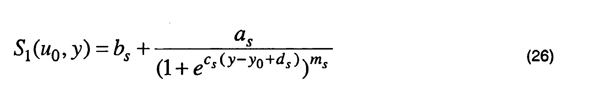
zu beschreiben und nur die Koeffizienten cs und d s über eine einfache Newtoniteration (z.B. nach dem
to describe and only the coefficients c s and d s over a simple Newtoniteration (eg after the
Dieses Vorgehen hat gegenüber der Anwendung der Transformation auf die Objektabstandsfunktion bei der Gebrauchstellungsberechnung (mit beibehaltenen Koeffizienten der Objektabstandsfunktion) den Vorteil, dass mit der abgeänderten Objektabstandsfunktion alle außerhalb des Optimierungsprogramms schon bestehenden Berechnungs- und Auswertungsprogramme, die auf die Objektabstandsfunktion zugreifen, unverändert weiter verwendet werden können (z.B. Sollwerteberechnung für die Fertigung, Soll-Ist-Vergleiche u.s.w).This procedure has the advantage over the application of the transformation to the object distance function in the calculation of usage position (with retained coefficients of the object distance function) that with the modified object distance function, all calculation and evaluation programs already existing outside the optimization program and accessing the object distance function are used unchanged can (eg setpoint calculation for production, target / actual comparisons etc).
Weitere Merkmale und Vorteile bevorzugter Ausführungsform der vorliegenden Erfindung können den weiteren beigefügten Zeichnungen entnommen werden.Further features and advantages of preferred embodiment of the present invention can be taken from the other accompanying drawings.
Dabei zeigt
astigmatisch (Cyl) = 0,0 dpt;
Achse (A) = 0°;
prismatisch (Pr) = 0 cm/m;
Basis Prisma = 0°;
Addition (Add) = 2,0 dpt.
astigmatic (Cyl) = 0.0 dpt;
Axis (A) = 0 °;
prismatic (Pr) = 0 cm / m;
Base prism = 0 °;
Addition (Add) = 2.0 dpt.
Dabei sind Isoastigmatismus-Werte für den Soll-Astigmatismus gemäß dem vorgegebenen Startdesign gezeigt.In this case, isoastigmatism values are shown for the desired astigmatism according to the given start design.
Der Fern- (BF) und der Nahbezugspunkt (BN) für dieses Design sind jeweils mit einem Kreis gekennzeichnet. Das Zeichen Bz kennzeichnet den Anpaß- bzw. Zentrierpunkt.The far (B F ) and near reference (B N ) for this design are each indicated by a circle. The character B z denotes the fitting or centering point.
In 
welche beispielhaft in
which exemplifies in
In
Vorzugsweise ist die Progressionszonenlänge zumindest in einem Bereich von 14 bis 18 mm variierbar.Preferably, the progression zone length is variable at least in a range of 14 to 18 mm.
Vorzugsweise wird ferner ein Optimierungstool zur Bestimmung bzw. Bereitstellung der Sollwerte und Modelle bereitgestellt, welche ein Überprüfungsmodul zur Prüfung der Plausibilität der Bestellparameter umfaßt.Preferably, an optimization tool for determining or providing the desired values and models is also provided, which comprises a checking module for checking the plausibility of the order parameters.
Die Eingabe- bzw. Benutzeroberfläche 10 weist einen ersten Abschnitt 12 zur Eingabe von Sollwerte der sphärischen, astigmatischen und prismatischen Wirkung des Brillenglases (Sphäre, Zylinder, Achse, Addition, Prisma horizontal, Prisma vertikal, Prisma und Basis) auf, welche z.B. mittels Refraktionsbestimmung ermittelt werden. Alle Daten beziehen sind vorzugsweise auf Daten in Gebrauchsstellung des Brillenglases.The input or
Ferner umfaßt die Eingabe- bzw. Benutzeroberfläche 10 einen Abschnitt 14 zur Eingabe von Fassungs- und Zentriervorgaben (Pupillendistanz, Hornhautscheitelabstand, Augendrehpunktabstand, Augendrehpunkt (x-, y- und z-Koordinaten), Winkel zwischen der Nullblickrichtung und der Z-Achse, Dezentration ((x-, y- und z-Koordinaten), etc.).Further, the input /
Analog zu den
Das Koordinatensystem in
Weitere Ausführungsbeispiele, Vorteile und Eigenschaften der Erfindung ergeben sich aus den beigefügten exemplarischen und nicht beschränkenden Beschreibungsseiten.The coordinate system in
Further embodiments, advantages and features of the invention will become apparent from the accompanying exemplary and non-limiting description pages.
Nachfolgend werden die individuell festlegbaren Fern- und Nahbezugspunkte jeweils als Designpunkt "Ferne" bzw. Designpunkt "Nähe" bezeichnet. Insbesondere entspricht der individuell ermittelte Fernbezugspunkt bzw. Designpunkt "Ferne" dem Punkt, durch den der Brillenglasträger beim Blick in die Ferne optimal korrigiert ist und welcher seinen persönlichen Sehgewohnheiten entspricht. Der individuell ermittelte Nahbezugpunkt bzw. Designpunkt "Nähe" entspricht dem Punkt, durch den der Brillenglasträger bei Nahsehaufgaben optimal korrigiert ist und die für ihn angenehme Blicksenkung einnehmen kann.In the following, the individually definable distance and near reference points are referred to as design point "distance" and design point "proximity", respectively. In particular, the individually determined distance reference point or design point "distance" corresponds to the point by which the spectacle lens carrier is optimally corrected when looking into the distance and which corresponds to his personal viewing habits. The individually determined near reference point or design point "proximity" corresponds to the point at which the spectacle lens carrier is optimally corrected for near vision tasks and can assume the pleasant lowering of the eye.
Es zeigen:
- Fig. 10
- Beispiel einer Maske bzw. graphischen Benutzerschnittstelle zur Eingabe von individuellen Kundenparametern;
- Fig. 11
- Beispiel einer Maske bzw. graphischen Benutzerschnittstelle zur Eingabe von Daten bezüglich der aktuellen Brille;
- Fig. 12
- Beispiel einer Maske bzw. graphischen Benutzerschnittstelle zur Eingabe von Daten bezüglich der individuellen Präferenzen bzw. Gewichtungen der Sehbereiche;
- Fig. 13
- Eine schematische Darstellung der Lage der Fern- und Nahbezugspunkte eines individuellen Brillenglasdesigns;
- Fig. 14
- Ein Beispiel unterschiedlicher Durchblickshöhen der beiden Augen;
- Fig. 15
- Eine schematische Darstellung der Hauptsehentfernung Nähe (
Fig. 15a ) und Refraktionsabstand Nähe (Fig. 15b ); - Fig. 16
- Ein Beispiel einer graphischen Benutzerschnittstelle zur Ergebnisdarstel- lung;
- Fig. 17
- Ein Beispiel einer graphischen Benutzerschnittstelle zur Ergebnisdarstel- lung und Designänderung bzw. -tuning;
- Fig. 18
- Ein Beispiel eines Bestellformulars;
- Fig. 19
- Eine schematische Darstellung des physiologischen und physikalischen Modells eines Brillenglases in einer vorgegebenen Gebrauchsstellung;
- Fig. 20 a, b
- Schematische Darstellungen der Achslagen in einem Brillenglas ohne Berücksichtigung der Listing'schen Regel (
Fig. 20a ) und mit Berücksichti- gung der Listing'schen Regel (Fig. 20b ) ; - Fig. 21 a,b
- Zwei Beispiele nicht permanenter Stempelungen individuell berechneten progressiven Brillengläsern;
- Fig. 22.
- Ein Beispiel der permanenten Gravur eines linken individuell optimierten progressiven Brillenglases;
- Fig. 23
- Ein Beispiel einer Glastüte für ein individuell optimiertes Brillenglases;
- Fig. 24
- Legende der auf der Glastüte verwendeten Piktogramme;
- Fig. 25 a,b
- Beispiele der Zentrierung eines individuellen Brillenglases (
Fig. 25a ) oder eines Standardbrillenglases (Fig. 25b ) vor den Augen des Brillenträ- gers; - Fig. 26 a-c
- Eine schematische Darstellung der Messung der Wirkungen eines indi- viduellen Brillenglases;
- Fig. 10
- Example of a mask or graphical user interface for entering individual customer parameters;
- Fig. 11
- Example of a mask or graphical user interface for entering data relating to the current glasses;
- Fig. 12
- Example of a mask or graphical user interface for inputting data with regard to the individual preferences or weightings of the viewing areas;
- Fig. 13
- A schematic representation of the location of the distance and near reference points of an individual spectacle lens design;
- Fig. 14
- An example of different heights of the two eyes;
- Fig. 15
- A schematic of the main viewing distance (
Fig. 15a ) and refraction distance near (Fig. 15b ); - Fig. 16
- An example of a graphical user interface for displaying results;
- Fig. 17
- An example of a graphical user interface for result presentation and design change or tuning;
- Fig. 18
- An example of an order form;
- Fig. 19
- A schematic representation of the physiological and physical model of a spectacle lens in a predetermined position of use;
- Fig. 20 a, b
- Schematic representations of the axial positions in a spectacle lens without consideration of Listing's rule (
Fig. 20a ) and taking into account Listing's rule (Fig. 20b ); - Fig. 21 a, b
- Two examples of non-permanent stampings of individually calculated progressive spectacle lenses;
- Fig. 22.
- An example of the permanent engraving of a left individually optimized progressive spectacle lens;
- Fig. 23
- An example of a glass bag for an individually optimized spectacle lens;
- Fig. 24
- Legend of the pictograms used on the glass bag;
- Fig. 25 a, b
- Examples of centering an individual spectacle lens (
Fig. 25a ) or a standard spectacle lens (Fig. 25b ) in front of the eyes of the spectacle wearer; - Fig. 26 ac
- A schematic representation of the measurement of the effects of an individual spectacle lens;
Konventionelle progressive Brillengläser (Gleitsichtgläser) besitzen in der Regel eine progressive Vorderfläche, während die Rezeptfläche augenseitig nach Bestelleingang gefertigt wird. Bei der Fertigung nach dem Basiskurvensystem wird auf eine begrenzte Anzahl (z.B. 72) auf Fehlsichtigkeit angepasste, vorgefertigte und damit standardisierte Gleitsichtflächen zurückgegriffen. Diese gelten allerdings nicht für jede Wirkung separat, sondern für ein bestimmtes Spektrum des Wirkungsbereichs. Die Optimierung der Gleitsichtflächen erfolgt jeweils nur für die mittlere Wirkung pro Basiskurve bzw. Wirkungsbereich. Weichen die Refraktionsdaten von den optimierten Wirkungen ab, hat dies Einschränkungen der nutzbaren Blickfelder zur Folge.Conventional progressive lenses (progressive lenses) usually have a progressive front surface, while the prescription surface is manufactured on the eye side to the order. In the base curve system fabrication, a limited number (e.g., 72) preformed and thus standardized progressive addition surfaces are used. However, these do not apply to each effect separately, but to a specific spectrum of the impact area. The optimization of the progressive power surfaces takes place only for the mean effect per base curve or area of effect. If the refraction data deviate from the optimized effects, this results in restrictions of the usable field of view.
Bereits bei kleinen Abweichungen der bestellten Wirkung in Sphäre, Zylinder, Achse oder auch Prisma und Basis von der dem Blank zugrunde liegenden Berechnung treten bei konventionellen Gleitsichtgläsern Einschränkungen in der Designtreue auf, die zu Unverträglichkeiten beim Brillenträger führen können. Hinzu kommt, dass der Optimierung konventioneller Gleitsichtgläser nur Standardwerte zugrunde liegen, die oft der Individualität der Glas-, Fassungs- und Kundendaten des Brillenträgers nicht gerecht werden.Already with small deviations of the ordered effect in sphere, cylinder, axis or prism and base of the calculation on which the blank is based, conventional progressive lenses have limitations in design fidelity, which can lead to incompatibilities with the wearer of glasses. In addition, the optimization of conventional progressive lenses is based only on standard values that often do not do justice to the individuality of the glasses, frames and customer data of the spectacle wearer.
Bei den wirkungsoptimierten Gleitsichtgläsern werden die Nachteile der konventionellen Gleitsichtgläser durch eine für jede Wirkungskombination einzeln online optimierte asphärische oder atorische Rezeptfläche beseitigt. Mit der Freiformtechnologie ist es möglich, wirkungsoptimierte Gleitsichtgläser zu fertigen. Je nach Berechnungs- und Fertigungs-Know-how können mit der Freiformtechnologie auch individuelle Gleitsichtgläser gefertigt werden.In the case of the effect-optimized progressive lenses, the disadvantages of the conventional progressive lenses are eliminated by an aspherical or atorical prescription surface optimized individually online for each combination of effects. With the free-form technology it is possible to produce effect-optimized progressive lenses. Depending on the calculation and production know-how, custom progressive lenses can also be manufactured with the free-form technology.
Es sind ebenfalls individuelle Gleitsichtgläser bekannt, welche unter Berücksichtigung der individuellen Verordnung (Sph, Zyl, Achse, Add, Prisma, Basis) und der individuellen Lage der Gläser vor dem Auge (HSA, FSW, Vorneigung, Pupillendistanz) optimiert und berechnet werden.Individual progressive lenses are also known, which are optimized and calculated taking into account the individual regulation (Sph, Zyl, axis, add, prism, base) and the individual position of the lenses in front of the eye (HSA, FSW, anterior tilt, pupillary distance).
Eine zweite Gruppe individueller Gleitsichtgläser sind Gleitsichtgläser, welche auf eine andere Art und Weise personalisiert sind, z.B. durch persönliche Verhaltensweisen des Brillenträgers oder seiner Präferenzen. Diese Gleitsichtgläser berücksichtigen jedoch nicht oder nur teilweise die individuellen Parameter. Diesen Gleitsichtgläsern liegt ein physionomisches Standardmodell zugrunde, welches mit den tatsächlichen Gegebenheiten meist nicht übereinstimmt und so optische Abweichungen und/oder Leistungsverluste nach sich zieht.A second group of individual progressive lenses are progressive lenses, which are personalized in another way, e.g. by personal behaviors of the spectacle wearer or his preferences. However, these progressive lenses do not or only partially take into account the individual parameters. These progressive lenses are based on a physionomic standard model, which usually does not agree with the actual conditions and thus causes optical deviations and / or power losses.
In allen Fällen war jedoch das Design eines progressiven Brillenglases bisher fest definiert. Mit einem bevorzugten erfindungsgemäßen Verfahren ist es möglich, das Design des Brillenglases individuell auf die Kundenbedürfnisse anzupassen, wobei individuelle Kundenparameter (z.B. Pupillendistanz (PD), Hornhautscheitelabstand (HSA), Fassungsform, Vorneigung (VN), Fassungsscheibenwinkel (FSW), individuelle Position des Fern- und/oder Nahbezugspunkte, individueller Nahabstand, etc.) berücksichtigt werden.In all cases, however, the design of a progressive spectacle lens has been firmly defined so far. With a preferred method according to the invention, it is possible to tailor the design of the spectacle lens individually to the customer's needs, with individual customer parameters (eg pupillary distance (PD), corneal vertex distance (HSA), frame shape, front inclination (VN), lens angle (FSW), individual position of the remote - and / or near reference points, individual near distance, etc.) are taken into account.
Vorzugsweise fließen die Seherfahrung und die Bedürfnisse bzw. Sehanforderungen des Kunden in einem bevorzugten erfindungsgemäßen Verfahren zum Berechnen eines individuellen Designs und zum Herstellen eines Brillenglases ein. Somit ist es möglich, unter Benutzung des fachlichen Know-how z.B. eines Augenoptikers und unter Mitwirkung des Kunden (Brillenträgers), ein individuelles progressives Brillenglas zu gestalten. Vorzugsweise werden dabei Vor- und Nachteile des Vorgängerglases berücksichtigt.Preferably, the customer's viewing experience and needs or visual requirements are incorporated in a preferred method of calculating an individualized design and producing a spectacle lens in accordance with the present invention. Thus, it is possible, using the technical know-how e.g. of an optician and with the assistance of the customer (spectacle wearer) to design an individual progressive lens. Preferably, advantages and disadvantages of the preceding glass are taken into account.
Die individuellen Parameter (z.B. Pupillendistanz PD, Hornhautscheitelabstand HSA, Vorneigung VN, Fassungsscheibenwinkel FSW, etc.), welche beispielsweise automatisch mittels einer geeigneten 3-D Meßvorrichtung, wie z.B. mittels der 3-D Videozentriervorrichtung ImpressionIST der Firma Rodenstock GmbH oder alternativ mittels herkömmlichen Meßtools ermittelt werden, werden bei der Berechnung bzw. Optimierung der räumlichen Lagen, insbesondere der vertikalen und/oder horizontalen Position des Fern- und/oder Nahbezugspunkts berücksichtigt.The individual parameters (eg pupillary distance PD, corneal vertex distance HSA, preadjustment VN, frame disc angle FSW, etc.), which for example automatically by means of a suitable 3-D measuring device, such as by means of the 3-D video centering device ImpressionIST Rodenstock GmbH or alternatively by means of conventional measuring tools are determined, are taken into account in the calculation or optimization of the spatial positions, in particular the vertical and / or horizontal position of the distance and / or the near reference point.
Die individuellen Parameter können beispielsweise in folgenden Grenzen variieren:
- Pupillendistanz (PD)
von 30 bis 80 mm - Hornhautscheitelabstand (HSA)
von 3 bis 50 mm - Vorneigung (VN) von -10 bis +20 Grad
- Fassungsscheibenwinkel (FSW) von -10 bis +35 Grad.
- Pupillary distance (PD) from 30 to 80 mm
- Corneal vertex distance (HSA) from 3 to 50 mm
- Pre-tilt (VN) from -10 to +20 degrees
- Bracket angle (FSW) from -10 to +35 degrees.
Ferner können neben den individuellen Parametern auch die speziellen Sehgewohnheiten des Brillenträgers berücksichtigt werden.Furthermore, in addition to the individual parameters and the special viewing habits of the wearer can be considered.
So können z.B. in einer ersten Maske bzw. graphischen Benutzerschnittstelle (nicht gezeigt) Informationen zu dem Kunden (z.B. Name, Kontaktadresse, Fassungswahl, etc.) eingegeben oder z.B. aus einer Datenbank übernommen werden. Die ausgewählte Fassung, welche z.B. mit Hilfe eines geeigneten Tracers (wie z.B. ImpressionIST der Firma Rodenstock) direkt vermessen oder aus einer Datenbank abgerufen werden kann, kann ebenfalls angezeigt werden.Thus, e.g. in a first mask (not shown), information about the customer (e.g., name, contact address, frame selection, etc.) is input or e.g. be taken from a database. The selected version, which e.g. can also be measured directly or retrieved from a database using a suitable tracer (such as ImpressionIST from Rodenstock).
In
Die in
- einen Abschnitt "Refraktionsdaten" (Abschnitt 122) umfassend Eingabefelder zur Eingabe von individuellen Refraktionsdaten wie Sphäre "Sph", Zylinder "Cyl", Achse, Prisma, Basis);
- einen Abschnitt "Individuelle Parameter" (Abschnitt 124) umfassend Eingabefelder zur Eingabe von individuellen Parametern der Augen des Brillenträgers und/oder der individuellen Gebrauchsstellung (Pupillendistanz "PD", Hornhautscheitelabstand "HSA", Vorneigung "VN", Fassungsscheibenwinkel "FSW");
- einen Abschnitt "Fassungs- und Zentrierdaten" (Abschnitt 126) umfassend Eingabefelder zur Eingabe von Fassungs- und Zentrierdaten (Einschleifhöhe, Scheibenlänge, Scheibenhöhe, Abstand zwischen den Gläsern "AzG" bzw. "AZG") sowie gegebenenfalls einen Anzeigeabschnitt (Abschnitt 127) zur Anzeige der Zentrierung der Brille angepasst an dem Kastenmaß.
- a section "refraction data" (section 122 ) comprising input fields for inputting individual refraction data such as sphere "Sph", cylinder "Cyl", axis, prism, base);
- a section "Individual Parameters" (section 124 ) comprising input fields for entering individual parameters of the wearer's eyes and / or the individual position of use (pupillary distance "PD", corneal vertex distance "HSA", anterior inclination "VN", socket angle "FSW");
- a section "Sizing and centering data" (clause 126 ) comprising input fields for entering sizing and centering data (grinding height, slice length, slice height, distance between the glasses "AzG" and "AZG" respectively) and optionally a display section (section 127) Display of the centering of the glasses adapted to the box size.
Die Fassungsdaten können in entsprechenden Eingabefeldern eingegeben werden. Diese Werte können automatisch eingetragen werden, wenn die Fassung z.B. mittels eines Tracers oder aus einer Liste von Fassungen ausgewählt wird. Die Zentrierdaten können gegebenenfalls direkt von einem 3-D Videozentriersystem (z.B. 3-D Videozentriersystem der Firma Rodenstock GmbG) übernommen werden. Mit einer Funktion "Anpassen an Kastenmaß" kann die Fassung den gegebenenfalls geänderten Fassungsdaten anpasst werden.The frame data can be entered in corresponding input fields. These values can be entered automatically when the socket is e.g. is selected by means of a tracer or from a list of versions. If necessary, the centering data can be taken directly from a 3-D video centering system (eg 3-D video centering system from Rodenstock GmbG). With a function "Adapt to box dimension", the version can be adapted to the possibly changed frame data.
Im Abschnitt 126 "Fassungs- und Zentrierdaten" kann eine Fassung aus einer Datenbank ausgewählt werden, z.B. falls vorher mittels eines Tracers keine Fassung aufgenommen bzw. vermessen worden ist. Insbesondere kann die Fassung aus einer Liste in einem sich öffnenden Pop-up-Fenster ausgewählt werden. Form- und Fassungsdaten werden vorzugsweise ebenfalls angezeigt. Die Auswahl kann durch Bestätigen übernommen werden. Ebenfalls kann eine genäherte Fassung aus einer Anzahl verschiedener Fassungsformen ("genäherte Formen") ausgewählt werden. Hierbei kann sich z.B. ein anderes Pop-up-Fenster öffnen, in dem die Fassung aus einer Auswahl gängiger Formen ausgewählt werden kann.In
Die in
Ebenfalls weist die graphische Benutzerschnittstelle 120 einen Abschnitt 134 "Designparameter" mit entsprechenden Eingabefelder zur Eingabe von:
- den individuellen Nahabstand bei der Refraktionsbestimmung (Refraktionsabstand Nähe);
- der Hauptsehentfernung Nähe; und
- der individuellen Zusatzwirkung
- the individual near distance in the refraction determination (refraction distance near);
- the main viewing distance proximity; and
- the individual additional effect
Wenn keine Daten bezüglich des individuellen Nahabstands eingegeben werden, wird angenommen, daß bis zur einen Addition von 2,5 dpt der individuelle Nahabstand bei der Refraktionsbestimmung 40 cm beträgt. In anderen Worten wird angenommen, daß die bestellte Addition in 40 cm bestimmt wurde und auch die Hauptsehentfernung des Brillenglasträgers in dieser Entfernung liegt. Bei höheren Additionen entspricht der Kehrwert der Addition dem maximalen Nahabstand. Wenn nur eines der beiden Eingabefelder "Refraktionsabstand Nähe" oder "Hauptsehentfernung Nähe" ausgefüllt wird, wird angenommen, daß der Wert auch für die jeweils andere Entfernung gilt. Der Inset und der Astigmatismus werden auf die Hauptsehentfernung "Nähe" berechnet.If no data on the individual near distance are input, it is assumed that, up to an addition of 2.5 dpt, the individual near distance in the refraction determination is 40 cm. In other words, it is assumed that the ordered addition was determined in 40 cm and also the main viewing distance of the spectacle lens wearer is at this distance. For higher additions, the inverse of the addition corresponds to the maximum near distance. If only one of the two input fields "Refraction distance near" or "Main distance near" is filled in, it is assumed that the value also applies to the other distance. The inset and the astigmatism are calculated to the main viewing distance "proximity".
Wenn für den Refraktionsabstand "Nähe" und für die Hauptsehentfernung "Nähe" jeweils unterschiedliche Werte in dem entsprechenden Eingabefeld eingetragen werden, wird automatisch auch die individuelle Zusatzwirkung für die Hauptsehentfernung berechnet. Die individuelle Zusatzwirkung wird angezeigt, wenn sie außerhalb des Lieferbereichs liegt (0,75 dpt bis 3,50 dpt) oder mehr als 0,5 dpt von der Bestelladdition abweicht.If different values are entered in the corresponding input field for the refraction distance "Proximity" and for the main viewing distance "Proximity", the individual additional effect for the main viewing distance is automatically calculated as well. The individual additional effect is displayed if it is outside the delivery range (0.75 D to 3.50 D) or more than 0.5 D deviates from the order addition.
Bestellte Addition (Refraktion) = 2.00 dpt, Hauptsehentfernung Nähe = 30 cm, Refraktionsabstand in der Nähe = 40 cm. Die bestellte Addition von 2.00 dpt wird für 30 cm optimiert und es erfolgt eine Anpassung der Addition. Neben dem Inset wird auch der Astigmatismus schiefer Bündel für die gewünschte Hauptsehentfernung korrigiert.Ordered addition (refraction) = 2.00 dpt, main distance near = 30 cm, refraction distance nearby = 40 cm. The ordered addition of 2.00 D is optimized for 30 cm and the addition is adjusted. In addition to the inset, the astigmatism slanting bundles is also corrected for the desired main visual distance.
Wenn nur ein Abstand (Hauptsehentfernung oder Refraktionsabstand) angegeben wird, wird davon ausgegangen, daß sich die bestellte Addition auf den angegebenen Abstand bezieht. Hier erfolgt keine Anpassung der Addition, und das Brillenglasdesign bzw. das Brillenglas wird für die bestellte Addition im angegebenen Nahabstand berechnet bzw. optimiert. Wird kein Nahabstand (Hauptsehentfernung und/oder Refraktionsabstand) angegeben, wird davon ausgegangen, daß in 40 cm refraktioniert worden ist und dieser Refraktionsabstand der Hauptsehentfernung in der Nähe entspricht. Hier erfolgt keine Anpassung der Addition und das individuelle Brillenglasdesign bzw. das individuelle Brillenglas wird für die bestellte Addition für 40 cm berechnet bzw. optimiert. In der Regel liegen die von Herstellern lieferbaren Additionen in einem Bereich zwischen 0,75 dpt bis 3,50 dpt. Anhand der folgenden einfachen Rechnung kann der Optiker bzw. Optometrist überprüfen, ob das Brillenglas lieferbar ist: 
wobei:
- IZ
- die individuelle Zusatzwirkung in dpt;
- Add
- die Addition in dpt;
- RDN
- den Betrag des Refraktionsabstands Nähe in Meter; und
- MVDN
- den Betrag der Hauptsehentfernung Nähe
in which:
- IZ
- the individual additional effect in dpt;
- Add
- the addition in dpt;
- RDN
- the amount of refraction distance nearness in meters; and
- mvdn
- the amount of the main viewing distance close
- Addition Refraktion = 1,75 dpt;Addition refraction = 1.75 D;
- Refraktionsabstand Nähe = 40 cm;Refraction distance near = 40 cm;
- Hauptsehentfernung Nähe = 30 cm;Main viewing distance near = 30 cm;
- IZ = 1,75 dpt - 2,50 dpt + 3,33 dpt = 2,58 dpt. IZ = 1.75 D - 2.50 D + 3.33 D = 2.58 D.
- Addition Refraktion = 2,00 dpt;Addition refraction = 2.00 dpt;
- Refraktionsabstand Nähe = 40 cm;Refraction distance near = 40 cm;
- Hauptsehentfernung Nähe = 20 cm;Main viewing distance near = 20 cm;
- IZ = 2.00 dpt - 2.50 dpt + 5.00 dpt = 4,50 dpt IZ = 2.00 D - 2.50 D + 5.00 D = 4.50 D
In der Rechnung wird davon ausgegangen, daß sich keine Änderung des Akkommodationserfolgs aufgrund der Veränderung des Nahabstands ergibt. Dies stellt jedoch lediglich eine Näherung dar.The calculation assumes that there is no change in the accommodation result due to the change in the near distance. However, this is only an approximation.
Die in
In diese Maske können Angaben zum Vorgängerglas gemacht werden, falls dieses bekannt ist. So kann aus einer Liste 142 ("Glastyp") ausgewählt werden, ob der Kunde zuvor ein Einstärken-, Mehrstärken- oder Gleitsichtglas getragen hat oder ob es sich um die erste Brille des Kunden handelt (keine Vorgängerbrille). Wurde ein Gleitsichtglas getragen, können zum Beispiel nähere Angaben zum Material, zum Brechungsindex und/oder zur Progressionslänge z.B. in einem Pop-up-Menü gemacht werden. Die Progressionslänge des Vorgängerglases kann ferner automatisch anhand der Wahl des Vorgängerprodukts oder manuell eingegeben werden. Insbesondere kann die Progressionslänge des Vorgängerglases grob z.B. als eine "Standard" bzw. lange Progression oder als eine kurze ("XS") Progressionslänge eingestuft werden.In this mask information can be made to the previous glass, if this is known. Thus, it can be selected from a list 142 ("glass type") whether the customer has previously worn a single, multi-level or progressive lens or whether it is the first pair of glasses of the customer (no previous goggles). If a progressive lens was worn, for example, details on the material, the refractive index and / or the progression length can be made in a pop-up menu, for example. The progression length of the precursor glass can also be entered automatically based on the choice of the predecessor product or manually. In particular, the progression length of the precursor glass can roughly be classified, for example, as a "standard" or long progression or as a short ("XS") progression length.
Wenn die Addition des Vorgängerglases bekannt ist, kann diese in einem dafür vorgesehenen Eingabefeld 144 "Addition des Vorgängerglases" eintragen werden. So kann die Addition des Vorgängerglases mit der neuen Addition verglichen werden. Bei einer Additionserhöhung von mehr als 0,5 dpt kann ein Hinweisfeld (z.B. als Pop-up-Fenster) erscheinen, das auf die Besonderheiten der Additionserhöhung hinweist.If the addition of the preceding glass is known, it can be entered in a designated
Jeweils fünf verschiedene Piktogramme für die Ferne, die mittlere Entfernung und die Nähe sowie für das Aktivverhalten des Brillenträgers symbolisieren die Bereiche, die der Brillenträger bei der Wahl seines Designprofils gegeneinander abwägen soll. Die Piktogramme dienen als Beispiele für den jeweiligen Entfernungsbereich und stellen nur eine kleine Auswahl aller möglichen Tätigkeiten für diese Entfernung dar. Mit den zu vergebenden Punkten können die Bereiche gewichtet werden.Five different pictograms for the distance, the middle distance and the proximity as well as for the active behavior of the spectacle wearer symbolize the areas that the spectacle wearer should balance when choosing his design profile. The pictograms serve as examples of the distance range and represent only a small selection of all possible activities for this distance. With the points to be awarded the areas can be weighted.
In einem konkreten Beispiel können insgesamt 9 Punkte auf die vier verschiedenen Bereiche (Ferne, mittlere Entfernung, Nähe und Aktivverhalten) verteilt werden. Je wichtiger dem Kunden der jeweilige Entfernungsbereich ist bzw. je mehr seiner Tätigkeiten in einen Bereich fallen, desto mehr Punkte für diesen Bereich werden vergeben. Die Anzahl der Punkte pro Bereich sowie die Gesamtpunktzahl können beschränkt werden. So können z.B. pro Bereich maximal 5 Punkte vergeben werden, insgesamt jedoch nicht mehr als 9 Punkte.In a concrete example, a total of 9 points can be distributed over the four different areas (distance, average distance, proximity and active behavior). The more important the customer the distance range is or the more of his activities fall into an area, the more points awarded for this area. The number of points per area and the total score can be limited. For example, a maximum of 5 points can be awarded per area, but no more than 9 points in total.
Die vergebenen Punkte bestimmen das individuelle Designprofil des Brillenträgers. Vereinfacht gilt: Je mehr Punkte für die Ferne in Relation zur gegebenen Gesamtpunktzahl vergeben werden, desto tiefer liegt der individuelle Fernbezugspunkt und je mehr Punkte für die Nähe in Relation zur gegebenen Gesamtpunktzahl vergeben werden, desto höher liegt der individuelle Nahbezugspunkt. Die Punkte für das Aktivverhalten und das Sehen in mittleren Entfernungen wirken sich in erster Linie auf die Länge der Progressionszone aus und bestimmen somit auch wie verzeichnungsfrei das Brillenglas ist. Bei der Vergabe der Punkte entspricht eine gleich große Punktzahl in jedem Bereich einem ausgewogenen, universellen Design.The points awarded determine the individual design profile of the spectacle wearer. Simplified, the more points awarded to the distance in relation to the given total score, the lower the individual distance reference point, and the more points awarded for proximity in relation to the given total score, the higher the individual's near reference point. The points for the active behavior and the vision in medium distances affect first and foremost on the length of the progression zone and thus also determine how distortion-free the spectacle lens is. When awarding the points, an equal number of points in each area corresponds to a balanced, universal design.
Die vertikale Höhe des Fernbezugspunkts kann vorzugsweise in einem Bereich von +4 bis -4 mm gegenüber dem für dieses Brillenglas vom Hersteller festgelegten Zentrier- bzw. Anpaßpunkt in Abhängigkeit von den individuellen Daten des Brillenträgers flexibel bestimmt werden. Der Nahbezugspunkt kann vorzugsweise flexibel zwischen 13 und 20 mm vertikal unterhalb des Zentrier- bzw. Anpaßpunkts festgelegt werden. Daraus ergibt sich eine flexibel wählbare Progressionslänge, welche vorzugsweise minimal 13 mm und maximal 24 mm betragen kann. Vorzugsweise können der Fern- und Nahbezugspunkt in Stufen von 0,1 mm innerhalb eines zulässigen Bereichs frei festgelegt werden. Wird z.B. der Fernbezugspunkt bzw. auf -4 mm vertikale Höhe verschoben, so muss der Nahbezugspunkt mindestens auf einer vertikalen Höhe von -17 mm liegen. Wird der Fernbezugspunkt +4 mm verschoben, so ergibt sich eine Mindestprogressionslänge von 17 mm, da der Nahbezugspunkt vorzugsweise nicht weiter als -13 mm verschoben wird.The vertical height of the distance reference point may preferably be flexibly determined in a range of +4 to -4 mm relative to the centering or fitting point specified by the manufacturer for this spectacle lens, depending on the individual data of the spectacle wearer. The near reference point may preferably be set flexibly between 13 and 20 mm vertically below the centering point. This results in a flexibly selectable progression length, which can preferably be at least 13 mm and a maximum of 24 mm. Preferably, the far and near reference points can be freely set in steps of 0.1 mm within an allowable range. For example, if the remote reference point or -4 mm vertical Height shifted, the near reference point must be at least at a vertical height of -17 mm. If the distance reference point is shifted by +4 mm, the result is a minimum progression length of 17 mm, since the near reference point is preferably displaced no further than -13 mm.
Dabei beträgt vorzugsweise der minimale vertikale Abstand vom unteren Fassungsrand zum Nahbezugspunkt 2 mm. Der Fernbezugspunkt weist vorzugsweise minimal einen vertikalen Abstand von 6 mm, vorzugsweise 8 mm von dem oberen Fassungsrand auf. Mit den minimal zulässigen Abständen des Fern- und Nahbezugspunkts von dem oberen bzw. dem unteren Fassungsrand läßt sich die maximal zulässige Progressionslänge berechnen. Die Progressionslänge wird hierbei als der vertikale Abstand zwischen dem Fern- und dem Nahbezugspunkt definiert.In this case, the minimum vertical distance from the lower edge of the frame to the near reference point is preferably 2 mm. The distance reference point preferably has a minimum of a vertical distance of 6 mm, preferably 8 mm from the upper edge of the frame. With the minimum allowable distances of the far and near reference points from the upper and lower frame margins, the maximum allowable progression length can be calculated. The progression length is defined here as the vertical distance between the far and near reference points.
Aus der folgenden Tabelle kann entnommen werden, was durch Verschieben der Designpunkte im Gleitsichtglas beispielsweise erreicht werden kann:
Tabelle:
Table:
Die Positionen der Fern- und Nahbezugspunkte sind vorzugsweise gleich für das rechte und das linke Brillenglas. Bei unterschiedlicher Durchblickshöhe können sich dadurch jedoch Nachteile in den Sehbereichen für eines der beiden Augen ergeben. Damit die Sehbereiche für beide Augen voll genutzt werden können, ist es vorteilhaft den jeweils kleineren vertikalen Abstand des Nahbezugspunktes vom Zentrierpunkt auszuwählen bzw. festzulegen.The positions of the distance and near reference points are preferably the same for the right and left lenses. In the case of different viewing heights, however, this can result in disadvantages in the viewing areas for one of the two eyes. So that the viewing areas can be fully utilized for both eyes, it is advantageous to select or set the respectively smaller vertical distance of the near reference point from the centering point.
- F1L,R
- den vertikalen Abstand "Zentrierpunkt- oberer Fassungsrand" des linken (L) bzw. des rechten (R) Brillenglases; und
- F2L,R
- den vertikalen Abstand "unterer Zentrierpunkt - unterer Fassungsrand" des linken (L) bzw. des rechten (R) Brillenglases.
- F1 L, R
- the vertical distance "center point upper edge of the frame" of the left (L) and the right (R) spectacle lens; and
- F2 L, R
- the vertical distance "lower center point - lower edge of the frame" of the left (L) and the right (R) spectacle lens.
In
Die Angaben zu den Objektentfernungen "Ferne" und "Nähe" bei der Refraktionsbestimmung werden bei der Berechnung und Optimierung berücksichtigt. Somit kann der Strahlengang, welcher der tatsächlichen Gebrauchssituation entspricht, genauer simuliert werden und folglich die Abbildungsqualität verbessert werden.The information on the object distances "distance" and "proximity" in the refraction determination are taken into account in the calculation and optimization. Thus, the beam path corresponding to the actual use situation can be more accurately simulated, and consequently the imaging quality can be improved.
Insbesondere ist es so möglich, die Hauptsehentfernung beim Blick in die Nähe in der tatsächlichen Gebrauchsstellung des Brillenglases bei der Glasberechnung zu berücksichtigen.
Generell wird davon ausgegangen, daß die Addition in einem Refraktionsabstand in der Nähe von 40 cm bestimmt wurde (gilt bis Addition 2,50 dpt, für höhere Additionen gilt 1/Addition) und diese einer Hauptsehentfernung in der Nähe von 40 cm entspricht. Weicht die Hauptsehentfernung in der Nähe vom Refraktionsabstand in der Nähe ab, kann das individuelle Brillenglasdesign auf diese Hauptsehentfernung optimiert werden.In general, it is assumed that the addition was determined at a refraction distance near 40 cm (applies to addition 2.50 D, for
Wenn die optimale individuelle Position des Fern- und/oder Nahbezugspunkts anhand von individuellen Daten des Brillenträgers ermittelt wird, wird ein entsprechendes Brillenglasdesign mit den so ermittelten Positionen des Fern- und Nahbezugspunkts und gegebenenfalls unter Berücksichtigung weiterer individueller Parameter des Brillenträgers automatisch berechnet.When the optimum individual position of the distance and / or the near reference point is determined on the basis of individual data of the spectacle wearer, a corresponding spectacle lens design is automatically calculated with the thus determined positions of the distance and near reference point and optionally taking into account further individual parameters of the spectacle wearer.
Der Designvorschlag kann mittels einer geeigneten graphischen Benutzerschnittstellen 160A zur Ergebnisdarstellung (Designempfehlung) - wie in
Die graphischen Benutzerschnittstellen 160A und 160B sind in zwei Bereiche aufgeteilt: im oberen Bereich 162 werden Informationen zum Thema "Sehen" und/oder "Performance" mit dem vorgeschlagenen Design für ein individuelles Brillenglas; im unteren Bereich 164 Informationen zum Thema "Aussehen" bzw. "Geometrie" des individuellen Brillenglases bzw. Brille dargestellt.The
Im Bereich "Aussehen" 164 können insbesondere kosmetische Eigenschaften bzw. Daten bezüglich der Ästhetik des Brillenglases (z.B. Gewicht, geometrische Daten wie Bauhöhe, maximale Randdicke, Mittendicke, Basiskurve, etc.) des gerandeten Brillenglases bzw. der gerandeten Brillengläser visualisiert bzw. graphisch dargestellt werden. Die Visualisierung der kosmetischen Eigenschaften des Brillenglases kann beispielsweise mittels einer dreidimensionalen graphischen Darstellung eines Models des Brillenglases 166 mit den ermittelten geometrischen Daten erfolgen, wie z.B. in
Der Bereich "Aussehen" 164 kann ferner einen Subbereich 168 umfassen, in welchem numerische Werte bezüglich der geometrischen Eigenschaften des Brillenglases, wie z.B. Bauhöhe, maximale Randdicke, Mittendicke, Gewicht, Basiskurve des gerandeten Glases, etc. gezeigt werden. Diese Werte können Näherungswerte sein, welche gegebenenfalls von den tatsächlichen Glasgeometriedaten abweichen. Zusätzlich können neben den Gravuren auch die individuell ermittelten Fern- und Nahbezugspunkte als Stempelpunkte gezeigt werden.The "appearance"
Mittels geeigneter Buttons können Ansichten 169 der gerandeten Brillengläser aus verschiedenen statischen Perspektiven gezeigt werden (Fassung von oben, Fassung von vorn, von der Seite, von schräg oben). Ebenfalls können z.B. mittels Betätigung eines Animationsbutton die gerandeten Brillengläser in der gewählten Ansicht dynamisch rotierend dargestellt werden. Zur besseren Detailansicht kann das Bild z.B. über einen entsprechenden Button vergrößert dargestellt werden.By means of suitable buttons, views 169 of the edged spectacle lenses can be shown from different static perspectives (version from above, version from the front, from the side, obliquely from above). Also, for example, by pressing an animation button, the gerandeten eyeglass lenses in the selected view are displayed dynamically rotating. For a better detailed view, the picture can be enlarged, eg via a corresponding button.
Der Bereich "Aussehen" 164 umfaßt ferner einen Abschnitt 170 zur Anzeige von numerischen Werten bezüglich des Brechungsindexes und einen Abschnitt zur Anzeige der Basiskurve (Abschnitt 172). Die angezeigten Werte für die Basiskurve und den Brechungsindex setzen sich aus dem Wirkungsbereich, dem notwendigen Durchmesser, den Basiskurvenwunsch und den Refraktionsdaten zusammen. Daher sind Abweichungen zu dem der Maske "Bestellwerte" eingegebenen Basiskurvenwunsch möglich. Über entsprechende Auswahlfelder können die technisch realisierbaren Werte für Basiskurve und Brechungsindex des Glases verändert werden. Falls Änderungen der Basiskurven-Vorgabe, der Brechungsindex, etc. vorgenommen werden, können z.B. durch Betätigen eines Buttons "Aktualisieren" die Grafik und die Geometriedaten entsprechend den geänderten Werten neu berechnet werden.The "appearance"
Neben der Visualisierung der kosmetischen Eigenschaften des Brillenglases erfolgt ferner eine Visualisierung der optischen Eigenschaften des Brillenglases (Sehbereiche, insbesondere räumliche Lage und Größe der einzelnen Sehbereiche). Die Darstellung der Sehbereichsgrößen kann lediglich relativ zu den Verordnungsdaten erfolgen, ohne daß eine eventuelle Materialabhängigkeit berücksichtigt wird. Selbstverständlich kann jedoch eine Berücksichtigung einer Materialabhängigkeit vorgesehen werden. Neben einer Visualisierung des "Aussehens" erfolgt eine Visualisierung des "Sehens" durch das Brillenglas. Insbesondere kann eine Visualisierung des Sehkomforts (z.B. Blicksenkung, Schaukeln, peripheres Sehen, Verzerrungen, etc.) vorgesehen werden.In addition to the visualization of the cosmetic properties of the spectacle lens, there is also a visualization of the optical properties of the spectacle lens (viewing areas, in particular spatial position and size of the individual viewing areas). The representation of the Sehbereichsgrößen can only be done relative to the ordinance data, without any material dependence is taken into account. Of course, however, a consideration of a material dependence can be provided. In addition to a visualization of the "appearance" is a visualization of the "seeing" through the lens. In particular, visualization of visual comfort (e.g., eye-tilt, swings, peripheral vision, distortions, etc.) may be provided.
Zusätzlich kann eine geeignete Darstellung von Performancewerten bezüglich der Sehbereiche, des Sehkomforts und/oder der kosmetischen Eigenschaften bzw. der Ästhetik des individuellen Brillenglases vorgesehen werden. Ebenfalls können Performancewerte alternativer Designvorschläge dargestellt werden.In addition, a suitable representation of performance values with regard to the visual areas, the visual comfort and / or the cosmetic properties or the aesthetics of the individual spectacle lens can be provided. Also, performance values of alternative design proposals can be displayed.
Der Bereich "Sehen" 162 der graphischen Benutzerschnittstellen 160A und 160B ist daher grundsätzlich in mehrere Unter- bzw. Subbereiche gegliedert.The area "see" 162 of the
In dem Subbereich 174 "Binokulare Sehbereichsdarstellung" des Bereichs 162 wird z.B. das für den Kunden und die angegebene Fassung ideale Design anhand einer Ellipse schematisch gezeigt. Graue Bereiche sind dabei mit Abbildungsfehlern (z.B. Astigmatismus in Gebrauchsstellung größer als 0,5 dpt) behaftete Bereiche. Zusätzlich kann gegebenenfalls der Verlauf der 0,5 dpt Isoastigmatismuslinie gezeigt werden. Die vertikalen Höhen der Fern- und Nahbezugspunkte können jeweils durch (gegebenenfalls unterschiedlich gefärbte) Linien 175, 176 gekennzeichnet werden. Im Subbereich 177 des Bereichs 162 werden numerische Werte für die räumliche Lage (insbesondere für die vertikale Höhe im Bezug auf den Zentrierpunkt) des Fern- und des Nahbezugspunkts gezeigt.In the sub-area 174 "Binocular View Area Representation" of the
Im Subbereich 178 "Designprofil" des Bereichs 162 wird ein qualitativer Vergleich der Sehbereichsgrößen zueinander, z.B. in Form von unterschiedlich längen Balken dargestellt, wobei F den Fernbereich, Z den Zwischenbereich und N den Nahbereich bezeichnet. Die Länge des jeweiligen Balkens bzw. Schiebers korreliert mit der jeweiligen Schwerpunktsetzung, die einem entsprechenden Entfernungsbereich zugeordnet ist. Da sich die Länge im Designprofil aus den Angaben aller vorheriger Masken ergibt, können sie gegebenenfalls von den zuvor ermittelten Präferenzen bzw. Gewichtungen des Kunden abweichen. Darüber hinaus kann eine qualitative Bewertung des dynamischen Seheindrucks durch das individuelle Brillenglas dargestellt werden. Je höher der Balken, welcher den dynamischen Seheindruck (Balken "Dynamik") darstellt, desto länger wird die Progressionszonenlänge und desto einstärkenähnlicher wird das Brillenglas bzw. desto weniger Schaukeleffekt weist das Brillenglas auf.In the sub-area 178 "Design Profile" of the
Zusätzlich kann dem Augenoptiker/Optometristen und/oder dem Brillenträger die Möglichkeit gegeben werden das so berechnete individuelle Brillenglasdesign aktiv zu verändern. Die Veränderung erfolgt beispielsweise in dem die räumliche Position, insbesondere die vertikale Höhe des Fern- und/oder Nahbezugspunkts, aktiv verändert wird. Alternativ können die Gewichtungen der Sehbereiche verändert werden.In addition, the optician / optometrist and / or the spectacle wearer can be given the opportunity to actively change the thus calculated individual spectacle lens design. The change takes place, for example, in that the spatial position, in particular the vertical height of the distance and / or the near reference point, is actively changed. Alternatively, the weights of the viewing areas can be changed.
Die Änderung bzw. die Anpassung der Position des Fern- und/oder Nahbezugspunkts und/oder der Präferenzen bezüglich der Sehbereiche kann beispielsweise mittels einer geeigneten graphischen Benutzerschnittstelle erfolgen. Ein Beispiel einer geeigneten graphischen Benutzerschnittstelle in Form von Schieberegler 180 ist in
Das neue Brillenglasdesign mit der geänderten Position des Fern- und/oder Nahbezugspunkts wird vorzugsweise in Echtzeit berechnet und visualisiert. Vorzugsweise wird ebenfalls die Differenz bzw. die Veränderung der optischen Eigenschaften des neuen gegenüber dem alten Brillenglasdesign visualisiert.The new spectacle lens design with the changed position of the distance and / or the near reference point is preferably calculated and visualized in real time. Preferably, the difference or the change in the optical properties of the new compared to the old spectacle lens design is also visualized.
So kann z.B. in dem Designtuner über die in der Designempfehlung (
Zusätzlich zu den flächig grau dargestellten Sehbereichen aus der Designempfehlung können vorzugsweise farbliche (z.B. gelbe) Sehbereichslinien (z.B. 0,5 dpt Isoastigmatismuslinie) erscheinen, welche das abgeänderte, individuelle Design zeigen. Ebenfalls ändern sich im Subbereich Designprofil (178) das Verhältnis der Größe der Sehbereiche zueinander sowie die Länge des Balkens "Dynamik". Die vergebenen Punkte im Abschnitt "Designprofiler" werden vorzugsweise durch die Veränderungen im Abschnitt "Designtuner" nicht beeinflusst.In addition to the areas of gray shown in the design recommendation, color (eg yellow) visual range lines (eg 0.5 dpt I soastigmatism line) may appear which show the modified, individual design. Likewise, in the Design Profile sub-area ( 178 ), the ratio of the size of the viewing areas to each other and the length of the "Dynamics" bar change. The awarded points in the section "Designprofiler" are preferably not influenced by the changes in the section "Designtuner".
Die nachfolgend aufgeführten Beispiele zeigen individuelle progressive Designs mit individuell, in Abhängigkeit von den erfaßten individuellen Daten des Brillenträgers ermittelten Fern- und Nahbezugspunkte.The examples below show individual progressive designs with individual distance and near reference points determined as a function of the individual wearer's acquired individual data.
Der Brillenglasträger legt großen Wert auf einen breiten Zwischenbereich und wünscht sich ein "eher ruhiges" Brillenglas mit wenigen Schaukelbewegungen, da er aus beruflichen Gründen den überwiegenden Teil des Tages im Zwischenbereich (mittlere Entfernungen) sehen muss. In seiner jetzigen Brille trägt er ein Gleitsichtglas mit einer Progressionszonenlänge von 18 mm.The eyeglass wearer attaches great importance to a wide intermediate area and wants a "rather quiet" lens with a few rocking movements, as he has to see for professional reasons, the majority of the day in the intermediate range (medium distances). In his present glasses he wears a progressive lens with a progression zone length of 18 mm.
Für diesen Brillenglasträger empfiehlt das Programm für die ausgewählte Fassung und entsprechende Zentrierung den Fernbezugspunkt auf +2,4 mm über das Zentrier- bzw. Anpaßpunkt zu setzen. Der Nahbezugspunkt würde optimal bei -19 mm unterhalb des Zentrier- bzw. Anpaßpunkt liegen. Mit diesem progressiven Brillenglas hat der Architekt einen guten Kompromiß aus entspannter Kopfhaltung, einem breitem Zwischenbereich und geringen Schaukelbewegungen für seine Sehgewohnheiten.For this lens carrier, the program recommends setting the distance reference point to +2.4 mm above the centering or fitting point for the selected frame and corresponding centering. The near reference point would be optimally at -19 mm below the centering or fitting point. With this progressive lens, the architect has a good compromise of relaxed head posture, a wide intermediate range and low rocking movements for his viewing habits.
Sie legt großen Wert auf einen großen Nahbereich und wünscht sich eine geringere Blicksenkung als bei ihrem jetzigen Gleitsichtglas, da sie aus beruflichen Gründen den überwiegenden Teil des Tages mit Arbeiten in der Nähe verbringt. In der jetzigen Brille trägt sie ein Gleitsichtglas mit einer Progressionszonenlänge von 18 mm. Für diese Kundin empfiehlt das Programm für die ausgewählte Fassung und entsprechende Zentrierung den Fernbezugspunkt auf 1,5 mm über das Zentrier- bzw. Anpaßpunkt zu verlegen. Der Nahbezugspunkt würde optimal bei -15,5 mm unterhalb des Zentrier- bzw. Anpaßpunkts liegen. Damit hat die Lektorin einen guten Kompromiss aus breiterem Nahbereich und entspannter Kopfhaltung.She places great value on a large close-up area and desires a lower leveling than with her current progressive lens, because she spends most of the day working nearby with her for professional reasons. In the present glasses she wears a progressive lens with a progression zone length of 18 mm. For this customer, the program recommends laying the distance reference point to 1.5 mm above the centering or fitting point for the selected version and corresponding centering. The near reference point would be optimally -15.5 mm below the centering or fitting point. Thus, the editor has a good compromise from wider close range and relaxed head posture.
Wenn der Brillenglasträger großen Wert auf einen breiten Zwischen- und Nahbereich und geringe Schaukelbewegungen im Brillenglas legt, wird von dem Programm empfohlen in Abhängigkeit von den anderen Eingabeparametern den Fernbezugspunkt nach oben zu verschieben. Der Fernbezugspunkt würde sich dann oberhalb vom Zentrier- bzw. Anpaßpunkt befinden. Je nach Refraktionsdaten und individuellen Parametern kann sich in diesen Fällen eine "Nebelung" im Zentrier- bzw. Anpaßpunkt von bis zu +0,25 dpt ergeben. Neben dieser geringfügigen Nebelung im Zentrierpunkt können sich auch seitliche Einschränkungen im Fernbereich ergeben, da der Brillenglasträger - bei einer Verschiebung des Fernbezugspunkts nach oben - in Nullblickrichtung durch die bereits früher beginnende Progression im Brillenglas sieht. Durch die veränderte Lage der Progressionszone im Brillenglas können die Sehbereiche auf Höhe des Zentrierpunktes dementsprechend kleiner ausfallen, weil die peripheren Abbildungsfehler "nach oben" verschoben werden. Der Brillenglasträger erhält jedoch bei der Wahl dieser Positionierung des Fernbezugspunkts ein nach seinen individuellen Sehgewohnheiten gestaltetes bzw. optimiertes Brillenglasdesign bzw. Brillenglas.If the eyeglass wearer places great value on a wide intermediate and close range and low swinging movements in the lens, the program recommends the remote reference point depending on the other input parameters move upwards. The distance reference point would then be above the centering or fitting point. Depending on the refraction data and individual parameters, a "fogging" in the centering or fitting point of up to +0.25 D can result in these cases. In addition to this slight misting in the centering point, lateral restrictions in the far range may also arise, since the spectacle lens carrier - in the case of a shift of the distance reference point upwards - sees in zero viewing direction through the progression already beginning earlier in the spectacle lens. Due to the changed position of the progression zone in the spectacle lens, the visual areas at the level of the centering point can correspondingly be smaller because the peripheral aberrations are shifted "upwards". However, when selecting this positioning of the distance reference point, the spectacle lens carrier receives a spectacle lens design or spectacle lens designed or optimized according to its individual viewing habits.
Der Brillenglasträger legt besonderen Wert auf einen großen Fernbereich, da er aus beruflichen Gründen den überwiegenden Teil des Tages mit Sehen in die Ferne verbringt. In seiner jetzigen Brille trägt er ein Gleitsichtglas mit Progressionszonenlänge 18 mm. Das Programm berechnet automatisch und empfiehlt bei diesem Kunden für die ausgewählte Fassung und entsprechende Zentrierung den Fernbezugspunkt auf -2,5 mm unterhalb des Zentrier- bzw. Anpaßpunkts zu setzen. Der Nahbezugspunkt würde optimal bei -18,4 mm unterhalb des Zentrier- bzw. Anpaßpunkts liegen. Mit diesem Brillenglas hat der Brillenglasträger einen großen Fernbereich und einen guten Kompromiß aus geringen Schaukelbewegungen sowie gut ausnutzbarem Zwischen- und Nahbereich.The eyeglass wearer attaches particular importance to a large distance range, because he spends most of the day with vision in the distance for professional reasons. In his present glasses he wears a progressive lens with
Auf die Frage, für welche Tätigkeiten bzw. Sehanforderungen die Brillenglasträgerin ihre Brille benutzt, ergibt sich z. B. folgendes Profil:
- Sie fährt regelmäßig Auto und sieht fern;
- Sie spielt ein Instrument und geht 2x die Woche zur Orchesterprobe;
- Abends liest Sie zur Entspannung gerne die abonnierte Tageszeitung;
- Mindestens 1 x die Woche treibt sie Sport wie z. B. Joggen oder spielt Handball in ihrem Verein.
- She drives a car regularly and watches TV;
- She plays an instrument and goes to the orchestra rehearsal twice a week;
- In the evening, you can read the subscribed daily newspaper for relaxation;
- At least once a week she does sports such as B. Jogging or playing handball in their club.
In der aktuellen Brille trägt die Brillenglasträgerin Gleitsichtgläser mit normaler Progressionszonenlänge. Da keinerlei Präferenzen festzustellen sind und die Tätigkeiten dieser Kundin gleich auf die Bereiche Ferne, mittlere Entfernung und Nähe verteilt sind, werden jeweils gleich viele Punkte für alle Entfernungen und auch für das Aktivverhalten bzw. Dynamik vergeben. In anderen Worten werden alle Sehbereiche und das dynamische Verhalten bzw. die dynamischen Eigenschaften gleich gewichtet. In dem konkreten Beispiel werden für alle Bereiche des in
Auf die Frage, für welche Tätigkeiten bzw. Sehanforderungen der Brillenglasträger seine Brille benutzt, ergibt sich folgendes Profil:
- Er legt besonderen Wert auf ungestörtes Sehen in der Ferne, da er aus beruflichen Gründen den überwiegenden Teil des Tages im Auto verbringt;
- In die mittlere Entfernung schaut er nur, um das Armaturenbrett klar erkennen zu können;
- Die Nähe nutzt der Brillenglasträger nur für kurzzeitige Schreibtischtätigkeiten, wie z.B. Vertragsabschlüsse und Ähnliches;
- In seiner Freizeit spielt er gerne Tennis und Squash, dabei legt er Wert auf wenig Schaukelbewegungen im Brillenglas.
- He attaches particular importance to undisturbed seeing in the distance, as he spends most of the day in the car for professional reasons;
- In the middle distance, he only looks to clearly recognize the dashboard can;
- The proximity uses the eyeglass lens carrier only for short-term desk activities, such as contracts and the like;
- In his spare time he likes to play tennis and squash, while he attaches importance to little rocking movements in the spectacle lens.
In der aktuellen Brille trägt der Brillenglasträger Gleitsichtgläser mit normaler Progressionszonenlänge (PZL). Die Präferenz des Brillenglasträgers liegt hier eindeutig in der Ferne, die mittlere Entfernung und die Nähe spielen eine untergeordnete Rolle. Daher wurden für dieses Beispiel für die Ferne 4 Punkte, für mittlere Entfernungen und Nähe jeweils 1 Punkt vergeben (vgl.
Auf die Frage, für welche Tätigkeiten bzw. Sehanforderungen der Brillenglasträger seine Brille benutzt, ergibt sich folgendes Profil:
- Die Ferne spielt für Ihn eine untergeordnete Rolle, da er z. B. beim Autofahren die Brille meist abnimmt;
- Das Sehen in den mittleren Entfernungen ist ihm besonders wichtig;
- Der Brillenträger reagiert auf ungewohnte Verzeichnungen sehr sensibel, z. B. bei gekrümmten Linien in seinen zeichnerischen Skizzen;
- Nach getaner Arbeit liest er gern Kriminalromane;
- Aufgrund seines stressigen Jobs kommt er nicht dazu, Sport zu treiben oder sich zu bewegen.
- The distance plays a subordinate role for him, since he z. B. when driving the glasses usually decreases;
- Seeing in the middle distances is especially important to him;
- The spectacle wearer reacts to unusual distortions very sensitively, z. B. in curved lines in his drawing sketches;
- He likes to read crime novels after work is done;
- Due to his stressful job, he does not come to do sports or to move.
Die wichtigste Entfernung für diesen Brillenglasträger ist also die mittlere Entfernung, auch die Nähe ist für ihn wichtig, die Ferne und das Aktivverhalten spielen eine untergeordnete Rolle. Daher werden in dem in
Auf die Frage, für welche Tätigkeiten bzw. Sehanforderungen die Brillenglasträgerin ihre Brille benutzt, ergibt sich folgendes Profil:
- Sie benutzt die Brille kaum für Tätigkeiten in der Ferne, daher spielt diese eine untergeordnete Rolle;
- Für ihren Beruf ist das Lesen von Schriftstücken besonders wichtig;
- Sie legt großen Wert auf eine angenehme Blicksenkung für Nahsehaufgaben;
- Aufgrund der eher statischen Haltung am Arbeitsplatz spielen Schaukelbewegungen eine untergeordnete Rolle;
- In die mittlere Entfernung schaut die Kundin vor allem bei gelegentlicher Bildschirmarbeit.
- She hardly uses the glasses for remote activities, so she plays a subordinate role;
- For their profession, reading documents is particularly important;
- She attaches great importance to a pleasant eye-drop for near vision tasks;
- Due to the rather static posture at the workplace swinging movements play a minor role;
- In the middle distance, the customer looks especially at occasional screen work.
Die wichtigste Entfernung für diese Brillenglasträgerin ist also die Nähe. Auch die mittlere Entfernung ist wichtig, die Ferne sowie auch das Aktivverhalten spielen eine untergeordnete Rolle. Daher werden in dem in
Mit einem Button "Aktive Auswahl übernehmen" kann festgelegt werden, welche Daten für die Bestellung übernommen werden sollen. Es werden z.B. stets die Daten des Bereichs übernommen der gerade aktiv (nicht im Hintergrund) ist. Nach Betätigen des Buttons "Aktive Auswahl übernehmen" kann ferner ein mit dem Ergebnis gefülltes Bestellformular ausgedruckt werden. Das Bestellformular kann ferner z.B. mit weiteren Details, wie z.B. Farbe, Beschichtung, ColorMatic Farbe, Messbrille usw. ergänzt werden. Die individuellen Daten können ebenfalls gespeichert werden und/oder online an einem Brillenglashersteller übermittelt werden.With a button "Apply active selection" it can be determined which data should be transferred for the order. There are e.g. always the data of the area that is currently active (not in the background). After pressing the button "Accept active selection" an order form filled with the result can also be printed out. The order form may also be e.g. with further details, such as Color, coating, ColorMatic color, measuring glasses, etc. are added. The individual data can also be stored and / or transmitted online to a spectacle lens manufacturer.
Die individuellen Daten des Brillenträgers können ebenfalls mittels geeigneter Bestellformulare erfaßt und dem Brillenglashersteller weiter übermittelt werden.
Anschließend wird ein individuelles Brillenglas optimiert bzw. berechnet, wobei die Optimierung unter Berücksichtigung zumindest eines Teils der ermittelten individuellen Daten, insbesondere Daten bezüglich der individuellen Parameter des Brillenträgers und der individuellen Gebrauchsstellung (Fassungsscheibenwinkel, Vorneigung, Pupillendistanz, Hornhautscheitelabstand, etc,) erfolgt.Subsequently, an individual spectacle lens is optimized or calculated, the optimization taking into account at least part of the determined individual data, in particular data regarding the individual parameters of the spectacle wearer and the individual use position (lens angle, preadjustment, pupil distance, corneal vertex distance, etc.,) takes place.
Um die Abbildungseigenschaften von Brillengläsern in der Tragesituation zu beschreiben und/oder zu berechnen, sind in der geometrischen Optik zwei Berechnungsverfahren bekannt:
- Berechnung mit Lichtstrahlen (Ray Tracing); und
- Berechnung mit Wellenfronten (Wave Tracing).
- Calculation with light rays (ray tracing); and
- Calculation with wavefronts (wave tracing).
Der Begriff "Ray Tracing" setzt sich aus Ray = Strahl und Tracing = Verfolgung zusammen. In der geometrischen Optik wird das Ray Tracing Verfahren eingesetzt, um optische Abbildungen zu beschreiben. Die Berechnung eines Brillenglases mit Ray Tracing ist jedoch sehr zeitaufwändig, da für jeden Punkt im Brillenglas außer dem eigentlichen Lichtstrahl bzw. Hauptstrahl auch noch ein "begleitendes" Bündel an Nachbarstrahlen durch das Brillenglas simuliert werden muss.The term "ray tracing" is made up of ray = ray and tracing = pursuit. In geometric optics, the ray tracing method is used to describe optical images. However, the calculation of a spectacle lens with ray tracing is very time-consuming, since for each point in the spectacle lens, in addition to the actual light beam or main beam, an "accompanying" bundle of neighboring rays must also be simulated through the spectacle lens.
Vorzugsweise wird das individuelle Brillenglas mittels eines Wavefront-Tracing-Verfahrens, insbesondere mittels einer lokalen Wellenfrontoptimierung berechnet. Der Begriff "Wave Tracing" setzt sich aus Wave = Welle und Tracing = Verfolgung zusammen. Wellenfronten können genauso wie Lichtstrahlen eingesetzt werden, um optische Abbildungen zu beschreiben oder zu berechnen. Eine Wellenfront ist die Fläche gleicher Phase einer sich ausbreitenden Welle. Eine jede solche Wellenfront fasst sämtliche Eigenschaften eines Bündels aus Nachbarstrahlen in einem einzigen Objekt zusammen. Dadurch kann die Berechnungszeit deutlich reduziert werden, so daß eine individuelle Optimierung jedes einzelnen Brillenglases ermöglicht wird. Insbesondere ist es durch die freie Wahl der Designpunkte Ferne und/oder Nähe möglich, die Verteilung der Abbildungseigenschaften auf dem Brillenglas wunschgerecht an die individuellen Sehgewohnheiten des Brillenträgers anzupassen.Preferably, the individual spectacle lens is calculated by means of a wavefront tracing method, in particular by means of a local wavefront optimization. The term "wave tracing" is composed of wave = wave and tracing = pursuit. Wave fronts can be used as well as light rays to describe or calculate optical images. A wavefront is the area of equal phase of a propagating wave. Each such wavefront summarizes all the properties of a bundle of neighbor rays in a single object. As a result, the calculation time can be significantly reduced, so that an individual optimization of each individual spectacle lens is made possible. In particular, it is possible through the free choice of the design points distance and / or proximity to adapt the distribution of the imaging properties on the spectacle lens to the individual viewing habits of the spectacle wearer.
Zur Berechnung des Brillenglases wird vorzugsweise eine flexible Flächengestaltung der individuell zu berechnenden progressiven Fläche mit einer Mehrzahl an Bewertungsstellen (vorzugsweise über 7000 Bewertungsstellen) eingesetzt, wobei jeder dieser Bewertungsstellen eine eigene lokale Wellenfrontdurchrechnung zugeordnet wird. Die individuelle progressive Fläche wird vorzugsweise mittels Minimierung einer Zielfunktion, welche an den Bewertungsstellen ausgewertet wird, und unter Berücksichtigung des physiologischen Sehmodells optimiert. Auf diese Weise ist es möglich, durch individuelle Wellenfrontdurchrechnungen sehr schnell und damit online nach dem Bestelleingang die Optimierung eines Brillenglases nach der variablen Zielfunktion durchzuführen.In order to calculate the spectacle lens, it is preferable to use a flexible surface design of the individually calculable progressive surface with a plurality of evaluation sites (preferably over 7000 assessment sites), each of these evaluation sites being assigned its own local wavefront computation. The individual progressive surface is preferably determined by minimizing an objective function which is evaluated at the evaluation sites, and taking into account optimized physiological model. In this way, it is possible to carry out the optimization of a spectacle lens according to the variable objective function very quickly and thus online after the receipt of the order by means of individual wave front calculations.
Die Berechnung des Brillenglases umfaßt vorzugsweise eine Optimierung mit mehr als 2000 Optimierungsparametern in einem hochdimensionalen Raum. Für die so vorgenommene Echtzeit-Online-Optimierung können Multiprozessor-Großrechner eingesetzt werden.The calculation of the spectacle lens preferably comprises an optimization with more than 2000 optimization parameters in a high-dimensional space. Multiprocessor mainframes can be used for real-time online optimization.
Vorzugsweise werden bei der individuellen Optimierung des Brillenglases nicht nur Abbildungsfehler niedriger Ordnung (Sphäre, Zylinder, Prisma), sondern auch Abbildungsfehler höherer Ordnung (z.B. Koma und sphärische Abberation) minimiert. Diesbezüglich wird z.B. auf
Vorzugsweise wird bei der Optimierung der individuellen Brillengläser insbesondere die Listing'sche Regel berücksichtigt.Preferably, in the optimization of the individual spectacle lenses, in particular the Listing's rule is taken into account.
Da das Auge bei peripheren Blickauslenkungen eine leichte Rollbewegung ausführt, darf es keine feste Zylinderachse über das gesamte Brillenglas geben, sondern diese muss sich im Übergang von der Horizontalen zur Vertikalen leicht ändern (
- je größer der Refraktionszylinder des Kunden ist, und/oder
- je stärker die Blickauslenkung von der horizontalen und vertikalen Auslenkung abweicht, und/oder
- je stärker bzw. größer die Blickauslenkung absolut ist.
- the larger the refracting cylinder of the customer, and / or
- the more the viewing deflection deviates from the horizontal and vertical deflection, and / or
- the greater or greater the gaze deflection is absolute.
In einem konventionellen progressiven Brillenglas mit einer progressiven Vorderfläche und einer sphärische/torischen Rezeptfläche kann die Listing'sche Regel - im Gegensatz zu Brillengläsern mit einer progressiven, individuellen, augenseitigen Freiformfläche - nicht umgesetzt werden.In a conventional progressive spectacle lens with a progressive front surface and a spherical / toric prescription surface, the Listing's rule - unlike spectacle lenses with a progressive, individual, eye-shaped freeform surface - can not be implemented.
Ferner bevorzugt wird bei der Optimierung und Berechnung des individuellen progressiven Brillenglases eine individuelle Vordezentration berücksichtig. Somit werden die ausnutzbaren Durchmesser vergrößert. Die optimale Vordezentration kann anhand von Daten bezüglich der Fassungs- bzw. Brillenglasform sowie Daten bezüglich der Zentrierung automatisch berechnet werden. Alternativ kann eine individuelle Vordezentration vom Augenoptiker/Optometrist selbst festgelegt werden. In diesem Fall kann der anhand einer speziellen Zentrierkarte ermittelte gewünschte Durchmesser ebenfalls berücksichtigt werden. Insbesondere kann eine Vordezentration von bis zu 5 mm berücksichtigt werden.Furthermore, an individual predecentration is preferably taken into account in the optimization and calculation of the individual progressive spectacle lens. Thus, the exploitable diameters are increased. The optimum pre-concentration can be calculated automatically based on data regarding the frame or spectacle lens shape as well as data relating to the centering. Alternatively, an individual pre-concentration may be determined by the optometrist / optometrist himself. In this case, the desired diameter determined by means of a special centering card can also be taken into account. In particular, a pre-concentration of up to 5 mm can be taken into account.
Das individuell berechnete Brillenglas weist vorzugsweise eine sphärische oder rotationssymmetrische asphärische objektseitige Vorderfläche und eine individuelle in Abhängigkeit von den individuell festgelegten Bezugs- bzw. Designpunkte Ferne und Nähe, den individuellen Refraktionsdaten, den individuellen Parameter des Brillenträgers und der Gebrauchssituation (z.B. Pupillendistanz, Vorneigung, Fassungsscheibenwinkel, Hornhautscheitelabstand, etc.) optimierte progressive, augenseitige Freiformfläche auf.The individually calculated spectacle lens preferably has a spherical or rotationally symmetrical aspherical object-side front surface and an individual depending on the individually determined reference or design points distance and proximity, the individual refraction data, the individual parameter of the spectacle wearer and the situation of use (eg pupil distance, front inclination, frame disc angle . Corneal vertex distance, etc.) optimized progressive, eye-side freeform surface.
Die Position der individuellen Fern- und Nahbezugspunkte wird vorzugsweise mittels einer individuellen Stempelung mittels nicht permanenten Markierungen aufgezeichnet. Vorzugsweise kann die Position der individuellen Fern- und Nahbezugspunkte ferner anhand von permanenten Markierungen bzw. Mikrogravuren des Brillenglases und einer Rekonstruktionsvorschrift (Schablone, Zentrierkarte) eindeutig rekonstruiert werden.The position of the individual far and near reference points is preferably recorded by means of individual stamping by means of non-permanent markings. Preferably, the position of the individual far and near reference points can furthermore be clearly reconstructed on the basis of permanent markings or microgravures of the spectacle lens and a reconstruction rule (template, centering card).
Die nicht permanente Markierung bzw. der Stempel eines individuell nach einem bevorzugten erfindungsgemäßen Verfahren optimierten Brillenglases besteht aus "beweglichen" und "fixen" Bestandteilen. Zu den beweglichen Teilen gehören zwei runde Klammern 202, welche die Lage des Fernbezugspunkts bzw. des Designpunkts Ferne kennzeichnen, sowie der Nahmeßkreis 204, welcher die Lage des Nahbezugspunkts bzw. des Designpunkts "Nähe" markiert. Der Fernbezugspunkt befindet sich in der Mitte der runden Klammern 202 und der Nahbezugspunkt in der Mitte des Nahmeßkreises 204. Abhängig von der Lage der Fern- und Nahbezugspunkte kann der Stempel eines individuellen Brillenglases daher unterschiedlich aussehen. Mittels eines Kreuzes 206 (Zentrierkreuz) wird die Position des Zentrier- bzw. Anpaßpunkts gekennzeichnet.The non-permanent marking or the stamp of an individually optimized according to a preferred method according to the invention spectacle lens consists of "movable" and "fixed" components. The moving parts include two
Der Prismenbezugspunkt 208 befindet sich im Normalfall 4 mm unter dem Zentrierpunkt. Bei höherer Anisometropie und Kundenwunsch bezüglich einer bestimmten Gewichtung (z. B. wenn im Nahbereich die prismatischen Vertikaldifferenzen angeglichen werden sollen) kann ein Prismenangleichspunkt in die gewünschte Richtung verschoben werden.The
Bei dem in
Vorzugsweise sind die Werte für die Lage der Fern- und Nahbezugspunkte (insbesondere für die vertikale Höhe im Bezug auf den Zentrier- bzw. Anpaßpunkt) ebenfalls permanent im Brillenglas eingraviert.Preferably, the values for the position of the distance and near reference points (in particular for the vertical height with respect to the centering or fitting point) are also permanently engraved in the spectacle lens.
In Ausnahmefällen kann die Stempelung von der oben beschriebenen abweichen. Ferner kann eine explizite nicht permanente Kennzeichnung der Positionen der Fern- und Nahbezugspunkte und/oder des Zentrier- bzw. Anpaßpunkts fehlen. Die Bezugspunkte können jedoch mit Hilfe einer Rekonstruktionsvorschrift, umfassend eine Zentrierkarte, aufgestempelte Skalen in 1 mm-Schritten und eine Glastüte eindeutig, ermittelt werden. Zur Rekonstruktion der Bezugspunkte wird die Brillenfassung mit gekennzeichnetem Zentrierpunkt auf das Zentrierkreuz der Zentrierkarte gelegt und die Position der Fern- und Nahbezugspunkte auf das Brillenglas gezeichnet. Die Position der Fern- und Nahbezugspunkte kann ebenfalls mit Hilfe der permanent eingravierten Werte unterhalb der nasalen Basiskurven- und Indexgravur ermittelt werden.In exceptional cases, the stamp may differ from the one described above. Furthermore, an explicit non-permanent marking of the positions of the distance and near reference points and / or the centering or fitting point may be missing. However, the reference points can be determined unambiguously by means of a reconstruction rule comprising a centering card, stamped scales in 1 mm increments and a glass bag. To reconstruct the reference points, the spectacle frame with the marked centering point is placed on the centering cross of the centering card and the position of the distance and near reference points drawn on the spectacle lens. The position of the far and near reference points can also be determined using the permanently engraved values below the nasal base curve and index engraving.
Neben einer Rekonstruktion der Position der Bezugspunkte ist es mit einer entsprechenden Zentrierkarte möglich einen optimalen Durchmesser des rohrunden Brillenglases zu ermitteln.In addition to a reconstruction of the position of the reference points, it is possible with a corresponding Zentrierkarte to determine an optimal diameter of the tubular spectacle lens.
Die Ermittlung eines optimalen Durchmessers mittels Zentrierkarte kann folgendermaßen erfolgen:
- 1) Bestimmen des für die ausgesuchte Fassung entsprechenden Mindestdurchmessers, der - unabhängig von der seitlichen Zentrierung - dem kleinsten umschreibenden Durchmesserkreis der Zentrierkarte entspricht. Dieser Wert entspricht dem ersten Wert in einer Durchmesserbestellung, z. B. 50/60.
- 2) Positionieren des in der Anpassung ermittelten Durchblickspunkts so auf der Zentrierkarte, daß er mit dem Zentrierkreuz der Zentrierkarte zur Deckung kommt.
- 3) Ablesen des größten notwendigen Durchmessers. Dies ist bei einer Dezentration Richtung nasal, wie sie in den meisten Fällen auftritt (Pupillendistanz PD kleiner als der Mittenabstand der Fassung), der Durchmesserkreis, welcher die Fassung temporal umschreibt. Dieser Wert entspricht dem zweiten Wert der Durchmesserbestellung, z.B. 50/60. Vorzugsweise ist die Differenz zwischen nutzbarem und Mindestdurchmesser nicht größer
als 10 mm. - 4) Sind die Durchmesser nasal und temporal gleich, so empfiehlt sich die Bestellung in zentrischer Ausführung.
- 1) determining the minimum diameter corresponding to the selected version, which - regardless of the lateral centering - corresponds to the smallest circumscribing diameter circle of the centering card. This value corresponds to the first value in a diameter order, z. B. 50/60.
- 2) Positioning the detection point determined in the adaptation on the centering card such that it coincides with the centering card of the centering card.
- 3) Reading the largest necessary diameter. This is at a decentering nasal direction, as occurs in most cases (pupillary distance PD less than the center distance of the socket), the diameter circle circumscribing the socket temporally. This value corresponds to the second value of the diameter order, for example, 50/60. Preferably, the difference between usable and minimum diameter is not greater than 10 mm.
- 4) If the diameters are nasal and temporally the same, the order in centric design is recommended.
Zusätzlich zu der nicht permanenten Markierungen bzw. Stempelungen weist das individuelle Brillenglas ebenfalls permanente (Mikro-)Gravuren auf.In addition to the non-permanent markings or stampings, the individual spectacle lens also has permanent (micro) engravings.
Der Fernbezugspunkt kann vorzugsweise in einem Bereich zwischen -4 und +4 mm unterhalb bzw. oberhalb des Zentrierpunkts befinden. Der Nahbezugspunkt kann sich vorzugsweise in einem Bereich zwischen -13 und -20 mm unter dem Zentrier- bzw. Anpaßpunkt befinden.The distance reference point may preferably be in a range between -4 and +4 mm located below or above the centering point. The near reference point may preferably be in a range between -13 and -20 mm below the centering or fitting point.
Temporal unter der Funktionsgravur 210 befindet sich die zweistellige Additionsgravur 220.Temporally below the
Zusammengefaßt bezeichnen in
- ∞
- die Funktionsgravur;
- 25
- die Addition;
- 65
- die Basiskurve;
- 60
- die Brechzahl;
- -4
- den individuellen vertikalen Abstand des Fernbezugspunkts vom Zen- trier- bzw. Anpaßpunkt;
- 18
- den individuellen vertikalen Abstand des Nahzbezugspunkts vom Zen- trier- bzw. Anpaßpunkt.
- ∞
- the functional engraving;
- 25
- the addition;
- 65
- the base curve;
- 60
- the refractive index;
- -4
- the individual vertical distance of the distance reference point from the centering or fitting point;
- 18
- the individual vertical distance of the near reference point from the centering or fitting point.
Das fertigbearbeitete und gestempelte Brillenglas wird in einer Glastüte verpackt und dem Augenoptiker/Kunden geliefert. Ein Beispiel einer Glastüte ist in
Die individuellen Daten des Brillenträgers sind auf jeder Glastüte aufgedruckt. Insbesondere sind auf jeder Glastüte folgende Daten aufgedruckt:
- Glastyp, Material, Farbe, Beschichtung, Durchmesser
- Bestellwert: Sphäre, Zylinder, Achse, Prisma (resultierend), Basis (resultierend), Addition;
- Soll-Messwerte für das Scheitelbrechwertmessgerät im Messpunkt für Ferne und Addition in konkaver Scheitelmessstellung inkl. des messbaren Prismas im Prismenbezugspunkt (zusammengesetzt aus DRP und bestellten Prismen);
- Bei prismatischen Refraktionsdaten: Angaben zur Art der Refraktion: Pupillenmittenzentrierung (PMZ) oder Formelfall (FF) und Größe und Richtung der notwendigen Zentrierkorrektur;
- Allgemeine Auftragsdaten, ergänzende Informationen und Kommission auf der Rückseite der Glastüte;
- Angaben zu den individuellen Parametern: monokulare PD, HSA, VN, FSW;
- Angaben zu den Designpunkten: Lage von Fern- und Nahbezugspunkt bezogen auf den Zentrier- bzw. Anpaßpunkt;
- Basiskurve, Vordezentration und Inset des Glases; Angabe der korrigierten PD zum Einschleifen (COR PD), wenn die Scheibenform und die Zentrierdaten bekannt sind.
- Glass type, material, color, coating, diameter
- Order value: sphere, cylinder, axis, prism (resulting), base (resulting), addition;
- Nominal measured values for the vault-measuring device at the measuring point for distance and addition in concave peak position incl. The measurable prism in the prism reference point (composed of DRP and ordered prisms);
- For prismatic refraction data: Information on the type of refraction: pupillary centering (PMZ) or formal case (FF) and size and direction of the necessary centering correction;
- General order data, additional information and commission on the back of the glass bag;
- Information on the individual parameters: monocular PD, HSA, VN, FSW;
- Information on the design points: Position of the distance and near reference points in relation to the centering or fitting point;
- Base curve, pre-concentration and inset of the glass; Specification of the corrected PD for grinding (COR PD), if the disc shape and the centering data are known.
Auf der Glastüte finden sich insbesondere die relevanten Daten für ein korrektes Einschleifen in der Brillenfassung, insbesondere Daten bezüglich der Fassungs- bzw. Scheibenform.In particular, the relevant data for a correct grinding in the spectacle frame, in particular data relating to the frame or disc shape, can be found on the glass bag.
Insbesondere wird bei einer Bestellung mit Angabe der Scheibenform und der Zentrierdaten (wie bei den Sportgläsern), die korrigierte Pupillendistanz PD zum Einschleifen (COR PD) berechnet. Diese ist notwendig, um die richtige Kunden-PD in der fertig verglasten Brille zu erhalten. Auch bei Brillengläsern mit Korrektionsprisma ist die COR PD anstatt der Kunden PD zum Einschleifen zu verwenden, wenn die Form angegeben wurde. Die notwendige Zentrierkorrektur für Prismen mit horizontaler und vertikaler Basislage ist bereits bei der Berechnung der Brillengläser berücksichtigt worden. Der Wert für die Zentrierkorrektur auf der Glastüte ist deshalb stets null.In particular, in an order specifying the disc shape and the centering data (as in the sports glasses), the corrected pupillary distance PD for grinding (COR PD) is calculated. This is necessary to get the right customer PD in the finished glazed glasses. Also for eyeglass lenses with correction prism the COR PD should be used instead of the customer PD for grinding in, if the form was given. The necessary centering correction for prisms with horizontal and vertical base position has already been considered in the calculation of the lenses. The value for the centering correction on the glass bag is therefore always zero.
Bei einer Bestellung ohne Formangabe kann die COR PD nicht berechnet werden, da die zu deren Berechnung notwendigen Parameter (Fassungs- und Zentrierdaten) nicht übermittelt werden. Bei einem individuell nach einem bevorzugten Optimierungsverfahren optimierten progressiven Brillenglas mit Korrektionsprismen wird die Zentrierkorrektur für Prismen mit horizontaler und vertikaler Basislage vorzugsweise bereits bei der Berechnung der Gläser berücksichtigt. Der Wert für die Zentrierkorrektur auf der Glastüte bleibt null. Dieser Wert bezieht sich bei einer Bestellung ohne Formangabe auf die PD.For an order without a form specification, the COR PD can not be calculated because the parameters required for their calculation (frame and centering data) are not transmitted. In the case of a progressive spectacle lens with correction prisms optimized individually according to a preferred optimization method, the centering correction for prisms with a horizontal and vertical base position is preferably already taken into account in the calculation of the lenses. The value for the centering correction on the glass bag remains zero. This value refers to an order without form specification on the PD.
Die individuell berechneten progressiven Brillengläser werden nach Bezugspunktforderung angepasst. Das bedeutet, daß der Zentrier- bzw. Anpaßpunkt (bzw. das Zentrierkreuz) bei Nullblickrichtung in habitueller Kopf- und Körperhaltung auf Pupillenmitte liegen soll. Die Mindesteinschleifhöhe hängt von der Lage des Nahbezugspunkts ab. Vorzugsweise bleiben mindestens noch 2 mm unterhalb des Nahbezugspunkts in der Fassung erhalten. Die minimale Einschleifhöhe liegt somit vorzugsweise bei 15 mm unter dem Zentrierpunkt. Werden Gleitsichtgläser abweichend von der Zentrierempfehlung angepasst, kann es zu Einschränkungen in den Abbildungseigenschaften kommen.The individually calculated progressive lenses are adjusted according to the reference point requirement. This means that the centering point or fitting point (or the centering cross) should lie at the center of the pupil in the direction of zero sight in habitual head and body posture. The minimum grinding height depends on the position of the near reference point. Preferably, at least 2 mm remain below the near reference point in the socket. The minimum grinding height is thus preferably 15 mm below the centering point. If progressive lenses are adjusted differently from the centering recommendation, the imaging properties may be restricted.
Bei einer fehlerhaften Zentrierung des Brillenglases, insbesondere bei einer zu tiefen Zentrierung, ergeben sich bereits im Fernbereich geringfügige Einschränkungen durch die tiefe Zentrierung. Die Unterschiede kommen insbesondere dadurch zustande, daß das Brillenglas nicht in der bei der Optimierung zugrunde gelegten Gebrauchssituation getragen wird.In the case of an incorrect centering of the spectacle lens, in particular if the centering is too deep, even in the far-end region slight restrictions result due to the deep centering. The differences are in particular due to the fact that the lens is not worn in the use situation underlying the optimization.
Im Nahbereich hingegen zeigen sich, im Gegensatz zum Fernbereich, deutliche Einschränkungen in einem tiefer zentrierten Brillenglas. Zum einen resultieren diese Einschränkungen aus der einfachen Tatsache, daß der Nahbereich je nach Fassungsgröße nicht mehr in der Fassung vorhanden ist und der Brillenträger beim Blick in die Nähe durch den Progressionsbereich sieht, der deutlich schmäler ist als der Nahbereich. Zum anderen entstehen zusätzliche Fehler dadurch, daß das Brillenglas nicht in der bei der Optimierung zugrunde gelegten Gebrauchssituation getragen wird. Zusätzlich wird bei gleicher Blicksenkung die Nahwirkung nicht erreicht und der Kunde hat einen zusätzlichen Akkommodationsaufwand.On the other hand, in the close range, in contrast to the long range, there are clear limitations in a more deeply centered lens. On the one hand, these limitations result from the simple fact that, depending on the size of the socket, the close range is no longer present in the socket and the spectacle wearer sees through the progression area, which is significantly narrower than the near area, when looking up to the vicinity. On the other hand, additional errors arise in that the spectacle lens is not worn in the usage situation underlying the optimization. In addition, the proximity effect is not achieved with the same eye-drop and the customer has an additional accommodation effort.
Eine Betonung der Sehbereiche kann daher richtigerweise wie oben beschrieben durch eine Verschiebung des Fern- und/oder Nahbezugspunkts erzeugt werden. Zusätzlich können bei einer abweichenden Hauptblickrichtung, z.B. bei besonders großen oder kleinen Menschen, die Hauptsehbereiche so individuell angeordnet werden, daß diese mit der jeweiligen Hauptblickrichtung zusammenfallen.An emphasis on the viewing areas can therefore be properly generated as described above by a shift of the far and / or near reference points. In addition, in a different main sighting direction, e.g. in particularly large or small people, the main viewing areas are arranged so individually that they coincide with the respective main direction of vision.
In den Bezugspunkten werden auch die so genannten Soll-Messwerte gemessen, wobei die Soll-Messwerte neben den Bestellwerten auf der Glastüte des individuellen Brillenglases angegeben werden. Die Soll-Messwerte beziehen sich vorzugsweise auf die konkave Scheitelmessstellung. Toleranzbetrachtungen beziehen sich dabei auf die Soll-Messwerte, nicht auf die Bestellwerte.The so-called nominal measured values are also measured in the reference points, with the desired measured values being indicated next to the order values on the glass bag of the individual spectacle lens. The desired measured values preferably relate to the concave peak measurement position. Tolerance considerations refer to the target measured values, not to the order values.
Die Sollmesswerte für Sphäre, Zylinder und Achse werden im Fernbezugspunkt überprüft. Dieser Fernbezugspunkt befindet sich individuell unterschiedlich, vorzugsweise innerhalb eines Bereichs von +4 bis -4 mm, um den Zentrierpunkt. Die genaue Lage des Fernbezugspunkts kann der Zusatzgravur unterhalb der Basiskurven- und Indexgravur entnommen werden. Die Messung der Fernteilwirkung ist in
Im Prismenbezugspunkt wird eine kombinierte Wirkung aus Dickenreduktionsprisma (Basislage immer 270°) und Korrektionsprismen gemessen. Die Messung der prismatischen Wirkung ist in
Der Nahbezugspunkt befindet sich individuell unterschiedlich innerhalb eines Bereichs von -13 bis -20 mm unterhalb des Zentrierpunkts. Die genaue Lage des Nahbezugspunkts kann der Zusatzgravur unterhalb der Basiskurven- und Indexgravur entnommen werden. Die Messung der Nahwirkung ist in
Der Sollmesswert der Addition entspricht der Differenz der mittleren Wirkung (sphärisches Äquivalent) zwischen Fern- und Nahbezugspunkt. In vielen Fällen ist es jedoch einfacher und im Allgemeinen ausreichend die Übereinstimmung von bestellter und gravierter Addition zu überprüfen.The nominal value of the addition corresponds to the difference between the mean effect (spherical equivalent) between the distance and near reference points. In many cases, however, it is easier and generally sufficient to check the match of ordered and engraved additions.
Das nach dem oben beschriebenen Verfahren bzw. flexible Brillenglasdesign zeichnet sich insbesondere durch folgende vorteilhafte Eigenschaften aus:
- optimale Korrektur der Fehlsichtigkeit durch Berücksichtigung aller Refraktionsdaten (Wirkungsoptimierung), der Fassungs- und Zentrierdaten sowie von PD, HSA, VN und FSW;
- Sehbereiche sind immer optimal groß und ideal überlappend angeordnet, da alle individuellen Parameter und Refraktionsdaten bei der Optimierung berücksichtigt werden;
- Optimierung
- in Gebrauchsstellung;
- für alle Refraktionsdaten;
- Wellenfrontenoptimierung unter Berücksichtigung der Abbildungsfehler höherer Ordnung, wie Koma und sphärische Aberration;
- Berücksichtigung der Listing'schen Regel;
- in Freiformtechnologie;
- Höchste Spontanverträglichkeit;
- Punktgenauer Inset,
auch abweichend von 100% Konvergenzvermögen bestellbar (z. B. für Einäugige); - Identische Sehbereiche rechts/links, auch bei Anisometropien;
- Bestellung der Refraktionsdaten für die Ferne auch in 0,12-dpt-Schritten;
- Bestellung von Prismen/MDM inklusive;
- Perfekte Ästhetik.
- optimal correction of refractive errors by taking into account all refraction data (effect optimization), the frame and centering data as well as PD, HSA, VN and FSW;
- Vision areas are always optimally large and ideally arranged overlapping, since all individual parameters and refraction data are taken into account in the optimization;
- optimization
- in use position;
- for all refraction data;
- Wavefront optimization taking into account higher order aberrations, such as coma and spherical aberration;
- Consideration of Listing's rule;
- in free-form technology;
- Highest spontaneous compatibility;
- Point-accurate inset, also deviating from 100% convergence assets ordered (eg for one-eyed);
- Identical areas of vision right / left, even in anisometropia;
- Order refraction data remotely even in 0.12-dpt increments;
- Order of prisms / MDM included;
- Perfect aesthetics.
Vorzugsweise weist das individuell in Abhängigkeit von den Kundenbedürfnissen und Parametern ermittelte bzw. berechnete Brillenglasdesign charakteristische Eigenschaften eines ausgewogenen, universellen Brillenglasdesigns, d.h. maximal große Sehbereiche für alle Entfernungen bei harmonischen Übergängen zwischen den zentralen und peripheren Sehbereichen auf. Ein solches Design bzw. ein solches Brillenglas bietet somit einen optimalen Sehkomfort für ein breites Spektrum von Situationen im täglichen Leben (Autofahren, Freizeitaktivitäten, Lesen, etc.).Preferably, the spectacle lens design determined individually as a function of customer needs and parameters has characteristic features of a balanced, universal spectacle lens design, i. maximum viewing areas for all distances with harmonious transitions between the central and peripheral visual areas. Such a design or spectacle lens thus provides optimal visual comfort for a wide range of situations in everyday life (driving, leisure activities, reading, etc.).
Claims (19)
- Computer-implemented method for computing an individual spectacle lens design for a progressive spectacle lens with a variably adjustable individual vertical position of the far and/or the near reference point comprising the following steps:• defining an initial design, which has a preset vertical position of the far and/or near reference point and wherein the initial design comprises a preset target value S'soll (y') for the spatial distribution of at least one optical property of the individual spectacle lens;• computing the individual spectacle lens design in such a manner that this has the required individual vertical position of the far and/or near reference point, wherein the computation of the individual spectacle lens design comprises a computation of a preset target value Ssoll (y) for the spatial distribution of at least one optical property of the individual spectacle lens by means of a correspondence Ssoll (y) = S'soll (y') and a transformation Y : y ↦ y', y ↦ y'(y) = y - Δy(y) of the corresponding preset target value S'soll (y') of the initial design, wherein y' denotes the vertical coordinate of the preset target value of the initial design and y denotes the vertical coordinate of the transformed preset target value of the individual spectacle lens design.
- Method according to claim 1, wherein the following applies for the transformation Y: Δy(y) = f(y) + y0, and wherein
the transformation effects a local elongation for f'(y) > 0 and
the transformation effects a local elongation of the initial design for f'(y) < 0. - Method according to claim 2, wherein the function f(y) is a monotonic function; and/or wherein |f'(y)| assumes higher values in the progression zone than in the near or far zone.
- Method according to one of claims 2 or 3, wherein the transformation Y is dependent on the difference of the vertical position of the far and/or the near reference point of the individual spectacle lens design and the difference of the vertical position of the far and/or the near reference point of the initial design.
- Method according to one of claims 2 to 4, wherein the function f(y) is
a double asymptote
a Gaussian cumulative function
coefficients a, b, c ; or
a Lorentz cumulative function
a cumulative SDS function
a logistic dose response function
a log normal cumulative function
- Method according to claim 5, wherein the transformation coefficients of the function f(y) are determined by means of an iterative method working from preset initial values.
- Method according to claim 5 or 6, wherein the transformation coefficients of the function f(y) are defined in dependence on:• the difference yF - yFD of the vertical position yF of the far reference point of the individual spectacle lens design and the vertical position yFD of the far reference point of the initial design; and/or• the difference yN - yND of the vertical position yN of the near reference point of the individual spectacle lens design and the position yND of the near reference point of the initial design.
- Method according to one of claims 5 to 7, wherein the transformation coefficients a and b are determined numerically by means of a Newton's iteration method so that when y0 = yF - yFD the following conditions are met:

whereinyF denotes the vertical position of the far reference point of the individual spectacle lens design;yFD denotes the vertical position of the far reference point of the initial design;yN denotes the vertical position of the near reference point of the individual spectacle lens design;yND denotes the vertical position of the near reference point of the initial design. - Method according to one of the preceding claims, wherein the at least one optical property of the spectacle lens is the astigmatism or the astigmatic aberration.
- Method according to one of the preceding claims, wherein• the individual spectacle lens design additionally comprises an individual object distance function along the main viewing line of the spectacle lens;• the initial design additionally comprises an initial object distance function along the main line of the spectacle lens; andwherein the individual object distance function is obtained by means of a second transformation Y2 of the initial object distance function.
- Method according to claim 10, wherein the transformation coefficients of the second transformation Y2 are determined by means of a Newton's iteration in such a manner that the power of the spectacle lens in the far and/or the near reference point of the individual spectacle lens design is the same as the power of the spectacle lens in the far and/or the near reference point of the initial design.
- Method according to claim 10 or 11, wherein the reciprocal object distance S1(u0, y) is described by a double asymptote function:

with coefficients as , bs, cs, ds, ms and wherein for preset coefficients as , bs, ms the coefficients cs , ds are determined by means of a Newton's iteration. - Method according to one of the preceding claims, wherein the preset target value or the preset target values of the individual spectacle lens design are multiplied by a scaling factor l/lD or
are scaled with a function h = h(S'(y'), lD /l), so that S(y) = S(y')·h(S'(y'), lD /l), or the preset target value or the preset target values of the individual spectacle lens design are scaled with a function h = h(lD /l) so that S(y) = S(y')·h(lD /l),
whereinl denotes the progression length of the individual spectacle lens design; andlD denotes the progression length of the initial design. - Computer-implemented method for computing an individual spectacle lens design for a progressive spectacle lens with a variably adjustable individual vertical position of the far and/or the near reference point comprising the following steps:• defining an initial design, which has a preset vertical position of the far and/or near reference point and wherein the initial design comprises an object distanced function S1'(y') along the main line of the spectacle lens;• computing the individual spectacle lens design in such a manner that this has the required individual vertical position of the far and/or near reference point, wherein the computation of the individual spectacle lens design comprises a computation of an individual object distance function S1(y) along the main line of the spectacle lens by means of a correspondence S1(y) = S1'(y') and a transformation Y : y ↦ y', y ↦ y' (y) = y - Δy(y) of the corresponding object distance function S1'(y') of the initial design, wherein y' denotes the vertical coordinate along the main line of the spectacle lens and y denotes the vertical coordinate along the main line of the spectacle lens of the transformed object distance function of the individual spectacle lens design.
- Method according to claim 14, wherein the transformation coefficients of the transformation Y are determined by means of a Newton's iteration, preferably a two-dimensional Newton's iteration, in such a manner that the power of the spectacle lens in the far and/or the near reference point of the individual spectacle lens design is the same as the power of the spectacle lens in the far and/or the near reference point of the initial design.
- Method according to claim 14 or 15, wherein the reciprocal object distance S1(u0, y) is described by a double asymptote function:

with coefficients as, bs, cs, ds, ms and wherein for preset coefficients as , bs, ms the coefficients cs, ds are determined by means of a Newton's iteration. - Method for producing an individual progressive spectacle lens with a variably adjustable vertical position of the far and/or near reference point comprising the following steps:• computing an individual spectacle lens design, which has the required vertical position of the far and/or the near reference point, using the method for computing an individual spectacle lens design according to one of claims 1 to 16;• computing or optimising the spectacle lens according to the individual spectacle lens design.
- Device for producing an individual progressive spectacle lens with a variably adjustable vertical position of the far and/or near reference point comprising:• design computing means, which are designed to perform a computation method for an individual spectacle lens design according to one of claims 1 to 16;• optimising or computing means, which are designed to perform a computation or optimisation of the spectacle lens according to the individual spectacle lens design.
- Computer program product, which, when loaded and performed on a computer, is designed to perform a method for computing and optimising a spectacle lens, wherein the method comprises the following steps:• computing an individual spectacle lens design, which has the required vertical position of the far and/or near reference point, using the method for computing an individual spectacle lens design according to one of claims 1 to 16;• computing or optimising the spectacle lens according to the individual spectacle lens design.
Applications Claiming Priority (2)
| Application Number | Priority Date | Filing Date | Title |
|---|---|---|---|
| DE102007003849 | 2007-01-25 | ||
| PCT/EP2008/000585 WO2008089996A1 (en) | 2007-01-25 | 2008-01-25 | Flexible varifocal lens optimizer |
Publications (2)
| Publication Number | Publication Date |
|---|---|
| EP2115525A1 EP2115525A1 (en) | 2009-11-11 |
| EP2115525B1 true EP2115525B1 (en) | 2011-06-22 |
Family
ID=39371000
Family Applications (1)
| Application Number | Title | Priority Date | Filing Date |
|---|---|---|---|
| EP08707294A Active EP2115525B1 (en) | 2007-01-25 | 2008-01-25 | Flexible varifocal lens optimizer |
Country Status (7)
| Country | Link |
|---|---|
| US (1) | US8840245B2 (en) |
| EP (1) | EP2115525B1 (en) |
| JP (2) | JP5745768B2 (en) |
| AT (1) | ATE514118T1 (en) |
| DE (1) | DE112008000049A5 (en) |
| ES (1) | ES2368695T3 (en) |
| WO (1) | WO2008089996A1 (en) |
Families Citing this family (22)
| Publication number | Priority date | Publication date | Assignee | Title |
|---|---|---|---|---|
| DE102007062929A1 (en) | 2007-12-28 | 2009-07-02 | Rodenstock Gmbh | Method for calculating and optimizing a pair of spectacle lenses taking into account binocular properties |
| DE102008015189A1 (en) | 2008-03-20 | 2009-10-01 | Rodenstock Gmbh | Rescaling the target astigmatism for other additions |
| EP2356507B1 (en) | 2008-11-13 | 2013-11-20 | Rodenstock GmbH | Optimization and production of an eyeglass lens for correcting an astigmatic refraction |
| DE102008057205A1 (en) * | 2008-11-13 | 2010-05-20 | Rodenstock Gmbh | Spectacle lenses optimizing and manufacturing method for correcting astigmatic refraction of eyes of wearer, involves deviating correction torsion angle around torsion correction angle by reference torsion angle |
| DE102008057206A1 (en) * | 2008-11-13 | 2010-05-20 | Rodenstock Gmbh | Method for optimizing and manufacturing pair of spectacle lens for specific usage situation for correcting astigmatic refraction of eye of spectacle wearer, involves calculating and optimizing spectacle lens |
| DE102009005206A1 (en) * | 2009-01-20 | 2010-07-22 | Rodenstock Gmbh | Variable progressive lens design |
| DE102009005214A1 (en) | 2009-01-20 | 2010-07-22 | Rodenstock Gmbh | Automatic progressive lens design modification |
| WO2010084019A1 (en) | 2009-01-23 | 2010-07-29 | Rodenstock Gmbh | Controlling designs using a polygonal design |
| DE102010007267B4 (en) * | 2010-02-08 | 2020-09-03 | Carl Zeiss Vision International Gmbh | Lens element with improved prismatic effect and method for producing a lens element |
| FR2956223B1 (en) * | 2010-02-09 | 2012-04-13 | Essilor Int | PROGRESSIVE MULTIFOCAL OPHTHALMIC LENS |
| DE102010018710B4 (en) | 2010-04-29 | 2018-06-28 | Carl Zeiss Vision International Gmbh | Computer-implemented method for calculating the optical design of a spectacle lens and computer program, data carrier with computer program and computer for carrying out the method |
| DE102010049168A1 (en) * | 2010-10-21 | 2012-04-26 | Rodenstock Gmbh | Regulation and individualization-dependent modification of the temporal peripheral target astigmatism and adaptation of the object distance function to changed object distances for proximity and / or distance |
| EP2659304A1 (en) * | 2010-12-27 | 2013-11-06 | Mailshop Gmbh Augenoptik | Corrective lens for correcting defective vision, spectacles and method for producing the corrective lens |
| EP2506063A1 (en) * | 2011-03-31 | 2012-10-03 | ESSILOR INTERNATIONAL (Compagnie Générale d'Optique) | Progressive ophthalmic lens |
| JP5897285B2 (en) * | 2011-09-02 | 2016-03-30 | イーエイチエス レンズ フィリピン インク | Progressive power lens selection device, progressive power lens selection method, and progressive power lens selection program |
| WO2013110059A1 (en) * | 2012-01-20 | 2013-07-25 | University Of Rochester | System and method for designing wavefront-guided ophthalmic lenses |
| DE102012014399A1 (en) * | 2012-07-20 | 2014-05-15 | Carl Zeiss Vision International Gmbh | Device for determining and outputting a spectacle lens type suitable for a spectacle wearer |
| JP7078540B2 (en) * | 2016-10-20 | 2022-05-31 | 株式会社ニコン・エシロール | Image creation device, image creation method, image creation program, spectacle lens design method and spectacle lens manufacturing method |
| EP3563195A1 (en) * | 2016-12-30 | 2019-11-06 | Hoya Lens Thailand Ltd. | Method for designing spectacle lenses, lenses and devices for designing the same |
| EP3413122B1 (en) * | 2017-06-08 | 2020-03-04 | Carl Zeiss Vision International GmbH | Method, device and computer program for determining a close-up viewpoint |
| JP7252892B2 (en) * | 2017-07-03 | 2023-04-05 | 株式会社ニコン・エシロール | Spectacle lens design method and spectacle lens manufacturing method |
| DE102021000451A1 (en) | 2021-01-29 | 2022-08-04 | Rodenstock Gmbh | System and method for incoming order processing and production of eyeglass lenses |
Family Cites Families (10)
| Publication number | Priority date | Publication date | Assignee | Title |
|---|---|---|---|---|
| DE4210008A1 (en) | 1992-03-27 | 1993-09-30 | Zeiss Carl Fa | Eyeglass lens |
| JP3480470B2 (en) * | 1993-05-31 | 2003-12-22 | 株式会社ニコン | Progressive multifocal lens |
| JP4024851B2 (en) * | 1994-10-29 | 2007-12-19 | ローデンストック・ゲーエムベーハー | A set of progressive ophthalmic lenses |
| DE19701312A1 (en) | 1997-01-16 | 1998-07-23 | Zeiss Carl Fa | Spectacle lens with spherical front and multifocal back, and method for its production |
| ES2260233T3 (en) * | 2000-04-25 | 2006-11-01 | Rodenstock Gmbh | METHOD FOR CALCULATING A GLASS OF PROGRESSIVE GLASSES AND METHOD FOR THE MANUFACTURE OF A GLASS GLASS OF THIS TYPE. |
| EP1376202B1 (en) * | 2002-06-17 | 2014-08-13 | ESSILOR INTERNATIONAL (Compagnie Générale d'Optique) | Surface model of an ophtalmic lens |
| AU2002953061A0 (en) * | 2002-11-20 | 2002-12-19 | Sola International Holdings Ltd | Method for designing progressive lenses |
| DE10310354B4 (en) * | 2003-03-10 | 2006-07-27 | Rodenstock Gmbh | Method for optimizing a progressive spectacle lens |
| DE10313275A1 (en) | 2003-03-24 | 2004-10-14 | Rodenstock Gmbh | Procedure for calculating an individual progressive lens |
| US7229173B2 (en) * | 2004-08-25 | 2007-06-12 | Essilor International (Compagnie Generale D'optique) S.A. | Short corridor progressive addition lenses with reduced unwanted astigmatism |
-
2008
- 2008-01-25 DE DE112008000049T patent/DE112008000049A5/en not_active Withdrawn
- 2008-01-25 ES ES08707294T patent/ES2368695T3/en active Active
- 2008-01-25 EP EP08707294A patent/EP2115525B1/en active Active
- 2008-01-25 US US12/524,293 patent/US8840245B2/en active Active
- 2008-01-25 JP JP2009546689A patent/JP5745768B2/en active Active
- 2008-01-25 WO PCT/EP2008/000585 patent/WO2008089996A1/en active Application Filing
- 2008-01-25 AT AT08707294T patent/ATE514118T1/en active
-
2015
- 2015-03-11 JP JP2015048531A patent/JP6069389B2/en active Active
Also Published As
| Publication number | Publication date |
|---|---|
| US20100309428A1 (en) | 2010-12-09 |
| JP6069389B2 (en) | 2017-02-01 |
| JP2015108852A (en) | 2015-06-11 |
| JP5745768B2 (en) | 2015-07-08 |
| JP2010517086A (en) | 2010-05-20 |
| EP2115525A1 (en) | 2009-11-11 |
| ATE514118T1 (en) | 2011-07-15 |
| DE112008000049A5 (en) | 2009-09-10 |
| US8840245B2 (en) | 2014-09-23 |
| WO2008089996A1 (en) | 2008-07-31 |
| ES2368695T3 (en) | 2011-11-21 |
Similar Documents
| Publication | Publication Date | Title |
|---|---|---|
| EP2115525B1 (en) | Flexible varifocal lens optimizer | |
| EP2124712B1 (en) | Method for determining remote and near reference points | |
| EP2115524B1 (en) | Method for calculating a spectacle lens having a variable position of the reference points | |
| EP2115526B1 (en) | Reference points for ortho positioning | |
| EP2389609B1 (en) | Automatic modification of a progressive lens design | |
| EP2389611B1 (en) | Controlling designs using a design polygon | |
| EP2389610B1 (en) | Variable progressive lens design | |
| EP2263114B1 (en) | Rescaling of the target astigmatism for other additions | |
| EP2630544B1 (en) | Prescription-dependent and individualization-dependent modification of the temporal peripheral nominal astigmatism and adaptation of the object distance function to changed object distances for near and/or far vision | |
| EP1410098A2 (en) | Method for producing progressive eyeglass lenses | |
| EP1277080A1 (en) | Method for producing eyeglasses | |
| DE102015205721B4 (en) | Method for creating a design of a prescription surface of a multifocal lens and multifocal lens with such a prescription surface | |
| DE102005023126B4 (en) | Series of spectacle lenses, manufacturing process | |
| EP3814828B1 (en) | Computer-implemented method, data processing system for producing a target design and computer program, storage medium having instructions for producing a target design, method for providing a spectacle lens, storage medium having a numerical representation of a spectacle lens and method for manufacturing a spectacle lens | |
| EP4185920B1 (en) | Computer-implemented method for generating data for producing at least one spectacle lens and method for manufacturing spectacles | |
| WO2017194712A1 (en) | Method for approximately determining a dioptric usage effect of an eyeglass lens, and system | |
| WO2019141386A1 (en) | Progressive spectacle lens with a variable refractive index, and method for designing and producing same |
Legal Events
| Date | Code | Title | Description |
|---|---|---|---|
| PUAI | Public reference made under article 153(3) epc to a published international application that has entered the european phase |
Free format text: ORIGINAL CODE: 0009012 |
|
| 17P | Request for examination filed |
Effective date: 20090820 |
|
| AK | Designated contracting states |
Kind code of ref document: A1 Designated state(s): AT BE BG CH CY CZ DE DK EE ES FI FR GB GR HR HU IE IS IT LI LT LU LV MC MT NL NO PL PT RO SE SI SK TR |
|
| DAX | Request for extension of the european patent (deleted) | ||
| GRAP | Despatch of communication of intention to grant a patent |
Free format text: ORIGINAL CODE: EPIDOSNIGR1 |
|
| GRAS | Grant fee paid |
Free format text: ORIGINAL CODE: EPIDOSNIGR3 |
|
| GRAA | (expected) grant |
Free format text: ORIGINAL CODE: 0009210 |
|
| AK | Designated contracting states |
Kind code of ref document: B1 Designated state(s): AT BE BG CH CY CZ DE DK EE ES FI FR GB GR HR HU IE IS IT LI LT LU LV MC MT NL NO PL PT RO SE SI SK TR |
|
| REG | Reference to a national code |
Ref country code: GB Ref legal event code: FG4D Free format text: NOT ENGLISH |
|
| REG | Reference to a national code |
Ref country code: CH Ref legal event code: EP |
|
| REG | Reference to a national code |
Ref country code: IE Ref legal event code: FG4D Free format text: LANGUAGE OF EP DOCUMENT: GERMAN |
|
| REG | Reference to a national code |
Ref country code: DE Ref legal event code: R096 Ref document number: 502008003947 Country of ref document: DE Effective date: 20110804 |
|
| REG | Reference to a national code |
Ref country code: NL Ref legal event code: VDEP Effective date: 20110622 |
|
| PG25 | Lapsed in a contracting state [announced via postgrant information from national office to epo] |
Ref country code: LT Free format text: LAPSE BECAUSE OF FAILURE TO SUBMIT A TRANSLATION OF THE DESCRIPTION OR TO PAY THE FEE WITHIN THE PRESCRIBED TIME-LIMIT Effective date: 20110622 Ref country code: HR Free format text: LAPSE BECAUSE OF FAILURE TO SUBMIT A TRANSLATION OF THE DESCRIPTION OR TO PAY THE FEE WITHIN THE PRESCRIBED TIME-LIMIT Effective date: 20110622 Ref country code: SE Free format text: LAPSE BECAUSE OF FAILURE TO SUBMIT A TRANSLATION OF THE DESCRIPTION OR TO PAY THE FEE WITHIN THE PRESCRIBED TIME-LIMIT Effective date: 20110622 Ref country code: NO Free format text: LAPSE BECAUSE OF FAILURE TO SUBMIT A TRANSLATION OF THE DESCRIPTION OR TO PAY THE FEE WITHIN THE PRESCRIBED TIME-LIMIT Effective date: 20110922 |
|
| REG | Reference to a national code |
Ref country code: ES Ref legal event code: FG2A Ref document number: 2368695 Country of ref document: ES Kind code of ref document: T3 Effective date: 20111121 |
|
| PG25 | Lapsed in a contracting state [announced via postgrant information from national office to epo] |
Ref country code: SI Free format text: LAPSE BECAUSE OF FAILURE TO SUBMIT A TRANSLATION OF THE DESCRIPTION OR TO PAY THE FEE WITHIN THE PRESCRIBED TIME-LIMIT Effective date: 20110622 Ref country code: GR Free format text: LAPSE BECAUSE OF FAILURE TO SUBMIT A TRANSLATION OF THE DESCRIPTION OR TO PAY THE FEE WITHIN THE PRESCRIBED TIME-LIMIT Effective date: 20110923 Ref country code: CY Free format text: LAPSE BECAUSE OF FAILURE TO SUBMIT A TRANSLATION OF THE DESCRIPTION OR TO PAY THE FEE WITHIN THE PRESCRIBED TIME-LIMIT Effective date: 20110622 Ref country code: LV Free format text: LAPSE BECAUSE OF FAILURE TO SUBMIT A TRANSLATION OF THE DESCRIPTION OR TO PAY THE FEE WITHIN THE PRESCRIBED TIME-LIMIT Effective date: 20110622 Ref country code: FI Free format text: LAPSE BECAUSE OF FAILURE TO SUBMIT A TRANSLATION OF THE DESCRIPTION OR TO PAY THE FEE WITHIN THE PRESCRIBED TIME-LIMIT Effective date: 20110622 |
|
| PG25 | Lapsed in a contracting state [announced via postgrant information from national office to epo] |
Ref country code: NL Free format text: LAPSE BECAUSE OF FAILURE TO SUBMIT A TRANSLATION OF THE DESCRIPTION OR TO PAY THE FEE WITHIN THE PRESCRIBED TIME-LIMIT Effective date: 20110622 |
|
| REG | Reference to a national code |
Ref country code: IE Ref legal event code: FD4D |
|
| PG25 | Lapsed in a contracting state [announced via postgrant information from national office to epo] |
Ref country code: IE Free format text: LAPSE BECAUSE OF FAILURE TO SUBMIT A TRANSLATION OF THE DESCRIPTION OR TO PAY THE FEE WITHIN THE PRESCRIBED TIME-LIMIT Effective date: 20110622 Ref country code: CZ Free format text: LAPSE BECAUSE OF FAILURE TO SUBMIT A TRANSLATION OF THE DESCRIPTION OR TO PAY THE FEE WITHIN THE PRESCRIBED TIME-LIMIT Effective date: 20110622 Ref country code: PT Free format text: LAPSE BECAUSE OF FAILURE TO SUBMIT A TRANSLATION OF THE DESCRIPTION OR TO PAY THE FEE WITHIN THE PRESCRIBED TIME-LIMIT Effective date: 20111024 Ref country code: IS Free format text: LAPSE BECAUSE OF FAILURE TO SUBMIT A TRANSLATION OF THE DESCRIPTION OR TO PAY THE FEE WITHIN THE PRESCRIBED TIME-LIMIT Effective date: 20111022 Ref country code: EE Free format text: LAPSE BECAUSE OF FAILURE TO SUBMIT A TRANSLATION OF THE DESCRIPTION OR TO PAY THE FEE WITHIN THE PRESCRIBED TIME-LIMIT Effective date: 20110622 |
|
| PG25 | Lapsed in a contracting state [announced via postgrant information from national office to epo] |
Ref country code: SK Free format text: LAPSE BECAUSE OF FAILURE TO SUBMIT A TRANSLATION OF THE DESCRIPTION OR TO PAY THE FEE WITHIN THE PRESCRIBED TIME-LIMIT Effective date: 20110622 Ref country code: PL Free format text: LAPSE BECAUSE OF FAILURE TO SUBMIT A TRANSLATION OF THE DESCRIPTION OR TO PAY THE FEE WITHIN THE PRESCRIBED TIME-LIMIT Effective date: 20110622 Ref country code: RO Free format text: LAPSE BECAUSE OF FAILURE TO SUBMIT A TRANSLATION OF THE DESCRIPTION OR TO PAY THE FEE WITHIN THE PRESCRIBED TIME-LIMIT Effective date: 20110622 |
|
| PLBE | No opposition filed within time limit |
Free format text: ORIGINAL CODE: 0009261 |
|
| STAA | Information on the status of an ep patent application or granted ep patent |
Free format text: STATUS: NO OPPOSITION FILED WITHIN TIME LIMIT |
|
| 26N | No opposition filed |
Effective date: 20120323 |
|
| PG25 | Lapsed in a contracting state [announced via postgrant information from national office to epo] |
Ref country code: DK Free format text: LAPSE BECAUSE OF FAILURE TO SUBMIT A TRANSLATION OF THE DESCRIPTION OR TO PAY THE FEE WITHIN THE PRESCRIBED TIME-LIMIT Effective date: 20110622 |
|
| REG | Reference to a national code |
Ref country code: DE Ref legal event code: R097 Ref document number: 502008003947 Country of ref document: DE Effective date: 20120323 |
|
| BERE | Be: lapsed |
Owner name: RODENSTOCK G.M.B.H. Effective date: 20120131 |
|
| PG25 | Lapsed in a contracting state [announced via postgrant information from national office to epo] |
Ref country code: MC Free format text: LAPSE BECAUSE OF NON-PAYMENT OF DUE FEES Effective date: 20120131 |
|
| REG | Reference to a national code |
Ref country code: CH Ref legal event code: PL |
|
| REG | Reference to a national code |
Ref country code: DE Ref legal event code: R081 Ref document number: 502008003947 Country of ref document: DE Owner name: RODENSTOCK GMBH, DE Free format text: FORMER OWNER: RODENSTOCK GMBH, 80469 MUENCHEN, DE Effective date: 20120822 Ref country code: DE Ref legal event code: R081 Ref document number: 502008003947 Country of ref document: DE Owner name: RODENSTOCK GMBH, DE Free format text: FORMER OWNER: RODENSTOCK GMBH, 80687 MUENCHEN, DE Effective date: 20120822 |
|
| PG25 | Lapsed in a contracting state [announced via postgrant information from national office to epo] |
Ref country code: CH Free format text: LAPSE BECAUSE OF NON-PAYMENT OF DUE FEES Effective date: 20120131 Ref country code: LI Free format text: LAPSE BECAUSE OF NON-PAYMENT OF DUE FEES Effective date: 20120131 |
|
| PG25 | Lapsed in a contracting state [announced via postgrant information from national office to epo] |
Ref country code: BE Free format text: LAPSE BECAUSE OF NON-PAYMENT OF DUE FEES Effective date: 20120131 |
|
| PG25 | Lapsed in a contracting state [announced via postgrant information from national office to epo] |
Ref country code: BG Free format text: LAPSE BECAUSE OF FAILURE TO SUBMIT A TRANSLATION OF THE DESCRIPTION OR TO PAY THE FEE WITHIN THE PRESCRIBED TIME-LIMIT Effective date: 20110922 |
|
| PG25 | Lapsed in a contracting state [announced via postgrant information from national office to epo] |
Ref country code: MT Free format text: LAPSE BECAUSE OF FAILURE TO SUBMIT A TRANSLATION OF THE DESCRIPTION OR TO PAY THE FEE WITHIN THE PRESCRIBED TIME-LIMIT Effective date: 20110622 |
|
| REG | Reference to a national code |
Ref country code: AT Ref legal event code: MM01 Ref document number: 514118 Country of ref document: AT Kind code of ref document: T Effective date: 20130125 |
|
| PG25 | Lapsed in a contracting state [announced via postgrant information from national office to epo] |
Ref country code: TR Free format text: LAPSE BECAUSE OF FAILURE TO SUBMIT A TRANSLATION OF THE DESCRIPTION OR TO PAY THE FEE WITHIN THE PRESCRIBED TIME-LIMIT Effective date: 20110622 |
|
| PG25 | Lapsed in a contracting state [announced via postgrant information from national office to epo] |
Ref country code: LU Free format text: LAPSE BECAUSE OF NON-PAYMENT OF DUE FEES Effective date: 20120125 Ref country code: AT Free format text: LAPSE BECAUSE OF NON-PAYMENT OF DUE FEES Effective date: 20130125 |
|
| PG25 | Lapsed in a contracting state [announced via postgrant information from national office to epo] |
Ref country code: HU Free format text: LAPSE BECAUSE OF FAILURE TO SUBMIT A TRANSLATION OF THE DESCRIPTION OR TO PAY THE FEE WITHIN THE PRESCRIBED TIME-LIMIT Effective date: 20080125 |
|
| REG | Reference to a national code |
Ref country code: FR Ref legal event code: GC Effective date: 20140904 |
|
| REG | Reference to a national code |
Ref country code: FR Ref legal event code: PLFP Year of fee payment: 9 |
|
| REG | Reference to a national code |
Ref country code: FR Ref legal event code: PLFP Year of fee payment: 10 |
|
| REG | Reference to a national code |
Ref country code: FR Ref legal event code: PLFP Year of fee payment: 11 |
|
| PGFP | Annual fee paid to national office [announced via postgrant information from national office to epo] |
Ref country code: FR Payment date: 20230123 Year of fee payment: 16 Ref country code: ES Payment date: 20230216 Year of fee payment: 16 |
|
| PGFP | Annual fee paid to national office [announced via postgrant information from national office to epo] |
Ref country code: IT Payment date: 20230131 Year of fee payment: 16 Ref country code: GB Payment date: 20230124 Year of fee payment: 16 Ref country code: DE Payment date: 20230118 Year of fee payment: 16 |
|
| PGFP | Annual fee paid to national office [announced via postgrant information from national office to epo] |
Ref country code: ES Payment date: 20240216 Year of fee payment: 17 |