JP5855925B2 - Supporting roof tile - Google Patents
Supporting roof tile Download PDFInfo
- Publication number
- JP5855925B2 JP5855925B2 JP2011271935A JP2011271935A JP5855925B2 JP 5855925 B2 JP5855925 B2 JP 5855925B2 JP 2011271935 A JP2011271935 A JP 2011271935A JP 2011271935 A JP2011271935 A JP 2011271935A JP 5855925 B2 JP5855925 B2 JP 5855925B2
- Authority
- JP
- Japan
- Prior art keywords
- tile
- roof
- support
- bolt
- main body
- Prior art date
- Legal status (The legal status is an assumption and is not a legal conclusion. Google has not performed a legal analysis and makes no representation as to the accuracy of the status listed.)
- Active
Links
- 238000009434 installation Methods 0.000 claims description 27
- 230000002093 peripheral effect Effects 0.000 claims description 5
- 239000007787 solid Substances 0.000 claims description 2
- 125000006850 spacer group Chemical group 0.000 description 12
- 239000000919 ceramic Substances 0.000 description 5
- 230000000149 penetrating effect Effects 0.000 description 5
- 239000007769 metal material Substances 0.000 description 4
- 239000000463 material Substances 0.000 description 3
- XLYOFNOQVPJJNP-UHFFFAOYSA-N water Substances O XLYOFNOQVPJJNP-UHFFFAOYSA-N 0.000 description 3
- 241000587161 Gomphocarpus Species 0.000 description 2
- 229910052571 earthenware Inorganic materials 0.000 description 2
- 239000002184 metal Substances 0.000 description 2
- 229920002430 Fibre-reinforced plastic Polymers 0.000 description 1
- 241000755266 Kathetostoma giganteum Species 0.000 description 1
- 230000004323 axial length Effects 0.000 description 1
- 238000006073 displacement reaction Methods 0.000 description 1
- 230000000694 effects Effects 0.000 description 1
- 239000011151 fibre-reinforced plastic Substances 0.000 description 1
- 239000008236 heating water Substances 0.000 description 1
- 230000001771 impaired effect Effects 0.000 description 1
- 238000000034 method Methods 0.000 description 1
- 238000012986 modification Methods 0.000 description 1
- 230000004048 modification Effects 0.000 description 1
- 238000010248 power generation Methods 0.000 description 1
- 230000001141 propulsive effect Effects 0.000 description 1
- 239000002994 raw material Substances 0.000 description 1
- 239000011800 void material Substances 0.000 description 1
Images


Classifications
-
- E—FIXED CONSTRUCTIONS
- E04—BUILDING
- E04D—ROOF COVERINGS; SKY-LIGHTS; GUTTERS; ROOF-WORKING TOOLS
- E04D1/00—Roof covering by making use of tiles, slates, shingles, or other small roofing elements
- E04D1/30—Special roof-covering elements, e.g. ridge tiles, gutter tiles, gable tiles, ventilation tiles
-
- E—FIXED CONSTRUCTIONS
- E04—BUILDING
- E04B—GENERAL BUILDING CONSTRUCTIONS; WALLS, e.g. PARTITIONS; ROOFS; FLOORS; CEILINGS; INSULATION OR OTHER PROTECTION OF BUILDINGS
- E04B1/00—Constructions in general; Structures which are not restricted either to walls, e.g. partitions, or floors or ceilings or roofs
- E04B1/38—Connections for building structures in general
- E04B1/388—Separate connecting elements
-
- E—FIXED CONSTRUCTIONS
- E04—BUILDING
- E04D—ROOF COVERINGS; SKY-LIGHTS; GUTTERS; ROOF-WORKING TOOLS
- E04D1/00—Roof covering by making use of tiles, slates, shingles, or other small roofing elements
- E04D1/34—Fastenings for attaching roof-covering elements to the supporting elements
-
- E—FIXED CONSTRUCTIONS
- E04—BUILDING
- E04D—ROOF COVERINGS; SKY-LIGHTS; GUTTERS; ROOF-WORKING TOOLS
- E04D13/00—Special arrangements or devices in connection with roof coverings; Protection against birds; Roof drainage; Sky-lights
-
- F—MECHANICAL ENGINEERING; LIGHTING; HEATING; WEAPONS; BLASTING
- F24—HEATING; RANGES; VENTILATING
- F24S—SOLAR HEAT COLLECTORS; SOLAR HEAT SYSTEMS
- F24S25/00—Arrangement of stationary mountings or supports for solar heat collector modules
- F24S25/40—Arrangement of stationary mountings or supports for solar heat collector modules using plate-like mounting elements, e.g. profiled or corrugated plates; Plate-like module frames
-
- F—MECHANICAL ENGINEERING; LIGHTING; HEATING; WEAPONS; BLASTING
- F24—HEATING; RANGES; VENTILATING
- F24S—SOLAR HEAT COLLECTORS; SOLAR HEAT SYSTEMS
- F24S25/00—Arrangement of stationary mountings or supports for solar heat collector modules
- F24S25/60—Fixation means, e.g. fasteners, specially adapted for supporting solar heat collector modules
- F24S25/61—Fixation means, e.g. fasteners, specially adapted for supporting solar heat collector modules for fixing to the ground or to building structures
- F24S25/613—Fixation means, e.g. fasteners, specially adapted for supporting solar heat collector modules for fixing to the ground or to building structures in the form of bent strips or assemblies of strips; Hook-like connectors; Connectors to be mounted between building-covering elements
-
- E—FIXED CONSTRUCTIONS
- E04—BUILDING
- E04D—ROOF COVERINGS; SKY-LIGHTS; GUTTERS; ROOF-WORKING TOOLS
- E04D1/00—Roof covering by making use of tiles, slates, shingles, or other small roofing elements
- E04D1/30—Special roof-covering elements, e.g. ridge tiles, gutter tiles, gable tiles, ventilation tiles
- E04D2001/308—Special roof-covering elements, e.g. ridge tiles, gutter tiles, gable tiles, ventilation tiles for special purposes not otherwise provided for, e.g. turfing tiles, step tiles
-
- E—FIXED CONSTRUCTIONS
- E04—BUILDING
- E04D—ROOF COVERINGS; SKY-LIGHTS; GUTTERS; ROOF-WORKING TOOLS
- E04D1/00—Roof covering by making use of tiles, slates, shingles, or other small roofing elements
- E04D1/34—Fastenings for attaching roof-covering elements to the supporting elements
- E04D2001/3408—Fastenings for attaching roof-covering elements to the supporting elements characterised by the fastener type or material
- E04D2001/3426—Threaded elements, e.g. screws or bolts
-
- E—FIXED CONSTRUCTIONS
- E04—BUILDING
- E04D—ROOF COVERINGS; SKY-LIGHTS; GUTTERS; ROOF-WORKING TOOLS
- E04D1/00—Roof covering by making use of tiles, slates, shingles, or other small roofing elements
- E04D1/34—Fastenings for attaching roof-covering elements to the supporting elements
- E04D2001/3452—Fastenings for attaching roof-covering elements to the supporting elements characterised by the location of the fastening means
- E04D2001/3467—Fastenings for attaching roof-covering elements to the supporting elements characterised by the location of the fastening means through apertures, holes or slots
-
- E—FIXED CONSTRUCTIONS
- E04—BUILDING
- E04D—ROOF COVERINGS; SKY-LIGHTS; GUTTERS; ROOF-WORKING TOOLS
- E04D1/00—Roof covering by making use of tiles, slates, shingles, or other small roofing elements
- E04D1/34—Fastenings for attaching roof-covering elements to the supporting elements
- E04D2001/347—Fastenings for attaching roof-covering elements to the supporting elements characterised by the fastening pattern
- E04D2001/3473—Fastenings for attaching roof-covering elements to the supporting elements characterised by the fastening pattern fastening single roof elements to the roof structure with or without indirect clamping of neighbouring roof covering elements
-
- Y—GENERAL TAGGING OF NEW TECHNOLOGICAL DEVELOPMENTS; GENERAL TAGGING OF CROSS-SECTIONAL TECHNOLOGIES SPANNING OVER SEVERAL SECTIONS OF THE IPC; TECHNICAL SUBJECTS COVERED BY FORMER USPC CROSS-REFERENCE ART COLLECTIONS [XRACs] AND DIGESTS
- Y02—TECHNOLOGIES OR APPLICATIONS FOR MITIGATION OR ADAPTATION AGAINST CLIMATE CHANGE
- Y02B—CLIMATE CHANGE MITIGATION TECHNOLOGIES RELATED TO BUILDINGS, e.g. HOUSING, HOUSE APPLIANCES OR RELATED END-USER APPLICATIONS
- Y02B10/00—Integration of renewable energy sources in buildings
- Y02B10/20—Solar thermal
-
- Y—GENERAL TAGGING OF NEW TECHNOLOGICAL DEVELOPMENTS; GENERAL TAGGING OF CROSS-SECTIONAL TECHNOLOGIES SPANNING OVER SEVERAL SECTIONS OF THE IPC; TECHNICAL SUBJECTS COVERED BY FORMER USPC CROSS-REFERENCE ART COLLECTIONS [XRACs] AND DIGESTS
- Y02—TECHNOLOGIES OR APPLICATIONS FOR MITIGATION OR ADAPTATION AGAINST CLIMATE CHANGE
- Y02E—REDUCTION OF GREENHOUSE GAS [GHG] EMISSIONS, RELATED TO ENERGY GENERATION, TRANSMISSION OR DISTRIBUTION
- Y02E10/00—Energy generation through renewable energy sources
- Y02E10/40—Solar thermal energy, e.g. solar towers
- Y02E10/47—Mountings or tracking
Description
本発明は、支持瓦に関するものであり、特に、屋根上に設置される屋根上設置物を固定し、支持するための支持瓦に関するものである。 The present invention relates to a support tile, and more particularly to a support tile for fixing and supporting an installation object on a roof installed on a roof.
従来から、建築物の屋根の上に太陽光発電用の太陽電池モジュール(太陽電池パネル)、太陽光を利用して水を温める太陽熱温水器、或いは室内温度の上昇を防ぐための緑化体等の各種機器、設備を含む屋根上設置物が設置されている。ここで、屋根上設置物は、建築物の屋根構造体の屋根面に葺き上げられた複数枚の瓦の一部を支持瓦に交換することで、屋根面から所定の高さを保持した状態で設置されている。このとき、使用される支持瓦は、通常の瓦と略同一形状に形成された瓦本体と、瓦本体の瓦面の中央から突設され、屋根上設置物と直接固定される支持部とを具備して主に構成されている。 Conventionally, a solar cell module (solar cell panel) for photovoltaic power generation on a roof of a building, a solar water heater for heating water using sunlight, or a greening body for preventing an increase in indoor temperature On-roof installations including various equipment and facilities are installed. Here, the on-roof installation is a state in which a predetermined height is maintained from the roof surface by replacing some of the plurality of tiles raised on the roof surface of the roof structure of the building with support tiles. It is installed at. At this time, the support tile used is a tile main body formed in substantially the same shape as a normal tile, and a support portion that protrudes from the center of the tile surface of the tile main body and is directly fixed to the installation object on the roof. It is mainly composed.
支持瓦の支持部は、瓦本体の本体上面から上方に向かって突設した形状であり、太陽電池モジュール等の屋根上設置物と屋根面との間は、所定の間隔だけ離間していることが多い。ここで、一般的な支持瓦の場合、前後及び左右に配された通常の瓦との重ね合わせ、及び屋根上設置物の重量によって屋根面の所定位置に留まることができるため特に問題を生ずることがない。しかしながら、台風等の強風が発生した場合、上述した屋根上設置物と屋根面との間に風のながれが侵入し、かつ太陽電池モジュールのように平板状の設置物は係る強風による影響を受けやすい可能性があった。すなわち、台風等の強風によって、平板状の太陽電池モジュール等にモジュール底面から上方に向かう力が発生し、太陽電池モジュール自体を持ち上げようとする力が生じることがある。このとき、支持瓦は通常の瓦と同様に屋根面に葺き上げられているものであり、支持瓦と屋根構造体とを強く固定して支持することを想定していなかった。そのため、上記力を受けた太陽電池モジュールは、支持瓦とともに浮き上がり、屋根上設置物自体の設置位置がずれたり、或いは屋根上設置物が衝撃等によって破損する可能性があった。この問題を解決するため、支持瓦と屋根構造体とを固定釘等の固定手段を利用して強固に固定する対策が講じられている(特許文献1及び特許文献2参照)。
The support portion of the support tile has a shape protruding upward from the top surface of the main body of the tile body, and the installation object on the roof such as the solar cell module and the roof surface is separated by a predetermined distance. There are many. Here, in the case of a general support tile, a problem arises because it can remain in a predetermined position on the roof surface by overlapping with normal tiles arranged on the front and rear and on the left and right, and the weight of the installation on the roof. There is no. However, when a strong wind such as a typhoon occurs, a wind flow enters between the above-mentioned roof installation and the roof surface, and a flat installation such as a solar cell module is affected by the strong wind. There was a possibility that it was easy. That is, a strong wind such as a typhoon may generate a force in a flat plate solar cell module or the like upward from the bottom surface of the module, and a force to lift the solar cell module itself may occur. At this time, the support tile is lifted up on the roof surface in the same manner as a normal tile, and it is not assumed that the support tile and the roof structure are firmly fixed and supported. For this reason, the solar cell module that has received the above force floats together with the supporting tile, and the installation position of the installation object on the roof itself may be shifted, or the installation object on the roof may be damaged due to impact or the like. In order to solve this problem, measures are taken to firmly fix the support tile and the roof structure using a fixing means such as a fixing nail (see
ここで、支持瓦は屋根構造体の屋根面に通常の瓦と同様に互いに重ね合わせながら葺き上げられている。そのため、支持瓦の上方位置及び下方位置では、通常の瓦(陶器製の瓦)と一部が重なっている。具体的に説明すると、支持瓦の瓦上端は、上方に位置する通常の瓦の瓦下端が上方から重ねられており、一方、支持瓦の瓦下端は、下方に位置する通常の瓦の瓦上端の上に載っている。これにより、屋根面の傾斜に沿って支持瓦が葺き上げられている。このとき、支持瓦は主に金属製素材で形成されているものの、上下方向に配置される通常の瓦は陶器製のものである。そのため、支持瓦の下端(瓦本体の瓦下辺部)が通常の瓦と接すると、重量物の屋根上設置物の荷重が陶器製の瓦に伝わり、破損することがある。そのため、支持瓦の下端と通常の瓦の瓦表面の間は数mm程度の空隙を設けるための作業が必要となる。具体的には、具体的には、支持瓦及び屋根面の間に先端がくさび形状に形成された高さ調整部材を支持瓦の左右方向から挿入し、くさび形状の傾斜に沿って支持瓦の傾きを調整することが行われる。なお、上述したように支持瓦の瓦上端は上方位置にある通常の瓦が重ねられているため、係る瓦上端を軸として瓦本体を上方に跳ね上げる方向に、換言すれば、瓦下端が屋根面から離間する方向に変化させることになる。その結果、支持瓦の瓦本体の傾き(傾斜角度)を変化させることにより、下方に位置する瓦と支持瓦の下端が当接することを防ぐことができる。 Here, the supporting tiles are rolled up on the roof surface of the roof structure while being overlapped with each other in the same manner as ordinary tiles. Therefore, at the upper position and the lower position of the support tile, a part of it overlaps with a normal tile (ceramic tile). More specifically, the upper end of the normal roof tile is overlapped with the upper end of the upper tile of the normal roof tile, while the lower end of the upper roof tile of the normal roof tile is the upper end of the normal roof tile. It is on the top. Thereby, the support tile is rolled up along the inclination of the roof surface. At this time, although the supporting tiles are mainly formed of a metal material, the normal tiles arranged in the vertical direction are made of earthenware. For this reason, when the lower end of the supporting tile (the lower side of the tile body) touches the normal tile, the load on the heavy roof installation material is transmitted to the ceramic tile and may be damaged. Therefore, an operation for providing a gap of about several mm between the lower end of the supporting tile and the surface of the ordinary roof tile is required. Specifically, a height adjusting member whose tip is formed in a wedge shape between the support tile and the roof surface is inserted from the left and right directions of the support tile, and the support tile is aligned along the wedge-shaped inclination. The tilt is adjusted. Note that, as described above, the upper end of the roof tile of the supporting tile is overlapped with the normal upper tile, so that the upper end of the roof tile is turned up around the upper end of the tile, in other words, the lower end of the roof tile is the roof. It will be changed in the direction away from the surface. As a result, by changing the inclination (inclination angle) of the tile main body of the support tile, it is possible to prevent the lower tile and the lower end of the support tile from coming into contact with each other.
しかしながら、上述した支持瓦の屋根構造体に対する設置は、下記に掲げる問題点を生じる可能性があった。すなわち、支持瓦の傾斜を調整する場合、上記のくさび形状の高さ調整部材を支持瓦の左右方向から挿入する必要があり、係る傾斜調整の作業に多くの労力を要することがあった。特に、屋根上設置物は、太陽電池モジュールや太陽熱温水器等の比較的大型、かつ重量部津であることが多く、屋根構造体の屋根面を広く覆うことがあった。そのため、屋根上設置物を設置するための支持瓦も複数必要となり、それぞれの設置場所で通常の瓦を支持瓦に交換し、各交換位置で支持瓦の高さ調整を行う煩雑な作業が必要があった。 However, the installation of the above-described support tiles on the roof structure may cause the following problems. That is, when adjusting the inclination of the support tile, it is necessary to insert the wedge-shaped height adjusting member from the left and right directions of the support tile, and this tilt adjustment work may require a lot of labor. In particular, installations on the roof are often relatively large and heavy parts such as solar cell modules and solar water heaters, and sometimes cover the roof surface of the roof structure widely. Therefore, it is necessary to have multiple support tiles for installing the installation on the roof, and it is necessary to replace the normal tiles with the support tiles at each installation location, and to perform the complicated work of adjusting the height of the support tiles at each replacement position. was there.
そこで、本発明は、上記実情に鑑み、支持瓦の作業を簡略化し、特に、支持瓦及び通常の瓦の間の空隙の調整を容易に行うことができる支持瓦の提供を課題とするものである。 Therefore, in view of the above situation, the present invention aims to simplify the operation of the support tile, and in particular to provide a support tile that can easily adjust the gap between the support tile and the normal tile. is there.
上記課題を解決するため、本発明の支持瓦は、「屋根構造体の屋根面に設置される瓦本体と、前記瓦本体の本体上面に形成され、屋根上設置物を固定し支持するための支持部と、前記瓦本体を貫通し内周面に雌ねじが形成された貫通孔部、及び、前記貫通孔部と螺合可能な雄ねじがボルト軸の周面に形成され、前記ボルト軸の軸方向に沿って貫設され前記瓦本体を前記屋根面に固定する固定釘を挿通可能なボルト釘孔部を備える傾斜調整ボルトを有し、前記屋根面に対する前記瓦本体の傾斜を調整し、前記瓦本体の瓦下辺部と重ねられる瓦との間の空隙を形成する傾斜調整部と、前記瓦本体に貫設され、前記固定釘を挿通可能な複数の釘孔部と」を具備して主に構成されている。 In order to solve the above-mentioned problem, the support tile of the present invention is a tile main body installed on the roof surface of the roof structure, and a top surface of the main body of the tile main body for fixing and supporting the installation on the roof. A support portion, a through hole portion penetrating the roof tile body and having an internal thread formed on the inner peripheral surface, and a male screw threadably engageable with the through hole portion are formed on the peripheral surface of the bolt shaft, has a tilt adjustment bolt the Kikawara body before being penetrated in a direction comprising a solid Teikugi the insertable bolt nail hole portion for fixing to the roof surface, to adjust the inclination of the tile main body relative to the roof surface , a tilt adjustment unit to form a gap between the tiles to be overlaid with tile lower side portion of the tile main body, formed through the tile main body, a front Symbol fixing nails inserted through possible plurality of nail hole portion "a It is mainly composed.
ここで、屋根構造体とは、屋根上設置物(詳細は後述)が設置される建築物の屋根部分に相当する部材であり、例えば、上記屋根材を支持する「垂木」、「野地板」、「垂木上に架設された横桟」、及び「母屋」等の建築構造部材とを総称するものである。すなわち、本発明の支持瓦は、建築構造部材のいずれかに設置されるものであれば構わない。ここで、屋根構造体には複数の瓦(陶器製、コンクリート製、カラーベスト等)が互いに一部同士を重ね合わせるようにして葺き上げられており、本発明の支持瓦はその一部を交換して設置されている。一方、屋根上設置物とは、太陽電池モジュール(太陽電池パネル)や太陽熱温水器等の屋根面の上に設置される構造物であり、支持瓦の支持部を介して支持されるものであればよい。これらの通常の瓦は、荷重を加えられることにより、容易に破断や破損する性質を有している。 Here, the roof structure is a member corresponding to a roof portion of a building on which an on-roof installation (details will be described later) is installed. For example, “rafters” and “field boards” that support the roof material. , And “building rails erected on rafters” and “structural members” such as “main building”. In other words, the support tile of the present invention may be installed on any building structural member. Here, a plurality of tiles (ceramic, concrete, color vest, etc.) are laid up on the roof structure so that they partially overlap each other. Installed. On the other hand, the on-roof installation is a structure installed on the roof surface of a solar cell module (solar cell panel), a solar water heater, or the like, and is supported through a support portion of a support tile. That's fine. These ordinary roof tiles have the property of being easily broken or damaged when a load is applied.
瓦本体は、通常の瓦と同様に略矩形状を呈するものであり、周囲に葺き上げられた瓦に合わせて平板瓦や桟瓦とほとんど同じ形状で形成されている。一方、瓦本体の本体上面には、本体上面から突設した一対の立設部等を備える支持部が設けられている。ここで、瓦本体及び支持部は、金属製素材等の硬質素材により一体的に主に形成されている。なお、金属製素材以外でも、例えば、繊維強化プラスチック等を利用するものであっても構わない。しかしながら、屋根上設置物と直に接続され固定して支持する支持部は、屋根上設置物の荷重に抗する強度を有するため、金属製素材の使用が特に好適である。また、傾斜調整部の貫通孔部の位置は、特に限定されないが、屋根面に葺き上げられた支持瓦の中心線を通り、かつ瓦本体のほぼ中央部に設けられた支持部よりも下側の位置に設けられることが一般的である。これにより、瓦上端を軸とした支持瓦の傾斜角度の変位量を大きくし、かつ安定したものとすることができる。ここで、傾斜調整ボルトは、一般に雄ねじの形成されたボルト軸と、ボルト軸の一端側に六角柱状のボルト頭部が設けられたものである。 The tile main body has a substantially rectangular shape as in the case of a normal tile, and is formed in almost the same shape as a flat roof tile or a roof tile in accordance with the tile that has been rolled up around the tile. On the other hand, on the upper surface of the main body of the roof tile, a support portion including a pair of standing portions protruding from the upper surface of the main body is provided. Here, the tile main body and the support portion are mainly formed integrally from a hard material such as a metal material. In addition, you may use things other than a metal raw material, for example, a fiber reinforced plastic. However, since the support portion that is directly connected to and fixedly supported by the installation object on the roof has strength against the load of the installation object on the roof, the use of a metal material is particularly suitable. Further, the position of the through hole portion of the inclination adjusting portion is not particularly limited, but passes through the center line of the supporting tile raised up on the roof surface and below the supporting portion provided in the substantially central portion of the tile main body. It is common to be provided at the position. As a result, the displacement amount of the inclination angle of the support tile with the tile upper end as an axis can be increased and stabilized. Here, the inclination adjusting bolt is generally a bolt shaft in which a male screw is formed, and a hexagonal columnar bolt head is provided on one end side of the bolt shaft.
そして、ボルト軸の他端(ボルト頭部の反対側)を貫通孔部に瓦本体の本体上面側から挿込み、回転によって雌ねじと螺合させることにより、螺合推進力によってボルト軸の他端が瓦本体の本体裏面から突出し、螺合を継続することでボルト軸の突出量が徐々に大きくなる。これにより、屋根面とボルト軸の他端とが当接することにより、瓦本体を跳ね上げるような力が作用する。なお、瓦本体と屋根面との間に平板状のスペーサ部材を設け、ボルト軸部を当該スペーサ部材と当接させることで、前述と同様の作用効果を生じさせるものであっても構わない。瓦本体の傾斜を調整した後、支持瓦を屋根面に対して固定する固定釘を複数貫設された釘孔部に挿し込み、固定釘の先端が屋根構造体またはスペーサ部材に刺さるように釘打ちをする。これにより、支持瓦が屋根構造体に強固に固定される。 Then, the other end of the bolt shaft is inserted into the through-hole portion from the upper surface side of the main body of the roof tile body and screwed with the female screw by rotation, so that the other end of the bolt shaft is driven by the screwing propulsion force. Protrudes from the back surface of the main body of the roof tile, and the amount of protrusion of the bolt shaft gradually increases by continuing the screwing. As a result, the roof surface and the other end of the bolt shaft come into contact with each other, so that a force that raises the tile main body acts. In addition, a flat spacer member may be provided between the tile main body and the roof surface, and the bolt shaft portion may be brought into contact with the spacer member to produce the same effect as described above. After adjusting the inclination of the tile body, insert a plurality of fixed nails to fix the support tile to the roof surface into the nail hole, and the nail so that the tip of the fixed nail pierces the roof structure or spacer member Strike. Thereby, a support tile is firmly fixed to a roof structure.
したがって、本発明の支持瓦によれば、瓦本体に貫設された貫通孔部及び傾斜調整ボルトを有する傾斜調整部によって、屋根面に対する支持瓦の傾斜を調整することが可能となり、係る傾斜の変化によって支持瓦の下方に位置する通常の瓦との間に空隙を生じさせることができる。特に、傾斜調整ボルトの回転に応じて瓦本体から下方に突出したボルト軸の長さを調整することができるため、従来のくさび型の高さ調整部材に比べ空隙量の細かい設定が可能となる。また、従来は必要であった支持瓦の左右に位置する通常の瓦の取り外し、及び取付作業を不要化することが可能となる。 Therefore, according to the support tile of the present invention, it is possible to adjust the inclination of the support tile with respect to the roof surface by the inclination adjusting portion having the through hole portion and the inclination adjusting bolt that are provided in the tile main body. By the change, a gap can be generated between the roof tile and the normal roof tile located below the support roof tile. In particular, since the length of the bolt shaft protruding downward from the tile body can be adjusted according to the rotation of the inclination adjusting bolt, the gap amount can be set more finely than the conventional wedge-shaped height adjusting member. . In addition, it is possible to eliminate the need to remove and attach ordinary roof tiles located on the left and right sides of the supporting roof tiles, which were conventionally necessary.
また、支持瓦の固定に使用される固定釘の一部が、傾斜調整ボルトのボルト軸の軸方向に沿って穿設されたボルト釘孔部に挿込まれ、支持瓦の固定に寄与することになる。これにより、瓦本体に貫設する釘孔部の数を減らし、傾斜調整用の貫通孔部と一つの釘孔部の機能を共用化することが可能となる。特に、貫通孔部は、前述したように、瓦本体の中心線に沿った位置に設けられるため、係る箇所を固定釘で固定することは支持瓦の固定をさらに安定したものとすることができる。 In addition, a part of the fixing nail used for fixing the support tile is inserted into the bolt nail hole portion drilled along the axial direction of the bolt shaft of the inclination adjusting bolt, and contributes to fixing the support tile. become. As a result, the number of nail hole portions penetrating the roof tile body can be reduced, and the functions of the through hole portion for tilt adjustment and one nail hole portion can be shared. In particular, as described above, since the through-hole portion is provided at a position along the center line of the roof tile main body, fixing the portion with a fixing nail can further stabilize the support roof tile. .
さらに、本発明の支持瓦は、上記構成に加え、「前記傾斜調整ボルトは、前記ボルト軸の軸端部が前記瓦本体の前記本体上面から突出するように前記貫通孔部に螺合され、前記軸端部に設けられ、前記傾斜調整ボルトを回転させるための回転操作部」を具備するものであっても構わない。 Furthermore, the support tile according to the present invention has the above-described configuration, and “the inclination adjusting bolt is screwed into the through-hole portion so that the shaft end portion of the bolt shaft protrudes from the top surface of the tile body, It may be provided with a “rotating operation unit for rotating the tilt adjusting bolt” provided at the shaft end.
したがって、本発明の支持瓦によれば、傾斜調整ボルトの軸端部が瓦本体の本体上面から突出するように、換言すれば、ボルト頭部が瓦本体及び屋根面の間に介在している。これにより、本体上面にボルト頭部が露出することがない。しかしながら、ボルト頭部は、貫通孔部に対し傾斜調整ボルトによって螺合推進力を発生させるため、レンチ等で挟み込んで回転させるために必要な構成であり、上記状況では傾斜調整ボルトの回転ができなくなる。係る状況を回避するため、傾斜調整ボルトのボルト軸の軸端部には、傾斜調整ボルトを回転させるための回転操作部が形成されている。これにより、支持瓦を屋根面にセットした状態で傾斜調整ボルトを回転させることができる。ここで、回転操作部とは、例えば、軸端部に六角形状の六角孔部或いは直線状の溝を設けたものである。すなわち、従来から周知の六角レンチやマイナスドライバーを利用することで、傾斜調整ボルトの回転を可能にするものであれば構わない。 Therefore, according to the support tile of the present invention, the bolt head is interposed between the tile main body and the roof surface so that the shaft end portion of the inclination adjusting bolt projects from the upper surface of the main body of the tile main body. . Thereby, the bolt head is not exposed on the upper surface of the main body. However, since the bolt head generates a screwing propulsive force with respect to the through-hole portion by the inclination adjustment bolt, the bolt head is necessary for being sandwiched and rotated by a wrench or the like. In the above situation, the inclination adjustment bolt can be rotated. Disappear. In order to avoid such a situation, a rotation operation portion for rotating the tilt adjustment bolt is formed at the shaft end portion of the bolt shaft of the tilt adjustment bolt. Thereby, the tilt adjustment bolt can be rotated in a state where the support tile is set on the roof surface. Here, the rotation operation unit is, for example, one provided with a hexagonal hexagonal hole or a linear groove at the shaft end. That is, any tilting bolt can be used by using a conventionally known hexagon wrench or flathead screwdriver.
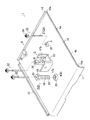
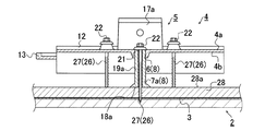
以下、本実施形態の支持瓦1の構成について、主に図1乃至図6に基づいて説明する。ここで、図1は本実施形態の支持瓦1の構成を示す分解斜視図であり、図2は支持瓦1を屋根構造体2の屋根面3に取付た状態を示す側方から視た断面図であり、図3は支持瓦1の構成を示す平面図であり、図4は支持瓦1の傾斜調整ボルト7aの別例構成を示す正面から視た断面図であり、図5及び図6は傾斜調整ボルト7b,7cの別例構成を示す(a)斜視図、及び(b)平面図である。ここで、本実施形態の支持瓦1は、建築物の屋根構造体2の傾斜した屋根面3に設置されるものであり、通常の瓦Kが規則正しく屋根面3に葺き上がられた中の一部を支持瓦1に交換したものである。なお、本実施形態の支持瓦1は、屋根面3の上に設置される太陽電池モジュール(屋根上設置物に相当(図示しない))を固定して支持するものであり、屋根面3に複数の支持瓦1が所定の間隔で配設されているものについて例示するものとする。なお、説明を簡略化するため、一の支持瓦1に着目し以下に説明を行うものとする。
Hereinafter, the configuration of the
本実施形態の支持瓦1は、図1乃至図3等に主に示されるように、金属製の瓦本体4と、瓦本体4の本体上面4aから上方に向かって突設され、瓦本体4と一体的に形成された支持部5と、支持部5の取付位置に近接して設けられた貫通孔部6及び貫通孔部6と螺合可能な傾斜調整ボルト7を有する傾斜調整部8と、支持部5を挟んで貫通孔部6と相対する位置に左右対称に設けられた一対の釘孔部9とを具備して主に構成されている。
As shown mainly in FIGS. 1 to 3 and the like, the
さらに各構成について詳述すると、瓦本体4は、屋根面3に葺き上げられる複数の通常の瓦K(陶器製の瓦に相当)と略同一の形状を模して構成され、本体上面4aで支持部5が突設された略平板状の本体部10と、本体部10の下端の瓦下端部10aから下方に向かって直交方向に曲折された瓦下辺部11と、本体部10の上端の瓦上端部10bから上方及び下方に向かって直交方向にそれぞれ延設された瓦上辺部12と、本体部10の一方の側端に設けられ、互いに隣接し上方から重ねられた通常の瓦Kの側部(図示しない)を支持する瓦側辺部13とを具備し、金属製素材によって一体的に形成されている。また、本体部10の瓦上端部10bの近傍には、屋根構造体2の横方向(水平方向)に沿って形成された桟木14の位置に対応して釘打ちが可能な桟木用孔部15が本体部10(瓦本体4)を貫通して設けられている。
Furthermore, each structure will be described in detail. The tile
一方、瓦本体4の本体上面4aの略中央位置から突設された支持部5は、側方から視ると断面コの字形状を呈し、開口部16が上方に位置するように設置されている。ここで、本体上面4aから垂設され互いに離間した一対の支持脚部17a,17bは、本体上面4aに沿った連結部23を介して連結されている。係る支持部5により、屋根上設置物を各種固定部材(図示しない)を介して接続し支持脚部17a,17bの間で挟んで、固定することができる。支持部5の構成は、周知のため、ここでは詳細な説明は省略するものとする。
On the other hand, the
傾斜調整部8は、前述したように、貫通孔部6及び傾斜調整ボルト7を組合わせて構築されている。ここで、貫通孔部6は、瓦本体4の本体部10の中央部よりやや下方位置であり、瓦本体4の中心線に沿った位置に本体上面4a及び本体下面4bを貫通して形成されている。すなわち、本体上面4aに設けられた支持部5よりも僅かに下位置に設けられている。円形状の貫通孔部6は、その内周面に所定のピッチで形成された雌ねじが設けられている。一方、傾斜調整ボルト7は、六角柱形状のボルト頭部18と、ボルト頭部18から突設された長棒状のボルト軸19とを具備して構成されている。ここで、ボルト軸19の軸周面には貫通孔部6の雌ねじに螺合可能な雄ねじが形成されている。これにより、貫通孔部6にボルト軸19の軸端部20を挿し込んで回転させることにより、貫通孔部6に沿ってボルト軸19が回転し、螺合推進力が発生することになる。
As described above, the
さらに、上記傾斜調整ボルト7には、ボルト頭部18及びボルト軸19をボルト軸方向に沿って貫通したボルト釘孔部21が設けられている(図2等参照)。これにより、支持瓦1を屋根構造体2に固定する際の固定釘22を当該ボルト釘孔部21に挿し込むことができる。
Further, the
加えて、瓦本体4は、支持部5の設けられた本体部10の中央から瓦上端側に移動した位置に、瓦本体4の中心線から互いに左右方向にそれぞれ離間した一対の釘孔部9が本体上面4a及び本体下面4bを貫通するように設けられている。ここで、釘孔部9及び先に述べた傾斜調整部8の貫通孔部6は、本体上面4aから僅かに突出し、側方視で断面略台形状となる固定釘22の釘頭24と当接する当接受部25が設けられている。さらに、釘孔部9及び前述したボルト釘孔部21に挿通可能な固定釘22は、釘孔部9等よりも広径の釘頭24と、釘頭24から延設され、先端が尖鋭状に形成された長軸状の釘軸26とを具備して構成され、尖鋭状の釘軸26の先端から略中央付近まで、螺旋状に形成されたねじ山部27が形成されている。
In addition, the
さらに、本実施形態の支持瓦1は、屋根構造体2の屋根面3に当該支持瓦1を設置する際に、貫通孔部6の設けられた本体下面4bと、相対する屋根面3との間に平板状のスペーサ部材28が介設されている。係るスペーサ部材28は、傾斜調整部8によって支持瓦1(瓦本体4)の傾斜を変化させるため、傾斜調整ボルト7のボルト軸19の軸長さと支持瓦1の瓦本体4と屋根面3との間の距離を考慮して設けられたものである。したがって、傾斜調整ボルト7のボルト軸19が著しく長いものを使用する必要がない。
Furthermore, when the
次に、本実施形態の支持瓦1を利用した、屋根構造体2の屋根面3に対する設置方法の例について説明する。始めに、従来の支持瓦と同様に、支持瓦1を取付ける位置に相当し交換の対象となる通常の瓦(図示しない)を屋根面3から取り外す。このとき、交換対象の通常の瓦の左右に位置する瓦を合わせて取り外して上記スペーサ部材28を設ける。そして、通常の瓦Kの取り外しによって空いたスペースに本実施形態の支持瓦1を設置する。
Next, the example of the installation method with respect to the
具体的に説明すると、通常の瓦Kが取り外された場所に、支持瓦1(瓦本体4及び支持部5に相当)の瓦上端が、上方に位置する通常の瓦Kの瓦下端の下になるように、支持瓦1及び通常の瓦Kを重ね合わせる。ここで、瓦本体4の本体部10の瓦上端部10bは、先に述べた屋根構造体2の一部構成をなす桟木14の上に載置される。さらに、瓦上辺部1すなわち、瓦上端部10bは、通常の瓦K及び桟木14の間に挟まれた状態となる(図2参照)。このとき、瓦本体4の瓦上辺部12によって通常の瓦Kとの間の位置がずれることなく安定した状態に保持される。
More specifically, the upper end of the support tile 1 (corresponding to the
一方、瓦本体4の下側の瓦下辺部11は、下方に位置する通常の瓦Kの瓦面と当接している。さらに、瓦本体4の側方(図3における紙面左方向)に設けられた瓦側辺部13は、隣接する通常の瓦Kの側部(図示しない)が載せられている。一方、瓦本体4の反対側の側方(図3における紙面右方向)は、隣接する通常の瓦Kの上に重ねられている。これにより、上下及び左右に位置する通常の瓦Kの間に瓦本体4が設置される。このとき、瓦本体4自体は単に屋根面3に載置されたに過ぎず、何ら固定手段を介して固定されていない。そして、支持部5の下方位置に貫設された貫通孔部6に傾斜調整ボルト7のボルト軸19の軸端部20を挿込み、係る状態でボルト頭部18を時計方向に回転させる。これにより、ボルト軸19の雄ねじと貫通孔部6の雌ねじが螺合する。そして、回転を継続することにより、ボルト軸19の軸端部20が徐々に下方に移動する。その後、瓦本体4と屋根面3との間に介設されたスペーサ部材28のスペーサ面28aに軸端部20が到着する。この状態で、さらにボルト頭部18を回転させてもスペーサ部材28によって軸端部20がさらに下方に移動する動きは規制される。その結果、ボルト軸19と螺合した貫通孔部6を介して瓦本体4が上方に向かって移動する力が作用する(図2における矢印A参照)。ここで、瓦本体4は、傾斜した屋根面3に沿って設置され、さらに瓦上端部10bが上方位置の通常の瓦K及び屋根構造体2の桟木14の間に挟まれている。そのため、係る部位を軸として、瓦本体4の瓦下端部10a側が浮き上がるようになる。その結果、屋根面3に対する瓦本体4(支持瓦1)の傾斜角度を変化させることができる(図2におけるθ参照)。これに伴い、瓦本体4の下方に位置する瓦下辺部11と通常の瓦Kの間に空隙が生じ(図2における破線円中の矢印B参照)、支持瓦1と通常の瓦Kとが直に接触することがない。その結果、支持瓦1によって支持される屋根上設置物の荷重が、陶器製の通常の瓦Kに加わることがなく、通常の瓦Kの破損を防ぐことができる。なお、支持瓦1の傾斜角度、すなわち、支持瓦1の瓦下辺部11と通常の瓦Kとの間の空隙量は、傾斜調整ボルト7の貫通孔部6に対する回転に応じて任意に変化させることができ、詳細な設定が可能となる。
On the other hand, the
空隙の調整が完了した後、瓦本体4に貫設された一対の釘孔部9及び傾斜調整ボルト7のボルト釘孔部21のそれぞれに、固定釘22を挿し込み、先端のねじ山部27が屋根構造体2に到達するまでねじ固定する。なお、ボルト釘孔部21に挿し込まれた固定釘22は、傾斜調整ボルト7の軸端部20が当接するスペーサ部材28を貫通し、屋根構造体7まで到達するようにして固定されている。また、図2等において図示しないが、瓦上端部10bが載置された桟木14に対向する位置に設けられた桟木用孔部15にも同様に固定釘22による固定が行われる。その結果、支持瓦1が屋根構造体2に強固に固定されたことになる。
After the adjustment of the air gap is completed, the fixing
以上説明したように、本実施形態の支持瓦1を使用することで、設置する屋根構造体2の屋根面3に対する傾斜を所定の範囲で任意に変化させることができ、支持瓦1の下方に位置する通常の瓦Kとの間に予め規定した量の空隙(矢印B参照)を形成することができる。特に、本実施形態の支持瓦1の場合、傾斜調整部8の傾斜調整ボルト7及び貫通孔部6の間の螺合推進力を利用することで、瓦本体4の瓦下端部10aを上方に浮き上がらせることができ、空隙量の微調整を容易に行うことができる。そのため、従来のように、左右に位置する通常の瓦Kを取り外し、かつ再び元の状態に戻す作業を省略することができ、作業時間を大幅に短縮することができる。さらに、傾斜調整ボルト7の貫通孔部6に対する回転量に応じて傾斜角度を精細に調整することができ、従来のくさび形状の高さ調整部材を用いるものよりも精度の高い調整を短時間で行うことができる。
As described above, by using the
加えて、傾斜調整ボルト7に固定釘22の挿通可能なボルト釘孔部21を貫設することで、支持瓦1を固定するための釘孔部9を共用化し、釘孔部9を設ける作業を省力化することができる。さらに、支持瓦1の美観を損なうことがない。さらに、屋根上設置物を設置した後に、空隙の微調整が必要となる場合であっても、従来に比べて作業量及び作業時間を大幅に削減することができる。
In addition, a bolt
以上、本発明について好適な実施形態を挙げて説明したが、本発明はこれらの実施形態に限定されるものではなく、以下に示すように、本発明の要旨を逸脱しない範囲において、種々の改良及び設計の変更が可能である。 The present invention has been described with reference to preferred embodiments. However, the present invention is not limited to these embodiments, and various modifications can be made without departing from the spirit of the present invention as described below. And design changes are possible.
すなわち、本実施形態の支持瓦1において、傾斜調整ボルト7のボルト頭部18が瓦本体4の本体上面4aに露出するものを示したが、これに限定されるものではなく、例えば、図4に示すように、ボルト頭部18aを瓦本体4及びスペーサ部材28の間に介在させるものであっても構わない。この場合、傾斜調整ボルト7aの回転によって、ボルト頭部18aの位置が下方に移動し、スペーサ部材28と当接することになる。特に、支持瓦1を固定するための固定釘22の高さ位置を揃えることができるため、支持瓦1の設置状態における美観を向上させることができる。
That is, in the
ここで、上記構成の場合、ボルト軸19aの軸端部に何ら処理が施されていないと、傾斜調整ボルト7aを貫通孔部6に対して回転させることができない。そこで、例えば、図5及び図6に示すように、軸端部20b,20cの表面に六角形状の六角孔部29や直線上の溝30を設けた傾斜調整ボルト7b,7cを使用するものであっても構わない。これにより、既存の六角レンチやマイナスドライバー等の周知の工具を利用して傾斜調整ボルト7b,7cを貫通孔部6に螺合されたボルト軸19b,19cに沿って回転させることができる。ここで、六角孔部29や溝30が本発明における回転操作部に相当する。
Here, in the case of the above configuration, the
さらに、本実施形態の支持瓦1において、図1乃至図3等に示すように、三本の固定釘22を利用して支持瓦1を屋根構造体2に固定するものを示したが、これに限定されるものではなく、例えば、図7に示すように、支持部5の周囲に四つの釘孔部9を設け、四本の固定釘22を利用する支持瓦1aを構成するものであってもよい。係る場合、図1等において示した傾斜調整ボルト7の長さ方向にボルト釘孔部21を形成する必要がなく、四つの釘孔部9に挿通された四本の固定釘22によって、支持瓦1を屋根構造体2の屋根面3に確実に固定することができる。なお、図7の別例構成の支持瓦1aにおいて、本実施形態の支持瓦1と同一の構成については同一番号を付し、詳細な説明は省略するものとする。
Further, in the
1 支持瓦
2 屋根構造体
3 屋根面
4 瓦本体
4a 本体上面
4b 本体下面
5 支持部
6 貫通孔部(傾斜調整部)
7,7a,7b,7c 傾斜調整ボルト(傾斜調整部)
8 傾斜調整部
9 釘孔部
10 本体部
10a 瓦下端部
10b 瓦上端部
17a,17b 支持脚部
18,18a,18b,18c ボルト頭部
19,19a,19b,19c ボルト軸
20 軸端部
21 ボルト釘孔部
22 固定釘
27 ねじ山部
29 六角孔部(回転操作部)
30 溝部(回転操作部)
K 通常の瓦(陶器製の瓦)
DESCRIPTION OF
7, 7a, 7b, 7c Tilt adjustment bolt (Tilt adjustment part)
DESCRIPTION OF
30 Groove (Rotation operation part)
K normal roof tile (ceramic tile)
Claims (2)
前記瓦本体の本体上面に形成され、屋根上設置物を固定し支持するための支持部と、
前記瓦本体を貫通し内周面に雌ねじが形成された貫通孔部、及び、前記貫通孔部と螺合可能な雄ねじがボルト軸の周面に形成され、前記ボルト軸の軸方向に沿って貫設され前記瓦本体を前記屋根面に固定する固定釘を挿通可能なボルト釘孔部を備える傾斜調整ボルトを有し、前記屋根面に対する前記瓦本体の傾斜を調整し、前記瓦本体の瓦下辺部と重ねられる瓦との間の空隙を形成する傾斜調整部と、
前記瓦本体に貫設され、前記固定釘を挿通可能な複数の釘孔部と
を具備することを特徴とする支持瓦。 A tile body installed on the roof surface of the roof structure;
Formed on the top surface of the tile body, and a support part for fixing and supporting the installation on the roof;
A through-hole portion that penetrates the roof tile body and has an internal thread formed on the inner peripheral surface thereof, and a male screw that can be screwed into the through-hole section are formed on the peripheral surface of the bolt shaft, along the axial direction of the bolt shaft. has penetrated to tilt adjustment bolt pre Kikawara body comprising a can be inserted bolt nail hole section solid Teikugi be fixed to the roof surface, to adjust the inclination of the tile main body with respect to the roof surface, the tile main body An inclination adjusting portion that forms a gap between the tile lower side of the tile and the tile to be stacked,
Support tile that the tile body is pierced, characterized by comprising a front Symbol inserted through the locking nail possible plurality of nail hole portions.
前記ボルト軸の軸端部が前記瓦本体の前記本体上面から突出するように前記貫通孔部に螺合され、
前記軸端部に設けられ、前記傾斜調整ボルトを回転させるための回転操作部をさらに具備することを特徴とする請求項1に記載の支持瓦。 The tilt adjusting bolt is
The shaft end of the bolt shaft is screwed into the through hole so as to protrude from the top surface of the main body of the roof tile body,
The support roof tile according to claim 1, further comprising a rotation operation unit that is provided at the end of the shaft and rotates the inclination adjusting bolt.
Priority Applications (3)
| Application Number | Priority Date | Filing Date | Title |
|---|---|---|---|
| JP2011271935A JP5855925B2 (en) | 2011-12-13 | 2011-12-13 | Supporting roof tile |
| PCT/JP2012/079963 WO2013088915A1 (en) | 2011-12-13 | 2012-11-19 | Support tile |
| US14/292,715 US20140259988A1 (en) | 2011-12-13 | 2014-05-30 | Support tile |
Applications Claiming Priority (1)
| Application Number | Priority Date | Filing Date | Title |
|---|---|---|---|
| JP2011271935A JP5855925B2 (en) | 2011-12-13 | 2011-12-13 | Supporting roof tile |
Publications (3)
| Publication Number | Publication Date |
|---|---|
| JP2013124444A JP2013124444A (en) | 2013-06-24 |
| JP2013124444A5 JP2013124444A5 (en) | 2015-01-29 |
| JP5855925B2 true JP5855925B2 (en) | 2016-02-09 |
Family
ID=48612370
Family Applications (1)
| Application Number | Title | Priority Date | Filing Date |
|---|---|---|---|
| JP2011271935A Active JP5855925B2 (en) | 2011-12-13 | 2011-12-13 | Supporting roof tile |
Country Status (3)
| Country | Link |
|---|---|
| US (1) | US20140259988A1 (en) |
| JP (1) | JP5855925B2 (en) |
| WO (1) | WO2013088915A1 (en) |
Families Citing this family (4)
| Publication number | Priority date | Publication date | Assignee | Title |
|---|---|---|---|---|
| WO2013131572A1 (en) * | 2012-03-08 | 2013-09-12 | Nesboe Paul Arne | Adjustable support device for a frame member and installation method |
| KR102419365B1 (en) * | 2014-08-29 | 2022-07-11 | 유한회사 중앙강재 | Snow melting roof tile and roof snow melting system including the same |
| CN110821053A (en) * | 2016-02-24 | 2020-02-21 | 北京利泰装饰工程有限公司 | Roofing system structure |
| US9853595B1 (en) * | 2016-08-18 | 2017-12-26 | Yanegijutsukenkyujo Co., Ltd. | Fixture for on-roof installation object and fixing structure of on-roof installation object |
Family Cites Families (13)
| Publication number | Priority date | Publication date | Assignee | Title |
|---|---|---|---|---|
| US2940784A (en) * | 1956-06-06 | 1960-06-14 | William B Fell | Precision threaded adjustment |
| US3376683A (en) * | 1965-10-23 | 1968-04-09 | Alside Inc | Leveling means for aluminum siding panel |
| US4108407A (en) * | 1975-07-14 | 1978-08-22 | Rca Corporation | Adjustment device |
| JPH09184249A (en) * | 1995-12-28 | 1997-07-15 | Yane Gijutsu Kenkyusho:Kk | Support roof tile laying structure and support roof tile |
| JP3450123B2 (en) * | 1996-06-05 | 2003-09-22 | 株式会社屋根技術研究所 | Support tile |
| JPH1068193A (en) * | 1996-08-27 | 1998-03-10 | Yoshitaka Yoshinari | Support roof tile |
| US6024330A (en) * | 1998-05-27 | 2000-02-15 | International Business Machines Corporation | Uni-axial floor anchor and leveler for racks |
| CA2409312C (en) * | 2000-05-25 | 2010-09-07 | John Repasky | Ballast block deck system and pedestal assembly therefor |
| US6826878B1 (en) * | 2001-06-28 | 2004-12-07 | John Rovtar | Window shim |
| US7987637B2 (en) * | 2006-09-25 | 2011-08-02 | Smith Patrick J | Adjustable shim |
| JP2009293201A (en) * | 2008-06-03 | 2009-12-17 | Yane Gijutsu Kenkyusho:Kk | Supporting structure of heat insulation unit |
| JP4721081B1 (en) * | 2010-04-28 | 2011-07-13 | 株式会社A−スタイル | Support and fixing structure of solar energy device |
| US8136311B2 (en) * | 2011-04-01 | 2012-03-20 | Jun Liu | Solar panel and equipment mounting apparatus for roofs |
-
2011
- 2011-12-13 JP JP2011271935A patent/JP5855925B2/en active Active
-
2012
- 2012-11-19 WO PCT/JP2012/079963 patent/WO2013088915A1/en active Application Filing
-
2014
- 2014-05-30 US US14/292,715 patent/US20140259988A1/en not_active Abandoned
Also Published As
| Publication number | Publication date |
|---|---|
| US20140259988A1 (en) | 2014-09-18 |
| JP2013124444A (en) | 2013-06-24 |
| WO2013088915A1 (en) | 2013-06-20 |
Similar Documents
| Publication | Publication Date | Title |
|---|---|---|
| JP4975893B1 (en) | Solar cell module fixing structure | |
| JP5856511B2 (en) | Pile foundation structure | |
| JP5855925B2 (en) | Supporting roof tile | |
| KR101479908B1 (en) | Structures for solar panel installation | |
| WO2017092148A1 (en) | Connector and solar panel installation frame having same | |
| JP5690598B2 (en) | Mounting device for installation on the roof | |
| JP3194864U (en) | Height adjustable pile | |
| KR200458801Y1 (en) | Variable solar module for established inground | |
| KR102112502B1 (en) | Assembled type solar light structure coupled by fastening bolts | |
| JP5976339B2 (en) | Mounting device and mounting method for rooftop equipment installation stand | |
| JP5622709B2 (en) | Supporting frame structure for photovoltaic panel frame | |
| KR20150117513A (en) | Fixing structure for solar cell array of assemble roof | |
| JP5915986B2 (en) | Support structure for solar panels | |
| JP2011122406A (en) | After-fitted on-roof installation object fixing tile, and screw used for the same | |
| JP2007285042A (en) | Mounting structure of solar-cell panel | |
| JP5881121B2 (en) | Panel installation structure | |
| KR20190133933A (en) | Frame strucutre for mounting solar panel to frame | |
| JP5787660B2 (en) | Mounting device for solar cell panel and installation method thereof | |
| JP3185161U (en) | Mounting structure for solar panel mount | |
| JP5067702B1 (en) | Solar panel installation structure | |
| JP2015132088A (en) | Connection member, and structure for connecting foundation pile and support together | |
| JP5734171B2 (en) | Fixture | |
| JP3188906U (en) | Solar panel mount | |
| JP5159430B2 (en) | The basic structure of wooden buildings | |
| JP5699181B2 (en) | Solar panel installation structure |
Legal Events
| Date | Code | Title | Description |
|---|---|---|---|
| A521 | Request for written amendment filed |
Free format text: JAPANESE INTERMEDIATE CODE: A523 Effective date: 20141210 |
|
| A621 | Written request for application examination |
Free format text: JAPANESE INTERMEDIATE CODE: A621 Effective date: 20141210 |
|
| TRDD | Decision of grant or rejection written | ||
| A01 | Written decision to grant a patent or to grant a registration (utility model) |
Free format text: JAPANESE INTERMEDIATE CODE: A01 Effective date: 20151201 |
|
| A61 | First payment of annual fees (during grant procedure) |
Free format text: JAPANESE INTERMEDIATE CODE: A61 Effective date: 20151210 |
|
| R150 | Certificate of patent or registration of utility model |
Ref document number: 5855925 Country of ref document: JP Free format text: JAPANESE INTERMEDIATE CODE: R150 |
|
| R250 | Receipt of annual fees |
Free format text: JAPANESE INTERMEDIATE CODE: R250 |
|
| R250 | Receipt of annual fees |
Free format text: JAPANESE INTERMEDIATE CODE: R250 |