JP5851143B2 - Heat source equipment - Google Patents
Heat source equipment Download PDFInfo
- Publication number
- JP5851143B2 JP5851143B2 JP2011169578A JP2011169578A JP5851143B2 JP 5851143 B2 JP5851143 B2 JP 5851143B2 JP 2011169578 A JP2011169578 A JP 2011169578A JP 2011169578 A JP2011169578 A JP 2011169578A JP 5851143 B2 JP5851143 B2 JP 5851143B2
- Authority
- JP
- Japan
- Prior art keywords
- power
- battery
- heat source
- amount
- commercial
- Prior art date
- Legal status (The legal status is an assumption and is not a legal conclusion. Google has not performed a legal analysis and makes no representation as to the accuracy of the status listed.)
- Active
Links
Images


Description
本発明は給湯装置、温水暖房装置等の熱源装置に関する。 The present invention relates to a heat source device such as a hot water supply device and a hot water heating device.
給湯装置、温水暖房装置等の熱源装置は、電磁弁や電動ポンプ、制御回路ユニット等の種々様々な電子機器を搭載しており、通常、それらの電子機器の電源として、商用電源が利用される。 Heat source devices such as water heaters and hot water heaters are equipped with various electronic devices such as solenoid valves, electric pumps, control circuit units, etc., and commercial power sources are usually used as power sources for these electronic devices. .
また、例えば特許文献1に見られるように、太陽電池や燃料電池により発電した電力を蓄電器に貯蔵しておき、その貯蔵した電力を利用して温水供給を行なうようにしたシステムも知られている。 Moreover, as seen in Patent Document 1, for example, a system is also known in which electric power generated by a solar cell or a fuel cell is stored in a capacitor, and hot water is supplied using the stored electric power. .
商用電源を電源として利用する熱源装置にあっては、商用電源の停電が発生すると、運転を行うことができなくなる。このため、特に災害等により停電が長期にわたるような場合には、熱源装置を長期間、使用することができなくなるという不都合がある。従って、停電時にも、熱源装置の運転をある程度は行ない得るようにすることが望まれる。 In a heat source device that uses a commercial power source as a power source, operation cannot be performed if a power failure occurs in the commercial power source. For this reason, there is an inconvenience that the heat source device cannot be used for a long period of time, especially when a power outage is prolonged due to a disaster or the like. Therefore, it is desired that the heat source device can be operated to some extent even during a power failure.
一方、特許文献1に見られるように、太陽電池や燃料電池により発電した電力を蓄電器に貯蔵するものでは、商用電源の停電時でもシステムの運転を行なうことは可能である。 On the other hand, as can be seen in Patent Document 1, in the case where power generated by a solar cell or a fuel cell is stored in a capacitor, the system can be operated even when a commercial power supply fails.
しかるに、太陽電池の発電量は天候の影響を受け、システムの運転を十分に行い得るような電力を太陽電池によって発電するためには、天候条件が良い場合であっても、大型なサイズの太陽電池を必要する。このため、該太陽電池自体のコストやその設置コストが高価なものとなる。 However, the amount of power generated by solar cells is affected by the weather, and in order to generate power with solar cells that can sufficiently operate the system, even if the weather conditions are good, large-sized solar I need a battery. For this reason, the cost of this solar cell itself and its installation cost become expensive.
さらに、特許文献1のものは、太陽電池以外に燃料電池を備えるものの、太陽電池の発電量が不足する場合でも、十分な電力を発電し得るような燃料電池は、一般に極めて高価である。 Furthermore, although the thing of patent document 1 is equipped with a fuel cell other than a solar cell, even when the power generation amount of a solar cell is insufficient, the fuel cell which can generate | occur | produce sufficient electric power is generally very expensive.
従って、特許文献1に見られる如きシステムは、汎用的な給湯装置等の熱源装置に比して大幅に高価なものとならざるを得ず、多くのユーザが購入することは難しい。 Therefore, the system as shown in Patent Document 1 must be significantly more expensive than a heat source device such as a general-purpose hot water supply device, and is difficult for many users to purchase.
そこで、例えば、商用電源を電源として利用する通常の熱源装置において、屋外に設置される熱源機に、蓄電器とこれに充電する電力を発電する太陽電池とを搭載しておき、商用電源の停電時に、蓄電器から供給し得る電力の範囲内で、熱源装置の運転を行い得るようにすることが考えられる。 Therefore, for example, in a normal heat source device that uses a commercial power source as a power source, a heat source device installed outdoors is equipped with a capacitor and a solar cell that generates electric power to be charged to the power source. It is conceivable that the heat source device can be operated within the range of electric power that can be supplied from the battery.
このような熱源装置では、商用電源の停電時に、熱源装置の運転に伴う電力消費によって蓄電器に貯蔵されている電力が不足すると、熱源装置の運転を行うことができなくなるものの、その後、太陽電池の電力を蓄電器に充電することができるので、該熱源装置の運転を繰り返し行なうことが可能となる。 In such a heat source device, if the power stored in the capacitor is insufficient due to the power consumption associated with the operation of the heat source device during a power failure of the commercial power supply, the heat source device cannot be operated, but then the solar cell Since electric power can be charged in the battery, the operation of the heat source device can be repeated.
ただし、このような熱源装置では、停電時に、ユーザが任意のタイミングで熱源装置の運転を行なおうとしても、蓄電器の充電状態によっては、その時点では、蓄電器の電力が不足していて熱源装置の運転を行うことができないという状況や、熱源装置の運転を開始できても、その開始時における蓄電器の電力が少ないために、その後、直ぐに熱源装置の運転を行うことができなくなってしまうという状況が発生する恐れがあることを認識できない。 However, in such a heat source device, even if the user tries to operate the heat source device at an arbitrary timing in the event of a power failure, depending on the state of charge of the capacitor, the power of the capacitor is insufficient at that time, and the heat source device The situation that the operation of the heat source device cannot be performed, or even if the operation of the heat source device can be started, the power of the condenser is small at the start, and then the heat source device cannot be operated immediately thereafter Cannot recognize that there is a risk of occurrence.
従って、ユーザが、熱源装置の運転を、ある程度継続して行い得る状況を容易に認識し得るようにすることが望まれる。 Therefore, it is desired that the user can easily recognize a situation in which the operation of the heat source device can be continued to some extent.
本発明はかかる背景に鑑みてなされたものであり、停電時に、蓄電装置の電力によって熱源装置の運転を繰り返し行なうことができると共に、その停電時の運転をユーザにとって利用し易い形態で実現することができる熱源装置を提供することを目的とする。 The present invention has been made in view of such a background, and at the time of a power failure, the operation of the heat source device can be repeatedly performed by the power of the power storage device, and the operation at the time of the power failure is realized in a form that is easy for the user to use. An object of the present invention is to provide a heat source device capable of performing the above.
本発明の熱源装置は、かかる目的を達成するために、屋外に設置され、商用電源の電力の給電を受けた状態で、屋内に供給する熱媒体を燃焼熱により加熱する熱源機と、該熱源機の運転操作を行うために屋内に設置されるリモコンユニットとを備える熱源装置であって、
前記熱源機に搭載された太陽電池と、
該太陽電池の発電電力が充電されるように該太陽電池に接続されており、前記商用電源の電力の代用として熱源機の運転を行わせるための電力を貯蔵する蓄電器と、
前記蓄電器の蓄電量を観測する蓄電量観測手段と、
前記商用電源の停電時に、該蓄電量観測手段により観測された前記蓄電器の蓄電量に応じた報知を、前記リモコンユニットに設けられた報知器を介して行なう報知制御手段と、
前記商用電源の非停電時に、前記蓄電量観測手段により観測された前記蓄電器の蓄電量に応じて、熱源機の運転を行なうために使用する電源電力を、前記商用電源の電力と前記蓄電器との電力とのうちの一方から他方に切替える電源電力切替手段とを備えており、
前記商用電源の停電時には、前記蓄電器の蓄電量が所定の第1閾値に低下するまで、該蓄電器の電力を使用して前記熱源機の運転を実行可能であり、前記商用電源の非停電時に、前記電源電力切替手段により前記電源電力が前記商用電源の電力から前記蓄電器の電力に切替えられた状態では、該蓄電器の蓄電量が前記第1閾値よりも大きい所定の第2閾値に低下するまで、該蓄電器の電力を使用して前記熱源機の運転を実行可能であるように構成されていることを特徴とする(第1発明)。
In order to achieve the above object, the heat source device of the present invention is installed outdoors and receives heat from a commercial power source. The heat source apparatus heats a heat medium supplied indoors by combustion heat, and the heat source. A heat source device comprising a remote control unit installed indoors for operating the machine,
A solar cell mounted on the heat source device;
A capacitor that is connected to the solar cell so that the generated power of the solar cell is charged, and stores electric power for operating the heat source device as a substitute for the electric power of the commercial power source;
A storage amount monitoring means for observing a storage amount of the capacitor;
Notification control means for performing notification according to the storage amount of the capacitor observed by the storage amount observation means at the time of a power failure of the commercial power source via a notification device provided in the remote control unit ;
When the commercial power source is not powered down, the power source power used for operating the heat source unit according to the power storage amount of the power storage unit observed by the power storage amount observation means is the power of the commercial power source and the power storage unit. Power supply power switching means for switching from one of the power to the other, and
At the time of a power failure of the commercial power supply, the heat source device can be operated using the power of the power storage device until the amount of power stored in the power storage device falls to a predetermined first threshold. In the state where the power source power is switched from the power of the commercial power source to the power of the battery by the power source power switching means, until the amount of power stored in the battery decreases to a predetermined second threshold value greater than the first threshold value, It is configured such that the operation of the heat source device can be executed using the electric power of the battery (first invention).
かかる第1発明によれば、商用電源の停電時には、蓄電器の電力を商用電源の電力の代わりに使用して、熱源機の運転が行われる。この場合、蓄電器は、前記太陽電池に接続されているので、熱源機の運転を行なっていない状況では、該太陽電池の発電電力が蓄電器に充電されることとなる。この充電によって、蓄電器の電力を使用した熱源機の運転を繰り返し行なうことが可能となる。 According to the first invention, at the time of a power failure of the commercial power supply, the heat source device is operated by using the power of the storage battery instead of the power of the commercial power supply. In this case, since the storage battery is connected to the solar battery, the generated power of the solar battery is charged to the storage battery when the heat source device is not operated. By this charging, it becomes possible to repeatedly operate the heat source device using the electric power of the battery.
そして、蓄電器の蓄電量は、前記蓄電量観測手段によって観測され、この観測された蓄電量に応じた報知が、屋内に設置されているリモコンユニットに設けられた報知器を介して行なわれる。 The amount of electricity stored in the electricity storage device is observed by the electricity storage amount observation means, and notification according to the observed amount of electricity storage is performed via an alarm device provided in a remote control unit installed indoors.
この報知によって、ユーザは、蓄電器の蓄電量がどのような状態であるか、例えば、熱源機の運転を行い得る程度に十分な蓄電量であるか否か等を屋内において認識することができる。 By this notification, the user can recognize indoors whether the power storage amount of the power storage unit is in a state, for example, whether the power storage amount is sufficient to operate the heat source device.
このため、ユーザは、闇雲に熱源機の運転を行わせようとしたり、あるいは、太陽電池による蓄電器の充電を不必要に長時間にわたって待ったりすることなく、熱源機の運転を行うようにすることができる。 For this reason, the user may try to operate the heat source unit without causing the dark clouds to operate the heat source unit, or waiting for an unnecessarily long time to charge the battery with a solar cell. it can.
よって、第1発明によれば、商用電源の停電時に、蓄電装置の電力によって熱源装置の運転を繰り返し行なうことができると共に、その停電時の運転をユーザにとって利用し易い形態で実現することができる。 Therefore, according to the first invention, the operation of the heat source device can be repeatedly performed by the power of the power storage device at the time of a power failure of the commercial power supply, and the operation at the time of the power failure can be realized in a form that is easy for the user to use. .
また、蓄電器は停電時に熱源機の運転を、長時間にわたって行わせることができるような大容量のものである必要は無いので、該蓄電器やこれを充電する太陽電池は比較的小型で安価なものを採用することができる。
また、第1発明によれば、商用電源の非停電時において、蓄電器の蓄電量に応じて、熱源機の運転を行なうために使用する電源電力を、前記商用電源の電力から前記蓄電器の電力に切替えたり、該蓄電器の電力から商用電源の電力に切替えるようにすることができる。例えば、蓄電器の蓄電量が第1の所定量以上である場合(蓄電器の充電状態が満充電状態もしくはこれに近い状態である場合)に、該蓄電量が、第1の所定量よりも低い第2の所定量に低下するまで、蓄電器の電力を使用して熱源機の運転を行うようにすることができる。
このようにすることにより、商用電源の非停電時において、太陽電池によって充電された蓄電器の電力を使用するようにして、商用電源の電力の消費を低減し、熱源装置の節電を図ることができる。
さらに、第1発明によれば、前記商用電源の停電時には、前記蓄電器の蓄電量が所定の第1閾値に低下するまで、該蓄電器の電力を使用して前記熱源機の運転を実行可能であり、前記商用電源の非停電時に、前記電源電力切替手段により前記電源電力が前記商用電源の電力から前記蓄電器の電力に切替えられた状態では、該蓄電器の蓄電量が前記第1閾値よりも大きい所定の第2閾値に低下するまで、該蓄電器の電力を使用して前記熱源機の運転を実行可能である。
In addition, since it is not necessary for the storage device to have a large capacity so that the operation of the heat source device can be performed for a long time in the event of a power failure, the storage device and the solar cell for charging the storage device are relatively small and inexpensive. Can be adopted .
According to the first invention, when the commercial power source is not powered, the power source power used for operating the heat source device is changed from the commercial power source power to the electric power source power according to the amount of power stored in the capacitor. It can be switched, or the power of the battery can be switched to the power of the commercial power supply. For example, when the storage amount of the battery is greater than or equal to a first predetermined amount (when the state of charge of the capacitor is at or near the fully charged state), the storage amount is lower than the first predetermined amount. The heat source device can be operated using the electric power of the storage battery until it decreases to a predetermined amount of 2.
By doing so, it is possible to reduce power consumption of the commercial power source and save power of the heat source device by using the power of the storage battery charged by the solar cell at the time of non-power failure of the commercial power source. .
Furthermore, according to the first invention, at the time of a power failure of the commercial power supply, the operation of the heat source device can be executed using the electric power of the electric storage device until the amount of electric storage of the electric storage device falls to a predetermined first threshold value. In a state in which the power supply power is switched from the power of the commercial power supply to the power of the storage battery by the power supply power switching means at the time of the power failure of the commercial power supply, the storage amount of the storage battery is larger than the first threshold value. The heat source device can be operated using the electric power of the battery until the second threshold value is lowered.
かかる第1発明では、前記報知制御手段は、前記商用電源の停電時に、前記蓄電器の蓄電量が、該蓄電器の電力によって熱源機の運転を行い得る蓄電量であるか否かを判断し、該判断結果が肯定的である場合と否定的である場合とのうちの少なくともいずれか一方の場合にその旨を報知する手段を有することが好ましい(第2発明)。 In the first invention, the notification control means determines whether or not the amount of electricity stored in the capacitor is the amount of electricity that can operate the heat source device with the electric power of the capacitor when the commercial power supply is interrupted, It is preferable to have means for notifying that in the case of at least one of the case where the determination result is affirmative and the case where the determination result is negative (second invention).
この第2発明によれば、ユーザは、停電時に、蓄電器の電力によって熱源機の運転を行い得る状況であるか否かを、報知制御手段による報知によって、正しく認識することができる。このため、太陽電池による蓄電器の充電のために熱源機の運転を行わないようにしてユーザが待機しなければならない時間を必要最小限に留めることができ、停電時における熱源機の運転を行なう頻度を高めることができる。 According to the second aspect of the present invention, the user can correctly recognize whether or not the heat source device can be operated with the electric power of the battery by a notification by the notification control means during a power failure. For this reason, it is possible to keep the time that the user has to wait without performing the operation of the heat source unit for charging the storage battery by the solar battery, and the frequency of the operation of the heat source unit during a power failure Can be increased.
また、上記第1発明又は第2発明では、前記報知制御手段は、前記商用電源の停電時における熱源機の運転開始後に、前記蓄電器の蓄電量が、該蓄電器の電力によって熱源機の運転を行なうことが可能な限界の蓄電量の直前の蓄電量であるか否かを判断し、該判断結果が肯定的である場合と否定的である場合とのうちの少なくともいずれか一方の場合にその旨を報知する手段を有することが好ましい(第3発明)。 In the first invention or the second invention, the notification control means operates the heat source device with the amount of electricity stored in the capacitor using the electric power of the capacitor after the start of operation of the heat source device during a power failure of the commercial power source. It is determined whether or not the storage amount immediately before the limit storage amount is possible, and if the determination result is affirmative or negative, the fact is It is preferable to have means for informing (third invention).
この第3発明によれば、停電時に、蓄電器の電力によって熱源機の運転を行っているときに、その運転による電力消費によって蓄電器の電力が減少して、熱源機の運転を行うことができなくなる状況(蓄電器の蓄電量が前記限界の蓄電量まで減少した状況)に近い状況になると、ユーザは、そのこと(まもなく熱源機の運転を行うことができなくなること)を報知制御手段による報知によって認識することができる。 According to the third aspect of the invention, when the heat source device is operated by the power of the battery during a power failure, the power of the battery is reduced due to the power consumption by the operation, and the heat source machine cannot be operated. When the situation becomes close to the situation (a situation where the amount of electricity stored in the battery has decreased to the limit of the amount of electricity stored), the user recognizes that (the heat source machine will soon not be able to operate) by notification by the notification control means. can do.
このため、熱源機の運転中に、ユーザの事前の認識が無いのに、該熱源機の運転が蓄電器の電力不足によって不意に停止してしまうことが無いようにすることができる。また、熱源機の運転を行うことができなくなる前の熱源機の運転計画をたてやすくなると共に、太陽電池の発電電力による蓄電器の充電を行なうために、熱源機の運転を極力控えるような処置をとることができる。 For this reason, it is possible to prevent the operation of the heat source device from being unexpectedly stopped due to a shortage of electric power of the capacitor, even when the user has no prior recognition during the operation of the heat source device. In addition, it is easier to make an operation plan for the heat source unit before it becomes impossible to operate the heat source unit, and to reduce the operation of the heat source unit as much as possible in order to charge the battery with the power generated by the solar cell. Can be taken.
従って、熱源機の運転を全く行うことができないというような状況が発生するのを極力防止することが可能となる。 Therefore, it is possible to prevent the occurrence of a situation where the operation of the heat source machine cannot be performed at all.
上記第1〜第3発明では、前記報知制御手段は、熱源機の運転を行うために使用する電源電力の切替えを行なう場合に、その旨を報知する手段を有するようにしてもよい(第4発明)。 In the first to third aspects of the invention , the notification control means may have means for notifying that when the power source power used for operating the heat source machine is switched ( fourth). invention).
この第4発明によれば、商用電源の非停電時に、ユーザは報知制御手段による報知によって、熱源機の運転が、商用電源の電力を使用して行なわれているか、蓄電器の電力を使用して行なわれているかを認識することができる。このため、ユーザは、熱源装置の節電機能が作動しているか否かを認識することができる。
また、本発明の熱源装置は、商用電源の電力の給電を受けた状態で、熱媒体を燃焼熱により加熱する熱源機と、該熱源機の運転操作を行うためのリモコンユニットとを備える熱源装置であって、前記商用電源の電力の代用として熱源機の運転を行わせるための電力を貯蔵する蓄電器と、前記蓄電器の蓄電量を観測する蓄電量観測手段と、前記商用電源の停電時に、該蓄電量観測手段により観測された前記蓄電器の蓄電量に応じた報知を、前記リモコンユニットに設けられた報知器を介して行なう報知制御手段と、前記商用電源の非停電時に、前記蓄電量観測手段により観測された前記蓄電器の蓄電量に応じて、熱源機の運転を行なうために使用する電源電力を、前記商用電源の電力と前記蓄電器との電力とのうちの一方から他方に切替える電源電力切替手段とを備えており、前記商用電源の停電時には、前記蓄電器の蓄電量が所定の第1閾値に低下するまで、該蓄電器の電力を使用して前記熱源機の運転を実行可能であり、前記商用電源の非停電時に、前記電源電力切替手段により前記電源電力が前記商用電源の電力から前記蓄電器の電力に切替えられた状態では、該蓄電器の蓄電量が前記第1閾値よりも大きい所定の第2閾値に低下するまで、該蓄電器の電力を使用して前記熱源機の運転を実行可能であるように構成されていることを特徴とする(第5発明)。
この第5発明によれば、前記商用電源の停電時に、前記蓄電器の蓄電量に応じた報知が、前記リモコンユニットに設けられた報知器を介して行なわれる。この報知によって、第1発明と同様に、ユーザは、蓄電器の蓄電量がどのような状態であるか、例えば、熱源機の運転を行い得る程度に十分な蓄電量であるか否か等を屋内において認識することができる。
また、第5発明によれば、商用電源の非停電時において、蓄電器の蓄電量に応じて、熱源機の運転を行なうために使用する電源電力を、前記商用電源の電力から前記蓄電器の電力に切替えたり、該蓄電器の電力から商用電源の電力に切替えるようにすることができる。
さらに、第5発明によれば、前記商用電源の停電時には、前記蓄電器の蓄電量が所定の第1閾値に低下するまで、該蓄電器の電力を使用して前記熱源機の運転を実行可能であり、前記商用電源の非停電時に、前記電源電力切替手段により前記電源電力が前記商用電源の電力から前記蓄電器の電力に切替えられた状態では、該蓄電器の蓄電量が前記第1閾値よりも大きい所定の第2閾値に低下するまで、該蓄電器の電力を使用して前記熱源機の運転を実行可能である。
According to the fourth aspect of the present invention, when the commercial power source is not powered down, the user is informed by the notification control means that the operation of the heat source unit is performed using the power of the commercial power source or the power of the battery is used. You can recognize what is happening. For this reason, the user can recognize whether the power saving function of the heat source device is operating.
Further, the heat source device of the present invention includes a heat source device that heats a heat medium with combustion heat in a state where power is supplied from a commercial power source, and a remote control unit for operating the heat source device. A power storage device for storing power for operating a heat source device as a substitute for the power of the commercial power source, a storage amount monitoring means for observing a storage amount of the storage device, and a power failure of the commercial power source, Notification control means for performing notification according to the storage amount of the storage device observed by the storage amount observation means via the notification device provided in the remote control unit; and when the commercial power source is not powered down, the storage amount observation means The power source power used for operating the heat source unit is switched from one of the power of the commercial power source and the power of the capacitor to the other according to the amount of power stored in the capacitor observed by Power switching means, and during the power failure of the commercial power source, the heat source device can be operated using the power of the battery until the amount of power stored in the battery decreases to a predetermined first threshold. In a state in which the power supply power is switched from the power of the commercial power supply to the power of the storage battery by the power supply power switching means at the time of the power failure of the commercial power supply, the storage amount of the storage battery is larger than the first threshold value. The heat source device can be operated using the electric power of the battery until the second threshold value is reduced to the second threshold value ( fifth invention).
According to the fifth aspect of the invention, at the time of a power failure of the commercial power supply, notification according to the amount of power stored in the battery is performed via the alarm provided on the remote control unit. By this notification, as in the case of the first invention, the user can indicate in what state the amount of electricity stored in the battery is, for example, whether the amount of electricity is sufficient to allow the heat source device to operate. Can be recognized .
According to the fifth aspect of the present invention, when the commercial power source is not powered down, the power source power used for operating the heat source device is changed from the commercial power source power to the power source power according to the amount of power stored in the power source. It can be switched, or the power of the battery can be switched to the power of the commercial power supply.
Further, according to the fifth invention, at the time of a power failure of the commercial power supply, the operation of the heat source unit can be executed using the electric power of the battery until the amount of power stored in the battery decreases to a predetermined first threshold value. In a state in which the power supply power is switched from the power of the commercial power supply to the power of the storage battery by the power supply power switching means at the time of the power failure of the commercial power supply, the storage amount of the storage battery is larger than the first threshold value. The heat source device can be operated using the electric power of the battery until the second threshold value is lowered.
本発明の一実施形態を図1〜図6を参照して以下に説明する。本実施形態の熱源装置は、給湯装置1である。この給湯装置1は、図1に示すように、熱媒体としての水を加熱する給湯器本体2と、この給湯器本体2の運転操作を行うための複数のリモコンユニット3(3a,3b)とを備えている。各リモコンユニット3(以降、単にリモコン3という)は、それぞれに内蔵された後述の回路ユニットが給湯器本体2に搭載された回路ユニット4に、リモコンケーブル5を介して電気的に接続されており、このリモコンケーブル5を介して給湯器本体2の回路ユニット4から電源電力の供給を受けたり、該回路ユニット4との間で通信を行なうことが可能となっている。
An embodiment of the present invention will be described below with reference to FIGS. The heat source device of the present embodiment is a hot water supply device 1. As shown in FIG. 1, the water heater 1 includes a
給湯器本体2は、屋外に設置される熱源機であり、水道管から供給される水を、図示を省略するバーナの燃焼熱により熱交換器を介して加熱し、加熱した湯を屋内の台所や、洗面所、浴室等に給湯するように構成されている。上記バーナは本実施形態の例では、燃料としてガスを使用するガスバーナである。かかる給湯器本体2の機構的な構成(バーナの燃焼や給湯に関する機構的な構成)は公知のものであるので、本明細書での詳細な説明は省略する。
The
なお、上記バーナは燃料として灯油等の液体燃料を使用するものであってもよい。 The burner may use liquid fuel such as kerosene as fuel.
本実施形態では、この給湯器本体2には、商用電源の停電時に給湯器本体2の運転を行わせるための電力を貯蔵する蓄電器としてのバッテリ6と、このバッテリ6に充電する電力を発電する太陽電池7とが搭載されている。
In the present embodiment, the water heater
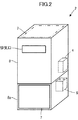
バッテリ6は、図2に示すように給湯器本体2の筐体8内に配置されている。このバッテリ6は、本実施形態では、充電可能な二次電池により構成されたものである。なお、バッテリ6の代わりに、大容量コンデンサにより構成された蓄電器、あるいは、該コンデンサと二次電池とを組み合わせて構成された蓄電器を給湯器本体2に搭載してもよい。
The battery 6 is arrange | positioned in the housing | casing 8 of the water heater
太陽電池7は、パネル状に形成されたモジュール構造のものであり、給湯器本体2の筐体8の外表面のうち、太陽光の照射を受けやすい箇所、例えば筐体8の下部の前板パネル8aの外表面に装着されている。そして、太陽電池7は、その発電電力をバッテリ6に充電すべく該バッテリ6に電気的に接続されている(図4を参照)。
The
なお、太陽電池7は、上記前板パネル8a以外の箇所に装着されていてもよく、例えば、図2に二点鎖線で示すように、給湯器本体2の筐体8の上面部に装着されていてもよい。あるいは、筐体8の上面部と前板パネル8aとの両方等、筐体8の外表面の複数箇所に装着されていてもよい。
Note that the
上記バッテリ6及び太陽電池7は、給湯器本体2の製品にあらかじめ搭載されていてもよいが、給湯器本体2の設置後に、ユーザの注文等に応じて、給湯器本体2に組み付けられたものでもよい。その場合、例えば、上記前板パネル8a等の筐体8の構成要素を、太陽電池7があらかじめ装着されたものに交換することで、該太陽電池7を給湯器本体2に組み付けるようにしてもよい。
The battery 6 and the
給湯器本体2に搭載された回路ユニット4は、給湯装置1の運転制御を行なうための回路ユニットであり、図4に示すような回路構成を有する。具体的には、回路ユニット4は、直流電圧であるバッテリ6の出力電圧を交流電圧に変換するDC/ACコンバータ9と、給湯装置1の電源電力として、商用電源から供給される電力(交流電力)とバッテリ6からDC/ACコンバータ9を介して出力される電力(交流電力)とのうちのいずれか一方を選択的に出力する切替え器10と、該切替え器10の出力(交流電力)から給湯装置1に備えられる種々の電子機器や各リモコン3の電源電圧を生成する電源回路11と、給湯装置1の運転制御に関する制御処理を実行するマイクロコンピュータ12(以下、マイコン12という)と、バッテリ6の出力電圧を検出して、その検出信号をマイコン12に入力する電圧センサ13とを備える。
The circuit unit 4 mounted on the water heater
DC/ACコンバータ9は、例えばインバータ回路(図示省略)により構成された公知のものであり、該インバータ回路のスイッチ素子のON・OFF制御を行なうことで、バッテリ6から供給される直流電圧の電力を、商用電源とほぼ同じ大きさの交流電圧の電力に変換して出力する。 The DC / AC converter 9 is a known one configured by, for example, an inverter circuit (not shown). By performing ON / OFF control of the switch element of the inverter circuit, the power of the DC voltage supplied from the battery 6 is achieved. Is converted into AC voltage power of the same magnitude as that of the commercial power supply and output.
切替え器10は、DC/ACコンバータ9の出力が入力されると共に、商用電源のコンセント(図示省略)から、該コンセントに接続されるプラグ17を介して交流電圧(例えば100Vの交流電圧)の電源電力が与えられるようになっている。そして、この切替え器10は、マイコン12から与えられる制御信号に応じて、商用電源から供給される電力と、バッテリ6からDC/ACコンバータ9を介して供給される電力とのうちのいずれか一方を選択的に出力する。なお、このような切替え動作を行なう切替え器10の具体的な構成は公知のものでよい。
The
電源回路11は、詳細な図示は省略するが、切替え器10から供給される交流電力を直流電力に整流する整流器や該整流器の出力電圧から所要の大きさの直流電源電圧を生成するDC/DCコンバータなどを備えている。そして、電源回路11は、これらの整流器やDC/DCコンバータ等により、給湯装置1に備えられる種々の電子機器を動作させるための所要の電源電圧を生成し、その電源電圧を各電子機器を動作させるための回路(図示しない)に供給する。
Although not shown in detail, the power supply circuit 11 rectifies the AC power supplied from the
上記電子機器には、例えば、バーナへの燃料供給路や給湯路に備えられた電磁弁、バーナに燃焼用空気を供給するファンの駆動用モータ、バーナへの燃料供給量の調整用のガス比例弁、給湯器本体2の熱交換器等に流れる水量の調整用の水量サーボ弁、バーナの点火用のイグナイタ、温度センサ等の各種センサが含まれる。
The electronic device includes, for example, a solenoid valve provided in a fuel supply path and a hot water supply path to the burner, a fan drive motor that supplies combustion air to the burner, and a gas proportional for adjusting the fuel supply amount to the burner. Various sensors such as a valve, a water amount servo valve for adjusting the amount of water flowing to the heat exchanger of the water heater
マイコン12は、あらかじめ実装されたプログラムにより実現される主要な機能として、温度センサ等の各種センサの検出データを取得しつつ、各バーナの燃焼制御や給湯温度の制御を、上記の如き各種電子機器を介して行なう機能を有する。
The
さらに、マイコン12は、本発明に関連する機能として、バッテリ6の蓄電量を観測する蓄電量観測部14と、バッテリ6の蓄電量の観測値に応じた所要の報知をリモコン3(本実施形態では台所リモコン3a)を介して行なう報知制御部15と、切替え器10を制御することで、該切替え器10から出力させる電源電力の切替え制御を行う電源電力切替え制御部16とを備えている。
Further, the
この場合、蓄電量観測部14は、例えば、バッテリ6の蓄電量と該バッテリ6の出力電圧との相関関係を利用し、前記電圧センサ13から入力される検出信号に基づいて、バッテリ6に貯蔵されている蓄電量を推定する。
In this case, the power storage
なお、バッテリ6の蓄電量を推定する手法は、種々様々な手法が公知となっており、上記以外の公知の手法によってバッテリ6の蓄電量を推定するようにしてもよい。例えば、バッテリ6を流れる電流(放電電流及び充電電流)を電流センサを介して計測し、その電流の計測値の積算値に基づいて、該バッテリ6の蓄電量を推定するようにしてもよい。あるいは、バッテリ6を流れる電流の計測値とバッテリ6の出力電圧の計測値との積として算出される電力の積算値に基づいて、該バッテリ6の蓄電量を推定するようにしてもよい。 Various methods are known as methods for estimating the amount of power stored in the battery 6, and the amount of power stored in the battery 6 may be estimated by a known method other than the above. For example, the current (discharge current and charging current) flowing through the battery 6 may be measured via a current sensor, and the stored amount of the battery 6 may be estimated based on the integrated value of the measured value of the current. Alternatively, the storage amount of the battery 6 may be estimated based on the integrated value of power calculated as the product of the measured value of the current flowing through the battery 6 and the measured value of the output voltage of the battery 6.
そして、マイコン12は、蓄電量観測部14で推定されたバッテリ6の蓄電量(観測値)に応じて、前記報知制御部15の処理と電源電力切替え制御部16の処理とを後述する如く実行する。
Then, the
ここで、マイコン12の蓄電量観測部14と、報知制御部15とはそれぞれ、本発明における蓄電量観測手段、報知制御手段に相当するものである。また、マイコン12の電源電力切替え制御部16は、切替え器10と併せて本発明における電源電力切替え手段を構成するものである。
Here, the storage
なお、マイコン12は、上記の機能の他、DC/ACコンバータ9のスイッチ素子のON・OFF制御を行なう機能、各リモコン3の後述するマイコン27との通信をリモコンケーブル5を介して行なう機能も有する。
In addition to the above functions, the
補足すると、図示は省略するが、本実施形態では、マイコン12と各リモコン3の後述する回路ユニット28との動作用の直流電源電圧を、商用電源の電力又はバッテリ6(もしくはこれとは別の補助用電池)の電力から生成する回路が回路ユニット4に備えられている。そして、この回路によって、商用電源の非停電時(通常時)には、商用電源の電力から生成される直流電源電圧の電力がマイコン12と各リモコン3とに定電圧レギュレータを介して供給され、商用電源の停電が発生すると、バッテリ6の電力から生成される直流電源電圧の電力が自動的に定電圧レギュレータを介してマイコン12と各リモコン3とに供給されるようになっている。この場合、例えば、バッテリ6の電力から生成する直流電源電圧を、商用電源の電力から生成する直流電源電圧よりも若干小さい大きさの電圧にしておくことによって、商用電源の非停電時には、商用電源の電力だけがマイコン12と各リモコン3とに供給される。
Supplementally, although not shown in the drawings, in this embodiment, the DC power supply voltage for operation of the
以上が給湯器本体2に関する構成である。
The above is the configuration related to the
次に、前記複数のリモコン3は、それぞれ、屋内に設置されるものであり、本実施形態では、台所に設置されるリモコンである台所リモコン3aと、浴室に設置されるリモコンである風呂リモコン3bとを含む。
Next, each of the plurality of
台所リモコン3aは、例えば図3に示すように、給湯装置1の起動及び運転停止を行なうためのメイン運転スイッチ20、浴室の風呂の湯はり及び沸き上げ運転を自動的に行わせるための自動風呂運転スイッチ21、出湯温度等の設定を行なうためのアップ・ダウンスイッチ22、該アップ・ダウンスイッチ22による設定内容を選択するための選択スイッチ23、出湯温度の設定値等の各種情報を表示するための表示器24、バッテリ6の蓄電状態を報知するためのバッテリランプ25を表面部に備えると共に、報知音もしくは音声を出力するスピーカ26を内蔵している。本実施形態では、バッテリランプ25及びスピーカ26が本発明における報知器に相当するものである。
For example, as shown in FIG. 3, the kitchen
また、台所リモコン3aには、図4に示すように、マイクロコンピュータ27(以下、マイコン27という)を有する回路ユニット28が内蔵されており、この回路ユニット28には、給湯器本体2の回路ユニット4の前記電源回路11からリモコンケーブル5を介して直流電圧の電源電力が供給されるようになっている。
Further, as shown in FIG. 4, the kitchen
そして、マイコン27は、それに実装されるプログラムにより実現される機能として、給湯器本体2の回路ユニット4のマイコン12と通信を行いつつ、各スイッチ21〜23の操作に応じた運転指示や、表示器24の表示制御、バッテリランプ25の点灯制御、スピーカ26の出力音の制御を行なう機能を有している。
The
また、風呂リモコン3bは、図示を省略するが、台所リモコン3aと同様に、メイン運転スイッチ、自動風呂運転スイッチ、アップ・ダウンスイッチ、選択スイッチ、表示器、スピーカを備える他、例えば、風呂リモコン3bに優先権を付与するための優先スイッチ、風呂の足し湯や追い炊きを行なうためのスイッチ等が備えられる。さらに、風呂リモコン3bには、台所リモコン3aと同様に、マイコンを含む回路ユニットが内蔵されている。
Although not shown, the bath
なお、各リモコン3に備えるスイッチ類や表示器は、上記の形態に限られるものではなく、給湯装置1の機種や仕様等に応じて種々様々な形態を採用できる。
It should be noted that the switches and indicators provided in each
また、上記台所リモコン3a及び風呂リモコン3bの他に、例えば洗面所に設置されるリモコンを備えていてもよい。
In addition to the kitchen
補足すると、本実施形態では、バッテリランプ25を、複数のリモコン3のうちの台所リモコン3aだけに備えるようにしたが、台所リモコン3a以外のリモコン3(例えば風呂リモコン3b)にバッテリランプを備えるようにしたり、あるいは、2つ以上のリモコン3にバッテリランプを備えるようにしてもよい。
Supplementally, in the present embodiment, the
次に、本実施形態の給湯装置1の作動(主に電源系に関する作動)を図5及び図6のフローチャートを参照して以下に説明する。 Next, the operation of the hot water supply apparatus 1 of the present embodiment (mainly the operation related to the power supply system) will be described below with reference to the flowcharts of FIGS.
前記メイン運転スイッチ20等、いずれかのリモコン3のメイン運転スイッチがON操作された状態で、給湯器本体2の回路ユニット4のマイコン12は、蓄電量観測部14より、バッテリ6の蓄電量を逐次観測しつつ、図5及び図6のフローチャートに示すように、給湯装置1の運転制御を行う。なお、太陽電池7の発電電力によるバッテリ6の充電は、給湯装置1の運転状態によらずに、常時行なわれる。
The
具体的には、マイコン12は、STEP1において、商用電源が停電した状態であるか否かを判断する。この判断は、例えば商用電源の電力から生成されるマイコン12用の直流電源電圧の大きさ等に基づいて行なわれる。
Specifically, the
STEP1の判断結果が肯定的である場合(商用電源の停電状態である場合)には、マイコン12は、次に、報知制御部15により、STEP3の判断処理を実行する。この判断処理では、マイコン12の報知制御部15は、バッテリ6の蓄電量(推定値)が、所定の閾値、例えば60%以上であるか否かを判断する。
If the determination result in STEP 1 is affirmative (when the commercial power supply is in a power failure state), the
ここで、本実施形態では、マイコン12が蓄電量観測部14により観測(推定)するバッテリ6の蓄電量は、満充電状態での蓄電量を基準(100%)とする相対量である。そして、STEP3における閾値(60%)は、バッテリ6の電力を使用して給湯装置1の運転を行なうことを許可するか否かを決定するための閾値である。該閾値は、バッテリ6の蓄電量が、該閾値以上である場合に、給湯装置1の運転をある程度継続的に行う上で好適な閾値としてあらかじめ定められている。
Here, in this embodiment, the charged amount of the battery 6 observed (estimated) by the charged
STEP3の判断結果が否定的である場合には、マイコン12は、STEP1からの処理を繰り返しつつ待機する。この状態では、台所等の給湯栓の通水や、前記自動風呂運転スイッチ21のON操作等、給湯装置1の運転(バーナの燃焼運転を伴う運転)の要求が発生しても、給湯装置1の運転は行なわれない。
If the determination result in
一方、商用電源の停電前にバッテリ6が既に、60%以上の蓄電量に充電されていた場合、あるいは、停電後に、STEP3の判断結果が否定的となる状況で、バッテリ6が太陽電池7の発電電力によって60%以上の蓄電量まで充電された場合には、マイコン12は、報知制御部15によって、STEP4の処理を実行する。
On the other hand, if the battery 6 has already been charged to a storage amount of 60% or more before the power failure of the commercial power supply, or if the determination result of
このSTEP4では、マイコン12の報知制御部15は、給湯装置1の運転を行なうために、バッテリ6の電力を利用する旨を、リモコン3によりユーザに報知させる。
In STEP 4, the notification control unit 15 of the
具体的には、本実施形態では、この報知を行なうためのリモコン3として、特定の1つのリモコン3、例えば台所リモコン3aを使用する。そして、マイコン12は、上記の報知を行なうべき旨を、台所リモコン3aのマイコン27に指示する。このとき、台所リモコン3aのマイコン27は、給湯装置1の運転を行なうために、バッテリ6の電力を利用する旨の音声を、スピーカ26から出力させると共に、バッテリランプ25を点灯させる。
Specifically, in this embodiment, one specific
このような音声による報知と、バッテリランプ25の点灯による報知とによって、ユーザは、停電状態において、バッテリ6の電力を使用して給湯装置1の運転を行うことが可能であることを容易に認識することができる。なお、STEP4の報知制御では、音声による報知と、バッテリランプ25の点灯による報知とのいずれか一方だけを行なうようにしてもよい。あるいは、表示器24に文字情報を表示して報知を行なうようにしてもよい。
By such notification by voice and notification by turning on the
マイコン12は、次に、STEP5において、給湯装置1の電源(給湯装置1の各電子機器を動作させるための電源)を商用電源からバッテリ6に切替えるように前記切替え器10を電源電力切替え制御部16により制御する。これにより、該切替え器10は、バッテリ6からDC/ACコンバータ9を介して出力される交流電力を電源回路11に出力するようになる。従って、給湯装置1の各電子機器がバッテリ6の電力を使用して動作し得る状態となる。
Next, in
そして、マイコン12は、STEP6において、ユーザによる給湯装置1の運転の要求に応じて、随時、給湯装置1の運転(バッテリ6の電力による運転)を行わせる。なお、この場合、バッテリ6の電力消費を極力抑制するために、例えばバーナの燃焼量を通常時(非停電時)よりも抑制したり、電力消費が大きくなりやすい形態の運転を禁止する等、給湯装置1の能力又は機能を制限するようにしてもよい。
Then, in STEP 6, the
このように、給湯装置1の運転を随時、行なわせつつ、マイコン12は、報知制御部15によって、STEP7の判断処理を実行する。この判断処理では、マイコン12の報知制御部15は、バッテリ6の現在の蓄電量(推定値)が、前記STEP3での閾値(60%)よりも低い所定の閾値、例えば10%以下であるか否かを判断する。
As described above, the
このSTEP7における閾値(10%)は、バッテリ6の電力によって給湯装置1の継続的な運転を行うことが可能な限界(下限)の蓄電量の直前の蓄電量としてあらかじめ定められた閾値であり、バッテリ6の蓄電量が該閾値以下になると、間もなく、給湯装置1の運転を行うことができなくなる可能性が高い。
The threshold value (10%) in
このため、STEP7の判断結果が肯定的となった場合には、マイコン12の報知制御部15は、次にSTEP8において、バッテリ6の蓄電量の減少によって、給湯装置1が運転不能となる可能性がある旨を、リモコン3(本実施形態では台所リモコン3a)によりユーザに報知させる。この場合、本実施形態では、この報知は、台所リモコン3aのマイコン27が、給湯器本体2のマイコン12からの指示に応じて、バッテリ6の蓄電量の減少によって、給湯装置1が運転不能となる可能性がある旨の音声を、スピーカ26から出力させることで行なわれる。
For this reason, when the determination result in
これにより、ユーザは、まもなく給湯装置1の運転を行うことができなくなる可能性を認識することができる。 Thereby, the user can recognize the possibility that the hot water supply device 1 cannot be operated soon.
なお、STEP7の判断結果が否定的である場合には、STEP8の報知は行なわれず、マイコン12は、引き続き、STEP7の判断処理を繰り返す。
If the determination result in
また、STEP8においては、例えばバッテリランプ25(あるいは台所リモコン3aの他のランプ)の点滅等によって、上記の報知を行なうようにしてもよい。あるいは、表示器24に文字情報を表示して上記の報知を行なうようにしてもよい。
In
マイコン12は、STEP8の報知を行なった後、報知制御部15によって、STEP9の判断処理を実行する。この判断処理では、マイコン12の報知制御部15は、バッテリ6の現在の蓄電量(推定値)が、給湯装置1の継続的な運転を行うことが可能な限界(下限)の蓄電量としてあらかじめ定められた所定の閾値、例えば5%以下であるか否かを判断する。
After notifying
そして、この判断結果が否定的である場合には、マイコン12の報知制御部15はさらに、STEP10において、バッテリ6の現在の蓄電量(推定値)が、STEP7での閾値(10%)よりも高めの値のあらかじめ定められた所定の閾値、例えば30%以上であるか否かを判断する。
If the determination result is negative, the notification control unit 15 of the
ここで、STEP8の報知に応じて、ユーザが給湯装置1の運転を極力控えるようにした場合、太陽電池7の発電電力がバッテリ6に充電されることで、該バッテリ6の蓄電量が30%以上に上昇する場合もある。そして、この場合には、バッテリ6の蓄電量は、STEP8の報知前と同様に、給湯装置1の継続的な運転を行ない得る状態である。
Here, when the user tries to refrain from the operation of the hot water supply device 1 as much as possible in accordance with the notification of
このため、STEP10の判断結果が肯定的である場合には、マイコン12の報知制御部15は、STEP7からの処理を改めて実行する。すなわち、マイコン12の報知制御部15は、バッテリ6の蓄電量が10%以下となったか否かを逐次判断し、その判断結果が肯定的となった場合に、STEP8の報知を改めてリモコン3(台所リモコン3a)に行なわせる。
For this reason, when the determination result of
また、STEP10の判断結果が否定的である場合には、バッテリ6の蓄電量が十分に回復していないので、マイコン12の報知制御部15は、引き続き、STEP9,10の判断処理を繰り返す。
If the determination result in
そして、バッテリ6の蓄電量がさらに減少して、STEP9の判断結果が肯定的となった場合、すなわち、バッテリ6の電力によって給湯装置1の運転を行うことが困難な状態になると、マイコン12の報知制御部15は、STEP11において、リモコン3(台所リモコン3a)のバッテリランプ25の消灯を台所リモコン3aのマイコン27に指示する。この指示に応じて、台所リモコン3aのマイコン27は、バッテリランプ25を消灯させる。この消灯によって、バッテリ6の電力によって給湯装置1の運転を行うことができなくなった旨の報知がユーザに対してなされる。
When the amount of power stored in the battery 6 further decreases and the determination result in STEP 9 becomes affirmative, that is, when it becomes difficult to operate the hot water supply device 1 with the power of the battery 6, the
この報知によって、ユーザは、バッテリ6の蓄電量が不足して、給湯装置1の運転を行うことができない状態になったことを認識することができる。 By this notification, the user can recognize that the amount of power stored in the battery 6 is insufficient and the hot water supply device 1 cannot be operated.
さらに、マイコン12は、STEP12において、給湯装置1の電源(給湯装置1の各電子機器を動作させるための電源)をバッテリ6から商用電源に切替えるように前記切替え器10を電源電力切替え制御部16により制御する。これにより、該切替え器10は、バッテリ6からDC/ACコンバータ9を介して出力される交流電力を電源回路11に出力するのを遮断する。
Further, in
以降、商用電源の停電が続いている状態では、マイコン12は、STEP1の判断処理を経て、STEP3からの処理を繰り返す。この場合、バッテリ6が太陽電池7の発電電力によって、60%以上の蓄電量まで充電されれば、STEP3の判断結果が肯定的となるので、給湯装置1の運転を再開することができることとなる。
Thereafter, in a state where the commercial power supply continues to be interrupted, the
以上の如く、商用電源の停電時には、STEP3〜12の処理がマイコン12の制御処理によって実行される。
As described above, the processing of
商用電源の非停電時(停電時から回復した場合を含む)には、STEP1の判断結果が否定的となる。この場合には、本実施形態では、バッテリ6の蓄電量が十分に余裕がある場合を除いて、給湯装置1の運転を商用電源の電力によって行い、バッテリ6の蓄電量が十分に余裕がある場合には、節電(商用電源の電力消費の低減)のために、バッテリ6の電力によって給湯装置1の運転を行うようにしている。 When the commercial power supply is not blacked out (including the case of recovery from the blackout), the determination result of STEP 1 is negative. In this case, in the present embodiment, the hot water supply device 1 is operated by the power of the commercial power source except when there is a sufficient amount of power stored in the battery 6, and the power stored in the battery 6 has a sufficient amount. In this case, the hot water supply device 1 is operated by the power of the battery 6 for power saving (reduction of power consumption of the commercial power source).
以下、具体的に説明すると、STEP1の判断結果が否定的である場合に、マイコン12は、報知制御部15によって、STEP2の判断処理を実行する。この判断処理では、マイコン12の報知制御部15は、バッテリ6の現在の蓄電量(推定値)が、STEP3での閾値よりも高い値であらかじめ定められた所定の閾値、例えば80%以上であるか否かを判断する。
Hereinafter, specifically, when the determination result of STEP1 is negative, the
STEP2の判断結果が否定的である場合には、マイコン12は、STEP1からの処理を繰り返す。この状態では、マイコン12の電源電力切替え制御部16は、商用電源の電力を電源回路11に出力させるように切替え器10を制御しており、給湯装置1の各電子機器には商用電源からの電力が供給されるようになっている。そして、マイコン12は、ユーザによる給湯装置1の運転の要求に応じて、随時、給湯装置1の通常的な運転(商用電源の電力による運転)を行わせる。
If the determination result in
一方、STEP2の判断結果が肯定的となる場合、すなわち、バッテリ6の現在の蓄電量が、満充電状態もしくはそれに近い状態の蓄電量である場合には、マイコン12は、報知制御部15によってSTEP13の処理を実行する。
On the other hand, if the determination result in
このSTEP13の処理は、前記STEP4の処理と同じであり、マイコン12の報知制御部15は、給湯装置1の運転を行なうために、バッテリ6の電力を利用する旨を、リモコン3(台所リモコン3a)の音声出力と、バッテリランプ25の点灯とによりユーザに報知させる。
The processing of
これにより、ユーザは、節電のために、バッテリ6の電力を使用して給湯装置1の運転を行う状態であることを容易に認識することができる。なお、STEP13の報知制御では、STEP4の場合と同様に、音声による報知と、バッテリランプ25の点灯による報知とのいずれか一方だけを行なうようにしてもよい。あるいは、表示器24に文字情報を表示して報知を行なうようにしてもよい。また、STEP13の報知の仕方(音声の内容等)を、STEP4の場合と異ならせるようにしてもよい。
Thereby, the user can recognize easily that it is the state which operates the hot-water supply apparatus 1 using the electric power of the battery 6 for power saving. Note that in the notification control in
マイコン12は、次に、STEP14において、前記STEP5と同様に、給湯装置1の電源を商用電源からバッテリ6に切替えるように前記切替え器10を電源電力切替え制御部16により制御する。
Next, in
そして、マイコン12は、STEP15において、ユーザによる給湯装置1の運転の要求に応じて、随時、給湯装置1の運転(バッテリ6の電力による運転)を行わせる。
Then, in STEP 15, the
このように、給湯装置1の運転を随時、行なわせつつ、マイコン12は、報知制御部15によって、STEP16の判断処理を実行する。この判断処理では、マイコン12の報知制御部15は、バッテリ6の現在の蓄電量(推定値)が、前記STEP7での閾値(10%)よりも高めの値にあらかじめ定めた所定の閾値、例えば30%以下であるか否かを判断する。
As described above, the
このSTEP16における閾値(30%)は、商用電源の非停電時に、節電のためにバッテリ6の電力を使用して運転を行うことを許容する下限の蓄電量の直前の蓄電量としてあらかじめ定められた閾値であると共に、STEP15での給湯装置1の運転中に商用電源の停電が発生しても、引き続き、バッテリ6の電力を使用して給湯装置1の運転を継続し得るような値に設定された閾値である。
The threshold value (30%) in
そして、STEP16の判断結果が肯定的になった場合には、マイコン12は、STEP17において、前記STEP1と同様に、商用電源が停電した状態であるか否かを判断する。
If the determination result in
このSTEP17の判断結果が肯定的である場合、すなわち、商用電源の停電が発生している場合には、マイコン12は、前記STEP7からの処理を実行する。この場合、バッテリ6の蓄電量は、未だ、30%に近い蓄電量であるので、バッテリ6の電力を使用した給湯装置1の運転を継続的に行なうことができる。
If the determination result in
また、STEP17の判断結果が否定的である場合には、マイコン12の報知制御部15は、次にSTEP18において、バッテリ6の蓄電量の減少によって、給湯装置1の電源が、バッテリ6から商用電源に切替わる可能性がある旨を、リモコン3(本実施形態では台所リモコン3a)によりユーザに報知させる。この場合、本実施形態では、この報知は、台所リモコン3aのマイコン27が、給湯器本体2のマイコン12からの指示に応じて、バッテリ6の蓄電量の減少によって、給湯装置1の電源が、バッテリ6から商用電源に切替わる可能性がある旨の音声を、スピーカ26から出力させることで行なわれる。
If the determination result in
これにより、ユーザは、まもなく、バッテリ6の電力を使用した給湯装置1の運転から、商用電源の電力を使用した通常の運転に移行することを認識することができる。 Thereby, the user can recognize soon that it transfers to the normal driving | operation using the electric power of commercial power supply from the driving | operation of the hot water supply apparatus 1 using the electric power of the battery 6. FIG.
なお、STEP16の判断結果が否定的である場合には、STEP17の判断処理やSTEP18の報知は行なわれず、マイコン12は、引き続き、STEP16の判断処理を繰り返す。
If the determination result in
また、STEP18においては、例えばバッテリランプ25(あるいは台所リモコン3aの他のランプ)の点滅等によって、上記の報知を行なうようにしてもよい。あるいは、表示器24に文字情報を表示して上記の報知を行なうようにしてもよい。
In STEP 18, the above notification may be performed by, for example, blinking the battery lamp 25 (or another lamp of the kitchen
マイコン12は、STEP18の報知を行なった後、報知制御部15によって、STEP19の判断処理を実行する。この判断処理では、マイコン12の報知制御部15は、バッテリ6の現在の蓄電量(推定値)が、節電のためにバッテリ6の電力を使用して運転を行うことを許容する下限の蓄電量としてあらかじめ定められた所定の閾値、例えば20%以下であるか否かを判断する。
After notifying STEP 18, the
そして、この判断結果が否定的である場合には、マイコン12の報知制御部15はさらに、STEP20において、バッテリ6の現在の蓄電量(推定値)が、STEP16での閾値(30%)よりも高めの値のあらかじめ定められた所定の閾値、例えば50%以上であるか否かを判断する。
If the determination result is negative, the notification control unit 15 of the
ここで、STEP18の報知後、ユーザによる給湯装置1の運転の要求がしばらく無かったような場合に、太陽電池7の発電電力がバッテリ6に充電されることで、該バッテリ6の蓄電量が50%以上に上昇する場合もある。
Here, after the notification of STEP 18, when the user has not requested the operation of the hot water supply device 1 for a while, the power generated by the
そこで、この場合(STEP20の判断結果が肯定的になる場合)には、マイコン12の報知制御部15は、STEP16からの処理を改めて実行する。すなわち、マイコン12の報知制御部15は、バッテリ6の蓄電量が30%以下となったか否かを逐次判断し、その判断結果が肯定的となった場合で、且つ、商用電源が非停電状態である場合に、STEP18の報知を改めてリモコン3(台所リモコン3a)に行なわせる。
Therefore, in this case (when the determination result in
また、STEP20の判断結果が否定的である場合には、バッテリ6の蓄電量が十分に回復していないので、マイコン12の報知制御部15は、引き続き、STEP19,20の判断処理を繰り返す。
Further, when the determination result in
そして、バッテリ6の蓄電量がさらに減少して、STEP19の判断結果が肯定的となった場合、すなわち、バッテリ6の電力によって給湯装置1の運転を行うことを不許可とする状態になると、マイコン12は、前記したSTEP11、12の処理を実行する。
When the amount of power stored in the battery 6 further decreases and the determination result in STEP 19 becomes affirmative, that is, when the operation of the hot water supply device 1 is not permitted by the power of the battery 6, the
STEP11においては、台所リモコン3aのバッテリランプ25を消灯させることで、バッテリ6の電力による給湯装置1の運転が終了し、商用電源の電力による給湯装置1の運転が再開することがユーザに対して報知される。
In STEP 11, by turning off the
また、STEP12において、マイコン12は、給湯装置1の電源をバッテリ6から商用電源に切替えるように前記切替え器10を電源電力切替え制御部16により制御する。
In
以降、商用電源の停電が発生していない状態では、マイコン12は、STEP1の判断処理を経て、STEP2からの処理を繰り返す。この場合、バッテリ6が太陽電池7の発電電力によって、80%以上の蓄電量まで充電されれば、STEP2の判断結果が肯定的となるので、節電のために、バッテリ6の電力を使用した給湯装置1の運転が行なわれることとなる。
Thereafter, in a state where no power failure has occurred in the commercial power supply, the
以上説明した本実施形態の給湯装置1によれば、商用電源の停電が発生した場合に、その直後のバッテリ6の蓄電量がSTEP3での閾値(60%)以上となっている場合、あるいは、停電の発生後に太陽電池7の発電電力によって、バッテリ6の蓄電量がSTEP3での閾値(60%)以上の蓄電量まで充電された場合には、該バッテリ6の蓄電量がSTEP9での閾値(5%)に低下するまで、バッテリ6の電力を使用して給湯装置1の運転を行なうことができる。
According to the hot water supply device 1 of the present embodiment described above, when a power failure of the commercial power source occurs, the amount of power stored in the battery 6 immediately after that is equal to or greater than the threshold value (60%) in
この場合、STEP3の判断結果が肯定的である場合には、それに応じてSTEP4の報知がリモコン3(本実施形態では台所リモコン3a)を介して行なわれる。逆に、STEP3の判断結果が否定的となる場合、すなわち、バッテリ6の蓄電量が不十分で、バッテリ6の電力による給湯装置1の継続的な運転を行うことができないかもしくは困難な状況では、STEP4の報知が行なわれない。
In this case, if the determination result in
このため、ユーザは、停電時に、バッテリ6の電力によって給湯装置1の継続的な運転を行い得る状況をSTEP4の報知の有無によって適切に把握することができる。 For this reason, the user can grasp | ascertain appropriately the condition which can perform the continuous driving | operation of the hot water supply apparatus 1 with the electric power of the battery 6 at the time of a power failure by the presence or absence of alerting | reporting of STEP4.
従って、給湯装置1の運転を行うことができないのに、ユーザがそのことを予測できずに、無駄にリモコン3の操作を頻繁に行なったりすることが無いようにすることができる。
Therefore, although the hot water supply device 1 cannot be operated, it is possible to prevent the user from predicting this and frequently operating the
あるいは、太陽電池7によるバッテリ6の充電によって、給湯装置1の運転を行い得る状況になっているのに、ユーザがそれに気づかずに、必要以上に長時間にわたって、給湯装置1の運転を行なうのを控えるようなことが無いようにすることができる。
Alternatively, although the hot water supply device 1 can be operated by charging the battery 6 with the
また、バッテリ6の電力を使用した給湯装置1の運転を行っているときに、バッテリ6の蓄電量がSTEP7での閾値(10%)以下まで減少し、給湯装置1の運転を行うことができなくなる状況が近づくと、それに応じてSTEP8の報知がリモコン3(台所リモコン3a)を介して行なわれる。逆に、バッテリ6の蓄電量がSTEP7での閾値(10%)よりも大きい状況では、STEP8の報知は行なわれない。
Further, when the hot water supply device 1 using the electric power of the battery 6 is being operated, the charged amount of the battery 6 is reduced to a threshold value (10%) or less in
このため、ユーザは、バッテリ6の電力によって給湯装置1の継続的な運転を行うことができなくなる状況が近時に発生するか否かをSTEP8の報知の有無によって適切に把握することができる。従って、給湯装置1の運転中に、ユーザの事前の認識が無いのに、該給湯装置1の運転が不意に停止してしまうことが無いようにすることができる。また、給湯装置1の運転を行うことができなくなる前の給湯装置1の運転計画をたてやすくなると共に、太陽電池7の発電電力によるバッテリ6の充電を行なうために、給湯装置1の運転を極力控えるような処置をとることができる。
For this reason, the user can appropriately grasp whether or not a situation in which the continuous operation of the hot water supply device 1 cannot be performed by the power of the battery 6 will occur in the near future depending on the presence or absence of the notification in
また、本実施形態では、商用電源の非停電時においても、バッテリ6の蓄電量が十分に有る場合(STEP2での閾値(80%)以上である場合)には、バッテリ6の蓄電量がSTEP19での閾値(20%)に低下するまで、バッテリ6の電力を使用して給湯装置1の運転が行われる。このため、商用電源の電力の節電を行なうことができ、給湯装置1の運転に必要な電気料金のコストを削減することができる。 Further, in the present embodiment, even when the commercial power supply is not powered down, if the stored amount of the battery 6 is sufficient (when it is equal to or greater than the threshold (80%) in STEP 2), the stored amount of the battery 6 is STEP19. The hot water supply device 1 is operated using the electric power of the battery 6 until the threshold value is lowered to 20%. For this reason, the power of the commercial power source can be saved, and the cost of the electricity bill necessary for the operation of the hot water supply apparatus 1 can be reduced.
また、この場合、STEP13、18の報知が行なわれることで、給湯装置1の節電運転が行われているか否かをユーザが認識することができ、ユーザの節電意識を高めることができる。
Moreover, in this case, by notifying
なお、以上説明した実施形態では、台所リモコン3a等のリモコン3に、バッテリ6の蓄電量を表示するための複数のLED等のランプを備えておき、バッテリ6の蓄電量に応じてランプの点灯個数を変化させるような報知を行なうようにしてもよい。あるいは、例えばリモコン3の液晶表示器による表示マーク(棒グラフ状のマーク等)の表示個数や長さをバッテリ6の蓄電量に応じて段階的に変化させるような報知を行なうようにしてもよい。
In the embodiment described above, the
このようにした場合には、前記STEP3、7、9、10のそれぞれに対応するバッテリ6の蓄電量をランプの点灯個数や、液晶表示器の表示マークによって、ユーザに認識させることができる。ひいては、停電時に給湯装置1の運転をバッテリ6の電力を使用して行なうことができる状況であるか否かや、バッテリ6の電力を使用した給湯装置1の運転をまもなく行なうことができなくなる状況であるか否か等を、ランプの点灯個数や、液晶表示器の表示マークによってユーザに認識させることもできる。なお、この場合、例えばランプの点灯個数の変化と併せて、ランプの発光色を変化させるようにしてもよい。
In this case, the user can be made to recognize the charged amount of the battery 6 corresponding to each of the
また、前記実施形態において、STEP3の判断結果が否定的である場合に、その旨を示す報知を台所リモコン3a(又は他のリモコン3)の適宜のランプの点灯もしくは点滅等によって行なうようにしてもよい。そして、その場合、STEP4の報知を省略するようにしてもよい。
Moreover, in the said embodiment, when the judgment result of STEP3 is negative, the notification which shows that may be performed by lighting or blinking of the suitable lamp of the kitchen
同様に、STEP7の判断結果が否定的である場合に、その旨を示す報知を、台所リモコン3a(又は他のリモコン3)の適宜のランプの点灯もしくは点滅等によって行なうようにしてもよい。そして、その場合、STEP8の報知を省略するようにしてもよい。
Similarly, when the determination result in
また、前記実施形態では、商用電源の非停電時において、STEP2の判断結果が肯定的である場合に、バッテリ6の蓄電量が、STEP3における閾値(60%)よりも低いSTEP19の閾値(20%)に低下するまでバッテリ6の電力を使用して給湯装置1の運転を行なうようにしたが、非停電時におけるバッテリ6の電力を使用した給湯装置1の運転を、バッテリ6の蓄電量が、STEP3における閾値(60%)以上となる場合に限定して行なうようにしてもよい。この場合には、STEP19の閾値を60%に設定し、STEP16における閾値と、STEP20における閾値(>STEP16における閾値)とを、60%よりも高い値に設定しておけばよい。
Moreover, in the said embodiment, when the judgment result of STEP2 is affirmative at the time of a commercial power source non-power failure, the threshold value of STEP19 (20% The power of the battery 6 is operated using the power of the battery 6 until it decreases to), but the operation of the water heater 1 using the power of the battery 6 at the time of a non-power failure is You may make it carry out only when it becomes more than the threshold value (60%) in STEP3. In this case, the threshold value of STEP 19 is set to 60%, and the threshold value in
また、前記実施形態では、商用電源の非停電時において、STEP2の判断結果が肯定的である場合に、バッテリ6の電力を使用して給湯装置1の運転を行うようにしたが、非停電時には、常に、商用電源の電力を使用して給湯装置1の運転を行うようにしてもよい。 Moreover, in the said embodiment, when the judgment result of STEP2 was affirmative at the time of the commercial power supply non-power failure, the hot water supply apparatus 1 was operated using the electric power of the battery 6. Alternatively, the hot water supply device 1 may always be operated using the power of the commercial power source.
また、商用電源の非停電時に、太陽電池7の発電電力をバッテリ6に充電することにことに加えて、商用電源の電力によってもバッテリ6の充電が行なわれるようにしてもよい。
In addition to charging the battery 6 with the power generated by the
また、前記実施形態では、切替え器10で、商用電源の交流電力と、バッテリ6からDC/ACコンバータ9を介して供給される交流電力とを選択的に出力するようにしたが、商用電源の交流電力から整流器により生成した直流電圧の電力と、バッテリ6の出力電圧(直流電圧)とを切替え器で選択的に出力するようにして、この出力(直流電力)から電源回路11により各電子機器の電源電圧を生成するようにしてもよい。
In the embodiment, the
また、実施形態では、熱源装置として給湯装置1を例にとって説明したが、本発明の熱源装置は、給湯装置1以外に温水暖房装置等であってもよい。 In the embodiment, the hot water supply device 1 is described as an example of the heat source device. However, the heat source device of the present invention may be a hot water heating device or the like in addition to the hot water supply device 1.
1…給湯装置(熱源装置)、2…給湯器本体(熱源機)、3(3a,3b)…リモコンユニット、6…バッテリ(蓄電器)、7…太陽電池、10…切替え器(電源電力切替え手段)、14…蓄電量観測部(蓄電量観測手段)、15…報知制御部(報知制御手段)、16…電源電力切替え部(電源電力切替え手段)、25…バッテリランプ(報知器)、26…スピーカ(報知器)。 DESCRIPTION OF SYMBOLS 1 ... Hot-water supply apparatus (heat source apparatus), 2 ... Hot-water heater main body (heat source machine), 3 (3a, 3b) ... Remote control unit, 6 ... Battery (electric storage device), 7 ... Solar cell, 10 ... Switch (Power supply power switching means) ), 14... Storage amount observation unit (storage amount observation means), 15... Notification control unit (notification control unit), 16... Power source power switching unit (power source power switching unit), 25. Speaker (notifier).
Claims (5)
前記熱源機に搭載された太陽電池と、
該太陽電池の発電電力が充電されるように該太陽電池に接続されており、前記商用電源の電力の代用として熱源機の運転を行わせるための電力を貯蔵する蓄電器と、
前記蓄電器の蓄電量を観測する蓄電量観測手段と、
前記商用電源の停電時に、該蓄電量観測手段により観測された前記蓄電器の蓄電量に応じた報知を、前記リモコンユニットに設けられた報知器を介して行なう報知制御手段と、
前記商用電源の非停電時に、前記蓄電量観測手段により観測された前記蓄電器の蓄電量に応じて、熱源機の運転を行なうために使用する電源電力を、前記商用電源の電力と前記蓄電器との電力とのうちの一方から他方に切替える電源電力切替手段とを備えており、
前記商用電源の停電時には、前記蓄電器の蓄電量が所定の第1閾値に低下するまで、該蓄電器の電力を使用して前記熱源機の運転を実行可能であり、前記商用電源の非停電時に、前記電源電力切替手段により前記電源電力が前記商用電源の電力から前記蓄電器の電力に切替えられた状態では、該蓄電器の蓄電量が前記第1閾値よりも大きい所定の第2閾値に低下するまで、該蓄電器の電力を使用して前記熱源機の運転を実行可能であるように構成されていることを特徴とする熱源装置。 A heat source unit that is installed outdoors and receives heat from a commercial power source and heats a heat medium supplied indoors by combustion heat, and a remote control unit that is installed indoors for operating the heat source unit A heat source device comprising:
A solar cell mounted on the heat source device;
A capacitor that is connected to the solar cell so that the generated power of the solar cell is charged, and stores electric power for operating the heat source device as a substitute for the electric power of the commercial power source;
A storage amount monitoring means for observing a storage amount of the capacitor;
Notification control means for performing notification according to the storage amount of the capacitor observed by the storage amount observation means at the time of a power failure of the commercial power source via a notification device provided in the remote control unit ;
When the commercial power source is not powered down, the power source power used for operating the heat source unit according to the power storage amount of the power storage unit observed by the power storage amount observation means is the power of the commercial power source and the power storage unit. Power supply power switching means for switching from one of the power to the other, and
At the time of a power failure of the commercial power supply, the heat source device can be operated using the power of the power storage device until the amount of power stored in the power storage device falls to a predetermined first threshold. In the state where the power source power is switched from the power of the commercial power source to the power of the battery by the power source power switching means, until the amount of power stored in the battery decreases to a predetermined second threshold value greater than the first threshold value, A heat source device configured to be able to execute the operation of the heat source unit using electric power of the battery .
前記報知制御手段は、前記商用電源の停電時に、前記蓄電器の蓄電量が、該蓄電器の電力によって熱源機の運転を行い得る蓄電量であるか否かを判断し、該判断結果が肯定的である場合と否定的である場合とのうちの少なくともいずれか一方の場合にその旨を報知する手段を有することを特徴とする熱源装置。 The heat source device according to claim 1,
The notification control means determines whether or not the amount of electricity stored in the power storage device is a power storage amount that can operate the heat source device with the power of the power storage device when the commercial power supply fails, and the determination result is positive. A heat source device comprising means for notifying that in a case of at least one of a certain case and a negative case.
前記報知制御手段は、前記商用電源の停電時における熱源機の運転開始後に、前記蓄電器の蓄電量が、該蓄電器の電力によって熱源機の運転を行なうことが可能な限界の蓄電量の直前の蓄電量であるか否かを判断し、該判断結果が肯定的である場合と否定的である場合とのうちの少なくともいずれか一方の場合にその旨を報知する手段を有することを特徴とする熱源装置。 The heat source device according to claim 1 or 2,
The notification control means stores the power immediately before the power storage amount of the power storage unit immediately before the limit of the power storage amount at which the power storage device can be operated by the power of the power storage device after the start of operation of the heat source device during a power failure of the commercial power source. A heat source characterized by having a means for determining whether or not it is an amount, and informing at least one of a case where the determination result is positive and a case where the determination result is negative apparatus.
前記報知制御手段は、熱源機の運転を行うために使用する電源電力の切替えを行なう場合に、その旨を報知する手段を有することを特徴とする熱源装置。 The heat source device according to any one of claims 1 to 3 ,
The said notification control means has a means to alert | report that, when switching the power supply electric power used in order to operate a heat source machine, The heat source apparatus characterized by the above-mentioned.
前記商用電源の電力の代用として熱源機の運転を行わせるための電力を貯蔵する蓄電器と、
前記蓄電器の蓄電量を観測する蓄電量観測手段と、
前記商用電源の停電時に、該蓄電量観測手段により観測された前記蓄電器の蓄電量に応じた報知を、前記リモコンユニットに設けられた報知器を介して行なう報知制御手段と、
前記商用電源の非停電時に、前記蓄電量観測手段により観測された前記蓄電器の蓄電量に応じて、熱源機の運転を行なうために使用する電源電力を、前記商用電源の電力と前記蓄電器との電力とのうちの一方から他方に切替える電源電力切替手段とを備えており、
前記商用電源の停電時には、前記蓄電器の蓄電量が所定の第1閾値に低下するまで、該蓄電器の電力を使用して前記熱源機の運転を実行可能であり、前記商用電源の非停電時に、前記電源電力切替手段により前記電源電力が前記商用電源の電力から前記蓄電器の電力に切替えられた状態では、該蓄電器の蓄電量が前記第1閾値よりも大きい所定の第2閾値に低下するまで、該蓄電器の電力を使用して前記熱源機の運転を実行可能であるように構成されていることを特徴とする熱源装置。 A heat source device comprising a heat source device that heats a heat medium with combustion heat and a remote control unit for operating the heat source device in a state where power is supplied from a commercial power source,
A battery for storing electric power for operating a heat source machine as a substitute for electric power of the commercial power source;
A storage amount monitoring means for observing a storage amount of the capacitor;
Notification control means for performing notification according to the storage amount of the capacitor observed by the storage amount observation means at the time of a power failure of the commercial power source via a notification device provided in the remote control unit ;
When the commercial power source is not powered down, the power source power used for operating the heat source unit according to the power storage amount of the power storage unit observed by the power storage amount observation means is the power of the commercial power source and the power storage unit. Power supply power switching means for switching from one of the power to the other, and
At the time of a power failure of the commercial power supply, the heat source device can be operated using the power of the power storage device until the amount of power stored in the power storage device falls to a predetermined first threshold. In the state where the power source power is switched from the power of the commercial power source to the power of the battery by the power source power switching means, until the amount of power stored in the battery decreases to a predetermined second threshold value greater than the first threshold value, A heat source device configured to be able to execute the operation of the heat source unit using electric power of the battery .
Priority Applications (1)
| Application Number | Priority Date | Filing Date | Title |
|---|---|---|---|
| JP2011169578A JP5851143B2 (en) | 2011-08-02 | 2011-08-02 | Heat source equipment |
Applications Claiming Priority (1)
| Application Number | Priority Date | Filing Date | Title |
|---|---|---|---|
| JP2011169578A JP5851143B2 (en) | 2011-08-02 | 2011-08-02 | Heat source equipment |
Publications (3)
| Publication Number | Publication Date |
|---|---|
| JP2013032885A JP2013032885A (en) | 2013-02-14 |
| JP2013032885A5 JP2013032885A5 (en) | 2014-09-04 |
| JP5851143B2 true JP5851143B2 (en) | 2016-02-03 |
Family
ID=47788895
Family Applications (1)
| Application Number | Title | Priority Date | Filing Date |
|---|---|---|---|
| JP2011169578A Active JP5851143B2 (en) | 2011-08-02 | 2011-08-02 | Heat source equipment |
Country Status (1)
| Country | Link |
|---|---|
| JP (1) | JP5851143B2 (en) |
Families Citing this family (5)
| Publication number | Priority date | Publication date | Assignee | Title |
|---|---|---|---|---|
| JP5818584B2 (en) * | 2011-08-30 | 2015-11-18 | 大阪瓦斯株式会社 | Gas heat source machine |
| JP5886574B2 (en) * | 2011-09-01 | 2016-03-16 | 大阪瓦斯株式会社 | Gas heat source machine |
| JP5853766B2 (en) * | 2012-02-28 | 2016-02-09 | 株式会社ノーリツ | Electrical equipment |
| JP6709691B2 (en) * | 2016-06-23 | 2020-06-17 | リンナイ株式会社 | Thermal equipment |
| JP2018011455A (en) * | 2016-07-14 | 2018-01-18 | リンナイ株式会社 | Photovoltaic power generation system |
Family Cites Families (9)
| Publication number | Priority date | Publication date | Assignee | Title |
|---|---|---|---|---|
| JPH0613353U (en) * | 1992-07-14 | 1994-02-18 | サンケン電気株式会社 | Uninterruptible power system |
| JPH0614855U (en) * | 1992-07-29 | 1994-02-25 | 日立化成工業株式会社 | Hot water supply equipment |
| JP3418477B2 (en) * | 1995-03-16 | 2003-06-23 | パロマ工業株式会社 | Gas cooker |
| JP2001225693A (en) * | 2000-02-15 | 2001-08-21 | Yabe Jidosha:Kk | Bath unit mounted vehicle |
| JP3994899B2 (en) * | 2002-12-06 | 2007-10-24 | 株式会社ノーリツ | Water heater |
| JP2004190905A (en) * | 2002-12-10 | 2004-07-08 | Noritz Corp | Hot water supply device |
| JP4019971B2 (en) * | 2003-02-24 | 2007-12-12 | 株式会社ノーリツ | Water heater |
| JP5359195B2 (en) * | 2008-10-30 | 2013-12-04 | 株式会社ノーリツ | Solar system |
| JP5886574B2 (en) * | 2011-09-01 | 2016-03-16 | 大阪瓦斯株式会社 | Gas heat source machine |
-
2011
- 2011-08-02 JP JP2011169578A patent/JP5851143B2/en active Active
Also Published As
| Publication number | Publication date |
|---|---|
| JP2013032885A (en) | 2013-02-14 |
Similar Documents
| Publication | Publication Date | Title |
|---|---|---|
| JP5851143B2 (en) | Heat source equipment | |
| JP5635335B2 (en) | Energy management system and energy management method | |
| US20130093242A1 (en) | Smart power supply system for minimizing power consumption during device standby | |
| JP5874502B2 (en) | Equipment control system | |
| JP5072394B2 (en) | Cogeneration equipment | |
| JP2012112632A (en) | Water heater remote controller, and water heater with the same | |
| JP5154625B2 (en) | Power supply system | |
| KR20110136471A (en) | Led street light and control method thereof | |
| TWI639801B (en) | Energy storage control module | |
| JP2013036652A (en) | Water heater | |
| JP2013088060A (en) | Water heater | |
| JP5409723B2 (en) | Heat source equipment | |
| JP2013036645A (en) | Heat source system | |
| JP6502562B1 (en) | Power generation system | |
| JP6076651B2 (en) | Power consumption feedback lighting control system | |
| JP7082915B2 (en) | Gas supply control device, gas supply control program | |
| JP2017163767A (en) | Street light with aed housing box | |
| JP2011036043A (en) | Charging control system of secondary battery | |
| JP5803715B2 (en) | Remote control device | |
| JP2012244662A (en) | Power supply system | |
| JP2005093197A (en) | Cogeneration system | |
| KR101520004B1 (en) | Power Device of Food Car | |
| JP6044348B2 (en) | Hot water system | |
| JP7404131B2 (en) | Support control device | |
| JP2015004304A (en) | Cogeneration system |
Legal Events
| Date | Code | Title | Description |
|---|---|---|---|
| A521 | Request for written amendment filed |
Free format text: JAPANESE INTERMEDIATE CODE: A523 Effective date: 20140718 |
|
| A621 | Written request for application examination |
Free format text: JAPANESE INTERMEDIATE CODE: A621 Effective date: 20140718 |
|
| A977 | Report on retrieval |
Free format text: JAPANESE INTERMEDIATE CODE: A971007 Effective date: 20150330 |
|
| A131 | Notification of reasons for refusal |
Free format text: JAPANESE INTERMEDIATE CODE: A131 Effective date: 20150414 |
|
| A521 | Request for written amendment filed |
Free format text: JAPANESE INTERMEDIATE CODE: A523 Effective date: 20150608 |
|
| TRDD | Decision of grant or rejection written | ||
| A01 | Written decision to grant a patent or to grant a registration (utility model) |
Free format text: JAPANESE INTERMEDIATE CODE: A01 Effective date: 20151110 |
|
| A61 | First payment of annual fees (during grant procedure) |
Free format text: JAPANESE INTERMEDIATE CODE: A61 Effective date: 20151202 |
|
| R150 | Certificate of patent or registration of utility model |
Ref document number: 5851143 Country of ref document: JP Free format text: JAPANESE INTERMEDIATE CODE: R150 |
|
| R250 | Receipt of annual fees |
Free format text: JAPANESE INTERMEDIATE CODE: R250 |
|
| R250 | Receipt of annual fees |
Free format text: JAPANESE INTERMEDIATE CODE: R250 |
|
| R250 | Receipt of annual fees |
Free format text: JAPANESE INTERMEDIATE CODE: R250 |
|
| R250 | Receipt of annual fees |
Free format text: JAPANESE INTERMEDIATE CODE: R250 |
|
| R250 | Receipt of annual fees |
Free format text: JAPANESE INTERMEDIATE CODE: R250 |
|
| R250 | Receipt of annual fees |
Free format text: JAPANESE INTERMEDIATE CODE: R250 |