JP5850376B2 - Sensor probe seal - Google Patents
Sensor probe seal Download PDFInfo
- Publication number
- JP5850376B2 JP5850376B2 JP2014147806A JP2014147806A JP5850376B2 JP 5850376 B2 JP5850376 B2 JP 5850376B2 JP 2014147806 A JP2014147806 A JP 2014147806A JP 2014147806 A JP2014147806 A JP 2014147806A JP 5850376 B2 JP5850376 B2 JP 5850376B2
- Authority
- JP
- Japan
- Prior art keywords
- stem
- seal
- probe
- skirt
- passage
- Prior art date
- Legal status (The legal status is an assumption and is not a legal conclusion. Google has not performed a legal analysis and makes no representation as to the accuracy of the status listed.)
- Active
Links
- 239000000523 sample Substances 0.000 title claims description 158
- 238000012545 processing Methods 0.000 claims description 48
- 239000012530 fluid Substances 0.000 claims description 41
- 238000007789 sealing Methods 0.000 claims description 15
- 238000004891 communication Methods 0.000 claims description 8
- 239000000463 material Substances 0.000 claims description 7
- 238000003780 insertion Methods 0.000 claims description 5
- 230000037431 insertion Effects 0.000 claims description 5
- 239000007788 liquid Substances 0.000 description 8
- 238000002156 mixing Methods 0.000 description 4
- 238000000034 method Methods 0.000 description 3
- 229960000074 biopharmaceutical Drugs 0.000 description 2
- 238000004519 manufacturing process Methods 0.000 description 2
- 239000007787 solid Substances 0.000 description 2
- 241000700605 Viruses Species 0.000 description 1
- 238000005452 bending Methods 0.000 description 1
- 238000011095 buffer preparation Methods 0.000 description 1
- 238000004113 cell culture Methods 0.000 description 1
- 238000013461 design Methods 0.000 description 1
- 239000013020 final formulation Substances 0.000 description 1
- 229920005570 flexible polymer Polymers 0.000 description 1
- 230000002779 inactivation Effects 0.000 description 1
- 238000011177 media preparation Methods 0.000 description 1
- 238000012544 monitoring process Methods 0.000 description 1
- 239000002861 polymer material Substances 0.000 description 1
- 229920001296 polysiloxane Polymers 0.000 description 1
- 238000005070 sampling Methods 0.000 description 1
- 238000003860 storage Methods 0.000 description 1
- 238000010977 unit operation Methods 0.000 description 1
Images


Classifications
-
- F—MECHANICAL ENGINEERING; LIGHTING; HEATING; WEAPONS; BLASTING
- F16—ENGINEERING ELEMENTS AND UNITS; GENERAL MEASURES FOR PRODUCING AND MAINTAINING EFFECTIVE FUNCTIONING OF MACHINES OR INSTALLATIONS; THERMAL INSULATION IN GENERAL
- F16J—PISTONS; CYLINDERS; SEALINGS
- F16J15/00—Sealings
- F16J15/02—Sealings between relatively-stationary surfaces
- F16J15/06—Sealings between relatively-stationary surfaces with solid packing compressed between sealing surfaces
- F16J15/10—Sealings between relatively-stationary surfaces with solid packing compressed between sealing surfaces with non-metallic packing
-
- C—CHEMISTRY; METALLURGY
- C12—BIOCHEMISTRY; BEER; SPIRITS; WINE; VINEGAR; MICROBIOLOGY; ENZYMOLOGY; MUTATION OR GENETIC ENGINEERING
- C12M—APPARATUS FOR ENZYMOLOGY OR MICROBIOLOGY; APPARATUS FOR CULTURING MICROORGANISMS FOR PRODUCING BIOMASS, FOR GROWING CELLS OR FOR OBTAINING FERMENTATION OR METABOLIC PRODUCTS, i.e. BIOREACTORS OR FERMENTERS
- C12M23/00—Constructional details, e.g. recesses, hinges
- C12M23/26—Constructional details, e.g. recesses, hinges flexible
-
- C—CHEMISTRY; METALLURGY
- C12—BIOCHEMISTRY; BEER; SPIRITS; WINE; VINEGAR; MICROBIOLOGY; ENZYMOLOGY; MUTATION OR GENETIC ENGINEERING
- C12M—APPARATUS FOR ENZYMOLOGY OR MICROBIOLOGY; APPARATUS FOR CULTURING MICROORGANISMS FOR PRODUCING BIOMASS, FOR GROWING CELLS OR FOR OBTAINING FERMENTATION OR METABOLIC PRODUCTS, i.e. BIOREACTORS OR FERMENTERS
- C12M23/00—Constructional details, e.g. recesses, hinges
- C12M23/46—Means for fastening
-
- C—CHEMISTRY; METALLURGY
- C12—BIOCHEMISTRY; BEER; SPIRITS; WINE; VINEGAR; MICROBIOLOGY; ENZYMOLOGY; MUTATION OR GENETIC ENGINEERING
- C12M—APPARATUS FOR ENZYMOLOGY OR MICROBIOLOGY; APPARATUS FOR CULTURING MICROORGANISMS FOR PRODUCING BIOMASS, FOR GROWING CELLS OR FOR OBTAINING FERMENTATION OR METABOLIC PRODUCTS, i.e. BIOREACTORS OR FERMENTERS
- C12M37/00—Means for sterilizing, maintaining sterile conditions or avoiding chemical or biological contamination
- C12M37/04—Seals
-
- C—CHEMISTRY; METALLURGY
- C12—BIOCHEMISTRY; BEER; SPIRITS; WINE; VINEGAR; MICROBIOLOGY; ENZYMOLOGY; MUTATION OR GENETIC ENGINEERING
- C12M—APPARATUS FOR ENZYMOLOGY OR MICROBIOLOGY; APPARATUS FOR CULTURING MICROORGANISMS FOR PRODUCING BIOMASS, FOR GROWING CELLS OR FOR OBTAINING FERMENTATION OR METABOLIC PRODUCTS, i.e. BIOREACTORS OR FERMENTERS
- C12M41/00—Means for regulation, monitoring, measurement or control, e.g. flow regulation
Landscapes
- Health & Medical Sciences (AREA)
- Engineering & Computer Science (AREA)
- Life Sciences & Earth Sciences (AREA)
- Chemical & Material Sciences (AREA)
- Wood Science & Technology (AREA)
- Organic Chemistry (AREA)
- Bioinformatics & Cheminformatics (AREA)
- Zoology (AREA)
- General Engineering & Computer Science (AREA)
- Biochemistry (AREA)
- Microbiology (AREA)
- Biotechnology (AREA)
- Biomedical Technology (AREA)
- General Health & Medical Sciences (AREA)
- Genetics & Genomics (AREA)
- Sustainable Development (AREA)
- Clinical Laboratory Science (AREA)
- Molecular Biology (AREA)
- Analytical Chemistry (AREA)
- Mechanical Engineering (AREA)
- Investigating Or Analyzing Materials By The Use Of Electric Means (AREA)
- Examining Or Testing Airtightness (AREA)
- Apparatus Associated With Microorganisms And Enzymes (AREA)
- Sampling And Sample Adjustment (AREA)
Description
[0001]本発明は、生物医薬品容器、特に容器内の状態を測定するために使用するセンサプローブに関する。 [0001] The present invention relates to a biopharmaceutical container, and in particular to a sensor probe used to measure the condition in the container.
[0002]バイオテクノロジー産業および医薬品産業では、無菌液体の製造、処理、操作、輸送、貯蔵を行わなければならない。処理は、無菌状態下で制御された態様において無菌液体および/または固形物を混合することを含む。混合は、例えばバッファおよび培地の調製、細胞培養成長並びに低pHウイルス不活化および最終製剤などのインプロセス単位操作を含む生物医薬品プロセスや医薬品製造における重要な作業である。処理、輸送、貯蔵は、例えば使い捨てバッグ、バイオ容器、バイオリアクタなどの密閉されたプロセシングチャンバの中で行われることもある。 [0002] In the biotechnology and pharmaceutical industries, sterile liquids must be manufactured, processed, manipulated, transported and stored. Processing includes mixing sterile liquids and / or solids in a controlled manner under aseptic conditions. Mixing is an important task in biopharmaceutical processes and manufacturing, including in-process unit operations such as buffer and media preparation, cell culture growth and low pH virus inactivation and final formulation. Processing, transport, and storage may occur in a closed processing chamber such as a disposable bag, biocontainer, bioreactor, etc.
[0003]多くの混合作業では、温度、pH、伝導率などのオンラインパラメータを慎重にモニタリングする必要がある。センサプローブはプロセシングチャンバ内の液体の状態を測定するために使用される。プロセシングチャンバの外側にあるマニホールドは、概して、センサを受け入れるようかつセンサがプロセシングチャンバの内部に進入できるように構成されたポートを有する。センサプローブはポートに挿通されており、センサプローブの端部をプロセシングチャンバ内に挿入し、プロセシングチャンバ内の状態を測定するようになっている。 [0003] Many mixing operations require careful monitoring of online parameters such as temperature, pH, conductivity. The sensor probe is used to measure the state of the liquid in the processing chamber. A manifold outside the processing chamber generally has a port configured to receive the sensor and allow the sensor to enter the interior of the processing chamber. The sensor probe is inserted into the port, and the end of the sensor probe is inserted into the processing chamber to measure the state in the processing chamber.
[0004]しかしながら、センサがプロセシングチャンバ内に挿入される時、流体がプロセシングチャンバからセンサプローブを通って漏れ出し、プローブを囲むスリーブに溜まる場合がある。プロセシングチャンバからプローブスリーブ内へと漏れ出した流体生成物は使用が困難になり、使用できなくなることがある。極端なケースでは、センサプローブを通って漏れ出した流体は、分解中にプローブスリーブから滴下し、汚い状況やその他の望ましくない状況を作り出す場合がある。 [0004] However, when the sensor is inserted into the processing chamber, fluid may leak from the processing chamber through the sensor probe and accumulate in a sleeve surrounding the probe. Fluid products that leak from the processing chamber into the probe sleeve may be difficult to use and may become unusable. In extreme cases, fluid leaking through the sensor probe may drip from the probe sleeve during disassembly, creating a dirty or other undesirable situation.
[0005]本発明の一実施形態では、生物学的処理システムにおいて、設けられ、かかるシステムは該システムの流体ポートとセンサプローブとの間に液密な封止を形成する独特のプローブシールを備えている。流体を受け入れかつ処理する内部を有する流体プロセシングチャンバは、チャンバ内の状態を測定するためにセンサプローブを使用するセンサアセンブリと協働するように構成されている。 [0005] In one embodiment of the present invention, provided in a biological processing system, such system includes a unique probe seal that forms a fluid tight seal between the fluid port of the system and the sensor probe. ing. A fluid processing chamber having an interior for receiving and processing fluid is configured to cooperate with a sensor assembly that uses a sensor probe to measure conditions within the chamber.
[0006]プロセシングチャンバは、センサプローブを受け入れかつセンサプローブがこのチャンバ内部に挿入できるようにする少なくとも1つのポートが配置されている。ポートは、チャンバから外側に突出するステムを備えている。ステムはテーパ付きのフランジと、内側開口部および外側開口部の間に配置されておりかつチャンバ内部と流体連通しているステム通路を形成する内壁とを備えている。 [0006] The processing chamber is disposed with at least one port that receives the sensor probe and allows the sensor probe to be inserted into the chamber. The port includes a stem that projects outward from the chamber. The stem includes a tapered flange and an inner wall disposed between the inner and outer openings and forming a stem passage in fluid communication with the interior of the chamber.
[0007]プローブシールは、ポートとセンサプローブとの間に封止を形成し、プロセシングチャンバ内の流体がプローブシールを越えて漏れ出すのを防止する。プローブシールは互いに離間して配置される内部スカートおよび外部スカートを備えている。内部スカートは、プローブシールがステムに取り付けられる時にセンサプローブを受け入れかつセンサプローブがチャンバに挿入できるようにするシール通路を形成する壁を有する。また、内部スカートは、漏れ止め封止状態を形成するためにプローブセンサおよびステム通路に対して封止可能に押し付けられるシール部材を有する。内部スカートおよび外部スカートは、内部スカートがステム通路に挿入される時にステムのテーパ付きのフランジを受け入れるように構成されているスカート溝を形成している。 [0007] The probe seal forms a seal between the port and the sensor probe to prevent fluid in the processing chamber from leaking past the probe seal. The probe seal includes an inner skirt and an outer skirt that are spaced apart from each other. The inner skirt has a wall that forms a seal passage that receives the sensor probe and allows the sensor probe to be inserted into the chamber when the probe seal is attached to the stem. The inner skirt also includes a seal member that is sealably pressed against the probe sensor and the stem passage to form a leak-tight seal. The inner skirt and the outer skirt form a skirt groove that is configured to receive the tapered flange of the stem when the inner skirt is inserted into the stem passage.
[0008]好適な実施形態では、ステムはチャンバとテーパ付きのフランジとの間に配置された環状フランジを備え、該環状フランジとテーパ付きのフランジが溝を形成するようになっている。プローブシールは、好ましくは、テーパ付きのフランジがスカート溝に挿入される時に外部スカートがテーパ付きのフランジに柔軟に係合できるように構成された可撓性高分子材料からなる。スカート溝に配置されるケーブルタイが、外部スカートをステムに取り付けてもよい。 [0008] In a preferred embodiment, the stem includes an annular flange disposed between the chamber and the tapered flange such that the annular flange and the tapered flange form a groove. The probe seal is preferably made of a flexible polymeric material configured to allow the outer skirt to flexibly engage the tapered flange when the tapered flange is inserted into the skirt groove. A cable tie placed in the skirt groove may attach the outer skirt to the stem.
[0009]別の好適な実施形態では、シール部材は、ステム通路に挿入される内部スカートの内部端の近くに配置されている。シール部材は、プローブセンサに向かって内側にかつステム通路を形成する壁から離れるよう傾斜している。プローブシールをシール通路に挿入することにより、プローブシールは内側に突出するシール部材に係合し、シール部材を押してシール通路の壁に対して封止接触させる。センサプローブがプローブシール通路に挿入される時、シール部材が内部スカートの壁からの干渉なしにセンサプローブに封止可能に係合できるように、シール部材は内部スカートの壁より厚いことが望ましい。 [0009] In another preferred embodiment, the seal member is disposed near the inner end of the inner skirt that is inserted into the stem passage. The seal member is inclined inward toward the probe sensor and away from the wall forming the stem passage. By inserting the probe seal into the seal passage, the probe seal engages a seal member projecting inward and pushes the seal member into sealing contact with the wall of the seal passage. It is desirable that the seal member be thicker than the wall of the inner skirt so that when the sensor probe is inserted into the probe seal passage, the seal member can sealably engage the sensor probe without interference from the wall of the inner skirt.
[0010]さらに別の実施形態では、内部スカートはシール部材と内部スカートとの間に配置された頸部を備えている。センサプローブをシール通路に挿入することにより、シール部材が外側に向かって湾曲してステム通路に封止的に係合できるように、頸部はシール部材よりも薄い。シール部材は、好ましくは外部スカートの外側に配置され、内部スカートをステム通路に挿入しやすくする。 [0010] In yet another embodiment, the inner skirt comprises a neck disposed between the seal member and the inner skirt. By inserting the sensor probe into the seal passage, the neck is thinner than the seal member so that the seal member can bend outward and sealably engage the stem passage. The seal member is preferably disposed on the outside of the outer skirt to facilitate insertion of the inner skirt into the stem passage.
[0011]別の実施形態では、チャンバ内の流体の状態を測定するためのセンサプローブを該チャンバ内に挿入する時、流体を保持するチャンバから流体が漏れるのを防止するための封止システムが提供される。封止システムは、流体を包含するチャンバに流体連通している少なくとも1つのポートを備えている。ポートはチャンバから外側に突出するステムを備えている。また、ステムはテーパ付きのフランジと、内側開口部および外側開口部の間に配置されておりかつチャンバ内部と流体連通しているステム通路を形成する内壁とを備えている。 [0011] In another embodiment, a sealing system for preventing fluid from leaking from a chamber holding fluid when a sensor probe for measuring the condition of the fluid in the chamber is inserted into the chamber. Provided. The sealing system includes at least one port in fluid communication with the chamber containing the fluid. The port includes a stem that projects outwardly from the chamber. The stem also includes a tapered flange and an inner wall disposed between the inner and outer openings and defining a stem passage in fluid communication with the interior of the chamber.
[0012]ポートとセンサプローブとの間に封止を形成するプローブシールであって、プロセシングチャンバ内の流体が該プローブシールを越えて漏れ出すのを防止する、プローブシールが提供される。プローブシールは互いに離間して配置される内部スカートと外部スカートとを含んでいる。内部スカートは、チャンバと流体連通しているシール通路を形成する壁を備えている。また、内部スカートは、プローブシールがステムに取り付けられる時にステム通路に進入するように配置される内部端を備えている。内部スカートは、センサプローブをシール通路に挿入することにより漏れ止め封止状態を形成するためにセンサプローブおよびステム通路に対して封止可能に押し付けられる、内部端の近くに配置されたシール部材を有する。また、内部スカートおよび外部スカートは、内部スカートがステム通路に挿入される時にステムのテーパ付きのフランジを受け入れるように構成されたスカート溝を形成している。 [0012] A probe seal is provided that forms a seal between a port and a sensor probe that prevents fluid in the processing chamber from leaking beyond the probe seal. The probe seal includes an inner skirt and an outer skirt that are spaced apart from each other. The inner skirt includes a wall that forms a seal passage in fluid communication with the chamber. The inner skirt also includes an inner end that is arranged to enter the stem passage when the probe seal is attached to the stem. The inner skirt has a seal member located near the inner end that is sealably pressed against the sensor probe and stem passage to form a leak-tight seal by inserting the sensor probe into the seal passage. Have. The inner skirt and outer skirt also form a skirt groove configured to receive a tapered flange of the stem when the inner skirt is inserted into the stem passage.
[0013]好適な実施形態では、センサプローブがプローブシール通路に挿入される時、シール部材が内部スカートの壁からの干渉なしにセンサプローブに封止可能に係合できるように、シール部材は内部スカートの壁より厚い。 [0013] In a preferred embodiment, the seal member is internal so that when the sensor probe is inserted into the probe seal passage, the seal member can sealably engage the sensor probe without interference from the wall of the internal skirt. Thicker than the wall of the skirt.
[0014]別の実施形態では、封止システムは環状フランジを備え、該環状フランジは、該環状フランジおよびテーパ付きのフランジによりステム溝が形成されるよう配置されている。プローブシールは、テーパ付きのフランジがスカート溝に挿入される時に外部スカートがテーパ付きのフランジに柔軟に係合できるように構成された可撓性高分子材料からなる。溝内に嵌合するケーブルタイが外部スカートとステムとを共に着脱可能に取り付けてもよい。 [0014] In another embodiment, the sealing system comprises an annular flange, the annular flange being arranged such that a stem groove is formed by the annular flange and the tapered flange. The probe seal is made of a flexible polymeric material configured to allow the outer skirt to flexibly engage the tapered flange when the tapered flange is inserted into the skirt groove. A cable tie that fits in the groove may detachably attach both the outer skirt and the stem.
[0015]また別の実施形態では、シール部材は、ステム通路に挿入される内部スカートの内部端の近くに配置されている。シール部材は、プローブセンサに向かって内側にかつステム通路を形成する壁から離れるよう傾斜しており、プローブシールをステム通路に挿入しやすくしている。また、シール部材は、外部スカートの外側に配置され、内部スカートのステム通路への挿入を補助してもよい。 [0015] In yet another embodiment, the seal member is disposed near the inner end of the inner skirt that is inserted into the stem passage. The seal member is inclined inwardly toward the probe sensor and away from the wall forming the stem passage so that the probe seal can be easily inserted into the stem passage. Further, the seal member may be disposed outside the outer skirt and assist the insertion of the inner skirt into the stem passage.
[0016]好適な実施形態では、内部スカートはシール部材と内部スカートとの間に配置された頸部を備えている。プローブシールをシール通路に挿入することによって、頸部によりシール部材を外側に向かって湾曲させてステム通路に封止的に係合できるように、頸部はシール部材よりも薄い。 [0016] In a preferred embodiment, the inner skirt comprises a neck disposed between the seal member and the inner skirt. By inserting the probe seal into the seal passage, the neck is thinner than the seal member so that the neck can be bent outwardly and sealably engage the stem passage.
[0017]本発明の好適な実施形態を、以下の図面を参照して詳細に説明する。以下の図面では、本発明の様々な例示的な実施形態が示されているが、図面は本発明の範囲を限定するために用いられるべきものではない。 [0017] Preferred embodiments of the present invention will be described in detail with reference to the following drawings. In the following drawings, various exemplary embodiments of the present invention are shown, but the drawings should not be used to limit the scope of the present invention.
[0024]本明細書は本発明の例示的な実施形態を提供することが理解されよう。本発明の他の実施形態は本明細書における実施形態とは細部が異なっていてもよいため、本明細書はその時点で考察されている特定の実施形態に言及することが意図され、より一般的に本発明の範囲への制限を暗示することは意図されない。 [0024] It will be understood that this specification provides exemplary embodiments of the invention. Since other embodiments of the invention may differ in detail from the embodiments herein, this specification is intended to refer to the specific embodiments discussed at the time and is more general. It is not intended to imply any limitations on the scope of the invention.
[0025]図1は、本発明の特徴を取り入れた処理システム10の一実施形態を示している。図示されたシステムは、生物、医薬品、その他の産業において無菌液体または非無菌液体の製造、処理、操作、輸送および/または貯蔵に使用することができるプロセシングチャンバ12である。本発明はプロセシングチャンバに関連して説明されているが、あらゆる種類の液体容器において液体および/または固形物に接触するために使用されるいかなるポートの封止にも適用できる。プロセシングチャンバ12は、好ましくはバイオ容器やバイオリアクタと呼ばれることもあるプロセシングバッグであり、好ましくは可撓性高分子材料により作られたプロセシングバッグである。チャンバ12はバッグを充填したり、空にしたりするために少なくとも1つの開口部(図示せず)を有する。混合機構(図示せず)がプロセシングチャンバ12に組み入れられていてもよい。
[0025] FIG. 1 illustrates one embodiment of a
[0026]図1〜図4は、プロセシングチャンバ12の中で温度、pHなどの状態を測定するためのセンサアセンブリ13の一実施形態を示している。図1は、センサプローブ60がない状態でのセンサプローブアセンブリ13の雌ユニット62を示している。図3および図4は、センサアセンブリ13の雌ユニット62および雄ユニット70を示している。図示実施形態では、雌ユニット62は、プロセシングチャンバ12が空で流体がプロセシングチャンバ12に充填される前に、プロセシングチャンバ12に取り付けられることが一般的である。一般に、雄ユニット70に取り付けられるセンサプローブ60は、チャンバ12内の状態を測定するためのデータレコーダおよび/または制御ユニット(図示せず)に接続されている。雄ユニットと雌ユニットとが互いに取り付けられている時、センサプローブ60はプロセシングチャンバ12内に挿入されることができる。
1-4 illustrate one embodiment of a
[0027]図1〜図4は、プロセシングチャンバ12の外部に配置されるセンサマニホールド14を示している。センサマニホールド14は、センサプローブ60を受け入れかつプロセシングチャンバ12の内部にセンサプローブ60が進入できるようにするポート16を少なくとも1つ備えている。図示されるセンサマニホールド14は、間隔を置いて配置された3つのポート16,18,19を有する。好適な実施形態では、ポート16,18はセンサプローブ60を受け入れるよう構成され、ポート19は流体サンプリングポートである。ポート18は使用されておらず、カバー18aを有する。センサポート16は、マニホールド14から外側に突出するステム20を備えている。ステム20は、内側開口部26と外側開口部28との間に配置されるステム通路24を形成する内壁22を具備している。また、ステム20は環状フランジ30およびテーパ付きフランジ32を有する。2つのフランジ30,32の間には溝34が形成されている。
1-4 illustrate a
[0028]本発明によれば、センサポート16とセンサプローブ60との間に確実な封止を形成するプローブシール40が設けられ、当該封止はプロセシングチャンバ12の流体がプローブシール40を越えて漏れ出すのを防止する。プローブシール40がなければ、プロセシングチャンバ12の流体はステム通路24およびセンサプローブ60を囲むスリーブに侵入し、溜まる可能性があることが理解されよう。プローブシール40なしにセンサアセンブリ13が分解されるかセンサプローブが引き抜かれるかした場合、溜まった流体はマニホールドおよび/またはプローブアセンブリから漏れ出す可能性がある。プローブスリーブの中に閉じ込められた流体生成物は使用が困難になることもある。
[0028] In accordance with the present invention, a
[0029]ステム20とセンサプローブ60との間に液密な封止を形成するプローブシール40は、内部スカート42および外部スカート44を備えている。内部スカート42および外部スカート44は、好ましくは、成形シリコーンなどの一体的に形成された可撓性材料により作られる。内部スカート42により形成されるシール通路46は、センサプローブ60がプローブシール40およびステム通路24を通過し、プロセシングチャンバ12に進入できるようにする。内部スカート42に、好ましくはOリング設計の寸法に基づく前以って決められた寸法を選択することにより、可撓性の内部スカート42はプローブセンサ60およびステム通路24に対して押し付けられ、ステム20とプローブセンサ60との間に漏れ止め封止状態を作り出す。
[0029]
[0030]内部スカート42は外部壁面48、内部壁面50およびシール部材52を備えている。外部壁面48はステム通路24の内壁22に係合する。内部壁面50は、センサプローブ60を受け入れるよう構成されるシール通路46を形成している。内部スカート42の外側端部54は、ケーブルタイ67などを使ってプローブシール40をプローブアセンブリの雌ユニット62に着脱可能に取り付けることを可能にする。センサプローブ60は、プロセシングチャンバ12の流体を測定できるようシール通路46、次にポート通路24に挿通されうる。
[0030] The
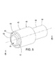
[0031]シール部材52は、ステム通路24に挿入される内部スカート42の内側端部56の近くに配置されている。シール部材52と内部スカート42との間の頸部53は、シール部材52がプローブシール40の中心線に向かって内側にかつステム通路24を形成する壁22から離れるよう、傾斜するおよび/または湾曲することを可能にする。図5および図6において明示されるように、シール部材52は外部スカート44の外側に延在する。シール部材52を外部スカート44の外側に配置し、かつ、シール部材52を内側に向かって傾斜させることによって、組み立ての際、内部スカート42をステム通路24に挿入しやすくなり、また、ステム通路24によるシール部材52および内部スカート42への損傷を最小限に抑える。センサプローブ60がプローブシール40を通ってプロセシングチャンバ12に挿入される時、センサプローブ60は通路24の壁22に向かって外側にシール部材52を押す。センサプローブ60の動きに応じてセンサプローブ60とステム通路24の壁22との間に圧縮性の液密な封止が形成される。
[0031] The
[0032]図6において明示される好適な実施形態では、シール部材52は略円形または略楕円形の形状を有している。センサプローブ60とステム壁22との間の封止を有効化するため、シール部材52の厚さは内部スカート壁の厚さよりも大きいことが望ましい。これにより、センサプローブ60をプローブシール通路24に挿通することによって、シール部材52は内部スカート42の壁50からの干渉なしにセンサプローブ60に封止可能に係合する。また、センサプローブ60に応じたシール部材52の湾曲を容易にするため、頸部53の厚さはスカートの厚さよりも小さいことが望ましい。
[0032] In the preferred embodiment shown in FIG. 6, the
[0033]外部スカート44は内部スカート42から離間して配置され、そのため内部スカート42と外部スカート44との間にスカート溝43が形成されている。スカート溝43は、内部スカート42がステム通路24に押し込まれる時にステム20のテーパ付きフランジ32を受け入れるように構成されている。可撓性高分子材料は、外部スカート44が湾曲してテーパ付きフランジ32を収容することを可能にする。プローブシール40は、ケーブルタイ58などを使って、ステム20に着脱可能に取り付けることができる。また、ケーブルタイ58は、プローブシール40とステムフランジ32との間からプロセシングチャンバ12の流体が漏れ出すのを防ぐ役割も果たす。
[0033] The
[0034]本発明を使用するため、プローブシール40の内側端部56をステム通路24に挿入することによって、プローブシール40がステム20に着脱可能に取り付けられる。外部スカート44の外側に配置され、プローブシールの中心に向かって内側に傾斜するシール部材52は、組立ての際、内部スカート42をステム通路24に挿入しやすくし、また、ステム通路24によるシール部材52および内部スカート42への損傷を最小限に抑える。内部スカート42の外部壁面48は、ステム通路24の内壁22に摺動可能に係合する。内部壁面50は、センサプローブ60を受け入れるように構成されたシール通路46を形成している。
[0034] To use the present invention, the
[0035]内部スカート42がステム通路に挿入される時、内部スカート42と外部スカート44との間に形成されるスカート溝43がステム20のテーパ付きフランジ32を受け入れる。可撓性高分子材料は、外部スカート44が湾曲してテーパ付きフランジ32を収容することを可能にする。外部スカート44を、ひいてはプローブシール40を、ステム20に着脱可能に取り付けるため、溝34に嵌合するように構成されたケーブルタイ58を使用してもよい。
[0035] When the
[0036]プローブシール40がステム20に取り付けられると、センサアセンブリ13の雌ユニット62を内部スカート42の外側端部54に挿入することができる。雌ユニット62をプローブシール40に着脱可能に取り付けるためにケーブルタイ67を使用してもよい。フランジ74を使って、センサアセンブリ13の雄端部70を雌端部62に挿入することができる。雌端部62および雄端部70は、それぞれ雌ラッチ部材64および雄ラッチ部材71を利用して、互いに着脱可能に取り付けられることができる。
[0036] Once the
[0037]雌ユニット62が雄ユニット70に取り付けられた後、当初はスリーブ76に収容されているセンサプローブ60は、シール通路およびステム通路、さらにチャンバ12に挿通されることができる。センサプローブ60は、図3に示されているようにスリーブ76を押して折りたたむことによってスリーブ76の内部から押し出される。
[0037] After the
[0038]プローブシール40をシール通路46に挿入する前は、シール部材52はプローブシール40の中心線に向かって内側にかつステム通路24を形成する壁22から離れるよう、傾斜しておよび/または湾曲している。センサプローブ60がプローブシール40を通ってプロセシングチャンバ12に挿入される時、センサプローブ60はシール部材52に係合し、通路24の壁22に向かって外側にシール部材52を押す。センサプローブ60の動きによって、センサプローブ60とステム通路24の壁22との間に圧縮性の液密な封止が形成される。センサプローブ60とステム壁22との間を封止しやすくするため、シール部材52の厚さは内部スカート壁の厚さよりも大きいことが望ましい。これにより、センサプローブ60をプローブシール通路24に挿通することにより、シール部材52は内部スカート42の壁50からの干渉なしにセンサプローブ60に封止可能に係合する。
[0038] Prior to inserting the
[0039]プローブシール40がなければ、プロセシングチャンバ12の流体はステム通路24とセンサプローブ60を囲むスリーブとに侵入し、溜まる可能性があることが理解されよう。同様に、プローブシール40なしにセンサアセンブリ13が分解されるかセンサプローブが引き抜かれるかした場合、溜まった流体はマニホールドおよび/またはプローブアセンブリから漏れ出す可能性があり、および/またはプローブスリーブの中の流体は使用が困難になる場合もある。よって、本発明によれば、プロセシングチャンバの流体がプローブシール40を越えて漏れ出すのを防止するためにセンサポート16とセンサプローブ60との間に確実な封止を形成するプローブシール40が提供される。
[0039] It will be appreciated that without the
[0040]本開示は発明の説明を目的とするものであり、発明の限定を目的とするものではない。本開示は当業者に多くの変形形態および代替形態を示唆するであろうが、それらはすべて本発明の範囲および添付の特許請求の範囲に含まれるものである。当業者は本明細書に記載された実施形態の均等物を認識するだろうが、そのような均等物も本発明の範囲および添付の特許請求の範囲に含まれることが意図される。 [0040] This disclosure is intended to illustrate the invention and is not intended to limit the invention. This disclosure will suggest many variations and alternatives to one of ordinary skill in the art, all of which are within the scope of the present invention and the appended claims. Those skilled in the art will recognize equivalents to the embodiments described herein, and such equivalents are intended to be included within the scope of the present invention and the appended claims.
10…処理システム、12…プロセシングチャンバ、13…センサアセンブリ、14…センサマニホールド、16,18,19…ポート、20…ステム、22…ステム壁、24…ステム通路、26…内側開口部、28…外側開口部、30,32…フランジ、34…溝、40…プローブシール、42…内部スカート、43…スカート溝、44…外部スカート、46…シール通路、52…シール部材、53…頸部、54…外側端部、56…内側端部、58…ケーブルタイ、60…センサプローブ、62…雌ユニット、64…雌ラッチ部材、67…ケーブルタイ、70…雄ユニット、71…雄ラッチ部材、74…フランジ、76…スリーブ。
DESCRIPTION OF
Claims (12)
前記チャンバ内の状態を測定するためのセンサプローブを有するセンサアセンブリと、
前記チャンバに配置されており、前記センサプローブを受け入れかつ前記センサプローブが前記チャンバ内部に進入できるようにする少なくとも1つのポートであって、該ポートが前記チャンバから外側に突出するステムを備え、前記ステムがフランジと、内側開口部および外側開口部の間に配置されておりかつ前記チャンバ内部と流体連通しているステム通路を形成する内壁とを備える、少なくとも1つのポートと、
前記ポートと前記センサプローブとの間に封止を形成し、前記チャンバ内の流体がこれを越えて漏れ出すのを防止するプローブシールであって、該プローブシールが互いに離間して配置される内部スカートおよび外部スカートを備え、前記プローブシールが前記ステムに取り付けられる時に前記センサプローブを受け入れかつ前記センサプローブが前記チャンバ内部に進入できるようにするシール通路を形成する壁を前記内部スカートが有する、プローブシールと
を備えている生物学的処理システムであって、
前記内部スカートは漏れ止め封止状態を形成するために前記センサプローブおよび前記ステム通路に対して封止可能に押し付けられるシール部材を有し、
前記内部スカートおよび前記外部スカートは、前記内部スカートが前記ステム通路に挿入される時に前記ステムの前記フランジを受け入れるように構成されているスカート溝を形成する、生物学的処理システム。 A chamber having an interior for receiving and processing fluid;
A sensor assembly having a sensor probe for measuring a condition in the chamber;
At least one port disposed in the chamber for receiving the sensor probe and allowing the sensor probe to enter the interior of the chamber, the port including a stem protruding outward from the chamber; At least one port comprising a stem and a flange and an inner wall disposed between the inner and outer openings and forming a stem passage in fluid communication with the interior of the chamber;
A probe seal that forms a seal between the port and the sensor probe and prevents fluid in the chamber from leaking beyond the interior, the probe seals being spaced apart from each other A probe comprising a skirt and an outer skirt, the inner skirt having a wall that receives the sensor probe and allows the sensor probe to enter the interior of the chamber when the probe seal is attached to the stem A biological treatment system comprising a seal,
The inner skirt has a seal member that is sealably pressed against the sensor probe and the stem passage to form a leaktight seal;
The biological treatment system, wherein the inner skirt and the outer skirt form a skirt groove configured to receive the flange of the stem when the inner skirt is inserted into the stem passage.
前記プローブシールと前記ステムとを共に着脱可能に取り付けるケーブルタイがあり、
前記プローブシールが、前記内部スカートが前記ステム通路に挿入される時に前記外部スカートがテーパ付きの前記フランジに柔軟に係合できるように構成された可撓性高分子材料からなり、前記外部スカートが前記ケーブルタイによって前記ステム溝に取り付けられるよう配置されている、請求項1に記載の生物学的処理システム。 The flange of the stem has a tapered shape, the stem further comprising an annular flange disposed between the chamber and the tapered flange, between the annular flange and the tapered flange. Stem groove is formed in
There is a cable tie for detachably attaching the probe seal and the stem together,
The probe seal is made of a flexible polymeric material configured to allow the outer skirt to flexibly engage the tapered flange when the inner skirt is inserted into the stem passage; The biological treatment system of claim 1, wherein the biological treatment system is arranged to be attached to the stem groove by the cable tie.
前記流体を包含するチャンバに流体連通している少なくとも1つのポートであって、該ポートが前記チャンバから外側に突出するステムを備え、前記ステムがフランジと、内側開口部および外側開口部の間に配置されておりかつ前記チャンバ内部と流体連通しているステム通路を形成する内壁とを備える、少なくとも1つのポートと、
互いに離間して配置される内部スカートと外部スカートとを含んでおり、前記ポートと前記センサプローブとの間に封止を形成するプローブシールであって、プロセシングチャンバ内の流体が該プローブシールを越えて漏れ出すのを防止する、プローブシールと
を備え、
前記内部スカートが前記チャンバと流体連通しているシール通路を形成する壁を備え、前記内部スカートが、前記プローブシールが前記ステムに取り付けられる時に前記ステム通路に進入するように配置される内部端を備え、
前記内部スカートが、前記センサプローブを前記シール通路に挿入することにより漏れ止め封止状態を形成するために前記センサプローブおよび前記ステム通路に対して封止可能に押し付けられる、前記内部端の近くに配置されたシール部材を有し、
前記内部スカートが前記ステム通路に挿入される時に前記ステムの前記フランジを受け入れるように構成されたスカート溝を前記内部スカートおよび前記外部スカートが形成している、封止システム。 A sealing system for preventing leakage of the fluid from a chamber containing the fluid when a sensor probe for measuring the state of the fluid in the chamber is inserted into the chamber;
At least one port in fluid communication with the chamber containing the fluid, the port comprising a stem projecting outward from the chamber, the stem between the flange and the inner and outer openings; At least one port comprising: an inner wall disposed and forming a stem passage in fluid communication with the chamber interior;
A probe seal including an inner skirt and an outer skirt spaced apart from each other, and forming a seal between the port and the sensor probe, wherein fluid in the processing chamber exceeds the probe seal With a probe seal that prevents leakage
The inner skirt comprising a wall defining a seal passage in fluid communication with the chamber, the inner skirt having an inner end disposed to enter the stem passage when the probe seal is attached to the stem; Prepared,
Near the inner end, the inner skirt is sealably pressed against the sensor probe and the stem passage to form a leaktight seal by inserting the sensor probe into the seal passage. Having a sealing member disposed;
The sealing system, wherein the inner skirt and the outer skirt form a skirt groove configured to receive the flange of the stem when the inner skirt is inserted into the stem passage.
前記プローブシールと前記ステムとを共に着脱可能に取り付けるケーブルタイがあり、
前記プローブシールが、テーパ付きの前記フランジが前記スカート溝に挿入される時に前記外部スカートがテーパ付きの前記フランジに柔軟に係合できるように構成された可撓性高分子材料からなり、前記外部スカートが前記ケーブルタイによって前記ステム溝に取り付けられるよう配置されている、請求項7に記載の封止システム。 The flange of the stem has a tapered shape, and the stem further comprises an annular flange disposed between the chamber and the tapered flange, the annular flange and the tapered flange A stem groove is formed between them,
There is a cable tie for detachably attaching the probe seal and the stem together,
The probe seal is made of a flexible polymeric material configured to allow the outer skirt to flexibly engage the tapered flange when the tapered flange is inserted into the skirt groove; The sealing system of claim 7, wherein a skirt is arranged to be attached to the stem groove by the cable tie.
Applications Claiming Priority (2)
| Application Number | Priority Date | Filing Date | Title |
|---|---|---|---|
| US13/949,953 US9410626B2 (en) | 2013-07-24 | 2013-07-24 | Sensor probe seal |
| US13/949,953 | 2013-07-24 |
Publications (2)
| Publication Number | Publication Date |
|---|---|
| JP2015037399A JP2015037399A (en) | 2015-02-26 |
| JP5850376B2 true JP5850376B2 (en) | 2016-02-03 |
Family
ID=51352388
Family Applications (1)
| Application Number | Title | Priority Date | Filing Date |
|---|---|---|---|
| JP2014147806A Active JP5850376B2 (en) | 2013-07-24 | 2014-07-18 | Sensor probe seal |
Country Status (6)
| Country | Link |
|---|---|
| US (1) | US9410626B2 (en) |
| EP (1) | EP2829598B1 (en) |
| JP (1) | JP5850376B2 (en) |
| CN (1) | CN104344841B (en) |
| CA (1) | CA2857219A1 (en) |
| SG (1) | SG10201404206PA (en) |
Families Citing this family (19)
| Publication number | Priority date | Publication date | Assignee | Title |
|---|---|---|---|---|
| USD753801S1 (en) * | 2014-08-11 | 2016-04-12 | Klinger Ltd. | Seal |
| DE102015110893B3 (en) | 2015-07-06 | 2016-03-24 | Sartorius Stedim Biotech Gmbh | A method of measuring a plurality of state parameters of a fluid contained in a container |
| DE102015110894B3 (en) | 2015-07-06 | 2016-09-01 | Sartorius Stedim Biotech Gmbh | A method of measuring a plurality of state parameters of a fluid contained in a container |
| US11613724B2 (en) * | 2015-12-10 | 2023-03-28 | Rosemount Inc. | Single-use bioreactor sensor interface |
| DE102016006916B4 (en) * | 2016-06-06 | 2020-06-04 | Sartorius Stedim Biotech Gmbh | Probe holder and method for placing a probe |
| US20180057784A1 (en) | 2016-08-27 | 2018-03-01 | 3D Biotek, Llc | Bioreactor |
| CN107868756A (en) * | 2016-09-28 | 2018-04-03 | 罗斯蒙特分析公司 | Disposable bioreactor sensor interface |
| US10836990B2 (en) | 2016-12-23 | 2020-11-17 | Cyberoptics Corporation | Sensor interface for single-use containers |
| US10584309B2 (en) | 2017-02-06 | 2020-03-10 | Rosemount Inc. | Pressure transducer for single-use containers |
| EP3460037B1 (en) | 2017-09-22 | 2022-03-23 | Sartorius Stedim Biotech GmbH | A device having multiple sterile fluid paths integrated onto a disposable container |
| CN107830951A (en) * | 2017-11-30 | 2018-03-23 | 广东诺能泰自动化技术有限公司 | A kind of battery type digital display manometer |
| DE102018108325B4 (en) * | 2018-04-09 | 2020-07-09 | Schott Ag | Sensor receptacle for a bioreactor and bioreactor with sensor receptacle and process for the propagation or cultivation of biological material |
| EP3781667A1 (en) * | 2018-04-20 | 2021-02-24 | Global Life Sciences Solutions USA LLC | Multiport plate for a bioprocess bag |
| US20210063331A1 (en) * | 2019-08-26 | 2021-03-04 | Stress Engineering Services, Inc. | Dilatometer |
| US11371902B2 (en) | 2019-12-27 | 2022-06-28 | Rosemount Inc. | Process venting feature for use in sensor applications with a process fluid barrier |
| DE102020107763A1 (en) * | 2020-03-20 | 2021-09-23 | Endress+Hauser SE+Co. KG | Sensor attachment for disposable containers |
| DE102020110349B4 (en) * | 2020-04-15 | 2022-01-20 | Mettler-Toledo Gmbh | Sensor mount for using a conventional sensor with a single-use bioreactor while preserving the sterility of the single-use bioreactor |
| WO2023110682A2 (en) * | 2021-12-15 | 2023-06-22 | Norgren LLC | Bioprocessing system and associated sensor manifold |
| US12092484B1 (en) * | 2023-06-21 | 2024-09-17 | Peak Plastics, LLC | Tank and tank probe assembly and method of making same |
Family Cites Families (12)
| Publication number | Priority date | Publication date | Assignee | Title |
|---|---|---|---|---|
| DE9018152U1 (en) | 1989-10-21 | 1996-10-17 | Erlus Baustoffwerke AG, 84088 Neufahrn | Smoke pipe of a chimney made up of several pipe sections |
| JPH0942550A (en) | 1995-07-25 | 1997-02-14 | Hitachi Metals Ltd | Tube fitting |
| EP1778828B1 (en) | 2004-08-16 | 2012-12-19 | Sartorius Stedim Switzerland AG | Bioreactor |
| DE102006001623B4 (en) | 2006-01-11 | 2009-05-07 | Sartorius Stedim Biotech Gmbh | Container and method for mixing media |
| EP1887348B1 (en) * | 2006-06-23 | 2012-12-19 | Mettler-Toledo AG | Immersion pipe for measuring probe |
| US8708376B2 (en) | 2008-10-10 | 2014-04-29 | Deka Products Limited Partnership | Medium connector |
| DE102008060773A1 (en) | 2008-12-05 | 2010-06-10 | Sartorius Stedim Biotech Gmbh | Closure for a container |
| DE102009050448A1 (en) | 2009-06-19 | 2011-12-08 | Sartorius Stedim Biotech Gmbh | A sensor device comprising an optical sensor, a container and a compartmentalizing means |
| DE102009052266B4 (en) * | 2009-11-06 | 2015-05-28 | Eppendorf Ag | Sensor Adapter, Sensor Adapter Manufacturing Process, How to Insert a Sensor into This Sensor Adapter |
| JP2013533171A (en) * | 2010-04-19 | 2013-08-22 | エイティーエムアイ ビーブイビーエイ | Drain connector for fluid handling and storage vessels |
| US20130084030A1 (en) | 2011-10-03 | 2013-04-04 | Hyclone Laboratories, Inc. | Disposable plug and sensor fittings for bioreactor bags |
| WO2013063550A1 (en) | 2011-10-28 | 2013-05-02 | Xcellerex, Inc. | Probe assembly |
-
2013
- 2013-07-24 US US13/949,953 patent/US9410626B2/en active Active
-
2014
- 2014-07-18 EP EP14177659.1A patent/EP2829598B1/en active Active
- 2014-07-18 JP JP2014147806A patent/JP5850376B2/en active Active
- 2014-07-18 SG SG10201404206PA patent/SG10201404206PA/en unknown
- 2014-07-18 CA CA2857219A patent/CA2857219A1/en not_active Abandoned
- 2014-07-24 CN CN201410466198.2A patent/CN104344841B/en active Active
Also Published As
| Publication number | Publication date |
|---|---|
| EP2829598A3 (en) | 2015-02-18 |
| US20150030514A1 (en) | 2015-01-29 |
| CA2857219A1 (en) | 2015-01-24 |
| EP2829598A2 (en) | 2015-01-28 |
| SG10201404206PA (en) | 2015-02-27 |
| CN104344841B (en) | 2017-05-03 |
| EP2829598B1 (en) | 2018-09-05 |
| JP2015037399A (en) | 2015-02-26 |
| US9410626B2 (en) | 2016-08-09 |
| CN104344841A (en) | 2015-02-11 |
Similar Documents
| Publication | Publication Date | Title |
|---|---|---|
| JP5850376B2 (en) | Sensor probe seal | |
| US10946183B2 (en) | Aseptic connector | |
| US10247342B2 (en) | Connector assemblies, fluid systems including connector assemblies, and procedures for making fluid connections | |
| JP5680270B2 (en) | Fluid transfer device | |
| DK2313049T3 (en) | fluid transfer device | |
| KR20120091437A (en) | Configurable port fitment, kit, and related methods | |
| US7614607B2 (en) | Drain connector for substance processing receptacle | |
| US8505396B2 (en) | Fluid transfer device | |
| EP2475973B1 (en) | A sampling device | |
| US20100301060A1 (en) | Connection of an accessory to a vessel | |
| US9011407B2 (en) | Pre-evacuatable or pre-evacuated container for medical purposes | |
| US20120260608A1 (en) | Drain connector for substance processing receptacle | |
| KR20170070127A (en) | Aseptic filter vent valve and port for integrity testing | |
| US11633328B2 (en) | Bag containing a biopharmaceutical product and probe holder port for such a product | |
| US7806009B2 (en) | Immersion tube for a measuring probe | |
| WO2014057856A1 (en) | Plug, medical module and medical system | |
| US20140001392A1 (en) | Fluid Transfer Device | |
| US11173635B2 (en) | Fluid transfer assembly, a fluid transfer system, and a related method | |
| US20240110142A1 (en) | Aseptic cell culture system and methods of use | |
| US20210129152A1 (en) | Connector for Flexible Tubing | |
| JP2021503920A (en) | Methods and equipment for aseptic dry transfer |
Legal Events
| Date | Code | Title | Description |
|---|---|---|---|
| A977 | Report on retrieval |
Free format text: JAPANESE INTERMEDIATE CODE: A971007 Effective date: 20150604 |
|
| A131 | Notification of reasons for refusal |
Free format text: JAPANESE INTERMEDIATE CODE: A131 Effective date: 20150623 |
|
| A521 | Request for written amendment filed |
Free format text: JAPANESE INTERMEDIATE CODE: A523 Effective date: 20150731 |
|
| TRDD | Decision of grant or rejection written | ||
| A01 | Written decision to grant a patent or to grant a registration (utility model) |
Free format text: JAPANESE INTERMEDIATE CODE: A01 Effective date: 20151104 |
|
| A61 | First payment of annual fees (during grant procedure) |
Free format text: JAPANESE INTERMEDIATE CODE: A61 Effective date: 20151120 |
|
| R150 | Certificate of patent or registration of utility model |
Ref document number: 5850376 Country of ref document: JP Free format text: JAPANESE INTERMEDIATE CODE: R150 |
|
| R250 | Receipt of annual fees |
Free format text: JAPANESE INTERMEDIATE CODE: R250 |
|
| R250 | Receipt of annual fees |
Free format text: JAPANESE INTERMEDIATE CODE: R250 |
|
| R250 | Receipt of annual fees |
Free format text: JAPANESE INTERMEDIATE CODE: R250 |
|
| R250 | Receipt of annual fees |
Free format text: JAPANESE INTERMEDIATE CODE: R250 |
|
| R250 | Receipt of annual fees |
Free format text: JAPANESE INTERMEDIATE CODE: R250 |
|
| R250 | Receipt of annual fees |
Free format text: JAPANESE INTERMEDIATE CODE: R250 |
|
| S111 | Request for change of ownership or part of ownership |
Free format text: JAPANESE INTERMEDIATE CODE: R313113 |
|
| R350 | Written notification of registration of transfer |
Free format text: JAPANESE INTERMEDIATE CODE: R350 |