JP5846506B2 - Tissue stabilization device and method with self-extensible head link assembly - Google Patents
Tissue stabilization device and method with self-extensible head link assembly Download PDFInfo
- Publication number
- JP5846506B2 JP5846506B2 JP2013521835A JP2013521835A JP5846506B2 JP 5846506 B2 JP5846506 B2 JP 5846506B2 JP 2013521835 A JP2013521835 A JP 2013521835A JP 2013521835 A JP2013521835 A JP 2013521835A JP 5846506 B2 JP5846506 B2 JP 5846506B2
- Authority
- JP
- Japan
- Prior art keywords
- collet
- tube
- tissue stabilizer
- arm
- link assembly
- Prior art date
- Legal status (The legal status is an assumption and is not a legal conclusion. Google has not performed a legal analysis and makes no representation as to the accuracy of the status listed.)
- Active
Links
- 238000000034 method Methods 0.000 title description 12
- 230000006641 stabilisation Effects 0.000 title description 4
- 238000011105 stabilization Methods 0.000 title description 4
- 239000003381 stabilizer Substances 0.000 claims description 77
- 230000007246 mechanism Effects 0.000 claims description 37
- 230000007480 spreading Effects 0.000 claims description 21
- 238000003892 spreading Methods 0.000 claims description 21
- 239000000463 material Substances 0.000 claims description 14
- 230000007704 transition Effects 0.000 claims description 9
- 229920003023 plastic Polymers 0.000 claims description 7
- 239000004033 plastic Substances 0.000 claims description 7
- 239000002184 metal Substances 0.000 claims description 4
- 230000004044 response Effects 0.000 claims description 4
- 230000007423 decrease Effects 0.000 claims description 2
- 210000003000 inclusion body Anatomy 0.000 claims description 2
- 229920000642 polymer Polymers 0.000 claims description 2
- 238000005452 bending Methods 0.000 claims 3
- 230000008520 organization Effects 0.000 claims 2
- 210000001519 tissue Anatomy 0.000 description 68
- 230000006870 function Effects 0.000 description 28
- 238000001356 surgical procedure Methods 0.000 description 11
- 210000004351 coronary vessel Anatomy 0.000 description 6
- 210000000056 organ Anatomy 0.000 description 4
- 229910000831 Steel Inorganic materials 0.000 description 3
- 238000010276 construction Methods 0.000 description 3
- 230000000087 stabilizing effect Effects 0.000 description 3
- 239000010959 steel Substances 0.000 description 3
- 241000238413 Octopus Species 0.000 description 2
- 230000003872 anastomosis Effects 0.000 description 2
- 230000000747 cardiac effect Effects 0.000 description 2
- 230000002612 cardiopulmonary effect Effects 0.000 description 2
- 230000006872 improvement Effects 0.000 description 2
- 238000004519 manufacturing process Methods 0.000 description 2
- 238000000465 moulding Methods 0.000 description 2
- 230000036961 partial effect Effects 0.000 description 2
- 230000002093 peripheral effect Effects 0.000 description 2
- 229920000915 polyvinyl chloride Polymers 0.000 description 2
- 239000004800 polyvinyl chloride Substances 0.000 description 2
- 230000001681 protective effect Effects 0.000 description 2
- 230000000717 retained effect Effects 0.000 description 2
- 210000003371 toe Anatomy 0.000 description 2
- 208000010496 Heart Arrest Diseases 0.000 description 1
- 230000003466 anti-cipated effect Effects 0.000 description 1
- 210000001367 artery Anatomy 0.000 description 1
- QVGXLLKOCUKJST-UHFFFAOYSA-N atomic oxygen Chemical compound [O] QVGXLLKOCUKJST-UHFFFAOYSA-N 0.000 description 1
- 238000010009 beating Methods 0.000 description 1
- 230000009286 beneficial effect Effects 0.000 description 1
- 230000008901 benefit Effects 0.000 description 1
- 239000008280 blood Substances 0.000 description 1
- 210000004369 blood Anatomy 0.000 description 1
- 210000004204 blood vessel Anatomy 0.000 description 1
- 239000000919 ceramic Substances 0.000 description 1
- 230000008859 change Effects 0.000 description 1
- 230000006835 compression Effects 0.000 description 1
- 238000007906 compression Methods 0.000 description 1
- 230000008878 coupling Effects 0.000 description 1
- 238000010168 coupling process Methods 0.000 description 1
- 238000005859 coupling reaction Methods 0.000 description 1
- 230000003247 decreasing effect Effects 0.000 description 1
- 238000005538 encapsulation Methods 0.000 description 1
- 210000005003 heart tissue Anatomy 0.000 description 1
- 238000007373 indentation Methods 0.000 description 1
- 238000005304 joining Methods 0.000 description 1
- 230000000670 limiting effect Effects 0.000 description 1
- 230000000873 masking effect Effects 0.000 description 1
- 238000002324 minimally invasive surgery Methods 0.000 description 1
- 229910052760 oxygen Inorganic materials 0.000 description 1
- 239000001301 oxygen Substances 0.000 description 1
- 230000000149 penetrating effect Effects 0.000 description 1
- 229920002635 polyurethane Polymers 0.000 description 1
- 239000004814 polyurethane Substances 0.000 description 1
- 230000002787 reinforcement Effects 0.000 description 1
- 230000002441 reversible effect Effects 0.000 description 1
- 210000004872 soft tissue Anatomy 0.000 description 1
- 239000007787 solid Substances 0.000 description 1
- 229910001220 stainless steel Inorganic materials 0.000 description 1
- 239000010935 stainless steel Substances 0.000 description 1
- 210000001562 sternum Anatomy 0.000 description 1
- 238000012800 visualization Methods 0.000 description 1
- 238000003466 welding Methods 0.000 description 1
Images


Classifications
-
- A—HUMAN NECESSITIES
- A61—MEDICAL OR VETERINARY SCIENCE; HYGIENE
- A61B—DIAGNOSIS; SURGERY; IDENTIFICATION
- A61B17/00—Surgical instruments, devices or methods, e.g. tourniquets
- A61B17/02—Surgical instruments, devices or methods, e.g. tourniquets for holding wounds open; Tractors
- A61B17/0206—Surgical instruments, devices or methods, e.g. tourniquets for holding wounds open; Tractors with antagonistic arms as supports for retractor elements
-
- A—HUMAN NECESSITIES
- A61—MEDICAL OR VETERINARY SCIENCE; HYGIENE
- A61B—DIAGNOSIS; SURGERY; IDENTIFICATION
- A61B17/00—Surgical instruments, devices or methods, e.g. tourniquets
- A61B17/02—Surgical instruments, devices or methods, e.g. tourniquets for holding wounds open; Tractors
- A61B2017/0237—Surgical instruments, devices or methods, e.g. tourniquets for holding wounds open; Tractors for heart surgery
- A61B2017/0243—Surgical instruments, devices or methods, e.g. tourniquets for holding wounds open; Tractors for heart surgery for immobilizing local areas of the heart, e.g. while it beats
-
- A—HUMAN NECESSITIES
- A61—MEDICAL OR VETERINARY SCIENCE; HYGIENE
- A61B—DIAGNOSIS; SURGERY; IDENTIFICATION
- A61B17/00—Surgical instruments, devices or methods, e.g. tourniquets
- A61B17/28—Surgical forceps
- A61B17/29—Forceps for use in minimally invasive surgery
- A61B2017/2901—Details of shaft
- A61B2017/2905—Details of shaft flexible
-
- A—HUMAN NECESSITIES
- A61—MEDICAL OR VETERINARY SCIENCE; HYGIENE
- A61B—DIAGNOSIS; SURGERY; IDENTIFICATION
- A61B17/00—Surgical instruments, devices or methods, e.g. tourniquets
- A61B17/30—Surgical pincettes without pivotal connections
- A61B2017/306—Surgical pincettes without pivotal connections holding by means of suction
- A61B2017/308—Surgical pincettes without pivotal connections holding by means of suction with suction cups
-
- A—HUMAN NECESSITIES
- A61—MEDICAL OR VETERINARY SCIENCE; HYGIENE
- A61B—DIAGNOSIS; SURGERY; IDENTIFICATION
- A61B90/00—Instruments, implements or accessories specially adapted for surgery or diagnosis and not covered by any of the groups A61B1/00 - A61B50/00, e.g. for luxation treatment or for protecting wound edges
- A61B90/50—Supports for surgical instruments, e.g. articulated arms
- A61B90/57—Accessory clamps
- A61B2090/571—Accessory clamps for clamping a support arm to a bed or other supports
Description
本開示は、概略的には、体組織および臓器の外科手術に関する。より詳しくは、本開示は、臓器の組織を係合するため、例えば、臓器を所望の向きに位置決めするため、または、心臓壁などの動きの影響を受ける組織の局所的領域を一時的に固定するための機器および方法に関し、外科的処置をその組織の局所領域で行うことを可能にする。 The present disclosure relates generally to surgical operations on body tissues and organs. More particularly, the present disclosure temporarily fixes local regions of tissue to engage organ tissue, for example, to position the organ in a desired orientation, or to be affected by motion, such as the heart wall. With regard to instruments and methods for doing so, it allows surgical procedures to be performed on local areas of the tissue.
合衆国ではおよそ300,000人の患者が毎年、冠状動脈バイパス移植手術を受ける。従来の冠状動脈バイパス移植手術では、処置の間に心臓の鼓動を停止する必要がある。人工心肺は、心臓の停止中に、患者の血液を圧送し、酸素を加えるために使われる。より最近では、オフポンプ手術、または心拍動下手術が、従来の人工心肺処置の魅力的な代替案となっている。 Approximately 300,000 patients in the United States undergo coronary artery bypass graft surgery each year. Conventional coronary artery bypass graft surgery requires that the heart beat be stopped during the procedure. Cardiopulmonary bypass is used to pump the patient's blood and add oxygen during cardiac arrest. More recently, off-pump or heart beat surgery has become an attractive alternative to conventional cardiopulmonary procedures.
心拍動下冠状動脈バイパス移植手術における課題の一つは、鼓動している心臓を縫合または縫うことが困難になることである。外科医は、「安定化」システムを使用して、心臓を安定させ続けなければならない。通常は、安定化システムは、心臓ポジショナーと組織スタビライザから成る。心臓ポジショナーは、閉塞動脈への最良のアクセスをもたらす位置に心臓を誘導し、保持する。組織スタビライザは、外科医が移植血管を、1つまたは複数の冠状動脈における閉塞の周りに取り付ける間、心臓の小領域を静止状態に保持し、安定した縫合部位の妨げのない視界を外科医にもたらす。 One challenge in coronary artery bypass graft surgery under heart beat is that it becomes difficult to suture or sew the beating heart. The surgeon must continue to stabilize the heart using a “stabilization” system. Usually, the stabilization system consists of a cardiac positioner and a tissue stabilizer. The cardiac positioner guides and holds the heart in a position that provides the best access to the occluded artery. The tissue stabilizer keeps a small area of the heart stationary while the surgeon attaches a graft vessel around an occlusion in one or more coronary arteries, providing the surgeon with an unobstructed view of a stable suture site.
組織スタビライザの中には、簡単な機械的フォークを使用して圧力型スタビライザを通じて吻合部位の近傍に心外膜組織を固定するよう設計されたものがある。そのような機器は、フォークを心臓表面に押し下げることによって心臓を安定化させる。典型的に、フォークは細長いアームに取り付けられ、一方、患者の肋骨を離れた状態に保持することによって手術用の窓部を形成するリトラクタに、この細長いアームが取り付けられる。場合によっては、リトラクタに対してアームを斜めに移動することはタレットにより実現され、所望の回転位置にクランプすることができる。通常、リトラクタに対してアームを長手方向に移動することも可能であり、および通常は、アームをタレットにクランプし、アームに対してフォークを固定することを可能にするよう、クランプ機構が提供される。例示的な圧力組織安定化機器は、特許文献1および特許文献2に開示されている。 Some tissue stabilizers are designed to fix epicardial tissue in the vicinity of the anastomosis site through a pressure stabilizer using a simple mechanical fork. Such devices stabilize the heart by pushing the fork down to the heart surface. Typically, the fork is attached to an elongate arm, while the elongate arm is attached to a retractor that forms a surgical window by holding the patient's ribs apart. In some cases, the oblique movement of the arm with respect to the retractor is realized by the turret and can be clamped at the desired rotational position. Usually it is also possible to move the arm longitudinally relative to the retractor, and usually a clamping mechanism is provided to allow the arm to be clamped to the turret and the fork to be fixed relative to the arm. The Exemplary pressure tissue stabilization devices are disclosed in US Pat.
より最近では、吸引ベースの組織スタビライザ、例えばMedtronicOctopus(登録商標)組織スタビライザ(Medtronic社より販売)が幅広く受け入れられており、その遠位端で一対の吸引パドルまたはポッドを担持する比較的長く、可撓性のある関節連結アームを使用する。吸引ポッドは、負の圧力源に流体的に接続される。使用中、典型的には、患者の肋骨を離れた状態に保持することによって手術用の窓部を形成するリトラクタに、アームが固定される。ポッドは吻合部位の反対側に配置され、吸引力が印加されて、心臓の表面を担持して固定する。その後、張力がアームの長手方向に印加され、所望の空間配向にアームを固定し、アームに対してポッドの位置を固定する。そのような機器の例は、特許文献3および特許文献4に記載され、参照によりその両方の全体の内容が本明細書に組み込まれる。吸引型組織スタビライザの他の例は、特許文献5「組織安定化方法および機器(Methods and Devices for Stabilizing Tissue)」に記載され、その全体が参照により本明細書に組み込まれる。これらの機器では、吸引印加ポッドは、概ねY型ヘッドによって担持され、そのようなY型ヘッドは、関節連結アームによって担持されるコレットに、回転自在に結合されたヘッドリンクアセンブリの一部として提供される。これらの構造では、張力要素は、外科医によって操作可能であり、コレットに対してヘッドリンクアセンブリの球状ベースを選択的にクランプする。張力要素を緩めと、ヘッドリンクアセンブリは、コレットと垂直をなす面より上で事実上どの角度(すなわち、ヨー、ピッチ、およびロール)にも回転および/または枢動することができ、一般的に、ポッドアップ(pods−up)、ポッドダウン(pods−down)、およびポッドツーサイド(pods−to−the−side)アプリケーションと呼ばれるものを備えている複数の機器位置を助長する。そのような吸引組織スタビライザの例は、商標名Octopus(登録商標)Evolution(商標)組織スタビライザがMedtronic社から市販されている。 More recently, suction-based tissue stabilizers, such as the Medtronic Octopus® tissue stabilizer (sold by Medtronic), have gained wide acceptance and are relatively long and capable of carrying a pair of suction paddles or pods at their distal ends. Use flexible articulating arms. The suction pod is fluidly connected to a negative pressure source. During use, the arm is typically secured to a retractor that forms a surgical window by holding the patient's ribs apart. The pod is placed on the opposite side of the anastomosis site and a suction force is applied to carry and fix the surface of the heart. Tension is then applied in the longitudinal direction of the arm, fixing the arm in the desired spatial orientation and fixing the position of the pod relative to the arm. Examples of such devices are described in U.S. Patent Nos. 5,099,066 and 5,037,096, the entire contents of both being incorporated herein by reference. Other examples of aspiration-type tissue stabilizers are described in US Pat. No. 5,099,059, “Methods and Devices for Stabilizing Tissue”, which is incorporated herein by reference in its entirety. In these devices, the suction applicator pod is generally carried by a Y-type head, and such Y-type head is provided as part of a head link assembly that is rotatably coupled to a collet carried by an articulating arm. Is done. In these structures, the tension element is operable by the surgeon and selectively clamps the spherical base of the head link assembly against the collet. When the tension element is loosened, the head link assembly can rotate and / or pivot at virtually any angle (ie yaw, pitch, and roll) above the plane perpendicular to the collet, typically Facilitates multiple device locations with what are called pods-up, pods-down, and pods-to-the-side applications. An example of such a suction tissue stabilizer is the trade name Octopus® Evolution ™ tissue stabilizer commercially available from Medtronic.
オフポンプ冠状動脈バイパス移植外科的処置で使用する市販の組織スタビライザは極めて有望であるが、どんな改良も、歓迎される。例えば、組織スタビライザの吸引ポッド間にある心臓の組織をわずかに延伸する能力を外科医は要望し、ヘッドリンクアセンブリを直接、操作することなくポッドを広げることを好む。 Although commercially available tissue stabilizers for use in off-pump coronary artery bypass graft surgical procedures are very promising, any improvements are welcomed. For example, surgeons desire the ability to stretch the heart tissue slightly between the suction pods of the tissue stabilizer and prefer to expand the pods without directly manipulating the head link assembly.
本開示の原理によるいくつかの態様は、細長いアーム、コレット、およびヘッドリンクアセンブリを備えている組織スタビライザに関連する。細長いアームは、遠位端で終端する。コレットは、遠位端に配置される。最後に、ヘッドリンクアセンブリは、コレットに回転自在に結合可能で、チューブと拡げ機構を備えている。チューブは、負の圧力を組織に印加するように構成され、中間部分、第1のアーム、および第2のアームを形成する。第1のアームは、中間部分から伸び、先端で終端する。第2のアームも、中間部分から伸び、先端で終端するが、第1のアームの反対側である(例えば、第1のアームから水平方向に離間配置される)。拡げ機構は、先端の間の水平方向距離を調整するよう構成され、第1および第2の関節連結部材を備えている。各関節連結部材は、脚、および脚から突出するコレットインターフェース本体を備えている。第1の関節連結部材は、雌ヒンジ機能を更に含み、一方、第2の拡がり部材は、雌ヒンジ機能と形状が異なる雄ヒンジ機能を備えている。ヘッドリンクアセンブリの最終構成時に、拡げ機構の脚は、それぞれ、チューブの中間部分の不連続領域に取り付けられ、雄ヒンジ機能は雌ヒンジ機能と枢動可能に結合される。ヘッドリンクアセンブリは、コレットインターフェース本体に印加された圧縮力に応じて、先端の間に第1の水平方向距離を有する初期状態から、先端の間に第2の水平方向距離を有する伸張状態に切り替え可能である。この点に関し、第1の水平方向距離は、第2の水平方向距離未満である。例えば、コレットインターフェース本体がコレット内に挿入され、コレットがしっかり締められると、コレットインターフェース本体は、互いを押し合い、関節連結部材の脚を互いに対して枢動させる。次に、この枢動力はチューブに伝わり、第1および第2のアームを広げさせる。いくつかの実施形態において、チューブはU型であり、中間部分が中間点を有する曲げを規定する。関連した実施形態において、ヒンジ機能は、中間点で互いに結合され、コレットインターフェース本体は、概ね、中間点と整列する。他の実施形態において、ヘッドリンクアセンブリは、ヒンジ機能の所望の関節を可能にする方法で、チューブおよび拡げ機構にオーバーモールドされるポリマー封入体を更に備えている。更に他の実施形態において、チューブは、アームに形成した真空開口部に負の圧力を供給するために対向するアームに沿うかその間に伸びる単一の管腔を形成し、この単一の管腔は、中間部分の厚さを通して形成された単一の吸気口を介して、負の圧力源に流体的に接続される。 Some aspects in accordance with the principles of the present disclosure relate to a tissue stabilizer that includes an elongate arm, a collet, and a head link assembly. The elongate arm terminates at the distal end. The collet is disposed at the distal end. Finally, the head link assembly is rotatably coupled to the collet and includes a tube and an expansion mechanism. The tube is configured to apply a negative pressure to the tissue and forms an intermediate portion, a first arm, and a second arm. The first arm extends from the middle portion and terminates at the tip. The second arm also extends from the middle portion and terminates at the tip, but is opposite the first arm (eg, spaced horizontally from the first arm). The expansion mechanism is configured to adjust the horizontal distance between the distal ends, and includes first and second joint connecting members. Each joint connecting member includes a leg and a collet interface body protruding from the leg. The first joint connecting member further includes a female hinge function, while the second spreading member has a male hinge function that is different in shape from the female hinge function. During final configuration of the head link assembly, the legs of the spreading mechanism are each attached to a discontinuous region in the middle portion of the tube, and the male hinge function is pivotally coupled to the female hinge function. The head link assembly switches from an initial state having a first horizontal distance between the tips to an extended state having a second horizontal distance between the tips in response to a compressive force applied to the collet interface body. Is possible. In this regard, the first horizontal distance is less than the second horizontal distance. For example, when the collet interface body is inserted into the collet and the collet is tightened, the collet interface body presses against each other and pivots the legs of the articulation member relative to each other. This pivotal power is then transmitted to the tube, causing the first and second arms to expand. In some embodiments, the tube is U-shaped and the middle portion defines a bend with a midpoint. In related embodiments, the hinge functions are coupled together at a midpoint, and the collet interface body is generally aligned with the midpoint. In other embodiments, the head link assembly further comprises a polymer enclosure that is overmolded to the tube and expansion mechanism in a manner that allows the desired articulation of the hinge function. In yet other embodiments, the tube forms a single lumen along or extending between opposing arms to provide negative pressure to a vacuum opening formed in the arm, the single lumen Is fluidly connected to a negative pressure source via a single inlet formed through the thickness of the intermediate portion.
本開示の原理による更に他の態様は、細長いアーム、コレット、およびヘッドリンクアセンブリを備えた組織スタビライザに関する。細長いアームは、コレットが配置された遠位端で終端する。ヘッドリンクアセンブリは、コレットに回転自在に結合可能で、チューブと拡げ機構を備えている。チューブは、負の圧力を組織に印加するよう構成され、外面および管腔を規定する。更に、チューブは中間部分を形成し、および中間部分から伸び、それぞれが先端で終端される、対向する第1および第2のアームを形成する。拡げ機構はチューブから離れて形成され、その外面に取り付けられる。拡げ機構は、脚、コレットインターフェース本体、およびヒンジ機能をそれぞれが有する第1および第2の関節連結部材を備えている。拡げ機構をチューブの外面に取り付けるとき、脚は中間部分に取り付けられ、ヒンジ機能は互いに枢動可能に結合され、コレットインターフェース本体は整列する。ヘッドリンクアセンブリは、コレットインターフェース本体に伝えられた圧縮力に応じて、先端の間に第1の水平方向距離を有する初期状態から、先端の間に第2の水平方向距離を有する伸張状態に切り替え可能である。この点に関し、第1の水平方向距離は、第2の水平方向距離未満である。負の圧力を供給するチューブから拡げ機構を離して形成することによって、ヘッドリンクアセンブリは、単純、薄型、堅牢、高信頼性および製造が容易な自動化された拡がり機能を提供する。 Yet another aspect in accordance with the principles of the present disclosure is directed to a tissue stabilizer including an elongated arm, a collet, and a head link assembly. The elongate arm terminates at the distal end where the collet is located. The head link assembly is rotatably coupled to the collet and includes a tube and an expansion mechanism. The tube is configured to apply a negative pressure to the tissue and defines an outer surface and a lumen. Further, the tube forms an intermediate portion and extends from the intermediate portion to form opposing first and second arms, each terminated at the tip. The spreading mechanism is formed away from the tube and attached to its outer surface. The spreading mechanism includes a leg, a collet interface body, and first and second joint connecting members each having a hinge function. When the spreading mechanism is attached to the outer surface of the tube, the legs are attached to the middle portion, the hinge functions are pivotally coupled to each other, and the collet interface body is aligned. The head link assembly switches from an initial state having a first horizontal distance between the tips to an extended state having a second horizontal distance between the tips in response to a compressive force transmitted to the collet interface body. Is possible. In this regard, the first horizontal distance is less than the second horizontal distance. By forming the spreading mechanism away from the tube supplying the negative pressure, the head link assembly provides an automated spreading function that is simple, thin, robust, reliable and easy to manufacture.
本発明の原理による更に他の態様は、組織を安定化する方法に関する。本方法は、組織スタビライザをリトラクタにクランプすることを備えている。組織スタビライザは、細長いアームの遠位端に配置されたコレット、ならびにコレットに回転自在に結合されたヘッドリンクアセンブリを備えている。ヘッドリンクアセンブリは、中間部分を規定するチューブ、および中間部分から伸びる対向する第1および第2のアームを備えている。更に、拡げ機構は、ヘッドリンクアセンブリを備え、脚、および脚から突出するコレットインターフェース本体をそれぞれが有する第1および第2の関節連結部材を備えている。第1の関節連結部材は、雌ヒンジ機能を更に含み、第2の関節連結部材は、雌ヒンジ機能と形状が異なる雄ヒンジ機能を更に備えている。脚は、それぞれ中間部分の不連続領域に取り付けられ、雄ヒンジ機能は、雌ヒンジ機能に枢動可能に結合される。ヘッドリンクアセンブリは、コレットに対して回転および枢動し、初期状態において、組織に対しヘッドリンクアセンブリを位置決めする。ヘッドリンクアセンブリに真空が印加され、第1および第2のアームで吸引力が生成され、組織にアームが固定される。コレットインターフェース本体に圧縮力が印加され、組織の一部を延伸するために初期状態から伸張状態にアームが広げられる。いくつかの実施形態において、組織スタビライザは、アームを通して伸び、コレットに結合された張力要素を更に備えている。関連した実施形態において、コレットインターフェース本体上でコレットをしっかり締めるための張力要素を作動することによって圧縮力がコレットインターフェース本体に印加される。 Yet another aspect in accordance with the principles of the invention relates to a method of stabilizing tissue. The method comprises clamping the tissue stabilizer to a retractor. The tissue stabilizer includes a collet disposed at the distal end of the elongate arm, and a head link assembly rotatably coupled to the collet. The head link assembly includes a tube defining an intermediate portion and opposing first and second arms extending from the intermediate portion. Further, the expansion mechanism includes a head link assembly and includes first and second articulation members each having a leg and a collet interface body protruding from the leg. The first joint connecting member further includes a female hinge function, and the second joint connecting member further includes a male hinge function different in shape from the female hinge function. The legs are each attached to a discontinuous region in the middle portion, and the male hinge function is pivotally coupled to the female hinge function. The head link assembly rotates and pivots with respect to the collet, and initially positions the head link assembly with respect to the tissue. A vacuum is applied to the head link assembly, a suction force is generated by the first and second arms, and the arms are secured to the tissue. A compressive force is applied to the collet interface body, and the arm is expanded from the initial state to the expanded state to stretch a portion of the tissue. In some embodiments, the tissue stabilizer further comprises a tension element extending through the arm and coupled to the collet. In a related embodiment, a compressive force is applied to the collet interface body by actuating a tension element to tighten the collet on the collet interface body.
本開示の原理による、外科的処置の間に心臓などの身体臓器の組織を安定化する際に使用するための組織スタビライザ20の一実施形態を、図1に示す。組織スタビライザ20は、細長いアーム22、コレット24、およびヘッドリンクアセンブリ26を備えている。更に、クランプ28、タレット30、ハンドル32、および/または真空チューブアセンブリ34等の、任意選択部材も、組織スタビライザ20に備えることができる。様々な部材の詳細は、後述する。しかしながら、一般論として、コレット24は細長いアーム22の遠位端に配置される。ヘッドリンクアセンブリ26は、(例えば、真空チューブアセンブリ34を介して)負の圧力を接触した組織に印加するよう構成され、さらに、コレット24に回転自在に結合可能である。この点に関し、ヘッドリンクアセンブリ26は、回動自在かつ枢動(軸回転自在)に、コレット24に対して関節接合することができ、これによりコレット24に対して広範囲にわたる様々な傾きおよび回転位置(例えば、ヨー、ピッチ、およびロールの観点からの動きの自由度)をとることができる。更に、ヘッドリンクアセンブリ26は、「自動」拡がり動作を実現するよう構成され、自動拡がり動作ではヘッドリンクアセンブリ26のアームが、異なる水平方向間隔に自己移行させられる。用語「自動拡がり」および「自動化された拡がり」は、外科医が直接、または物理的にアームを扱うことなく、自然な水平方向間隔から伸張された水平方向間隔に移行するヘッドリンクアセンブリのアームに関する。したがって、ヘッドリンクアセンブリ26は、外科医によって所望されるように空間的に配置することができ、外科的処置の一部として接触した組織を迅速に延伸することができる。
One embodiment of a
図1に反映され、以下に記載された様々な部材22〜34の機能は、異なる構造および/または機構に変更または置き換えることができる。したがって、本開示は、以下に示され記載されるような、細長いアーム22、コレット24、クランプ28、タレット30等に限定されるものではない。より一般的には、本開示による組織スタビライザは、ヘッドリンクアセンブリ26の、作業者が要求される自動化された拡がりを可能にする方法で、ヘッドリンクアセンブリ26を回動自在かつ枢動(軸回転)可能に維持するよう構成されたコレット構造と組み合わせて、以下に記載するようなヘッドリンクアセンブリ26を組み込む。
The functions of the various members 22-34 reflected in FIG. 1 and described below can be altered or replaced with different structures and / or mechanisms. Accordingly, the present disclosure is not limited to the elongated arm 22, the
ヘッドリンクアセンブリ26は、図2Aおよび図2Bにより詳しく示され、負の圧力を供給するチューブ40(図2Aおよび図2Bでは隠れているが、概略を示す)、拡げ機構42、任意選択の封入体44、および任意選択の第1および第2のポッド本体46、48を備えている。ポッド本体46、48は、図のようにチューブ40によって担持され、チューブ40によって規定される1つまたは複数の管腔に流体的に接続される機能を備えている。拡げ機構42は、チューブ40に取り付けられ、外力(例えば、圧縮力)に応じてチューブ40をたわませるよう構成される。封入体44は、提供された場合、以下に記載するように、拡げ機構42の枢動を可能にする方法で、拡げ機構42とチューブ40の間の堅固な接続をより確実にする。
The
チューブ40は図3において簡易化された断面図に示され、ほぼU型の形状を有し、中間部分60、対向する第1および第2のアーム62、64を規定することができる。チューブ40がU形状の実施形態では、比較的均一な半径を有し、中間点または頂点66を規定する曲げを、中間部分60が規定する。第1のアーム62は、中間部分60から伸び、先端68で終端する。第2のアーム64は、同様に、中間部分60から伸び、先端70で終端する。図のように、アーム62、64は、中間部分60から互いに反対側に伸びており、先端68、70は水平方向距離または間隔で互いから水平方向に分かれている。構造によっては、第1および第2のアーム62、64は、互いに、および中間部分60と同一平面状にある。中間部分60に対するアーム62、64の他の形状および/または向きも考えられる。
The
チューブ40は、予想される真空圧力およびたわみ力のもとでチューブ40の構造的な保全性を維持するよう適合された材料で形成される。いくつかの実施形態において、チューブ40は金属(例えば、ステンレス鋼)またはある程度の可鍛性があり、形状記憶特性を有する同様の材料である。形状記憶特性は、チューブ40に、先端68、70の間の自然間隔SNを規定する図3に示す自然の形状を自然にとらせる。たわみ力を受けると、アーム62、64は、(チューブ40を、中間点66等の中間部分60に沿って効果的に枢動して)互いに離れることが可能で、先端68、70の間の水平方向間隔が増す。しかしながら、この外力がなくなると、チューブ40の形状記憶特性は、チューブ40を、自然の水平方向間隔SNを有する初期状態に自己復帰させる。
The
各アーム62、64は、構造によっては、チューブ40の壁厚を貫通する複数の真空開口部72、74をそれぞれ形成する。開口部72、74は、チューブ40によって規定される1つまたは複数の管腔76に流体的に接続され、開口部72、74は、したがって、管腔76に伝えられる負の圧力または吸引力を、対応するアーム62、64の外部に隣接する組織に印加するための導管として働く。いくつかの実施形態において、チューブ40は、第1および第2のアーム62、64の間に伸び、中間部分60に沿う単一の、連続した管腔76を形成する。中間部分60に沿って規定される吸気口または開口78を介して、負の圧力が管腔76に伝えられる。吸気口78の軸は、第2のアーム64の軸と平行であり、いくつかの実施形態において、第2のアーム64の軸と整列する。あるいは、他の実施形態において、各アーム62、64は、不連続な吸気口を介して負の圧力源に流体的に接続可能な不連続な管腔を形成することができる。
Each
図2Aおよび図2Bに戻り、提供された場合、ポッド本体46、48は、図のように、アーム62または64のそれぞれ一つに取り付けられる。ポッド本体46、48は、任意の様々な形状を想定することができ、一般に、図2Bに最も良く示すように、対応する開口部72、74にそれぞれ流体的に接続された複数のポッドカップ80を備えているか形成する。第1および第2のポッド本体46、48は、ポリウレタンまたはポリ塩化ビニル等の非外傷性組織接触(atraumatic tissue contact)に適した材料で構成することができ、および、チューブ40上にオーバーモールドすることができ、または、別々に製造することができる。いずれにしても、チューブ40の管腔76(図3)に印加された負の圧力または真空は、開口部72、74を介して、ポッドカップ80に伝えられ、各ポッドカップ80で真空または吸引力の利用を実現する。他の実施形態において、ポッド本体46、48は、図に示したものと異なる構造を有することができ、更に他の実施形態において、省略することができる。
Returning to FIGS. 2A and 2B, if provided, the
拡げ機構42は、チューブ40とは別に形成することができ、チューブ40に後で取り付けることができる。拡げ機構42は、第1の関節連結部材90および第2の関節連結部材92を備えている。第1および第2の関節連結部材90、92は、いくつかの実施形態において、以下に記載する違いを除いて、互いにほとんど鏡像である。図2Aに最も良く示すように、例えば、第1の関節連結部材90は、脚94、ヒンジ機能96、およびコレットインターフェース本体98を備えているか、規定する。同様に、第2の関節連結部材92は、脚100、ヒンジ機能102、およびコレットインターフェース本体104を備えているか形成する。脚94、100は、概ね同一であることが可能で、コレットインターフェース本体98、104も同様である。ヒンジ機能96、102は、互いに枢動可能な係合のために構成され、したがって、以下に記載するように、異なる構造を実装することができる。
The spreading
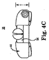
前述のように、脚94、100は、第1の関節連結部材90の脚94についての以下の記述が、第2の関節連結部材92の脚100に等しく適用できるように、同一であることが可能である。図4A(ヘッドリンクアセンブリ26を別様に、封入体44(図2A)、第2のポッド本体48(図2A)、および第2の関節連結部材92(図2A)が取り外された状態で図示説明する)に示すように、脚94は、ヒンジ機能96が形成されるか提供される第1の端110から、第1の端110の反対側の第2の端112に伸びる。この点に関し、第1および第2の端110、112の間の脚94の形状は、脚94が取り付けられる中間部分60の対応する領域の形状または曲げと概ね一致する。脚94は、図4Bおよび図4Cにおける寸法Tによって示されるようなチューブ40の主面に垂直をなす面内に厚さを規定する(図4Bおよび図4Cにおいて、封入体44が脚94を示し、実質的に覆うことが理解されるが、図4Bおよび図4Cに示す全体的な厚さTは、脚94の厚さの変化を表す)。図4Aから図4Cを参照すると、脚94の厚さTは、構造によっては、第1の端110から第2の端112に向けて徐々に減少する。別の言い方をすると、第1の端110は、第2の端112の厚さより厚い厚さを有する。この徐々に減少する厚さは、ヘッドリンクアセンブリ26に薄型特性を与え、手術部位の明視化の向上をもたらす。しかしながら、他の実施形態において、脚94は、より均一な厚さを有することができる。
As mentioned above, the
図2Aおよび図5を参照すると、ヒンジ機能96は、いくつかの実施形態において、(第1の端110で)脚94によって一体化して形成され、雌ヒンジ機能であることが可能である。これらの構造では、第2の関節連結部材92のヒンジ機能102は、対応する雄ヒンジ機能である。例えば、第1の関節連結部材90の雌ヒンジ機能96は、スロットまたはソケット114を備えているか規定することができる。スロット114は、曲がった、または円形の外縁部116を有し、対向する指118a、118bによって結合する。第2の関節連結部材92の雄ヒンジ機能102は、ピン120および対向する肩122a、122bを有するか規定する。ピン120は、肩122a、122bから、それぞれくぼみ124a、124bによって分離される。ピン120は、概ね円形を有し、スロット114内に回転自在に受け入れられる(すなわち、ピン120の円形が、スロット外縁部116の形状に概ね整合する)よう形成され、ピンのスロット内での支点を確立する。指118a、118bは、互いに対して関節連結部材90、92の明確な動きを限定するために働く肩122a、122bをそれぞれ用いて、くぼみ124a、124b内にスライド可能に組み込まれる。構造によっては、肩122a、122bの一方または両方は省略することができる。更に、多種多様な他の枢動型構成を使用することができ、図に示すものと異なる形式を想定するヒンジ機能96、102を有する。
With reference to FIGS. 2A and 5, the
回転停止をもたらすことに加えて、指118a、118bおよび肩122a、122bは、封入体44が関節連結部材90、92にオーバーモールドされたプラスチック材料である実施形態で、任意選択の封入体44(図2A)の材料が、ピン120とスロット114の間の境界面の領域に入ることを防ぐように働くことができる(例えば、溶融プラスチックで関節連結部材90、92の周囲に封入体44を成型する場合、指118a、118bおよび肩122a、122bが溶融プラスチックせき止めることで、溶融プラスチックがピン120とスロット114との間に流れないよう、または勢いよく流れ込まないようにする)。任意選択的に、関節連結部材90、92の一方または両方は、望ましくないプラスチック材料が境界面のピン120/スロット114領域に流れることを防ぐ、更なる機能を組み込むことができる。例えば、図6Aおよび図6Bに最も良く示すように、第1の関節連結部材90は、第1の端110に保護板124を更に備え、または形成することができる。保護板124は、スロット114の端に配置され、曲がった外縁部を有する。第2の関節連結部材92は、対応する溝126を形成する。図2Aを更に参照すると、スロット114内にピン120を枢動可能に組み立てる場合に、保護板124は、溝126内に回転自在に組み込まれ、ピン120の下に有効に広がる。したがって、保護板124は境界面のピン120/スロット114領域の下側を、封入体44の材料が流れることから保護し、ピンのスロット内での支点が所望の枢動を行うことをより確実にする。
In addition to providing rotation stop, the fingers 118a, 118b and
図2Aおよび図2Bに戻り、コレットインターフェース本体98、104は、同一であることが可能であり、第1の関節連結部材90のコレットインターフェース本体98についての以下の記述を、第2の関節連結部材92のコレットインターフェース本体104に同様に適用する。コレットインターフェース本体98は、いくつかの実施形態において、首130およびベース132を有する。首130は、脚94から、第1の端110(図4A)で、または第1の端110に隣接して、チューブ40とは概ね反対側の方向に伸びる。次に、ベース132は、脚94と反対側に、首130から伸び、(首130の表面領域と比較して)表面領域の拡大をもたらす。他の構造において、首130は省略することができる。いずれにしても、コレットインターフェース本体98、特にベース132は、内面140および外面142を形成、または規定する。内面140は平らであり、一方、外面142は丸みを帯びている。より詳しくは、少なくともベース132に沿う外面142は、ほぼ半球状、または半楕円状の形状であることが可能である。内面140が互いに接するようにコレットインターフェース本体98、104を構成する場合、外面142はボール状、球状、またはほぼ球状となるよう組み合わせる(例えば、外面142は、ボール、楕円、またはフットボール型形状等となるよう組み合わせることができる)。あるいは、他の形状も考えられる。
Returning to FIGS. 2A and 2B, the
関節連結部材90、92は、それぞれ、予想される力の下でその保全性を維持するよう選択された剛体材料から形成された一体式で均一の本体であることが可能である。いくつかの実施形態において、関節連結部材90、92は、射出形成金属(例えば、鋼鉄)でそれぞれ形成されるが、降伏することない拡がり動作の間にチューブ40を曲げて開くまたは広げるために、小断面において必要な強度をもたらすことが可能な他の材料(例えば、セラミック)も受け入れ可能である。
The
関節連結部材90、92は、様々な方法でチューブ40に取り付けることができる。拡げ機構42がチューブ40から別々に形成された構造では、関節連結部材90、92は、図4Aおよび図7Aに示すように、チューブ40の外部150に取り付けられる。例えば、関節連結部材90、92は、溶接、接着等によって、外面150に個別に取り付けることができる。あるいは、各関節連結部材90、92は、チューブ40に取り付けるために構成された1つまたは複数のクリップ152を備えている。図7Bは、第1の関節連結部材90と関連づけられたクリップ152をより詳細に示し、脚94の底面154は比較的平らで、チューブ40の外面150と概ね向かい合う(例えば、支える)ことが可能なことを示す。クリップ152は、底面154から突出しており、互いから水平方向に配置された対向するポスト156a、156bを含み、チューブ40を係合するよう形成された開口部158を規定する。構造によっては、ポスト156a、156bは、三角形状の端160でそれぞれ終端する。チューブ40が開口部158内に挿入されると、三角形の端160がチューブ40に対し押しつけられ、クリップ152に対して、したがって、脚94の幅に対してチューブ40を効率的に中心に配置する。他の取り付け技術も考えられ、したがって、任意選択のクリップ152が他の形式であることを想定することができる、および/または省略することができる。
The
図2Aおよび図2Bに戻り、チューブ40上の(または、チューブ40への)関節連結部材90、92の固定支持をさらに向上するために、封入体44を一体化することができる。一般論として、封入体44は、チューブ40および拡げ機構42にオーバーモールドされたプラスチック材料であり、部材40、42を恒久的に封止し、いくつかの実施形態において、他の接合作業の必要を無くす。封入体44は、非外傷性組織接触のための適切なデュロメータ硬度(例えば、85 Shore A)を示す適切な材料(例えば、ポリ塩化ビニル)で形成することができ、ヒンジ機能96、102またはコレットインターフェース本体98、104と干渉しないように構成または形成される。例えば、封入体44は、ヒンジ機能96、102が互いに境界面接触する領域、およびコレットインターフェース本体98、104が伸びる領域で、へこみ170(図2A)を規定する方法で成形することができる。オーバーモールドされた封入体44がヒンジ機能96、102の間の境界面領域内に勢いよく流れ込まない、または流れないことをより確実にするために、任意選択の肩122a、122bおよび/または保護板124(図6A)を、上記のように提供することができる。封入体44の成形には、真空チューブアセンブリ34(図1)への接続のための真空ポート172の形成も備えていることができる。図7Aは、真空ポート172がチューブ吸気口78に、したがって、管腔76に流体的に接続されることを示す。含まれる場合、封入体44は、ヘッドリンクアセンブリインターフェースへの柔軟/弾力的な真空ライン、チューブ40への拡げ機構42の安全な取り付け、鋭いまたは粗い金属の特徴をマスクすることによる組織剥離の防止、チューブ40の拡がりを可能にする柔軟性と適合性、および/または、拡がった後にチューブ40を初期状態に復帰させるのを助けるための弾力性等の1つまたは複数の機能を提供する。封入体44は、他の形式を想定することができ、本開示によって考えられる他の実施形態においては省略することができる。
Returning to FIGS. 2A and 2B, the
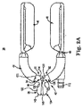
図8Aを参照すると、最終構造時に、ヘッドリンクアセンブリ26は、先端68、70(図では隠れているが、概略を示す)が自然間隔SNで水平方向に配置される初期状態を自動的にとる。初期状態、特に自然間隔SNは、チューブ40の形状記憶特性、および/または封入体44によって伝えられる形状補強特性によって規定される。いずれにしても、初期状態において、コレットインターフェース本体98、104が、対応する脚94、100から伸びて整列する間に、テーパ状ギャップ180が対応する内面140の間に規定される。ヘッドリンクアセンブリ26は、以下に記載するように、コレットインターフェース本体98、104を圧縮力にさらすことにより、図8Bの伸張状態に移行することができる。圧縮力は内面140を、対応するインターフェース本体98、104の全体に沿って互いに接触、またはほぼ接触させる。次に、圧縮力は、対応する脚94、100に移り、ヒンジ機能96、102を介して互いに対し脚94、100を枢動させる。脚94、100の枢動はチューブ40上に伝わり、アーム62、64(図では隠れているが、概略を示す)を互いに離して広げさせ、伸張状態における先端68、70の間の伸張間隔SEをもたらす。外部の圧縮力を除去すると、ヘッドリンクアセンブリ26は図8Aの初期状態に自己移行することができ、アーム62、64が自然間隔SNに戻る。初期状態への復帰は、チューブ40の形状記憶特性および/または封入体44の弾力性により発生可能である。
Referring to FIG. 8A, during the final construction, the
図1に戻り、細長いアーム22は、様々な形式を想定することができ、構造によっては、関節連結アームである。例えば、関節連結の細長いアーム22は、複数の「ボールおよびソケット」リンク200を備えることができ、薄壁の弾性シースで覆うことができる。関節連結の細長いアーム22の許容できる構造のいくつかは、特許文献4および特許文献5に記載され、どちらもその全体が参照により本明細書に組み込まれる。更に他の実施形態において、関節連結機能は、「ボールおよびソケット」リンク以外の構造を介して、細長いアーム22に実装することができる。あるいは、細長いアーム22は、剛体チューブまたは中実軸であることも可能である。
Returning to FIG. 1, the elongate arm 22 can assume various forms and, depending on the structure, is an articulating arm. For example, the articulated elongate arm 22 can include a plurality of “ball and socket”
細長いアーム22の正確な構造にかかわらず、ケーブルなどの張力要素202が提供されることがあり、図9に示すように、細長いアーム22を貫通して伸びる。例えば、張力要素202は、細長いアーム22のリンク200を通り、遠位端204でコレット24に、および近位端206でハンドル32に結合する。‘628特許および‘879公報により詳細に記載されるように、張力要素202は、ハンドル32の回転による張力にさらされる可能性があり、次に、張力要素202を近位側へ移動させ、それに対応して、関節連結アーム22の部材をしっかり締め、さらに、コレット24に対してヘッドリンクアセンブリ26(図1)の位置を安定化する。張力要素202は、他の形式を想定することができ、細長いアーム22に対する張力要素202の関係を想定することができる。いずれにしても、組織スタビライザ20は、以下に記載するように、利用者がコレット24をしっかり締めることを実現することを可能にする、1つまたは複数の機能を有している。
Regardless of the exact structure of the elongated arm 22, a
図1に戻り、コレット24は、様々な形式を想定することができ、コレットアセンブリ230の一部として提供することができる。例えば、図10は、コレットを受ける要素232、コレット24、張力要素202、およびヘッドリンクアセンブリ26のコレットインターフェース本体98、104を含んでいるようなコレットアセンブリ230の一実施形態を示す。一般論として、コレット24は、コレットを受ける要素232のボア234内にスライド可能に受け入れられ、(例えば、端が丸みを帯びているシャンク236を介して)張力要素202に接続される。次に、張力要素202は、コレットを受ける要素232において、経路238を通って伸びる。参考として、コレットを受ける要素232は、細長いアーム22に取り付けることができる、または細長いアーム22の一部として形成することができる。コレットインターフェース本体98、104は、コレット24のヘッド242によって規定される空隙240内に受け入れられる。図10の解放状態において、ヘッド242はコレットを受ける要素232の遠位端244に遠位に設置され、コレットを受ける要素232が明白な圧縮力をヘッド242上に印加しないようにする。したがって、コレットインターフェース本体98、104は、互いからわずかな間隔を維持し、空隙240内で、共に自由に回転することができる。
Returning to FIG. 1, the
コレットヘッド242は、ボア234の直径より大きい、図10に示す通常の直径から半径方向に折りたたみ可能である。コレットアセンブリ230は、張力要素202に張力または引張力を印加することによって、固定状態に移行することができ、それにより、コレットを受ける要素232のボア234内にコレットヘッド242を後退することができる。この構成では、コレットを受ける要素232は、圧縮力をコレットヘッド242に印加し、次に、コレットヘッド242をコレットインターフェース本体98、104上に押しつけるために力を加える。その結果、圧縮力がコレットインターフェース本体98、104に印加され、ヘッドリンクアセンブリ26がコレット24に効率的に空間的に固定される。更に、上記のように、この圧縮力はヘッドリンクアセンブリアーム62、64の拡がりを実現する。コレットアセンブリ230は、上記のものと異なる他の構造を想定することができる。例えば、他の構造において、張力要素202および/またはコレットを受ける要素232を伴うことができる、または伴うことができない様々な他の方法で、コレット24は細長いアーム22に結合することができる。
The
図1に戻り、一般に、クランプ28は、リトラクタ(図示しない)に選択的に取り付けるために構成され、したがって、クランプ状構造を実装する様々な形式を想定することができる。クランプ28は、組織スタビライザ20を、従来の外科手術用リトラクタ、または手術部位に固定された関係で設置された他の設備に取り付けるよう設計される。
Returning to FIG. 1, in general, the
タレット30は、提供される場合、クランプ28に対する細長いアーム22の回転を実現するように働く。例示的に、タレット30の非限定的な記述が、‘628特許および‘879公報に提供されており、その教示は参照によって本明細書に組み込まれる。他の構造も考えられる。更に他の実施形態において、タレット30は省略することができる。
The turret 30 serves to provide rotation of the elongated arm 22 relative to the
ハンドル32は極めて定型化した実施形態で示されるが、以下に記載するようなハンドルの機能を実行するどのような機器でも十分であろう。一般論として、ハンドル32は、利用者が組織スタビライザ20を簡便に扱うことを提供し、ならびに、1つまたは複数の組織スタビライザ20の機能を利用者が操作することを提供する。例えば、細長いアーム22が、それを通って伸びる張力要素を有する関節連結アームである実施形態では、ハンドル32は、所望の形状で細長いアーム22を固定するよう作動する(例えば、回転する)ことができる。同様に、ハンドル32は、上記のようにヘッドリンクアセンブリ26に対してコレット24の固定および解放、ならびにヘッドリンクアセンブリアーム62、64の拡がりを実現するよう操作することができる。したがって、組織スタビライザ20は、「自動的な」拡がり機能をもたらし、利用者がハンドル32を簡単に動かし、伸張状態にヘッドリンクアセンブリ26を自己移行するよう促す。
Although the
最後に、真空チューブアセンブリ34は、負の圧力または真空をヘッドリンクアセンブリ26に伝えるために適切な任意の形式を想定することができ、管280および弁282を備えていることができる。提供された場合、弁は負の圧力源(図示しない)に流体的に接続可能であり、管280を用いて負の圧力源に、選択的に、流体的に接続する。次に、管280は負の圧力をヘッドリンクアセンブリ26に(例えば、真空ポート172を介して)伝える。他の構造において、弁は省略することができる。
Finally, the vacuum tube assembly 34 can assume any form suitable for delivering negative pressure or vacuum to the
組織スタビライザ20は、様々な外科的処置、および/またはそのような処置の一部を実行するために使用することができる。図11に示すように、組織スタビライザ20は、胸骨リトラクタ350にクランプするか取り付けることができ、患者の心臓352の組織を安定化するために使用することができる。例えば、ヘッドリンクアセンブリ26は、ヘッドリンクアセンブリ26が、特定の手術部位によって影響を受ける事実上どんな空間配向に、コレット24に対して(従って、細長いアーム22に対して)、(ヨー、ピッチ、およびロールの点から)自由に回転および枢動(軸を中心に回動)することを可能にする方法で、コレット24(図1)に最初に取り付けられる。したがって、ポッド本体46、48は、例えば、「トゥーズアップ(toes up)」「トゥーズダウン(toes down)」および/または「トゥーズツーサイド(toes−to−the−side)」位置等の様々な空間配向に配置することができる。いずれにしても、ヘッドリンクアセンブリ26は、先端68、70(図8A)が自然間隔SN(図8A)をとる初期状態にある。ヘッドリンクアセンブリ26が所望の位置でひとたび空間的に方向付けられると、負の圧力が、真空チューブアセンブリ34を介してヘッドリンクアセンブリ26に供給される。負の圧力はアーム62、64(図2A)に伝えられ、吸引カップ80(図2B)で吸引力を確立する。次に、吸引力は、接触した組織を、ヘッドリンクアセンブリ26との係合に引き寄せる。次いで、ヘッドリンクアセンブリ26は、例えば、上記のようにコレット24を介してコレットインターフェース本体98、104(図2A)に圧縮力を印加することによって、上記の伸張状態に移行する。伸張状態に移行すると、アーム62、64は、(図8Bの伸張間隔SEに)互いから離れて拡がり、それにより、係合する組織を延伸する。外科的処置が終了し、負の圧力の供給を停止すると、ヘッドリンクアセンブリ26は組織から離れる。更に、コレットインターフェース本体98、104にかけられた圧縮力が外されると、ヘッドリンクアセンブリ26は、初期状態に自己復帰する。同じ処置を心臓352の異なる位置で繰り返すことができ(例えば、複数の血管移植手術)、これは、ヘッドリンクアセンブリ26が初期状態と伸張状態の間を繰り返し移行可能であるためである。
The
本開示の組織スタビライザは、以前の設計に際だった改良を提供する。自動的なポッド拡がり機能は、誤用に対し堅牢であり、極めて予測可能で再現可能である。いくつかの実施形態において、ヘッドリンクアセンブリは、真空マニホールド、アセンブリ封入、および部材を動かすための柔軟性と適合性のための機能を実装する。これらの機能を合わせて、単純、薄型、極めて堅固、高い信頼性、および製造の容易な、自動的にポッドが広がるヘッドリンクアセンブリを提供する。 The tissue stabilizer of the present disclosure provides an improvement over previous designs. The automatic pod expansion feature is robust against misuse and is highly predictable and reproducible. In some embodiments, the head link assembly implements functions for flexibility and compatibility for moving the vacuum manifold, assembly encapsulation, and members. Together, these features provide a head link assembly that is simple, thin, extremely robust, highly reliable, and easy to manufacture, with an automatically expanding pod.
他の実施形態の組織スタビライザ400を図12に示す。組織スタビライザ400は、上記の組織スタビライザ20(図1)に類似しており、一般に、細長いアーム402、コレット404、およびヘッドリンクアセンブリ406を備えている。コレット404は細長いアーム402の遠位端に配置され、ヘッドリンクアセンブリ406はコレット404に回転自在に結合される。図示しないが、接触した組織に吸引力を印加するために、負の圧力源をヘッドリンクアセンブリ406に流体的に接続することができる。
Another embodiment of
任意選択的に関節連結アームである上記の細長いアーム22(図1)と違って、細長いアーム402は剛性部材であり、したがって、低侵襲的処置(例えば、直視開胸)で用いるために適している。細長いアーム402は、鋼鉄等の剛性材料で形成された管状の部材とすることが可能である。
Unlike the elongate arm 22 (FIG. 1), which is optionally an articulating arm, the
図13に最も良く示すように、組織スタビライザ400は、コレット404がヘッドリンクアセンブリ406と恒久的に関連づけられ、細長いアーム402と着脱可能に接続されるように構成される。この点を考慮して、コレット404は、ヘッド410、肩412、およびタング414を備え、または形成する。ヘッド410は、以下に記載するように、ヘッドリンクアセンブリ406の球形部材408を回転自在に受け入れるように構成され、一般に空隙(図13では隠れている)を規定する。構造によっては、ヘッド410は、肩412から遠位端418に伸びる複数の離間された指416によって規定される。指416は、互いに対して半径方向に変形可能であり、肩412で枢動(軸を中心に回動)する。遠位端418で規定される全体の直径がコレット402の初期状態においてヘッドリンクアセンブリ406の球形部材408を保持するような大きさであるとともに、球形部材408はヘッド410内を自由に回転可能である。外部の圧縮力にさらされると、以下に記載するように、指416は互いに向けて半径方向に内側に曲がり、固定状態において球形部材408とより堅固に係合する。コレット404に対してヘッドリンクアセンブリ406の動きの範囲をより完全にするために、拡大されたギャップ420(その1つを図13に示す)が、遠位端418で指416の隣接する指の間に規定され得る。ギャップ420は、ヘッドリンクアセンブリ406のシャフト部材422の通過を可能にするように形成される。
As best shown in FIG. 13, the
タング414は、肩412から、ヘッド410の反対方向に伸び、細長いアーム402と接続するよう構成される。構造によっては、タング414は、その前側部(leading side)432と後側部(trailing side)434の間に外周溝430を規定する。外周溝430は、以下で明らかとされる理由のため、丸みを帯びた湾曲を有する。いずれにしても、溝430に沿うタング414の直径は、前側部432および後側部434の直径未満である。
The
ヘッドリンクアセンブリ406は多種多様な形式を有することができ、構造によっては、チューブ440、ポート442、および上記したような軸422と球形部材408を維持するフレーム444を備えている。チューブ440は、ポッド本体450、452がそれぞれ取り付けられる対向するアーム446、448を形成、または規定する。いくつかの実施形態において、チューブ440は、各アーム446、448に形成された開口部454に流体的に接続された、および対応するポッド本体450、452に流体的に接続された単一の管腔(隠れている)を形成する。次に、ポート442は、管腔に流体的に接続され、真空管(図示しない)を分ける接続点を確立する。他の実施形態において、別々の管腔を、各アーム446、448に対して個々に確立することができる。いずれにしても、チューブ440、特にアーム446、448は、利用者が、アーム446、448(ひいては、ポッド本体450、452)を互いに対して所望の空間配向に操作することが可能である、可鍛性があるが剛性の材料(例えば、鋼鉄)で形成することができる。
The
フレーム444は、チューブ440から、アーム446、448と反対方向に伸び、球形部材408からチューブ440をずらす、または距離を空けて配置するよう働く。フレーム444は、保護カバー内に埋め込むことができる。他の実施形態において、フレーム444は、省略することができる。
The frame 444 extends from the
上記のヘッドリンクアセンブリ26(図1)と違い、組織スタビライザ400のヘッドリンクアセンブリ406は、自動拡がり機能を必ずしも実装する必要はない。したがって、例えば、上記の拡げ機構42(図2A)は、チューブ440に取り付けてもよく、または取り付けなくてもよい。
Unlike the head link assembly 26 (FIG. 1) described above, the
様々な構造を使用して、コレット404の細長いアーム402との結合を実現することができる。例えば、構造によっては、細長いアーム402は、遠位端462と隣接するボールベアリングアセンブリ460(概略を示す)を備えていることができ、ボールベアリングアセンブリ460は外周溝430を介してタング414を回転自在に捕らえる。細長いアーム402は、コレット404の選択的な接続および非接続を容易にするよう構成される。例えば、細長いアーム402は、外側チューブ470と内側軸472を備えることができる。外側チューブ470は、遠位端462と隣接する内部の解放開口部474を形成する。内側軸472は、外側チューブ470内にスライド可能に保持され、ボールベアリングアセンブリ460がその先導端(leading end)476で保持される。後端部(trailing end)(図示しない)は外側チューブ470を通って伸び、図12に示すようなハンドル478等のアクチュエータに結合される。この構造では、利用者は、ハンドル478の操作を介して、外側チューブ470に相関して内側軸472を長手方向に動かすことができる。
A variety of structures can be used to achieve coupling of the
上記の構造では、コレット404は、図14Aに示す平行移動可能な状態でアーム402に接続することができ、コレット404のタング414はボールベアリングアセンブリ460に結合され、内側軸472の先導端476は外側チューブ470内に後退する。解放開口部474は、アセンブリ460のボールベアリング480が溝430に誘導されるように、ボールベアリングアセンブリ460から長手方向にずらされる。その結果、タング414は細長いアーム402に対して捕らえられる。しかしながら、平行移動可能な状態において、外側チューブ470の遠位端462は、コレットヘッド410から近位側にずらされ、最小の圧縮力が、もしあれば、アーム402によってコレットヘッド410に印加され、次に、コレットヘッド410は球形部材408上に最低限に圧縮される。したがって、ヘッドリンクアセンブリ406はコレット404に対して自由に枢動(軸を中心に回動)および回転(ヨー、ピッチ、およびロール)することができ、利用者が所望の空間配向を選択することが可能となる。ヘッドリンクアセンブリ406がひとたび所望の向きに向いたら、アーム402/コレット404接続部は、外側チューブ470に対して内側軸472を後退すること、および/または内側軸472に対して外側チューブ470を遠位側に進めることによって、図14Bの固定状態に移行する。例えば、構造によっては、ハンドル478(図12)は、回転して、内側軸472のわずかな後退を実現することができる。いずれにしても、内側軸472が後退すると、コレット404は外側チューブ470に対して同様に近位側に後退し、したがって、外側チューブ470の遠位端462は、より明白な圧縮力をコレットヘッド410上に印加する。次いで、固定状態において、外側チューブ470はヘッド410を球形部材408上に圧縮し、それにより、ヘッドリンクアセンブリ406を選択された空間配向で固定する。
In the above structure, the
希望であれば、アーム402を図14Cの解放状態に移行することによって、コレット404をアーム402から切り離すことができる。特に、内側軸472は、ボールベアリングアセンブリ460が解放開口部474と長手方向に整列するまで、外側チューブ470に対して遠位側に進む。解放開口部474は、ボールベアリング480を部分的に受け入れるように形成され、ボールベアリング480は、タング溝430から外れる、または解放されることが可能となる。解放状態において、利用者は、ボールベアリングアセンブリ460からタング414を外側に簡単に引くことが可能であり、それにより、コレット404/ヘッドリンクアセンブリ406を細長いアーム402から外すことが可能となる。細長いアーム402へのコレット404/ヘッドリンクアセンブリ406の再接続は、逆の方法で実現することができる。
If desired, the
上記のような組織スタビライザ400は、ヘッドリンクアセンブリ406がすぐに外れることが有益である外科的処置に高く寄与する。例えば、組織スタビライザ400は、低侵襲的(例えば、直視開胸)冠状動脈バイパス移植処置で使用することができる。上記の迅速な接続/切断構成を介しての狭い空間内でのヘッドリンクアセンブリ406の柔軟で簡単な接続は、以前の設計に顕著な利点をもたらす。
The
本開示は好適な実施形態に関して記載したが、当業者は、本開示の主旨と範囲から離れることなく、形状および詳細を変更することが可能であることを認識するであろう。 Although the present disclosure has been described with reference to preferred embodiments, those skilled in the art will recognize that changes can be made in form and detail without departing from the spirit and scope of the disclosure.
Claims (30)
遠位端で終端する細長いアームと、
前記遠位端に配置されるコレットと、
前記コレットに回転自在に結合可能なヘッドリンクアセンブリとを備え、
前記ヘッドリンクアセンブリが、負の圧力を組織に印加するチューブを有し、
前記チューブが、中間部分と、前記中間部分から伸び先端で終端する第1のアームと、前記中間部分から前記第1のアームの反対側に伸び先端で終端する第2のアームと、を備え、
前記ヘッドリンクアセンブリは、さらに、拡げ機構を備え、該拡げ機構は、それぞれが脚と対応する前記脚から突出するコレットインターフェース本体を有する第1および第2の関節連結部材を備え、前記第1の関節連結部材は更に雌ヒンジ特徴部を含み、前記第2の関節連結部材は更に前記雌ヒンジ特徴部と形状が異なり前記雌ヒンジ特徴部に回動可能に結合できるように構成された雄ヒンジ特徴部を有し、
最終組立時に、前記脚はそれぞれ前記中間部分の不連続領域に取り付けられ、前記雄ヒンジ特徴部は前記雌ヒンジ特徴部に枢動可能に結合され、
前記ヘッドリンクアセンブリは、前記先端の間に第1の水平方向距離を有する初期状態から、前記コレットインターフェース本体上に伝えられる圧縮力に応じて前記先端の間に第2の水平方向距離を有する伸張状態に移行可能であり、前記第1の水平方向距離は前記第2の水平方向距離未満である、
ことを特徴とする組織スタビライザ。 An organization stabilizer,
An elongated arm that terminates at the distal end;
A collet disposed at the distal end;
A head link assembly rotatably coupled to the collet;
The head link assembly includes a tube for applying a negative pressure to the tissue;
The tube comprises an intermediate portion, a first arm extending from the intermediate portion and terminating at a leading end, and a second arm extending from the intermediate portion to the opposite side of the first arm and terminating at the leading end;
The head link assembly further includes an expansion mechanism, the expansion mechanism including first and second articulation members each having a collet interface body protruding from the leg corresponding to a leg, articulating member further comprises a female hinge feature, the second articulating member further said female hinge feature and configured male hinge such shapes can be rotatably coupled to a different Do Ri said female hinge feature It has a feature,
During final assembly, the legs are each attached to a discontinuous region of the intermediate portion, and the male hinge feature is pivotally coupled to the female hinge feature ;
The head link assembly extends from an initial state having a first horizontal distance between the tips to have a second horizontal distance between the tips in response to a compressive force transmitted on the collet interface body. Transition to a state, wherein the first horizontal distance is less than the second horizontal distance;
A tissue stabilizer characterized by that.
請求項1に記載の組織スタビライザ。 The tube is U-shaped;
The tissue stabilizer according to claim 1.
請求項1に記載の組織スタビライザ。 The tube is metal;
The tissue stabilizer according to claim 1.
請求項1に記載の組織スタビライザ。 Each of the arms forms a plurality of vacuum openings;
The tissue stabilizer according to claim 1.
請求項4に記載の組織スタビライザ。 The tube forms a continuous lumen fluidly connected to each of the openings;
The tissue stabilizer according to claim 4.
請求項5に記載の組織スタビライザ。 The intermediate portion forms a single inlet that fluidly connects a negative pressure source with the lumen;
The tissue stabilizer according to claim 5.
請求項6に記載の組織スタビライザ。 An axis of the inlet is aligned with an axis of the first arm;
The tissue stabilizer according to claim 6.
前記第1のアームに取り付けられる第1のポッド本体と、
前記第2のアームに取り付けられる第2のポッド本体と、を更に備え、
前記第1および第2のポッド本体がポリマーから形成され、それぞれが、前記対応するアームにおける前記開口部のそれぞれに流体的に接続される複数のカップを規定する、
請求項4に記載の組織スタビライザ。 The head link assembly comprises:
A first pod body attached to the first arm;
A second pod body attached to the second arm,
The first and second pod bodies are formed from a polymer, each defining a plurality of cups fluidly connected to each of the openings in the corresponding arm;
The tissue stabilizer according to claim 4.
請求項1に記載の組織スタビライザ。 The intermediate portion has a curved shape defining an intermediate point between the arms, and further, the first leg extends from the intermediate point toward the first arm and matches the bending of the intermediate portion. Make up bending,
The tissue stabilizer according to claim 1.
請求項9に記載の組織スタビライザ。 The second leg extends from the midpoint toward the second arm and constitutes a bend that matches the bend of the midsection;
The tissue stabilizer according to claim 9.
請求項10に記載の組織スタビライザ。 The male and female hinge features combine to form a fulcrum pivot at the midpoint;
The tissue stabilizer according to claim 10.
請求項10に記載の組織スタビライザ。 The collet interface body is disposed at the midpoint;
The tissue stabilizer according to claim 10.
請求項9に記載の組織スタビライザ。 The leg of the first joint connecting member defines an inner surface adjacent to the outside of the tube, and the first joint connecting member further protrudes from the inner surface and is coupled to the outside of the tube. With
The tissue stabilizer according to claim 9.
請求項13に記載の組織スタビライザ。 The inner surface is flat,
The tissue stabilizer according to claim 13.
請求項1に記載の組織スタビライザ。 The female hinge feature includes a slot formed by the leg of the first articulation member, and the male hinge feature comprises a pin formed by the leg of the second articulation member. The slot is configured to be indirectly connected so as to be rotatable about the pin.
The tissue stabilizer according to claim 1.
請求項15に記載の組織スタビライザ。 The pin pivots relative to the slot about an axis defined to be perpendicular to a major surface of the tube;
The tissue stabilizer according to claim 15.
請求項1に記載の組織スタビライザ。 The leg of the first articulation member extends from a first end defined by the female hinge feature to a second end opposite the first end, and further at the first end. A thickness of the leg of the first joint connecting member mechanism in a plane perpendicular to the main surface of the tube is thicker than a thickness of the second end;
The tissue stabilizer according to claim 1.
請求項1に記載の組織スタビライザ。 The collet interface body is coupled to define a spherical shape;
The tissue stabilizer according to claim 1.
前記拡げ機構の一部上と前記チューブの一部上に配置されて前記拡げ機構を前記チューブに堅固に結合する封入体を備えている、
請求項1に記載の組織スタビライザ。 The head link assembly further includes
An enclosure disposed on a portion of the expansion mechanism and a portion of the tube to securely couple the expansion mechanism to the tube;
The tissue stabilizer according to claim 1.
請求項19に記載の組織スタビライザ。 The enclosure is a plastic material formed on the spreading mechanism and the tube.
The tissue stabilizer according to claim 19.
請求項19に記載の組織スタビライザ。 The inclusion body defines a dent in the region of the hinge feature and the collet interface body;
The tissue stabilizer according to claim 19.
請求項1に記載の組織スタビライザ。 The elongate arm is an articulating arm having a tension element extending therethrough, and further, when the collet interface body is disposed within the collet and pulling the tension element, the head link assembly is brought into the extended state. The collet is coupled to the tension element such that the collet applies a compressive force on the collet interface body during transition;
The tissue stabilizer according to claim 1.
請求項22に記載の組織スタビライザ。 When the tension element is loosened, the compressive force applied to the collet interface body decreases and the head link assembly self-transitions to the initial state;
23. A tissue stabilizer according to claim 22.
遠位端で終端する細長いアームと、
前記遠位端に配置されたコレットと、
前記コレットに回転自在に結合可能なヘッドリンクアセンブリとを備え、
前記ヘッドリンクアセンブリは、負の圧力を組織に印加する、外面と管腔を規定するチューブ備え、該チューブは、中間部分と、前記中間部分から伸び先端で終端する第1のアームと、前記中間部分から前記第1のアームと反対方向に伸び先端で終端する第2のアームとを形成し、
前記ヘッドリンクアセンブリはさらに、前記チューブから離れて形成され、前記チューブの外面に取り付けられた拡げ機構とを有し、前記拡げ機構が、脚、コレットインターフェース本体、およびヒンジ特徴部をそれぞれ有する第1および第2の関節連結部材を有し、
前記チューブの前記外面に前記拡げ機構を取り付けるときに、前記脚を前記中間部分に取り付け、前記ヒンジ特徴部が互いに枢動可能に結合され、
前記ヘッドリンクアセンブリが、前記先端の間に第1の水平方向距離を有する初期状態から、前記コレットインターフェース本体上に伝えられた圧縮力に応じて前記先端の間に第2の水平方向距離を有する伸張状態に移行可能であり、前記第1の水平方向距離が前記第2の水平方向距離未満である、
組織スタビライザ。 An organization stabilizer,
An elongated arm that terminates at the distal end;
A collet disposed at the distal end;
A head link assembly rotatably coupled to the collet;
The head link assembly applies a negative pressure to the tissue, comprising a tube defining an outer surface and the lumen, the tube is a middle portion, a first arm terminating elongation at a tip from said intermediate portion, said intermediate Forming a second arm extending from the portion in the opposite direction to the first arm and terminating at the tip;
The head link assembly further is formed away from the tube, and a mechanism spread attached to the outer surface of the tube, the spreading mechanism, first with legs, collet interface body, and the hinge features respectively and a second articulating member,
When attaching the spreading mechanism to the outer surface of the tube, the leg is attached to the intermediate portion and the hinge features are pivotally coupled to each other;
The head link assembly has a second horizontal distance between the tips in response to a compressive force transmitted on the collet interface body from an initial state in which the head link assembly has a first horizontal distance between the tips. Transition to a stretched state, wherein the first horizontal distance is less than the second horizontal distance;
Tissue stabilizer.
請求項24に記載の組織スタビライザ。 The tube is U-shaped;
25. A tissue stabilizer according to claim 24.
請求項24に記載の組織スタビライザ。 Each of the legs forms a plurality of vacuum openings fluidly connected to the lumen;
25. A tissue stabilizer according to claim 24.
請求項24に記載の組織スタビライザ。 The intermediate portion has a curved shape defining an intermediate point between the arms, and further, the first leg extends from the intermediate point toward the first arm and matches the bending of the intermediate portion. Defining a bend, wherein the second leg extends from the intermediate point toward the second arm and defines a bend that matches the bend of the intermediate portion;
25. A tissue stabilizer according to claim 24.
請求項27に記載の組織スタビライザ。 The collet interface body is disposed at the midpoint;
28. The tissue stabilizer of claim 27.
前記拡げ機構の一部上と前記チューブの一部上に配置されて前記拡げ機構を前記チューブに堅固に結合する封入体を備えている、
請求項24に記載の組織スタビライザ。 The head link assembly further includes
An enclosure disposed on a portion of the expansion mechanism and a portion of the tube to securely couple the expansion mechanism to the tube;
25. A tissue stabilizer according to claim 24.
請求項24に記載の組織スタビライザ。 The elongate arm is an articulating arm having a tension element extending therethrough, and further, when the collet interface body is disposed within the collet and pulling the tension element, the head link assembly is brought into the extended state. The collet is coupled to the tension element such that the collet applies a compressive force on the collet interface body for transition;
25. A tissue stabilizer according to claim 24.
Applications Claiming Priority (3)
| Application Number | Priority Date | Filing Date | Title |
|---|---|---|---|
| US12/846,147 | 2010-07-29 | ||
| US12/846,147 US8460172B2 (en) | 2010-07-29 | 2010-07-29 | Tissue stabilizing device and methods including a self-expandable head-link assembly |
| PCT/US2011/044876 WO2012015668A1 (en) | 2010-07-29 | 2011-07-21 | Tissue stablizing device and methods including a self-expandable head-link assembly |
Publications (3)
| Publication Number | Publication Date |
|---|---|
| JP2013535274A JP2013535274A (en) | 2013-09-12 |
| JP2013535274A5 JP2013535274A5 (en) | 2014-09-11 |
| JP5846506B2 true JP5846506B2 (en) | 2016-01-20 |
Family
ID=44629401
Family Applications (1)
| Application Number | Title | Priority Date | Filing Date |
|---|---|---|---|
| JP2013521835A Active JP5846506B2 (en) | 2010-07-29 | 2011-07-21 | Tissue stabilization device and method with self-extensible head link assembly |
Country Status (4)
| Country | Link |
|---|---|
| US (2) | US8460172B2 (en) |
| EP (1) | EP2598042B1 (en) |
| JP (1) | JP5846506B2 (en) |
| WO (1) | WO2012015668A1 (en) |
Families Citing this family (13)
| Publication number | Priority date | Publication date | Assignee | Title |
|---|---|---|---|---|
| EP3187119B1 (en) | 2010-06-14 | 2020-07-15 | Maquet Cardiovascular LLC | Surgical organ stabilizer instruments |
| WO2015061775A1 (en) | 2013-10-26 | 2015-04-30 | The United States Of America, As Represented By The Secretary, Department Of Health & Human Services | Atrial appendage ligation |
| US9730755B2 (en) | 2014-01-31 | 2017-08-15 | Medtronic Cryocath Lp | Medical device with adjustable flexibility |
| WO2015164700A1 (en) * | 2014-04-25 | 2015-10-29 | Trimarche Robert | Self-retaining retractor with integrated suction and light source |
| US9941406B2 (en) * | 2014-08-05 | 2018-04-10 | Taiwan Semiconductor Manufacturing Company, Ltd. | FinFETs with source/drain cladding |
| US10013808B2 (en) * | 2015-02-03 | 2018-07-03 | Globus Medical, Inc. | Surgeon head-mounted display apparatuses |
| JP2018517507A (en) | 2015-06-11 | 2018-07-05 | ハウメディカ・オステオニクス・コーポレイション | Spinal fixation targeting system and method for posterior spine surgery |
| US10149672B2 (en) | 2015-06-30 | 2018-12-11 | Emory University | Devices and methods for stabilizing tissue |
| CN107896483B (en) | 2016-01-29 | 2020-07-31 | 法尔扎姆·法拉曼德 | Minimally invasive heart stabilizer |
| WO2018039403A1 (en) * | 2016-08-24 | 2018-03-01 | Terumo Cardiovascular Systems Corporation | Heart rotator |
| US11877764B2 (en) * | 2017-05-23 | 2024-01-23 | Sumitomo Bakelite Co., Ltd. | Coronary artery bypass surgery treatment tool, treatment tool part, medical connector, and medical device |
| US10337666B2 (en) * | 2017-10-12 | 2019-07-02 | Paul Reitberger | Flashlight mount |
| US9945510B1 (en) * | 2017-10-12 | 2018-04-17 | Paul Reitberger | Flashlight mount |
Family Cites Families (43)
| Publication number | Priority date | Publication date | Assignee | Title |
|---|---|---|---|---|
| NL106631C (en) | 1960-02-04 | 1963-11-15 | Pieter Johannes Meijs | SUPPORT AND LOCKING DEVICE, IN PARTICULAR FOR A TIMER |
| US4949927A (en) | 1989-10-17 | 1990-08-21 | John Madocks | Articulable column |
| US5348259A (en) | 1992-02-10 | 1994-09-20 | Massachusetts Institute Of Technology | Flexible, articulable column |
| AU4849793A (en) * | 1992-09-03 | 1994-03-29 | Minnesota Scientific, Inc. | Laparoscope holder |
| US5513827A (en) | 1993-07-26 | 1996-05-07 | Karlin Technology, Inc. | Gooseneck surgical instrument holder |
| US5807243A (en) | 1994-08-31 | 1998-09-15 | Heartport, Inc. | Method for isolating a surgical site |
| US5836311A (en) | 1995-09-20 | 1998-11-17 | Medtronic, Inc. | Method and apparatus for temporarily immobilizing a local area of tissue |
| US5727569A (en) | 1996-02-20 | 1998-03-17 | Cardiothoracic Systems, Inc. | Surgical devices for imposing a negative pressure to fix the position of cardiac tissue during surgery |
| CA2197614C (en) * | 1996-02-20 | 2002-07-02 | Charles S. Taylor | Surgical instruments and procedures for stabilizing the beating heart during coronary artery bypass graft surgery |
| US5947896A (en) | 1996-04-26 | 1999-09-07 | United States Surgical Corporation | Heart stabilizer apparatus and method for use |
| US6152874A (en) | 1996-04-26 | 2000-11-28 | Genzyme Corporation | Adjustable multi-purpose coronary stabilizing retractor |
| US5967973A (en) | 1996-04-26 | 1999-10-19 | United States Surgical | Surgical retractor and method of surgery |
| US5976080A (en) | 1996-09-20 | 1999-11-02 | United States Surgical | Surgical apparatus and method |
| WO1998049944A1 (en) | 1997-05-02 | 1998-11-12 | Pilling Weck Incorporated | Adjustable supporting bracket having plural ball and socket joints |
| US5876332A (en) | 1997-07-24 | 1999-03-02 | Genzyme Corporation | Surgical support member |
| US6019722A (en) | 1997-09-17 | 2000-02-01 | Guidant Corporation | Device to permit offpump beating heart coronary bypass surgery |
| US6013027A (en) | 1997-10-07 | 2000-01-11 | Ethicon Endo-Surgery, Inc. | Method for using a tissue stabilization device during surgery |
| US6007486A (en) | 1997-10-07 | 1999-12-28 | Ethicon Endo-Surgery, Inc. | Tissue stabilization device for use during surgery having a segmented shaft |
| US6193652B1 (en) | 1997-10-07 | 2001-02-27 | Ethicon Endo-Surgery, Inc. | Tissue stabilization device for use during surgery having spherical curved feet |
| EP1049409A4 (en) | 1998-01-23 | 2009-09-09 | United States Surgical Corp | Surgical instrument |
| US6113534A (en) | 1998-03-19 | 2000-09-05 | Koros; Tibor B. | Adjustable heart surface stabilizer |
| MXPA01002686A (en) | 1998-09-15 | 2002-06-04 | Medtronic Inc | Method and apparatus for temporarily immobilizing a local area of tissue. |
| US6019772A (en) | 1998-09-21 | 2000-02-01 | Arteria Medical Sciences, Inc. | Atherectomy device |
| US6331157B2 (en) | 1999-04-15 | 2001-12-18 | Heartport, Inc. | Apparatus and methods for off-pump cardiac surgery |
| US6626830B1 (en) | 1999-05-04 | 2003-09-30 | Cardiothoracic Systems, Inc. | Methods and devices for improved tissue stabilization |
| US6511416B1 (en) | 1999-08-03 | 2003-01-28 | Cardiothoracic Systems, Inc. | Tissue stabilizer and methods of use |
| US6506149B2 (en) | 1999-09-07 | 2003-01-14 | Origin Medsystems, Inc. | Organ manipulator having suction member supported with freedom to move relative to its support |
| US6375611B1 (en) | 2000-01-07 | 2002-04-23 | Origin Medsystems, Inc. | Organ stabilizer |
| US6581889B2 (en) | 2000-01-10 | 2003-06-24 | Medivas, Llc | Flexible stabilizer arm for forcibly holding an object against a surface |
| US6447443B1 (en) | 2001-01-13 | 2002-09-10 | Medtronic, Inc. | Method for organ positioning and stabilization |
| WO2002043569A2 (en) | 2000-11-28 | 2002-06-06 | Intuitive Surgical, Inc. | Endoscopic beating-heart stabilizer and vessel occlusion fastener |
| US6758808B2 (en) * | 2001-01-24 | 2004-07-06 | Cardiothoracic System, Inc. | Surgical instruments for stabilizing a localized portion of a beating heart |
| US6589166B2 (en) | 2001-02-16 | 2003-07-08 | Ethicon, Inc. | Cardiac stabilizer device having multiplexed vacuum ports and method of stabilizing a beating heart |
| US7137949B2 (en) | 2001-07-13 | 2006-11-21 | United States Surgical Corporation | Surgical instrument |
| US6752759B2 (en) | 2002-04-01 | 2004-06-22 | Thomas E. Martin | Cooled stabilizer for surgical procedures |
| US6866628B2 (en) | 2002-04-11 | 2005-03-15 | Medtronic, Inc. | Apparatus for temporarily engaging body tissue |
| US20040002625A1 (en) * | 2002-06-27 | 2004-01-01 | Timothy Dietz | Apparatus and methods for cardiac surgery |
| US7494460B2 (en) * | 2002-08-21 | 2009-02-24 | Medtronic, Inc. | Methods and apparatus providing suction-assisted tissue engagement through a minimally invasive incision |
| US7241264B2 (en) | 2003-06-30 | 2007-07-10 | Ethicon, Inc. | Variable-pitch cam mechanism for tension devices |
| US6876332B1 (en) | 2003-11-11 | 2005-04-05 | Realtek Semiconductor Corp. | Multiple-frequency antenna structure |
| ATE489896T1 (en) * | 2006-04-26 | 2010-12-15 | Medtronic Inc | DEVICES FOR TISSUE STABILIZATION |
| US7794387B2 (en) | 2006-04-26 | 2010-09-14 | Medtronic, Inc. | Methods and devices for stabilizing tissue |
| US20100317925A1 (en) * | 2009-06-12 | 2010-12-16 | Banchieri Michael J | Suction-assisted tissue stabilizers |
-
2010
- 2010-07-29 US US12/846,147 patent/US8460172B2/en active Active
-
2011
- 2011-07-21 EP EP11738910.6A patent/EP2598042B1/en active Active
- 2011-07-21 WO PCT/US2011/044876 patent/WO2012015668A1/en active Application Filing
- 2011-07-21 JP JP2013521835A patent/JP5846506B2/en active Active
-
2013
- 2013-06-10 US US13/914,129 patent/US9066714B2/en active Active
Also Published As
| Publication number | Publication date |
|---|---|
| US9066714B2 (en) | 2015-06-30 |
| US8460172B2 (en) | 2013-06-11 |
| WO2012015668A1 (en) | 2012-02-02 |
| JP2013535274A (en) | 2013-09-12 |
| EP2598042A1 (en) | 2013-06-05 |
| US20120029271A1 (en) | 2012-02-02 |
| US20130274547A1 (en) | 2013-10-17 |
| EP2598042B1 (en) | 2020-07-15 |
Similar Documents
| Publication | Publication Date | Title |
|---|---|---|
| JP5846506B2 (en) | Tissue stabilization device and method with self-extensible head link assembly | |
| US6939297B2 (en) | Apparatus and methods for cardiac surgery | |
| US6152874A (en) | Adjustable multi-purpose coronary stabilizing retractor | |
| US6071235A (en) | Coronary stabilizing retractor with occluding means | |
| US8641598B2 (en) | Organ manipulator apparatus | |
| US6689054B2 (en) | Ball and socket coronary stabilizer | |
| US8123762B2 (en) | Suturing instrument | |
| US7992757B2 (en) | Systems and methods of tissue closure | |
| US20060270910A1 (en) | Surgical stabilizers and methods for use in reduced-access surgical sites | |
| AU8831798A (en) | A tissue stabilization device for use during surgery having a segmented shaft | |
| JP2010240417A (en) | Surgical access port and associated introducer mechanism | |
| AU2005229720A1 (en) | Apparatus and methods for cardiac surgery | |
| AU733169B2 (en) | Adjustable multi-purpose coronary stabilizing retractor | |
| US20100041942A1 (en) | Stabilizer | |
| US20200360023A1 (en) | Tissue clip devices, systems, and traction methods | |
| US20050251163A1 (en) | Vascular anastomosis systems | |
| US20040002625A1 (en) | Apparatus and methods for cardiac surgery | |
| JP4313195B2 (en) | Surgical clamp | |
| JP6729893B2 (en) | Balloon catheter for preventing chemical leakage | |
| JP2004305273A (en) | Blood vessel occluder |
Legal Events
| Date | Code | Title | Description |
|---|---|---|---|
| A521 | Request for written amendment filed |
Free format text: JAPANESE INTERMEDIATE CODE: A523 Effective date: 20140722 |
|
| A621 | Written request for application examination |
Free format text: JAPANESE INTERMEDIATE CODE: A621 Effective date: 20140722 |
|
| A977 | Report on retrieval |
Free format text: JAPANESE INTERMEDIATE CODE: A971007 Effective date: 20150311 |
|
| A131 | Notification of reasons for refusal |
Free format text: JAPANESE INTERMEDIATE CODE: A131 Effective date: 20150318 |
|
| TRDD | Decision of grant or rejection written | ||
| A01 | Written decision to grant a patent or to grant a registration (utility model) |
Free format text: JAPANESE INTERMEDIATE CODE: A01 Effective date: 20151102 |
|
| A61 | First payment of annual fees (during grant procedure) |
Free format text: JAPANESE INTERMEDIATE CODE: A61 Effective date: 20151112 |
|
| R150 | Certificate of patent or registration of utility model |
Ref document number: 5846506 Country of ref document: JP Free format text: JAPANESE INTERMEDIATE CODE: R150 |
|
| R250 | Receipt of annual fees |
Free format text: JAPANESE INTERMEDIATE CODE: R250 |
|
| R250 | Receipt of annual fees |
Free format text: JAPANESE INTERMEDIATE CODE: R250 |
|
| R250 | Receipt of annual fees |
Free format text: JAPANESE INTERMEDIATE CODE: R250 |
|
| R250 | Receipt of annual fees |
Free format text: JAPANESE INTERMEDIATE CODE: R250 |
|
| R250 | Receipt of annual fees |
Free format text: JAPANESE INTERMEDIATE CODE: R250 |
|
| R250 | Receipt of annual fees |
Free format text: JAPANESE INTERMEDIATE CODE: R250 |