JP5843476B2 - Thermal printer - Google Patents
Thermal printer Download PDFInfo
- Publication number
- JP5843476B2 JP5843476B2 JP2011109434A JP2011109434A JP5843476B2 JP 5843476 B2 JP5843476 B2 JP 5843476B2 JP 2011109434 A JP2011109434 A JP 2011109434A JP 2011109434 A JP2011109434 A JP 2011109434A JP 5843476 B2 JP5843476 B2 JP 5843476B2
- Authority
- JP
- Japan
- Prior art keywords
- thermal head
- printing
- transfer
- roll paper
- ink ribbon
- Prior art date
- Legal status (The legal status is an assumption and is not a legal conclusion. Google has not performed a legal analysis and makes no representation as to the accuracy of the status listed.)
- Expired - Fee Related
Links
Images


Description
本発明は、サーマルヘッドを用いた熱転写記録方式のサーマルプリンタに関する。 The present invention relates to a thermal transfer recording type thermal printer using a thermal head.
近年、デジカメ等で得られた画像データから、簡単に印画物を得るための印刷装置(サーマルプリンタ)が普及している。従来、これらの印刷装置では、高画質な画像記録が得られる方法として、サーマルヘッドを用いる熱転写記録方式が用いられている。サーマルヘッドは、ライン状に複数の発熱素子(抵抗素子)が配列されており、これらの発熱素子を選択的に通電し、記録用紙にインクリボンのインクを転写することにより印画が行われる。 In recent years, printing apparatuses (thermal printers) for easily obtaining printed matter from image data obtained with a digital camera or the like have become widespread. Conventionally, in these printing apparatuses, a thermal transfer recording method using a thermal head is used as a method for obtaining high-quality image recording. The thermal head has a plurality of heating elements (resistive elements) arranged in a line, and printing is performed by selectively energizing these heating elements and transferring ink ribbon ink onto the recording paper.
また、これらの印刷装置で、印画後の画像の保護を目的に、印画に引き続いて、予めインクリボンに形成されたオーバーコート層を転写することにより、画像上にオーバーコート層を印画形成することが行われる。印画画像上にオーバーコート層を形成することにより、画像劣化を引き起こすガスから保護される。また、オーバーコート層に紫外線吸収機能を設けることで、印画画像の変退色の防止、印画画像上の染料の消しゴム等の各種可塑剤を含むものへの移行の防止、印画画像の磨耗の防止、皮脂や液体等によって生じる汚れの防止にもなる。 Further, with these printing apparatuses, for the purpose of protecting the image after printing, the overcoat layer formed on the ink ribbon is transferred in advance following the printing, thereby forming the overcoat layer on the image. Is done. By forming an overcoat layer on the printed image, it is protected from a gas that causes image deterioration. In addition, by providing an ultraviolet absorbing function in the overcoat layer, prevention of discoloration of the printed image, prevention of transition to those containing various plasticizers such as an eraser of dye on the printed image, prevention of abrasion of the printed image, It also prevents dirt caused by sebum and liquid.
印画のための色材インク層と共にオーバーコート層が塗布されたインクリボンを用いて、画像転写に引き続いてオーバーコート層を転写する印刷装置は、下記特許文献1、2に開示されている。 Patent Documents 1 and 2 below disclose printing apparatuses that transfer an overcoat layer following an image transfer using an ink ribbon on which an overcoat layer is applied together with a color material ink layer for printing.
しかしながら、上記のような、色材インク層の画像転写に引き続いてオーバーコート層を転写する印刷装置においては、色材インク層の記録用紙への染料転写プロセスと、オーバーコート層の記録用紙への転写プロセスとが異なる。そのため、画像品位を高く維持するためには、それぞれのプロセスを最適に行う必要がある。 However, in the printing apparatus that transfers the overcoat layer subsequent to the image transfer of the color material ink layer as described above, the dye transfer process of the color material ink layer to the recording paper and the overcoat layer to the recording paper are performed. The transfer process is different. Therefore, in order to maintain high image quality, it is necessary to perform each process optimally.
すなわち、記録用紙におけるインク層の印画領域への印画終了後、記録用紙からインクリボンの染料インク塗布面の剥離を速やかに行わないと、記録用紙の印画領域外にも染料転写が行われてしまう。そうなると、印画領域外の部分に後端尾引が生じ、印画の見た目の品質が著しく損なわれる。 In other words, after the printing of the ink layer on the recording paper is completed, if the surface of the ink ribbon on which the dye ink is applied is not immediately removed from the recording paper, the dye transfer is performed outside the printing area of the recording paper. . In this case, trailing edge tailing occurs in a portion outside the print area, and the appearance quality of the print is significantly impaired.
一方、オーバーコート層の印画領域への印画終了後、記録用紙からインクリボンのオーバーコート層塗布面の剥離をすぐに行うと、オーバーコート層の箔切れ不良が生じ、画像品位が低下する。なぜならば、オーバーコート層の転写直後の状態では、オーバーコート層がまだ温度が高い状態で、転写を行った領域の記録用紙とオーバーコート層との接着力が弱い状態にある。一方、転写を行っていない領域でも、サーマルヘッドの余熱を受けて、記録用紙とオーバーコート層との接着力が存在する状態にある。また、オーバーコート層自体が、温度の高い状態では比較的軟らかい状態にあるため、オーバーコート層を転写した領域とそれ以外の領域での、記録用紙との接着状態の差異が明確になっていない。そのため、オーバーコート層自体の切断も不明確になり、転写終了位置での箔切れ不良が生じてしまう。 On the other hand, if the surface of the ink ribbon on which the overcoat layer is applied is immediately peeled off from the recording paper after the printing of the overcoat layer in the printing area, the overcoat layer will have a defective foil and image quality will deteriorate. This is because in the state immediately after the transfer of the overcoat layer, the overcoat layer is still in a high temperature state, and the adhesive force between the recording paper in the transferred region and the overcoat layer is weak. On the other hand, even in the area where the transfer is not performed, the adhesive force between the recording paper and the overcoat layer exists due to the residual heat of the thermal head. In addition, since the overcoat layer itself is relatively soft at a high temperature, the difference in the adhesion state between the recording sheet and the area where the overcoat layer is transferred is not clear. . Therefore, the cutting of the overcoat layer itself is also unclear, and a foil breakage defect occurs at the transfer end position.
通常、記録用紙からインクリボンを剥離することは、転写時の記録用紙及びインクリボンの搬送方向において、サーマルヘッドの発熱素子の下流側に設けられた剥離板において行われる。サーマルヘッドの発熱素子と剥離板との間隔を適切に設定することにより、オーバーコート層の転写終了後、適切な時間をとって記録用紙からインクリボンのオーバーコート層塗布面の剥離が行われる。そのため、記録用紙へのオーバーコート層の転写領域とそれ以外の領域とで、記録用紙とオーバーコート層の接着力に適切な差異をつけることができる。よって、オーバーコート層の箔切れ不良が生じることを防止できる。 Usually, the ink ribbon is peeled off from the recording paper on a peeling plate provided on the downstream side of the heating element of the thermal head in the transport direction of the recording paper and the ink ribbon at the time of transfer. By appropriately setting the distance between the heat generating element of the thermal head and the release plate, after the transfer of the overcoat layer is completed, the application surface of the ink ribbon overcoat layer is peeled from the recording paper after an appropriate time. Therefore, it is possible to make an appropriate difference in the adhesive force between the recording paper and the overcoat layer between the transfer region of the overcoat layer to the recording paper and the other region. Therefore, it is possible to prevent occurrence of defective foil cutting of the overcoat layer.
剥離板を用いて記録用紙とインクリボンの剥離を行い、且つ転写プロセスの異なる材料を用いて熱転写を行う場合、後端尾引や箔切れ不良の問題を解消する方法として、発熱素子から剥離板までの間隔を、用いる材料に応じて変える方法が知られている。 When peeling the recording paper from the ink ribbon using a release plate and performing thermal transfer using a material with a different transfer process, the release plate is removed from the heating element as a method of solving the problems of trailing edge trailing and foil breakage defects. There is known a method of changing the interval until the time depending on the material used.
通常、熱転写記録においては、発熱素子を有するサーマルヘッドユニットは、熱転写時においてプラテンローラに圧接される必要がある。そのため、サーマルヘッドユニットは、プラテンローラに対して圧接状態と非圧接状態とに遷移できるように可動可能に構成される。 Normally, in thermal transfer recording, a thermal head unit having a heating element needs to be pressed against a platen roller during thermal transfer. Therefore, the thermal head unit is configured to be movable so as to be able to transition between a pressure contact state and a non-pressure contact state with respect to the platen roller.
また、装置の小型化や低コスト化のため、記録用紙とインクリボンを剥離する剥離板もサーマルヘッドユニットの一部として構成され、サーマルヘッドの駆動に伴って駆動されるものもある。ところが、このような構成では、発熱素子から剥離板までの間隔を、用いる材料に応じて変えることが困難である。そこで上記特許文献2では、剥離板とサーマルヘッドをそれぞれ別な構成ユニットとし、それぞれ独自に可動可能な構成としている。 In order to reduce the size and cost of the apparatus, a peeling plate for peeling the recording paper and the ink ribbon is also configured as a part of the thermal head unit, and is driven as the thermal head is driven. However, with such a configuration, it is difficult to change the distance from the heating element to the peeling plate according to the material used. Therefore, in the above-mentioned Patent Document 2, the peeling plate and the thermal head are configured as separate constituent units, respectively, and are configured to be independently movable.
しかしながら、剥離板とサーマルヘッドをそれぞれ別な構成ユニットとし、それぞれ独自に可動可能な構成とすると、制御が複雑になるだけでなく、印刷装置としての小型化や低コスト化が困難になる。 However, if the release plate and the thermal head are configured as separate constituent units and configured so as to be independently movable, not only the control is complicated, but also it is difficult to reduce the size and cost of the printing apparatus.
本発明は上記従来技術の問題を解決するためになされたものであり、その目的は、サーマルプリンタにおいて簡単な制御で高い画像品質を維持することにある。 The present invention has been made to solve the above-described problems of the prior art, and an object thereof is to maintain high image quality with simple control in a thermal printer.
上記目的を達成するために、本発明は、色インクとオーバーコートとが順に形成されたインクリボンを用いて記録用紙に印画を行うサーマルプリンタであって、サーマルヘッドにより前記記録用紙に前記インクリボンの前記色インクを転写させ、前記色インクの転写後に、前記サーマルヘッドにより前記色インクが転写された記録用紙に前記オーバーコートを転写させる印刷制御手段と、前記サーマルヘッドを、前記インクリボンおよび前記記録用紙を介してプラテンローラに圧接させる印画位置と前記プラテンローラから離間させる退避位置との間を移動させるための移動手段と、前記サーマルヘッドと連動して移動し、前記サーマルヘッドによる転写後の前記インクリボンを前記記録用紙から剥離するための剥離部材と、を有し、前記移動手段は、前記色インクの転写完了の際には、前記色インクの転写完了のタイミングで前記サーマルヘッドおよび前記剥離部材を前記印画位置から前記退避位置に移動させ、前記オーバーコートの転写完了の際には、前記サーマルヘッドの発熱を停止して前記サーマルヘッドを前記印画位置に保って、前記オーバーコートの転写が完了した後、所定のタイミングが経過すると前記サーマルヘッドおよび前記剥離板を退避位置に移動させることを特徴とする。 In order to achieve the above object , the present invention provides a thermal printer that prints on a recording sheet using an ink ribbon in which color ink and overcoat are sequentially formed, and the ink ribbon is applied to the recording sheet by a thermal head. A printing control means for transferring the overcoat onto a recording paper onto which the color ink has been transferred by the thermal head after the color ink is transferred, the thermal head, the ink ribbon and the ink A moving means for moving between a printing position pressed against the platen roller via a recording sheet and a retracted position separated from the platen roller, and moved in conjunction with the thermal head, after being transferred by the thermal head; anda peeling member for peeling the ink ribbon from the recording sheet, the transfer Means, upon transfer completion of the color ink, the thermal head and the peeling member at the timing of the transfer completion of the color ink is moved to the retracted position from the printing position, when the transfer completion of the overcoat The thermal head stops heating and keeps the thermal head at the printing position, and after the transfer of the overcoat is completed, the thermal head and the release plate are moved to the retracted position when a predetermined timing elapses. It is made to move .
本発明によれば、簡単な制御で高い画像品質を維持することができる。 According to the present invention, high image quality can be maintained with simple control.
以下、本発明の実施の形態を図面を参照して説明する。 Hereinafter, embodiments of the present invention will be described with reference to the drawings.
以下の説明において、「印刷」乃至「印刷動作」とは、ユーザからの印刷指示に基づいて印画を行い、ロール紙を所定サイズに切断して排紙するまでの一連の全体動作を指すものとする。また、「印画」とは、印刷動作のうち、記録用紙であるロール紙に対してインクリボンに塗布されたインク(色材インク層、オーバーコート層)を熱転写することにより画像をロール紙に記録する動作を指すものとする。 In the following description, “printing” to “printing operation” refers to a series of overall operations from performing printing based on a printing instruction from the user, cutting the roll paper to a predetermined size, and discharging the paper. To do. “Print” refers to recording images on roll paper by thermally transferring ink (coloring material ink layer, overcoat layer) applied to the ink ribbon to roll paper, which is recording paper, in the printing operation. It shall refer to the action to be performed.
図1は、本発明の一実施の形態に係る印刷装置及び該印刷装置に用いられるカートリッジの外観構成を示す図である。 FIG. 1 is a diagram showing an external configuration of a printing apparatus according to an embodiment of the present invention and a cartridge used in the printing apparatus.
本印刷装置100はサーマルプリンタ(熱転写プリンタ)として構成される。印刷装置100はハウジング101を備え、ハウジング101の側面が開閉してカートリッジ110を矢印120の方向に着脱可能にする。ハウジング101の上部には、表示部102と操作部103とが配されている。
The
表示部102はLCD等の表示画面から構成され、印刷される画像データを表示したり、印刷に必要な設定データを入力するためのメニューを表示したりする。操作部103は、印刷装置100の電源のON/OFFを指示する電源スイッチ104と、表示部102に表示された各種メニューを選択するための選択スイッチ105とを備える。さらに、選択スイッチ105の周囲には、表示部102に表示されたカーソルを所望の位置に移動させるための左右キー106と上下キー107とが配されている。
The
カートリッジ110には、インクが塗布されているインクリボン407(図3参照)と、記録用紙としてのロール紙409(図3参照)とが収納されている。また、カートリッジ110を印刷装置100に装着する前の状態では、ロール紙409はハウジング101により完全に覆われた構成となっており、ユーザがロール紙409に直接触れることができない構成となっている。これにより、カートリッジ110内への異物等の混入が回避される。印刷時にはロール紙409がカートリッジ110から引き出され、インクリボン407に塗布されたインクを印刷装置100のサーマルヘッド227(図3参照)によりロール紙409に転写して、印画が行われる。
The
ローラ軸112は、ロール紙409が巻き回されたローラ408(図3)の回転軸である。カートリッジ110を印刷装置100に装着した際には、ローラ軸112は、印刷装置100が有する給紙モータ215(図2)の回転機構と結合され、印刷装置100によって回転が制御される。カートリッジ110には、インクリボン407の供給ローラ113a(図3)の回転軸113、巻き取りローラ114a(図3)の回転軸114が設けられる。巻き取りローラ114aの回転軸114は、カートリッジ110を印刷装置100に装着した際には、印刷装置100が有するインクリボン巻上げモータ217(図2)の回転機構と結合され、印刷装置100によって回転が制御される。
The
図2は、印刷装置100の機能構成を示すブロック図である。印刷装置100において、メインコントローラ(印刷制御手段、移動手段、搬送手段)201は、印刷装置100全体を制御する。メインコントローラ201には、ROM202、RAM203や各種センサ、ドライバ等が接続される。
FIG. 2 is a block diagram illustrating a functional configuration of the
ROM202には、制御プログラム等が格納され、メインコントローラ201は、ROM202に格納された制御プログラムに従って動作する。RAM203は、メインコントローラ201の演算処理用のワークメモリとして用いられ、また、操作部103を介して入力された各種設定データ等が一時的に格納される。
The
イメージメモリ224Y、224M、224Cは、画像データ入力部229を介して受信された画像データを格納するイメージバッファであり、それぞれイエロー、マゼンタ、シアンの画像データを一時的に格納する。
The
サーマルヘッド227は、内蔵する発熱体(不図示)が発熱することにより、インクリボン407に塗布された染料インクを昇華させ、ロール紙409に印画する。剥離板228(図3等)は、サーマルヘッド227がインクリボン407に圧接している場合に、剥離板228がインクリボン407に接している位置(以下、「所定位置Ph」と記す)においてロール紙409からインクリボン407を剥離する。すなわち、剥離板228は、サーマルヘッド227による転写後のインクリボン407をロール紙409から剥離する。なお、剥離板228は、染料塗布面及びオーバーコート塗布面の剥離機能を有する剥離部材であればよく、板形状に限定されない。
The
ヘッド駆動回路226は、サーマルヘッド227に内蔵される発熱体を駆動する。イメージメモリ224Y〜224Cには、ビットマップ形式で記録された画像データ、及び自動生成されるオーバーコート用の画像データが保持される。これらのデータを用いて、メインコントローラ201に接続されたドライバコントローラ225がヘッド駆動回路226を制御することで印画が行われる。
The
ロール紙搬送モータドライバ211は、駆動モータ212、213を駆動する。駆動モータ212、213は、回転機構を介してカール取りローラ(不図示)、グリップローラ614や排紙ローラ606(図3)、排紙蹴りだしローラ(不図示)等に結合されており、これらのローラを駆動することによりロール紙409を搬送する。
The roll paper
給紙モータドライバ214は、給紙モータ215の回転を制御する。カートリッジ110が装着された状態においては、ローラ408(図3)にロール紙409が巻き回され、ローラ軸112がローラ408の回転軸となる。給紙モータ215は、ローラ軸112と回転機構を介して結合され、給紙モータドライバ214によりローラ軸112の回転駆動が制御される。
The paper
インクリボン巻上げモータドライバ216は、インクリボン巻上げモータ217の回転を制御する。カートリッジ110が装着された状態では、インクリボン407の巻き取りローラ114aとインクリボン巻上げモータ217とが回転機構を介して結合される。従って、インクリボン巻上げモータドライバ216によりインクリボン407の巻き取り乃至巻き上げが制御される。ロール紙409及びインクリボン407の搬送に関わる構成要素の総称を搬送手段とする。
The ink ribbon winding
ヘッドアップダウンモータドライバ218は、サーマルヘッド227の昇降を行うヘッドアップダウンモータ219の回転を制御することで、サーマルヘッド227を「印画姿勢」と「退避姿勢」との間で遷移動作させる。後に詳述するが、本実施の形態では、色材インク(色インク)を転写する場合とオーバーコート層を転写する場合とで、印画領域に対しての転写終了直後におけるサーマルヘッド227のアップ(退避)タイミングを変える。
The head up / down
カッターモータドライバ220は、カッターユニットを構成するカッター刃及びカッター受け刃を駆動するカッターモータ221を制御することで、ロール紙409の切断を行う。終端検知センサ204は、カートリッジ110のローラ408(図3)内に配され、ローラ408に巻き回されたロール紙409が消費され、残量が1巻き未満になった場合に終端であると検知する。終端が検知されると、表示部102にはロール紙409の残量が少ない旨のメッセージが表示される。
The
ロール紙頭出しセンサ206は、サーマルヘッド227に対向して設けられるプラテンローラ605とグリップローラ614(図3)との間に配される。印刷開始時に、ロール紙頭出しセンサ206は、カートリッジ110から引き出されたロール紙409の先端部がグリップローラ614の下流側を通過したことを検出する。
The roll
リボン頭出しセンサ207は、インクリボン407の各インクの先頭部分に塗布された識別帯であるマーカー2401(図4)を検知する。インクリボン巻上げモータ217によるインクリボン407の巻き上げ動作は、リボン頭出しセンサ207の検出結果に基づいて制御される。
The
このほか、ロール紙検出センサ205、環境温度センサ208、ヘッド圧検出センサ209、印画範囲識別センサ210、IC読み書き部230が設けられる。
In addition, a roll
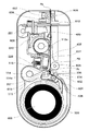
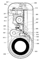
図3は、カートリッジ110が装着された状態における印刷装置100の縦断面図である。図3を用いて、印刷装置100が印刷動作の処理を行う際に動作する各部の構成について説明する。
FIG. 3 is a longitudinal sectional view of the
図3において、カートリッジ110に搬送路601が設けられる。カートリッジ110に内包されたロール紙409が、印画時に搬送路601を通過して印画位置P0まで引き出される。ここで印画位置P0は、サーマルヘッド227がプラテンローラ605との間でインクリボン407をロール紙409に圧接させる位置である。すなわち、サーマルヘッド227を、インクリボン407及びロール紙409を介してプラテンローラ605に圧接させる位置である。ローラ408に巻き回されていたロール紙409は、分離部材406により引き剥がされることで、カートリッジ出口602からカートリッジ110の外部に引き出され、搬送路601を通過する。
In FIG. 3, a
このほか、ピンチローラ613及びグリップローラ614が、ロール紙409を挟持する。デカール用ガイド603は、印刷時にロール紙409のカール方向とは逆の曲率を持たせるために設けられ、ロール紙409の巻き癖を矯正する。グリップローラ614が図3の時計回りに回転することで、カートリッジ110から送り出されたロール紙409が、印画位置P0に向かって搬送される。
In addition, the
サーマルヘッド227は、ヘッドレバー612に一体的に固定され、印刷装置100のベースフレームにヘッドレバー612を介して回動可能に配設されている。図3に示されるように、本実施の形態では、剥離板228はサーマルヘッド227と一体のサーマルユニットとして構成される。従って、剥離板228は、サーマルヘッド227と連動して一体に可動する。ヘッドアップダウンモータ219は、ヘッドレバー612を駆動してサーマルヘッド227を回動させる。
The
プラテンローラ605は、印画時に、印画位置P0においてサーマルヘッド227との間でインクリボン407とロール紙409とを重畳させた状態を維持する。排紙ローラ606は、ロール紙409を排紙方向に搬送する。排紙ローラ606と従動ローラ607とは、ロール紙409を介して対向する位置に配され、図示しない駆動機構により圧接・離間するようになっており、排紙時に圧接してロール紙409を挟持する。
The
カッター刃609とカッター受け刃610とは、ロール紙409の搬送路を挟んで対向した位置に配置され、また、カッター刃609を駆動するカッターモータ221及びギア列608が一体的に構成される。これらによってカッターユニットが構成される。カッターモータ221の動作はギア列608によってカッターユニットに伝達される。カッター刃609及びカッター受け刃610はギア列608により駆動され、はさみ状に上下の刃が摺り合わされることによりロール紙409を切断する。
The
ここで、排紙方向は、プラテンローラ605から見て排紙ローラ606及び従動ローラ607のある方向である。またロール紙409は、印画開始前には一旦排紙方向と同じ方向に搬送される。しかし、インクリボン407が供給ローラ113aから巻き取りローラ114aに巻き取られるときにインクリボン407が搬送される方向が、印画時におけるロール紙409の搬送方向となる。従って、プラテンローラ605から見て、印画時におけるロール紙409の搬送方向の下流側は、排紙される側とは反対の側となる。
Here, the paper discharge direction is a direction in which the
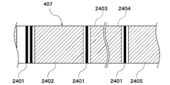
図4は、インクリボン407の一部分を示す図である。インクリボン407には、色材インク層として、イエロー層2402、マゼンタ層2403、シアン層2404が施され、さらにオーバーコート層2405が順に施される。各層の頭出し位置に、帯状にマーカー2401が塗布されている。マーカー2401は黒色の線である。イエロー層2402の先頭部分にはマーカー2401が2本塗布されており、他の層の先頭部分のマーカー2401は1本であることから、イエロー層2402の先頭部分が識別される。
FIG. 4 is a view showing a part of the
図3に示すように、リボン頭出しセンサ207は、ロール紙頭出しセンサ206よりも巻き取りローラ114a寄りの位置に配置される。インク頭出しセンサ207と対向する位置にはインクリボン407を挟んで反射シート115が貼られており、インク頭出しセンサ207から投光された光を反射シート115が反射するようになっている。リボン頭出しセンサ207は、反射シート115で反射した光がマーカー2401によって遮蔽されたことを検知する。そしてその検知結果がメインコントローラ201に送信され、メインコントローラ201は、現在、どの層が位置しているのかを識別できる。例えば、2本のマーカー2401が検知されたなら、最初に印画するイエロー層2402の頭出し位置であることを認識することができる。
As shown in FIG. 3, the
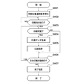
次に、印刷装置100における印刷処理の全体フローを説明する。図5は、印刷処理のフローチャートである。
Next, the overall flow of the printing process in the
印刷装置100にカートリッジ110が装着され、電源が投入された後、図3に示す状態となり、印刷対象となる画像データの取り込みが完了すると、図5に示す処理が開始される。
After the
ステップS801では、メインコントローラ201は、表示部102に表示された画像データの中から、操作部103を介してユーザにより印刷対象として選択された画像データに関する情報を受け付ける。ステップS802では、メインコントローラ201は、操作部103を介してユーザより印刷指示があったか否かを判別し、印刷指示があれば処理をステップS803に進める。
In step S <b> 801, the
ステップS803では、メインコントローラ201は、印刷可能か否かを判別する。ここでは、ステップS801において選択された画像データの全てが印刷可能であるか否かをロール紙409の残量に基づいて判別する。
In step S803, the
そして、印刷可能でない場合には、メインコントローラ201は、印刷不可である旨のメッセージを表示部102に表示させるとともに、処理をステップS806に進める。一方、印刷可能である場合には、メインコントローラ201は、選択された画像データに基づいて各色ごとの印画データを生成する(ステップS804)。
If printing is not possible, the
続くステップS805では、メインコントローラ201は、生成された印画データを用いて、後述する図6の印刷処理を行う。ステップS806では、メインコントローラ201は、印刷対象として選択された次の画像データがあるか否かを判別し、次の画像データがある場合には、メインコントローラ201は、処理をステップS803に戻して上記処理を繰り返す。一方、次の画像データがない場合は、メインコントローラ201は、処理をステップS807に進める。ステップS807では、メインコントローラ201は、終了処理を行い、図3に示す状態に戻す。
In the subsequent step S805, the
ここで、サーマルヘッド227が印画位置P0でプラテンローラ605との間でインクリボン407をロール紙409に圧接させるときにとるサーマルヘッド227の姿勢が印画姿勢である(図8参照)。一方、サーマルヘッド227がインクリボン407から離間し、インクリボン407をロール紙409に圧接させない姿勢が退避姿勢である(図7、図9、図10参照)。退避姿勢においては、サーマルヘッド227はプラテンローラ605から離間した位置にある。サーマルヘッド227は、回動動作によって、印画姿勢と退避姿勢との間を遷移することが可能である。
Here, the posture of the
また、剥離板228は、上記したようにサーマルヘッド227と連動して一体に移動動作をする。剥離板228は、サーマルヘッド227が印画姿勢、退避姿勢にあるとき、それぞれ「第1の姿勢」、「第2の姿勢」となる。剥離板228は、第1の姿勢において、所定位置Phにて、インクリボン407を介してロール紙409に対して圧接する(図8)。所定位置Phは、印画姿勢にあるサーマルヘッド227の発熱体の位置(印画位置P0に相当)に対して、印画時の搬送方向において所定距離だけ下流側に離間した位置である。一方、第2の姿勢においては、剥離板228はインクリボン407に当接するが、インクリボン407がロール紙409から離間するため、ロール紙409に対して圧接する状態とはならない(図7、図9、図10)。
Further, as described above, the peeling
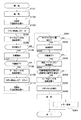
次に、図3、図6〜図10を用いて印刷処理時の印刷装置100の動作について以下説明する。図6は、図5のステップS805で実行される印刷処理のフローチャートである。図7、図8、図9、図10はそれぞれ、印刷装置100における印画開始状態、印画状態、排紙状態、排紙動作直後の状態を示す図である。
Next, the operation of the
まず、図6のステップS101では、メインコントローラ201は、ロール紙409をカートリッジ111から送り出して給紙するよう制御する。次に、ステップS102では、メインコントローラ201は、ロール紙409を印画開始位置まで搬送するよう制御して、印画開始状態にする(図7)。
First, in step S <b> 101 of FIG. 6, the
これらステップS101、S102で実行される給紙動作について説明する。図3に示す状態において、ロール紙409と一体的に回動するローラ408が図3の反時計回りに駆動されるとロール紙409が回転する。ロール紙409が回転することでロール紙保持フランジ503も回転し、ローラ408に巻き回されているロール紙409の先端部は、カートリッジ111の内周面に沿って進み、分離部材406ですくいあげられ、搬送路601へと押し出される。その結果、ロール紙409の先端部がカートリッジ出口602より送り出される。
The paper feeding operation executed in steps S101 and S102 will be described. In the state shown in FIG. 3, when the
カートリッジ出口602より送り出されたロール紙409は、グリップローラ614を通過する。ピンチローラ613はグリップローラ614に対して常に圧接状態であり、そのグリップ位置にロール紙409が誘い込まれることでグリップローラ614と共にロール紙409を挟持する。グリップローラ614の表面には、細かい突起状の爪が形成されており、ロール紙409の裏面へ噛み込むことでロール紙409がグリップされる。
The
グリップローラ614でグリップされたロール紙409はさらに搬送され、サーマルヘッド227とプラテンローラ605との間を通過する。グリップローラ614のプラテンローラ605寄りの位置にはロール紙頭出しセンサ206(図2)が配されており、ここをロール紙409の先端部が通過すると、ロール紙頭出しセンサ206がONになる。
The
メインコントローラ201は、ロール紙頭出しセンサ206のON信号を受信すると、印画サイズに応じた残りの用紙搬送量を算出する。この算出結果に基づいてロール紙搬送モータドライバ211(図2)を制御することにより、ギア列にて連結されたグリップローラ614を駆動する。ロール紙409はグリップローラ614により搬送され、印画開始位置に到達すると停止し、ロール紙409の頭出し完了となる(図7)。このようにして、一枚の画像を印刷するのに必要なロール紙409をカートリッジ111から引き出し、印画開始位置に搬送して待機する。
When the
次に、ステップS103では、メインコントローラ201はリボン頭出しを行う。すなわち、印画開始状態において、カートリッジ110に収納されているインクリボン407が巻き上げられる。インクリボン407は、リボン巻上げモータ217(図2)及びリボン巻上げモータ217に接続されたギア列を介して巻き取りローラ114aに巻き上げられる。
Next, in step S103, the
リボン頭出しセンサ207がインクリボン407のイエロー層2402の2本のマーカー2401を検知すると、メインコントローラ201はインクリボン巻上げモータ217を停止させる。以上により、リボン頭出しが行われる。このステップS103ではまた、メインコントローラ201は、後述するカウンタCTを「0」にリセットする。
When the
次に、ステップS104では、メインコントローラ201は、ヘッドアップダウンモータ219を制御してヘッドレバー612を駆動し、サーマルヘッド227を印画位置P0へ回動させる(図8)。これにより、サーマルヘッド227が退避姿勢から印画姿勢に遷移すると共に、剥離板228が第2の姿勢から第1の姿勢に遷移する。
Next, in step S104, the
本実施の形態では、メインコントローラ201は、毎回の印画動作を行う前に、その印画動作が色材インク層の転写であるかオーバーコート層の転写であるかを判定する。そして、その判定結果によって、当該印画動作直後におけるサーマルユニットの移動動作を制御する。
In the present embodiment, the
すなわち、ステップS105では、メインコントローラ201は、いずれかの色の色材インク層(2402〜2404)の転写であるか否かを判別する。そして色材インク層の転写でない場合は、ステップS201で、メインコントローラ201は、オーバーコート層2405の転写であるか否かを判別する。
That is, in step S105, the
上記したように、カウンタCTの値は、2本のマーカー2401で検知されイエロー層2402の頭出しがなされたことで0に設定されるが、その後はステップS109にて、マーカー2401が検知される毎に1ずつインクリメントされる。従って、メインコントローラ201は、カウンタCTの値によって、どの色の色材インク層の転写であるかも判別できる。具体的には、カウンタCT=0、1、2、3のとき、今回の印画がイエロー層2402、マゼンタ層2403、シアン層2404、オーバーコート層2405であると判別される。
As described above, the value of the counter CT is set to 0 by the detection of the two
ステップS105の判別の結果、次に印画されるものが色材インク層である場合は、メインコントローラ201は、処理をステップS106に進め、印画動作を実行する。すなわち、サーマルヘッド227が印画位置P0に到達した状態(図8)で、グリップローラ614により印画のためのロール紙409の搬送が開始される。ロール紙409の搬送が所定量行われ、搬送速度が一定になると、サーマルヘッド227に内蔵される発熱体が発熱駆動され、インクリボン407のイエロー層2402が昇華されてロール紙409に転写される。
If the result of the determination in step S105 is that the next material to be printed is a color material ink layer, the
次に、ステップS107で、メインコントローラ201は、今回の印画が終了したか否かを判別する。そして、今回の印画が終了した場合は、メインコントローラ201は、処理をステップS108に進める。ステップS108では、メインコントローラ201は、直ちに、ヘッドアップダウンモータ219を制御してヘッドレバー612を回動させる。それによって、ヘッドレバー612と一体的に固定されているサーマルヘッド227を印画姿勢の位置から退避姿勢の位置に退避移動させる。剥離板228はサーマルヘッド227と一体に移動するので、第1の姿勢から第2の姿勢に遷移することになる。
Next, in step S107, the
ここで、印画が終了した場合とは、転写時(印画時)における搬送方向に搬送されるロール紙409の印画領域の終端位置Pe(転写完了位置)(図7等)が印画位置P0に達した場合である。従って、色材インク層の転写の直後、サーマルヘッド227を直ちに退避移動させる。すなわち、ロール紙409の印画領域の終端位置Peが印画位置P0に到達した後であって所定位置Phを過ぎる前にサーマルヘッド227を印画姿勢から退避姿勢に遷移させることになる。すなわち、メインコントローラ201は、色材インク層の転写完了時には、転写完了のタイミングでサーマルヘッド227及び剥離板228を退避位置へ移動させることになる。
Here, when the printing is completed, the end position Pe (transfer completion position) (FIG. 7 and the like) of the printing area of the
これにより、ロール紙409からインクリボン407の色材インク層の剥離が速やかになされるので、印画領域外の部分への後端尾引の発生を抑制することができる。
As a result, the color material ink layer of the
次に、ステップS109では、メインコントローラ201は、次のリボン頭出しを行う。すなわち、インクリボン407を巻き上げ、リボン頭出しセンサ207において次のマーカー2401を検知すると、インクリボン巻上げモータ217を停止することで、インクリボン407の頭出しを行う。それと同時にカウンタCTを1だけインクリメントする。例えば、イエロー層2402の直後であれば、マゼンタ層2403のマーカー2401が検知され、マゼンタ層2403のリボン頭出し動作を経てイエロー層2402の印画が完了し、カウンタCTは「1」となる。
Next, in step S109, the
次に、ステップS110では、メインコントローラ201は、ロール紙409を印画開始位置まで搬送するよう制御して、再び印画開始状態にし(図7)、処理をステップS104に戻す。このように、ステップS104〜S110を繰り返すことで、イエロー層2402、マゼンタ層2403、シアン層2404の印画が順次実行される。そして、3色目のシアン層2404の印画終了後のステップS105では、カウンタCTの値が3になっているので、メインコントローラ201は、色材インク層の転写ではないと判別する。そして、メインコントローラ201は、オーバーコート層2405の転写であるか否かを判別する(ステップS201)。
Next, in step S110, the
そして、メインコントローラ201は、カウンタCTの値が3となっていればオーバーコート層2405の転写であると判別し、処理をステップS202に進める。ただし、カウンタCTが想定外の値である等、何らかの異常によりオーバーコート層2405の転写と判別できないときは、処理をステップS301に進める。その場合は、メインコントローラ201は、エラー表示処理を行い、図6の処理を終了させる。
If the value of the counter CT is 3, the
ステップS202では、メインコントローラ201はオーバーコート層2405の印画動作を実行する。すなわち、サーマルヘッド227が印画位置P0に到達した状態で、グリップローラ614により印画のためのロール紙409の搬送が開始される。ロール紙409の搬送が所定量行われ、搬送速度が一定になると、サーマルヘッド227に内蔵される発熱体が発熱駆動され、インクリボン407のオーバーコート層2405がロール紙409に転写される。
In step S202, the
次に、ステップS203で、メインコントローラ201は、今回の印画が終了したか否かを判別する。そして、今回の印画が終了した場合は、メインコントローラ201は、処理をステップS204に進める。ステップS204では、メインコントローラ201は、サーマルヘッド227の発熱駆動を停止させるが、サーマルヘッド227は印画姿勢に保ちながら、ロール紙409とインクリボン407の搬送を続行する。
Next, in step S203, the
次に、ステップS205では、メインコントローラ201は、印画時の搬送方向において、ロール紙409の印画領域の終端位置Peが、剥離板228の位置でもある所定位置Phを通過したか否かを判別する。ここで、終端位置Peが所定位置Phを通過したか否かは、例えば、印画範囲識別センサ210の検知結果から判別される。
Next, in step S205, the
印画範囲識別センサ210は、図3等に図示していないが、所定位置Phに相当する位置に配置される。印画範囲識別センサ210は、印画のためのロール紙409の搬送方向において、終端位置Peが所定位置Phを通過したことを検知する。印画範囲識別センサ210としては光学式が考えられるが、構成は問わない。
Although not shown in FIG. 3 or the like, the print
なお、終端位置Peは、ロール紙409の排紙方向先端部としたが、これに限られない。例えば、先端部よりマージンを確保した位置としてもよく、それに応じて印画範囲識別センサ210の配置位置も設定する。また、上述したように、メインコントローラ201は、ロール紙頭出しセンサ206のON信号を受信した後の用紙搬送量を算出で求めている。そこで、当該算出値を記憶しておき、この算出値と印画時の搬送方向へのロール紙409の搬送量とから、終端位置Peが所定位置Phを通過したことを判別するようにしてもよい。この場合、印画範囲識別センサ210を用いる必要はない。
The end position Pe is the leading end of the
ステップS205の判別の結果、メインコントローラ201は、印画領域の終端位置Peが所定位置Phを通過した場合は、処理をステップS206に進める。ステップS206では、メインコントローラ201は、前記ステップS108と同様に、ヘッドアップダウンモータ219を制御してヘッドレバー612を回動させ、サーマルヘッド227を退避姿勢に遷移させる。剥離板228は第1の姿勢から第2の姿勢に遷移することになる。すなわち、メインコントローラ201は、オーバーコート層2405の転写完了時には、転写完了から所定のタイミングが経過した後にサーマルヘッド227及び剥離板228を退避位置へ移動させることになる。
As a result of the determination in step S205, the
これにより、オーバーコート層2405の印画終了後、オーバーコート層2405の温度低下の時間を適切に確保してから、ロール紙409からインクリボン407のオーバーコート層2405の剥離がなされる。従って、オーバーコート層2405の転写領域とそれ以外の領域とで、ロール紙409との接着状態の差異が明確になってから剥離がなされるので、オーバーコート層2405の箔切れ不良の発生を抑制することができる。
As a result, after the printing of the
次に、ステップS207で、メインコントローラ201は、インクリボン407を微小量だけ供給ローラ113a側に巻き上げ、インクリボン407のたるみを取る。以上により、イエロー、マゼンタ、シアン、オーバーコート層の順にインクが重ねられて転写される印画動作が完了する。
Next, in step S207, the
次に、ステップS208では、メインコントローラ201は、排紙動作を実行する。すなわち、図9に示すように、ロール紙409が排紙方向へ搬送される。この時、ロール紙409は印画領域と未印画領域との境界がカッターユニットの切断位置にくるように搬送される。
Next, in step S208, the
グリップローラ614とピンチローラ613はロール紙409を狭持したままの状態であり、グリップローラ614を所定量回転させることでロール紙409を所定量搬送する。カッターユニットのカッターモータ221が駆動されると、カッター刃609及びカッター受け刃610によってロール紙409が切断される。
The
カット処理により先端部が切断された印画済みのロール紙409は、排紙ローラ606によりグリップされた状態にある。この状態から、排紙ローラ606が駆動され、ロール紙409は排紙方向に搬送される。ここで、ロール収納部側のロール紙409の先端は排紙時の紙送りと同時に排紙方向に前進する。その結果、印画済みのロール紙409は排紙ローラ606により排紙方向に送られた後、上流側から来た未印画のロール紙409の先端部に押し出されて印刷装置100の外に排出される。
The printed
排紙動作の処理後、メインコントローラ201は、図5のステップS805で、終了処理を行う。終了処理では、ロール紙巻き戻し処理を行う。排紙動作完了後は、ロール紙409は図10に示すように引き出された状態になっている。次の印画を行わない場合は、ロール紙409がカートリッジ111内に完全に収納されてカートリッジ111が着脱可能な状態になっていなければならない。そのため、ロール紙409の巻き取り動作を行う。
After processing the paper discharge operation, the
ロール紙409の巻き取り動作は、グリップローラ614とローラ408とを、用紙供給時とは逆方向に回転させることで行われる。ロール紙409の巻き取り中にはロール紙409の頭出しで使用したロール紙頭出しセンサ206を使用する。ロール紙有りの状態から無しの状態に変わるところを起点に所定量だけグリップローラ614及びローラ408を追加駆動することで、精度よくロール紙409をカートリッジ111に収納できるようにしている。
The winding operation of the
本実施の形態によれば、色材インク層の転写の直後においては、ロール紙409の印画領域の終端位置Peが所定位置Phを過ぎる前に、サーマルヘッド227が印画姿勢から退避姿勢に遷移すると共に剥離板228が第1の姿勢から第2の姿勢に遷移する。一方、オーバーコート層2405の転写の直後においては、終端位置Peが所定位置Phを過ぎてから、サーマルヘッド227が印画姿勢から退避姿勢に遷移すると共に剥離板228が第1の姿勢から第2の姿勢に遷移する。
According to the present embodiment, immediately after the transfer of the color material ink layer, the
すなわち、メインコントローラ201は、オーバーコート層2405の転写完了後もロール紙409及びインクリボン407を搬送させるよう制御する。そして、ロール紙409及びインクリボン407の転写完了位置が剥離板228の位置へ搬送されたタイミングで、サーマルヘッド227及び剥離板228を退避位置に移動させるよう制御する。
That is, the
従って、転写がオーバーコート層2405であった場合は、色材インク層であった場合に対し、サーマルユニットの退避のタイミングを遅らせる。これにより、色材インク層の転写直後は速やかに剥離がなされる一方、オーバーコート層の転写終了後は適切な時間をとってから剥離がなされる。よって、簡単な制御で高い画像品質を維持することができる。
Therefore, when the transfer is the
また、サーマルヘッド227と剥離板228とは一体に構成されているので、構成が簡単で、装置の小型化や低コスト化に有利である。
Further, since the
なお、サーマルヘッド227と剥離板228とが一体でない構成であっても、動作のタイミングをそれぞれ制御すれば、高い画像品質を維持することは可能である。すなわち、上記のようにサーマルヘッド227が印画姿勢と退避姿勢とに遷移するのにリンクさせて、剥離板228が第1の姿勢と第2の姿勢とに遷移するよう制御すればよい。
Even if the
以上、本発明の好ましい実施形態について説明したが、本発明はこれらの実施形態に限定されず、その要旨の範囲内で種々の変形及び変更が可能である。 As mentioned above, although preferable embodiment of this invention was described, this invention is not limited to these embodiment, A various deformation | transformation and change are possible within the range of the summary.
201 メインコントローラ
227 サーマルヘッド
228 剥離板
407 インクリボン
409 ロール紙
605 プラテンローラ
2402〜2404 色材インク層
2405 オーバーコート層
Pe 終端位置
Ph 所定位置
201
Claims (4)
サーマルヘッドにより前記記録用紙に前記インクリボンの前記色インクを転写させ、前記色インクの転写後に、前記サーマルヘッドにより前記色インクが転写された記録用紙に前記オーバーコートを転写させる印刷制御手段と、
前記サーマルヘッドを、前記インクリボンおよび前記記録用紙を介してプラテンローラに圧接させる印画位置と前記プラテンローラから離間させる退避位置との間を移動させるための移動手段と、
前記サーマルヘッドと連動して移動し、前記サーマルヘッドによる転写後の前記インクリボンを前記記録用紙から剥離するための剥離部材と、を有し、
前記移動手段は、前記色インクの転写完了の際には、前記色インクの転写完了のタイミングで前記サーマルヘッドおよび前記剥離部材を前記印画位置から前記退避位置に移動させ、前記オーバーコートの転写完了の際には、前記サーマルヘッドの発熱を停止して前記サーマルヘッドを前記印画位置に保って、前記オーバーコートの転写が完了した後、所定のタイミングが経過すると前記サーマルヘッドおよび前記剥離板を退避位置に移動させることを特徴とするサーマルプリンタ。 A thermal printer that prints on recording paper using an ink ribbon in which color ink and overcoat are formed in order,
Print control means for transferring the color ink of the ink ribbon to the recording paper by a thermal head, and transferring the overcoat to the recording paper to which the color ink has been transferred by the thermal head after the transfer of the color ink;
Moving means for moving the thermal head between a printing position where the thermal head is pressed against the platen roller via the ink ribbon and the recording paper and a retracted position where the thermal head is separated from the platen roller;
A separation member for moving in conjunction with the thermal head, for separating the ink ribbon after the transfer by the thermal head from the recording paper,
When the transfer of the color ink is completed, the moving unit moves the thermal head and the peeling member from the print position to the retracted position at the completion timing of the transfer of the color ink, and the transfer of the overcoat is completed. In this case, after the heat transfer of the thermal head is stopped and the thermal head is kept at the printing position and the transfer of the overcoat is completed, the thermal head and the release plate are retracted when a predetermined timing elapses. A thermal printer characterized by being moved to a position .
前記オーバーコートの転写の際において、前記搬送手段は、前記オーバーコートの転写完了後も前記記録用紙および前記インクリボンを搬送し、前記移動手段は、前記記録用紙および前記インクリボンの転写完了位置が前記剥離部材の位置に搬送されたタイミングで、前記サーマルヘッドおよび前記剥離部材を前記退避位置に移動させることを特徴とする請求項3に記載のサーマルプリンタ。 Furthermore, when transferring the color ink and the overcoat by the thermal head, it has transport means for transporting the recording paper and the ink ribbon, respectively .
In case of transfer of the overcoat, the conveying means, even after the transfer completion of the overcoat to convey the recording sheet and the ink ribbon, the moving means, the transfer completion position of the recording paper and the ink ribbon The thermal printer according to claim 3, wherein the thermal head and the peeling member are moved to the retracted position at a timing when the thermal head and the peeling member are conveyed to the position of the peeling member.
Priority Applications (1)
| Application Number | Priority Date | Filing Date | Title |
|---|---|---|---|
| JP2011109434A JP5843476B2 (en) | 2011-05-16 | 2011-05-16 | Thermal printer |
Applications Claiming Priority (1)
| Application Number | Priority Date | Filing Date | Title |
|---|---|---|---|
| JP2011109434A JP5843476B2 (en) | 2011-05-16 | 2011-05-16 | Thermal printer |
Publications (3)
| Publication Number | Publication Date |
|---|---|
| JP2012240227A JP2012240227A (en) | 2012-12-10 |
| JP2012240227A5 JP2012240227A5 (en) | 2014-06-19 |
| JP5843476B2 true JP5843476B2 (en) | 2016-01-13 |
Family
ID=47462442
Family Applications (1)
| Application Number | Title | Priority Date | Filing Date |
|---|---|---|---|
| JP2011109434A Expired - Fee Related JP5843476B2 (en) | 2011-05-16 | 2011-05-16 | Thermal printer |
Country Status (1)
| Country | Link |
|---|---|
| JP (1) | JP5843476B2 (en) |
Families Citing this family (1)
| Publication number | Priority date | Publication date | Assignee | Title |
|---|---|---|---|---|
| JP6926730B2 (en) * | 2017-06-30 | 2021-08-25 | 大日本印刷株式会社 | Thermal transfer printing device and thermal transfer printing method |
Family Cites Families (5)
| Publication number | Priority date | Publication date | Assignee | Title |
|---|---|---|---|---|
| JP2516907B2 (en) * | 1985-10-08 | 1996-07-24 | キヤノン株式会社 | Serial type thermal transfer recording device |
| JPH11129512A (en) * | 1997-10-31 | 1999-05-18 | Victor Co Of Japan Ltd | Thermal transfer printer |
| JPH11263033A (en) * | 1998-03-18 | 1999-09-28 | Victor Co Of Japan Ltd | Thermal transfer printer |
| JP4039106B2 (en) * | 2002-04-23 | 2008-01-30 | ブラザー工業株式会社 | Sublimation type thermal transfer printer |
| JP4984249B2 (en) * | 2007-09-27 | 2012-07-25 | 大日本印刷株式会社 | Intermediate transfer recording medium |
-
2011
- 2011-05-16 JP JP2011109434A patent/JP5843476B2/en not_active Expired - Fee Related
Also Published As
| Publication number | Publication date |
|---|---|
| JP2012240227A (en) | 2012-12-10 |
Similar Documents
| Publication | Publication Date | Title |
|---|---|---|
| JP4906762B2 (en) | Printing apparatus and printing apparatus control method | |
| EP2896505B1 (en) | Thermal printer | |
| JP2011020769A (en) | Sheet conveyance mechanism, recording apparatus having this conveyance mechanism and sheet conveyance method | |
| JP5110926B2 (en) | cartridge | |
| JP5981767B2 (en) | Image forming apparatus, control method therefor, program, and storage medium | |
| JP3736449B2 (en) | Printer | |
| JP2009202419A (en) | Printing apparatus and its control method | |
| JP5843476B2 (en) | Thermal printer | |
| US8456500B2 (en) | Printing apparatus and method for controlling printing apparatus | |
| JP6366402B2 (en) | Thermal printer | |
| JP2008229894A (en) | Printing device and control method thereof | |
| US8770870B2 (en) | Printer with ribbon marker detection control | |
| JP2010110929A (en) | Thermal printer, control method for the same, and program | |
| JP2004209808A (en) | Printer and method of controlling the same | |
| JP5139819B2 (en) | Cartridges and printers | |
| JP6463088B2 (en) | Printing apparatus and printing apparatus control method | |
| JP5693033B2 (en) | Printing device | |
| WO2017169249A1 (en) | Printing device, printing system, printing method, and recording medium | |
| WO2017169401A1 (en) | Printer | |
| JP3941106B2 (en) | Printing tape and tape printer | |
| US11890884B2 (en) | Printer device | |
| US20240123746A1 (en) | Printer device | |
| JP5235703B2 (en) | Printing device | |
| JP5838627B2 (en) | Tape printer | |
| JP2014087979A (en) | Printing device and control method for the same |
Legal Events
| Date | Code | Title | Description |
|---|---|---|---|
| A521 | Request for written amendment filed |
Free format text: JAPANESE INTERMEDIATE CODE: A523 Effective date: 20140430 |
|
| A621 | Written request for application examination |
Free format text: JAPANESE INTERMEDIATE CODE: A621 Effective date: 20140430 |
|
| A977 | Report on retrieval |
Free format text: JAPANESE INTERMEDIATE CODE: A971007 Effective date: 20150309 |
|
| A131 | Notification of reasons for refusal |
Free format text: JAPANESE INTERMEDIATE CODE: A131 Effective date: 20150317 |
|
| A521 | Request for written amendment filed |
Free format text: JAPANESE INTERMEDIATE CODE: A523 Effective date: 20150515 |
|
| TRDD | Decision of grant or rejection written | ||
| A01 | Written decision to grant a patent or to grant a registration (utility model) |
Free format text: JAPANESE INTERMEDIATE CODE: A01 Effective date: 20151020 |
|
| A61 | First payment of annual fees (during grant procedure) |
Free format text: JAPANESE INTERMEDIATE CODE: A61 Effective date: 20151117 |
|
| R151 | Written notification of patent or utility model registration |
Ref document number: 5843476 Country of ref document: JP Free format text: JAPANESE INTERMEDIATE CODE: R151 |
|
| LAPS | Cancellation because of no payment of annual fees |