JP5841530B2 - Vehicle performance control system and method - Google Patents
Vehicle performance control system and method Download PDFInfo
- Publication number
- JP5841530B2 JP5841530B2 JP2012520648A JP2012520648A JP5841530B2 JP 5841530 B2 JP5841530 B2 JP 5841530B2 JP 2012520648 A JP2012520648 A JP 2012520648A JP 2012520648 A JP2012520648 A JP 2012520648A JP 5841530 B2 JP5841530 B2 JP 5841530B2
- Authority
- JP
- Japan
- Prior art keywords
- vehicle
- weight
- power
- speed
- total
- Prior art date
- Legal status (The legal status is an assumption and is not a legal conclusion. Google has not performed a legal analysis and makes no representation as to the accuracy of the status listed.)
- Active
Links
- 238000000034 method Methods 0.000 title claims description 18
- 239000006096 absorbing agent Substances 0.000 claims description 3
- 230000000694 effects Effects 0.000 description 12
- 238000005065 mining Methods 0.000 description 6
- 230000001133 acceleration Effects 0.000 description 2
- 230000002411 adverse Effects 0.000 description 2
- 238000002485 combustion reaction Methods 0.000 description 2
- 238000004891 communication Methods 0.000 description 2
- 239000000446 fuel Substances 0.000 description 2
- 238000012423 maintenance Methods 0.000 description 2
- 230000009467 reduction Effects 0.000 description 2
- 238000006243 chemical reaction Methods 0.000 description 1
- 238000010586 diagram Methods 0.000 description 1
- 230000006872 improvement Effects 0.000 description 1
- 238000004519 manufacturing process Methods 0.000 description 1
- 238000005259 measurement Methods 0.000 description 1
- 238000012986 modification Methods 0.000 description 1
- 230000004048 modification Effects 0.000 description 1
- 238000010248 power generation Methods 0.000 description 1
- 230000008569 process Effects 0.000 description 1
- 238000011084 recovery Methods 0.000 description 1
- 230000008929 regeneration Effects 0.000 description 1
- 238000011069 regeneration method Methods 0.000 description 1
- 239000000725 suspension Substances 0.000 description 1
Images

Classifications
-
- B—PERFORMING OPERATIONS; TRANSPORTING
- B60—VEHICLES IN GENERAL
- B60K—ARRANGEMENT OR MOUNTING OF PROPULSION UNITS OR OF TRANSMISSIONS IN VEHICLES; ARRANGEMENT OR MOUNTING OF PLURAL DIVERSE PRIME-MOVERS IN VEHICLES; AUXILIARY DRIVES FOR VEHICLES; INSTRUMENTATION OR DASHBOARDS FOR VEHICLES; ARRANGEMENTS IN CONNECTION WITH COOLING, AIR INTAKE, GAS EXHAUST OR FUEL SUPPLY OF PROPULSION UNITS IN VEHICLES
- B60K6/00—Arrangement or mounting of plural diverse prime-movers for mutual or common propulsion, e.g. hybrid propulsion systems comprising electric motors and internal combustion engines ; Control systems therefor, i.e. systems controlling two or more prime movers, or controlling one of these prime movers and any of the transmission, drive or drive units Informative references: mechanical gearings with secondary electric drive F16H3/72; arrangements for handling mechanical energy structurally associated with the dynamo-electric machine H02K7/00; machines comprising structurally interrelated motor and generator parts H02K51/00; dynamo-electric machines not otherwise provided for in H02K see H02K99/00
- B60K6/20—Arrangement or mounting of plural diverse prime-movers for mutual or common propulsion, e.g. hybrid propulsion systems comprising electric motors and internal combustion engines ; Control systems therefor, i.e. systems controlling two or more prime movers, or controlling one of these prime movers and any of the transmission, drive or drive units Informative references: mechanical gearings with secondary electric drive F16H3/72; arrangements for handling mechanical energy structurally associated with the dynamo-electric machine H02K7/00; machines comprising structurally interrelated motor and generator parts H02K51/00; dynamo-electric machines not otherwise provided for in H02K see H02K99/00 the prime-movers consisting of electric motors and internal combustion engines, e.g. HEVs
- B60K6/42—Arrangement or mounting of plural diverse prime-movers for mutual or common propulsion, e.g. hybrid propulsion systems comprising electric motors and internal combustion engines ; Control systems therefor, i.e. systems controlling two or more prime movers, or controlling one of these prime movers and any of the transmission, drive or drive units Informative references: mechanical gearings with secondary electric drive F16H3/72; arrangements for handling mechanical energy structurally associated with the dynamo-electric machine H02K7/00; machines comprising structurally interrelated motor and generator parts H02K51/00; dynamo-electric machines not otherwise provided for in H02K see H02K99/00 the prime-movers consisting of electric motors and internal combustion engines, e.g. HEVs characterised by the architecture of the hybrid electric vehicle
- B60K6/46—Series type
-
- B—PERFORMING OPERATIONS; TRANSPORTING
- B60—VEHICLES IN GENERAL
- B60L—PROPULSION OF ELECTRICALLY-PROPELLED VEHICLES; SUPPLYING ELECTRIC POWER FOR AUXILIARY EQUIPMENT OF ELECTRICALLY-PROPELLED VEHICLES; ELECTRODYNAMIC BRAKE SYSTEMS FOR VEHICLES IN GENERAL; MAGNETIC SUSPENSION OR LEVITATION FOR VEHICLES; MONITORING OPERATING VARIABLES OF ELECTRICALLY-PROPELLED VEHICLES; ELECTRIC SAFETY DEVICES FOR ELECTRICALLY-PROPELLED VEHICLES
- B60L15/00—Methods, circuits, or devices for controlling the traction-motor speed of electrically-propelled vehicles
- B60L15/20—Methods, circuits, or devices for controlling the traction-motor speed of electrically-propelled vehicles for control of the vehicle or its driving motor to achieve a desired performance, e.g. speed, torque, programmed variation of speed
-
- B—PERFORMING OPERATIONS; TRANSPORTING
- B60—VEHICLES IN GENERAL
- B60L—PROPULSION OF ELECTRICALLY-PROPELLED VEHICLES; SUPPLYING ELECTRIC POWER FOR AUXILIARY EQUIPMENT OF ELECTRICALLY-PROPELLED VEHICLES; ELECTRODYNAMIC BRAKE SYSTEMS FOR VEHICLES IN GENERAL; MAGNETIC SUSPENSION OR LEVITATION FOR VEHICLES; MONITORING OPERATING VARIABLES OF ELECTRICALLY-PROPELLED VEHICLES; ELECTRIC SAFETY DEVICES FOR ELECTRICALLY-PROPELLED VEHICLES
- B60L50/00—Electric propulsion with power supplied within the vehicle
- B60L50/10—Electric propulsion with power supplied within the vehicle using propulsion power supplied by engine-driven generators, e.g. generators driven by combustion engines
-
- B—PERFORMING OPERATIONS; TRANSPORTING
- B60—VEHICLES IN GENERAL
- B60T—VEHICLE BRAKE CONTROL SYSTEMS OR PARTS THEREOF; BRAKE CONTROL SYSTEMS OR PARTS THEREOF, IN GENERAL; ARRANGEMENT OF BRAKING ELEMENTS ON VEHICLES IN GENERAL; PORTABLE DEVICES FOR PREVENTING UNWANTED MOVEMENT OF VEHICLES; VEHICLE MODIFICATIONS TO FACILITATE COOLING OF BRAKES
- B60T8/00—Arrangements for adjusting wheel-braking force to meet varying vehicular or ground-surface conditions, e.g. limiting or varying distribution of braking force
- B60T8/17—Using electrical or electronic regulation means to control braking
- B60T8/172—Determining control parameters used in the regulation, e.g. by calculations involving measured or detected parameters
-
- B—PERFORMING OPERATIONS; TRANSPORTING
- B60—VEHICLES IN GENERAL
- B60T—VEHICLE BRAKE CONTROL SYSTEMS OR PARTS THEREOF; BRAKE CONTROL SYSTEMS OR PARTS THEREOF, IN GENERAL; ARRANGEMENT OF BRAKING ELEMENTS ON VEHICLES IN GENERAL; PORTABLE DEVICES FOR PREVENTING UNWANTED MOVEMENT OF VEHICLES; VEHICLE MODIFICATIONS TO FACILITATE COOLING OF BRAKES
- B60T8/00—Arrangements for adjusting wheel-braking force to meet varying vehicular or ground-surface conditions, e.g. limiting or varying distribution of braking force
- B60T8/18—Arrangements for adjusting wheel-braking force to meet varying vehicular or ground-surface conditions, e.g. limiting or varying distribution of braking force responsive to vehicle weight or load, e.g. load distribution
-
- B—PERFORMING OPERATIONS; TRANSPORTING
- B60—VEHICLES IN GENERAL
- B60W—CONJOINT CONTROL OF VEHICLE SUB-UNITS OF DIFFERENT TYPE OR DIFFERENT FUNCTION; CONTROL SYSTEMS SPECIALLY ADAPTED FOR HYBRID VEHICLES; ROAD VEHICLE DRIVE CONTROL SYSTEMS FOR PURPOSES NOT RELATED TO THE CONTROL OF A PARTICULAR SUB-UNIT
- B60W30/00—Purposes of road vehicle drive control systems not related to the control of a particular sub-unit, e.g. of systems using conjoint control of vehicle sub-units, or advanced driver assistance systems for ensuring comfort, stability and safety or drive control systems for propelling or retarding the vehicle
- B60W30/18—Propelling the vehicle
- B60W30/188—Controlling power parameters of the driveline, e.g. determining the required power
- B60W30/1882—Controlling power parameters of the driveline, e.g. determining the required power characterised by the working point of the engine, e.g. by using engine output chart
-
- B—PERFORMING OPERATIONS; TRANSPORTING
- B60—VEHICLES IN GENERAL
- B60L—PROPULSION OF ELECTRICALLY-PROPELLED VEHICLES; SUPPLYING ELECTRIC POWER FOR AUXILIARY EQUIPMENT OF ELECTRICALLY-PROPELLED VEHICLES; ELECTRODYNAMIC BRAKE SYSTEMS FOR VEHICLES IN GENERAL; MAGNETIC SUSPENSION OR LEVITATION FOR VEHICLES; MONITORING OPERATING VARIABLES OF ELECTRICALLY-PROPELLED VEHICLES; ELECTRIC SAFETY DEVICES FOR ELECTRICALLY-PROPELLED VEHICLES
- B60L2200/00—Type of vehicles
- B60L2200/26—Rail vehicles
-
- B—PERFORMING OPERATIONS; TRANSPORTING
- B60—VEHICLES IN GENERAL
- B60L—PROPULSION OF ELECTRICALLY-PROPELLED VEHICLES; SUPPLYING ELECTRIC POWER FOR AUXILIARY EQUIPMENT OF ELECTRICALLY-PROPELLED VEHICLES; ELECTRODYNAMIC BRAKE SYSTEMS FOR VEHICLES IN GENERAL; MAGNETIC SUSPENSION OR LEVITATION FOR VEHICLES; MONITORING OPERATING VARIABLES OF ELECTRICALLY-PROPELLED VEHICLES; ELECTRIC SAFETY DEVICES FOR ELECTRICALLY-PROPELLED VEHICLES
- B60L2210/00—Converter types
- B60L2210/20—AC to AC converters
-
- B—PERFORMING OPERATIONS; TRANSPORTING
- B60—VEHICLES IN GENERAL
- B60L—PROPULSION OF ELECTRICALLY-PROPELLED VEHICLES; SUPPLYING ELECTRIC POWER FOR AUXILIARY EQUIPMENT OF ELECTRICALLY-PROPELLED VEHICLES; ELECTRODYNAMIC BRAKE SYSTEMS FOR VEHICLES IN GENERAL; MAGNETIC SUSPENSION OR LEVITATION FOR VEHICLES; MONITORING OPERATING VARIABLES OF ELECTRICALLY-PROPELLED VEHICLES; ELECTRIC SAFETY DEVICES FOR ELECTRICALLY-PROPELLED VEHICLES
- B60L2240/00—Control parameters of input or output; Target parameters
- B60L2240/10—Vehicle control parameters
- B60L2240/26—Vehicle weight
-
- B—PERFORMING OPERATIONS; TRANSPORTING
- B60—VEHICLES IN GENERAL
- B60L—PROPULSION OF ELECTRICALLY-PROPELLED VEHICLES; SUPPLYING ELECTRIC POWER FOR AUXILIARY EQUIPMENT OF ELECTRICALLY-PROPELLED VEHICLES; ELECTRODYNAMIC BRAKE SYSTEMS FOR VEHICLES IN GENERAL; MAGNETIC SUSPENSION OR LEVITATION FOR VEHICLES; MONITORING OPERATING VARIABLES OF ELECTRICALLY-PROPELLED VEHICLES; ELECTRIC SAFETY DEVICES FOR ELECTRICALLY-PROPELLED VEHICLES
- B60L2240/00—Control parameters of input or output; Target parameters
- B60L2240/40—Drive Train control parameters
- B60L2240/48—Drive Train control parameters related to transmissions
- B60L2240/486—Operating parameters
-
- B—PERFORMING OPERATIONS; TRANSPORTING
- B60—VEHICLES IN GENERAL
- B60W—CONJOINT CONTROL OF VEHICLE SUB-UNITS OF DIFFERENT TYPE OR DIFFERENT FUNCTION; CONTROL SYSTEMS SPECIALLY ADAPTED FOR HYBRID VEHICLES; ROAD VEHICLE DRIVE CONTROL SYSTEMS FOR PURPOSES NOT RELATED TO THE CONTROL OF A PARTICULAR SUB-UNIT
- B60W2530/00—Input parameters relating to vehicle conditions or values, not covered by groups B60W2510/00 or B60W2520/00
- B60W2530/10—Weight
-
- B—PERFORMING OPERATIONS; TRANSPORTING
- B60—VEHICLES IN GENERAL
- B60W—CONJOINT CONTROL OF VEHICLE SUB-UNITS OF DIFFERENT TYPE OR DIFFERENT FUNCTION; CONTROL SYSTEMS SPECIALLY ADAPTED FOR HYBRID VEHICLES; ROAD VEHICLE DRIVE CONTROL SYSTEMS FOR PURPOSES NOT RELATED TO THE CONTROL OF A PARTICULAR SUB-UNIT
- B60W2710/00—Output or target parameters relating to a particular sub-units
- B60W2710/10—Change speed gearings
- B60W2710/105—Output torque
-
- B—PERFORMING OPERATIONS; TRANSPORTING
- B60—VEHICLES IN GENERAL
- B60Y—INDEXING SCHEME RELATING TO ASPECTS CROSS-CUTTING VEHICLE TECHNOLOGY
- B60Y2200/00—Type of vehicle
- B60Y2200/10—Road Vehicles
- B60Y2200/14—Trucks; Load vehicles, Busses
-
- B—PERFORMING OPERATIONS; TRANSPORTING
- B60—VEHICLES IN GENERAL
- B60Y—INDEXING SCHEME RELATING TO ASPECTS CROSS-CUTTING VEHICLE TECHNOLOGY
- B60Y2200/00—Type of vehicle
- B60Y2200/10—Road Vehicles
- B60Y2200/14—Trucks; Load vehicles, Busses
- B60Y2200/145—Haulage vehicles, trailing trucks
-
- Y—GENERAL TAGGING OF NEW TECHNOLOGICAL DEVELOPMENTS; GENERAL TAGGING OF CROSS-SECTIONAL TECHNOLOGIES SPANNING OVER SEVERAL SECTIONS OF THE IPC; TECHNICAL SUBJECTS COVERED BY FORMER USPC CROSS-REFERENCE ART COLLECTIONS [XRACs] AND DIGESTS
- Y02—TECHNOLOGIES OR APPLICATIONS FOR MITIGATION OR ADAPTATION AGAINST CLIMATE CHANGE
- Y02T—CLIMATE CHANGE MITIGATION TECHNOLOGIES RELATED TO TRANSPORTATION
- Y02T10/00—Road transport of goods or passengers
- Y02T10/60—Other road transportation technologies with climate change mitigation effect
- Y02T10/62—Hybrid vehicles
-
- Y—GENERAL TAGGING OF NEW TECHNOLOGICAL DEVELOPMENTS; GENERAL TAGGING OF CROSS-SECTIONAL TECHNOLOGIES SPANNING OVER SEVERAL SECTIONS OF THE IPC; TECHNICAL SUBJECTS COVERED BY FORMER USPC CROSS-REFERENCE ART COLLECTIONS [XRACs] AND DIGESTS
- Y02—TECHNOLOGIES OR APPLICATIONS FOR MITIGATION OR ADAPTATION AGAINST CLIMATE CHANGE
- Y02T—CLIMATE CHANGE MITIGATION TECHNOLOGIES RELATED TO TRANSPORTATION
- Y02T10/00—Road transport of goods or passengers
- Y02T10/60—Other road transportation technologies with climate change mitigation effect
- Y02T10/64—Electric machine technologies in electromobility
-
- Y—GENERAL TAGGING OF NEW TECHNOLOGICAL DEVELOPMENTS; GENERAL TAGGING OF CROSS-SECTIONAL TECHNOLOGIES SPANNING OVER SEVERAL SECTIONS OF THE IPC; TECHNICAL SUBJECTS COVERED BY FORMER USPC CROSS-REFERENCE ART COLLECTIONS [XRACs] AND DIGESTS
- Y02—TECHNOLOGIES OR APPLICATIONS FOR MITIGATION OR ADAPTATION AGAINST CLIMATE CHANGE
- Y02T—CLIMATE CHANGE MITIGATION TECHNOLOGIES RELATED TO TRANSPORTATION
- Y02T10/00—Road transport of goods or passengers
- Y02T10/60—Other road transportation technologies with climate change mitigation effect
- Y02T10/72—Electric energy management in electromobility
Description
本発明は、概して電動車両に関し、より詳細には、そのような車両における駆動システム性能制御に関する。 The present invention relates generally to electric vehicles, and more particularly to drive system performance control in such vehicles.
採掘トラック等のオフハイウェイ車両は、一般的に、内燃エンジンが1つ以上のトラクションモータに電流を供給する発電機を駆動する駆動系を備えている。オフハイウェイ車両は一般的に、油圧又は機械作動式の常用摩擦ブレーキに加えて、発電即ち電気制動(本明細書では同じ意味で「減速(遅延)効果」とも呼ばれる)も利用する。 Off-highway vehicles, such as mining trucks, typically include a drive system that drives a generator whose internal combustion engine supplies current to one or more traction motors. Off-highway vehicles typically utilize power generation or electric braking (also referred to herein as “deceleration (delay) effect”) in addition to hydraulic or mechanically activated service friction brakes.
従来、採掘トラックは最大有効動力で勾配を上る。しかしながら、積載量(ペイロード)が移動ごとに大きく変動するため、勾配上のトラック速度に大きな差異が生じる。この差異によって、最も重い積み荷を載せたトラックの後ろにトラックの行列が集まりやすくなる。 Traditionally, mining trucks climb the gradient with maximum effective power. However, since the load (payload) varies greatly with each movement, a large difference occurs in the track speed on the gradient. This difference makes it easier for the truck queue to gather behind the truck with the heaviest load.
従来の採掘トラックでは、車輪トルクは、オーバーホールサイクルにわたって許容歯車寿命を与える固定値に制限されている。利用できるトルクが限られていると、重い積み荷を載せた採掘トラックは動けなくなる可能性もある。動けないトラックは、ブルドーザで引っ張り出すか、又はトラックを空で運転することができるようにその積み荷を捨てる必要があるので、採掘の費用がかかり、どちらの場合にも生産が低下する。 In conventional mining trucks, the wheel torque is limited to a fixed value that gives an acceptable gear life over an overhaul cycle. If the available torque is limited, mining trucks with heavy loads may become immobile. Non-movable trucks need to be pulled out by a bulldozer or dumped so that the truck can be driven empty, which incurs mining costs and in both cases production is reduced.
従来、最大発電制動効果は速度の関数としての所定曲線に設定される。勾配と積載量の特定の組み合わせに関して、オペレータが運転し、且つ減速効果だけを用いてトラック速度の制御をなお維持できる最高速度が存在し、これは減速領域として知られている。トラックが減速領域を超えると、ドライバーはトラックを減速して減速領域に戻すために摩擦ブレーキを使用しなければならない。多くのトラックでは、摩擦ブレーキは乾式円板であり、応用範囲が限られている。ドライバーは、確実に車両の制御を維持できるように減速領域範囲内で車両速度を十分保つ必要があり、このことが下り速度とサイクル時間を制限する。 Conventionally, the maximum dynamic braking effect is set to a predetermined curve as a function of speed. For a particular combination of slope and load, there is a maximum speed that can be operated by the operator and still maintain control of the truck speed using only the deceleration effect, which is known as the deceleration region. When the truck exceeds the deceleration area, the driver must use a friction brake to decelerate the truck and return it to the deceleration area. In many trucks, friction brakes are dry discs and have a limited range of applications. The driver needs to keep the vehicle speed sufficiently within the deceleration region so as to reliably maintain control of the vehicle, which limits the descent speed and cycle time.
従来技術の上記及びその他の欠点は、車両の推進システム及び制動システムの制限を動的に制御するシステム及び方法を提供する本発明によって対処される。 These and other shortcomings of the prior art are addressed by the present invention which provides a system and method for dynamically controlling vehicle propulsion and braking system limitations.
本発明の一態様に従って、少なくとも1つの牽引要素に動作可能に接続された原動機を備える車両の駆動系を制御する方法を提供する。本方法は、(a)車両の総重量を測定するステップと、(b)車両に載せられた電子制御装置を用いて、原動機に車両を推進するように牽引要素に力を付加させるステップであって、力の大きさは車両の総重量の関数であるステップとを含む。 In accordance with one aspect of the present invention, a method for controlling a driveline of a vehicle comprising a prime mover operably connected to at least one traction element is provided. The method includes (a) measuring the total weight of the vehicle, and (b) applying force to the traction element to propel the vehicle to the prime mover using an electronic control device mounted on the vehicle. The magnitude of the force includes a step that is a function of the total weight of the vehicle.
本発明の別の態様に従って、電気トラクションモータに連結された少なくとも1つの牽引要素と、トラクションモータに連結された少なくとも1つの電気エネルギー吸収装置と、原動機によって駆動され、且つトラクションモータに連結された少なくとも1つの電源とを備える車両の駆動系の動作を制御する方法を提供する。本方法は、(a)電子制御装置を用いて、トラクションモータに所定の基準減速力を牽引要素に付加させると共に、トラクションモータを電気エネルギー吸収装置と連結して、それによって発生した電流を分散させるようにするステップと、(b)電子制御装置を用いて、減速領域を参照して車両の速度を測定するステップと、(c)減速領域の境界を越えた車両速度に応じて、大きな減速力を牽引要素に付加するステップと、(d)車両の速度が減速領域の境界に戻った場合、減速力を基準まで低下させるステップとを含む。 In accordance with another aspect of the present invention, at least one traction element coupled to the electric traction motor, at least one electrical energy absorber coupled to the traction motor, at least driven by the prime mover and coupled to the traction motor Provided is a method for controlling the operation of a drive system of a vehicle including one power source. The method uses (a) an electronic control device to add a predetermined reference deceleration force to the traction motor and to connect the traction motor to an electrical energy absorber to disperse the current generated thereby. A step of measuring the speed of the vehicle with reference to the deceleration region using the electronic control unit, and (c) a large deceleration force according to the vehicle speed exceeding the boundary of the deceleration region. And (d) reducing the deceleration force to a reference when the vehicle speed returns to the boundary of the deceleration region.
本発明の別の態様によれば、車両の駆動系を制御するシステムは、(a)電源に連結された原動機と、(b)少なくとも1つの牽引要素に連結されており、電源に電気的に連結された少なくとも1つの電気トラクションモータと、(c)トラクションモータに動作可能に接続された電子制御装置とを備えており、制御装置は、(i)車両の総重量を測定し、(ii)トラクションモータに車両を推進するように牽引要素に力を付加させ、力の大きさが車両の総重量と比例するように構成される。 According to another aspect of the present invention, a system for controlling a drive system of a vehicle includes: (a) a prime mover coupled to a power source; and (b) coupled to at least one traction element and electrically connected to the power source. And at least one electric traction motor coupled thereto, and (c) an electronic control unit operably connected to the traction motor, wherein the control unit (i) measures the total weight of the vehicle; (ii) A force is applied to the traction element so as to propel the vehicle to the traction motor, and the magnitude of the force is proportional to the total weight of the vehicle.
本発明は、添付図面に関連してなされる以下の説明を参照することで明確に理解されるであろう。 The present invention will be clearly understood by reference to the following description taken in conjunction with the accompanying drawings.
各図を通して同じ参照番号が同じ要素を示す図面を参照すると、図1は、車両「V」で用いる例示的な駆動システム10を示す。駆動システム10は、原動機12を備える。図示の例では、原動機12はディーゼルエンジンであり、「エンジン」という用語は本明細書の残りの部分を通して「原動機」という用語と同じ意味で使用できる。原動機12は、オルタネータ14を駆動する。オルタネータ14の出力は、整流器バンク16を介して直流に変換される。直流電力は、DCバス18を通じてインバータユニット20に供給される。インバータユニット20は、既知のタイプの直流−交流変換回路を備えており、パルス幅変調器(図示せず)として動作する絶縁ゲートバイポーラトランジスタ(IGBT)又はサイリスタ等の構成部品を利用して、既知のタイプの減速ギヤ(個別には示さない)を介して車輪23に連結されるトラクションモータ22に交流電力を供給する。図示を簡略するため、車両Vが複数のインバータユニット20によって駆動される複数のトラクションモータ22を備えてもよいことを理解した上で、1つのインバータユニット20及びトラクションモータ22のみを示す。
Referring to the drawings wherein like reference numerals indicate like elements throughout the Figures, FIG. 1 illustrates an
本明細書では交流−直流−交流システムを説明しているが、本発明の原理は、例えば、電源としてオルタネータ又は直流発電機を用いたものや、AC又はDCトラクションモータを用いたものなど、その他の駆動系構成に適用してもよい。更にまた、本発明の原理は、鉄道車両又は道路車両等のその他のタイプの車両に適用することもできる。車両Vは、牽引力を及ぼすように構成される任意のタイプの要素を利用してもよい。牽引要素の例としては、車輪、車軸、並進又は往復構造などが挙げられる。「トラクションモータ」という用語は、例えば、電気式又は油圧式のリニアモータ又はアクチュエータを包含し得る。 In this specification, an AC-DC-AC system is described. However, the principle of the present invention is, for example, that using an alternator or a DC generator as a power source, or using an AC or DC traction motor. It may be applied to the drive system configuration. Furthermore, the principles of the present invention can be applied to other types of vehicles such as rail cars or road vehicles. The vehicle V may utilize any type of element that is configured to exert traction. Examples of traction elements include wheels, axles, translational or reciprocating structures. The term “traction motor” may include, for example, an electric or hydraulic linear motor or actuator.
グリッド抵抗器24の1つ以上の連鎖が、DCバス18にわたって接続される。グリッド抵抗器24は、DCバス18に選択的に連結してトラクションモータ22によって発生する電力を分散することによって、発電制動をもたらすことができる。これは「減速(遅延)」機能と呼ばれる。発生した電力を分散及び/又は使用するために、例えば、バッテリ、再生システム、又は補助システムや付属品のような電力を使用する装備品など、その他の電気エネルギー吸収装置をグリッド抵抗器24の代わりに用いてもよい。
One or more chains of
車両Vは、既知のタイプの少なくとも1つのブレーキ装置31を備える。ブレーキ装置31は常用、駐車、又は非常ブレーキであり、油圧、機械、又は電気作動式である。最も一般的には、車両Vは常用ブレーキ装置に加えて、非常又は駐車ブレーキ装置を備えている。
The vehicle V includes at least one
マイクロプロセッサベースの制御装置26は、エンジン12、グリッド抵抗器24、インバータユニット20、及び駆動系内の多数のセンサ、例えば車輪23に連結された既知のタイプの車輪速度センサ28などと動作接続される。その他の機能の中で特に、制御装置26は、エンジン12の速度を制御する機能、電流を印加してトラクションモータ22を正又は逆方向に駆動するようにインバータユニット20に命令する機能、トラクションモータ22に供給された電流レベルを調整する機能、及びインバータユニット20を介してグリッド抵抗器24にトラクションモータ22を接続してリターダ(減速)機能を実行する機能を有する。様々な個別センサに加えて、制御装置26には、インバータユニット20から、トラクションモータ22に付加されるトルクの大きさを表すフィードバックが提供される。制御装置26は、車両Vに載せられる積載量の重量を測定する手段(即ち、荷重計(ロードセル))も備える。例えば、車両Vは、サスペンションストラット内で検知された空気圧に基づいて全車両重量を計算する既知のタイプのペイロードメータ33を備えていてもよい。ペイロードメータ33は、シリアルバス等の通信チャネルを通じて制御装置26に全車両重量を伝達する。
The microprocessor-based
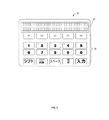
「ドライバー情報ディスプレイ」とも呼ばれる制御パネル30は、制御装置26に連結される。図2に示すように、制御パネル30は、ドライバーに情報を表示するディスプレイ32と、車両Vを操作する1つ以上の制御部34とを備える。図示の例では、ディスプレイ32はマルチラインLEDであり、制御部34は複数の固定式の設定可能なキーとして構成される。制御パネル30は異なる方法で構成することができ、例えばタッチスクリーンインタフェースという形をとり得ることがわかるであろう。制御パネル30に加えて、車両Vは、制御装置26に動作可能に連結された1つ以上の個別車両制御部、例えばアクセルペダル(図示せず)も備える。
A
任意で、制御装置26は、遠隔オペレータ又はディスパッチャによる双方向通信手段(図1参照、概略的に38で示す)を備えていてもよい。図示するように、制御装置26は、無線リンクを介してディスパッチャ38と通信するトランシーバ36に連結される。
Optionally, the
次に、本発明の一態様に従った駆動システム10の動作を更に詳細に説明する。「推進」モードと呼ばれる、トラクションモータトルクが車両を動かすために使用される通常の走行モードでは、制御装置26は、車両の重量の関数である1つ以上の出力目標を維持するように車両を作動させる。出力目標の一例は、例えば1トン当たりの電力出力として表される具体的な馬力荷重である。別の例では車両速度であり、それは車両の速度が、その質量、回転抵抗、及び付加された牽引力で決まるからである。
Next, the operation of
例として、既知のタイプの採掘トラックは、約175mt(メートルトン)(193トン)の空車重量を有し、定格が約2013kW(2700馬力)のディーゼル内燃機関エンジン12を備え、約218mt(240トン)の最大積載容量を有する。オペレータがアクセルペダルを押し下げるか又はその他の方法で車両移動を命令すると、制御装置26はエンジン12の負荷を調整する。エンジン12と共に組み込まれた別個のエンジン制御装置(図示せず)は、エンジン12への燃料流を調整して制御された負荷時の回転数(RPM)を維持する。その結果、エンジンの出力は、最大有効電力未満である馬力荷重目標に等しくなる。一例として、目標は約5.1kW/mt(6.2馬力/トン)にすることができる。これは、積載量が容量の約90%である場合、約1892kW(2536馬力)、即ち最大出力の約94%が必要ということになる。或いは、目標速度を使用することもでき、選択された目標速度は、実質的に特定の基準勾配及び積載量に対する最大エンジン出力で達成可能な最高速度未満である。
As an example, a known type of mining truck has an empty vehicle weight of about 175 mt (193 tons), a diesel
出力目標は、車両性能が広範囲にわたって実質的に等しくなるように所望量によって「均一に定められる(flat−rated)」。この例では、約5.1kW/mt(6.2馬力/トン)の目標馬力荷重は、最大積載容量における荷重に等しいため、必要に応じて、車両Vの全積載量範囲にわたって維持できるが、出力目標はトレードオフである。より高いエンジン出力を表す出力目標(速度又は動力荷重)は十分な加速と速度をもたらすのに対して、より低い出力目標は良好な整合性をもたらすと共に、所望の性能をより広い積載状況にわたって維持することも可能にする。 The output target is “flat-rated” by the desired amount so that the vehicle performance is substantially equal over a wide range. In this example, the target horsepower load of about 5.1 kW / mt (6.2 horsepower / ton) is equal to the load at the maximum load capacity and can be maintained over the entire load range of the vehicle V as required. The output target is a trade-off. A power target (speed or power load) that represents a higher engine power provides sufficient acceleration and speed, whereas a lower power target provides good consistency and maintains the desired performance over a wider load range It is also possible to do.
制御に用いられる特定のプロセスは決定的ではなく、車両速度の直接フィードバック制御によって、或いは電力出力の代用としてエンジンRPMを使用することによって、或いはインバータユニット20からの信号又はDCバス18からの電圧及び電流測定値を用いた実トルク及び/又は実馬力の計算によって実行してもよい。電力出力用のドライバーコマンドが出力目標未満(例えば、逆走又は低速走行中)であると、供給される電力は命令されたものと等しくなることになる。出力目標は、制御装置26において様々な方法でプログラムできる。例えば、出力目標をドライバーが手動で制御パネル30に入力してもよい。或いは、出力目標をディスパッチャ38によって車両Vに伝達してもよい。
The particular process used for control is not critical, either by direct feedback control of vehicle speed or by using engine RPM as a substitute for power output, or by signals from
荷重条件の変動に加えて、出力目標は車両性能の変動への適応にも役立つ。例えば、新品であっても、エンジンは一般的に±2%の性能変動を示す。車両10は使用して古くなるにつれて、車両ごとに性能にかなりの違いがある。出力目標を使用して、複数の車両10を集団内の最も劣った車両Vの性能に制限する。例えば、一連の車両10が移動しようとしており、各々の車両の総重量及び最大出力がわかっている場合、ディスパッチャ38は出力目標を計算して各々の車両Vに割り当てることができ、この場合、出力目標を各々の車両から実質的に等しい速度が得られるように計算することによって、車両の集団の数珠つなぎを防止できる。出力目標はその後、各々の車両Vに伝達されることになる。
In addition to changing load conditions, the output target is also useful for adapting to changes in vehicle performance. For example, even if it is new, the engine generally exhibits a performance variation of ± 2%. As the
駆動システム10は、最大トルク出力に関する限界値を組み込んでいる。従来技術と一貫して、これはトラクションモータ22への電流の流れを制限することによって行なわれる。通常、最大出力は、減速ギヤ等の構成部品の破損に対して許容可能なオーバーホール寿命及びマージンを提供するように設定される。時には、例えば車両Vが過重量又は柔らかい地形のために動かなくなるであろう場合など、これらの限界値を超えることが望ましい。低速、例えば上記の車両で約5.1km/時(3.2mph(マイル毎時))未満では、エンジン12から追加の出力を入手できる。従って、制御装置26を使用して、必要に応じて車両に一時的なトルクブーストを提供できる。そのようなブーストが必要な場合、制御装置26は、インバータ20にその出力を上昇させるように命令することによって、車輪23に一時的に余分なトルクを供給するように駆動システム10に命令する。
The
トルクブーストは、ドライバーによって、例えば制御パネル30に1つ以上のコマンドを入力することによって起動させる。無許可の要求を防止するために、コード又はその他のセキュリティ対策を使用してもよい。或いは、ブーストが必要な場合、トルクブーストを実施するためのコマンドをディスパッチャ38から制御装置26に伝達してもよい。
Torque boost is activated by the driver, for example, by inputting one or more commands to the
ブーストの使用は、駆動システム寿命に悪影響を及ぼさないことを確実にする様々な方法で制限できる。例えば、ブーストは、ブーストの適用時間、適用と適用の間の最短時間、最大トルクの増加量、或いは1日ごと、運転時間ごと、又はオーバーホールサイクルごとの適用総数によって制限してもよい。更に、特定の時間又は地理的地域での使用、或いは車両の積載量が所定の限界値を超えた場合に制限してもよい。制御装置26は、トルクブーストを使用した時、長さ、及び/又は程度のデータ記録を保存する。この情報を用いて、車両の使用料又は維持費を利用度に基づいて調整する。
The use of the boost can be limited in various ways to ensure that it does not adversely affect the drive system life. For example, the boost may be limited by the application time of the boost, the shortest time between applications, the amount of maximum torque increase, or the total number of applications per day, every driving time, or every overhaul cycle. Further, it may be limited to use at a specific time or geographical area, or when the loading capacity of the vehicle exceeds a predetermined limit value. The
グリッド抵抗器24及び関連するハードウェア(「減速(遅延)システム」とも呼ばれる)は、kW又はBTU(英国熱量単位)/時で表される所定の連続熱遮断限界値を有する。特定の勾配及び積載量に対してこれらの限界値が与えられると、車両Vが駆動され、且つ発電制動(本明細書では同じ意味で「減速(遅延)効果」と呼ばれる)のみを使用して車両速度の制御をなお維持できる最高速度が存在する。全ての勾配と積載量の組み合わせに対する最高速度を図にすると、それが駆動システムの減速領域を表すことになる。車両の摩擦ブレーキシステムの摩耗が増加することなく、より高い平均車両速度(及び短い移動時間)が可能になるので、できるだけこの領域の限界値付近で車両Vを作動させることが望ましい。高い信頼性を持って減速領域の限界値付近での動作を円滑にするために、制御装置26を使用して、車両Vに減速効果の一時的なブーストを必要に応じてもたらすことができる。
この機能を果たすために、減速運転中、制御装置26は、適用される実際の減速効果を測定し、これを減速領域と比較する。この比較は、例えば、車両の加速度を調べて減速領域内の車両速度をプロットするソフトウェアアルゴリズムを使用することによって達成できる。減速領域を超えた場合、例えば最大連続減速効果が適用されたが車両速度が増加し続けた場合、制御装置26は、車両Vを更に減速するために、連続限界値を超えて適用される減速効果を増大させる。増大した減速効果は、所定のマージンによって、車両Vが正常な減速領域に戻るまで保たれる。マージンの大きさは、最終的な車両速度が、低いレベルの減速効果でも車両の速度を維持しながら、それと同時に減速システムの熱回収を可能にするのに十分なほど低くなるように選択される。
To perform this function, during deceleration operation, the
上記のトルクブーストのように、更なる減速の使用は、駆動システム寿命に悪影響を及ぼさないことを確実にする様々な方法で制限できる。例えば、ブーストは、ブーストの適用時間、又は適用と適用の間の最短時間によって制限する。制御装置26は、更なる減速効果を適用した時、長さ、及び/又は程度の記録を保存する。この情報を用いて、車両の使用料又は維持費契約調整を利用度に基づいて調整する。
Like the torque boost described above, the use of further deceleration can be limited in various ways to ensure that it does not adversely affect drive system life. For example, the boost is limited by the application time of the boost or the shortest time between applications. The
本明細書に記載の制御システム及び方法は、従来技術の車両駆動システムに勝る数多くの利点を有する。推進運転中、車両Vは各々の積み荷に適合した重量比出力を有することになる。これにより、車両ごと且つ積み荷ごとの性能変動を減少させることによって、最も遅い車両の後ろに車両が集まる傾向が減少することになる。このため、ドライバーが前方の車両に追従してスロットルを断続的に作動させて速度を調整しようと試みた結果、燃料を無駄にしていたのとは対照的に、エンジン/駆動システムの組み合わせが最も効果的なポイントで作動することが可能になる。全エンジン出力が必要でない場合、駆動システムは、それでも必要な出力を供給できるようにエンジン速度を低下させることができる。更に、エンジン構成部品の応力/温度逸脱も減少する。必要な時にトルク出力を一時的にブーストすることにより、車両に牽引力を与えて必要に応じて引き離すが、適用を制限することによって構成部品寿命の低下を制限できる。最終的には、必要な時に減速効果を一時的にブーストすることにより、オペレータは、制御できなくなることはないという確信を持って減速領域の端により近い高速で運転できる。これは、車両の移動サイクル時間の向上につながる。 The control system and method described herein has a number of advantages over prior art vehicle drive systems. During propulsion operation, the vehicle V will have a weight ratio output adapted to each load. This reduces the tendency of the vehicle to collect behind the slowest vehicle by reducing performance fluctuations for each vehicle and for each load. For this reason, the engine / drive system combination is the best as opposed to wasting fuel as a result of the driver trying to adjust the speed by intermittently operating the throttle following the vehicle ahead. It becomes possible to operate at an effective point. If the full engine power is not needed, the drive system can still reduce the engine speed so that it can provide the required power. In addition, engine component stress / temperature excursions are reduced. By temporarily boosting the torque output when necessary, a traction force is applied to the vehicle and pulled away as necessary. However, by limiting the application, it is possible to limit the decrease in component life. Ultimately, by temporarily boosting the deceleration effect when needed, the operator can drive at higher speeds closer to the end of the deceleration region with confidence that it will not be out of control. This leads to an improvement in the movement cycle time of the vehicle.
以上、車両性能制御の方法を説明してきた。本発明の特定の実施形態を説明してきたが、当業者には、本発明の精神及び範囲から逸脱することなくこれらの実施形態に様々な変更を加えられることが明らかであろう。従って、前述の発明の好適な実施形態及び発明を実施するための最良の形態の説明は、例示のみを目的とするものであって、特許請求の範囲によって定義される本発明を限定することを意図したものではない。 The method for controlling vehicle performance has been described above. While particular embodiments of the present invention have been described, it will be apparent to those skilled in the art that various modifications can be made to these embodiments without departing from the spirit and scope of the invention. Accordingly, the foregoing description of preferred embodiments of the invention and the best mode for carrying out the invention are for illustrative purposes only and are intended to limit the invention as defined by the claims. Not intended.
Claims (15)
前記車両に載せられた電子制御装置を用いて、
少なくとも1つの牽引要素に接続された原動機を備える前記車両の駆動系からのパワー出力に対するドライバーコマンドを受け取り、
前記ドライバーコマンドに応じて、前記原動機によって前記車両を推進するように前記少なくとも1つの牽引要素にパワーを与える
ステップと、
を含み、
前記車両の前記少なくとも1つの牽引要素に供給されるパワー総量は、前記車両総重量に比例し、かつ前記電子制御装置により、前記ドライバーコマンドの大きさにかかわらず、前記車両総重量の単位重量当たりのパワーの所定比率を満たすように制限され、
前記所定比率は、前記原動機から得られる最大パワーを、前記積荷の重量を除く前記車両の重量で割った比よりも実質的に小さく、
前記車両は、異なる車両性能を有し、かつ、ともに移動する一連の複数の車両を含み、
前記車両総重量の単位重量当たりのパワーの所定比率は、少なくとも1つの電子制御装置を用いて、各車両の総重量と最大出力に基づいて、各車両から等しい速度が得られるように決定され、前記一連の複数の車両によって供給される前記パワー総量を制限するために用いられる、
方法。 Measuring the total weight of the vehicle including a weight of the vehicle and a weight of a load placed on the vehicle;
Using an electronic control device mounted on the vehicle,
Receiving a driver command for the power output from the driveline of the vehicle comprising a prime mover connected to at least one traction element;
Powering the at least one traction element to propel the vehicle by the prime mover in response to the driver command;
Including
The total amount of power supplied to the at least one traction element of the vehicle is proportional to the total vehicle weight and per unit weight of the total vehicle weight by the electronic controller regardless of the magnitude of the driver command. Limited to meet a predetermined ratio of power,
The predetermined ratio is substantially smaller than a ratio obtained by dividing the maximum power obtained from the prime mover by the weight of the vehicle excluding the weight of the load,
The vehicle includes a series of vehicles having different vehicle performance and moving together,
A predetermined ratio of power per unit weight of the gross vehicle weight, using one of the electronic control unit even without low, determined based on the total weight and the maximum output of each vehicle, so that the speed is equal from each vehicle to obtain And used to limit the total amount of power supplied by the series of vehicles.
Method.
少なくとも1つのトラクションモータが前記電源に電気的に連結され、
前記トラクションモータが前記少なくとも1つの牽引要素に連結される、
請求項1に記載の方法。 The prime mover is coupled to drive a power source;
At least one traction motor is electrically coupled to the power source;
The traction motor is coupled to the at least one traction element;
The method of claim 1.
車両の重量と、前記車両に載せられた積荷の重量とを含む前記車両総重量を測定し、
パワー出力に対するドライバーコマンドを受け取り、前記ドライバーコマンドに応じて、前記原動機によって前記車両を推進するように前記少なくとも1つの牽引要素にパワーを与える
ように構成された電子制御装置を備え、
前記車両の前記少なくとも1つの牽引要素に供給されるパワー総量は、前記車両総重量に比例し、かつ前記ドライバーコマンドの大きさにかかわらず、前記車両総重量の単位重量当たりのパワーの所定比率を満たすように制限され、
前記所定比率は、前記原動機から得られる最大パワーを、前記積荷の重量を除く前記車両の重量で割った比よりも実質的に小さく、
前記車両は、異なる車両性能を有し、かつ、ともに移動する一連の複数の車両を含み、
前記電子制御装置は、各車両の総重量と最大出力に基づいて、各車両から等しい速度が得られるように、前記車両総重量の単位重量当たりのパワーの所定比率を決定し、前記一連の複数の車両によって供給される前記パワー総量を制限するために用いられるように構成される、
システム。 An electronic controller connected to at least one electric traction motor of the vehicle, coupled to a prime mover connected to a power source and at least one traction element;
Measuring the total weight of the vehicle including a weight of the vehicle and a weight of a load placed on the vehicle;
An electronic controller configured to receive a driver command for power output and to power the at least one traction element to propel the vehicle by the prime mover in response to the driver command;
The total amount of power supplied to the at least one traction element of the vehicle is proportional to the total vehicle weight, and a predetermined ratio of the power per unit weight of the total vehicle weight regardless of the size of the driver command. Limited to meet ,
The predetermined ratio is substantially smaller than a ratio obtained by dividing the maximum power obtained from the prime mover by the weight of the vehicle excluding the weight of the load,
The vehicle includes a series of vehicles having different vehicle performance and moving together,
The electronic control unit determines a predetermined ratio of power per unit weight of the total vehicle weight so that an equal speed can be obtained from each vehicle based on the total weight and maximum output of each vehicle, and Configured to be used to limit the total amount of power supplied by the vehicle,
system.
前記制御装置は、
前記少なくとも1つのトラクションモータに所定の基準減速力を前記牽引要素に付加し、
減速領域を参照して前記車両の速度を測定し、
前記減速領域の境界を越えた前記車両速度に応じて、大きな減速力を前記牽引要素に付加し、
前記車両の速度が前記減速領域の前記境界に戻った場合、前記減速力を前記所定の基準減速力まで低下させる、
ようにさらにプログラムされる、
請求項10から14のいずれかに記載のシステム。
The at least one traction motor is coupled to an electrical energy absorber;
The controller is
A predetermined reference deceleration force is applied to the traction element on the at least one traction motor;
Measure the speed of the vehicle with reference to the deceleration area,
In accordance with the vehicle speed exceeding the boundary of the deceleration region, a large deceleration force is added to the traction element,
When the speed of the vehicle returns to the boundary of the deceleration region, the deceleration force is reduced to the predetermined reference deceleration force;
As further programmed,
15. A system according to any one of claims 10 to 14.
Applications Claiming Priority (3)
| Application Number | Priority Date | Filing Date | Title |
|---|---|---|---|
| US12/503,466 | 2009-07-15 | ||
| US12/503,466 US8774994B2 (en) | 2009-07-15 | 2009-07-15 | System and method for vehicle performance control |
| PCT/US2010/038775 WO2011008398A1 (en) | 2009-07-15 | 2010-06-16 | System and method for vehicle performance control |
Publications (2)
| Publication Number | Publication Date |
|---|---|
| JP2012533465A JP2012533465A (en) | 2012-12-27 |
| JP5841530B2 true JP5841530B2 (en) | 2016-01-13 |
Family
ID=43216322
Family Applications (1)
| Application Number | Title | Priority Date | Filing Date |
|---|---|---|---|
| JP2012520648A Active JP5841530B2 (en) | 2009-07-15 | 2010-06-16 | Vehicle performance control system and method |
Country Status (10)
| Country | Link |
|---|---|
| US (2) | US8774994B2 (en) |
| EP (1) | EP2454136A1 (en) |
| JP (1) | JP5841530B2 (en) |
| CN (1) | CN102548823B (en) |
| AU (1) | AU2010273900B2 (en) |
| BR (1) | BR112012001006A2 (en) |
| CL (1) | CL2012000129A1 (en) |
| IN (1) | IN2012DN00828A (en) |
| WO (1) | WO2011008398A1 (en) |
| ZA (1) | ZA201200768B (en) |
Families Citing this family (12)
| Publication number | Priority date | Publication date | Assignee | Title |
|---|---|---|---|---|
| US8972055B1 (en) * | 2011-08-19 | 2015-03-03 | Google Inc. | Methods and systems for selecting a velocity profile for controlling a robotic device |
| US8981685B2 (en) | 2011-12-23 | 2015-03-17 | Caterpillar Inc. | Controlling retarding torque in an electric drive system |
| JP2014027822A (en) * | 2012-07-30 | 2014-02-06 | Mitsubishi Motors Corp | Vehicle driving force control unit |
| SE538916C2 (en) * | 2014-01-15 | 2017-02-14 | Scania Cv Ab | Procedure and system for adjusting the performance of a vehicle |
| JP6504832B2 (en) * | 2014-01-28 | 2019-04-24 | ゼネラル・エレクトリック・カンパニイ | Integrated mounting and cooling devices, electronic devices and vehicles |
| JP6309355B2 (en) * | 2014-06-10 | 2018-04-11 | 日立建機株式会社 | Hybrid dump truck for mine |
| US10081349B2 (en) * | 2014-10-22 | 2018-09-25 | General Electric Company | System and method for engine control |
| ITUB20155877A1 (en) * | 2015-11-25 | 2017-05-25 | Tesmec Spa | COMMAND METHOD OF AN CONVENTION OF OPERATING VEHICLES FOR RAILWAY MAINTENANCE |
| CN109305049B (en) * | 2017-07-27 | 2021-09-03 | 郑州宇通客车股份有限公司 | Vehicle starting control method and device |
| DE102019105927B4 (en) * | 2019-03-08 | 2023-05-11 | Knorr-Bremse Systeme für Nutzfahrzeuge GmbH | System and method for determining a load change in a commercial vehicle |
| KR20200130773A (en) * | 2019-05-03 | 2020-11-20 | 현대자동차주식회사 | Apparatus for controlling an autonomous driving of vehicle, system having the same and method thereof |
| US20230036276A1 (en) * | 2021-08-02 | 2023-02-02 | Transportation Ip Holdings, Llc | Electric drive system for an engine |
Family Cites Families (33)
| Publication number | Priority date | Publication date | Assignee | Title |
|---|---|---|---|---|
| US4495449A (en) * | 1983-12-02 | 1985-01-22 | General Electric Company | Electric propulsion system for traction vehicles with automatic retard speed regulation |
| US5070959A (en) * | 1989-11-20 | 1991-12-10 | General Electric Company | Work vehicle having an electric propulsion system with adapted overspeed limit for traction motors |
| US5448479A (en) * | 1994-09-01 | 1995-09-05 | Caterpillar Inc. | Remote control system and method for an autonomous vehicle |
| JP3633707B2 (en) | 1996-03-08 | 2005-03-30 | 日産ディーゼル工業株式会社 | Vehicle group running control device |
| JP3557952B2 (en) * | 1999-07-22 | 2004-08-25 | 株式会社日立製作所 | Train control system |
| US6167343A (en) | 1999-08-02 | 2000-12-26 | General Motors Corporation | Method of governing acceleration in a vehicle throttle control system |
| GB2358845B (en) * | 2000-02-04 | 2002-03-13 | Michael Hawkins | Vehicle hybrid drive system and operating method |
| JP2001277901A (en) * | 2000-03-31 | 2001-10-10 | Nissan Diesel Motor Co Ltd | Vehicular constant-speed traveling device |
| US6425370B1 (en) | 2000-08-15 | 2002-07-30 | International Truck And Engine Corp. | Diesel engine load governing using engine speed setpoint |
| JP2002161776A (en) * | 2000-09-18 | 2002-06-07 | Fuji Heavy Ind Ltd | Working vehicle |
| JP4590132B2 (en) * | 2000-11-16 | 2010-12-01 | 本田技研工業株式会社 | Auto cruise equipment |
| US6601013B2 (en) * | 2000-12-20 | 2003-07-29 | Caterpillar Inc | Method and apparatus configured to determine the weight of a machine payload |
| US7137344B2 (en) * | 2001-03-27 | 2006-11-21 | General Electric Company | Hybrid energy off highway vehicle load control system and method |
| US6615118B2 (en) | 2001-03-27 | 2003-09-02 | General Electric Company | Hybrid energy power management system and method |
| US6721680B2 (en) * | 2001-12-21 | 2004-04-13 | Caterpillar Inc | Maximum payload speed manager |
| JP3536838B2 (en) | 2002-01-11 | 2004-06-14 | 日産自動車株式会社 | Vehicle driving force control device |
| JP2003211996A (en) * | 2002-01-18 | 2003-07-30 | Hitachi Ltd | Automatic speed controller for vehicle |
| JP3906717B2 (en) | 2002-03-19 | 2007-04-18 | トヨタ自動車株式会社 | Accelerator opening setting device and vehicle equipped with the same |
| US6842680B2 (en) | 2002-05-23 | 2005-01-11 | Caterpillar Inc | Method and apparatus for controlling ground speed of a work machine based on tire condition |
| JP3914857B2 (en) * | 2002-10-31 | 2007-05-16 | 日本車輌製造株式会社 | Large transport vehicle |
| US7034476B2 (en) | 2003-08-07 | 2006-04-25 | Siemens Energy & Automation, Inc. | System and method for providing automatic power control and torque boost |
| US7058502B2 (en) | 2003-11-20 | 2006-06-06 | International Engine Intellectual Property Company, Llc | Torque speed control authority for an engine having an all-speed governor |
| US7151992B2 (en) | 2003-12-17 | 2006-12-19 | Vrbia, Inc. | Externally activated non-negative acceleration system |
| JP4075863B2 (en) | 2004-06-07 | 2008-04-16 | 株式会社デンソー | Electric torque using vehicle |
| US7350611B2 (en) * | 2004-06-15 | 2008-04-01 | Caterpillar Inc | Method for controlling an electric drive machine |
| US7472008B2 (en) * | 2004-07-23 | 2008-12-30 | Caterpillar Inc. | Systems and methods for controlling mobile machine power |
| JP4400389B2 (en) | 2004-09-21 | 2010-01-20 | 株式会社デンソー | Drive motor control device |
| US7242311B2 (en) * | 2004-10-29 | 2007-07-10 | Caterpillar Inc. | Method and system for providing work machine multi-functional user interface |
| US7285926B2 (en) | 2005-06-30 | 2007-10-23 | General Electric Company | System and method for locomotive adhesion control |
| CN201052778Y (en) * | 2007-01-16 | 2008-04-30 | 朱久红 | Automobile accelerator pedal retarding mechanism |
| US7873452B2 (en) * | 2007-08-03 | 2011-01-18 | Detroit Diesel Corporation | Method and system for controlling a vehicle powertrain based upon actual vehicle load |
| US8103438B2 (en) * | 2007-09-26 | 2012-01-24 | Trimble Navigation Limited | Method and system for automatically directing traffic on a site |
| US8285456B2 (en) * | 2008-02-29 | 2012-10-09 | Caterpillar Inc. | System for controlling a multimachine caravan |
-
2009
- 2009-07-15 US US12/503,466 patent/US8774994B2/en active Active
-
2010
- 2010-06-16 IN IN828DEN2012 patent/IN2012DN00828A/en unknown
- 2010-06-16 CN CN201080041921.2A patent/CN102548823B/en active Active
- 2010-06-16 WO PCT/US2010/038775 patent/WO2011008398A1/en active Application Filing
- 2010-06-16 AU AU2010273900A patent/AU2010273900B2/en active Active
- 2010-06-16 JP JP2012520648A patent/JP5841530B2/en active Active
- 2010-06-16 BR BR112012001006A patent/BR112012001006A2/en not_active IP Right Cessation
- 2010-06-16 EP EP10731858A patent/EP2454136A1/en not_active Withdrawn
-
2012
- 2012-01-16 CL CL2012000129A patent/CL2012000129A1/en unknown
- 2012-01-31 ZA ZA2012/00768A patent/ZA201200768B/en unknown
-
2014
- 2014-06-02 US US14/293,064 patent/US20140277889A1/en not_active Abandoned
Also Published As
| Publication number | Publication date |
|---|---|
| EP2454136A1 (en) | 2012-05-23 |
| US20110015807A1 (en) | 2011-01-20 |
| BR112012001006A2 (en) | 2016-11-22 |
| US8774994B2 (en) | 2014-07-08 |
| US20140277889A1 (en) | 2014-09-18 |
| CN102548823B (en) | 2015-05-06 |
| IN2012DN00828A (en) | 2015-06-26 |
| AU2010273900B2 (en) | 2016-07-07 |
| WO2011008398A1 (en) | 2011-01-20 |
| ZA201200768B (en) | 2012-10-31 |
| AU2010273900A1 (en) | 2012-02-23 |
| CN102548823A (en) | 2012-07-04 |
| JP2012533465A (en) | 2012-12-27 |
| CL2012000129A1 (en) | 2012-08-24 |
Similar Documents
| Publication | Publication Date | Title |
|---|---|---|
| JP5841530B2 (en) | Vehicle performance control system and method | |
| US7460941B2 (en) | Slope-limited retarding control for a propelled machine | |
| KR100942093B1 (en) | Brake control device for electric vehicle | |
| JP5836272B2 (en) | Method and system for controlling the drive direction of an electrically driven machine | |
| CN105683009A (en) | Braking force control system | |
| JP6450761B2 (en) | System and method for controlling a vehicle | |
| US9187079B2 (en) | Retarding system for an electric drive machine | |
| US20070029874A1 (en) | Method and system for brake distribution in a regenerative braking system | |
| US20200094811A1 (en) | System and method for engine control | |
| JP3909328B2 (en) | Control method of vehicle hybrid drive | |
| EP2623361A1 (en) | Brake control apparatus for vehicle, and brake control apparatus for multi-car train | |
| US20060069487A1 (en) | Slope-limited retarding control for a propelled machine | |
| CN108473139A (en) | Method and apparatus for the measurement that the braking system during determining vehicle operating uses | |
| US8981685B2 (en) | Controlling retarding torque in an electric drive system | |
| US20230211768A1 (en) | Method for controlling powertrain, and powertrain | |
| JP2020515755A (en) | System and method for engine control |
Legal Events
| Date | Code | Title | Description |
|---|---|---|---|
| A621 | Written request for application examination |
Free format text: JAPANESE INTERMEDIATE CODE: A621 Effective date: 20130612 |
|
| A131 | Notification of reasons for refusal |
Free format text: JAPANESE INTERMEDIATE CODE: A131 Effective date: 20140527 |
|
| A521 | Request for written amendment filed |
Free format text: JAPANESE INTERMEDIATE CODE: A523 Effective date: 20140821 |
|
| A131 | Notification of reasons for refusal |
Free format text: JAPANESE INTERMEDIATE CODE: A131 Effective date: 20150303 |
|
| A521 | Request for written amendment filed |
Free format text: JAPANESE INTERMEDIATE CODE: A523 Effective date: 20150528 |
|
| TRDD | Decision of grant or rejection written | ||
| A01 | Written decision to grant a patent or to grant a registration (utility model) |
Free format text: JAPANESE INTERMEDIATE CODE: A01 Effective date: 20151020 |
|
| A61 | First payment of annual fees (during grant procedure) |
Free format text: JAPANESE INTERMEDIATE CODE: A61 Effective date: 20151113 |
|
| R150 | Certificate of patent or registration of utility model |
Ref document number: 5841530 Country of ref document: JP Free format text: JAPANESE INTERMEDIATE CODE: R150 |
|
| R250 | Receipt of annual fees |
Free format text: JAPANESE INTERMEDIATE CODE: R250 |
|
| R250 | Receipt of annual fees |
Free format text: JAPANESE INTERMEDIATE CODE: R250 |
|
| R250 | Receipt of annual fees |
Free format text: JAPANESE INTERMEDIATE CODE: R250 |
|
| R250 | Receipt of annual fees |
Free format text: JAPANESE INTERMEDIATE CODE: R250 |
|
| R250 | Receipt of annual fees |
Free format text: JAPANESE INTERMEDIATE CODE: R250 |
|
| R250 | Receipt of annual fees |
Free format text: JAPANESE INTERMEDIATE CODE: R250 |