JP5840071B2 - Method for manufacturing laminated core of electric motor - Google Patents
Method for manufacturing laminated core of electric motor Download PDFInfo
- Publication number
- JP5840071B2 JP5840071B2 JP2012108130A JP2012108130A JP5840071B2 JP 5840071 B2 JP5840071 B2 JP 5840071B2 JP 2012108130 A JP2012108130 A JP 2012108130A JP 2012108130 A JP2012108130 A JP 2012108130A JP 5840071 B2 JP5840071 B2 JP 5840071B2
- Authority
- JP
- Japan
- Prior art keywords
- core
- stator
- layer
- rotor
- laminated
- Prior art date
- Legal status (The legal status is an assumption and is not a legal conclusion. Google has not performed a legal analysis and makes no representation as to the accuracy of the status listed.)
- Expired - Fee Related
Links
Images


Description
この発明は、電動機に用いられる積層鉄心の製造方法に関し、積層鉄心の冷却効率の向上を目的とするものである。 The present invention relates to a method for manufacturing a laminated core used in an electric motor, and aims to improve the cooling efficiency of the laminated core.
従来の比較的大型の電動機の積層鉄心、例えば、軸方向長さ300mm〜500mm、直径300mm〜500mmといった積層鉄心の場合、積層鉄心の発熱により巻線の絶縁が劣化する。また、発熱により電磁鋼板の磁気的な特性が劣化するという問題があるので積層鉄心の冷却は必須である。 In the case of a conventional laminated iron core of a relatively large electric motor, for example, a laminated iron core having an axial length of 300 mm to 500 mm and a diameter of 300 mm to 500 mm, the insulation of the winding deteriorates due to heat generation of the laminated iron core. Moreover, since there exists a problem that the magnetic characteristic of an electromagnetic steel plate deteriorates by heat_generation | fever, cooling of a laminated iron core is essential.
例えば、特許文献1には、固定子鉄心コアプレートの内周側を切り欠いた円環状の複数のコアプレート、外周側を切り欠いた円環状の複数のコアプレート、貫通する開口部を持つ円環状の複数のコアプレートの三種類のコアプレートを積層し、円筒状の積層鉄心に円筒軸方向に連通する冷却のための連通孔を形成した積層鉄心が示されている。
For example, in
また、例えば、特許文献2には、磁界巻線を装着する磁極胴部及び磁極胴部の先端の磁極頭部が二種類の幅を有する薄板を積層してなるもので、この二種類の幅の薄板を複数枚ずつ積層したものを交互に重ねることにより、通風路を形成し、冷却効果を高めているものが示されている。
Further, for example, in
上記特許文献1に記載の電動機に用いられる積層鉄心では、積層鉄心に隙間を設け、ロータおよびステータを冷却しているが、隙間が小さく十分な冷却を行えない。また、電磁鋼板の形状を数種類用意する必要があるため、様々な種類の金型を準備する必要があり、費用が膨大となるという問題があった。
In the laminated iron core used in the electric motor described in
また、上記特許文献2に記載の電動機に用いられる積層鉄心では、通風ダクトの役割を果たす通風路を形成しているが、積層鉄心の端部から冷却しているので、積層鉄心の内部まで十分な冷却を期待できないという問題がある。また、二種類の電磁鋼板を使用するため、金型の費用がかかるという問題がある。
Moreover, in the laminated iron core used for the electric motor described in
この発明に係る電動機の積層鉄心の製造方法は、上記のような問題点を解決するためになされたものであり、積層鋼板を1種類にすることで、製作費用を抑え、かつ、積層鉄心の十分な冷却ができるようにすることを目的とする。 The method for manufacturing a laminated core of an electric motor according to the present invention has been made to solve the above-described problems. By using one type of laminated steel sheet, the manufacturing cost can be reduced, and the laminated iron core The purpose is to allow sufficient cooling.
本発明に係る電動機の積層鉄心の製造方法は、円筒形の固定子鉄心と上記固定子鉄心の内周に配置された回転子鉄心とを有し、上記固定子鉄心は、ヨーク部から径方向内方に突出する固定子ティース部を有する固定子鉄心単体の複数枚を積層してなり、上記回転子鉄心は、上記固定子鉄心と対向して径方向外方に突出する回転子ティース部を有する回転子鉄心単体の複数枚を積層してなる電動機の積層鉄心の製造方法において、
凸部が、一層と上記一層の次の層において異なった位置に一の積層方向に突出するように形成され、
上記凸部は、上記固定子ティース部及び回転子ティース部のいずれか一方または双方のティース部に形成され、
上記凸部は、上記ティース部の隣り合う周方向端部を90°折り曲げることによって形成され、上記折り曲げられた周方向端部と反対側の周方向端部は折り曲げられておらず、
上記積層の一層の上記ティース部の折り曲げられた周方向端部と上記一層の次の層の上記ティース部の折り曲げられていない周方向端部とが重ね合わせられ、上記積層の一層の上記ティース部の折り曲げられていない周方向端部と上記一層の次の層の上記ティース部の折り曲げられた周方向端部とが重ね合わせられて積層されているものである。
A method for manufacturing a laminated core of an electric motor according to the present invention includes a cylindrical stator core and a rotor core disposed on the inner periphery of the stator core, and the stator core is radially arranged from a yoke portion. A plurality of stator cores having a stator tooth portion projecting inward are stacked, and the rotor core has a rotor tooth portion projecting radially outward facing the stator core. In the manufacturing method of the laminated core of the electric motor formed by laminating a plurality of rotor cores having a single core ,
The protrusion is formed so as to protrude in one stacking direction at a different position in one layer and the next layer of the one layer,
The convex portion is formed on either one or both of the stator teeth portion and the rotor teeth portion ,
The convex portion is formed by bending 90 ° of adjacent circumferential end portions of the teeth portion, and the circumferential end portion on the opposite side of the folded circumferential end portion is not bent,
The folded circumferential end portion of the tooth portion of the one layer of the laminated layer and the unfolded circumferential end portion of the tooth portion of the next layer of the one layer are overlapped, and the teeth portion of the one layer of the laminated layer is overlapped The circumferential end portion that is not folded and the circumferential end portion that is folded of the tooth portion of the layer next to the first layer are overlapped and laminated .
また、円筒形の固定子鉄心と上記固定子鉄心の内周に配置された回転子鉄心とを有し、上記固定子鉄心は、ヨーク部から径方向内方に突出する固定子ティース部を有する固定子鉄心単体の複数枚を積層してなり、上記回転子鉄心は、上記固定子鉄心と対向して径方向外方に突出する回転子ティース部を有する回転子鉄心単体の複数枚を積層してなる電動機の積層鉄心の製造方法において、The stator core includes a cylindrical stator core and a rotor core disposed on the inner periphery of the stator core, and the stator core includes a stator teeth portion protruding radially inward from the yoke portion. A plurality of stator cores are stacked, and the rotor core is formed by stacking a plurality of rotor cores having a rotor teeth portion that protrudes radially outward in opposition to the stator core. In the manufacturing method of the laminated core of the electric motor,
凸部が、一層と上記一層の次の層において異なった位置に一の積層方向に突出するように形成され、The protrusion is formed so as to protrude in one stacking direction at a different position in one layer and the next layer of the one layer,
上記凸部は、上記固定子ティース部及び回転子ティース部のいずれか一方または双方のティース部に形成され、The convex portion is formed on either one or both of the stator teeth portion and the rotor teeth portion,
上記ティース部は、先端が周方向に突出した周方向突出部を有し、The teeth portion has a circumferential protrusion with a tip protruding in the circumferential direction,
上記凸部は、一部の上記ティース部の上記周方向突出部を切除し、上記ティース部の周方向中心線を中心軸として90度ねじり曲げることによって形成され、他部の上記ティース部はねじり曲げされておらず、The convex portion is formed by cutting out the circumferential protruding portion of a part of the tooth portions and twisting and bending 90 degrees around the circumferential center line of the teeth portion as a central axis. Not bent,
上記積層の一層の上記ねじり曲げによって形成された凸部と上記一層の次の層の上記ねじり曲げされていない上記ティース部とが重ね合わせられ、上記積層の一層のねじり曲げされていない上記ティース部と上記一層の次の層の上記ねじり曲げによって形成された凸部とが重ね合わせられて積層されているものである。The convex portion formed by the torsional bending of the one layer of the laminate and the untwisted teeth portion of the next layer of the first layer are overlapped, and the untwisted teeth portion of the laminated layer And the convex part formed by the torsional bending of the layer next to the first layer are stacked and laminated.
また、円筒形の固定子鉄心と上記固定子鉄心の内周に配置された回転子鉄心とを有し、上記固定子鉄心は、ヨーク部から径方向内方に突出する固定子ティース部を有する固定子鉄心単体の複数枚を積層してなり、上記回転子鉄心は、上記固定子鉄心と対向して径方向外方に突出する回転子ティース部を有する回転子鉄心単体の複数枚を積層してなる電動機の積層鉄心の製造方法において、
複数の凸部が、一層と上記一層の次の層において所定の位置に一の積層方向に突出するように形成され、
上記凸部は、上記固定ティース部及び回転子ティース部のいずれか一方または双方の上記ティース部若しくは上記ヨーク部に、頂部から下部に向けて幅が広くなるダイを用いたプレスにより形成されているものである。
The stator core includes a cylindrical stator core and a rotor core disposed on the inner periphery of the stator core, and the stator core includes a stator teeth portion protruding radially inward from the yoke portion. A plurality of stator cores are stacked, and the rotor core is formed by stacking a plurality of rotor cores having a rotor teeth portion that protrudes radially outward in opposition to the stator core. In the manufacturing method of the laminated core of the electric motor ,
A plurality of convex portions are formed so as to protrude in one stacking direction at a predetermined position in one layer and the next layer after the one layer,
The convex portion is formed on one or both of the fixed tooth portion and the rotor tooth portion by pressing using a die that increases in width from the top portion toward the lower portion. Is.
本発明に係る電動機の積層鉄心の製造方法によれば、回転子鉄心単体及び固定子鉄心単体のいずれか一方または双方を成形して一の積層方向に突出する凸部を設けて積層することによって積層間に隙間を形成し、隙間を設けた鉄心単体の全面に冷却風を流すことができ、回転子鉄心及び固定子鉄心のいずれか一方または双方を効率よく冷却することができる。 According to the method for manufacturing a laminated core of an electric motor according to the present invention, by forming one or both of a rotor core and a stator core alone and providing a projecting portion protruding in one lamination direction, the layers are laminated. A gap is formed between the stacked layers, and the cooling air can be flown over the entire surface of the iron core having the gap, so that one or both of the rotor core and the stator core can be efficiently cooled.
実施の形態1.
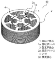
図1は、本発明に係る電動機の積層鉄心の実施の形態1を示す斜視図である。図1において、積層鉄心30は、円筒形の固定子鉄心2と固定子鉄心2の内周に配置された回転子鉄心1とを有し、固定子鉄心2は、円筒形ヨーク部内周から径方向内方に突出し、先端が周方向に突出した周方向突出部を有する電磁鋼板の複数枚を積層してなる固定子ティース2aを有し、回転子鉄心1は、固定子ティース2aと対向し、先端が周方向に突出した周方向突出部を有する電磁鋼板の複数枚を積層してなる回転子ティース1aを有する。また、固定子ティース2aには固定子巻線(図示せず)が施される。回転子ティース1aには回転子巻線(図示せず)が施され、回転子鉄心1の中心にはシャフト4が設けられている。回転子鉄心1とシャフト4は圧入により固定されている。
FIG. 1 is a perspective
図2は、本発明の実施の形態1における回転子鉄心単体の斜視図(a)及び断面図(b)である。図2に示したように、回転子鉄心単体6において、径方向に対向する一部の回転子ティース部7には回転子ティース部7の一部を一の積層方向に突出させて凸部8を形成し、他部の径方向に対向する回転子ティース部7には凸部8を形成していない。
FIG. 2 is a perspective view (a) and a sectional view (b) of the rotor core alone in the first embodiment of the present invention. As shown in FIG. 2, in the
図3は、本発明の実施の形態1における回転子鉄心の断面図(a)及び隙間部の拡大断面図(b)である。図3(a)に示したように、回転子鉄心1は、積層に際して、回転子鉄心単体6を回転して凸部8を形成していない他部の回転子ティース部7を凸部8を形成した一部の回転子ティース部7に重ね合わせて積層することで隙間9を形成することができる。
FIG. 3 is a cross-sectional view (a) of the rotor core and an enlarged cross-sectional view (b) of the gap portion in the first embodiment of the present invention. As shown in FIG. 3 (a), the
図3では、積層全体に凸部8を設けているが、本発明では、積層全体に凸部8を設ける必要はなく、積層の複数個所で凸部8を設ければよい。
In FIG. 3, the
本実施の形態1によれば、回転子ティース部7を成形することによって回転子鉄心単体6間に隙間9を設け、隙間9における回転子鉄心単体6の全面を冷却するように冷却風を流すことができるので、回転子鉄心1を効率よく冷却することができる。
According to the first embodiment, by forming the
また、回転子鉄心1は単一の回転子鉄心単体6で構成されるため、金型の種類を多く持つ必要はない。そのため、金型費用を抑えることができる。
Further, since the
なお、本実施の形態1では、回転子鉄心1の例を示したが、本実施の形態1は、図1に示した固定子鉄心2の固定子ティース2aを構成する固定子鉄心単体に同様の凸部を形成することによって、固定子鉄心2または回転子鉄心1と固定子鉄心2の双方にも同様に適用可能である。
In the first embodiment, the example of the
実施の形態2.
図4は、本発明に係る電動機の積層鉄心の実施の形態2を示す斜視図で、回転子鉄心単体を示した図である。図5は、本発明の実施の形態2における回転子鉄心の断面図(a)及び隙間部の拡大断面図(b)である。図4に示したように、回転子鉄心単体10における回転子ティース部7のうちの隣り合う一対の回転子ティース部7に、一対の回転子ティース部7の隣り合う周方向端部を90°折り曲げた凸部であるティース折り曲げ部11が形成され、ティース折り曲げ部11が形成された周方向端部と反対側の周方向端部にはティース折り曲げ部11が形成されていない。そして、積層の一層のティース折り曲げ部11と一層の次の層のティース折り曲げ部11を形成していない周方向端部とが重ね合わせて積層されていることによって、図5に示したように、隙間13を形成することができる。
FIG. 4 is a perspective view showing a second embodiment of the laminated core of the electric motor according to the present invention and is a diagram showing a single rotor core. FIG. 5: is sectional drawing (a) of the rotor core in
図5では、積層全体に凸部8を設けているが、本発明では、積層全体に凸部8を設ける必要はなく、積層の複数個所で凸部8を設ければよい。
In FIG. 5, the
本実施の形態2によれば、回転子ティース部7を成形することによって回転子鉄心単体10間に隙間9を設け、隙間9における回転子鉄心単体10の全面を冷却するように冷却風を流すことができるので、回転子鉄心1を効率よく冷却することができる。
According to the second embodiment, the
また、回転子鉄心単体10に折り曲げ部長さ12を大きくとることができ、回転子鉄心単体10を支える箇所が大きくなり、回転子鉄心1の大きな強度を確保することができる。
In addition, the
なお、本実施の形態2では、回転子鉄心1の例を示したが、本実施の形態2は、図1に示した固定子鉄心2の固定子ティース2aを構成する固定子鉄心単体に同様の折り曲げ部を形成することによって固定子鉄心2または回転子鉄心1と固定子鉄心2の双方にも適用可能である。
In the second embodiment, the example of the
実施の形態3.
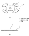
図6は、本発明に係る電動機の積層鉄心の実施の形態3を示す斜視図(a)及び隙間部の拡大断面図(b)である。図7は、本発明の実施の形態3における固定子鉄心の溶接部を示した図である。図6に示したように、固定子鉄心単体14の外周部の所定の箇所に、固定子鉄心単体14の所定の複数個所を成形して第一凸部である逆V型凸部16を設け、固定子鉄心単体14の固定子ティース部14aの先端を成形して所定の高さの第二凸部15を設けている。第二凸部15は、設けなくてもよい。そして、一層の逆V型凸部16の頂点16aに一層の次に積層する固定子鉄心単体14の逆V型凸部16の頂点16bを重ね合わせることによって、図6(b)に示したように、隙間17を形成することができる。
Embodiment 3 FIG.
FIG. 6: is the perspective view (a) which shows Embodiment 3 of the laminated iron core of the electric motor which concerns on this invention, and an expanded sectional view (b) of a clearance gap part. FIG. 7 is a diagram showing a welded portion of the stator core in the third embodiment of the present invention. As shown in FIG. 6, a plurality of predetermined portions of the
図6では、積層全体に逆V型凸部16を設けているが、本発明では、積層全体に逆V型凸部16を設ける必要はなく、積層の複数個所で逆V型凸部16を設ければよい。
In FIG. 6, the inverted V-shaped
本実施の形態3によれば、固定子鉄心単体14を成形することによって固定子鉄心単体14間に隙間17を設け、隙間17における固定子鉄心単体14の全面を冷却するように冷却風を流すことができるので、固定子鉄心2を効率よく冷却することができる。
According to the third embodiment, by forming the
また、従来より、固定子鉄心単体同士の固定は溶接により行われているが、図7に示したように、逆V型凸部16のV字頂点でそれぞれの固定子鉄心単体14が直線上に接触するようにし、この接触部を溶接部18とすることによって、固定子鉄心単体14同士を容易に固定することができる。
Conventionally, the stator cores are fixed to each other by welding. However, as shown in FIG. 7, each of the
なお、本実施の形態3では、逆V型凸部16の例を示したが、円弧形凸部、あるいは、台形凸部等の頂部の長さ(図6の16cに相当する長さ)が下部の長さより狭いダイを用いたプレスにより形成すればよい。また、この凸部は外周に限らず所定の箇所の複数個所に設ければよく、特に、3箇所以上に設けることによって、それぞれの固定子鉄心単体14を安定した状態で積層することができる。
In the third embodiment, an example of the inverted V-shaped
また、本実施の形態3では、固定子鉄心2の例を示したが、本実施の形態3は、回転子鉄心1または回転子鉄心1と固定子鉄心2の双方にも同様に適用可能である。この場合、逆V型凸部(第一凸部)16は、図1に示した回転子ティース1aに形成する。
In the third embodiment, the example of the
実施の形態4.
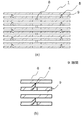
図8は、本発明に係る電動機の積層鉄心の実施の形態4を示す図であり、図8(a)は固定子鉄心単体の平面図、図8(b)は固定子鉄心の斜視図(b)である。図9は、本発明の実施の形態4における隙間部の拡大断面図(b)である。図8に示したよう、一部の固定子ティース部14aの先端部の周方向に突出した周方向突出部を切除し、固定子ティース部14aの周方向中心線を中心軸として90度ねじることにより凸部であるティース折り曲げ部20を形成する。そして、一層のティース折り曲げ部20と一層の次の層の折り曲げていない固定子ティース部14aとが重ね合わせて積層され、一層の折り曲げていない固定子ティース部14aと一層の次の層のティース折り曲げ部20とが重ね合わせて積層されることによって、図9に示したように、固定子鉄心2の固定子鉄心単体19間に隙間21を形成することができる。
Embodiment 4 FIG.
8A and 8B are diagrams showing a fourth embodiment of the laminated core of the electric motor according to the present invention. FIG. 8A is a plan view of the stator core alone, and FIG. 8B is a perspective view of the stator core. b). FIG. 9 is an enlarged cross-sectional view (b) of the gap portion according to the fourth embodiment of the present invention. As shown in FIG. 8, the circumferential projecting portion projecting in the circumferential direction of the distal end portion of a part of the
本実施の形態4によれば、固定子鉄心単体14を成形することによって固定子鉄心単体19間に隙間21を設け、隙間21における固定子鉄心単体14の全面を冷却するように冷却風を流すことができるので、固定子鉄心2を効率よく冷却することができる。
According to the fourth embodiment, by forming the
また、ティース折り曲げ部20で固定子鉄心単体19を支えるため、固定子鉄心2の大きな強度を確保できる。
Further, since the
なお、本実施の形態4では、固定子鉄心2の例を示したが、本実施の形態4は、図1に示した回転子鉄心1の回転子ティース1aを構成する回転子鉄心単体6に同様の折り曲げ部を形成することによって、回転子鉄心1または回転子鉄心1と固定子鉄心2の双方にも同様に適用可能である。
In the fourth embodiment, an example of the
実施の形態5.
図10は、本発明に係る電動機の積層鉄心の実施の形態5の固定子鉄心単体の平面図(a)及び固定子鉄心の積層状態を示す断面図(b)である。図10に示したように、固定子鉄心2のそれぞれの固定子鉄心単体22における固定子ティース部の周方向両端部を90度よりも小さい角度で折り曲げたティース折り曲げ部23を形成する。ティース折り曲げ部23を形成した部分の断面は台形となっているので、固定子鉄心単体22が重ね合わせて積層されることによって、図10(b)に示したように、隙間24が形成される。
Embodiment 5 FIG.
FIG. 10 is a plan view (a) of the stator core alone of the fifth embodiment of the laminated core of the electric motor according to the present invention and a sectional view (b) showing the laminated state of the stator core. As shown in FIG. 10,
本実施の形態5によれば、固定子鉄心単体22を成形することによって固定子鉄心単体22間に隙間24を設け、隙間24における固定子鉄心単体22の全面を冷却するように冷却風を流すことができるので、固定子鉄心2を効率よく冷却することができる。
According to the fifth embodiment, by forming the
なお、本実施の形態5では、固定子鉄心2の例を示したが、本実施の形態5は、図1に示した回転子鉄心1の回転子ティース1aを構成する回転子鉄心単体6に同様の折り曲げ部を形成することによって回転子鉄心1または回転子鉄心1と固定子鉄心2の双方にも適用可能である。
In the fifth embodiment, the example of the
また、回転子鉄心1が回転した場合、図10に示したように、固定子ティース部14aを径方向からずれた斜め方向に形成することにより、冷却風の流れがよくなり、流量の損失なく固定子鉄心2を冷却することができる。
Further, when the
なお、本発明は、その発明の範囲内において、各実施の形態を自由に組み合わせたり、各実施の形態を適宜、変形、省略することが可能である。 It should be noted that the present invention can be freely combined with each other within the scope of the invention, and each embodiment can be appropriately modified or omitted.
本発明に係る電動機の積層鉄心の製造方法は、電気掃除機等のモーター部に有効に利用することができる。 The method for manufacturing a laminated core of an electric motor according to the present invention can be effectively used for a motor part such as a vacuum cleaner.
1 回転子鉄心、1a 回転子ティース、2 固定子鉄心、2a 固定子ティース、
4 シャフト、6,10 回転子鉄心単体、7 回転子ティース部、8,15 凸部、
9,13,17、24 隙間、10 回転子鉄心単体、
11,20,23 ティース折り曲げ部、12 折り曲げ部長さ、
14,19,22 固定子鉄心単体、14a 固定子ティース部、16 逆V型凸部、
16a,16b 頂点、18 溶接部、30 積層鉄心。
1 Rotor core, 1a Rotor teeth, 2 Stator core, 2a Stator teeth,
4 shaft, 6, 10 rotor core alone, 7 rotor teeth, 8, 15 convex,
9, 13, 17, 24 clearance, 10 rotor core alone,
11, 20, 23 Teeth bent portion, 12 bent portion length,
14, 19, 22 Stator core alone, 14a Stator teeth portion, 16 Inverted V-shaped convex portion,
16a, 16b vertex, 18 welds, 30 laminated core.
Claims (5)
凸部が、一層と上記一層の次の層において異なった位置に一の積層方向に突出するように形成され、
上記凸部は、上記固定子ティース部及び回転子ティース部のいずれか一方または双方のティース部に形成され、
上記凸部は、上記ティース部の隣り合う周方向端部を90°折り曲げることによって形成され、上記折り曲げられた周方向端部と反対側の周方向端部は折り曲げられておらず、
上記積層の一層の上記ティース部の折り曲げられた周方向端部と上記一層の次の層の上記ティース部の折り曲げられていない周方向端部とが重ね合わせられ、上記積層の一層の上記ティース部の折り曲げられていない周方向端部と上記一層の次の層の上記ティース部の折り曲げられた周方向端部とが重ね合わせられて積層されていることを特徴とする電動機の積層鉄心の製造方法。 A stator having a cylindrical stator core and a rotor core disposed on the inner periphery of the stator core, and the stator core has a stator tooth portion protruding radially inward from the yoke portion. A plurality of single cores are stacked, and the rotor core is formed by stacking a plurality of single cores having a rotor teeth portion that protrudes radially outward to face the stator core. In the manufacturing method of the laminated core of the electric motor,
The protrusion is formed so as to protrude in one stacking direction at a different position in one layer and the next layer of the one layer,
The convex portion is formed on either one or both of the stator teeth portion and the rotor teeth portion,
The convex portion is formed by bending 90 ° of adjacent circumferential end portions of the teeth portion, and the circumferential end portion on the opposite side of the folded circumferential end portion is not bent,
The folded circumferential end portion of the tooth portion of the one layer of the laminated layer and the unfolded circumferential end portion of the tooth portion of the next layer of the one layer are overlapped, and the teeth portion of the one layer of the laminated layer is overlapped A method of manufacturing a laminated core of an electric motor, wherein the unfolded circumferential end portion and the folded circumferential end portion of the teeth portion of the next layer are stacked and laminated .
凸部が、一層と上記一層の次の層において異なった位置に一の積層方向に突出するように形成され、
上記凸部は、上記固定子ティース部及び回転子ティース部のいずれか一方または双方のティース部に形成され、
上記ティース部は、先端が周方向に突出した周方向突出部を有し、
上記凸部は、一部の上記ティース部の上記周方向突出部を切除し、上記ティース部の周方向中心線を中心軸として90度ねじり曲げることによって形成され、他部の上記ティース部はねじり曲げされておらず、
上記積層の一層の上記ねじり曲げによって形成された凸部と上記一層の次の層の上記ねじり曲げされていない上記ティース部とが重ね合わせられ、上記積層の一層のねじり曲げされていない上記ティース部と上記一層の次の層の上記ねじり曲げによって形成された凸部とが重ね合わせられて積層されていることを特徴とする電動機の積層鉄心の製造方法。 A stator having a cylindrical stator core and a rotor core disposed on the inner periphery of the stator core, and the stator core has a stator tooth portion protruding radially inward from the yoke portion. A plurality of single cores are stacked, and the rotor core is formed by stacking a plurality of single cores having a rotor teeth portion that protrudes radially outward to face the stator core. In the manufacturing method of the laminated core of the electric motor,
The protrusion is formed so as to protrude in one stacking direction at a different position in one layer and the next layer of the one layer,
The convex portion is formed on either one or both of the stator teeth portion and the rotor teeth portion,
The teeth portion has a circumferential protrusion with a tip protruding in the circumferential direction,
The convex portion is formed by cutting out the circumferential protruding portion of a part of the tooth portions and twisting and bending 90 degrees around the circumferential center line of the teeth portion as a central axis. Not bent,
The convex portion formed by the torsional bending of the one layer of the laminate and the untwisted teeth portion of the next layer of the first layer are overlapped, and the untwisted teeth portion of the laminated layer and the further method for manufacturing a laminated core of an electric motor, wherein a and the torsion bent projections formed by the next layer are laminated superposed.
複数の凸部が、一層と上記一層の次の層において所定の位置に一の積層方向に突出するように形成され、
上記凸部は、上記固定子ティース部及び回転子ティース部のいずれか一方または双方のティース部若しくは上記ヨーク部に、頂部から下部に向けて幅が広くなるダイを用いたプレスにより形成されていることを特徴とする電動機の積層鉄心の製造方法。 A stator having a cylindrical stator core and a rotor core disposed on the inner periphery of the stator core, and the stator core has a stator tooth portion protruding radially inward from the yoke portion. A plurality of single cores are stacked, and the rotor core is formed by stacking a plurality of single cores having a rotor teeth portion that protrudes radially outward to face the stator core. In the manufacturing method of the laminated core of the electric motor ,
A plurality of convex portions are formed so as to protrude in one stacking direction at a predetermined position in one layer and the next layer after the one layer,
The convex portion is formed on one or both of the stator teeth portion and the rotor teeth portion or the yoke portion by pressing using a die whose width increases from the top portion toward the lower portion. A method for manufacturing a laminated iron core of an electric motor .
Priority Applications (1)
| Application Number | Priority Date | Filing Date | Title |
|---|---|---|---|
| JP2012108130A JP5840071B2 (en) | 2012-05-10 | 2012-05-10 | Method for manufacturing laminated core of electric motor |
Applications Claiming Priority (1)
| Application Number | Priority Date | Filing Date | Title |
|---|---|---|---|
| JP2012108130A JP5840071B2 (en) | 2012-05-10 | 2012-05-10 | Method for manufacturing laminated core of electric motor |
Publications (3)
| Publication Number | Publication Date |
|---|---|
| JP2013236499A JP2013236499A (en) | 2013-11-21 |
| JP2013236499A5 JP2013236499A5 (en) | 2014-11-20 |
| JP5840071B2 true JP5840071B2 (en) | 2016-01-06 |
Family
ID=49762165
Family Applications (1)
| Application Number | Title | Priority Date | Filing Date |
|---|---|---|---|
| JP2012108130A Expired - Fee Related JP5840071B2 (en) | 2012-05-10 | 2012-05-10 | Method for manufacturing laminated core of electric motor |
Country Status (1)
| Country | Link |
|---|---|
| JP (1) | JP5840071B2 (en) |
Families Citing this family (5)
| Publication number | Priority date | Publication date | Assignee | Title |
|---|---|---|---|---|
| CN109075626B (en) * | 2016-05-09 | 2021-01-15 | 三菱电机株式会社 | Stator core and motor provided with same |
| JP7151602B2 (en) * | 2019-04-12 | 2022-10-12 | トヨタ紡織株式会社 | Rotating electric machine |
| JP6687272B1 (en) * | 2019-05-10 | 2020-04-22 | 株式会社一宮電機 | Rotating electric machine and method for manufacturing core |
| JP7302488B2 (en) * | 2020-01-16 | 2023-07-04 | トヨタ自動車株式会社 | laminated core |
| DE102020133287B3 (en) * | 2020-12-14 | 2022-01-27 | Voith Patent Gmbh | Rotor rim for an electrical machine |
Family Cites Families (6)
| Publication number | Priority date | Publication date | Assignee | Title |
|---|---|---|---|---|
| JPS62107404U (en) * | 1985-12-25 | 1987-07-09 | ||
| JPH08126263A (en) * | 1994-10-28 | 1996-05-17 | Yaskawa Electric Corp | Laminated iron core of electric equipment, and its manufacture |
| JP3629071B2 (en) * | 1995-09-14 | 2005-03-16 | ティーアールダブリュ オートモーティブ ジャパン株式会社 | Electric motor stator and method of manufacturing electric motor stator |
| JP2009072014A (en) * | 2007-09-14 | 2009-04-02 | Yaskawa Electric Corp | Core block, core, stator for electric motor, and its electric motor |
| CN102640397A (en) * | 2009-12-24 | 2012-08-15 | 株式会社安川电机 | Core stack, motor provided with core stack, and method for manufacturing core stack |
| WO2011101986A1 (en) * | 2010-02-22 | 2011-08-25 | トヨタ自動車株式会社 | Stator and method for producing same |
-
2012
- 2012-05-10 JP JP2012108130A patent/JP5840071B2/en not_active Expired - Fee Related
Also Published As
| Publication number | Publication date |
|---|---|
| JP2013236499A (en) | 2013-11-21 |
Similar Documents
| Publication | Publication Date | Title |
|---|---|---|
| JP4907654B2 (en) | Split type iron core and manufacturing method thereof, stator iron core | |
| JP5840071B2 (en) | Method for manufacturing laminated core of electric motor | |
| JP2012023861A (en) | Armature core and motor | |
| JP5660058B2 (en) | Core block, stator, rotating electric machine, and manufacturing method of core block | |
| TW201218577A (en) | Rotating electrical machine, manufacturing method of rotating electrical machine, and wind power generator system | |
| JP6155429B2 (en) | Armature winding or field winding of generator by concentrated winding and manufacturing method thereof | |
| TWI443938B (en) | Stator unit, winding method therefor, stator structure using the same; and manufacture therefor | |
| JP5644880B2 (en) | Rotating electric machine | |
| JP2007244065A (en) | Stator structure of concentrated winding motor | |
| JP2007221927A (en) | Stator core of rotating electric machine and method of manufacturing same | |
| JP2011147200A (en) | Motor armature | |
| JP4568639B2 (en) | Stator | |
| JP2010017003A (en) | Stator core of rotating electric machine | |
| JP2016116421A (en) | Rotary electric machine | |
| JP4705947B2 (en) | Stator manufacturing method | |
| JP6117608B2 (en) | Rotating electrical machine laminated iron core | |
| JP5278238B2 (en) | Rotating electric machine | |
| JP2020184832A (en) | Coil, stator member, stator, and motor | |
| JP2011229312A (en) | Layered core | |
| JP2009095189A (en) | Split stator and motor | |
| JP2014045641A (en) | Stator core of dynamo-electric machine | |
| JP5528164B2 (en) | Stator for rotating electrical machine and method for manufacturing the same | |
| JP5292134B2 (en) | Stator and motor | |
| JP5726118B2 (en) | Laminated stator core, method for producing laminated stator core | |
| JP5977182B2 (en) | motor |
Legal Events
| Date | Code | Title | Description |
|---|---|---|---|
| A521 | Written amendment |
Free format text: JAPANESE INTERMEDIATE CODE: A523 Effective date: 20141003 |
|
| A621 | Written request for application examination |
Free format text: JAPANESE INTERMEDIATE CODE: A621 Effective date: 20141003 |
|
| A977 | Report on retrieval |
Free format text: JAPANESE INTERMEDIATE CODE: A971007 Effective date: 20150731 |
|
| A131 | Notification of reasons for refusal |
Free format text: JAPANESE INTERMEDIATE CODE: A131 Effective date: 20150804 |
|
| A521 | Written amendment |
Free format text: JAPANESE INTERMEDIATE CODE: A523 Effective date: 20150925 |
|
| TRDD | Decision of grant or rejection written | ||
| A01 | Written decision to grant a patent or to grant a registration (utility model) |
Free format text: JAPANESE INTERMEDIATE CODE: A01 Effective date: 20151013 |
|
| A61 | First payment of annual fees (during grant procedure) |
Free format text: JAPANESE INTERMEDIATE CODE: A61 Effective date: 20151110 |
|
| R150 | Certificate of patent or registration of utility model |
Ref document number: 5840071 Country of ref document: JP Free format text: JAPANESE INTERMEDIATE CODE: R150 |
|
| LAPS | Cancellation because of no payment of annual fees |