JP5839552B2 - Wireless metering meter position detection method - Google Patents
Wireless metering meter position detection method Download PDFInfo
- Publication number
- JP5839552B2 JP5839552B2 JP2011228902A JP2011228902A JP5839552B2 JP 5839552 B2 JP5839552 B2 JP 5839552B2 JP 2011228902 A JP2011228902 A JP 2011228902A JP 2011228902 A JP2011228902 A JP 2011228902A JP 5839552 B2 JP5839552 B2 JP 5839552B2
- Authority
- JP
- Japan
- Prior art keywords
- meter
- radio wave
- antenna
- wireless
- signal
- Prior art date
- Legal status (The legal status is an assumption and is not a legal conclusion. Google has not performed a legal analysis and makes no representation as to the accuracy of the status listed.)
- Active
Links
Images


Landscapes
- Mobile Radio Communication Systems (AREA)
Description
本発明は、無線検針システムを搭載したメータ類の位置を特定する技術に関し、詳しくは無線検針システムを搭載したメータ類の発信する信号を受信手段にて受信し、受信した信号を用いてメータ類の位置を特定する方法に関する。 The present invention relates to a technique for specifying the position of meters equipped with a wireless meter reading system, and more specifically, a signal transmitted from a meter equipped with a wireless meter reading system is received by a receiving means, and the meters using the received signal. The present invention relates to a method for specifying the position.
無線検針システムは、無線を用いてガスメータ等を検針する為に開発されたシステムである。従来、例えばガスメータの検針業務は、ガスメータが設置されている場所に検針員が赴き、目視でガスメータのカウンタを確認しなければならなかった。しかし、ガスメータに無線通信機能を有した子機を取り付ける事で、情報処理端末と連携する親機を用いてガスメータから離れた位置からでもガスメータの検針が可能となった。検針員は親機を操作するだけで検針が可能となるのである。これは、例えば建物室内に設置されたガスメータの検針の手間を省く点で効果があり、作業効率を向上させることができる。 The wireless meter reading system is a system developed to measure a gas meter or the like using wireless. Conventionally, for example, in a meter reading operation of a gas meter, a meter reader has to go to the place where the gas meter is installed and visually check the counter of the gas meter. However, by attaching a slave unit having a wireless communication function to the gas meter, the meter reading of the gas meter can be performed even from a position away from the gas meter using a master unit that cooperates with the information processing terminal. The meter reader can read the meter only by operating the master unit. This is effective, for example, in that it eliminates the trouble of meter reading of a gas meter installed in a building room, and can improve work efficiency.
例えば特許文献1には、無線検針システムに関する技術が開示されている。親機にGPS(Global Positioning System)を搭載し、GPSにより常に更新される親機の現在位置データと親機に予め登録されている各戸に設置された子機の位置データとから、親機の現在位置に応じた検針対象子機を順次選定する。そして選定された子機から送信される検針データを順次受信して自動的に検針することができる。こうして検針員の作業負担を大幅に軽減することが可能となっている。このように無線検針システムを利用した技術についても幾つか検討されている。 For example, Patent Document 1 discloses a technique related to a wireless meter reading system. GPS (Global Positioning System) is installed in the master unit, and the master unit's current location data that is constantly updated by GPS and the location data of the slave units installed in each unit registered in the master unit in advance Select the metering slaves according to the current position. And the meter-reading data transmitted from the selected subunit | mobile_unit can be received sequentially, and a meter-reading can be performed automatically. In this way, it is possible to greatly reduce the workload of the meter reader. Some techniques using the wireless meter reading system have been studied.
しかしながら、無線検針システムがこのような離れた位置からでもメータ類の検針ができる機能を有することで、新たな問題点が指摘される。特許文献1に示される方法などで無線検針メータを用い、運用した結果、検針すべきメータ類の本体の位置が確認しづらくなるという点である。検針すべきメータ類は、無線で検針が可能な故に、視認し辛い位置に配置されたり、検針メータの前に荷物の仮置き場が設置されたりする事情が許容される。その結果、各室の使用者の都合で検針メータの前に壁が設けられるようなケースもある。 However, a new problem is pointed out because the wireless meter reading system has a function of meter reading even from such a remote position. As a result of using and operating a wireless meter-reading meter in the method disclosed in Patent Document 1, it is difficult to confirm the position of the main body of meters to be metered. Since the meters to be metered can be metered wirelessly, it is allowed to be placed at a position where it is difficult to visually check or a temporary storage place for luggage is installed in front of the meter meter. As a result, there are cases where a wall is provided in front of the meter-reading meter for the convenience of the user in each room.
メータ類を検針するだけであれば、これらの事態は無線検針システムを用いる限り問題とならないが、例えばガスメータは定期的に交換しなければならない法定義務を負っている。これは定期的にガスメータを校正する等の必要があるためである。また、ガスメータに取り付けられる無線検針システムの子機も通信のために電池を必要とし、内蔵しているためこれを定期的に交換する必要もある。このため、ガスメータの交換時にはガスメータの取り付け位置を確認できる必要がある。他のメータ類に関しても似たような事情を抱えている。 If only meter reading is performed, these situations will not be a problem as long as a wireless meter reading system is used. However, for example, gas meters have legal definitions that must be replaced periodically. This is because it is necessary to periodically calibrate the gas meter. Moreover, since the subunit | mobile_unit of the wireless meter-reading system attached to a gas meter also needs a battery for communication, since it is built in, it is also necessary to replace | exchange this regularly. For this reason, it is necessary to be able to confirm the installation position of the gas meter when replacing the gas meter. There are similar circumstances for other meters.
しかしながら現場での運用は、検針員が無線検針システムを運用することでガスメータそのものを目視で確認する機会が低減する上、上述のようにガスメータの前に荷物が仮置きされたり壁が設置されたりしたとしても、検針員が検針することの妨げにはならないため、積極的にガスメータの位置を確認しなくなる。さらに、検針員が交代し引き継ぎする際に必要な情報が十分に伝達されない等の事情も、ガスメータの位置を特定しにくくする要因となっている。しかしながら、いざガスメータの交換作業をするにあたっては、短時間で交換作業を行いたいという事情がある。しかし、隠されたガスメータを探すことも交換作業員の作業範囲とすると、交換作業員の作業負担が増大し、作業効率が悪化してしまう。 However, on-site operation reduces the opportunity for the meter reader to visually check the gas meter itself by operating the wireless meter reading system, and as mentioned above, luggage is temporarily placed in front of the gas meter or walls are installed. Even if it does, it will not interfere with the meter reading, so it will not actively check the position of the gas meter. Furthermore, the situation that the information necessary when the meter reader changes and takes over is not sufficiently transmitted, which makes it difficult to specify the position of the gas meter. However, when replacing the gas meter, there is a situation where it is desired to perform the replacement work in a short time. However, if searching for a hidden gas meter is also within the work range of the replacement worker, the work load on the replacement worker increases and the work efficiency deteriorates.
従来通りの検針を行っていた場合は、目視での検針であったためにこのような課題は生じていなかったが、無線検針システムを導入し始め、無線検針システムを備えたガスメータの交換時期になって初めてこのような問題があることが判明した。そこで、出願人は特定小電力無線を用いて位置を特定することを考案した。無線検針システムは特定小電力無線の電波帯域を使用して無線通信を行っているためである。しかし、無線検針システムは省電力で長期間電池交換をしないことを前提としているため、親機の信号に対して数十秒の間隔を開けて短時間のアンサーバック信号を短時間発信する設定になっている。したがって、このアンサーバック信号を用い、既存技術で位置特定をすることは困難である。 When the conventional meter reading was performed, this problem was not caused because it was a visual meter reading. However, it was time to replace the gas meter equipped with the wireless metering system after the introduction of the wireless metering system began. It was discovered for the first time that there was such a problem. Therefore, the applicant has devised specifying a position using a specific low-power radio. This is because the wireless meter reading system performs wireless communication using a specific low power radio wave band. However, since the wireless meter reading system is based on the premise that the battery will not be replaced for a long time with power saving, it is set to send a short answer back signal for a short time with an interval of several tens of seconds with respect to the signal of the master unit. It has become. Therefore, it is difficult to specify the position using the existing technology using this answerback signal.
そこで、本発明はこのような課題を解決するために、現場の無線検針システムを使用したガスメータを探し出すことのできる無線検針メータ位置検出方法を提供することを目的とする。 Therefore, in order to solve such a problem, an object of the present invention is to provide a wireless metering meter position detection method capable of finding a gas meter using a wireless metering system in the field.
前記目的を達成するために、本発明の一態様による無線検針メータ位置検出方法は以下のような特徴を有する。 In order to achieve the above object, a wireless metering meter position detection method according to an aspect of the present invention has the following characteristics.
(1)無線を利用して検針データを通知する子機と、前記子機に通知信号を発信するように発信指令信号を送る親機と、前記子機から通知された前記通知信号を取得する為のアンテナと接続する受信手段と、前記受信手段から前記通知信号のデータを取得し、受信強度を記録する記憶手段と、前記受信強度を示す表示手段と、を備え、第1特定手順として、前記アンテナを備えた前記受信手段を複数並べ、前記親機から前記発信指令信号を出し、前記発信指令信号に応える前記通知信号を前記受信手段でそれぞれ受信し、前記表示手段でそれぞれの前記アンテナが受信した信号強度を表示し、前記子機の存在する方角を特定し、前記信号強度が最も高かった前記アンテナの位置を参考に、前記第1特定手順を繰り返すことで、前記子機の大体の位置を把握し、第2特定手順として、指向性を高める為の円筒体を備えた指向性アンテナを、前記受信手段に接続し、前記指向性アンテナを備えた前記受信手段を複数並べ、前記親機から前記発信指令信号を出し、前記発信指令信号に応える前記通知信号を、前記受信手段でそれぞれ受信し、前記表示手段でそれぞれの前記指向性アンテナが受信した信号強度を表示し、前記子機の存在する位置を特定し、前記第2特定手順で前記子機の存在する位置を特定できなかった場合に、前記信号強度が最も高かった前記指向性アンテナの位置を参考に、前記第2特定手順を繰り返すことで、前記子機の位置を把握すること、を特徴とするものである。 (1) A slave unit that notifies the meter reading data using radio, a master unit that sends a transmission command signal so as to transmit a notification signal to the slave unit, and the notification signal notified from the slave unit is acquired. Receiving means connected to an antenna for receiving, storage means for acquiring data of the notification signal from the receiving means and recording the received intensity, and a display means for indicating the received intensity, as a first specific procedure, A plurality of receiving means including the antenna are arranged, the transmission command signal is output from the master unit, the notification signal corresponding to the transmission command signal is received by the receiving means, and each antenna is received by the display means. display received signal strength to identify the direction that exists in the slave machine, referring to the position of the antenna the signal strength is the highest, by repeating the first specific procedure, approximate slave machine Position to grasp the, as a second specifying step, the directional antenna comprising a cylindrical body for enhancing the directivity, connected to said receiving means, arranging a plurality of said receiving means with the directional antenna, the parent The transmission command signal is output from the machine, the notification signal corresponding to the transmission command signal is received by the receiving means, the signal strength received by the directional antenna is displayed by the display means, and the slave unit is displayed. When the position where the slave is present cannot be specified in the second specifying procedure, the second specifying is performed with reference to the position of the directional antenna having the highest signal strength. It is characterized in that the position of the slave unit is grasped by repeating the procedure.
このような特徴を有する本発明の一態様による無線検針メータ位置検出方法により、以下のような作用、効果が得られる。 With the wireless metering meter position detection method according to one aspect of the present invention having such characteristics, the following operations and effects can be obtained.
上記(1)に記載される態様は、無線を利用して検針データを通知する子機と、子機に通知信号を発信するように発信指令信号を送る親機と、子機から通知された通知信号を取得する為のアンテナと接続する受信手段と、受信手段から通知信号のデータを取得し、受信強度を記録する記憶手段と、受信強度を示す表示手段を備えた、無線検針メータ位置検出方法であり、第1特定手順と第2特定手順を用いて目的のメータの位置を探し出すことが可能である。 The aspect described in the above (1) is notified from the slave unit that notifies the meter reading data using radio, the master unit that sends a transmission command signal so as to transmit a notification signal to the slave unit, and the slave unit Wireless meter reading position detecting means comprising a receiving means connected to an antenna for obtaining a notification signal, a storage means for obtaining data of the notification signal from the receiving means and recording the received intensity, and a display means for indicating the received intensity It is a method, and it is possible to find the position of the target meter using the first specific procedure and the second specific procedure.
第1特定手順として、アンテナを備えた受信手段を複数並べ、親機から発信指令信号を出し、発信指令信号に応える通知信号を受信手段でそれぞれ受信し、表示手段でそれぞれのアンテナが受信した信号強度を表示し、子機の存在する方角を特定する。例えば第1アンテナを備える受信手段、第2アンテナを備える受信手段、第3アンテナ備える受信手段が3つあった場合、これら受信手段を横に並べて測定することで、それぞれの受信手段が受信した電界強度を表示手段が表示する。その結果、3つのアンテナの内、最も信号検出強度が高いアンテナが子機の近くにあることが分かる。例えば第1アンテナが受信した信号検出強度が最も高ければ、他の2つよりも検出するメータが近くにあることを意味する。そこで、第1アンテナ設置地点を基準としてアンテナを並べ、第1特定手順を繰り返すことでより近いアンテナの方角にメータがあることが確認できる。 As a first specifying procedure, a plurality of receiving means equipped with antennas are arranged, a transmission command signal is issued from the master unit, a notification signal corresponding to the transmission command signal is received by the receiving means, and a signal received by each antenna by the display means The strength is displayed and the direction where the handset exists is specified. For example, when there are three receiving means including the first antenna, receiving means including the second antenna, and three receiving means including the third antenna, the electric fields received by the receiving means are measured by arranging these receiving means side by side. The display means displays the intensity. As a result, it can be seen that the antenna having the highest signal detection strength among the three antennas is located near the slave unit. For example, if the signal detection intensity received by the first antenna is the highest, it means that there is a nearer meter to detect than the other two. Then, it can confirm that there is a meter in the direction of the closer antenna by arranging an antenna on the basis of the 1st antenna installation point, and repeating the 1st specific procedure.
次に、第2特定手順として、指向性を高める為の円筒体を備えた指向性アンテナを、受信手段に接続し、指向性アンテナを備えた受信手段を複数並べ、親機から発信指令信号を出し、発信指令信号に応える通知信号を、受信手段でそれぞれ受信し、表示手段でそれぞれの指向性アンテナが受信した信号強度を表示し、子機の存在する位置を特定する。指向性アンテナを用いることで、子機の位置の特定精度が上がるため、位置の特定はし易くなる。ただし、最初から指向性の高いアンテナを用いてしまうと、返ってメータの位置の特定効率が悪いので、ある程度位置を絞ってからの運用が望ましい。 Next, as a second specific procedure, a directional antenna having a cylindrical body for enhancing directivity is connected to the receiving means, a plurality of receiving means having the directional antenna are arranged, and a transmission command signal is sent from the master unit. A notification signal corresponding to the transmission command signal is received by the receiving means, the signal strength received by each directional antenna is displayed by the display means, and the position where the slave unit exists is specified. By using the directional antenna, the accuracy of specifying the position of the slave unit is increased, so that the location can be easily specified. However, if an antenna with high directivity is used from the beginning, the efficiency of specifying the position of the meter is poor, so operation after narrowing the position to some extent is desirable.
このような無線検針メータ位置検出方法によって、例えば目的のメータが壁で囲まれて遮蔽されているようなケースでも、メータの大体の位置を特定することが可能である。壁で周囲を塞がれたメータを交換するに当たって、壁の撤去は最小限の部分の穴開け等で済ませ、メータ交換後に速やかに復旧することが望ましい。このため、速やかに無線検針メータの位置を特定し、交換作業に入ることが可能となることで、交換作業者の作業負担を軽減し、交換時間を短縮することに貢献することが可能である。 By such a wireless meter-reading meter position detection method, it is possible to specify the approximate position of the meter even in a case where the target meter is surrounded by a wall and shielded. When exchanging a meter whose wall has been closed, it is desirable to remove the wall by drilling a minimum part, etc., and to recover immediately after exchanging the meter. For this reason, it is possible to quickly identify the position of the wireless meter-reading meter and start the replacement work, thereby reducing the work burden on the replacement worker and contributing to shortening the replacement time. .
まず、本発明の実施形態について説明する。 First, an embodiment of the present invention will be described.
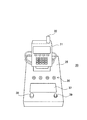
図1に、本実施形態の無線検針メータ10と情報処理端末20の関係を模式化した図を示す。無線検針メータ10は通常のガスメータ11に、無線通信装置14を取り付けたものである。ガスメータ11の検針は従来、検針員がカウンタ窓12に示される数字を目視で確認し、ガスの使用量を把握すると言った手法で検針が行われてきた。ただし、ガスメータ11に無線通信装置14を取り付ける事で、情報処理端末20との通信で検針が可能となっている。
FIG. 1 schematically shows the relationship between the wireless meter-reading
情報処理端末20は、液晶画面22とキーボード23、プリント出力部24を備えた検針用の専用端末であり、無線通信モジュール21を備えている。無線通信モジュール21は無線通信装置14と特定小電力無線の電波帯域を使用して通信できる。ガスメータ11からの検針データは、情報処理端末20からの通信指令に無線検針メータ10がアンサーバックする形で、情報処理端末20が取得し、図示しない記憶領域にデータが保管される。また、必要に応じてプリント出力部24からデータを出力することが可能である。
The
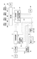
図2に、電波受信機30の概略図を示す。電波受信機30は、ハンディー無線機31でありアンテナ32を備えたハンディータイプの特定小電力無線機である。電波受信機30と接続するのは強度表示器35であり、強度表示器35は電波強度表示ランプ36と電波強度表示画面37を備えている。電波強度表示ランプ36はLEDランプを利用した表示部であり受信した電波強度を段階的に表示する。電波強度表示画面37では数字で電波強度を表示する。バックライトスイッチ38は電波強度表示画面37のバックライトを点灯させるスイッチである。リセットスイッチ39は表示をリセットするスイッチである。
FIG. 2 shows a schematic diagram of the
図3に、強度表示器に関するブロック図を示す。電波強度表示ランプ36は青色ランプ36a、緑色ランプ36b、黄色ランプ36c、及び赤色ランプ36dの4つからなり、それぞれ所定の電波強度を超えると点灯される。電波強度表示ランプ36と電波強度表示画面37は接続され、電波強度表示ランプ36及び電波強度表示画面37の制御を行うのが、電波強度表示画面37に接続されるデータ処理部40である。バックライトスイッチ38は電波強度表示画面37に接続され、リセットスイッチ39はデータ処理部40に接続されている。
FIG. 3 shows a block diagram relating to the intensity indicator. The radio wave
データ処理部40は増幅処理部41と電源スイッチ43とに接続され、増幅処理部41はDC/DCコンバータ42と電源スイッチ43及び切替回路48を介して入力47に接続されている。また、増幅処理部41は切替回路48を介して乾電池電圧監視回路45にも接続されている。入力47はハンディー無線機31からの信号を入力する部分で、入力47とハンディー無線機31とは信号を受け渡しが可能なように電気的に接続されている。電源スイッチ43は電池ケース44と接続され、電池ケース44には図示しない電池が納められている。電源スイッチ43に繋がる回路には、乾電池電圧監視回路45が接続されており、電池ケース44に納められる電池の電圧を監視している。電池レベルに関しては、図示しない確認ボタンを押すと電波強度表示ランプ36を使用して表示できるように設計されている。
The
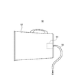
図4に、指向性アンテナの側面図を示す。指向性アンテナ50は、金属製の円筒体52の中央にアンテナ部51が備えられたものである。アンテナ部51には接続線53が備えられ接続線53はアンテナ32の代わりにハンディー無線機31に接続される。ハンディー無線機31に指向性アンテナ50を接続することで、ハンディー無線機31で検出される電波に指向性を持たせることが出来るため、範囲の特定が容易になる。
FIG. 4 shows a side view of the directional antenna. The
本実施形態の無線検針メータ位置検知方法の構成は上記に示したものであり、次に、運用手順について説明する。 The configuration of the wireless metering meter position detection method of the present embodiment is as described above, and the operation procedure will be described next.
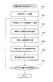
図5に、方向特定手順に関するフローチャートを示す。図6に、詳細位置の特定手順に関するフローチャートを示す。第1特定手順に対応する方向特定手順は、無線検針メータ10の大まかな位置を特定する手段である。検針員が現場に行ったときに目視で無線検針メータ10が確認できないようなケースにおいて、電波受信機30を用いた無線検針メータ10の検出を行う。
FIG. 5 shows a flowchart regarding the direction specifying procedure. FIG. 6 shows a flowchart regarding the detailed position specifying procedure. The direction specifying procedure corresponding to the first specifying procedure is means for specifying a rough position of the wireless meter-reading
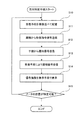
まず、S10では、受信手段となる電波受信機30を複数並べて配置する。方向特定手順は第1特定手順に該当する。本実施形態では電波受信機30を4セット用意し、横一列に並べることとする。図7に、実験した際の模式平面図を示す。便宜的に4つの電波受信機30をそれぞれ第1電波受信機30a、第2電波受信機30b、第3電波受信機30c及び第4電波受信機30dとする。そしてS11へと移行する。
First, in S10, a plurality of
S11では、親機からの発信指令信号を送信する。親機である情報処理端末20から、無線検針メータ10の有する無線通信装置14に対して信号を出すように指示をする。この親機からの信号は約20秒程度連続で送出される。この際、システムによっては中継機を必要とする場合もあるが、ここではその説明を省略する。要は情報処理端末20からの指示が無線検針メータ10に伝えられ、アンサーバック信号として通知信号が返されるプロセスがあれば良い。そしてS12に移行する。
In S11, a transmission command signal from the parent device is transmitted. The
S12では、子機から通知信号を送信する。親機である情報処理端末20から発信指令信号が送られると、それに応えるように子機となる無線検針メータ10に備えられた無線通信装置14から通知信号が出される。この際の通知信号は、1分間隔に2回、0.5秒ずつの信号が返されるのみである。そしてS13に移行する。
In S12, a notification signal is transmitted from the slave unit. When a transmission command signal is sent from the
S13では、受信手段により通知信号を受信する。受信手段となる電波受信機30は、第1電波受信機30a乃至第4電波受信機30dがそれぞれの配置された位置で信号を受け取り、この信号を電界強度として換算する。増幅処理部41で適宜増幅された信号は、データ処理部40にて電界強度に変換される。そしてS14に移行する。
In S13, the notification signal is received by the receiving means. The
S14では、信号強度を表示手段で表示する。表示手段は電波受信機30に設けられた電波強度表示画面37であり、電界強度(bB)に変換して電波強度表示画面37及び電波強度表示ランプ36にて表示する。これにより、第1電波受信機30a乃至第4電波受信機30dがそれぞれ受信した電波の電界強度をそれぞれの電波強度表示ランプ36及び電波強度表示画面37に示される。そしてS15に移行する。
In S14, the signal intensity is displayed on the display means. The display means is a radio wave
S15では、メータの位置が特定可能かを判断する。S14にて第1電波受信機30a乃至第4電波受信機30dのそれぞれの電界強度が表示されているので、これらを見比べて最も電界強度が強いアンテナを特定し、このアンテナを基準として電波受信機30の配置を再度見直す。図7では、第2電波受信機30bの電波強度表示ランプ36及び電波強度表示画面37が最も強い電界強度を示すことになるので、この付近に無線検針メータ10があると言うことになる。また、第1電波受信機30aの方が第3電波受信機30cよりも電界強度が高くなる。よって、第1電波受信機30aと第2電波受信機30bとの間で、第2電波受信機30b寄りの位置に無線検針メータ10がある事が分かる。また、電界強度は無線通信装置14からの距離の二乗に比例して変化するので、ある程度の距離も把握が可能である。この状態で無線検針メータ10の位置が特定可能であれば特定手段を終了し、特定可能でなければS10へ移行する。
In S15, it is determined whether the meter position can be specified. Since the electric field strength of each of the first
S10では、電波受信機30の位置を変更するが、前回行った第1電波受信機30a乃至第4電波受信機30dの測定結果を参考に第1電波受信機30a乃至第4電波受信機30dのハンディー無線機31を移動させる。そして、再び測定を繰り返すことで、無線検針メータ10の大体の位置を把握することが可能となる。
In S10, the position of the
次に詳細位置の特定について説明する。詳細位置の特定手順は第2特定手順に該当する。S21では、指向性アンテナの接続を行う。電波受信機30のハンディー無線機31には、図2に示すようなアンテナ32が取り付けられているが、このタイプのダイポールアンテナは指向性に乏しく、細かい位置の特定には向かない。そこで、更に指向性を高めるために図4に示すような指向性アンテナ50をハンディー無線機31に取り付ける。こうすることで、円筒体52の開口方向からの信号を受信できる代わりに、その他の方向からの信号を遮断できる。
Next, specification of the detailed position will be described. The detailed position specifying procedure corresponds to the second specifying procedure. In S21, a directional antenna is connected. An
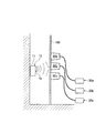
S22では、指向性アンテナを複数並べて配置する。指向性アンテナ50は接続線53でハンディー無線機31に接続されているため、指向性アンテナ50だけを壁にくっつけて複数並べて配置するような運用が可能である。図8に、指向性アンテナ50を縦に並べた様子を断面図に示す。第1指向性アンテナ50aと第2指向性アンテナ50bと第3指向性アンテナ50cは縦に並べられている。第1指向性アンテナ50aは第1電波受信機30aと接続され、第2指向性アンテナ50bは第2電波受信機30bと接続され、第3指向性アンテナ50cは第3電波受信機30cと接続されている。このような状態で、指向性アンテナ50を保持する。そしてS23に移行する。
In S22, a plurality of directional antennas are arranged side by side. Since the
S23では、親機から発信指令信号を送信する。親機である情報処理端末20から発信指令信号を送信することで、子機である無線検針メータ10の備える無線通信装置14に対してアンサーバックをするように指令をする。そしてS24に移行する。S24では、子機から通知信号を送信する。情報処理端末20からの信号に応えて無線通信装置14から通知信号が出される。そしてS25に移行する。
In S23, a transmission command signal is transmitted from the parent device. By transmitting a transmission command signal from the
S25では、受信手段により通知信号を受信する。受信手段である電波受信機30により、無線通信装置14からの通知信号を受信する。電波受信機30は図8に示すように第1電波受信機30a乃至第3電波受信機30cの3つを使用しており、これらがそれぞれ指向性アンテナ50で受信した信号を電波受信機30で取得する。そしてS26に移行する。
In S25, the notification signal is received by the receiving means. A notification signal from the
S26では、信号強度を表示手段で表示する。表示手段である電波強度表示ランプ36及び電波強度表示画面37では、増幅処理部41で適宜増幅されデータ処理部40にて電界強度に変換されたデータが示される。これにより、第1電波受信機30a乃至第3電波受信機30cがそれぞれ受信した電波の電界強度をそれぞれの電波強度表示ランプ36及び電波強度表示画面37に示されることになる。そしてS27に移行する。
In S26, the signal intensity is displayed on the display means. In the radio wave
S27では、メータの位置が特定可能かを判断する。第1指向性アンテナ50a乃至第3指向性アンテナ50cの内、無線検針メータ10に最も近い第2指向性アンテナ50bが一番強い信号を受信し、第2電波受信機30bの有する電波強度表示ランプ36及び電波強度表示画面37が他の電波受信機30よりも高い値を示している。このため、第2指向性アンテナ50bの近くに無線検針メータ10があることが確認できる。なお、メータの高さが特定可能であればそのまま処理を終了し、特定ができなければS22に移行し、第2指向性アンテナ50bの位置を参考に再度詳細位置の特定手順のプロセスを行う。
In S27, it is determined whether the meter position can be specified. Of the first
本実施形態の無線検針メータ位置検知方法は上記構成であるので、以下に説明するような作用及び効果を奏する。 Since the wireless metering meter position detection method of the present embodiment has the above-described configuration, the following operations and effects are achieved.
まず、本実施形態の無線検針メータ位置検知方法によって、無線検針メータ10の位置特定が容易になる点が挙げられる。本実施形態の無線検針メータ位置検知方法は、無線を利用して検針データを通知する無線通信装置14と、無線通信装置14に通知信号を発信するように発信指令信号を送る情報処理端末20と、無線通信装置14から通知された通知信号を取得する為のアンテナ32と接続する電波受信機30と、電波受信機30から通知信号のデータを取得し、受信強度を記録するデータ処理部40と、受信強度を示す電波強度表示ランプ36及び電波強度表示画面37を備えた、無線検針メータ位置検出方法であり、第1特定手順と第2特定手順を用いて目的の無線検針メータ10の位置を探し出すことが可能である。
First, the wireless metering meter position detection method of the present embodiment makes it easy to specify the position of the
方向特定手順である第1特定手順として、アンテナ32を備えた電波受信機30を複数並べ、無線通信装置14から発信指令信号を出し、発信指令信号に応える通知信号を電波受信機30でそれぞれ受信し、電波強度表示ランプ36及び電波強度表示画面37でそれぞれのアンテナ32が受信した信号強度を表示し、無線通信装置14の存在する方角を特定する。そして、詳細位置の特定手順である第2特定手順として、指向性を高める為の円筒体を備えた指向性アンテナ50を、電波受信機30に接続し、指向性アンテナ50を備えた電波受信機30を複数並べ、情報処理端末20から発信指令信号を出し、発信指令信号に応える通知信号を、電波受信機30でそれぞれ受信し、電波強度表示ランプ36及び電波強度表示画面37でそれぞれの指向性アンテナ50が受信した信号強度を表示し、無線通信装置14の存在する位置を特定する。
As a first identification procedure that is a direction identification procedure, a plurality of
無線検針メータ10に用いている無線通信装置14は、課題などで示した通り、省電力を求めて、所定の間隔で非常に短い時間しか信号が返ってこない。したがって、複数の電波受信機30を用いてそれぞれが受信した電界強度を測定することで、大まかな無線検針メータ10の位置が特定できることになる。この構成は、情報処理端末20が中継器を使って無線通信装置14に信号を送るケースでも同様の処理で、無線検針メータ10の位置を特定することが出来る。中継器側からは弱い返信信号があり、無線通信装置14側からはそれよりも強い返信信号が返ってくるので、サンプリング周期を短くして複数回のサンプリングを行い、最も強い値を取得した電界強度として電波強度表示ランプ36及び電波強度表示画面37に表示させる。
The
前述した図7に示される様な合板壁100の向こう側に無線検針メータ10が設置されているようなケースであっても、第1電波受信機30a乃至第4電波受信機30dでそれぞれ電波を受信する。そして、作業員がそれぞれの電波強度表示ランプ36及び電波強度表示画面37に示される数値を参考に、第1電波受信機30a乃至第4電波受信機30dのうちどれが最も無線検針メータ10に近いかを判断する。必要に応じてこの第1特定手順を複数回繰り返すことで、無線検針メータ10の大まかな位置が把握出来ることになる。
Even in the case where the
さらに第2特定手順で詳細位置を特定することが出来る。指向性アンテナ50によってアンテナ部51で取得できる電波の方向は絞られる。よって、合板壁100のどの辺りの高さに無線検針メータ10が設置されているか、を第1特定手順よりも詳細に把握することが出来る。なお、図8では縦に指向性アンテナ50を並べているが、任意の位置に指向性アンテナ50を配置することで詳細位置を判断することが可能である。例えば横一列に並べたり斜めに配置したりしても、ガスメータ11の最も近くにある指向性アンテナ50が、一番強い電波を受信する点には変わりがないので、縦に並べたときと同様に無線検針メータ10の位置の特定が可能となる。要は指向性アンテナ50によって受信範囲の指向性が高められるので、これを利用して無線検針メータ10の詳細位置が特定できれば、特に配置に拘る必要は無い。そして、第2特定手順を繰り返すことで、無線検針メータ10の詳細位置が把握できる。
Further, the detailed position can be specified by the second specifying procedure. The direction of the radio wave that can be acquired by the
課題にも示した通り、無線検針メータ10の設置場所は、無線通信が出来るが故に見失われるケースが出てきており、場合によってはその前に合板壁100のような壁が作られてしまうケースもある。こうなると、ガスメータ11の交換作業に行った作業者は無線検針メータ10を探すことが出来なくなってしまう。
As indicated in the problem, there are cases where the location of the
合板壁100は客側の設備であるため、安易に撤去することが出来ない。また、破損した部分は作業者側の負担で修繕する必要があるため、破損箇所は最小限に留めたいという要望がある。このようなケースにおいても、本実施形態で示した無線検針メータ位置検知方法によって、スムーズに無線検針メータ10を発見することが可能となる。発見後は合板壁100に必要最小限の穴を開けて、無線検針メータ10の交換作業を行い、その後に合板壁100の修復を行えば良いので、無線検針メータ10の位置特定精度は高い方が望ましいが、無線検針メータ位置検知方法によって、それが実現可能となる。
Since the
なお、電波強度表示ランプ36については、乾電池電圧監視回路45によって電池ケース44に納められている乾電池の電圧を監視しており、切替回路48を切り替えることで、乾電池の電圧レベルを表示することにも使用が可能な構成となっている。
Regarding the radio wave
以上、本実施形態に則して発明を説明したが、この発明は前記実施形態に限定されるものではなく、発明の趣旨を逸脱することのない範囲で構成の一部を適宜変更することにより実施することもできる。 Although the invention has been described according to the present embodiment, the invention is not limited to the embodiment, and by appropriately changing a part of the configuration without departing from the spirit of the invention. It can also be implemented.
例えば、情報処理端末20と電波受信機30は必要に応じて一体型のユニットとすることを妨げない。また、電波受信機30に関しても第1電波受信機30a乃至第4電波受信機30dの機能を集約して、アンテナ32のみ分離して配置できるような構成とすることを妨げない。また、無線通信装置14を特定する際に方向特定手順に4つの電波受信機30を用い、詳細位置の特定手順に3つの電波受信機30を用いるよう説明しているが、この個数を変更することを妨げない。ただし、現場の作業員が使用することを前提にしたシンプルな構成であることが望ましい。
For example, the
10 無線検針メータ
11 ガスメータ
12 カウンタ窓
14 無線通信装置
20 情報処理端末
30 電波受信機
31 ハンディー無線機
32 アンテナ
35 強度表示器
36 電波強度表示ランプ
37 電波強度表示画面
50 指向性アンテナ
51 アンテナ部
52 円筒体
53 接続線
DESCRIPTION OF
Claims (1)
前記子機に通知信号を発信するように発信指令信号を送る親機と、
前記子機から通知された前記通知信号を取得する為のアンテナと接続する受信手段と、前記受信手段から前記通知信号のデータを取得し、受信強度を記録する記憶手段と、前記受信強度を示す表示手段と、を備え、
第1特定手順として、
前記アンテナを備えた前記受信手段を複数並べ、
前記親機から前記発信指令信号を出し、
前記発信指令信号に応える前記通知信号を前記受信手段でそれぞれ受信し、前記表示手段でそれぞれの前記アンテナが受信した信号強度を表示し、前記子機の存在する方角を特定し、
前記信号強度が最も高かった前記アンテナの位置を参考に、前記第1特定手順を繰り返すことで、前記子機の大体の位置を把握し、
第2特定手順として、
指向性を高める為の円筒体を備えた指向性アンテナを、前記受信手段に接続し、前記指向性アンテナを備えた前記受信手段を複数並べ、
前記親機から前記発信指令信号を出し、
前記発信指令信号に応える前記通知信号を、前記受信手段でそれぞれ受信し、前記表示手段でそれぞれの前記指向性アンテナが受信した信号強度を表示し、前記子機の存在する位置を特定し、
前記第2特定手順で前記子機の存在する位置を特定できなかった場合に、前記信号強度が最も高かった前記指向性アンテナの位置を参考に、前記第2特定手順を繰り返すことで、前記子機の位置を把握すること、
を特徴とする無線検針メータ位置検知方法。 A handset that notifies the meter reading data wirelessly;
A master unit that sends a transmission command signal so as to transmit a notification signal to the slave unit;
Receiving means connected to an antenna for acquiring the notification signal notified from the slave unit, storage means for acquiring data of the notification signal from the receiving means and recording the reception intensity, and indicating the reception intensity Display means,
As the first specific procedure,
Arranging a plurality of the receiving means provided with the antenna,
The transmission command signal is issued from the master unit,
The notification signal corresponding to the transmission command signal is received by the receiving unit, the signal strength received by each antenna is displayed by the display unit, and the direction in which the slave unit exists is specified,
By referring to the position of the antenna having the highest signal strength, by repeating the first specific procedure, grasp the approximate position of the slave unit,
As a second specific procedure,
A directional antenna provided with a cylindrical body for enhancing directivity is connected to the receiving means, and a plurality of the receiving means provided with the directional antenna are arranged,
The transmission command signal is issued from the master unit,
The notification signal in response to the transmission command signal is received by the receiving unit, the signal strength received by the directional antenna is displayed by the display unit, and the position where the slave unit exists is specified,
When the position where the slave is present cannot be specified by the second specifying procedure, the child specifying unit repeats the second specifying procedure with reference to the position of the directional antenna having the highest signal strength. Knowing the position of the machine,
A method for detecting the position of a wireless meter-reading meter.
Priority Applications (1)
| Application Number | Priority Date | Filing Date | Title |
|---|---|---|---|
| JP2011228902A JP5839552B2 (en) | 2011-10-18 | 2011-10-18 | Wireless metering meter position detection method |
Applications Claiming Priority (1)
| Application Number | Priority Date | Filing Date | Title |
|---|---|---|---|
| JP2011228902A JP5839552B2 (en) | 2011-10-18 | 2011-10-18 | Wireless metering meter position detection method |
Publications (2)
| Publication Number | Publication Date |
|---|---|
| JP2013088282A JP2013088282A (en) | 2013-05-13 |
| JP5839552B2 true JP5839552B2 (en) | 2016-01-06 |
Family
ID=48532333
Family Applications (1)
| Application Number | Title | Priority Date | Filing Date |
|---|---|---|---|
| JP2011228902A Active JP5839552B2 (en) | 2011-10-18 | 2011-10-18 | Wireless metering meter position detection method |
Country Status (1)
| Country | Link |
|---|---|
| JP (1) | JP5839552B2 (en) |
Family Cites Families (7)
| Publication number | Priority date | Publication date | Assignee | Title |
|---|---|---|---|---|
| JPH0313743Y2 (en) * | 1986-06-06 | 1991-03-28 | ||
| JPS6466581A (en) * | 1987-09-08 | 1989-03-13 | Susumu Sakuma | Guarding method performed through transmission and reception of emergency signal |
| JPH04207702A (en) * | 1990-11-30 | 1992-07-29 | Maspro Denkoh Corp | Primary radiator for circularly polarized wave |
| JP2000285355A (en) * | 1999-03-31 | 2000-10-13 | Osaka Gas Co Ltd | Position detecting device |
| JP2006350594A (en) * | 2005-06-15 | 2006-12-28 | Matsushita Electric Ind Co Ltd | Automatic wireless measuring device and its prowlum |
| JP2008177779A (en) * | 2007-01-17 | 2008-07-31 | National Institute Of Information & Communication Technology | Position detection system |
| US8242931B2 (en) * | 2009-09-18 | 2012-08-14 | Elster Electricity, Llc | Mobile meter reading for locating stolen utility meters |
-
2011
- 2011-10-18 JP JP2011228902A patent/JP5839552B2/en active Active
Also Published As
| Publication number | Publication date |
|---|---|
| JP2013088282A (en) | 2013-05-13 |
Similar Documents
| Publication | Publication Date | Title |
|---|---|---|
| CN203113804U (en) | Concrete vibrator | |
| US20140062719A1 (en) | Using smart meters as reliable crowd-sourcing agents | |
| CN101753228B (en) | Method and device for detecting angle state of antenna in cell | |
| JP5616702B2 (en) | GNSS analysis system, GNSS analysis apparatus, and GNSS analysis program | |
| CN103973514A (en) | Intelligent patrol positioning collection system of transformer substation | |
| JP2009245109A (en) | Equipment-monitoring system using radio communication and measuring instrument using the same | |
| KR101211566B1 (en) | Sensor module for underground water, management system using the same and monitering method for the status of underground water | |
| JP2020187534A (en) | Radio wave intensity monitoring system | |
| JP5839552B2 (en) | Wireless metering meter position detection method | |
| JP2007018126A (en) | Collapse monitoring system | |
| US8362917B2 (en) | Device for determining communications parameters and method of operation | |
| CN202904009U (en) | System for realizing relative positioning of object by using radio frequency technology and ultrasound technology | |
| CN105241368A (en) | Automatic detection instrument for thickness of floor | |
| JP6406995B2 (en) | Wireless telemeter system and wireless communication device | |
| JP5098634B2 (en) | Wireless communication system, control device, and program | |
| JP2012134639A (en) | Method for selecting communication route of radio communication system | |
| JP2019030138A (en) | Watt-hour meter | |
| JP2010108417A (en) | Radio meter reading system and handy terminal for radio meter reading | |
| JP6167085B2 (en) | Wireless measurement system, wireless sensor terminal, and device management method | |
| CN204948084U (en) | A kind of micropower wireless communication module automatic batch detection system | |
| JP5370078B2 (en) | Wireless meter reading device | |
| CN218412856U (en) | Tower grounding comprehensive detection device | |
| JP2015111749A (en) | Terminal and diagnostic device having self-diagnostic function by wireless power supply | |
| JP2014155197A (en) | Communication device, power meter, and program | |
| CN101782779A (en) | Debugging method of monitoring system |
Legal Events
| Date | Code | Title | Description |
|---|---|---|---|
| A621 | Written request for application examination |
Free format text: JAPANESE INTERMEDIATE CODE: A621 Effective date: 20140730 |
|
| A977 | Report on retrieval |
Free format text: JAPANESE INTERMEDIATE CODE: A971007 Effective date: 20150529 |
|
| A131 | Notification of reasons for refusal |
Free format text: JAPANESE INTERMEDIATE CODE: A131 Effective date: 20150609 |
|
| A521 | Request for written amendment filed |
Free format text: JAPANESE INTERMEDIATE CODE: A523 Effective date: 20150630 |
|
| TRDD | Decision of grant or rejection written | ||
| A01 | Written decision to grant a patent or to grant a registration (utility model) |
Free format text: JAPANESE INTERMEDIATE CODE: A01 Effective date: 20151104 |
|
| A61 | First payment of annual fees (during grant procedure) |
Free format text: JAPANESE INTERMEDIATE CODE: A61 Effective date: 20151106 |
|
| R150 | Certificate of patent or registration of utility model |
Ref document number: 5839552 Country of ref document: JP Free format text: JAPANESE INTERMEDIATE CODE: R150 |
|
| R250 | Receipt of annual fees |
Free format text: JAPANESE INTERMEDIATE CODE: R250 |
|
| R250 | Receipt of annual fees |
Free format text: JAPANESE INTERMEDIATE CODE: R250 |
|
| S111 | Request for change of ownership or part of ownership |
Free format text: JAPANESE INTERMEDIATE CODE: R313111 |
|
| R350 | Written notification of registration of transfer |
Free format text: JAPANESE INTERMEDIATE CODE: R350 |
|
| R250 | Receipt of annual fees |
Free format text: JAPANESE INTERMEDIATE CODE: R250 |
|
| R250 | Receipt of annual fees |
Free format text: JAPANESE INTERMEDIATE CODE: R250 |