JP5838642B2 - Water treatment system - Google Patents
Water treatment system Download PDFInfo
- Publication number
- JP5838642B2 JP5838642B2 JP2011171624A JP2011171624A JP5838642B2 JP 5838642 B2 JP5838642 B2 JP 5838642B2 JP 2011171624 A JP2011171624 A JP 2011171624A JP 2011171624 A JP2011171624 A JP 2011171624A JP 5838642 B2 JP5838642 B2 JP 5838642B2
- Authority
- JP
- Japan
- Prior art keywords
- water
- pretreatment
- line
- pressure
- unit
- Prior art date
- Legal status (The legal status is an assumption and is not a legal conclusion. Google has not performed a legal analysis and makes no representation as to the accuracy of the status listed.)
- Active
Links
- XLYOFNOQVPJJNP-UHFFFAOYSA-N water Substances O XLYOFNOQVPJJNP-UHFFFAOYSA-N 0.000 title claims description 268
- 239000012528 membrane Substances 0.000 claims description 56
- 238000000926 separation method Methods 0.000 claims description 16
- 238000011144 upstream manufacturing Methods 0.000 claims description 16
- 238000001223 reverse osmosis Methods 0.000 claims description 15
- 238000001514 detection method Methods 0.000 claims description 11
- 239000012466 permeate Substances 0.000 claims description 10
- 238000007781 pre-processing Methods 0.000 claims description 8
- 230000005856 abnormality Effects 0.000 claims description 7
- 230000005540 biological transmission Effects 0.000 claims description 7
- 238000007599 discharging Methods 0.000 claims description 2
- OKTJSMMVPCPJKN-UHFFFAOYSA-N Carbon Chemical compound [C] OKTJSMMVPCPJKN-UHFFFAOYSA-N 0.000 description 22
- 238000000034 method Methods 0.000 description 14
- 230000008569 process Effects 0.000 description 12
- 238000001914 filtration Methods 0.000 description 10
- 238000011045 prefiltration Methods 0.000 description 10
- 230000007423 decrease Effects 0.000 description 5
- 238000004519 manufacturing process Methods 0.000 description 4
- 238000004364 calculation method Methods 0.000 description 3
- 239000008233 hard water Substances 0.000 description 3
- 239000008239 natural water Substances 0.000 description 3
- 239000000126 substance Substances 0.000 description 3
- 230000008859 change Effects 0.000 description 2
- 238000010586 diagram Methods 0.000 description 2
- 239000003673 groundwater Substances 0.000 description 2
- 230000035699 permeability Effects 0.000 description 2
- 238000002407 reforming Methods 0.000 description 2
- 150000003839 salts Chemical class 0.000 description 2
- 239000008399 tap water Substances 0.000 description 2
- 235000020679 tap water Nutrition 0.000 description 2
- NWUYHJFMYQTDRP-UHFFFAOYSA-N 1,2-bis(ethenyl)benzene;1-ethenyl-2-ethylbenzene;styrene Chemical compound C=CC1=CC=CC=C1.CCC1=CC=CC=C1C=C.C=CC1=CC=CC=C1C=C NWUYHJFMYQTDRP-UHFFFAOYSA-N 0.000 description 1
- BHPQYMZQTOCNFJ-UHFFFAOYSA-N Calcium cation Chemical compound [Ca+2] BHPQYMZQTOCNFJ-UHFFFAOYSA-N 0.000 description 1
- ZAMOUSCENKQFHK-UHFFFAOYSA-N Chlorine atom Chemical compound [Cl] ZAMOUSCENKQFHK-UHFFFAOYSA-N 0.000 description 1
- JLVVSXFLKOJNIY-UHFFFAOYSA-N Magnesium ion Chemical compound [Mg+2] JLVVSXFLKOJNIY-UHFFFAOYSA-N 0.000 description 1
- 230000008901 benefit Effects 0.000 description 1
- 230000004397 blinking Effects 0.000 description 1
- 229910001424 calcium ion Inorganic materials 0.000 description 1
- 239000003729 cation exchange resin Substances 0.000 description 1
- 239000000460 chlorine Substances 0.000 description 1
- 229910052801 chlorine Inorganic materials 0.000 description 1
- 238000004140 cleaning Methods 0.000 description 1
- 239000012141 concentrate Substances 0.000 description 1
- 230000000694 effects Effects 0.000 description 1
- 239000012530 fluid Substances 0.000 description 1
- 239000013505 freshwater Substances 0.000 description 1
- 230000006870 function Effects 0.000 description 1
- 239000012535 impurity Substances 0.000 description 1
- 229910001425 magnesium ion Inorganic materials 0.000 description 1
- 239000002861 polymer material Substances 0.000 description 1
- 229910001414 potassium ion Inorganic materials 0.000 description 1
- 238000011084 recovery Methods 0.000 description 1
- 239000004065 semiconductor Substances 0.000 description 1
- 229910001415 sodium ion Inorganic materials 0.000 description 1
- 230000001629 suppression Effects 0.000 description 1
- 239000002351 wastewater Substances 0.000 description 1
Images

Landscapes
- Separation Using Semi-Permeable Membranes (AREA)
Description
本発明は、前処理部と膜分離部とを備えた水処理システムに関する。 The present invention relates to a water treatment system including a pretreatment unit and a membrane separation unit.
半導体の製造工程、電子部品や医療器具の洗浄等においては、不純物を含まない高純度の純水が使用される。この種の純水は、一般に、地下水や水道水等の原水を、濾過装置や硬水軟化装置等の前処理ユニットで前処理した後、逆浸透膜モジュール(以下、「RO膜モジュール」ともいう)で逆浸透膜分離処理することにより製造される。 In the semiconductor manufacturing process, the cleaning of electronic parts and medical instruments, etc., high-purity pure water containing no impurities is used. This type of pure water is generally prepared by pre-treating raw water such as groundwater or tap water with a pretreatment unit such as a filtration device or a water softening device, and then a reverse osmosis membrane module (hereinafter also referred to as “RO membrane module”). It is manufactured by reverse osmosis membrane separation treatment.
高分子材料からなる逆浸透膜は、温度により水透過係数が変化する特性を持つ。具体的には、RO膜モジュールの水透過係数は、前処理された水(以下、「前処理水」ともいう)の温度が低ければ小さくなり、前処理水の温度が高ければ大きくなる。 A reverse osmosis membrane made of a polymer material has a characteristic that the water permeability coefficient changes with temperature. Specifically, the water permeability coefficient of the RO membrane module decreases as the temperature of pretreated water (hereinafter also referred to as “pretreated water”) decreases, and increases as the temperature of the pretreated water increases.
RO膜モジュールに前処理水を送り出す加圧ポンプを一定の運転圧力で運転した場合、前処理水の温度が基準温度よりも低くなると、要求される生産水量に対して製造される透過水(純水)の水量が少なくなる。この場合、需要箇所への供給量が不足する。また、前処理水の温度が基準温度よりも高くなると、要求される生産水量に対して透過水の水量が多くなる。この場合は、前処理ユニットの早期能力低下やRO膜モジュールの一次側膜表面での過濃縮に繋がる。 When the pressure pump that pumps the pretreatment water to the RO membrane module is operated at a constant operating pressure, the permeated water (pure water) produced with respect to the required production water volume when the temperature of the pretreatment water becomes lower than the reference temperature. The amount of water is reduced. In this case, the supply amount to the demand point is insufficient. Further, when the temperature of the pretreatment water becomes higher than the reference temperature, the amount of permeated water increases with respect to the required amount of production water. In this case, it leads to the early capacity | capacitance fall of a pre-processing unit and the overconcentration on the primary side membrane surface of RO membrane module.
そこで、前処理水の温度に関わらず、RO膜モジュールにおける透過水の流量を一定に保つため、流量フィードバック制御を行う水質改質システムが提案されている。この流量フィードバック制御では、RO膜モジュールで製造される透過水の流量が目標値となるように、RO膜モジュールに前処理水を送出する加圧ポンプの駆動周波数がインバータにより制御される(特許文献1参照)。 Therefore, a water quality reforming system that performs flow rate feedback control has been proposed in order to keep the flow rate of permeated water in the RO membrane module constant regardless of the temperature of the pretreatment water. In this flow rate feedback control, the drive frequency of the pressurizing pump that sends the pretreated water to the RO membrane module is controlled by an inverter so that the flow rate of the permeated water produced by the RO membrane module becomes a target value (Patent Literature). 1).
上述した前処理ユニットにおいて、例えば、濾材床に懸濁物質等が蓄積すると、通水抵抗が増加する。前処理ユニットにおいて、通水抵抗が増加すると、加圧ポンプの一次側に供給される前処理水の圧力が低下する。そのため、従来は、前処理ユニットに原水を供給する原水ポンプの運転圧力を、前処理ユニットから送出される前処理水の圧力が低下する分を見込んで高めに設定していた。 In the above-described pretreatment unit, for example, when suspended substances accumulate in the filter medium bed, the water flow resistance increases. In the pretreatment unit, when the water flow resistance increases, the pressure of the pretreatment water supplied to the primary side of the pressure pump decreases. Therefore, conventionally, the operating pressure of the raw water pump that supplies the raw water to the pretreatment unit has been set to be high in anticipation of a decrease in the pressure of the pretreatment water sent from the pretreatment unit.
一方、特許文献1に記載された水質改質システムにおいて、RO膜モジュールで製造された濃縮水は、RO膜モジュールの一次側出口ポートに接続された濃縮水ラインから流出する。その濃縮水ラインには、濃縮水の一部を加圧ポンプの上流側における前処理水ラインに還流させる濃縮水循環ラインと、濃縮水の残部を系外へ排出する濃縮水排水ラインが接続されている。
On the other hand, in the water quality reforming system described in
濃縮水循環ラインに濃縮水を流通させるには、濃縮水循環ラインの一次側(濃縮水ライン側)と二次側(前処理水ライン側)との間に圧力差が必要となる。特に、濃縮水循環ラインに定流量弁を設けた場合には、定流量弁を動作させるために、所定の圧力差が必要となる。そのため、従来は、濃縮水循環ラインが合流する位置よりも上流側の前処理水ラインに減圧弁を設け、濃縮水循環ラインの二次側において、前処理水の圧力を下げていた。 In order to distribute the concentrated water through the concentrated water circulation line, a pressure difference is required between the primary side (the concentrated water line side) and the secondary side (the pretreatment water line side) of the concentrated water circulation line. In particular, when a constant flow valve is provided in the concentrated water circulation line, a predetermined pressure difference is required to operate the constant flow valve. For this reason, conventionally, a pressure reducing valve is provided in the pretreatment water line upstream of the position where the concentrated water circulation line joins, and the pressure of the pretreatment water is lowered on the secondary side of the concentrated water circulation line.
このように、従来の水処理システムにおいては、前処理ユニットの下流側で前処理水を減圧するにもかかわらず、前処理ユニットの上流側に設けられた原水ポンプの運転圧力を本来必要な圧力よりも高く設定していた。このため、原水ポンプにおける消費電力の抑制が課題となっていた。 As described above, in the conventional water treatment system, the operating pressure of the raw water pump provided on the upstream side of the pretreatment unit is set to a pressure which is originally necessary, even though the pretreatment water is decompressed on the downstream side of the pretreatment unit. Was set higher than. For this reason, suppression of power consumption in the raw water pump has been an issue.
従って、本発明は、原水ポンプの消費電力を抑制できる水処理システムを提供することを目的とする。 Therefore, an object of this invention is to provide the water treatment system which can suppress the power consumption of a raw | natural water pump.
本発明は、原水から前処理水を製造する前処理部と、前処理水から透過水を製造する膜分離部と、を含み、前記前処理部は、原水が供給される少なくとも一つの前処理ユニットと、入力された第1駆動周波数に応じた回転速度で駆動され、原水を前記前処理ユニットに向けて供給する原水ポンプと、入力された第1の演算値信号に対応する第1駆動周波数を前記原水ポンプに出力する第1インバータと、前処理水の圧力を検出する圧力検出手段と、前記圧力検出手段の検出圧力値が予め設定された目標圧力値となるように、PIDアルゴリズムにより前記原水ポンプの第1駆動周波数を演算し、当該第1駆動周波数の演算値に対応する前記第1の演算値信号を前記第1インバータに出力する第1制御部と、を備え、前記膜分離部は、供給された前処理水を透過水と濃縮水とに分離する逆浸透膜モジュールと、入力された第2駆動周波数に応じた回転速度で駆動され、前処理水を前記逆浸透膜モジュールに向けて供給する加圧ポンプと、入力された第2の演算値信号に対応する第2駆動周波数を前記加圧ポンプに出力する第2インバータと、透過水の流量を検出する流量検出手段と、前記流量検出手段の検出流量値が予め設定された目標流量値となるように、PIDアルゴリズムにより前記加圧ポンプの第2駆動周波数を演算し、当該第2駆動周波数の演算値に対応する前記第2の演算値信号を前記第2インバータに出力する第2制御部と、を備える水処理システムであって、水処理システムは、原水を前記前処理ユニットに供給する原水ラインと、前記前処理ユニットにより製造された前処理水を前記逆浸透膜モジュールに供給する前処理水ラインと、透過水を前記逆浸透膜モジュールから送出する透過水ラインと、濃縮水を前記逆浸透膜モジュールから送出する濃縮水ラインと、上流側が前記濃縮水ラインに接続されると共に下流側が前記前処理水ラインに接続され、前記濃縮水ラインを流通する濃縮水の一部を前記前処理水ラインにおける前記加圧ポンプよりも上流側に還流させる濃縮水循環ラインと、前記濃縮水ラインを流通する濃縮水の残部を装置外に排出する濃縮水排水ラインと、を備え、前記圧力検出手段は、前記前処理水ラインにおける前記濃縮水循環ラインの接続位置よりも上流側を流通する前処理水の圧力を検出する水処理システムに関する。 The present invention includes a pretreatment unit that produces pretreatment water from raw water, and a membrane separation unit that produces permeate from pretreatment water, wherein the pretreatment unit is at least one pretreatment to which raw water is supplied. A unit, a raw water pump that is driven at a rotational speed corresponding to the input first driving frequency and supplies raw water to the pretreatment unit, and a first driving frequency corresponding to the input first calculation value signal Is output to the raw water pump, pressure detecting means for detecting the pressure of pretreated water, and the PID algorithm so that the detected pressure value of the pressure detecting means becomes a preset target pressure value. It calculates a first driving frequency of the raw water pump, comprising: a first control unit for outputting the first calculation value signal corresponding to the calculated value of the first drive frequency to the first inverter, wherein the membrane separation unit Is supplied A reverse osmosis membrane module that separates the pretreated water into permeated water and concentrated water, and is driven at a rotational speed corresponding to the input second drive frequency, and supplies the pretreated water toward the reverse osmosis membrane module. A pressure pump; a second inverter that outputs a second drive frequency corresponding to the input second operation value signal to the pressure pump; a flow rate detection means for detecting a flow rate of permeated water; and the flow rate detection means. as detected flow value is a preset target flow rate value, calculates a second driving frequency of the pressure pump by the PID algorithm, the second calculation value corresponding to the calculated value of the second driving frequency A water treatment system comprising: a second control unit that outputs a signal to the second inverter, wherein the water treatment system is manufactured by a raw water line that supplies raw water to the pretreatment unit, and the pretreatment unit. Pretreatment water line for supplying the pretreated water to the reverse osmosis membrane module, a permeate line for sending permeate from the reverse osmosis membrane module, and a concentrate water line for sending concentrated water from the reverse osmosis membrane module And the upstream side is connected to the concentrated water line and the downstream side is connected to the pretreated water line, and a part of the concentrated water flowing through the concentrated water line is upstream of the pressurizing pump in the pretreated water line. A concentrated water circulation line that recirculates to the side, and a concentrated water drain line that discharges the remaining portion of the concentrated water flowing through the concentrated water line to the outside of the apparatus, and the pressure detection means is configured to circulate the concentrated water in the pretreatment water line. The present invention relates to a water treatment system that detects the pressure of pretreatment water that circulates upstream from a line connection position .
また、前記前処理部は、外部に情報を伝達する情報伝達部を備え、前記第1制御部は、前記第1インバータから前記原水ポンプに第1駆動周波数を出力したときに、前記圧力検出手段の検出圧力値が、予め設定された第1駆動周波数に対応する圧力範囲を外れる場合には、前記情報伝達部を制御して外部に異常を示す情報を伝達させることが好ましい。 The pretreatment unit includes an information transmission unit that transmits information to the outside, and the first control unit outputs the first driving frequency from the first inverter to the raw water pump. When the detected pressure value is outside the pressure range corresponding to the preset first driving frequency, it is preferable to transmit the information indicating abnormality to the outside by controlling the information transmission unit.
本発明によれば、原水ポンプの消費電力を抑制できる水処理システムを提供することができる。 ADVANTAGE OF THE INVENTION According to this invention, the water treatment system which can suppress the power consumption of a raw | natural water pump can be provided.
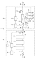
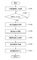
以下、本発明に係る水処理システムについて、図面を参照しながら説明する。本実施形態の水処理システム1は、例えば、淡水から純水を製造する純水製造システムに適用される。図1は、本実施形態に係る水処理システム1の全体構成図である。図2は、第1制御部17が圧力フィードバック制御を実行する場合の処理手順を示すフローチャートである。図3は、第2制御部29が流量フィードバック制御を実行する場合の処理手順を示すフローチャートである。
Hereinafter, a water treatment system according to the present invention will be described with reference to the drawings. The
図1に示すように、本実施形態に係る水処理システム1は、前処理部10と、膜分離部20と、を備える。前処理部10は、原水W1から前処理水W2を製造する設備である。膜分離部20は、前処理水W2から透過水W3と濃縮水W4とを製造する設備である。
As shown in FIG. 1, the
また、水処理システム1は、原水ラインL1と、前処理水ラインL2と、透過水ラインL3と、濃縮水ラインL4と、濃縮水循環ラインL5と、濃縮水排水ライン(第1濃縮水排水ラインL6、第2濃縮水排水ラインL7及び第3濃縮水排水ラインL8)と、を備える。本明細書における「ライン」とは、流路、経路、管路等の流体の流通が可能なラインの総称である。また、図1では、電気的な接続の経路を破線で示す。
The
まず、前処理部10の構成について説明する。
前処理部10は、原水ポンプ11と、第1インバータ12と、活性炭濾過装置13と、硬水軟化装置14と、プレフィルタ装置15と、を備える。また、前処理部10は、圧力検出手段としての圧力センサ16と、第1制御部17と、情報伝達部としての警報部18と、を備える。このうち、活性炭濾過装置13、硬水軟化装置14及びプレフィルタ装置15は、それぞれ前処理ユニットとして機能する。
First, the configuration of the preprocessing
The
原水ラインL1の上流側の端部は、原水W1の供給源(不図示)に接続されている。一方、原水ラインL1の下流側の端部は、活性炭濾過装置13に接続されている。
The upstream end of the raw water line L1 is connected to a supply source (not shown) of the raw water W1. On the other hand, the downstream end of the raw water line L <b> 1 is connected to the activated
原水ポンプ11は、供給源から供給された水道水や地下水等の原水W1を吸入し、活性炭濾過装置13に向けて吐出する装置である。原水ポンプ11は、原水ラインL1に設けられている。原水ポンプ11は、第1インバータ12(後述)と電気的に接続されている。原水ポンプ11には、第1インバータ12から周波数が変換された駆動電力が供給される。原水ポンプ11は、入力された駆動周波数に応じた回転速度で駆動される。
The raw water pump 11 is a device that sucks raw water W1 such as tap water or groundwater supplied from a supply source and discharges the raw water W1 toward the activated
第1インバータ12は、原水ポンプ11に周波数が変換された駆動電力を供給する電気回路である。第1インバータ12は、第1制御部17と電気的に接続されている。第1インバータ12には、第1制御部17から電流値信号が入力される。第1インバータ12は、入力された電流値信号に対応する駆動周波数を原水ポンプ11に出力する。
The
活性炭濾過装置13、硬水軟化装置14及びプレフィルタ装置15からなる前処理ユニット群は、原水W1から前処理水W2を製造する設備である。
活性炭濾過装置13は、原水W1に含まれる残留塩素を、粒状の活性炭からなる濾材床において除去する。
硬水軟化装置14は、原水W1に含まれる硬度成分(カルシウムイオン及びマグネシウムイオン)を、陽イオン交換樹脂床(不図示)においてナトリウムイオン(又はカリウムイオン)に置換する。
プレフィルタ装置15は、活性炭濾過装置13及び硬水軟化装置14で除去できない微細な懸濁物質を、ワインドフィルタ等で捕集する。
The pretreatment unit group including the activated
The activated
The
The
圧力センサ16は、プレフィルタ装置15の下流側において、前処理水W2の圧力を検出する機器である。圧力センサ16は、接続部J1において、前処理水ラインL2に接続されている。圧力センサ16は、第1制御部17と電気的に接続されている。圧力センサ16で検出された前処理水W2の圧力(以下、「検出圧力値」ともいう)は、第1制御部17へ検出信号として送信される。
The
第1制御部17は、CPU及びメモリを含むマイクロプロセッサ(不図示)により構成される。第1制御部17は、圧力センサ16の検出圧力値が予め設定された目標圧力値となるように、原水ポンプ11を駆動するための第1駆動周波数を演算し、当該第1駆動周波数の演算値に対応する電流値信号を第1インバータ12に出力する(以下、「圧力フィードバック制御」ともいう)。第1制御部17による圧力フィードバック制御については後述する。
The
また、第1制御部17は、第1インバータ12から原水ポンプ11に第1駆動周波数を出力したときに、圧力センサ16の検出圧力値が、予め設定された第1駆動周波数に対応する圧力範囲を外れる場合には、警報部18(後述)を制御して警報音を発生させる。
Moreover, when the
警報部18は、システムの管理者に対し異常を警報音により通知する設備である。警報部18は、第1制御部17と電気的に接続されている。警報部18は、第1制御部17から送信された警報制御信号により警報音を発生する。
The
ここで、前処理部10の第1制御部17による圧力フィードバック制御を、図2を参照して説明する。図2に示すフローチャートの処理は、水処理システム1の運転中において、繰り返し実行される。
Here, the pressure feedback control by the
図2に示すステップST101において、第1制御部17は、前処理水W2の目標圧力値P´を取得する。この目標圧力値P´は、例えば、システムの管理者がユーザーインターフェース(不図示)を介して第1制御部17のメモリに入力した設定値である。
In step ST101 shown in FIG. 2, the
ステップST102において、第1制御部17は、内部のタイマ(不図示)による計時tが制御周期である100msに達したか否かを判定する。このステップST102において、第1制御部17により、タイマによる計時が100msに達した(YES)と判定された場合に、処理はステップST103へ移行する。また、ステップST102において、第1制御部17により、タイマによる計時が100msに達していない(NO)と判定された場合に、処理はステップST102へ戻る。
In step ST102, the
ステップST103(ステップST102:YES判定)において、第1制御部17は、圧力センサ16で検出された前処理水W2の検出圧力値Pを取得する。
In step ST103 (step ST102: YES determination), the
ステップST104において、第1制御部17は、ステップST103で取得した検出圧力値(フィードバック値)PとステップST101で取得した目標圧力値P´との偏差がゼロとなるように、速度形デジタルPIDアルゴリズムにより操作量U1を演算する。なお、速度形デジタルPIDアルゴリズムでは、制御周期(100ms)毎に操作量の変化分を演算し、これを前回の操作量に加算することで今回の操作量を決定する。
In step ST104, the
ステップST105において、第1制御部17は、操作量U1、目標圧力値P´及び原水ポンプ11の最大駆動周波数(50Hz又は60Hzの設定値)に基づいて、原水ポンプ11の駆動周波数F1を演算する。
ステップST106において、第1制御部17は、駆動周波数F1の演算値を、対応する電流値信号(4〜20mA)に変換する。
In Step ST105, the
In step ST 106, the
ステップST107において、第1制御部17は、変換した電流値信号を第1インバータ12に出力する。なお、ステップST107において、第1制御部17が電流値信号を第1インバータ12へ出力すると、第1インバータ12は、入力された電流値信号に対応する周波数に変換された駆動電力を原水ポンプ11に供給する。その結果、原水ポンプ11は、第1インバータ12から入力された駆動周波数に応じた回転速度で駆動される。
In step ST <b> 107, the
ステップST108において、第1制御部17は、ステップST103で取得した検出圧力値Pが、予め設定された第1駆動周波数に対応する圧力範囲(以下、「基準圧力範囲」ともいう)を外れるか否かを判定する。このステップST108において、第1制御部17により、検出圧力値が基準圧力範囲を外れる(YES)と判定された場合に、処理はステップST109へ移行する。また、ステップST108において、第1制御部17により、検出圧力値が基準圧力範囲内である(NO)と判定された場合に、本フローチャートの処理は終了する(ステップST101へリターンする)。
In Step ST108, the
ステップST109において、第1制御部17は、警報部18に警報制御信号を送信して、警報音を発生させる。これにより本フローチャートの処理は終了する(ステップST101へリターンする)。
In step ST109, the
次に、膜分離部20の構成について説明する。
図1に示すように、膜分離部20は、加圧ポンプ21と、第2インバータ22と、逆浸透膜モジュールとしてのRO膜モジュール23と、を備える。また、膜分離部20は、流量検出手段としての流量センサ24と、複数個の排水弁(第1排水弁25、第2排水弁26及び第3排水弁27)と、定流量弁28と、第2制御部29と、を備える。
Next, the configuration of the
As shown in FIG. 1, the
加圧ポンプ21は、前処理部10から送出された前処理水W2を吸入し、RO膜モジュール23に向けて吐出する装置である。加圧ポンプ21は、第2インバータ22(後述)と電気的に接続されている。加圧ポンプ21には、第2インバータ22から周波数が変換された駆動電力が供給される。加圧ポンプ21は、入力された駆動周波数に応じた回転速度で駆動される。
The pressurizing
第2インバータ22は、加圧ポンプ21に周波数が変換された駆動電力を供給する電気回路である。第2インバータ22は、第2制御部29と電気的に接続されている。第2インバータ22には、第2制御部29から電流値信号が入力される。第2インバータ22は、入力された電流値信号に対応する駆動周波数を加圧ポンプ21に出力する。
The second inverter 22 is an electric circuit that supplies driving power whose frequency is converted to the
RO膜モジュール23は、前処理水W2を、溶存塩類が除去された透過水W3と、溶存塩類が濃縮された濃縮水W4とに膜分離処理する設備である。RO膜モジュール23は、単一又は複数のRO膜エレメント(不図示)を備える。RO膜モジュール23は、これらRO膜エレメントにより前処理水W2を膜分離処理し、透過水W3及び濃縮水W4を製造する。RO膜モジュール23の一次側入口ポートは、前処理水ラインL2を介して加圧ポンプ21の下流側に接続されている。
The
RO膜モジュール23の二次側ポートには、透過水ラインL3の上流側の端部が接続されている。RO膜モジュール23で製造された透過水W3は、透過水ラインL3を介して需要箇所等に純水として送出される。また、RO膜モジュール23の一次側出口ポートには、濃縮水ラインL4の上流側の端部が接続されている。RO膜モジュール23で製造された濃縮水W4は、濃縮水ラインL4を介して、RO膜モジュール23の外に排出される。
An upstream end portion of the permeate line L3 is connected to the secondary port of the
濃縮水循環ラインL5は、RO膜モジュール23から排出された濃縮水W4の一部を、前処理水ラインL2における加圧ポンプ21よりも上流側に還流させるラインである。濃縮水循環ラインL5の上流側の端部は、接続部J3において、濃縮水ラインL4に接続されている。また、濃縮水循環ラインL5の下流側の端部は、接続部J4において、前処理水ラインL2に接続されている。
The concentrated water circulation line L5 is a line for returning a part of the concentrated water W4 discharged from the
濃縮水排水ライン(第1濃縮水排水ラインL6、第2濃縮水排水ラインL7及び第3濃縮水排水ラインL8)は、RO膜モジュール23から排出された濃縮水W4の残部を系外に排出するラインである。第1濃縮水排水ラインL6〜第3濃縮水排水ラインL8の上流側の端部は、接続部J5及びJ6において、濃縮水ラインL4に接続されている。
The concentrated water drainage line (the first concentrated water drainage line L6, the second concentrated water drainage line L7, and the third concentrated water drainage line L8) discharges the remainder of the concentrated water W4 discharged from the
流量センサ24は、透過水ラインL3を流通する透過水W3の流量を検出する機器である。流量センサ24は、接続部J2において、透過水ラインL3に接続されている。流量センサ24は、第2制御部29と電気的に接続されている。流量センサ24で検出された透過水W3の流量(以下、「検出流量値」ともいう)は、第2制御部29へ検出信号として送信される。
The
第1濃縮水排水ラインL6、第2濃縮水排水ラインL7及び第3濃縮水排水ラインL8には、それぞれ第1排水弁25、第2排水弁26及び第3排水弁27が設けられている。第1排水弁25〜第3排水弁27は、第1濃縮水排水ラインL6〜第3濃縮水排水ラインL8を個別に開閉することにより、濃縮水W4の排水流量を調節し、膜分離部20における透過水W3の回収率を所望の値に設定することができる。
The first concentrated water drain line L6, the second concentrated water drain line L7, and the third concentrated water drain line L8 are provided with a
第1排水弁25〜第3排水弁27は、それぞれ第2制御部29と電気的に接続されている。第1排水弁25〜第3排水弁27における弁体の開閉は、第2制御部29から送信される駆動信号により制御される。
The
定流量弁28は、濃縮水ラインL4から濃縮水循環ラインL5に流通する濃縮水W4の流量を一定に保つための機器である。定流量弁28は、濃縮水循環ラインL5に設けられている。
The
第2制御部29は、CPU及びメモリを含むマイクロプロセッサ(不図示)により構成される。第2制御部29は、流量センサ24の検出流量値が予め設定された目標流量値となるように、加圧ポンプ21を駆動するための第2駆動周波数を演算し、当該第2駆動周波数の演算値に対応する電流値信号を第2インバータ22に出力する(以下、「流量フィードバック制御」ともいう)。第2制御部29による流量フィードバック制御については後述する。
The
次に、膜分離部20の第2制御部29による流量フィードバック制御を、図3を参照して説明する。図3に示すフローチャートの処理は、水処理システム1の運転中において、繰り返し実行される。
Next, flow rate feedback control by the
図3に示すステップST201において、第2制御部29は、透過水W3の目標流量値Q´を取得する。この目標流量値Q´は、例えば、システムの管理者がユーザーインターフェース(不図示)を介して第2制御部29のメモリに入力した設定値である。
In step ST201 shown in FIG. 3, the
ステップST202において、第2制御部29は、内部のタイマ(不図示)による計時tが制御周期である100msに達したか否かを判定する。このステップST202において、第2制御部29により、タイマによる計時が100msに達した(YES)と判定された場合に、処理はステップST203へ移行する。また、ステップST202において、第2制御部29により、タイマによる計時が100msに達していない(NO)と判定された場合に、処理はステップST202へ戻る。
In Step ST202, the
ステップST203(ステップST202:YES判定)において、第2制御部29は、流量センサ24で検出された透過水W3の検出流量値Qを取得する。
In step ST203 (step ST202: YES determination), the
ステップST204において、第2制御部29は、ステップST203で取得した検出流量値(フィードバック値)Q´とステップST201で取得した目標流量値Qとの偏差がゼロとなるように、速度形デジタルPIDアルゴリズムにより操作量U2を演算する。なお、速度形デジタルPIDアルゴリズムでは、制御周期(100ms)毎に操作量の変化分を演算し、これを前回の操作量に加算することで今回の操作量を決定する。
In step ST204, the
ステップST205において、第2制御部29は、操作量U2、目標流量値Q´及び加圧ポンプ21の最大駆動周波数(50Hz又は60Hzの設定値)に基づいて、加圧ポンプ21の駆動周波数F2を演算する。
ステップST206において、第2制御部29は、駆動周波数F2の演算値を、対応する電流値信号(4〜20mA)に変換する。
In step ST205, the
In step ST 206, the
ステップST207において、第2制御部29は、変換した電流値信号を第2インバータ22に出力する。これにより本フローチャートの処理は終了する(ステップST201へリターンする)。
In step ST207, the
なお、ステップST207において、第2制御部29が電流値信号を第2インバータ22へ出力すると、第2インバータ22は、入力された電流値信号に対応する周波数に変換された駆動電力を加圧ポンプ21に供給する。その結果、加圧ポンプ21は、第2インバータ22から入力された駆動周波数に応じた回転速度で駆動される。
In step ST207, when the
上述した本実施形態に係る水処理システム1によれば、例えば、以下のような効果が得られる。
According to the
本実施形態に係る水処理システム1において、第1制御部17は、前処理水W2の検出圧力値に基づいて圧力フィードバック制御を実行する。これによれば、前処理部10において、濾材床に懸濁物質等が蓄積して通水抵抗が増加しても、前処理水W2の圧力をほぼ目標圧力値に保つことができる。従って、前処理部10の原水ポンプ11において、前処理水W2の圧力が低下する分を見込んだ高い運転圧力を設定する必要がない。そのため、原水ポンプ11の消費電力を抑制することができる。
In the
また、前処理水W2の目標圧力値を必要な圧力値に設定できるので、加圧ポンプ21の上流側における前処理水ラインL2に減圧弁を設けることなしに、濃縮水循環ラインL5の二次側の圧力を低く調節できる。そのため、濃縮水循環ラインL5に定流量弁28を設けた場合でも、定流量弁28の動作に必要な圧力差を確保することができる。
Further, since the target pressure value of the pretreatment water W2 can be set to a necessary pressure value, the secondary side of the concentrated water circulation line L5 can be provided without providing a pressure reducing valve in the pretreatment water line L2 upstream of the pressurizing
従って、本実施形態に係る水処理システム1においては、原水ポンプ11の運転圧力を、本来必要な圧力よりも高く設定する必要がないので、原水ポンプの消費電力を抑制することができる。
Therefore, in the
また、本実施形態に係る水処理システム1において、第1制御部17は、圧力センサ16の検出圧力値が、予め設定された第1駆動周波数に対応する圧力範囲を外れる場合には、警報部18を制御して警報音を発生させる。そのため、システムの管理者は、原水ポンプ11の故障や前処理ユニットの異常に対して、速やかに対応することができる。
Further, in the
以上、本発明の好ましい実施形態について説明した。しかし、本発明は、上述した実施形態に限定されることなく、種々の形態で実施することができる。 The preferred embodiments of the present invention have been described above. However, the present invention is not limited to the above-described embodiments, and can be implemented in various forms.
例えば、本実施形態では、前処理部10として、活性炭濾過装置13、硬水軟化装置14及びプレフィルタ装置15を備えた構成について説明した。これに限らず、更に他の装置を備えた構成としてもよい。また、前処理部10は、活性炭濾過装置13及びプレフィルタ装置15を備えた構成、又は硬水軟化装置14及びプレフィルタ装置15を備えた構成であってもよい。すなわち、前処理部10は、少なくともプレフィルタ装置15を備えた構成であればよい。
For example, in this embodiment, the structure provided with the activated
また、本実施形態では、第1濃縮水排水ラインL6〜第3濃縮水排水ラインL8に、第1排水弁25〜第3排水弁27を設けた構成について説明した。これに限らず、濃縮水排水ラインを分岐せずに1本とし、このラインに比例制御バルブを設けた構成としてもよい。その場合には、第2制御部29から電流値信号(例えば、4〜20mA)を比例制御バルブに送信して弁開度を制御することにより、濃縮水W4の排水流量を調節できる。
Moreover, in this embodiment, the structure which provided the 1st drainage valve 25-the
また、比例制御バルブを設けた構成において、濃縮水排水ラインに流量センサを設けた構成としてもよい。流量センサで検出された流量値を、第2制御部29にフィードバック値として入力する。これにより、濃縮水W4の排水流量をより正確に制御できる。
Further, in the configuration in which the proportional control valve is provided, the flow rate sensor may be provided in the concentrated water drain line. The flow rate value detected by the flow rate sensor is input to the
また、本実施形態では、情報伝達部としての警報部18において、システムの管理者に対し異常を警報音により通知する例について説明した。これに限らず、システムの管理者に対し異常をランプ等の点滅や点灯により通知してもよいし、音声により通知してもよい。或いは、システムの管理者が操作する端末又は制御盤上のモニタに、異常を知らせるメッセージを表示してもよい。
Moreover, in this embodiment, the
1 水処理システム
10 前処理部
11 原水ポンプ
12 第1インバータ
13 活性炭濾過装置(前処理ユニット)
14 硬水軟化装置(前処理ユニット)
15 プレフィルタ装置(前処理ユニット)
16 圧力センサ(圧力検出手段)
17 第1制御部
18 警報部(情報伝達部)
20 膜分離部
21 加圧ポンプ
22 第2インバータ
23 RO膜モジュール(逆浸透膜モジュール)
24 流量センサ(流量検出手段)
25 第1排水弁
26 第2排水弁
27 第3排水弁
28 定流量弁
29 第2制御部
L1 原水ライン
L2 前処理水ライン
L3 透過水ライン
L4 濃縮水ライン
L5 濃縮水循環ライン
L6 第1濃縮水排水ライン
L7 第2濃縮水排水ライン
L8 第3濃縮水排水ライン
W1 原水
W2 前処理水
W3 透過水
W4 濃縮水
DESCRIPTION OF
14 Water softener (Pretreatment unit)
15 Pre-filter device (pre-processing unit)
16 Pressure sensor (pressure detection means)
17
20
24 Flow rate sensor (flow rate detection means)
25
Claims (2)
前記前処理部は、原水が供給される少なくとも一つの前処理ユニットと、
入力された第1駆動周波数に応じた回転速度で駆動され、原水を前記前処理ユニットに向けて供給する原水ポンプと、
入力された第1の演算値信号に対応する第1駆動周波数を前記原水ポンプに出力する第1インバータと、
前処理水の圧力を検出する圧力検出手段と、
前記圧力検出手段の検出圧力値が予め設定された目標圧力値となるように、PIDアルゴリズムにより前記原水ポンプの第1駆動周波数を演算し、当該第1駆動周波数の演算値に対応する前記第1の演算値信号を前記第1インバータに出力する第1制御部と、を備え、
前記膜分離部は、供給された前処理水を透過水と濃縮水とに分離する逆浸透膜モジュールと、
入力された第2駆動周波数に応じた回転速度で駆動され、前処理水を前記逆浸透膜モジュールに向けて供給する加圧ポンプと、
入力された第2の演算値信号に対応する第2駆動周波数を前記加圧ポンプに出力する第2インバータと、
透過水の流量を検出する流量検出手段と、
前記流量検出手段の検出流量値が予め設定された目標流量値となるように、PIDアルゴリズムにより前記加圧ポンプの第2駆動周波数を演算し、当該第2駆動周波数の演算値に対応する前記第2の演算値信号を前記第2インバータに出力する第2制御部と、を備える水処理システムであって、
水処理システムは、
原水を前記前処理ユニットに供給する原水ラインと、
前記前処理ユニットにより製造された前処理水を前記逆浸透膜モジュールに供給する前処理水ラインと、
透過水を前記逆浸透膜モジュールから送出する透過水ラインと、
濃縮水を前記逆浸透膜モジュールから送出する濃縮水ラインと、
上流側が前記濃縮水ラインに接続されると共に下流側が前記前処理水ラインに接続され、前記濃縮水ラインを流通する濃縮水の一部を前記前処理水ラインにおける前記加圧ポンプよりも上流側に還流させる濃縮水循環ラインと、
前記濃縮水ラインを流通する濃縮水の残部を装置外に排出する濃縮水排水ラインと、を備え、
前記圧力検出手段は、前記前処理水ラインにおける前記濃縮水循環ラインの接続位置よりも上流側を流通する前処理水の圧力を検出する
水処理システム。 Including a pretreatment unit for producing pretreatment water from raw water, and a membrane separation unit for producing permeate from pretreatment water,
The pretreatment unit includes at least one pretreatment unit to which raw water is supplied;
A raw water pump that is driven at a rotational speed corresponding to the input first driving frequency and supplies raw water to the pretreatment unit;
A first inverter that outputs to the raw water pump a first drive frequency corresponding to the input first operation value signal;
Pressure detecting means for detecting the pressure of the pretreated water;
The first driving frequency of the raw water pump is calculated by a PID algorithm so that the detected pressure value of the pressure detecting means becomes a preset target pressure value, and the first driving frequency corresponding to the calculated value of the first driving frequency is calculated . A first control unit that outputs the calculated value signal to the first inverter,
The membrane separation unit is a reverse osmosis membrane module that separates the supplied pretreatment water into permeate and concentrated water;
A pressure pump that is driven at a rotational speed corresponding to the input second driving frequency and supplies pretreated water toward the reverse osmosis membrane module;
A second inverter that outputs a second drive frequency corresponding to the input second operation value signal to the pressurizing pump;
Flow rate detection means for detecting the flow rate of the permeated water,
The second driving frequency of the pressurizing pump is calculated by a PID algorithm so that the detected flow rate value of the flow rate detecting means becomes a preset target flow rate value, and the second driving frequency corresponding to the calculated value of the second driving frequency is calculated . A water treatment system comprising: a second control unit that outputs a calculated value signal of 2 to the second inverter ,
Water treatment system
A raw water line for supplying raw water to the pretreatment unit;
A pretreatment water line for supplying pretreatment water produced by the pretreatment unit to the reverse osmosis membrane module;
A permeate line for delivering permeate from the reverse osmosis membrane module;
A concentrated water line for delivering concentrated water from the reverse osmosis membrane module;
An upstream side is connected to the concentrated water line and a downstream side is connected to the pretreated water line, and a part of the concentrated water flowing through the concentrated water line is located upstream of the pressurizing pump in the pretreated water line. A concentrated water circulation line to be refluxed;
A concentrated water drainage line for discharging the remainder of the concentrated water flowing through the concentrated water line to the outside of the apparatus,
The water treatment system, wherein the pressure detection means detects the pressure of pretreatment water that circulates upstream of the connection position of the concentrated water circulation line in the pretreatment water line .
前記第1制御部は、前記第1インバータから前記原水ポンプに第1駆動周波数を出力したときに、前記圧力検出手段の検出圧力値が、予め設定された第1駆動周波数に対応する圧力範囲を外れる場合には、前記情報伝達部を制御して外部に異常を示す情報を伝達させる、
請求項1に記載の水処理システム。 The pre-processing unit includes an information transmission unit that transmits information to the outside.
When the first control unit outputs the first drive frequency from the first inverter to the raw water pump, the detected pressure value of the pressure detecting means has a pressure range corresponding to a preset first drive frequency. In the case of detachment, the information transmission unit is controlled to transmit information indicating abnormality to the outside.
The water treatment system according to claim 1.
Priority Applications (1)
| Application Number | Priority Date | Filing Date | Title |
|---|---|---|---|
| JP2011171624A JP5838642B2 (en) | 2011-08-05 | 2011-08-05 | Water treatment system |
Applications Claiming Priority (1)
| Application Number | Priority Date | Filing Date | Title |
|---|---|---|---|
| JP2011171624A JP5838642B2 (en) | 2011-08-05 | 2011-08-05 | Water treatment system |
Publications (3)
| Publication Number | Publication Date |
|---|---|
| JP2013034925A JP2013034925A (en) | 2013-02-21 |
| JP2013034925A5 JP2013034925A5 (en) | 2013-11-21 |
| JP5838642B2 true JP5838642B2 (en) | 2016-01-06 |
Family
ID=47885064
Family Applications (1)
| Application Number | Title | Priority Date | Filing Date |
|---|---|---|---|
| JP2011171624A Active JP5838642B2 (en) | 2011-08-05 | 2011-08-05 | Water treatment system |
Country Status (1)
| Country | Link |
|---|---|
| JP (1) | JP5838642B2 (en) |
Family Cites Families (8)
| Publication number | Priority date | Publication date | Assignee | Title |
|---|---|---|---|---|
| JPS60165002U (en) * | 1984-04-06 | 1985-11-01 | 栗田工業株式会社 | Reverse osmosis membrane separation equipment |
| JPH0649137B2 (en) * | 1984-11-15 | 1994-06-29 | バクスター・インターナショナル・インコーポレーテッド | Filtrate flow rate control system and method for filtering apparatus |
| JP2005095812A (en) * | 2003-09-26 | 2005-04-14 | Daicen Membrane Systems Ltd | Water purifying device and water purifying method |
| JP2005296945A (en) * | 2004-03-19 | 2005-10-27 | Miura Co Ltd | Water quality improving system |
| JP5168923B2 (en) * | 2007-02-06 | 2013-03-27 | 三浦工業株式会社 | Operation method of membrane filtration system |
| JP2008221063A (en) * | 2007-03-09 | 2008-09-25 | Miura Co Ltd | Operation method of water treatment system |
| SG173100A1 (en) * | 2009-01-23 | 2011-08-29 | Asahi Kasei Chemicals Corp | Water treatment device and method of installing same |
| JP2009226407A (en) * | 2009-06-05 | 2009-10-08 | Yoshitoshi Maeda | Seawater desalination apparatus |
-
2011
- 2011-08-05 JP JP2011171624A patent/JP5838642B2/en active Active
Also Published As
| Publication number | Publication date |
|---|---|
| JP2013034925A (en) | 2013-02-21 |
Similar Documents
| Publication | Publication Date | Title |
|---|---|---|
| JP5853479B2 (en) | Reverse osmosis membrane separator | |
| WO2017217008A1 (en) | Reverse osmosis membrane separation apparatus | |
| JP5768626B2 (en) | Water treatment system | |
| JP5811866B2 (en) | Reverse osmosis membrane separator | |
| JP6056370B2 (en) | Water treatment system | |
| JP6040856B2 (en) | Water treatment system | |
| JP2016032810A (en) | Water treatment system | |
| JP2014184411A (en) | Water treatment apparatus | |
| JP5899934B2 (en) | Water treatment system | |
| JP5838642B2 (en) | Water treatment system | |
| JP2018202368A (en) | Reverse osmosis membrane separation device | |
| JP6907745B2 (en) | Membrane separation device | |
| JP5903948B2 (en) | Water treatment system | |
| JP6642082B2 (en) | Membrane separation device | |
| JP5834687B2 (en) | Water treatment system | |
| JP2017221876A (en) | Reverse osmosis membrane separation apparatus | |
| JP2010162500A (en) | Water quality modification system | |
| JP6246994B2 (en) | Water treatment system | |
| JP6056365B2 (en) | Water treatment system | |
| JP2017221877A (en) | Reverse osmosis membrane separation device | |
| JP5903947B2 (en) | Water treatment system | |
| JP6939121B2 (en) | Membrane separation device | |
| JP6155742B2 (en) | Water treatment equipment | |
| JP2017064599A (en) | Washing method of reverse osmosis membrane module | |
| JP2017131872A (en) | Water treatment system |
Legal Events
| Date | Code | Title | Description |
|---|---|---|---|
| A521 | Request for written amendment filed |
Free format text: JAPANESE INTERMEDIATE CODE: A523 Effective date: 20131004 |
|
| A621 | Written request for application examination |
Free format text: JAPANESE INTERMEDIATE CODE: A621 Effective date: 20140526 |
|
| A977 | Report on retrieval |
Free format text: JAPANESE INTERMEDIATE CODE: A971007 Effective date: 20150218 |
|
| A131 | Notification of reasons for refusal |
Free format text: JAPANESE INTERMEDIATE CODE: A131 Effective date: 20150224 |
|
| A521 | Request for written amendment filed |
Free format text: JAPANESE INTERMEDIATE CODE: A523 Effective date: 20150416 |
|
| TRDD | Decision of grant or rejection written | ||
| A01 | Written decision to grant a patent or to grant a registration (utility model) |
Free format text: JAPANESE INTERMEDIATE CODE: A01 Effective date: 20151013 |
|
| A61 | First payment of annual fees (during grant procedure) |
Free format text: JAPANESE INTERMEDIATE CODE: A61 Effective date: 20151026 |
|
| R150 | Certificate of patent or registration of utility model |
Ref document number: 5838642 Country of ref document: JP Free format text: JAPANESE INTERMEDIATE CODE: R150 |
|
| R250 | Receipt of annual fees |
Free format text: JAPANESE INTERMEDIATE CODE: R250 |
|
| R250 | Receipt of annual fees |
Free format text: JAPANESE INTERMEDIATE CODE: R250 |
|
| R250 | Receipt of annual fees |
Free format text: JAPANESE INTERMEDIATE CODE: R250 |
|
| R250 | Receipt of annual fees |
Free format text: JAPANESE INTERMEDIATE CODE: R250 |
|
| R250 | Receipt of annual fees |
Free format text: JAPANESE INTERMEDIATE CODE: R250 |
|
| R250 | Receipt of annual fees |
Free format text: JAPANESE INTERMEDIATE CODE: R250 |