JP5836645B2 - Combined cycle power plant with flue gas recirculation - Google Patents
Combined cycle power plant with flue gas recirculation Download PDFInfo
- Publication number
- JP5836645B2 JP5836645B2 JP2011117927A JP2011117927A JP5836645B2 JP 5836645 B2 JP5836645 B2 JP 5836645B2 JP 2011117927 A JP2011117927 A JP 2011117927A JP 2011117927 A JP2011117927 A JP 2011117927A JP 5836645 B2 JP5836645 B2 JP 5836645B2
- Authority
- JP
- Japan
- Prior art keywords
- flue gas
- gas
- fuel
- combustion
- oxygen
- Prior art date
- Legal status (The legal status is an assumption and is not a legal conclusion. Google has not performed a legal analysis and makes no representation as to the accuracy of the status listed.)
- Expired - Fee Related
Links
Images


Classifications
-
- F—MECHANICAL ENGINEERING; LIGHTING; HEATING; WEAPONS; BLASTING
- F02—COMBUSTION ENGINES; HOT-GAS OR COMBUSTION-PRODUCT ENGINE PLANTS
- F02C—GAS-TURBINE PLANTS; AIR INTAKES FOR JET-PROPULSION PLANTS; CONTROLLING FUEL SUPPLY IN AIR-BREATHING JET-PROPULSION PLANTS
- F02C3/00—Gas-turbine plants characterised by the use of combustion products as the working fluid
- F02C3/34—Gas-turbine plants characterised by the use of combustion products as the working fluid with recycling of part of the working fluid, i.e. semi-closed cycles with combustion products in the closed part of the cycle
-
- F—MECHANICAL ENGINEERING; LIGHTING; HEATING; WEAPONS; BLASTING
- F01—MACHINES OR ENGINES IN GENERAL; ENGINE PLANTS IN GENERAL; STEAM ENGINES
- F01K—STEAM ENGINE PLANTS; STEAM ACCUMULATORS; ENGINE PLANTS NOT OTHERWISE PROVIDED FOR; ENGINES USING SPECIAL WORKING FLUIDS OR CYCLES
- F01K17/00—Using steam or condensate extracted or exhausted from steam engine plant
- F01K17/04—Using steam or condensate extracted or exhausted from steam engine plant for specific purposes other than heating
-
- F—MECHANICAL ENGINEERING; LIGHTING; HEATING; WEAPONS; BLASTING
- F01—MACHINES OR ENGINES IN GENERAL; ENGINE PLANTS IN GENERAL; STEAM ENGINES
- F01K—STEAM ENGINE PLANTS; STEAM ACCUMULATORS; ENGINE PLANTS NOT OTHERWISE PROVIDED FOR; ENGINES USING SPECIAL WORKING FLUIDS OR CYCLES
- F01K23/00—Plants characterised by more than one engine delivering power external to the plant, the engines being driven by different fluids
- F01K23/02—Plants characterised by more than one engine delivering power external to the plant, the engines being driven by different fluids the engine cycles being thermally coupled
- F01K23/06—Plants characterised by more than one engine delivering power external to the plant, the engines being driven by different fluids the engine cycles being thermally coupled combustion heat from one cycle heating the fluid in another cycle
- F01K23/10—Plants characterised by more than one engine delivering power external to the plant, the engines being driven by different fluids the engine cycles being thermally coupled combustion heat from one cycle heating the fluid in another cycle with exhaust fluid of one cycle heating the fluid in another cycle
-
- F—MECHANICAL ENGINEERING; LIGHTING; HEATING; WEAPONS; BLASTING
- F02—COMBUSTION ENGINES; HOT-GAS OR COMBUSTION-PRODUCT ENGINE PLANTS
- F02C—GAS-TURBINE PLANTS; AIR INTAKES FOR JET-PROPULSION PLANTS; CONTROLLING FUEL SUPPLY IN AIR-BREATHING JET-PROPULSION PLANTS
- F02C3/00—Gas-turbine plants characterised by the use of combustion products as the working fluid
- F02C3/20—Gas-turbine plants characterised by the use of combustion products as the working fluid using a special fuel, oxidant, or dilution fluid to generate the combustion products
- F02C3/26—Gas-turbine plants characterised by the use of combustion products as the working fluid using a special fuel, oxidant, or dilution fluid to generate the combustion products the fuel or oxidant being solid or pulverulent, e.g. in slurry or suspension
- F02C3/28—Gas-turbine plants characterised by the use of combustion products as the working fluid using a special fuel, oxidant, or dilution fluid to generate the combustion products the fuel or oxidant being solid or pulverulent, e.g. in slurry or suspension using a separate gas producer for gasifying the fuel before combustion
-
- F—MECHANICAL ENGINEERING; LIGHTING; HEATING; WEAPONS; BLASTING
- F02—COMBUSTION ENGINES; HOT-GAS OR COMBUSTION-PRODUCT ENGINE PLANTS
- F02C—GAS-TURBINE PLANTS; AIR INTAKES FOR JET-PROPULSION PLANTS; CONTROLLING FUEL SUPPLY IN AIR-BREATHING JET-PROPULSION PLANTS
- F02C6/00—Plural gas-turbine plants; Combinations of gas-turbine plants with other apparatus; Adaptations of gas-turbine plants for special use
- F02C6/003—Gas-turbine plants with heaters between turbine stages
-
- F—MECHANICAL ENGINEERING; LIGHTING; HEATING; WEAPONS; BLASTING
- F02—COMBUSTION ENGINES; HOT-GAS OR COMBUSTION-PRODUCT ENGINE PLANTS
- F02C—GAS-TURBINE PLANTS; AIR INTAKES FOR JET-PROPULSION PLANTS; CONTROLLING FUEL SUPPLY IN AIR-BREATHING JET-PROPULSION PLANTS
- F02C9/00—Controlling gas-turbine plants; Controlling fuel supply in air- breathing jet-propulsion plants
- F02C9/16—Control of working fluid flow
- F02C9/24—Control of the pressure level in closed cycles
-
- Y—GENERAL TAGGING OF NEW TECHNOLOGICAL DEVELOPMENTS; GENERAL TAGGING OF CROSS-SECTIONAL TECHNOLOGIES SPANNING OVER SEVERAL SECTIONS OF THE IPC; TECHNICAL SUBJECTS COVERED BY FORMER USPC CROSS-REFERENCE ART COLLECTIONS [XRACs] AND DIGESTS
- Y02—TECHNOLOGIES OR APPLICATIONS FOR MITIGATION OR ADAPTATION AGAINST CLIMATE CHANGE
- Y02E—REDUCTION OF GREENHOUSE GAS [GHG] EMISSIONS, RELATED TO ENERGY GENERATION, TRANSMISSION OR DISTRIBUTION
- Y02E20/00—Combustion technologies with mitigation potential
- Y02E20/16—Combined cycle power plant [CCPP], or combined cycle gas turbine [CCGT]
-
- Y—GENERAL TAGGING OF NEW TECHNOLOGICAL DEVELOPMENTS; GENERAL TAGGING OF CROSS-SECTIONAL TECHNOLOGIES SPANNING OVER SEVERAL SECTIONS OF THE IPC; TECHNICAL SUBJECTS COVERED BY FORMER USPC CROSS-REFERENCE ART COLLECTIONS [XRACs] AND DIGESTS
- Y02—TECHNOLOGIES OR APPLICATIONS FOR MITIGATION OR ADAPTATION AGAINST CLIMATE CHANGE
- Y02E—REDUCTION OF GREENHOUSE GAS [GHG] EMISSIONS, RELATED TO ENERGY GENERATION, TRANSMISSION OR DISTRIBUTION
- Y02E20/00—Combustion technologies with mitigation potential
- Y02E20/32—Direct CO2 mitigation
Landscapes
- Engineering & Computer Science (AREA)
- Chemical & Material Sciences (AREA)
- Combustion & Propulsion (AREA)
- Mechanical Engineering (AREA)
- General Engineering & Computer Science (AREA)
- Physics & Mathematics (AREA)
- Fluid Mechanics (AREA)
- Life Sciences & Earth Sciences (AREA)
- Sustainable Development (AREA)
- Engine Equipment That Uses Special Cycles (AREA)
Description
本発明は、煙道ガス再循環を備えるコンバインドサイクル発電プラントを運転する方法及びこの方な方法を実施するためのプラントに関する。 The present invention relates to a method for operating a combined cycle power plant with flue gas recirculation and a plant for carrying out this method.
近年、温室効果ガスの発生が温暖化につながり、温室効果ガス発生のさらなる増大は地球温暖化を加速させることが明らかになっている。CO2(二酸化炭素)は主たる温室効果ガスとして認められ、NOxは、対流圏にオゾンを発生することによって間接的な温室効果ガスとして温室効果に著しく寄与すると考えられている。従って、CCS(炭素捕捉及び貯蔵)と、NOx排出の低減とは、地球温暖化を低減しかつ制御するための潜在的な主要な手段であると考えられている。 In recent years, it has become clear that the generation of greenhouse gases leads to global warming, and that further increases in greenhouse gas generation accelerate global warming. CO 2 (carbon dioxide) is recognized as the main greenhouse gas, and NOx is considered to contribute significantly to the greenhouse effect as an indirect greenhouse gas by generating ozone in the troposphere. Thus, CCS (carbon capture and storage) and NOx emission reduction are considered to be potential primary means for reducing and controlling global warming.
NOx排出の低減は、煙道ガスの触媒浄化によって、又は、好適には燃焼中のNOx発生の低減によって行われる。 Reduction of NOx emissions is accomplished by catalytic purification of flue gas, or preferably by reducing NOx generation during combustion.
発電プラント効率を高めるために、より高い高温ガス温度のための継続的な努力がなされてきた。しかしながら、燃焼温度が高くなると、NOx排出も増大する。この効果に対抗するために、煙道ガス再循環が提案されている。 In order to increase power plant efficiency, continuous efforts have been made for higher hot gas temperatures. However, as the combustion temperature increases, NOx emissions also increase. To counter this effect, flue gas recirculation has been proposed.
CCSは、CO2捕捉、圧縮、搬送及び貯蔵のプロセスとして定義される。捕捉は、CO2が、炭素ベースの燃料の燃焼後に煙道ガスから除去されるプロセス、又は燃焼前の炭素の除去及び処理として定義される。煙道ガス又は煙道ガス流からCO2を除去するための、あらゆる吸収剤、吸着剤又はその他の手段の再生は、捕捉プロセスの一部であると考えられている。 CCS is defined as the process of CO 2 capture, compression, transport and storage. Capture is defined as the process in which CO 2 is removed from flue gas after combustion of a carbon-based fuel, or carbon removal and treatment prior to combustion. The regeneration of any absorbent, adsorbent or other means for removing CO 2 from the flue gas or flue gas stream is considered part of the capture process.
バックエンドCO2捕捉又はポスト燃焼捕捉は、CCPP(コンバインドサイクル発電プラント)を含む化石燃料発電プラントのための商業的に期待される技術である。ポスト燃焼捕捉において、CO2は煙道ガスから除去される。残りの煙道ガスは大気中へ放出され、CO2は搬送及び貯蔵のために圧縮される。吸収、吸着、膜分離、及び低温分離等の、煙道ガスからCO2を除去するために知られている複数の技術がある。ポスト燃焼捕捉を備える発電プラントは、本発明の主体である。 Back-end CO 2 capture or post-combustion capture is a commercially expected technology for fossil fuel power plants, including CCPP (combined cycle power plants). In post-combustion capture, CO 2 is removed from the flue gas. The remaining flue gas is released into the atmosphere and CO 2 is compressed for transportation and storage. There are several known techniques for removing CO 2 from flue gases, such as absorption, adsorption, membrane separation, and cryogenic separation. A power plant with post-combustion capture is the subject of the present invention.
CO2捕捉のための全ての公知の技術は、比較的大きな量のエネルギを必要とする。慣用のCCPPの煙道ガスにおけるわずか約4%の比較的低いCO2濃度により、CO2捕捉システム(CO2捕捉プラント又はCO2捕捉機器とも呼ばれる)は、比較的より高いCO2濃度を有する石炭だきプラント等の他のタイプの化石発電プラントの場合よりも、捕捉されたCO2のkg当たりでコストが高くエネルギ消費も多い。 All known techniques for CO 2 capture require a relatively large amount of energy. Due to the relatively low CO 2 concentration of only about 4% in conventional CCPP flue gas, the CO 2 capture system (also referred to as a CO 2 capture plant or CO 2 capture equipment) makes coal with a relatively higher CO 2 concentration. More expensive and more energy consuming per kg of captured CO 2 than in other types of fossil power plants, such as firewood plants.
CCPP煙道ガスにおけるCO2濃度は、燃料組成、ガスタービンの形式及び負荷に依存し、実質的にガスタービンの運転条件に依存して変化する。CO2濃度のこの変化は、CO2捕捉システムの性能、効率及び操作性にとって不利である恐れがある。 The CO 2 concentration in the CCPP flue gas depends on the fuel composition, gas turbine type and load and varies substantially depending on the operating conditions of the gas turbine. This change in CO 2 concentration can be detrimental to the performance, efficiency and operability of the CO 2 capture system.
CCPPの煙道ガスにおけるCO2濃度を高めるために、2つの主な概念が知られている。1つは、ガスの再循環であり、これは例えばO.Bolland及びS.Saetherによって、"NEW CONCEPTS FOR NATURAL GAS FIRED POWER PLANTS WHICH SIMPLIFY THE RECOVERY OF CARBON DIOXIDE"(Energy Convers. Mgmt Vol.33, No.5-8, pp467-475,1992)に記載されている。もう1つは、プラントの連続配列であり、この場合、第1のCCPPの煙道ガスは冷却され、第2のCCPPのための入口ガスとして使用され、第2のCCPPの煙道ガスにおける増大したCO2を備えた煙道ガスを得る。このような配列は、例えば米国特許出願公開第2008/0060346号明細書に記載されている。これらの方法は、周囲へ放出される煙道ガスの総量を低減し、CO2濃度を増大し、これにより、吸収器の所要の流れ容量と、捕捉システムの電力消費と、捕捉システムのための支出とを低減し、CO2システムの効率を高める。しかしながら、煙道ガス再循環は、ガスタービンの入口ガスにおける酸素濃度を低減し、燃焼に影響する。NOx排出に対する好ましい影響の他に、低減された酸素濃度は、不完全な不安定の燃焼につながり、極めて望ましくない高いCO排出を生じる恐れがある。 Two main concepts are known for increasing the CO 2 concentration in CCPP flue gas. One is gas recirculation, for example by O. Bolland and S. Saether, "NEW CONCEPTS FOR NATURAL GAS FIRED POWER PLANTS WHICH SIMPLIFY THE RECOVERY OF CARBON DIOXIDE" (Energy Convers. Mgmt Vol.33, No. .5-8, pp467-475, 1992). The other is a continuous arrangement of plants, where the first CCPP flue gas is cooled and used as the inlet gas for the second CCPP, increasing in the second CCPP flue gas To obtain flue gas with CO 2 . Such sequences are described, for example, in US Patent Application Publication No. 2008/0060346. These methods reduce the total amount of flue gas released to the environment and increase the CO 2 concentration, thereby reducing the required flow capacity of the absorber, the power consumption of the capture system, and the capture system. Reduce spending and increase CO 2 system efficiency. However, flue gas recirculation reduces the oxygen concentration in the gas turbine inlet gas and affects combustion. In addition to the positive impact on NOx emissions, the reduced oxygen concentration can lead to incomplete and unstable combustion, resulting in highly undesirable high CO emissions.
火炎安定性を高めるために、火炎に、制御された不均一性を与えるための手段が知られている。例えば、欧州特許第1292795号明細書に記載されているようなパイロット化、多段化、多段予混合噴射があり、又は米国特許第7484352号明細書に記載されているような種々異なるバーナグループに個々の燃料流を供給することが知られている。 To increase flame stability, means are known for imparting controlled non-uniformity to the flame. For example, there are piloted, multi-staged, multi-stage premixed injections as described in European Patent No. 1,292,795, or individually in different burner groups as described in US Pat. No. 7,484,352. It is known to provide a fuel flow of
本発明の主な課題は、煙道ガス再循環を備えるガスタービンと、1つの熱回収蒸気発生器(HRSG)と、1つの蒸気タービンとが設けられたコンバインドサイクル発電プラント(CCPP)のための低CO排出及び低NOx排出運転方法、及びこの方法に従って運転するように設計されたプラントを提供することである。 The main problem of the present invention is for a combined cycle power plant (CCPP) equipped with a gas turbine with flue gas recirculation, one heat recovery steam generator (HRSG) and one steam turbine. A low CO emission and low NOx emission operation method and a plant designed to operate according to this method.
1つの課題は、安定した、クリーンな燃焼を維持しながら高い煙道ガス再循環率を許容し、かつ煙道ガス再循環運転のためのフレキシブルな運転方法を提供することである。 One challenge is to provide a flexible operating method for flue gas recirculation operation that allows high flue gas recirculation rates while maintaining stable and clean combustion.
本発明の本質は、COのバーンアウト、すなわちCO2を形成するための酸素とのCOの反応は、高い燃焼圧力と、NOx排出に対する、燃焼器の入口ガスの低い酸素含有量の好ましい影響とによって、促進されるという発見を利用することである。これは、高い火炎温度における運転を許容し、安定した燃焼及び低いNOx排出を伴う。これらの効果を利用するために、ガス再循環率及び/又は燃焼圧力に関連して制御される不均一性を火炎に与えることによって火炎安定性が高められるような運転方法が提案される。煙道ガス再循環率rFRGは、ガスタービンの煙道ガス質量流量の合計に対する、圧縮機入口へ再循環される、ガスタービンからの煙道ガス質量流量の比として定義される。煙道ガス再循環のNOx低減効果と組み合わせて、これは、安定した火炎を維持しながら低いNOx及び低いCO排出につながる運転方法を可能にする。 The essence of the present invention is that the CO burnout, ie the reaction of CO with oxygen to form CO 2, has a positive impact on the high combustion pressure and the low oxygen content of the combustor inlet gas on NOx emissions. Is to take advantage of the discovery that it is facilitated by. This allows operation at high flame temperatures, with stable combustion and low NOx emissions. In order to take advantage of these effects, an operating method is proposed in which flame stability is enhanced by providing the flame with a non-uniformity that is controlled in relation to gas recirculation rate and / or combustion pressure. The flue gas recirculation rate r FRG is defined as the ratio of the flue gas mass flow from the gas turbine recirculated to the compressor inlet to the sum of the gas turbine flue gas mass flow. Combined with the NOx reduction effect of flue gas recirculation, this allows operating methods that lead to low NOx and low CO emissions while maintaining a stable flame.
制御された不均一性を与えるための手段は、例えば、パイロット化又は多段化である。 Means for providing controlled non-uniformity are, for example, piloting or multistage.
パイロット化は、拡散火炎を備えた予混合された火炎の安定化であり、パイロット比は、燃焼器のバーナ内に噴射される燃料ガス質量流量の合計に対する、パイロット火炎において燃焼される燃料ガスの比である。 Piloting is the stabilization of a premixed flame with a diffusion flame and the pilot ratio is the sum of the fuel gas mass flow injected into the burner of the combustor with respect to the fuel gas burned in the pilot flame. Is the ratio.
多段化のためには、2つの方法が提案される。第1の方法は、バーナ内への段階付けされた予混合されたガス噴射による安定化である。この方法では、少なくとも2つの予混合された燃料/酸化剤ガス混合物が、異なる位置において予混合バーナ内へ噴射されかつ/又は異なる燃料濃度を有する予混合された燃料/酸化物ガス混合物が予混合バーナ内へ噴射される。この方法及び対応するバーナは、煙道ガス再循環を備えない慣用のガスタービンに関して、欧州特許第1292795号明細書に詳細に説明されている。 Two methods are proposed for multistage. The first method is stabilization by staged premixed gas injection into the burner. In this method, at least two premixed fuel / oxidant gas mixtures are injected into the premix burner at different locations and / or premixed fuel / oxide gas mixtures having different fuel concentrations are premixed. It is injected into the burner. This method and the corresponding burner are described in detail in EP 1292955 for a conventional gas turbine without flue gas recirculation.
第2の方法は、燃焼器のバーナを、共通の主燃料源を有する少なくとも2つのバーナグループにグループ分けすることによる安定化である。この方法では、各バーナグループへの燃料流は、環状の燃焼器における周方向のバーナの間で有効に段階付けするように制御され、例えば、1つのグループのバーナに噴射されるバーナ特定燃料は、他のグループのバーナに噴射されるバーナ特定燃料とは異なる。この方法及び対応する燃焼器は米国特許第7484352号明細書に記載されている。 The second method is stabilization by grouping the combustor burners into at least two burner groups having a common main fuel source. In this method, the fuel flow to each burner group is controlled to effectively stage between the circumferential burners in the annular combustor, for example, the burner specific fuel injected into a group of burners is It is different from the burner specific fuel injected into the burners of other groups. This method and the corresponding combustor are described in US Pat. No. 7,484,352.
バーナ多段化比は、予混合された噴射位置の1つの部分に送られる燃料空気混合物の当量比と、バーナの全体の当量比との比として定義される。 The burner multi-stage ratio is defined as the ratio of the equivalent ratio of the fuel-air mixture sent to one part of the premixed injection position and the total equivalent ratio of the burner.
グループ−多段化比は、燃焼器の全てのバーナの平均当量比に対する、バーナの1つのグループにおいて達せられる当量比の比として定義される。 Group-to-stage ratio is defined as the ratio of equivalent ratios reached in one group of burners to the average equivalent ratio of all burners in the combustor.
欧州特許第1292795号明細書及び米国特許第7484352号明細書は両方とも引用したことにより本願明細書に記載されたものとする。 European Patent No. 1,292,795 and US Pat. No. 7,484,352 are both incorporated herein by reference.
パイロット化、多段予混合噴射、及びバーナの多段グループ分けは、別個の手段として又は組み合わせて行うことができる。以下では、火炎に制御された不均一性を与えるためのこれらの及びその他の手段は、単に、与えられた燃焼不均一性と呼ばれる。対応するパイロット比又は多段化比又は両者の組合せは、与えられた燃焼不均一比と呼ばれる。 Piloting, multistage premix injection, and multistage grouping of burners can be performed as separate means or in combination. In the following, these and other means for imparting a controlled non-uniformity to the flame are simply referred to as a given combustion non-uniformity. The corresponding pilot ratio or multistage ratio or a combination of both is called the given combustion non-uniform ratio.
CO及びNOx排出に影響する別の要因は、燃焼温度又は高温ガス温度である。より改良されたアプローチでは、課された燃焼不均一性比は、燃焼圧力及び/又は煙道ガス再循環率及び高温ガス温度に関連して与えられる。 Another factor that affects CO and NOx emissions is the combustion temperature or hot gas temperature. In a more refined approach, the imposed combustion heterogeneity ratio is given in relation to combustion pressure and / or flue gas recirculation rate and hot gas temperature.
例えば適切な冷却空気圧力として、燃焼圧力に比例した圧縮機出口圧力又は別の圧力を、燃焼圧力に代わりに使用することができる。通常、測定するのが容易であるため、圧縮機出口圧力が使用される。さらに、圧縮機出口温度は、圧力比に比例しており、従って使用することもできる。圧縮機出口温度を使用する場合、通常、周囲温度に応じて修正される。 For example, as a suitable cooling air pressure, a compressor outlet pressure proportional to the combustion pressure or another pressure can be used instead of the combustion pressure. Usually, the compressor outlet pressure is used because it is easy to measure. Furthermore, the compressor outlet temperature is proportional to the pressure ratio and can therefore be used. When using the compressor outlet temperature, it is usually corrected according to the ambient temperature.
1つの実施の形態において、燃焼圧力及び/又は高温ガス温度に関連した、許容可能な与えられた燃焼不均一性を提供する制御範囲が提案される。課された燃焼不均一性比のための目標値は、燃焼圧力及び/又は高温ガス温度に関連して計算される。実際の煙道ガス再循環率は、精密制御によって修正され、この精密制御は、CO排出量に応じて煙道ガス再循環率を調節する。CO排出量は、この制御方法のためにオンラインで測定される。 In one embodiment, a control range is proposed that provides an acceptable given combustion heterogeneity related to combustion pressure and / or hot gas temperature. A target value for the imposed combustion heterogeneity ratio is calculated in relation to the combustion pressure and / or the hot gas temperature. The actual flue gas recirculation rate is modified by fine control, which adjusts the flue gas recirculation rate in response to CO emissions. CO emissions are measured online for this control method.
1つの実施の形態において、課された燃焼不均一性比を調節するために、二点制御が使用される。CO排出量が第1のしきい値を超えると、課された燃焼不均一性比が減じられる。CO2排出量が第2のしきい値よりも低下すると、課された燃焼不均一性比は増大される。しきい値の代わりに、課された燃焼不均一性比の所要の修正を計算するために使用される、課された燃焼不均一性比の修正関数を使用することもできる。修正関数は、燃焼圧力に基づき計算された目標再循環率と、CO排出量を所望のレベルにもたらすために必要とされる実際の課された燃焼不均一性比とのオフセットを提供する。CO排出量と目標CO排出値との差に比例するオフセットを提供する単純な比例制御を、修正のために使用することができる。別の実施の形態において、しきい値又は修正関数は、CCPPの相対負荷にも依存している。 In one embodiment, two-point control is used to adjust the imposed combustion heterogeneity ratio. When the CO emissions exceed the first threshold, the imposed combustion heterogeneity ratio is reduced. As the CO 2 emissions drop below the second threshold, the imposed combustion heterogeneity ratio is increased. Instead of a threshold value, a correction function of the imposed combustion non-uniformity ratio, which is used to calculate the required correction of the imposed combustion non-uniformity ratio, can also be used. The correction function provides an offset between the target recirculation rate calculated based on the combustion pressure and the actual imposed combustion heterogeneity ratio required to bring the CO emissions to the desired level. A simple proportional control that provides an offset proportional to the difference between the CO emissions and the target CO emissions value can be used for correction. In another embodiment, the threshold or correction function is also dependent on the relative load of the CCPP.
選択肢として、煙道ガスの測定された未燃炭化水素排出量に関連する、課された燃焼不均一性比が、提案される。CO排出量に関連する制御と同様に、二点制御を使用することができる。択一的に、やはりCO制御と同様に、未燃炭化水素排出量に応じた、再循環率の修正関数を使用することもできる。修正関数は、燃焼圧力に基づき計算された目標再循環率と、未燃炭化水素排出量を所望のレベルにするために必要とされる実際の課された燃焼不均一性比とのオフセットを提供する。通常、未燃炭化水素排出量と目標の未燃炭化水素排出値との差に比例するオフセットを与える単純な比例制御を、修正のために使用することができる。別の実施の形態において、しきい値又は修正関数は、CCPPの相対負荷にも依存している。 As an option, an imposed combustion heterogeneity ratio associated with the measured unburned hydrocarbon emissions of flue gas is proposed. Similar to control related to CO emissions, two-point control can be used. Alternatively, it is also possible to use a recirculation rate correction function depending on the amount of unburned hydrocarbon emissions, similar to CO control. The correction function provides an offset between the target recirculation rate calculated based on the combustion pressure and the actual imposed combustion heterogeneity ratio required to bring the unburned hydrocarbon emissions to the desired level. To do. Typically, a simple proportional control that provides an offset proportional to the difference between the unburned hydrocarbon emissions and the target unburned hydrocarbon emissions value can be used for correction. In another embodiment, the threshold or correction function is also dependent on the relative load of the CCPP.
同様に、課された燃焼不均一性比を、NOx排出量に関連して制御することができる。 Similarly, the imposed combustion heterogeneity ratio can be controlled in relation to NOx emissions.
さらに、圧縮機入口ガスに残っている実際のO2濃度は、燃焼プロセスに対する著しい影響を有しており、課された燃焼不均一性比を調節するために使用することができる。入口空気におけるO2濃度を制御パラメータとして使用する代わりに、燃焼器入口における煙道ガスO2濃度の評価を許容する、別のガス流におけるO2及び/又はCO2の使用が可能である。例えば、タービンの煙道ガスにおけるCO2濃度を使用することができる。さらに、再循環される煙道ガスにおける残留酸素濃度又は冷却空気流における酸素濃度を使用することができる。これらの濃度の組合せの使用も可能である。 Furthermore, the actual O 2 concentration remaining in the compressor inlet gas has a significant impact on the combustion process and can be used to adjust the imposed combustion heterogeneity ratio. Instead of using the O 2 concentration in the inlet air as a control parameter, it is possible to use O 2 and / or CO 2 in another gas stream that allows assessment of the flue gas O 2 concentration at the combustor inlet. For example, the CO 2 concentration in the turbine flue gas can be used. Furthermore, the residual oxygen concentration in the recycled flue gas or the oxygen concentration in the cooling air stream can be used. Combinations of these concentrations are also possible.
これらのパラメータのための最適な目標値は、特定のプラント設計に依存しており、周囲条件及びプラント負荷に関連している。全体効率に対するそれらの影響は、プラントの運転条件に依存する。 Optimal target values for these parameters depend on the specific plant design and are related to ambient conditions and plant load. Their impact on overall efficiency depends on the operating conditions of the plant.
所要のO2濃度は燃焼圧力及び温度に依存する。従って、所要のO2濃度は、燃焼圧力及び/又は高温ガス温度に関連して計算することもできる。この所要のO2濃度に基づき、煙道ガス再循環率は、ガスタービンの入口流体が所要のO2濃度を有するように制御することができる。 The required O 2 concentration depends on the combustion pressure and temperature. Thus, the required O 2 concentration can also be calculated in relation to the combustion pressure and / or the hot gas temperature. Based on this required O 2 concentration, the flue gas recirculation rate can be controlled such that the gas turbine inlet fluid has the required O 2 concentration.
課された燃焼不均一性比において、最大再循環率はしばしば、安定した完全燃焼のために必要とされる酸素濃度によって制限される。ここで言う安定した完全燃焼とは、CO及び未燃炭化水素排出量が、ppmのオーダ又は一桁のppmであるような、CO及び未燃炭化水素排出量のために設定された所要レベルよりも低く、燃焼脈動が通常設計値の範囲にあることを意味する。排出量レベルは、保証値によって通常規定されている。脈動のための設計値は、ガスタービン、運転箇所、燃焼器設計、及び脈動周波数に依存する。設計値は、燃焼圧力の10%よりも十分に低くなっているべきである。通常、設計値は、燃焼圧力の1又は2%未満である。1つの実施の形態において、再循環率は、脈動に応じて調節又は精密調整される。例えば、再循環率のための目標値は、圧縮機出口圧力又は圧縮機圧力比に基づいて計算される。目標値は、高い燃焼脈動のためには低減され、極めて低い燃焼脈動においては増大される。これらの調節は、通常、圧力依存目標値の周辺の範囲内でのみ許容及び実施される。 At the imposed combustion heterogeneity ratio, the maximum recirculation rate is often limited by the oxygen concentration required for stable complete combustion. Stable complete combustion here refers to the required level set for CO and unburned hydrocarbon emissions, such that the CO and unburned hydrocarbon emissions are on the order of ppm or single-digit ppm. Low, which means that the combustion pulsation is usually in the range of the design value. Emission levels are usually defined by guaranteed values. The design value for pulsation depends on the gas turbine, operating location, combustor design, and pulsation frequency. The design value should be well below 10% of the combustion pressure. Typically, the design value is less than 1 or 2% of the combustion pressure. In one embodiment, the recirculation rate is adjusted or fine tuned according to the pulsation. For example, the target value for the recirculation rate is calculated based on the compressor outlet pressure or the compressor pressure ratio. The target value is reduced for high combustion pulsations and increased for very low combustion pulsations. These adjustments are usually allowed and implemented only within a range around the pressure-dependent target value.
運転柔軟性を高めかつ課された燃焼不均一性比におけるより高い再循環率を許容し、また、ベース負荷及び部分負荷における煙道ガスにおけるCO2濃度をさらに増大するために、別の実施の形態において、圧縮機入口ガスの酸素富化が提案される。このために、酸素又は酸素富化空気がガスタービンの圧縮機入口ガスに混合される。1つの実施の形態において、酸素の混合は、圧縮機出口圧力に反比例する。 In order to increase operational flexibility and tolerate higher recirculation rates at the imposed combustion heterogeneity ratio, and to further increase the CO 2 concentration in the flue gas at base and partial loads, In form, oxygen enrichment of the compressor inlet gas is proposed. For this purpose, oxygen or oxygen-enriched air is mixed into the gas turbine compressor inlet gas. In one embodiment, the oxygen mixing is inversely proportional to the compressor outlet pressure.
第1の近似において、捕捉システムの比エネルギ消費は、煙道ガスのCO2濃度に比例する。これに関して、捕捉システム比エネルギ消費は、煙道ガスからCO2の1つの質量単位を除去するために必要とされるエネルギとして定義される。煙道ガスにおけるCO2濃度は再循環率に比例するので、最適化目標は、高い再循環率である。 In a first approximation, the specific energy consumption of the capture system is proportional to the CO 2 concentration of the flue gas. In this regard, capture system specific energy consumption is defined as the energy required to remove one mass unit of CO 2 from the flue gas. Since the CO 2 concentration in the flue gas is proportional to the recirculation rate, the optimization goal is a high recirculation rate.
より高い再循環率は、CO2濃度を高めるだけでなく、CO2捕捉システムを流過する煙道ガス質量及び体積流量の減少にもつながる。より低い流量は、システムの圧力降下をも低減し、このことは、全体の性能にとって有利であるか又はより小さな、よりコストの低い機器の使用を許容する。設計条件下でのベース負荷において、煙道ガス再循環率は最大化される。煙道ガス再循環率は、ガスタービンの運転のために必要とされる最大酸素濃度によって制限される。典型的な再循環率は、ベース負荷運転の場合に30%〜50%のオーダである。 A higher recirculation rate not only increases the CO 2 concentration, but also leads to a reduction in flue gas mass and volumetric flow through the CO 2 capture system. The lower flow rate also reduces the pressure drop in the system, which is advantageous for the overall performance or allows the use of smaller, lower cost equipment. At base load under design conditions, the flue gas recirculation rate is maximized. The flue gas recirculation rate is limited by the maximum oxygen concentration required for gas turbine operation. Typical recirculation rates are on the order of 30% to 50% for base load operation.
ガスタービンの部分負荷運転において、慣用のガスタービン煙道ガスにおけるCO2濃度は、ベース負荷運転におけるよりも低く、燃焼のための酸素消費が増大する。 In partial load operation of a gas turbine, the CO 2 concentration in conventional gas turbine flue gas is lower than in base load operation and oxygen consumption for combustion is increased.
異なる負荷及び運転条件のためのCO2生成の差を考慮するために、燃焼圧力に関連する目標CO2又は目標残留酸素含有量が、別の実施の形態において使用される。 To account for differences in CO 2 production for different loads and operating conditions, target CO 2 or target residual oxygen content related to combustion pressure is used in another embodiment.
部分負荷において生じる恐れがある火炎消火又は部分消火は、冷却空気質量流量及び冷却空気温度にも依存する。ほとんどのガスタービン設計の場合、冷却空気温度及び質量流量は、圧縮機入口条件と、可変入口案内羽根の位置とに関連している。従って、所要の最大酸素濃度に対する、入口条件及び/又は可変入口案内羽根の位置の影響を考慮する、付加的な関数の使用が提案される。課された燃焼不均一性比はこれに従って修正され、例えば課された燃焼不均一性比は、火炎に対する冷却空気の消火効果が高い場合には低い冷却空気温度のために減じられ、冷却空気の消火効果がより低い場合には高い冷却空気温度のために増大される。 Flame extinguishing or partial extinguishing that can occur at partial loads also depends on the cooling air mass flow rate and the cooling air temperature. For most gas turbine designs, the cooling air temperature and mass flow rate are related to the compressor inlet conditions and the position of the variable inlet guide vanes. It is therefore proposed to use an additional function that takes into account the influence of the inlet conditions and / or the position of the variable inlet guide vanes on the required maximum oxygen concentration. The imposed combustion non-uniformity ratio is modified accordingly, for example, the imposed combustion non-uniformity ratio is reduced due to the low cooling air temperature when the quenching effect of the cooling air on the flame is high, and the cooling air When the fire fighting effect is lower, it is increased due to the high cooling air temperature.
上述の制御方法の組合せが考えられる。特に、燃焼圧力に依存した課された燃焼不均一性比、又は燃焼圧力に依存した、目標入口酸素濃度の関数は、CO排出量、NOx排出量、及び/又は未燃炭化水素排出量、及び/又は脈動等の燃焼パラメータの測定に基づく修正と組み合わせることができる。 Combinations of the above control methods are possible. In particular, the imposed combustion heterogeneity ratio depending on the combustion pressure, or the function of the target inlet oxygen concentration, depending on the combustion pressure, is CO emissions, NOx emissions, and / or unburned hydrocarbon emissions, and It can be combined with corrections based on measurement of combustion parameters such as pulsations.
煙道ガス再循環率及び/又は課された燃焼不均一性比は、最適なプラント熱力学及び経済的性能を目標として、酸素濃度が最小所要レベルを満たすように保たれた、酸素又は酸素富化ガスの混合と組み合わせて、最適値にまで増大させることができる。酸素又は酸素富化空気の混合は、ASU(空気分離ユニット)のトレードオフと、減じられた排出量による利益とを考慮して正当化されるまで、適用することができる。 The flue gas recirculation rate and / or imposed combustion heterogeneity ratio is the target of optimal plant thermodynamics and economic performance, with oxygen or oxygen enrichment kept to meet the minimum required level. In combination with the mixing of the forming gas, it can be increased to an optimum value. Mixing of oxygen or oxygen-enriched air can be applied until justified taking into account ASU (air separation unit) trade-offs and the benefits of reduced emissions.
1つの実施の形態において、圧縮機入口ガスに対する、酸素又は酸素富化空気の混合は、入口における酸素濃度を制御するために行われる。圧縮機入口における目標酸素濃度は、例えば、燃焼圧力及び/又は課された燃焼不均一性比の関数として与えられる。入口空気における酸素濃度は、酸素又は酸素富化空気の混合と組み合わされた、煙道ガス再循環率(rFRG)の変化によってさらに制御することができる。 In one embodiment, the mixing of oxygen or oxygen-enriched air to the compressor inlet gas is performed to control the oxygen concentration at the inlet. The target oxygen concentration at the compressor inlet is given, for example, as a function of combustion pressure and / or imposed combustion heterogeneity ratio. The oxygen concentration in the inlet air can be further controlled by changing the flue gas recirculation rate (r FRG ) combined with a mixture of oxygen or oxygen-enriched air.
別の実施の形態において、圧縮機入口ガスに対する、酸素又は酸素富化空気の混合は、CO又は未燃炭化水素に関連して行われる。CO及び/又は未燃炭化水素排出量が第1のしきい値よりも増大すると、酸素又は酸素富化空気の混合が増大される。CO及び/又は未燃炭化水素排出量第2のしきい値よりも低いならば、混合は低減される。しきい値の代わりに、CO及び/又は未燃炭化水素排出量に依存した混合の修正関数を使用することもできる。別の実施の形態において、しきい値又は修正値は、CCPPの相対負荷にも依存している。この方法はさらに、煙道ガス再循環率の調節と組み合わせることができる。 In another embodiment, the mixing of oxygen or oxygen-enriched air to the compressor inlet gas occurs in connection with CO or unburned hydrocarbons. As the CO and / or unburned hydrocarbon emissions increase above the first threshold, the mixing of oxygen or oxygen enriched air is increased. If the CO and / or unburned hydrocarbon emissions are below a second threshold, mixing is reduced. Instead of a threshold value, a mixed correction function depending on the CO and / or unburned hydrocarbon emissions can also be used. In another embodiment, the threshold or correction value is also dependent on the relative load of the CCPP. This method can be further combined with adjustment of the flue gas recirculation rate.
燃焼が不完全であると通常増大する火炎又は燃焼器脈動は、測定することができ、同様に、酸素又は酸素富化空気の混合のための制御パラメータとして使用することができる。1つの実施の形態において、二点制御は、課された燃焼不均一性比を調節するために使用される。脈動レベルが第1のしきい値よりも増大すると、課された燃焼不均一性比が増大される。脈動レベルが第2のしきい値よりも低いと、課された燃焼不均一性比は低減される。燃焼器に応じて、特定の脈動周波数範囲を、脈動に依存した課された燃焼不均一性比の制御のために使用することができる。しきい値の代わりに、脈動レベルに依存した再循環率の修正関数を使用することもできる。 Flames or combustor pulsations, which normally increase with incomplete combustion, can be measured and can also be used as control parameters for the mixing of oxygen or oxygen-enriched air. In one embodiment, two point control is used to adjust the imposed combustion heterogeneity ratio. As the pulsation level increases above the first threshold, the imposed combustion non-uniformity ratio is increased. If the pulsation level is lower than the second threshold, the imposed combustion non-uniformity ratio is reduced. Depending on the combustor, a specific pulsation frequency range can be used for controlling the pulsation-dependent imposed combustion heterogeneity ratio. Instead of a threshold value, a correction function of the recirculation rate depending on the pulsation level can also be used.
制御パラメータとして燃焼器脈動を使用する制御方法のために、少なくとも1つの対応する脈動測定装置が燃焼器に接続されなければならない。 For a control method that uses combustor pulsation as a control parameter, at least one corresponding pulsation measuring device must be connected to the combustor.
CO、NOx又は未燃炭化水素排出量を制御パラメータとして使用する制御方法のために、少なくとも1つの対応する測定装置がガスタービンの下流に装着されなければならない。 For control methods that use CO, NOx or unburned hydrocarbon emissions as control parameters, at least one corresponding measuring device must be installed downstream of the gas turbine.
別の実施の形態において、再循環率は、酸素又は酸素富化空気の混合の制御と組み合われる。これらの制御方法を組み合わせるための様々な異なる可能性が考えられる。 In another embodiment, the recirculation rate is combined with control of the mixing of oxygen or oxygen-enriched air. Various different possibilities for combining these control methods are conceivable.
例えば、再循環率は、NOxを最小限に抑制するために及び/又はCO2捕捉システムにおける流れを最適化するために圧力に関連して与えることができ、混合を、安定した完全燃焼を制御するために使用することができる。第2の例において、酸素又は酸素富化空気の混合は、ASUの寸法により一定レベルに保たれ、再循環率は安定した完全燃焼を制御するために使用される。 For example, the recirculation rate can be provided in relation to pressure to minimize NOx and / or to optimize flow in the CO 2 capture system, and mixing controls stable complete combustion. Can be used to In the second example, the mixture of oxygen or oxygen-enriched air is kept at a constant level by the dimensions of the ASU and the recirculation rate is used to control stable complete combustion.
別の実施の形態において、再循環率の制御は、課された燃焼不均一性比の制御と組み合われる。これらの制御方法を組み合わせるための様々な異なる可能性が考えられる。 In another embodiment, recirculation rate control is combined with imposed combustion heterogeneity ratio control. Various different possibilities for combining these control methods are conceivable.
例えば、再循環率は、NOxを最小限に抑制するために及び/又はCO2捕捉システムにおける流れを最適化するために圧力に関連して与えることができ、課された燃焼不均一性比を、安定した完全燃焼を制御するために使用することができる。第2の例において、課された燃焼不均一性比は、一定の又は所定のレベルに保たれ、再循環率は、安定した完全燃焼を制御するために使用される。 For example, the recirculation rate can be provided in relation to pressure to minimize NOx and / or to optimize flow in the CO 2 capture system, and imposes an imposed combustion heterogeneity ratio. Can be used to control stable complete combustion. In a second example, the imposed combustion heterogeneity ratio is kept at a constant or predetermined level and the recirculation rate is used to control stable complete combustion.
さらに、煙道ガス流量は、負荷が低減されるにつれて小さくなる。ガスタービンのより小さな煙道ガス質量流量と組み合わされた再循環率の増大は、発電プラントから出る煙道ガス質量流量の著しい低下につながることができる。従って、CO2捕捉ユニットへ送られる煙道ガス流は、CO2捕捉との運転のために減じられる。しかしながら、設計に応じて、最適な質量流量又は流速がCO2捕捉システムにおいて維持されるべきである。この最適な流量は再循環率を制限することができる。従って、CO2捕捉システムの設計に応じて、CO2捕捉システムを通る最適な流量を維持するために、低い負荷においては再循環率の減少が必要とされることができる。CO2捕捉ユニットに依存して、流量に対する顕著な最大効率なしに、捕捉ユニットの効率はほとんど流量から独立している。しかしながら、流量は、通常、最小流量によっても依然として制限され、この最小流量よりも低いと、不安定な流れが生じる恐れがあり、このことは、CO2捕捉システムにおける振動につながる恐れがある。この場合、最小流量を保証するために、制御は単純化される。 Furthermore, the flue gas flow rate decreases as the load is reduced. The increased recirculation rate combined with the smaller flue gas mass flow of the gas turbine can lead to a significant decrease in the flue gas mass flow leaving the power plant. Thus, the flue gas stream sent to the CO 2 capture unit is reduced for operation with CO 2 capture. However, depending on the design, an optimal mass flow rate or flow rate should be maintained in the CO 2 capture system. This optimum flow rate can limit the recirculation rate. Therefore, depending on the design of the CO 2 capture system, in order to maintain optimal flow through the CO 2 capture system may be required reduction in the recirculation rate at low loads. Depending on the CO 2 capture unit, the efficiency of the capture unit is almost independent of the flow rate, without a noticeable maximum efficiency for the flow rate. However, the flow rate is usually still limited by the minimum flow rate, below which the unstable flow can occur, which can lead to vibrations in the CO 2 capture system. In this case, the control is simplified to ensure a minimum flow rate.
ベース負荷運転の間、プラント電力は、ガスタービン入口温度を増大させながら、低下する。従って、目標再冷却温度は、通常、できるだけ低い。目標再冷却温度は、通常、再冷却器の能力によって制限される。大きな低温ヒートシンク、例えば低い周囲温度及び/又は低温冷却水、が利用可能である場合にのみ、又はプラントの凍結危険性又はその他の運転パラメータが運転を制限する場合、再冷却温度は、より高い目標温度に制御される。 During base load operation, plant power decreases while increasing gas turbine inlet temperature. Therefore, the target recooling temperature is usually as low as possible. The target recooling temperature is usually limited by the capacity of the recooler. The recooling temperature is a higher target only if a large low temperature heat sink, such as low ambient temperature and / or low temperature cooling water, is available, or if plant freezing hazards or other operating parameters limit operation. Controlled by temperature.
部分負荷において、合計質量流量が低減された場合、合計再循環質量流量も重畳は減少し、再冷却器は、通常、ベース負荷におけるよりも低い温度に冷却する能力を有している。しかしながら、ほとんどのプラント設計の場合、ガスタービンの圧縮機入口温度を増大することは、ある負荷設定点における部分負荷効率を増大することができる。 If the total mass flow rate is reduced at partial load, the total recirculation mass flow rate will also be reduced in superposition and the recooler typically has the ability to cool to a lower temperature than at the base load. However, for most plant designs, increasing the gas turbine compressor inlet temperature can increase the partial load efficiency at certain load set points.
通常、CCPPの効率は負荷に比例する。一定の絶対負荷で運転する場合、相対負荷は、ガスタービンの入口温度が増大するにつれて、増大する。この増大による効率利益は、入口温度の増大によって生ぜしめられる効率不利益よりも高い。 Normally, the efficiency of CCPP is proportional to the load. When operating at a constant absolute load, the relative load increases as the gas turbine inlet temperature increases. The efficiency benefit from this increase is higher than the efficiency penalty caused by the increase in inlet temperature.
再冷却器の出口温度は、再循環された煙道ガスを冷却し、従って、圧縮機入口温度がガスタービンの運転限界の範囲にある限り、再冷却温度を、より高いガスタービン圧縮機入口温度を実現するために、部分負荷において高めることができる。従って、負荷及び再循環率に依存する再冷却温度が提案される。再循環率に応じて、再循環温度は、再循環された煙道ガスとの周囲空気の混合の後、現在の電力出力で最善の効率につながる入口温度が得られるように、制御される。 The recooler outlet temperature cools the recirculated flue gas and, therefore, as long as the compressor inlet temperature is within the operating limits of the gas turbine, the recooling temperature is the higher gas turbine compressor inlet temperature. Can be increased at the partial load. Therefore, a recooling temperature depending on the load and the recirculation rate is proposed. Depending on the recirculation rate, the recirculation temperature is controlled so that after mixing ambient air with the recirculated flue gas, the inlet temperature leading to the best efficiency is obtained at the current power output.
CO2捕捉を備えたプラントの場合、冷却後のCO2捕捉プラントへの煙道ガス温度も、より低温の限界を考慮して、CO2捕捉システムのために最適化される。 For plant with a CO 2 capture, flue gas temperature to the CO 2 capture plant even after cooling, more in view of the low temperature limit, it is optimized for CO 2 capture system.
CO2捕捉システム自体は、2つ以上の捕捉トレインから成ることができる。部分負荷運転を最適化するために、少なくとも1つの捕捉トレインをシャットダウンすることが有利であることができる。その結果、最適な再循環率は、作動中の捕捉トレインに関連することができる。CCPP運転との捕捉システム運転の一体化は、全体のプラント効率のために有利である。 The CO 2 capture system itself can consist of more than one capture train. It may be advantageous to shut down at least one acquisition train in order to optimize part-load operation. As a result, the optimal recirculation rate can be related to the active capture train. Integration of capture system operation with CCPP operation is advantageous for overall plant efficiency.
第1の制御ステップにおいて、作動中の捕捉トレインの数はプラント負荷に合わせて調節される。第2のステップにおいて、再循環率は、特定の負荷におけるプラント効率を最適化するために、作動中の捕捉トレインの特定の数に関連して、調節される。このために、2つの選択的な最適化方式が提案される。再循環率は、捕捉システムの作動中のトレインのための最適なレベルに煙道ガスのCO2濃度を制御するために使用されるか、又は最適な速度に捕捉トレインにおける流速を保つために使用される。 In the first control step, the number of active acquisition trains is adjusted to the plant load. In the second step, the recirculation rate is adjusted in relation to a specific number of active capture trains to optimize plant efficiency at a specific load. For this, two selective optimization schemes are proposed. The recirculation rate is used to control the CO 2 concentration of the flue gas to an optimal level for the operating train of the capture system, or to keep the flow rate in the capture train at an optimal rate Is done.
方法の他に、この方法に従って運転するためのプラントは発明の一部である。最適化された運転のために設計されたプラントは、少なくとも1つのガスタービンと、煙道ガスの第1の部分流を圧縮機入口ガス流に向かって送る煙道ガスダクトを備えた煙道ガス再循環システムと、再循環率を制御するための少なくとも1つの制御機構と、再循環煙道ガスを冷却するための温度制御を備えた再循環機と、少なくとも1つの燃焼圧力測定部と、少なくとも1つのCO2及び/又は酸素濃度測定装置とを有している。燃焼圧力測定装置の代わりに、圧縮機出口圧力測定装置又は圧縮機出口温度装置を使用することができる。圧縮機出口温度は、圧縮機出口圧力の近似のために使用することができる。より高い精度のために、これは、圧縮機入口温度測定と組み合わせて行われる。 Besides the method, a plant for operating according to this method is part of the invention. A plant designed for optimized operation comprises a flue gas regenerator with at least one gas turbine and a flue gas duct that sends a first partial flow of flue gas towards the compressor inlet gas flow. A recirculation system, at least one control mechanism for controlling the recirculation rate, a recirculator with temperature control for cooling the recirculation flue gas, at least one combustion pressure measuring unit, and at least one And two CO 2 and / or oxygen concentration measuring devices. Instead of a combustion pressure measuring device, a compressor outlet pressure measuring device or a compressor outlet temperature device can be used. The compressor outlet temperature can be used for approximation of the compressor outlet pressure. For higher accuracy, this is done in combination with the compressor inlet temperature measurement.
さらに、本発明によるプラントは、火炎不均一性を提供するように構成された、少なくとも1つのバーナ及び/又は燃料分配システムを有している。 Furthermore, the plant according to the invention has at least one burner and / or fuel distribution system configured to provide flame non-uniformity.
火炎不均一性を提供するためのバーナは、パイロットステージを有しており、かつ/又は多段予混合燃料噴射のための構成されている。 A burner for providing flame non-uniformity has a pilot stage and / or is configured for multistage premixed fuel injection.
パイロットステージを備えたバーナは、燃焼空気との燃料の事前の予混合なしに、燃焼器の燃料ガスの一部を噴射するための少なくとも1つの燃料噴射箇所を有している。1つの実施の形態においては、パイロット燃料をバーナに噴射するためのパイロットステージとして、燃料ランスが使用される。通常、燃料分配は、予混合燃料噴射箇所とパイロッティングとへ送られる燃料の分割を制御することができるように構成されている。 A burner with a pilot stage has at least one fuel injection point for injecting a portion of the combustor fuel gas without pre-mixing of fuel with combustion air. In one embodiment, a fuel lance is used as a pilot stage for injecting pilot fuel into the burner. Typically, fuel distribution is configured to control the split of fuel sent to the premixed fuel injection location and piloting.
多段予混合ガス噴射のために構成されたバーナは、予混合された燃料/酸化剤ガス混合物を噴射するための少なくとも2つの噴射箇所と、前記予混合された燃料/酸化剤ガス混合物のそれぞれへの燃料噴射を制御するための制御弁とを有している。噴射箇所は、バーナにおける特定の位置における燃料の噴射を許容する開口である。通常、噴射箇所は、単なる穴であるか又はオリフィスである。噴射箇所は、複数の穴又はオリフィスの列又は配列であることもできる。 A burner configured for multi-stage premixed gas injection includes at least two injection points for injecting the premixed fuel / oxidant gas mixture and each of the premixed fuel / oxidant gas mixture. And a control valve for controlling the fuel injection. The injection location is an opening that allows fuel injection at a specific position in the burner. Usually the injection point is just a hole or an orifice. The injection location can also be a row or array of holes or orifices.
多段バーナグループを備えた燃焼器を備えたガスタービンは、主燃料源を有する少なくとも2つのバーナグループと、燃焼器への合計燃料流を制御するための主燃料流制御装置と、バーナグループへの燃料流分割を制御するための少なくとも1つのバーナグループ燃料流制御装置とを有している。 A gas turbine having a combustor with a multi-stage burner group includes at least two burner groups having a main fuel source, a main fuel flow controller for controlling the total fuel flow to the combustor, And at least one burner group fuel flow controller for controlling fuel flow splitting.
パイロットステージ、多段予混合噴射、及びバーナの多段グループ分けは、別個の特徴として又は組み合わせて装着することができる。流れのこれらの特徴において、均等の特徴及びそれらの組合せは、単に、制御された火炎不均一性を提供するための燃焼器と呼ばれる。本願において、制御された火炎不均一性を提供するための燃焼器を備えたガスタービンは、燃焼器への燃料供給を制御するために構成された燃料分配システムを有している。 The pilot stage, multistage premixed injection, and multistage grouping of burners can be mounted as separate features or in combination. In these features of flow, the equivalent features and combinations thereof are simply referred to as a combustor to provide controlled flame non-uniformity. In this application, a gas turbine with a combustor for providing controlled flame non-uniformity has a fuel distribution system configured to control fuel supply to the combustor.
通常、再循環システムは、煙道ガス再循環ライン又はダクト、再循環率を制御するための制御機構、及び再循環煙道ガス冷却器を有している。再循環のために、煙道ガス流は、HRSGの下流において少なくとも2つの部分流に分割される。第1の部分流は、煙道ガス再循環ラインを介してガスタービンの入口へ戻され、第2の部分流は、環境への解放のために煙突へ送られる。CCSの場合、第2の部分流は、CO2捕捉システムを介して煙突へ送られる。CCSの場合、CO2捕捉システムの周囲のバイパスが、運転の柔軟性を高めるために設けられていてよい。これにより、再循環率と、CO2捕捉ユニットへの煙道ガス流とのあらゆる組合せを選択肢、煙道ガス流を煙突へ送ることができる。 Typically, the recirculation system includes a flue gas recirculation line or duct, a control mechanism for controlling the recirculation rate, and a recirculation flue gas cooler. For recirculation, the flue gas stream is divided into at least two partial streams downstream of the HRSG. The first partial stream is returned to the gas turbine inlet via the flue gas recirculation line and the second partial stream is sent to the chimney for release to the environment. In the case of CCS, the second partial stream is sent to the chimney via a CO 2 capture system. In the case of CCS, a bypass around the CO 2 capture system may be provided to increase operational flexibility. This allows any combination of recirculation rate and flue gas flow to the CO 2 capture unit to be selected and sent to the chimney.
再循環率を制御するために、排出流量及び/又は再循環流量を、少なくとも1つの制御機構によって制御することができる。これは、例えば、スプリッタの下流における煙道ガスラインのうちの一方又は両方における、制御機構と組み合わされた制御可能なダンパ又は固定されたスプリッタであることができる。 In order to control the recirculation rate, the discharge flow rate and / or the recirculation flow rate can be controlled by at least one control mechanism. This can be, for example, a controllable damper combined with a control mechanism or a fixed splitter in one or both of the flue gas lines downstream of the splitter.
上述のように、再循環させられた第1の部分流は、通常、ガスタービンの圧縮機に導入するために周囲空気と混合される前に、再冷却器によってさらに冷却されなければならない。1つの実施の形態において、再循環率を制御するための制御機構、例えばフラップ又は弁は、この制御機構における熱負荷を減じるためにこの再冷却器の下流に装着されている。 As described above, the recirculated first partial stream typically must be further cooled by a recooler before being mixed with ambient air for introduction into a gas turbine compressor. In one embodiment, a control mechanism, such as a flap or valve, for controlling the recirculation rate is mounted downstream of the recooler to reduce the heat load on the control mechanism.
別の実施の形態において、ブロワが、再循環ライン及び/又は排気ガスラインに装着されている。ブロワは、許容可能な圧力降下が増大させられるので、機器寸法を減じるために有利であることができる。実用的な機器寸法は、捕捉システム及び再循環ラインに亘る合理的な圧力降下によってのみ実現することができる。ガスタービン及びHRSG設計による制限を克服することができる。 In another embodiment, a blower is attached to the recirculation line and / or the exhaust gas line. Blowers can be advantageous for reducing equipment dimensions because the allowable pressure drop is increased. Practical instrument dimensions can only be achieved with a reasonable pressure drop across the capture system and recirculation line. Limitations due to gas turbine and HRSG designs can be overcome.
ブロワは、通常、ブロワが耐えなければならない熱負荷を低減する冷却器の下流に配置されている。従って、ブロワは、再循環率を制御するために使用することができる。本来圧力降下を生じる、可変ダンパ、フラップ又は制御弁を回避することができる。従って、システムの合計圧力降下を、変速ブロワの使用によって低減することができる。択一的に、制御可能なブレード又は案内羽根を備えたブロワも考えられる。煙道ガス及び再循環システムにおける設計及び圧力に応じて、ブロワの代わりに、ブースタを使用することができる。 The blower is typically located downstream of a cooler that reduces the heat load that the blower must withstand. Thus, the blower can be used to control the recirculation rate. Variable dampers, flaps or control valves that inherently cause a pressure drop can be avoided. Thus, the total system pressure drop can be reduced by the use of a variable speed blower. Alternatively, blowers with controllable blades or guide vanes are also conceivable. Depending on the design and pressure in the flue gas and recirculation system, boosters can be used instead of blowers.
圧縮機入口ガス又は燃焼器入口ガスの連続的な酸素富化を許容するために、プラントの実施の形態は、所要の酸素を発生するための空気分離ユニット又はメンブレンベースの酸素富化ユニットを有している。 In order to allow continuous oxygen enrichment of the compressor inlet gas or combustor inlet gas, plant embodiments have an air separation unit or membrane-based oxygen enrichment unit to generate the required oxygen. doing.
圧縮機入口ガスの酸素富化のために、プラントは、ガスタービンの空気吸入システムに酸素噴射ポートを有している。燃焼器入口ガス又は燃焼器ガスの酸素富化のために、プラントは、燃焼器又は圧縮機プレナム内に素噴射ポートを有している。 For oxygen enrichment of the compressor inlet gas, the plant has an oxygen injection port in the gas turbine air intake system. For oxygen enrichment of the combustor inlet gas or combustor gas, the plant has an elementary injection port in the combustor or compressor plenum.
上述のガスタービンは、例えば欧州特許第0620363号明細書又は欧州特許第0718470号明細書から公知の単一燃焼ガスタービン又は順次燃焼ガスタービンであることができる。CO排出に対する高い燃焼圧力の有利な効果を保証するために、順次燃焼ガスタービンは、第2の燃焼器における圧力が全負荷運転において15baraよりも高くなるように設計されているべきである。
The gas turbine described above can be, for example, a single combustion gas turbine or a sequential combustion gas turbine known from EP 0620363 or
発明、発明の性質及び発明の利点は、添付の図面を用いることにより以下により詳細に説明される。図面が参照される。 The invention, the nature of the invention and the advantages of the invention are explained in more detail below by using the accompanying drawings. Reference is made to the drawings.
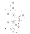
提案された方法の実施のための発電プラントは、慣用のCCPPと、煙道ガス再循環のための機器を有している。 The power plant for the implementation of the proposed method has a conventional CCPP and equipment for flue gas recirculation.
煙道ガス再循環を備えた典型的な配列が図1に示されている。第1の発電機25を駆動するガスタービン6には、圧縮機入口ガス3と、燃料5とが供給される。圧縮機入口ガス3は、周囲空気2と、煙道ガス再循環ラインを介して再循環させられた煙道ガスとの混合物である。圧縮機入口ガス3は圧縮機1において圧縮される。圧縮されたガスは燃焼器4において燃料5の燃焼のために使用され、加圧された高温ガスはタービン7において膨張する。その主な出力は電力と、高温の煙道ガス8とである。燃料は、燃料分配システム40によって燃焼器へ供給される。幾つかの場合には、典型的な実施の形態において気体燃料の噴射が言及される。しかしながら、燃料出口開口を介して燃焼空気流に液体燃料を導入することもできることが自明である。
A typical arrangement with flue gas recirculation is shown in FIG. The gas turbine 6 that drives the
ガスタービンの高温煙道ガス8はHRSG9を通過し、HRSGは、蒸気タービン13のための生蒸気を発生する。蒸気タービン13は、ガスタービン6及び第1の発電機25とともに単一軸構成で配置されているか、又は第2の発電機26を駆動するための多軸構成で配置されている。蒸気タービン13から出た蒸気は凝縮器14へ送られ、HRSGへ戻される。蒸気サイクルは単純化されており、異なる蒸気圧力レベル、給水ポンプ等を省略して概略的に示されている。なぜならば、これらは本発明の主体ではないからである。
The gas turbine
HRSGからの煙道ガス19の第1の部分流21は、ガスタービン6の圧縮機1の入口へ再循環させられ、この入口において、第1の部分流21は周囲空気2と混合される。第1の部分流21は、周囲空気2と混合される前に再循環煙道ガス冷却器27において冷却される。
A first
HRSGからの煙道ガス19の第2の部分流20は、ダンパ29によって煙突32へ送られる。煙道ガス流を高めるために、及び再循環率を制御するために、煙突32への変速煙道ガスブロワ10が、ダンパ29と煙突32との間に装備されている。さらに、再循環のための変速煙道ガスブロワ11が、煙道ガスの再循環された第1の部分流21を周囲空気2と混合する前に、再循環煙道ガス冷却器27の下流に装備されている。
A second
図2は、順次燃焼ガスタービンと、煙道ガス再循環と、変速ブロワとを備えたCCPPを概略的に示している。1つのタービン7を備えた単一燃焼器4の代わりに、順次燃焼ガスタービンは、燃焼器4を有しており、この燃焼器4の後に高圧タービン33が続いている。高圧タービン33から出た部分的に膨張させられたガスは、第2の燃焼器34において再熱された後、低圧タービン35においてさらに膨張させられる。
FIG. 2 schematically shows a CCPP with a sequential combustion gas turbine, flue gas recirculation, and a variable speed blower. Instead of a
後燃焼捕捉及び煙道ガス再循環を備えた典型的な配列が、図3に示されている。図1に示されたCCPPに加え、図3のプラントはCO2捕捉システムを有している。ガスタービンの高温の煙道ガス8はHRSG9を通過し、このHRSG9は蒸気タービン13のための生蒸気30を発生する。蒸気タービン13は、ガスタービン6及び第1の発電機25を備えた単一軸構成で配置されているか、又は第2の発電機26を駆動するための多軸構成で配置されている。さらに、蒸気は、蒸気タービン13から抽出され、蒸気ライン15を介してCO2捕捉システム18へ供給される。蒸気は、低下させられた温度で蒸気サイクルへ戻されるか、又は凝縮物として戻しライン17を介して蒸気サイクルへ再導入される。蒸気サイクルは単純化されており、異なる蒸気圧力レベル、給水ポンプ等を省略して概略的に示されている。なぜならば、これらは発明の主体でないからである。
A typical arrangement with post-combustion capture and flue gas recirculation is shown in FIG. In addition to the CCPP shown in FIG. 1, the plant of FIG. 3 has a CO 2 capture system. The gas turbine
HRSG19からの煙道ガスの第1の部分流21は、ガスタービン6の圧縮機1の入口へ再循環され、この入口において、第1の部分流21は周囲空気2と混合される。第1の部分流21は、周囲空気2と混合される前に、再循環煙道ガス冷却器27において冷却される。
A first
HRSG19からの煙道ガスの第2の部分流20は、ダンパ29によってCO2捕捉システム18へ送られる。CO2捕捉システム18の上流の煙道ガス冷却器23はこの第2の部分流20を冷却する。煙道ガス流を高めるために、及び再循環率を制御するために、CO2捕捉システム10への変速煙道ガスブロワが、煙道ガス冷却器23とCO2捕捉システム18との間に装備されている。再循環11のための変速煙道ガスブロワは、煙道ガスの再循環された第1の部分流21を周囲空気2と混合する前に、再循環煙道ガス冷却器27の下流に装備されている。
A second
CO2が除去された煙道ガス22は、CO2捕捉システム18から煙突32を介して環境へ放出される。CO2捕捉システム18が作動していない場合、煙道ガスは、煙道ガスバイパス24を介して迂回させることができる。
CO 2 flue gas 22 that is removed is released from the CO 2 capture system 18 through the
通常運転中、捕捉されたCO2はCO2圧縮機において圧縮され、圧縮されたCO2は貯蔵又はさらなる処理のために移送される。 During normal operation, the captured CO 2 is compressed in CO 2 compressors, compressed CO 2 is transferred for storage or further processing.
異なるガス流の酸素濃度をより制御しやすくするために、酸素及び/又はCO2濃度を測定するための測定装置が提案される。 In order to make it easier to control the oxygen concentration of the different gas streams, a measuring device for measuring the oxygen and / or CO 2 concentration is proposed.
再循環質量流量を制御し、再循環煙道ガス再冷却器27の後の温度を制御し、周囲空気の温度と、圧縮機1の入口質量流量とを考慮することによって、圧縮機1の入口温度を制御することができる。
Controlling recirculation mass flow rate, to control the temperature after recirculation
ベース負荷において、再冷却温度は、通常、再循環煙道ガス再冷却器27の能力によって制限され、利用可能なヒートシンクに依存する。河川又は海からの冷却水を用いる冷却水冷却器の場合、水温が、可能な再冷却温度を支配する。空気冷却器の場合、最低再冷却温度は、通常、周囲温度より5〜10℃高い温度である。再循環率に応じて、圧縮機入口温度の温度上昇は、より小さくなる。
In base load, re-cooling temperature is usually limited by the ability of the recirculating
特定の部分負荷電力出力がCCPPから要求される場合、タービン入口温度又は高温ガス温度が低下させられ、可変入口案内羽根が、運転コンセプトに従って、目標電力が達成されるまで閉鎖される。両者は、相対的な負荷低減に比例した、プラント効率の低減につながる。圧縮機入口温度を制御することによって、プラントのベース負荷電力を制御することができる。特に、圧縮機入口温度の上昇は、ベース負荷電力の減少につながる。その結果、上記の特定の電力出力は、ベース負荷において又は増大した相対電力において達せられる。増大した相対負荷での運転による効率増加が、増大した入口温度での運転による効率損失よりも大きい限り、圧縮機入口温度を高めることは、全体効率を高めることができる。プラント特定最適圧縮機入口温度を、全ての負荷設定点のために決定することができる。最適圧縮機入口温度と、周囲空気2の温度と、負荷特定ガスタービン再循環率rGTとに基づき、最適な再冷却温度Trecoolを決定することができる。ベース負荷において、再冷却温度は、再冷却器の冷却能力によって制限される。より低い負荷では、再冷却温度Trecoolを、周囲空気と再冷却された煙道ガスとの混合物が許容可能な最大圧縮機入口温度に達するまで、高めることができる。この例では、最大許容圧縮機入口温度は、固定値である。しかしながら、ガスタービン再循環率は負荷に応じて変化するので、一定の混合温度を得るために必要とされる再冷却温度Trecoolも負荷に応じて変化する。 If a specific partial load power output is required from the CCPP, the turbine inlet temperature or hot gas temperature is lowered and the variable inlet guide vanes are closed until the target power is achieved according to the operating concept. Both lead to a reduction in plant efficiency proportional to the relative load reduction. By controlling the compressor inlet temperature, the base load power of the plant can be controlled. In particular, an increase in compressor inlet temperature leads to a decrease in base load power. As a result, the specific power output described above is achieved at base load or at increased relative power. As long as the increase in efficiency due to operation at increased relative load is greater than the efficiency loss due to operation at increased inlet temperature, increasing the compressor inlet temperature can increase overall efficiency. A plant specific optimum compressor inlet temperature can be determined for all load set points. Based on the optimum compressor inlet temperature, the ambient air 2 temperature, and the load specific gas turbine recirculation rate r GT , the optimum recooling temperature T recool can be determined. In base load, re-cooling temperature is limited by the cooling capacity of the recooler. At lower loads, the recooling temperature T recool can be increased until the mixture of ambient air and recooled flue gas reaches the maximum allowable compressor inlet temperature. In this example, the maximum allowable compressor inlet temperature is a fixed value. However, since the gas turbine recirculation rate changes according to the load, the recooling temperature T recool required to obtain a constant mixing temperature also changes according to the load.
ガスタービン6の設計に応じて、許容可能な最大圧縮機入口温度は一定ではない。これは、例えば、圧縮機端部温度又は中間圧縮機からの冷却空気ブリード温度が制限的要因である場合である。その結果、再冷却温度Trecoolのための異なる制限機能が得られる。 Depending on the design of the gas turbine 6, the maximum allowable compressor inlet temperature is not constant. This is the case, for example, when the compressor end temperature or the cooling air bleed temperature from the intermediate compressor is the limiting factor. As a result, different limiting functions for the recooling temperature T recool are obtained.
より精巧な実施の形態において、周囲圧力、湿度及び入口/出口の圧力降下の影響も、例えば、負荷特定最適圧縮機入口温度及び対応する最適再冷却温度を決定するために考慮することができる。 In more sophisticated embodiments, the effects of ambient pressure, humidity and inlet / outlet pressure drop can also be considered, for example, to determine the load specific optimum compressor inlet temperature and the corresponding optimum recooling temperature.
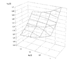
図4は、煙道ガス再循環率の例を、圧縮機出口圧力と高温ガス温度とに関連して概略的に示している。圧縮機出口圧力pk2は、設計条件下の全負荷における圧縮機出口圧力で標準化されており、高温ガス温度Thotは、設計条件下の全負荷における高温ガス温度で標準化されており、煙道ガス再循環率rFRGは、設計条件下の全負荷における煙道ガス再循環率で標準化されている。全負荷において、標準化された圧縮機出口圧力pk2と、高温ガス温度Tk2と、煙道ガス再循環率rFRGとは、1に等しい。煙道ガス再循環率rFRGは、より低い圧縮機出口圧力pk2及びより低い高温ガス温度Thotの場合には低下させられる。 FIG. 4 schematically shows an example of flue gas recirculation rate in relation to compressor outlet pressure and hot gas temperature. The compressor outlet pressure p k2 is standardized at the compressor outlet pressure at full load under design conditions, and the hot gas temperature T hot is standardized at the hot gas temperature at full load under design conditions, and the flue The gas recirculation rate r FRG is standardized by the flue gas recirculation rate at full load under design conditions. At full load, the standardized compressor outlet pressure p k2 , the hot gas temperature T k2 and the flue gas recirculation rate r FRG are equal to one. The flue gas recirculation rate r FRG is lowered for lower compressor outlet pressures p k2 and lower hot gas temperatures T hot .
順次燃焼を備えるガスタービン6の場合、煙道ガス再循環率は、第1の燃焼器4と第2の燃焼器34との高温ガス温度の関数である。これは、ここには示されていない曲線の構成につながる。通常、第1の燃焼器の高温ガス温度Thotは、50%の相対負荷、例えば全負荷に関する運転負荷、までの広い負荷範囲に亘ってほぼ一定に保たれる。従って、この曲線の配列は、単純化することができ、煙道ガス再循環率rFRGを決定するために第2の燃焼器の高温ガス温度Thotを使用することができる。
In the case of a gas turbine 6 with sequential combustion, the flue gas recirculation rate is a function of the hot gas temperature of the
高温ガス温度は通常、タービンに進入する高温ガスの平均高温ガス温度として規定される。高温ガス温度の代わりに、タービンの冷却空気との高温ガスの理論的混合温度である、いわゆるTITタービン入口温度を使用することもできる。 The hot gas temperature is usually defined as the average hot gas temperature of the hot gas entering the turbine. Instead of the hot gas temperature, the so-called TIT turbine inlet temperature, which is the theoretical mixing temperature of the hot gas with the cooling air of the turbine, can also be used.
図5は、目標煙道ガス再循環率rTの例を、圧縮機出口圧力pK2に関連して、与えられた高温ガス温度Thotのための煙道ガス再循環率調節のための許容可能な範囲とともに、概略的に示している。圧縮機出口圧力pk2は、設計条件下での全負荷における圧縮機出口圧力で標準化されている。煙道ガス再循環率rFRGと、目標煙道ガス再循環率rTと、最小煙道ガス再循環率rminと、最大煙道ガス再循環率rmaxとは、設計条件下での全負荷における煙道ガス再循環率rFRGで標準化されている。この例において、目標煙道ガス再循環率は、圧縮機出口圧力pk2に関連して、開ループ制御において決定される。実際の煙道ガス再循環率rFRGは、個々の圧縮機出口圧力pk2に対して与えられた最大煙道ガス再循環範囲rminと最大煙道ガス再循環範囲rmaxとの間の許容可能範囲内で、閉ループ制御を用いて調節される。 FIG. 5 shows an example of the target flue gas recirculation rate r T in relation to the compressor outlet pressure p K2 and the tolerance for flue gas recirculation rate adjustment for a given hot gas temperature T hot It is shown schematically with possible ranges. The compressor outlet pressure p k2 is standardized with the compressor outlet pressure at full load under design conditions. The flue gas recirculation rate r FRG , the target flue gas recirculation rate r T , the minimum flue gas recirculation rate r min and the maximum flue gas recirculation rate r max Standardized at the flue gas recirculation rate r FRG at load. In this example, the target flue gas recirculation rate is determined in open loop control in relation to the compressor outlet pressure p k2 . The actual flue gas recirculation rate r FRG is the tolerance between the maximum flue gas recirculation range r min and the maximum flue gas recirculation range r max given for the individual compressor outlet pressure p k2 To the extent possible, it is adjusted using closed loop control.
煙道ガス再循環率rFRGの閉ループ調節のために、例えば煙道ガスにおけるCO含有量又は燃焼器脈動が使用される。 For closed-loop adjustment of the flue gas recirculation rate r FRG , for example, the CO content in the flue gas or the combustor pulsation is used.
図5に示された関数は、1つの高温ガス温度Thotのために有効である。運転条件とガスタービンの設計とに応じて、高温ガス温度の影響を無視することができ、この単なる圧縮機出口圧力pk2の関数は、高温ガス温度Thotを考慮することなく全ての運転条件の場合に再循環率rFRGを制御するために使用することができる。 The function shown in FIG. 5 is valid for one hot gas temperature T hot . Depending on the operating conditions and the design of the gas turbine, the influence of the hot gas temperature can be neglected, and this simple function of the compressor outlet pressure p k2 is not affected by the hot gas temperature T hot. Can be used to control the recirculation rate r FRG .
図6は、目標煙道ガス再循環率rTの例を、与えられた圧縮機出口圧力pk2の場合の高温ガス温度Thotの関数と、煙道ガス再循環率調節のための許容可能範囲とに関連して概略的に示している。 FIG. 6 shows an example of the target flue gas recirculation rate r T as a function of the hot gas temperature T hot for a given compressor outlet pressure p k2 and the allowable for flue gas recirculation rate adjustment. It is schematically shown in relation to the range.
高温ガス温度Thotは、設計条件下での全負荷における高温ガス温度Thotで標準化されている。煙道ガス再循環率rFRGと、目標煙道ガス再循環率rTと、最小煙道ガス再循環率rminと、最大煙道ガス再循環率rmaxとは、設計条件下での全負荷における煙道ガス再循環率rFRGで標準化されている。この例では、目標煙道ガス再循環率は、高温ガス温度Thotに関連して開ループ制御において決定されている。実際の煙道ガス再循環率rFRGは、個々の高温ガス温度Thotの場合に、最小煙道ガス再循環範囲rminと最大煙道ガス再循環範囲rmaxとの間の許容可能範囲内で閉ループ制御を用いて調節される。 The hot gas temperature T hot is standardized by the hot gas temperature T hot at full load under design conditions. The flue gas recirculation rate r FRG , the target flue gas recirculation rate r T , the minimum flue gas recirculation rate r min and the maximum flue gas recirculation rate r max Standardized at the flue gas recirculation rate r FRG at load. In this example, the target flue gas recirculation rate is determined in open loop control in relation to the hot gas temperature T hot . The actual flue gas recirculation rate r FRG is within an acceptable range between the minimum flue gas recirculation range r min and the maximum flue gas recirculation range r max for each hot gas temperature T hot . Is adjusted using closed loop control.
煙道ガス再循環率rFRGの閉ループ調節のための入力変数として、例えば、煙道ガスのCO含有量又は燃焼器脈動が使用される。1つの実施の形態において、調節は、煙道ガスのCO含有量及び/又は燃焼器脈動の、目標値の逸脱に比例する。 As an input variable for the closed-loop adjustment of the flue gas recirculation rate r FRG , for example, the flue gas CO content or combustor pulsation is used. In one embodiment, the regulation is proportional to the target value deviation of the flue gas CO content and / or combustor pulsation.
運転柔軟性をさらに高め、かつ部分負荷及びベース負荷における再循環率の制限を克服するために、別の実施の形態の場合にはガスタービン入口ガスの酸素富化が提案される。 In order to further increase operational flexibility and overcome recirculation rate limitations at partial and base loads, oxygen enrichment of the gas turbine inlet gas is proposed in another embodiment.
幾つかの燃焼システムにおいては、燃焼の火炎安定性及び脈動挙動を改良するために、半径方向でのバーナの多段化が使用される。多段化は通常、局所的な高温ガス温度を増大させ、より高いNOxを生じるので、制限される。しかしながら、提案された運転方法では、煙道ガス再循環がNOx排出量を低減するので、異なる運転範囲における多段化を許容する。この増大した運転範囲を利用するために、多段化比率が燃焼圧力及び/又は煙道ガス再循環率の関数であるような方法が提案される。多段化比率は、例えば、増大した燃料流量を備えたバーナ又はバーナのグループへの最大燃料流量を、バーナごとの平均燃料流量によって割ったものとして規定される。図5に示された、圧縮機出口圧力pk2に関連した煙道ガス再循環比と同様に、圧縮機出口圧力pk2に関連したバーナ多段化の制御が提案される。 In some combustion systems, multiple stages of radial burners are used to improve the flame stability and pulsation behavior of the combustion. Multi-stage is usually limited because it increases the local hot gas temperature and produces higher NOx. However, in the proposed operating method, flue gas recirculation reduces NOx emissions, thus allowing multi-stages in different operating ranges. In order to take advantage of this increased operating range, a method is proposed in which the multistage ratio is a function of the combustion pressure and / or the flue gas recirculation rate. The multi-stage ratio is defined, for example, as the maximum fuel flow to a burner or group of burners with increased fuel flow divided by the average fuel flow per burner. Similar to the flue gas recirculation ratio associated with the compressor outlet pressure p k2 shown in FIG. 5, control of the burner multi-stage associated with the compressor outlet pressure p k2 is proposed.
燃焼の火炎安定性及び脈動挙動を改良するための別の手段として、拡散火炎を用いるパイロット化が知られている。パイロット化は、通常、局所的な高温ガス温度をも上昇させ、より多くのNOxを生じるので、制限される。しかしながら、提案された運転方法では、煙道ガス再循環がNOx排出量を低減するので、異なる運転範囲におけるパイロット化を許容する。この増大した運転範囲を利用するために、パイロット燃料流が燃焼圧力及び/又は煙道ガス再循環の関数であるような方法が提案される。図5に圧縮機出口圧力pk2に関連して示された煙道ガス再循環比率と同様に、圧縮機出口圧力pk2に関連したパイロット燃料流の制御が提案される。 Piloting with diffusion flames is known as another means to improve the flame stability and pulsation behavior of combustion. Piloting is usually limited because it also raises the local hot gas temperature and produces more NOx. However, the proposed method of operation allows piloting in different operating ranges because flue gas recirculation reduces NOx emissions. In order to take advantage of this increased operating range, a method is proposed in which the pilot fuel flow is a function of combustion pressure and / or flue gas recirculation. As with flue gas recirculation ratio which is shown in connection with the compressor outlet pressure p k2 in FIG. 5, the control of the pilot fuel flow associated with the compressor outlet pressure p k2 is proposed.
上記及び図面に記載された典型的な実施の形態は、当業者に、典型的な実施の形態とは異なりかつ発明の範囲に含まれる実施の形態を開示する。例えば、煙道ガス5の代わりに、液体燃料がガスタービンにおいて燃焼させられてもよい。 The exemplary embodiments described above and in the drawings disclose those skilled in the art to embodiments that differ from the exemplary embodiments and are within the scope of the invention. For example, instead of the flue gas 5, liquid fuel may be burned in a gas turbine.
制御パラメータとしてCO又は未燃炭化水素排出量を用いる制御方法を実現するために、ガスタービン6の下流にCO又は未燃炭化水素排出量測定装置が装着されなければならない。CO又は未燃炭化水素排出量測定装置は、例えば、ガスタービン煙道ガスCO2及び/又はO2測定装置37の位置、又はHRSG煙道ガスCO2及び/又はO2測定装置に対応する測定装置38の位置に、装着することができる。CO又は未燃炭化水素排出量測定装置は、組み合わされた測定装置であってもよい。
In order to realize a control method using CO or unburned hydrocarbon emissions as control parameters, a CO or unburned hydrocarbon emissions measuring device must be installed downstream of the gas turbine 6. The CO or unburned hydrocarbon emission measuring device is, for example, a measurement corresponding to the position of the gas turbine flue gas CO 2 and / or O 2 measuring device 37 or the HRSG flue gas CO 2 and / or O 2 measuring device. The
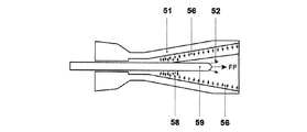
本発明の方法によって運転することができるバーナの例が、図7及び図8に示されている。示されたバーナは、円錐形の旋回ボディ51を有しており、この旋回ボディの外側シェルには、空気入口スロットの流入エッジにおいて、予混合ガスのための出口開口56,58が配置されている。
Examples of burners that can be operated by the method of the present invention are shown in FIGS. The illustrated burner has a
図7は、第1の燃料供給導管55と第2の燃料供給導管57とを備えた配列を示している。第2の予混合燃料量F2のための第2の供給導管57は、従来技術から当業者に知られているように、この旋回ボディ51の外側シェルに、空気入口スロットの流入エッジにおいて、第1の予混合燃料量F1のための第1の供給導管55に隣接して配置されている。予混合燃料は、互いに独立してこれらの2つの供給導管へ進入させられることができ、すなわち、第2の供給導管57を流過する第2の予混合燃料量F2の質量流量は、例えば、第1の供給導管55を通る第1の予混合燃料量F1の質量流量から独立して設定することができる。異なる供給導管における矢印は、第1及び第2の予混合燃料量F1,F2を示している。複数のこれらの供給対55,56が、好適にはバーナ長手方向軸線を中心にして対称に配置されていることは自明である。導管55,57から、燃料は、第1のグループにおけるn1出口開口と、第2のグループにおけるn2出口開口とを介してバーナ内に噴射される。
FIG. 7 shows an arrangement with a first
本発明の方法によって作動させることができるバーナの第2の例が図8に示されている。示されたバーナは、円錐形の旋回ボディ51を有しており、この旋回ボディ51の外側シェルには、空気入口スロットの流入エッジにおいて、予混合ガスのための出口開口56の第1のグループが配置されている。バーナにはさらに中央燃料ランス59が装着されており、この中央燃料ランスは、燃焼チャンバ端部において、すなわち、この例におけるように先端部において、ノズルを有することができ、このノズルは、液体燃料のために又はパイロット燃料FPのために使用することができる。包囲空気52のための出口開口を公知の形式でこのノズルの周囲に設けることができる。出口開口56の第1のグループへの燃料供給導管と、燃料ランス59の先端部における、液体燃料を噴射するための又はパイロット燃料FPのための燃料供給導管とに加えて、示されたバーナは、燃料ランス59における出口開口58の第2のグループへの別の燃料供給導管を有している。第2のグループの出口開口58は、実質的に、バーナ長手方向軸線方向で燃料ランス59の外面に配置されており、好適には、燃料ランス59の長手方向軸線を中心にして半径方向に対称に分配されている。これらの出口開口は、燃料が半径方向外方に向けられるように燃料ランス59から旋回空間内への燃料の噴射を可能にする。これらの出口開口58の数及び寸法、並びに軸線方向及び周方向での燃料ランス59における出口開口の分配は、消失限界、脈動、及びフラッシュバック限界等の、バーナの個々の要求に関連して選択される。
A second example of a burner that can be operated by the method of the present invention is shown in FIG. The burner shown has a
燃料ランス59は、旋回空間内へ比較的深く延びていることができるか、又は旋回空間内へ短距離だけ突出していることもできる。両方の場合において、出口開口58の第2のグループは、好適には、図示されているように、燃料ランス59に、旋回空間の後方領域において、すなわち燃焼器から最も離れた領域において配置されている。
The
この実施の形態において、燃料ランスとは、パイロットステージとして、又は予混合された燃料の発生のための噴射箇所として働く。 In this embodiment, the fuel lance serves as a pilot stage or as an injection point for the generation of premixed fuel.
これらの典型的な実施の形態においても、出口開口58の第2のグループへの燃料供給から独立して、出口開口56の第1のグループへの燃料供給の開鎖(open chain)又は閉ループ制御を有することも明らかに可能である。図7及び図8の実施の形態は、バーナの極めて有利な多段運転モードを可能にし、このモードにおいては、出口開口56の第1のグループへの燃料供給導管と、出口開口58の第2のグループへの燃料供給導管とに、予混合ガスが供給される。出口開口56,58の第1及び第2のグループへの燃料供給を独立して制御することができることは、バーナ又はバーナを利用する装置の個々の運転条件に最適に適合させられた運転モードを可能にする。また、燃料を出口開口56,58の第1及び第2のグループに独占的に、すなわち他方の個々のグループに供給することなく、供給することが可能である。
In these exemplary embodiments, the open chain or closed loop control of the fuel supply to the first group of
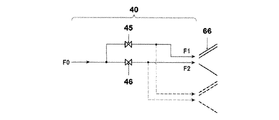
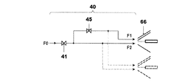
2つの供給ダクトへの燃料供給は、互いに独立して、図7及び図8には明示されていない制御弁によって設定することができる。燃料制御弁の配列は図示されていない。対応する燃料制御弁を備えた適切な燃料ガスシステム40の例は、図9から図11に示されている。
The fuel supply to the two supply ducts can be set independently of each other by means of control valves not explicitly shown in FIGS. The arrangement of the fuel control valves is not shown. Examples of suitable
図9から図11は、燃料量F0がバーナに供給される燃料分配システムの例を示している。図9及び図10の例において、全燃料量F0を、出口開口56の第1のグループのための燃料量F1と、出口開口58の第2のグループのための燃料量F2とに分割するために、燃料ラインは分岐している。
9 to 11 show examples of the fuel distribution system in which the fuel amount F0 is supplied to the burner. In the example of FIGS. 9 and 10, to divide the total
図9は、制御弁45が出口開口56の第1のグループ(図7及び図8に示されている)のための分岐路に配置されており、制御弁46が出口開口58の第2のグループのための分岐路に配置されている実施の形態を示している。
FIG. 9 shows that the
この例において、制御弁45及び46は燃料質量流量を別個に制御する。燃焼器への合計燃料質量流量は、両者の合計である。
In this example,
図10は、一方の制御弁41が、合計燃料量F0を設定するために分岐路の前に配置されており、かつ制御弁45が出口開口56の第1のグループ(図7及び図8に示されている)のための分岐路に配置されている実施の形態を示している。制御弁45を制御することによって、質量流量比をF1とF2との間で変化させることが可能である。この例において、制御弁45は、もちろん、出口開口58の第2のグループへの分岐路に配置することもできる。
FIG. 10 shows that one
図11は、付加的な制御弁47が、パイロットへの燃料流を制御するための付加的な分岐路に配置されている実施の形態を示している。この例においては、制御弁45,46,47は燃料流を別個に制御する。燃焼器への合計燃料量は、これらすべての流れの合計である。
FIG. 11 shows an embodiment in which an
全ての典型的な実施の形態において、燃料量比F1/F0、F2/F0、及びFP/F0は、発電プラントの運転条件に関連して制御弁を作動させることによって変化させられる。量の比の変化は、本明細書の前の部分において既に述べられているように開鎖(open chain)又は閉ループ形式で、異なる測定された運転値に関連して制御することができる。示された設計は、バーナジオメトリから独立している。 In all exemplary embodiments, the fuel quantity ratios F1 / F0, F2 / F0, and FP / F0 are varied by operating the control valve in relation to the operating conditions of the power plant. The change in the ratio of quantities can be controlled in relation to different measured operating values in an open chain or closed loop manner as already mentioned in the previous part of the specification. The design shown is independent of burner geometry.
さらに、このような配列により、図に点線で示されているように、複数のバーナに、設定された燃料量比で燃料が同時に供給されることができる。 Further, with such an arrangement, as shown by dotted lines in the figure, fuel can be simultaneously supplied to a plurality of burners at a set fuel amount ratio.
図12から図14は、環状燃焼器の周方向で制御された不均一性を提供するように構成された燃料分配システムを備えた環状燃焼器の典型的な断面図を示している。これらの図は、多数の個々のバーナ66を備えた環状燃焼器55の断面図を示している。
FIGS. 12-14 illustrate exemplary cross-sectional views of an annular combustor with a fuel distribution system configured to provide a circumferential non-uniformity of the annular combustor. These figures show a cross-sectional view of an
図12は、環状燃焼器55における2つのバーナグループを多段化するための燃料分配システム40の例を概略的に示している。合計燃料量F0は燃料分配システム40を介してバーナ66に供給される。燃料分配システム40は、第1のバーナグループのための燃料制御弁63と、第2のバーナグループのための燃料制御弁64と、第1のバーナグループのためのマニホールド61と、第2のバーナグループのためのマニホールド62と、個々のバーナ66への燃料供給部60とを有している。燃料量F1及びF2は、個々のマニホールド及びバーナ供給部60を介して個々のバーナグループの個々のバーナへ供給される。
FIG. 12 schematically shows an example of the
図13は、1つのバーナグループを備えた燃料分配システム40の例を概略的に示している。燃料分配システム40は、主燃料制御弁41と、マニホールド39と、個々のバーナ66への燃料供給部60とを有している。
FIG. 13 schematically shows an example of a
付加的な単一のバーナを多段化するために、個々のバーナ66への燃料量FXの制御のための制御弁65が装着されている。多段化は、個々の単一バーナ制御弁65の下流の個々のバーナに供給される燃料量FXを減じるための、単一バーナ制御弁65の制御された閉鎖によって実現される。全ての他のバーナ66には、燃料量F1がマニホールド39及び燃料供給部60を介して供給される。
In order to multistage the additional single burner, a
択一的な実施の形態において、オリフィス(図示せず)が、単一バーナ制御弁65が装着されていない、燃料供給部60の部分又は全てに装着されている。多段化は、単一バーナ制御弁65の制御された開閉によって実現される。この実施の形態において、単一バーナ制御弁65の開放は、個々の単一バーナ制御弁65の下流の個々のバーナへの燃料量FXの噴射を許容し、この燃料量FXは、マニホールド39と、オリフィスと、燃料供給部60とを介して供給される燃料量F1よりも大きい。
In an alternative embodiment, an orifice (not shown) is mounted on a portion or all of the
これに関連して、制御された開閉とは、全開と全閉との間の全ての弁位置を含む。例えば、制御された開閉は、弁の部分的な閉鎖を含む。 In this context, controlled opening and closing includes all valve positions between fully open and fully closed. For example, controlled opening and closing includes partial closing of the valve.
図14は、燃料分配システムの第3の例を概略的に示している。ここでは、燃料分配システム40は、主燃料制御弁41と、マニホールド39と、個々のバーナ66への燃料供給部60と、各バーナ66の燃料供給ライン60における単一バーナ制御弁とを有している。これは、全ての運転条件下で多段化パターンの柔軟な変更を許容する。
FIG. 14 schematically shows a third example of the fuel distribution system. Here, the
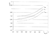
図15は、NOx排出量をあるレベルに維持するために理論的に必要とされる煙道ガス再循環率rFRGに関連した許容可能な提供された燃焼不均一性比riを概略的に示している。図15は、同じNOx排出レベルにつながる、運転曲線のための3つの例を示している。燃焼器脈動、燃焼器不安定性、CO排出量、又はその他の制限等の可能な制限は、無視されている。曲線は、煙道ガス再循環率rFRGに関連した許容可能な提供された燃焼不均一性比riの依存度を示している。高温ガス温度Thotが上昇すると、与えられた煙道ガス再循環率rFRGにおいて同じNOx排出レベルを維持するための許容可能な提供された燃焼不均一性比riは、減じられる。一点鎖線は、最も低い高温ガス温度Thotでの運転に対応する。実線は、最も高い高温ガス温度Thotでの運転に対応する。 FIG. 15 schematically illustrates an acceptable provided combustion heterogeneity ratio r i related to the flue gas recirculation rate r FRG that is theoretically required to maintain NOx emissions at a certain level. Show. FIG. 15 shows three examples for the operating curve that lead to the same NOx emission level. Possible limits such as combustor pulsation, combustor instability, CO emissions, or other limits are ignored. The curve shows the dependence of the acceptable provided combustion heterogeneity ratio r i related to the flue gas recirculation rate r FRG . As the hot gas temperature T hot increases, the acceptable provided combustion heterogeneity ratio r i to maintain the same NOx emission level at a given flue gas recirculation rate r FRG is reduced. The alternate long and short dash line corresponds to operation at the lowest hot gas temperature T hot . The solid line corresponds to the operation at the highest hot gas temperature T hot .
与えられた高温ガス温度Thotの場合、許容可能な課された燃焼不均一性比riは、煙道ガス再循環率rFRGに比例する、すなわち、より高い提供された燃焼不均一性比riは、与えられたNOx排出レベルのための煙道ガス再循環によって実現することができる。従って、合計運転範囲を、煙道ガス再循環率rFRGに関連して、課された燃焼不均一性比riを制御することによって拡大することができる。 For a given hot gas temperature T hot , the acceptable imposed combustion heterogeneity ratio r i is proportional to the flue gas recirculation rate r FRG , ie, a higher provided combustion heterogeneity ratio. r i can be achieved by flue gas recirculation for a given NOx emission level. Thus, the total operating range can be expanded by controlling the imposed combustion heterogeneity ratio r i in relation to the flue gas recirculation rate r FRG .
図16は、一定のNOx排出量での理論的運転のための高温ガス温度Thotの例を、煙道ガス再循環率rFRGと、課された燃焼不均一性比riとに関連して、概略的に示している。燃焼器脈動、燃焼不安定性、CO排出量、又はその他の制限等の可能な制限は、全体的な機能において無視されている。与えられたNOx排出レベルのための高温ガス温度Thotは、煙道ガス再循環率rFRGに比例し、課された燃焼不均一性比riに反比例する。煙道ガス再循環率rFRGと課された燃焼不均一性比riとに関連した一定のNOx排出量を備えた理論的運転のための高温ガス温度Thotの機能に加え、脈動限界PLが示されている。課された燃焼不均一性比riの増大は、より高い火炎安定性につながり、これは、より高い煙道ガス再循環率rFRGを許容し、最終的に、より高い高温ガス温度Thotにおける安定した運転につながる。より高い高温ガス温度Thotの結果、同じNOx排出レベルを維持しつつ、プラントの性能、すなわちプラントの電力及び効率を高めることができる。択一的に、性能の不利なしにNOx排出量を減じることができる。 FIG. 16 shows an example of the hot gas temperature T hot for theoretical operation with constant NOx emissions, related to the flue gas recirculation rate r FRG and the imposed combustion heterogeneity ratio r i. It is shown schematically. Possible limits such as combustor pulsation, combustion instability, CO emissions, or other limits are ignored in the overall function. The hot gas temperature T hot for a given NOx emission level is proportional to the flue gas recirculation rate r FRG and inversely proportional to the imposed combustion heterogeneity ratio r i . In addition to the function of hot gas temperature T hot for theoretical operation with constant NOx emissions related to flue gas recirculation rate r FRG and imposed combustion heterogeneity ratio r i , pulsation limit PL It is shown. Increasing the imposed combustion heterogeneity ratio r i leads to higher flame stability, which allows a higher flue gas recirculation rate r FRG and ultimately higher hot gas temperature T hot. Leads to stable operation. As a result of the higher hot gas temperature T hot , plant performance, ie, plant power and efficiency, can be increased while maintaining the same NOx emission level. Alternatively, NOx emissions can be reduced without performance penalty.
図15及び図16において、標準化された量が使用されている。高温ガス温度Thotは、設計条件下の全負荷での高温ガス温度で標準化されており、煙道ガス再循環率rFRGは、設計条件下の全負荷での煙道ガス再循環率で標準化されている。全負荷において、標準化された高温ガス温度Thotと、煙道ガス再循環率rFRGとは、1に等しい。課された燃焼不均一性比riは、対応するハードウェア、すなわちバーナグループ分け、多段化又はパイロット化によって設計条件において実現することができる最大不均一性で標準化されている。 In FIG. 15 and FIG. 16, standardized quantities are used. The hot gas temperature T hot is standardized at the hot gas temperature at full load under the design conditions, and the flue gas recirculation rate r FRG is standardized at the flue gas recirculation rate at full load under the design conditions. Has been. At full load, the standardized hot gas temperature T hot and the flue gas recirculation rate r FRG are equal to one. The imposed combustion non-uniformity ratio r i is standardized with the maximum non-uniformity that can be achieved in the design conditions by corresponding hardware, ie burner grouping, multistage or piloting.
1 圧縮機
2 周囲空気
3 圧縮機入口ガス
4 燃焼器
5 GTのための煙道ガス
6 ガスタービンGT
7 タービン
8 ガスタービンからの高温煙道ガス
9 HRSG(熱回収蒸気発生器)
10 (CO2捕捉システムへの)第2の部分流のための煙道ガスブロワ
11 第1の部分流のための煙道ガスブロワ(煙道ガス再循環)
12 バイパスフラップ又は弁
13 蒸気タービン
14 凝縮器
15 CO2捕捉のための蒸気抽出部
16 給水部
17 凝縮物戻しライン
18 CO2捕捉システム
19 HRSGからの煙道ガス
20 第2の部分流(CO2捕捉システムへの煙道ガスライン)
21 第1の部分流(煙道ガス再循環)
22 CO2除去された煙道ガス
23 (第2の部分流のための)煙道ガス冷却器
24 煙突への煙道ガスバイパス
25 第1の発電機
26 第2の発電機
27 (第1の部分流のための)再循環煙道ガス再冷却器
28 圧縮機出口圧力又は出口温度測定装置
29 煙道ガス分割装置
30 生蒸気
31 捕捉されたCO2
32 煙突
33 高圧タービン
34 第2の燃焼器
35 低圧タービン
36 入口空気CO2及び/又はO2測定装置
37 ガスタービン煙道ガスCO2及び/又はO2測定装置
38 HRSG煙道ガスCO2及び/又はO2測定装置
39 マニホールド
40 燃料分配システム
41 主燃料制御弁
45,46,47 制御弁
51 旋回ボディ
52 包囲空気
53 バーナ長手方向軸線
55 第1の供給導管
56 出口開口の第1のグループ
57 第2の供給導管
58 出口開口の第2のグループ
59 燃料ランス
60 燃料供給部
61 第1のバーナグループのためのマニホールド
62 第2のバーナグループのためのマニホールド
63 第1のバーナグループのための燃料制御弁
64 第2のバーナグループのための燃料制御弁
65 単一バーナ制御弁
66 バーナ
CCPP コンバインドサイクル発電プラント
F0 合計燃料量
F1,F2 燃料量
FP パイロット燃料量
n1 第1のグループにおける出口開口の数
n2 第2のグループにおける出口開口の数
pk2 圧縮機出口圧力
rFRG 煙道ガス再循環率
ri 課された燃焼不均一性比
rT 目標再循環率
rmin 最小再循環率
rmax 最大再循環率
Thot 高温ガス温度
DESCRIPTION OF
7
10 Flue gas blower for second partial flow (to CO 2 capture system) 11 Flue gas blower for first partial flow (flue gas recirculation)
12 Bypass flap or
21 First partial flow (flue gas recirculation)
22 CO 2 removal flue gas 23 (the second order partial flow)
32
Claims (15)
Applications Claiming Priority (4)
| Application Number | Priority Date | Filing Date | Title |
|---|---|---|---|
| CH00841/10A CH703218A1 (en) | 2010-05-26 | 2010-05-26 | Method of operating a combined cycle with flue gas recirculation and power plant. |
| CH00841/10 | 2010-05-26 | ||
| CH01925/10 | 2010-11-17 | ||
| CH01925/10A CH704118A1 (en) | 2010-11-17 | 2010-11-17 | Method for operating combined cycle power plant, involves controlling combustion in-homogeneity ratio as function of flue gas recirculation rate of gases, and re-circulating flue gases into compressor inlet air of gas turbine |
Publications (3)
| Publication Number | Publication Date |
|---|---|
| JP2011247265A JP2011247265A (en) | 2011-12-08 |
| JP2011247265A5 JP2011247265A5 (en) | 2015-05-14 |
| JP5836645B2 true JP5836645B2 (en) | 2015-12-24 |
Family
ID=44924931
Family Applications (1)
| Application Number | Title | Priority Date | Filing Date |
|---|---|---|---|
| JP2011117927A Expired - Fee Related JP5836645B2 (en) | 2010-05-26 | 2011-05-26 | Combined cycle power plant with flue gas recirculation |
Country Status (3)
| Country | Link |
|---|---|
| US (1) | US9828912B2 (en) |
| JP (1) | JP5836645B2 (en) |
| DE (1) | DE102011102720B4 (en) |
Families Citing this family (44)
| Publication number | Priority date | Publication date | Assignee | Title |
|---|---|---|---|---|
| CH703218A1 (en) | 2010-05-26 | 2011-11-30 | Alstom Technology Ltd | Method of operating a combined cycle with flue gas recirculation and power plant. |
| US9903316B2 (en) * | 2010-07-02 | 2018-02-27 | Exxonmobil Upstream Research Company | Stoichiometric combustion of enriched air with exhaust gas recirculation |
| SG186156A1 (en) * | 2010-07-02 | 2013-01-30 | Exxonmobil Upstream Res Co | Stoichiometric combustion with exhaust gas recirculation and direct contact cooler |
| SG186158A1 (en) * | 2010-07-02 | 2013-01-30 | Exxonmobil Upstream Res Co | Low emission power generation systems and methods |
| EP2568127B1 (en) * | 2011-09-07 | 2015-02-25 | Alstom Technology Ltd | Method for operating a power plant |
| EP2578839A1 (en) * | 2011-10-06 | 2013-04-10 | Alstom Technology Ltd | Method for the operation of a gas turbine with flue gas recirculation and corresponding apparatus |
| EP2795084B1 (en) * | 2011-12-19 | 2020-02-05 | Ansaldo Energia IP UK Limited | Control of the gas composition in a gas turbine power plant with flue gas recirculation |
| CH706150A1 (en) * | 2012-02-29 | 2013-08-30 | Alstom Technology Ltd | Process for enterprises of a gas turbine power plant with flue gas recirculation and gas turbine engine. |
| ITCO20120008A1 (en) | 2012-03-01 | 2013-09-02 | Nuovo Pignone Srl | METHOD AND SYSTEM FOR MONITORING THE CONDITION OF A GROUP OF PLANTS |
| EP2642097A1 (en) | 2012-03-21 | 2013-09-25 | Alstom Technology Ltd | Method for operating a gas turbine and gas turbine for carrying out the method |
| EP2642098A1 (en) * | 2012-03-24 | 2013-09-25 | Alstom Technology Ltd | Gas turbine power plant with non-homogeneous input gas |
| US20130255267A1 (en) * | 2012-03-30 | 2013-10-03 | General Electric Company | System and method of improving emission performance of a gas turbine |
| US20130269358A1 (en) * | 2012-04-12 | 2013-10-17 | General Electric Company | Methods, systems and apparatus relating to reheat combustion turbine engines with exhaust gas recirculation |
| CN104428516B (en) * | 2012-07-13 | 2017-08-18 | 通用电器技术有限公司 | Gas turbine power device and its operation method with flue gas recirculation |
| EP2703607A1 (en) * | 2012-09-04 | 2014-03-05 | Alstom Technology Ltd | A method of increasing electricity output during high demand |
| US10215412B2 (en) * | 2012-11-02 | 2019-02-26 | General Electric Company | System and method for load control with diffusion combustion in a stoichiometric exhaust gas recirculation gas turbine system |
| US9567913B2 (en) * | 2013-01-28 | 2017-02-14 | General Electric Company | Systems and methods to extend gas turbine hot gas path parts with supercharged air flow bypass |
| EP2829705A1 (en) * | 2013-07-24 | 2015-01-28 | Alstom Technology Ltd | Gas turbine and method of controlling gas turbine |
| US9903588B2 (en) * | 2013-07-30 | 2018-02-27 | General Electric Company | System and method for barrier in passage of combustor of gas turbine engine with exhaust gas recirculation |
| EP2835516A1 (en) * | 2013-08-08 | 2015-02-11 | Alstom Technology Ltd | Gas turbine with improved part load emissions behavior |
| EP2837778A1 (en) | 2013-08-15 | 2015-02-18 | ALSTOM Technology Ltd | Operation of a gas turbine power plant with carbon dioxide separation |
| EP2853719A1 (en) * | 2013-09-25 | 2015-04-01 | Alstom Technology Ltd | Gas turbine with staged fuel injection |
| EP2894405B1 (en) * | 2014-01-10 | 2016-11-23 | General Electric Technology GmbH | Sequential combustion arrangement with dilution gas |
| US9492780B2 (en) | 2014-01-16 | 2016-11-15 | Bha Altair, Llc | Gas turbine inlet gas phase contaminant removal |
| US10060359B2 (en) * | 2014-06-30 | 2018-08-28 | General Electric Company | Method and system for combustion control for gas turbine system with exhaust gas recirculation |
| US10502136B2 (en) | 2014-10-06 | 2019-12-10 | Bha Altair, Llc | Filtration system for use in a gas turbine engine assembly and method of assembling thereof |
| US10253690B2 (en) * | 2015-02-04 | 2019-04-09 | General Electric Company | Turbine system with exhaust gas recirculation, separation and extraction |
| US10316746B2 (en) * | 2015-02-04 | 2019-06-11 | General Electric Company | Turbine system with exhaust gas recirculation, separation and extraction |
| AU2017223264B2 (en) * | 2016-02-26 | 2019-08-29 | 8 Rivers Capital, Llc | Systems and methods for controlling a power plant |
| DE102016218347A1 (en) | 2016-09-23 | 2018-03-29 | Siemens Aktiengesellschaft | Power plant |
| EP3620620A1 (en) * | 2018-09-07 | 2020-03-11 | Siemens Aktiengesellschaft | Exhaust gas recirculation in gas and steam turbines plants |
| US11156164B2 (en) | 2019-05-21 | 2021-10-26 | General Electric Company | System and method for high frequency accoustic dampers with caps |
| US11174792B2 (en) | 2019-05-21 | 2021-11-16 | General Electric Company | System and method for high frequency acoustic dampers with baffles |
| EP3822469B1 (en) * | 2019-11-18 | 2023-01-04 | Ansaldo Energia Switzerland AG | Gas turbine engine with alternating patterns of active burners and method of controlling a gas turbine engine |
| WO2022094605A1 (en) * | 2020-10-30 | 2022-05-05 | Colorado State University Research Foundation | Synergistic heat pumped thermal storage and flexible carbon capture system |
| CN112923771B (en) * | 2021-04-02 | 2022-08-30 | 山东大学 | Wet flue gas source heat pump system capable of controlling spraying according to exhaust gas temperature |
| CN113091477B (en) * | 2021-04-02 | 2022-02-22 | 山东大学 | Wet flue gas source heat pump system for controlling input flue gas pressure |
| CN112923770B (en) * | 2021-04-02 | 2022-02-22 | 山东大学 | Novel wet flue gas source heat pump system for water collection, waste heat recovery and pollutant removal |
| WO2023287926A1 (en) * | 2021-07-13 | 2023-01-19 | Pts Power Inc. | Exhaust gas path heat energy utilization system and method |
| CN113417741A (en) * | 2021-08-12 | 2021-09-21 | 华北电力大学(保定) | Improved gas-steam combined cycle unit and control method thereof |
| US11852074B1 (en) * | 2022-07-12 | 2023-12-26 | General Electric Company | Combined cycle power plants with exhaust gas recirculation intercooling |
| WO2024141148A1 (en) * | 2022-12-26 | 2024-07-04 | General Electric Technology Gmbh | Systems for stabilizing gas turbine engine output during grid events |
| WO2025133001A1 (en) * | 2023-12-22 | 2025-06-26 | Technip Energies France | Carbon capture system with a blowerless configuration |
| EP4574242A1 (en) * | 2023-12-22 | 2025-06-25 | Technip Energies France | Carbon capture system with a blowerless configuration |
Family Cites Families (46)
| Publication number | Priority date | Publication date | Assignee | Title |
|---|---|---|---|---|
| US3546882A (en) * | 1968-04-24 | 1970-12-15 | Gen Electric | Gas turbine engines |
| US3703807A (en) | 1971-01-15 | 1972-11-28 | Laval Turbine | Combined gas-steam turbine power plant |
| US3785145A (en) | 1971-11-10 | 1974-01-15 | Gen Motors Corp | Gas turbine power plant |
| DE2731387A1 (en) | 1976-07-19 | 1978-01-26 | Hydragon Corp | Exhaust gas feedback for gas turbines - has feedback rate determined by combination of air compressor intake and turbine intake temp. |
| JPS5773827A (en) | 1980-10-24 | 1982-05-08 | Hitachi Ltd | Nox reducing device |
| US4441435A (en) * | 1981-10-21 | 1984-04-10 | Hitachi, Ltd. | Fluidizing gas control system in fluidized-bed incinerator |
| US5402631A (en) | 1991-05-10 | 1995-04-04 | Praxair Technology, Inc. | Integration of combustor-turbine units and integral-gear pressure processors |
| US5235814A (en) * | 1991-08-01 | 1993-08-17 | General Electric Company | Flashback resistant fuel staged premixed combustor |
| JP2954456B2 (en) | 1993-07-14 | 1999-09-27 | 株式会社日立製作所 | Exhaust recirculation combined plant |
| US5794431A (en) | 1993-07-14 | 1998-08-18 | Hitachi, Ltd. | Exhaust recirculation type combined plant |
| DE4446610A1 (en) | 1994-12-24 | 1996-06-27 | Abb Management Ag | Process for operating a gas turbine group |
| US6256976B1 (en) | 1997-06-27 | 2001-07-10 | Hitachi, Ltd. | Exhaust gas recirculation type combined plant |
| EP0953748B1 (en) | 1998-04-28 | 2004-01-28 | ALSTOM (Switzerland) Ltd | Power plant with a CO2-cycle |
| US6260400B1 (en) | 1998-12-14 | 2001-07-17 | Gohysu Corporation | Full enclosed forging apparatus |
| JP3614751B2 (en) * | 2000-03-21 | 2005-01-26 | 東京電力株式会社 | Thermal efficiency diagnosis method and apparatus for combined power plant |
| CA2409700C (en) | 2000-05-12 | 2010-02-09 | Clean Energy Systems, Inc. | Semi-closed brayton cycle gas turbine power systems |
| AU2001272682A1 (en) | 2000-06-15 | 2001-12-24 | Alstom Power N.V. | Method for operating a burner and burner with stepped premix gas injection |
| US6430914B1 (en) * | 2000-06-29 | 2002-08-13 | Foster Wheeler Energy Corporation | Combined cycle power generation plant and method of operating such a plant |
| GB2399600B (en) | 2001-10-26 | 2005-12-14 | Alstom Technology Ltd | Gas turbine adapted to operate with a high exhaust gas recirculation rate and a method for operation thereof |
| US6962055B2 (en) * | 2002-09-27 | 2005-11-08 | United Technologies Corporation | Multi-point staging strategy for low emission and stable combustion |
| JP3702266B2 (en) * | 2002-11-13 | 2005-10-05 | 三菱重工業株式会社 | Steam turbine output estimation device in dual fuel type single shaft combined plant |
| US7191587B2 (en) | 2002-11-13 | 2007-03-20 | American Air Liquide, Inc. | Hybrid oxygen-fired power generation system |
| DK1576266T3 (en) | 2002-11-15 | 2014-12-01 | Clean Energy Systems Inc | Low pollutant energy generation system with air separation using an ion transfer membrane |
| EP1583893A1 (en) * | 2002-12-12 | 2005-10-12 | Ebara Corporation | Gas turbine apparatus |
| WO2004072453A1 (en) * | 2003-02-11 | 2004-08-26 | Alstom Technology Ltd | Method for operating a gas turbine group |
| DE112004000994T5 (en) | 2003-06-06 | 2006-06-14 | Precision Combustion, Inc., North Haven | Method of obtaining ultra-low NOx emissions from gas turbines operating at high turbine inlet temperatures |
| US7007487B2 (en) * | 2003-07-31 | 2006-03-07 | Mes International, Inc. | Recuperated gas turbine engine system and method employing catalytic combustion |
| DE10360951A1 (en) | 2003-12-23 | 2005-07-28 | Alstom Technology Ltd | Thermal power plant with sequential combustion and reduced CO2 emissions and method of operating such a plant |
| DE102004015187A1 (en) | 2004-03-29 | 2005-10-20 | Alstom Technology Ltd Baden | Combustion chamber for a gas turbine and associated operating method |
| DE102004036911A1 (en) | 2004-07-29 | 2006-03-23 | Alstom Technology Ltd | Operating procedure for a combustion plant |
| DE102004039164A1 (en) * | 2004-08-11 | 2006-03-02 | Alstom Technology Ltd | Method for generating energy in a gas turbine comprehensive power generation plant and power generation plant for performing the method |
| NO20044456L (en) | 2004-10-20 | 2005-03-03 | Norsk Hydro As | Procedure for Removal and Recovery of CO 2 from Exhaust Gas |
| DE102005015151A1 (en) | 2005-03-31 | 2006-10-26 | Alstom Technology Ltd. | Gas turbine system for power station, has control device to control volume flow and/or temperature of combustion exhaust gas, such that fresh gas-exhaust gas-mixture entering into compressor of turbo group has preset reference temperature |
| US7950217B2 (en) * | 2005-08-12 | 2011-05-31 | American Air Liquide, Inc. | Oxygen-enriched air assisting system for improving the efficiency of cogeneration system |
| WO2007087907A1 (en) | 2006-01-11 | 2007-08-09 | Alstom Technology Ltd | Method for the operation of a firing plant |
| GB2434437B (en) * | 2006-01-19 | 2011-01-26 | Siemens Ag | Improvements in or relating to combustion apparatus |
| US7805922B2 (en) * | 2006-02-09 | 2010-10-05 | Siemens Energy, Inc. | Fuel flow tuning for a stage of a gas turbine engine |
| US20080076080A1 (en) * | 2006-09-22 | 2008-03-27 | Tailai Hu | Method and apparatus for optimizing high fgr rate combustion with laser-based diagnostic technology |
| US8046986B2 (en) | 2007-12-10 | 2011-11-01 | General Electric Company | Method and system for controlling an exhaust gas recirculation system |
| US7536252B1 (en) | 2007-12-10 | 2009-05-19 | General Electric Company | Method and system for controlling a flowrate of a recirculated exhaust gas |
| US8051638B2 (en) | 2008-02-19 | 2011-11-08 | General Electric Company | Systems and methods for exhaust gas recirculation (EGR) for turbine engines |
| US9297306B2 (en) | 2008-09-11 | 2016-03-29 | General Electric Company | Exhaust gas recirculation system, turbomachine system having the exhaust gas recirculation system and exhaust gas recirculation control method |
| EP2246532A1 (en) | 2008-12-24 | 2010-11-03 | Alstom Technology Ltd | Power plant with CO2 capture |
| EP2248999A1 (en) | 2008-12-24 | 2010-11-10 | Alstom Technology Ltd | Power plant with CO2 capture |
| CH703218A1 (en) | 2010-05-26 | 2011-11-30 | Alstom Technology Ltd | Method of operating a combined cycle with flue gas recirculation and power plant. |
| US8915733B2 (en) * | 2010-11-11 | 2014-12-23 | Air Products And Chemicals, Inc. | Selective adjustment of heat flux for increased uniformity of heating a charge material in a tilt rotary furnace |
-
2011
- 2011-05-20 DE DE102011102720.7A patent/DE102011102720B4/en active Active
- 2011-05-26 US US13/116,486 patent/US9828912B2/en active Active
- 2011-05-26 JP JP2011117927A patent/JP5836645B2/en not_active Expired - Fee Related
Also Published As
| Publication number | Publication date |
|---|---|
| JP2011247265A (en) | 2011-12-08 |
| US20110289899A1 (en) | 2011-12-01 |
| DE102011102720B4 (en) | 2021-10-28 |
| DE102011102720A1 (en) | 2011-12-01 |
| US9828912B2 (en) | 2017-11-28 |
Similar Documents
| Publication | Publication Date | Title |
|---|---|---|
| JP5836645B2 (en) | Combined cycle power plant with flue gas recirculation | |
| JP5836644B2 (en) | Combined cycle power plant with flue gas recirculation | |
| US20220282668A1 (en) | System and method for load control with diffusion combustion in a stoichiometric exhaust gas recirculation gas turbine system | |
| CN102265004B (en) | Power plant with CO2 capture | |
| US10100741B2 (en) | System and method for diffusion combustion with oxidant-diluent mixing in a stoichiometric exhaust gas recirculation gas turbine system | |
| JP4735548B2 (en) | High-humidity air-utilizing gas turbine and its operating method | |
| JP2015518540A (en) | System and method for stoichiometric EGR gas turbine system | |
| US10151487B2 (en) | Sequential combustion arrangement with dilution gas | |
| JP2011153624A (en) | Method of operating gas turbine and gas turbine | |
| JP5480792B2 (en) | Gas turbine system and humidification control method for gas turbine | |
| US20130160456A1 (en) | System and method for controlling oxygen emissions from a gas turbine | |
| WO2024205604A1 (en) | System and method having oxidant supply for duct burner of heat recovery steam generator | |
| CN104421003B (en) | Gas turbine combustion system |
Legal Events
| Date | Code | Title | Description |
|---|---|---|---|
| A621 | Written request for application examination |
Free format text: JAPANESE INTERMEDIATE CODE: A621 Effective date: 20140106 |
|
| A977 | Report on retrieval |
Free format text: JAPANESE INTERMEDIATE CODE: A971007 Effective date: 20141219 |
|
| A131 | Notification of reasons for refusal |
Free format text: JAPANESE INTERMEDIATE CODE: A131 Effective date: 20150105 |
|
| A524 | Written submission of copy of amendment under section 19 (pct) |
Free format text: JAPANESE INTERMEDIATE CODE: A524 Effective date: 20150330 |
|
| TRDD | Decision of grant or rejection written | ||
| A01 | Written decision to grant a patent or to grant a registration (utility model) |
Free format text: JAPANESE INTERMEDIATE CODE: A01 Effective date: 20151005 |
|
| A61 | First payment of annual fees (during grant procedure) |
Free format text: JAPANESE INTERMEDIATE CODE: A61 Effective date: 20151104 |
|
| R150 | Certificate of patent or registration of utility model |
Ref document number: 5836645 Country of ref document: JP Free format text: JAPANESE INTERMEDIATE CODE: R150 |
|
| S533 | Written request for registration of change of name |
Free format text: JAPANESE INTERMEDIATE CODE: R313533 |
|
| R350 | Written notification of registration of transfer |
Free format text: JAPANESE INTERMEDIATE CODE: R350 |
|
| S111 | Request for change of ownership or part of ownership |
Free format text: JAPANESE INTERMEDIATE CODE: R313113 |
|
| R350 | Written notification of registration of transfer |
Free format text: JAPANESE INTERMEDIATE CODE: R350 |
|
| LAPS | Cancellation because of no payment of annual fees |