JP5836627B2 - Crawler mandrel and elastic crawler - Google Patents
Crawler mandrel and elastic crawler Download PDFInfo
- Publication number
- JP5836627B2 JP5836627B2 JP2011092370A JP2011092370A JP5836627B2 JP 5836627 B2 JP5836627 B2 JP 5836627B2 JP 2011092370 A JP2011092370 A JP 2011092370A JP 2011092370 A JP2011092370 A JP 2011092370A JP 5836627 B2 JP5836627 B2 JP 5836627B2
- Authority
- JP
- Japan
- Prior art keywords
- core metal
- width direction
- crawler
- core
- wheel
- Prior art date
- Legal status (The legal status is an assumption and is not a legal conclusion. Google has not performed a legal analysis and makes no representation as to the accuracy of the status listed.)
- Expired - Fee Related
Links
- 239000002184 metal Substances 0.000 claims description 201
- 229910052751 metal Inorganic materials 0.000 claims description 201
- 239000000758 substrate Substances 0.000 claims description 42
- 230000002093 peripheral effect Effects 0.000 claims description 22
- 238000005096 rolling process Methods 0.000 claims description 14
- 229920001971 elastomer Polymers 0.000 description 94
- 238000006073 displacement reaction Methods 0.000 description 16
- 230000003014 reinforcing effect Effects 0.000 description 12
- 239000000463 material Substances 0.000 description 8
- 230000000694 effects Effects 0.000 description 7
- 230000001105 regulatory effect Effects 0.000 description 3
- PCHJSUWPFVWCPO-UHFFFAOYSA-N gold Chemical compound [Au] PCHJSUWPFVWCPO-UHFFFAOYSA-N 0.000 description 2
- 239000010931 gold Substances 0.000 description 2
- 229910052737 gold Inorganic materials 0.000 description 2
- 241000135309 Processus Species 0.000 description 1
- 229910000831 Steel Inorganic materials 0.000 description 1
- 230000003187 abdominal effect Effects 0.000 description 1
- 238000010276 construction Methods 0.000 description 1
- 239000000806 elastomer Substances 0.000 description 1
- 239000000835 fiber Substances 0.000 description 1
- 238000012986 modification Methods 0.000 description 1
- 230000004048 modification Effects 0.000 description 1
- 230000000149 penetrating effect Effects 0.000 description 1
- 238000000926 separation method Methods 0.000 description 1
- 239000010959 steel Substances 0.000 description 1
Images


Description
本発明は、クローラ用芯金、及びこれを用いた弾性クローラに関する。 The present invention relates to a core metal for a crawler and an elastic crawler using the same.
農業用機械をはじめ、建設機械や土木作業用機械の走行部に無端状のゴムクローラが使用されている。 Endless rubber crawlers are used in the running sections of agricultural machinery, construction machinery and civil engineering machinery.
ゴムクローラは、通常、車両のスプロケット、アイドラー、及び転輪に巻き掛けられて用いられる。これらのスプロケット、アイドラー、及び転輪は、ゴムクローラの内周側を転動するため、ゴムクローラの内周部には補強用の芯金が周方向に一定間隔で配設されている(例えば、特許文献1など)。 A rubber crawler is usually used by being wound around a sprocket, an idler and a wheel of a vehicle. Since these sprockets, idlers, and rollers roll on the inner peripheral side of the rubber crawler, reinforcing metal bars are arranged at regular intervals in the circumferential direction on the inner peripheral portion of the rubber crawler (for example, Patent Document 1).
特許文献1には、弾性体により形成された無端帯状のクローラ本体の内周部に、一定間隔で芯金を配設した弾性クローラが開示されている。この弾性クローラに配設された各々の芯金には、クローラ周方向に突出する横規制突起が設けられており、一方の芯金の横規制突起とこれに隣り合う他方の芯金の横規制突起とが当接することで、隣り合う芯金同士のクローラ幅方向の相対変位(所謂、横ずれ)が防止されるようになっている。
また、特許文献1の芯金には、クローラ周方向に延出し、転輪が転動する転輪転動面を延長するレール部が形成されている。これにより、隣り合う芯金同士の転輪転動面間の距離が短くなり(隙間が小さくなり)、転輪が一方の芯金からこれに隣り合う他方の芯金へ転動する(乗り移る)際の、下方への落ち込み量が少なくなり、転輪の振動が抑制されるようになっている。
Further, the cored bar of
ところで、特許文献1では、横ずれ防止のためにクローラ周方向に突出する横規規制突起を形成し、転輪の振動抑制のためにクローラ周方向に延出するレール部を形成していることから、芯金が重くなっている。
By the way, in
本発明は、隣り合う芯金同士の横ずれを抑制しつつ、重量の増加を抑制することを目的とする。 An object of the present invention is to suppress an increase in weight while suppressing a lateral shift between adjacent core bars.
請求項1のクローラ用芯金は、駆動輪及び転輪に巻き掛けられる無端帯状の弾性体の内周部に該弾性体の周方向に間隔をあけて配設され、前記弾性体の幅方向に長い芯金基体と、前記芯金基体に該芯金基体の長手方向へ互いに間隔をあけて設けられ、該間隔が前記駆動輪の通過スペースを形成する突起と、前記突起の前記芯金基体長手方向外側に設けられ、前記芯金基体の幅方向に延び、前記転輪に設けられた輪部を支持する転輪支持部と、前記転輪支持部の前記芯金基体幅方向の一端側に設けられるとともに、当該芯金基体幅方向の一端部から突出する凸部で構成され、前記弾性体の周方向の一方に隣り合う前記転輪支持部の被係合部と係合する係合部と、前記転輪支持部の前記芯金基体幅方向の他端側に設けられるとともに、前記凸部を受け入れる凹部で構成され、前記弾性体の周方向の他方に隣り合う前記転輪支持部の係合部と係合する被係合部と、を有し、前記凹部の前記突起側に、前記突起の突出方向に隆起するとともに前記芯金基体幅方向に延び、前記輪部に当接して該輪部の前記芯金基体長手方向への移動を規制する内隆起部を設け、該内隆起部を前記芯金基体の幅方向の端縁より前記芯金基体幅方向へ突出させた。
The core metal for a crawler according to
請求項1のクローラ用芯金(以下、適宜「芯金」と記載する。)では、転輪支持部の係合部と弾性体周方向の一方に隣り合う転輪支持部の被係合部とが係合し、転輪支持部の被係合部と弾性体周方向の他方に隣り合う転輪支持部の係合部とが係合することから、隣り合う転輪支持部同士の芯金長手方向(弾性体の幅方向)の相対変位(横ずれ)が抑制される。これにより、隣り合う芯金同士の横ずれを抑制することができる。
なお、ここでいう、上記係合部と上記被係合部との「係合」は、隣り合う芯金同士を横ずれさせる力が作用することで上記係合部と上記被係合部とが係合状態となる場合、及び、横ずれさせる力が作用していなくても上記係合部と上記被係合部とが係合状態となっている場合のどちらも含んでいる。
In the core for crawlers according to claim 1 (hereinafter referred to as “core” as appropriate), the engaged portion of the wheel support portion adjacent to one of the engaging portion of the wheel support portion and the elastic body circumferential direction is provided. And the engaged part of the wheel support part and the engaging part of the wheel support part adjacent to the other in the circumferential direction of the elastic body engage with each other. Relative displacement (lateral deviation) in the gold longitudinal direction (width direction of the elastic body) is suppressed. Thereby, the lateral shift | offset | difference of adjacent cored bars can be suppressed.
The “engagement” between the engaging portion and the engaged portion referred to here is that the engaging portion and the engaged portion are moved by applying a force that laterally shifts adjacent core bars. Both the case where the engagement state is established and the case where the engagement portion and the engaged portion are in the engagement state are included even when a lateral displacement force is not applied.
また、上記芯金では、転輪支持部の芯金基体幅方向の一端側に係合部を設け、他端側に被係合部を設けていることから、例えば、転輪支持部とは別の部位に横ずれ防止用の突起などを設けるものと比べて、芯金の重量の増加を抑制することができる。 Moreover, in the said metal core, since the engaging part is provided in the one end side of the metal core base | substrate width direction of a wheel support part, and the to-be-engaged part is provided in the other end side, for example, a wheel support part is The increase in the weight of the cored bar can be suppressed as compared with the case where a protrusion for preventing lateral displacement is provided at another part.
以上のことから、請求項1の芯金によれば、隣り合う芯金同士の横ずれを抑制することができるとともに重量の増加を抑制することができる。
From the above, according to the metal core of
また、係合部を転輪支持部の芯金基体幅方向の一端部から突出する凸部とし、被係合部を転輪支持部の芯金基体幅方向の他端部に形成されて上記凸部を受け入れる凹部としていることから、簡単な構造で隣り合う芯金同士の横ずれを確実に抑制することができる。 Further , the engaging portion is formed as a convex portion protruding from one end portion in the core metal substrate width direction of the wheel support portion, and the engaged portion is formed at the other end portion in the core metal substrate width direction of the wheel support portion. Since it is set as the recessed part which receives a convex part, the lateral shift of adjacent cored bars can be suppressed reliably with a simple structure.
さらに、輪部の芯金長手方向への移動が内隆起部に当接して規制される。これにより、輪部が突起を乗り越えるのを抑制することができる。 Furthermore , the movement of the ring portion in the longitudinal direction of the metal core is restricted by contacting the inner raised portion. Thereby, it can suppress that a ring | wheel part gets over a processus | protrusion.
請求項2のクローラ用芯金は、駆動輪及び転輪に巻き掛けられる無端帯状の弾性体の内周部に該弾性体の周方向に間隔をあけて配設され、前記弾性体の幅方向に長い芯金基体と、前記芯金基体に該芯金基体の長手方向へ互いに間隔をあけて設けられ、該間隔が前記駆動輪の通過スペースを形成する突起と、前記突起の前記芯金基体長手方向外側に設けられ、前記芯金基体の幅方向に延び、前記転輪に設けられた輪部を支持する転輪支持部と、前記転輪支持部の前記芯金基体幅方向の一端側に設けられるとともに、当該芯金基体幅方向の一端部から突出する凸部で構成され、前記弾性体の周方向の一方に隣り合う前記転輪支持部の被係合部と係合する係合部と、前記転輪支持部の前記芯金基体幅方向の他端側に設けられるとともに、当該芯金基体幅方向の他端部に形成され前記凸部を受け入れる凹部で構成され、前記弾性体の周方向の他方に隣り合う前記転輪支持部の係合部と係合する被係合部と、を有し、前記凹部の前記突起側よりも前記芯金基体長手方向外側に、前記突起の突出方向に隆起するとともに前記芯金基体幅方向に延び、前記輪部に当接して該輪部の前記芯金基体長手方向への移動を規制する外隆起部を設け、該外隆起部を前記芯金基体の幅方向の端縁より前記芯金基体幅方向へ突出させた。
The core metal for a crawler according to
請求項2のクローラ用芯金(以下、適宜「芯金」と記載する。)では、転輪支持部の係合部と弾性体周方向の一方に隣り合う転輪支持部の被係合部とが係合し、転輪支持部の被係合部と弾性体周方向の他方に隣り合う転輪支持部の係合部とが係合することから、隣り合う転輪支持部同士の芯金長手方向(弾性体の幅方向)の相対変位(横ずれ)が抑制される。これにより、隣り合う芯金同士の横ずれを抑制することができる。
なお、ここでいう、上記係合部と上記被係合部との「係合」は、隣り合う芯金同士を横ずれさせる力が作用することで上記係合部と上記被係合部とが係合状態となる場合、及び、横ずれさせる力が作用していなくても上記係合部と上記被係合部とが係合状態となっている場合のどちらも含んでいる。
また、上記芯金では、転輪支持部の芯金基体幅方向の一端側に係合部を設け、他端側に被係合部を設けていることから、例えば、転輪支持部とは別の部位に横ずれ防止用の突起などを設けるものと比べて、芯金の重量の増加を抑制することができる。
以上のことから、請求項2の芯金によれば、隣り合う芯金同士の横ずれを抑制することができるとともに重量の増加を抑制することができる。
また、係合部を転輪支持部の芯金基体幅方向の一端部から突出する凸部とし、被係合部を転輪支持部の芯金基体幅方向の他端部に形成されて上記凸部を受け入れる凹部としていることから、簡単な構造で隣り合う芯金同士の横ずれを確実に抑制することができる。
また、輪部の芯金長手方向への移動が外隆起部に当接して規制される。これにより、外隆起部に当接する一方の輪部に対して他方の輪部が突起を乗り越えるのを抑制することができる。
請求項3のクローラ用芯金では、前記突起に、前記芯金基体幅方向の一方側へ張り出した短張出部と、前記芯金基体幅方向の他方側へ張り出すとともに張り出し量が前記短張出部より大きい長張出部とを設け、前記内隆起部を前記芯金基体長手方向の中心を通る中心線を境とした一方側及び他方側のそれぞれに設け、一方の内隆起部を前記芯金基体幅方向の一方側に突出させるとともに、他方の内隆起部を前記芯金基体幅方向の他方側に突出させた。
請求項4のクローラ用芯金では、前記突起に、前記芯金基体幅方向の一方側へ張り出した短張出部と、前記芯金基体幅方向の他方側へ張り出すとともに張り出し量が前記短張出部より大きい長張出部とを設け、前記外隆起部を前記芯金基体長手方向の中心を通る中心線を境とした一方側及び他方側のそれぞれに設け、一方の外隆起部を前記芯金基体幅方向の一方側に突出させるとともに、他方の外隆起部を前記芯金基体幅方向の他方側に突出させた。
In the core for crawlers according to claim 2 (hereinafter referred to as “core metal” as appropriate), the engaged portion of the wheel support portion adjacent to one of the engaging portion of the wheel support portion and the elastic body circumferential direction. And the engaged part of the wheel support part and the engaging part of the wheel support part adjacent to the other in the circumferential direction of the elastic body engage with each other. Relative displacement (lateral deviation) in the gold longitudinal direction (width direction of the elastic body) is suppressed. Thereby, the lateral shift | offset | difference of adjacent cored bars can be suppressed.
The “engagement” between the engaging portion and the engaged portion referred to here is that the engaging portion and the engaged portion are moved by applying a force that laterally shifts adjacent core bars. Both the case where the engagement state is established and the case where the engagement portion and the engaged portion are in the engagement state are included even when a lateral displacement force is not applied.
Moreover, in the said metal core, since the engaging part is provided in the one end side of the metal core base | substrate width direction of a wheel support part, and the to-be-engaged part is provided in the other end side, for example, a wheel support part is The increase in the weight of the cored bar can be suppressed as compared with the case where a protrusion for preventing lateral displacement is provided at another part.
From the above, according to the metal core of
Further, the engaging portion is formed as a convex portion protruding from one end portion in the core metal substrate width direction of the wheel support portion, and the engaged portion is formed at the other end portion in the core metal substrate width direction of the wheel support portion. Since it is set as the recessed part which receives a convex part, the lateral shift of adjacent cored bars can be suppressed reliably with a simple structure.
Further, the movement of the ring portion in the longitudinal direction of the cored bar is restricted by coming into contact with the outer raised portion. Thereby, it can suppress that the other ring part gets over a protrusion with respect to one ring part contact | abutted to an outer protruding part.
In the core metal for a crawler according to claim 3, a short projecting portion projecting to one side of the core metal base body width direction and a projecting amount of the short metal core base body width direction are projected to the other side of the core metal base body width direction. A long overhanging portion larger than the overhanging portion is provided, and the inner protruding portion is provided on each of one side and the other side with a center line passing through the center in the longitudinal direction of the core metal base as a boundary, and one inner protruding portion is provided While projecting to one side in the core metal substrate width direction, the other inner raised portion was projected to the other side in the core metal substrate width direction.
According to a fourth aspect of the present invention, there is provided a core for a crawler according to a fourth aspect, wherein the protrusion includes a short projecting portion projecting to one side in the core metal substrate width direction and a projecting amount to the other side in the core metal substrate width direction. A long overhanging portion larger than the overhanging portion is provided, and the outer protruding portion is provided on each of one side and the other side with a center line passing through the center in the longitudinal direction of the core metal substrate as a boundary, and one outer protruding portion is provided. While projecting to one side in the core metal substrate width direction, the other outer raised portion was projected to the other side in the core metal substrate width direction.
請求項5の弾性クローラは、駆動輪及び転輪に巻き掛けられる無端帯状の弾性体と、前記弾性体の内周部に該弾性体の周方向へ間隔をあけて配設された請求項1〜4のいずれか1項に記載のクローラ用芯金と、を有する。 The elastic crawler according to claim 5 is provided with an endless belt-like elastic body wound around the driving wheel and the rolling wheel, and an inner peripheral portion of the elastic body with a space in the circumferential direction of the elastic body. The core metal for crawlers according to any one of -4.
請求項5の弾性クローラでは、請求項1〜4のいずれか1項に記載のクローラ用芯金を有していることから、例えば、上記クローラ用芯金を有していないものと比べて、隣り合う芯金同士の横ずれが抑制されると共に重量の増加が抑制される。
In the elastic crawler according to claim 5, since the crawler cored bar according to any one of
以上説明したように、本発明のクローラ用芯金及び弾性クローラは、隣り合う芯金同士の横ずれを抑制することができると共に重量の増加を抑制することができる。 As described above, the core metal for a crawler and the elastic crawler of the present invention can suppress a lateral shift between adjacent core bars and can suppress an increase in weight.
(第1実施形態)
以下、第1実施形態に係るクローラ用芯金及び弾性クローラについて図1〜6を用いて説明する。なお、図2、図5、図6では、ゴム材により形成される後述するゴム体12、ラグ14、及びゴム突起16を二点鎖線で示している。
(First embodiment)
Hereinafter , the crawler metal core and the elastic crawler according to the first embodiment will be described with reference to FIGS. 2, 5, and 6, a
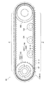
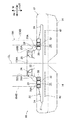
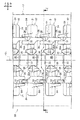
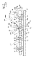
図1に示すように、第1実施形態に係る弾性クローラの一例としての無端状のゴムクローラ10は、クローラ車(例えば、トラクターなど)の駆動輪の一例としてのスプロケット100、遊動輪の一例としてのアイドラー102、及びスプロケット100とアイドラー102の間に配設される複数の転輪104に巻き掛けられて用いられるものである。
As shown in FIG. 1, an
なお、本実施形態のスプロケット100は、図1に示すように、クローラ車の駆動軸に取付けられる円盤状の輪部100Aの外周面に、周方向に一定間隔で歯部100Bを形成したものである。また、本実施形態のアイドラー102はクローラ車に回転支持される円盤状のものであり、転輪104は、クローラ車に回転支持される軸部104Aの軸方向両端部に軸部104Aよりも径が大きい輪部104Bを一対形成したものである。
In addition, as shown in FIG. 1, the
図1に示すように、スプロケット100、アイドラー102、転輪104、及びこれらに巻き掛けられたゴムクローラ10によってクローラ車の走行部としてのクローラ走行装置90が構成されている。
As shown in FIG. 1, a
なお、本実施形態では、無端状のゴムクローラ10の周方向(図中矢印S)を「クローラ周方向」と記載し、ゴムクローラ10の幅方向(図中矢印W)を「クローラ幅方向」と記載する。クローラ周方向とクローラ幅方向は、ゴムクローラ10を外周側または内周側(図2参照)から見た場合に直交している。
また、本実施形態では、ゴムクローラ10の内側(図中矢印IN)を「クローラ内側」と記載し、ゴムクローラ10の外側(図中矢印OUT)を「クローラ外側」と記載する。なお、クローラ外側はゴムクローラ10の接地側、クローラ内側はゴムクローラ10の接地側に対して反対側(反接地側)とそれぞれ言い換えられる。
In this embodiment, the circumferential direction of the endless rubber crawler 10 (arrow S in the figure) is described as “crawler circumferential direction”, and the width direction of the rubber crawler 10 (arrow W in the figure) is “crawler width direction”. It describes. The crawler circumferential direction and the crawler width direction are orthogonal to each other when the
In the present embodiment, the inside of the rubber crawler 10 (arrow IN in the figure) is described as “crawler inside”, and the outside of the rubber crawler 10 (arrow OUT in the figure) is described as “crawler outside”. In addition, the crawler outer side is paraphrased as the ground side of the
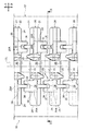
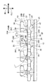
図1、図2に示すように、ゴムクローラ10は、ゴム材を無端帯状に形成したゴム体12を有している。なお、本実施形態のゴム体12は、本発明の弾性体の一例である。また、本実施形態の無端状のゴム体12の幅方向、周方向、内側、外側は、それぞれクローラ幅方向、クローラ周方向、クローラ内側、クローラ外側と一致している。
As shown in FIGS. 1 and 2, the
図2、図5に示すように、ゴム体12の内周部には、第1実施形態に係るクローラ用芯金20(以下、単に「芯金20」と記載する。)がクローラ周方向に間隔(本実施形態では一定間隔)をあけて複数配設されている。
As shown in FIGS. 2 and 5, a crawler core 20 (hereinafter, simply referred to as “
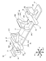
図2、図5に示すように、芯金20は、ゴム体12の内周部に配設され、クローラ幅方向(ゴム体12の幅方向)に延びて該クローラ幅方向に長くなる芯金基体21を有している。なお、芯金基体21の長手方向(以下、「芯金長手方向」と記載する。)とゴム体12の幅方向(クローラ幅方向)は一致している。また、芯金基体21の幅方向(以下、「芯金幅方向」と記載する。)は、ゴムクローラ10の平坦部分(スプロケット100やアイドラー102に巻き掛けられたりなどして湾曲した部分を除く部分であり、例えば、図1の符号Fで示す部分などを指す)において、ゴム体12の周方向(クローラ周方向)と一致している。このため、図3、図4では、芯金長手方向を矢印W、芯金幅方向を矢印Sで示している。
As shown in FIGS. 2 and 5, the cored
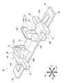
図3、図4に示すように、芯金基体21は、芯金長手方向の中央部22と、中央部22の芯金長手方向の両端部から延出する一対の翼部24と、を含んで構成されている。
As shown in FIGS. 3 and 4, the cored
中央部22は、スプロケット100が係合する部分であり、スプロケット100と係合して駆動力が入力されるため、翼部24よりも芯金厚み方向に肉厚とされている。なお、ここでいう「芯金厚み方向」とは、芯金長手方向及び芯金幅方向に対して直交する方向であり、ゴムクローラ10の上記平坦部分Fにおいては、ゴム体12の厚み方向(クローラ内外方向)と一致している。
The
図3、図4(A)に示すように、芯金20の中央部22の芯金長手方向の中心を通る直線(以下では、中心線CLと記載する)とゴム体12の幅方向の中心を通る直線(ゴム体12の中心線)は、一致している。すなわち、芯金20の中心線CLは、ゴムクローラ10の中心線と一致している。
As shown in FIGS. 3 and 4A, a straight line (hereinafter referred to as a center line CL) passing through the center of the
また、芯金20は、芯金基体21に芯金長手方向へ互いに間隔をあけて設けられ、この間隔がスプロケット100の通過スペースを形成する一対の突起26を有している。この突起26は、翼部24の根元部分に形成され、芯金厚み方向に沿って中央部22よりもクローラ内側へ突出している。また、一対の突起26間を通過するスプロケット100は、突起26の芯金長手方向内側の内壁に当接して、芯金長手方向への移動が規制されるようになっている。
The
図3及び図4(C)に示すように、突起26は、芯金側面視で(芯金長手方向から見て)突起中腹部26Aよりも突起先端部26Bが芯金幅方向両側に張り出した形状とされている。具体的には、図4(C)に示すように、突起先端部26Bは、芯金20の中央部22の芯金幅方向の中心を通る直線(以下では、中心線XLと記載する)からの距離が芯金幅方向の一方側よりも他方側で長くなっている。なお、以下では、突起先端部26Bの上記芯金幅方向の一方側へ張り出した部分を短張出部26C、上記芯金幅方向の他方側へ張り出した部分を長張出部26Dとして記載する。
As shown in FIGS. 3 and 4C, the
図4(A)に示すように、一対の突起26は、芯金20の中心線CLと中心線XLとの交点Pを中心として回転対称となるように配置されている。
As shown in FIG. 4A, the pair of
なお、本実施形態の突起26は、芯金側面視で突起中腹部26Aよりも突起先端部26Bが芯金幅方向両側に張り出した形状とされているが、この構成に限定されず、例えば、突起26は、芯金側面視で突起根元部から突起先端部に向かって先細る形状としてもよい。また、本実施形態の一対の突起26は、交点Pを中心として回転対称となるように配設されているが、この構成に限定されず、芯金20の中心線CLに対して左右対称となるように配設されてもよい。
Incidentally, the
図3、図4(A)に示すように、芯金20は、芯金基体21の一対の突起26を挟んで芯金長手方向両外側に設けられ、芯金幅方向に延び、転輪104の一対の輪部104Bを支持する一対の転輪支持部28を有している。この転輪支持部28のクローラ内側の面28A(以下では、「転輪支持面28A」と記載する。)は、平坦状とされ、輪部104Bの外周面が接触しながら転動するようになっている。
なお、ここでいう「芯金長手方向外側」とは、中心線CLから芯金長手方向に沿って離間する側を指し、「芯金長手方向内側」とは、中心線CLに沿ってこの中心線CLに向かう側を指している。
As shown in FIGS. 3 and 4A, the
Here, the “core metal longitudinal direction outside” refers to a side separated from the center line CL along the core metal longitudinal direction, and the “core metal longitudinal direction inside” refers to the center line CL along the center line CL. It points to the side toward the line CL.
図3、図4(A)に示すように、転輪支持部28の芯金幅方向の一端側には、本発明の係合部の一例としての係合用凸部32が設けられている。具体的には、係合用凸部32は、転輪支持部28の芯金幅方向の一端部に形成され、この一端部から芯金幅方向へ突出する略直方体状の突起とされている。また、図4(C)に示すように、この係合用凸部32のクローラ内側の面は、転輪支持部28の転輪支持面28Aに連なり(本実施形態では連続している)、転輪支持面28Aを芯金幅方向に延長している。
As shown in FIGS. 3 and 4A, an engaging
図3、図4(A)に示すように、転輪支持部28の芯金幅方向の他端側には、本発明の被係合部の一例としての係合用凹部34が設けられている。具体的には、係合用凹部34は、転輪支持部28の芯金幅方向の他端部に形成され、この他端部から芯金幅方向に沿って延びかつ芯金厚み方向に開放された窪みとされている。なお、本実施形態では、転輪支持部28の他端部を二股形状とし、この二股形状部分(以下、「二股部36」と記載する。)によって上記係合用凹部34を形成している。この転輪支持部28の係合用凹部34は、芯金長手方向の長さが係合用凸部32の芯金長手方向の長さよりも長く、図2に示すように、クローラ周方向の他方に隣り合う転輪支持部28の係合用凸部32を受け入れられるようになっている。
As shown in FIGS. 3 and 4A, an engaging
図2に示すように、転輪支持部28の係合用凸部32は、クローラ周方向の一方(一側)に隣り合う転輪支持部28の係合用凹部34に差し込まれている。また、転輪支持部28の係合用凹部34には、クローラ周方向の他方(他側)に隣り合う転輪支持部28の係合用凸部32が差し込まれている。上記のように、係合用凸部32を係合用凹部34に差し込んだ状態で、芯金20はゴム体12の内周部にクローラ周方向に間隔をあけて配設されている。
As shown in FIG. 2, the engaging
図6に示すように、転輪支持部28の係合用凹部34に、クローラ周方向の他方に隣り合う転輪支持部28の係合用凸部32が差し込まれているときには、芯金側面視で転輪支持部28の二股部36と、隣り合う転輪支持部28の係合用凸部32とが重なり合っている。
As shown in FIG. 6, when the engaging
図3、図4(A)に示すように、本実施形態では、芯金20の中心線XLを境にして、突起26の短張出部26C側に転輪支持部28の二股部36が形成されている。しかし、本発明はこの構成に限定されず、芯金20の中心線CLを境にして、突起26の長張出部26D側に転輪支持部28の二股部36が形成されていてもよい。
As shown in FIGS. 3 and 4A, in the present embodiment, the
なお、本実施形態の一対の転輪支持部28は、芯金20の交点Pを中心として回転対称となるように配置されているが、本発明はこの構成に限定されず、芯金20の中心線CLに対して左右対称となるように配置されてもよい。
In addition, although a pair of
図5に示すように、芯金20の少なくとも一対の翼部24を含むクローラ外側部分は、ゴム体12の内周部に埋設されている。また、図6に示すように、突起26は、ゴム材により被覆されてゴム体12の内周部にクローラ内側に突出するゴム突起16を形成している。このゴム突起16は、クローラ幅方向から見て略台形状となっている。
As shown in FIG. 5, the crawler outer side portion including at least the pair of
図2に示すように、ゴム体12の内周部には、クローラ周方向に隣り合う芯金20同士の中央部22間にスプロケット100の歯部100Bが挿入係合される係合凹部40が形成されている。この係合凹部40は、底部がゴム材により閉鎖されている。なお、本発明に係るその他の実施形態では、係合凹部40の底部にクローラ内外に貫通するスリット(切り欠き)を形成してもよく、また、ゴム体12に、係合凹部40の代わりにクローラ内外に貫通する貫通穴を形成し、該貫通穴に歯部100Bを挿入係合させる構成としてもよい。
As shown in FIG. 2, an
ここで、スプロケット100の歯部100Bが係合凹部40に挿入係合した状態でスプロケット100が回転(駆動)すると、歯部100Bが係合(当接)している係合凹部40を構成するクローラ周方向のゴム壁を介して芯金20の中央部22に駆動力が入力されて、ゴム体12(ゴムクローラ10)に駆動力が伝達される。
Here, when the
図5に示すように、ゴム体12の芯金20のクローラ外側には、係合凹部40を挟んでクローラ幅方向両側にクローラ周方向に沿って延びる無端帯状の補強層42が埋設されている。この補強層42は、クローラ周方向に沿って螺旋状に巻回された1本の補強コード又はクローラ周方向に沿って並列された複数本の補強コードをゴム被覆して形成されている。なお、本実施形態においては、引張り強度に優れるスチールコードを補強コードとして用いるが、本発明はこの構成に限定されず、十分な引張り強度を有していれば、例えば、有機繊維などで構成したコードを補強コードとして用いてもよい。
As shown in FIG. 5, an endless belt-shaped reinforcing
また、図1に示すように、ゴム体12の外周部には、クローラ外側に突出するゴム材により構成されたラグ14がクローラ周方向に間隔をあけて複数形成されている。なお、このラグ14は、ゴムクローラ10の地面に接地する部位である。
As shown in FIG. 1, a plurality of
次に、本実施形態の芯金20及びゴムクローラ10の作用効果について説明する。
ゴムクローラ10の走行時には、スプロケット100、アイドラー102、及び複数の転輪104に巻き掛けられたゴムクローラ10がスプロケット100、アイドラー102、及び複数の転輪104の間で循環する。このとき、スプロケット100及びアイドラー102は、一対の突起26間に形成された通過スペースを通過し、図5に示すように、転輪104の一対の輪部104Bは、一対の転輪支持部28上を通過する。
Next, the effect of the
During traveling of the
図2に示すように、ゴムクローラ10に複数配設された芯金20では、転輪支持部28の係合用凸部32をクローラ周方向の一方に隣り合う転輪支持部28の係合用凹部34に差し込み、転輪支持部28の係合用凹部34にクローラ周方向の他方に隣り合う転輪支持部28の係合用凸部32が差し込まれている。このため、隣り合う芯金20同士を芯金長手方向(クローラ幅方向)へ相対変位(横ずれ)させる力が芯金20に作用した場合、係合用凹部34の側壁(芯金長手方向の側壁)とこれに差し込まれた係合用凸部32の側壁(芯金長手方向の側壁)とが係合(当接)して、隣り合う転輪支持部28同士の横ずれが抑制される。ここで、本実施形態では、図2に示すように、隣り合う芯金20同士に上記横ずれを生じさせる力が作用していない場合には、係合用凹部34の上記側壁とこれに差し込まれた係合用凸部32の上記側壁とが係合(当接)しない状態が維持されるようになっている。なお、本発明のその他の実施形態では、隣り合う芯金20同士に上記横ずれを生じさせる力が作用していなくても係合用凹部34の上記側壁とこれに差し込まれた係合用凸部32の上記側壁とが係合(当接)状態となる構成としてもよい。
As shown in FIG. 2, in the cored
ここで、芯金20では、転輪支持部28の芯金幅方向の一端側に係合用凸部32を形成し、他端部に係合用凹部34を形成していることから、例えば、転輪支持部28とは別の部位に横ずれ防止用の突起などを形成するものと比べて、芯金20の重量の増加を抑制することができる。
Here, in the
以上のことから、芯金20によれば、隣り合う芯金20同士の横ずれを抑制することができるとともに重量の増加を抑制することができる。
From the above, according to the cored
また、ゴムクローラ10に複数配設された芯金20では、図6に示すように、クローラ側面視で、転輪支持部28の転輪支持面28Aとこれに隣り合う転輪支持部28の転輪支持面28Aとが交わっていることから、転輪104の輪部104Bが転輪支持部28から隣り合う転輪支持部28へ乗り移る際には、転輪支持部28の係合用凸部32と隣り合う転輪支持部28の係合用凹部34とで転輪104からの荷重が支持されるため、転輪104の下方への落ち込みが少なくなる。
これにより、転輪104の輪部104Bが一方の芯金20から隣り合う他方の芯金20へ乗り移る際の、転輪104の振動が抑制される。
Further, in the
Thereby, the vibration of the
また、芯金20では、転輪支持部28の芯金幅方向の一端側に係合用凸部32を形成し、他端側に係合用凹部34を形成するという簡単な構造で隣り合う芯金20同士の横ずれを確実に抑制することができる。
Further, the cored
よって、ゴムクローラ10では、上記のような芯金20を用いていることから、隣り合う芯金20同士の横ずれが抑制され、さらに、重量の増加も抑制される。
Therefore, in the
(第2実施形態)
次に、本発明の第2実施形態に係るクローラ用芯金及び弾性クローラについて図1、
図7〜図11を参照しながら説明する。なお、第1実施形態と同一構成には同一符号を付し、その説明は省略する。また、図7、図10、図11では、ゴム材により形成されるゴム体12、ラグ14、及びゴム突起16を二点鎖線で示している。
(Second Embodiment)
Next, a crawler mandrel and an elastic crawler according to a second embodiment of the present invention will be described with reference to FIG.
This will be described with reference to FIGS. In addition, the same code | symbol is attached | subjected to the same structure as 1st Embodiment, and the description is abbreviate | omitted. Moreover, in FIG.7, FIG.10, FIG.11, the
図1に示すように、第2実施形態に係るゴムクローラ50は、第1実施形態と同じ構成のゴム体12と、ラグ14と、補強層42と、後述する第2実施形態に係るクローラ用芯金52(以下、単に「芯金52」と記載する。)と、を有している。なお、本実施形態では第1実施形態と同様に、ゴムクローラ50の周方向、幅方向、内側、外側を、それぞれクローラ周方向、クローラ幅方向、クローラ内側、クローラ外側と記載する。
As shown in FIG. 1, a
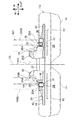
図7に示すように、ゴム体12の内周部には、本発明の第2実施形態に係るクローラ用芯金52がクローラ周方向に間隔(本実施形態では一定間隔)をあけて複数配設されている。また、芯金52は、第1実施形態と同じ構成の芯金基体21を有している。
As shown in FIG. 7, a plurality of
なお、本実施形態でも第1実施形態と同様に、芯金基体21の長手方向(以下、「芯金長手方向」と記載する。)とゴム体12の幅方向(クローラ幅方向)は一致している。また、芯金基体21の幅方向(以下、「芯金幅方向」と記載する。)は、ゴムクローラ10の平坦部分(スプロケット100やアイドラー102に巻き掛けられたりなどして湾曲した部分を除く部分であり、例えば、図1の符号Fで示す部分などを指す)において、ゴム体12の周方向(クローラ周方向)と一致している。このため、図8、図9では、芯金長手方向を矢印W、芯金幅方向を矢印Sで示している。
In this embodiment, as in the first embodiment, the longitudinal direction of the core metal base 21 (hereinafter referred to as “core metal longitudinal direction”) and the width direction of the rubber body 12 (crawler width direction) coincide. ing. Further, the width direction of the core metal base 21 (hereinafter referred to as “core width direction”) is a flat portion of the rubber crawler 10 (excluding a curved portion wound around the
図8、図9に示すように、芯金52は、第1実施形態と同じ構成の一対の突起26と、一対の転輪支持部28とを備えている。また、芯金52の中央部22の芯金長手方向の中心を通る直線(以下では、中心線CLと記載する)とゴム体12の幅方向の中心を通る中心線は、一致している。すなわち、芯金52の中心線CLは、ゴムクローラ50の中心線と一致している。
As shown in FIGS. 8 and 9, the cored
また、本実施形態では、図9(A)に示すように、芯金20の中心線XLを境にして、突起26の短張出部26C側に転輪支持部28の二股部36が形成されている。
Further, in the present embodiment, as shown in FIG. 9A, the
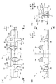
図8、図9(B)に示すように、転輪支持部28の係合用凹部34を構成する二股部36の突起26側には、突起26の突出方向(図中矢印IN側)に隆起するとともに芯金幅方向に延びる内隆起部54が設けられている。具体的には、内隆起部54は、二股部36を構成する対向配置された一対のレール部のうち、突起26側(芯金長手方向内側)のレール部上に設けられている。
As shown in FIGS. 8 and 9B, the
また、内隆起部54は、二股部36の先端部から中心線XL近傍まで延びており、転輪支持部28の転輪支持面28A上を通過する輪部104Bの芯金長手方向の移動を該輪部104Bに当接して規制するようになっている。
Further, the inner raised
次に、本実施形態の芯金52及びゴムクローラ50の作用効果について説明する。
なお、本実施形態の作用効果のうち、第1実施形態と同様の作用効果については、その説明を省略する。
Next, the effect of the
In addition, the description about the effect similar to 1st Embodiment among the effects of this embodiment is abbreviate | omitted.
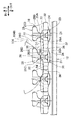
図10に示すように、芯金52では、二股部36の突起26側に内隆起部54を設けていることから、転輪支持部28上を通過する一対の輪部104Bの突起26側への移動が内隆起部54に当接して規制される。特に、図11に示すように、内隆起部54は、突起26の短張出部26C側に延出していることから、輪部104Bの芯金長手方向への移動が突起26の長張出部26Dと内隆起部54とで規制される。つまり、芯金幅方向(クローラ周方向)に広い範囲で、輪部104Bの芯金長手方向(クローラ幅方向)への移動を規制することができ、輪部104Bが突起26(ゴム突起16)を乗り越えるのを効果的に抑制することができる。
As shown in FIG. 10, in the cored
また、第2実施形態では、内隆起部54が芯金幅方向に連続して延びる構成としているが、本発明はこの構成に限定されず、内隆起部54が芯金幅方向に断続して延びる構成(例えば、内隆起部54を芯金幅方向に断続的に複数設ける構成)としてもよい。
Moreover, in 2nd Embodiment, although it is set as the structure by which the internal protruding
(第3実施形態)
次に、本発明の第3実施形態に係るクローラ用芯金及び弾性クローラについて図1、
図12〜図16を参照しながら説明する。なお、第1実施形態と同一構成には同一符号を付し、その説明は省略する。また、図12、図15、図16では、ゴム材により形成されるゴム体12、ラグ14、及びゴム突起16を二点鎖線で示している。
(Third embodiment)
Next, a crawler core bar and an elastic crawler according to a third embodiment of the present invention will be described with reference to FIG.
This will be described with reference to FIGS. In addition, the same code | symbol is attached | subjected to the same structure as 1st Embodiment, and the description is abbreviate | omitted. In FIG. 12, FIG. 15, and FIG. 16, the
図1に示すように、第3実施形態に係るゴムクローラ60は、第1実施形態と同じ構成のゴム体12と、ラグ14と、補強層42と、後述する第3実施形態に係るクローラ用芯金62(以下、単に「芯金62」と記載する。)と、を有している。なお、本実施形態では第1実施形態と同様に、ゴムクローラ60の周方向、幅方向、内側、外側を、それぞれクローラ周方向、クローラ幅方向、クローラ内側、クローラ外側と記載する。
As shown in FIG. 1, a
図12に示すように、ゴム体12の内周部には、本発明の第3実施形態に係るクローラ用芯金62がクローラ周方向に間隔(本実施形態では一定間隔)をあけて複数配設されている。また、芯金62は、第1実施形態と同じ構成の芯金基体21を有している。
As shown in FIG. 12, a plurality of
なお、本実施形態でも第1実施形態と同様に、芯金基体21の長手方向(以下、「芯金長手方向」と記載する。)とゴム体12の幅方向(クローラ幅方向)は一致している。また、芯金基体21の幅方向(以下、「芯金幅方向」と記載する。)は、ゴムクローラ10の平坦部分(スプロケット100やアイドラー102に巻き掛けられたりなどして湾曲した部分を除く部分であり、例えば、図1の符号Fで示す部分などを指す)において、ゴム体12の周方向(クローラ周方向)と一致している。このため、図13、図14では、芯金長手方向を矢印W、芯金幅方向を矢印Sで示している。
In this embodiment, as in the first embodiment, the longitudinal direction of the core metal base 21 (hereinafter referred to as “core metal longitudinal direction”) and the width direction of the rubber body 12 (crawler width direction) coincide. ing. Further, the width direction of the core metal base 21 (hereinafter referred to as “core width direction”) is a flat portion of the rubber crawler 10 (excluding a curved portion wound around the
図13、図14に示すように、芯金62は、第1実施形態と同じ構成の一対の突起26と、一対の転輪支持部28とを備えている。また、芯金62の中央部22の芯金長手方向の中心を通る直線(以下では、中心線CLと記載する)とゴム体12の幅方向の中心を通る中心線は、一致している。すなわち、芯金62の中心線CLは、ゴムクローラ60の中心線と一致している。
As shown in FIGS. 13 and 14, the cored
また、本実施形態では、図14(A)に示すように、芯金20の中心線XLを境にして、突起26の長張出部26D側に転輪支持部28の二股部36が形成されている。しかし、本発明はこの構成に限定されず、芯金20の中心線CLを境にして、突起26の短張出部26C側に転輪支持部28の二股部36が形成されていてもよい。
Further, in the present embodiment, as shown in FIG. 14A, the
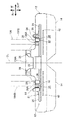
図13、図14(B)に示すように、転輪支持部28の係合用凹部34を構成する二股部36の突起26側よりも芯金長手方向外側には、突起26の突出方向(図中矢印IN側)に隆起するとともに芯金幅方向に延びる外隆起部64が設けられている。具体的には、外隆起部64は、二股部36を構成する対向配置された一対のレール部のうち、突起26側よりも芯金長手方向外側のレール部上に設けられている。
As shown in FIGS. 13 and 14B, the
また、外隆起部64は、二股部36の先端部から中心線XL近傍まで延びており、転輪支持部28の転輪支持面28A上を通過する輪部104Bの芯金長手方向の移動を該輪部104Bに当接して規制するようになっている。
Further, the outer raised
次に、本実施形態の芯金62及びゴムクローラ60の作用効果について説明する。
なお、本実施形態の作用効果のうち、第1実施形態と同様の作用効果については、その説明を省略する。
Next, the effect of the
In addition, the description about the effect similar to 1st Embodiment among the effects of this embodiment is abbreviate | omitted.
図15に示すように、芯金62では、二股部36の突起26側よりも芯金長手方向外側に外隆起部64を設けていることから、転輪支持部28上を通過する一対の輪部104Bの芯金長手方向外側への移動が外隆起部64に当接して規制される。また、図16に示すように、外隆起部64は、芯金幅方向に延出していることから、輪部104Bの芯金長手方向への移動を芯金幅方向に広い範囲で抑制することができる。特に、ゴムクローラ60が傾斜走行した場合に、傾斜方向下側に位置する輪部104Bが傾斜方向下側に位置する転輪支持部28から離れたとしても、傾斜方向上側に位置する輪部104Bが外隆起部64に当接して芯金長手方向の移動が規制されるため、傾斜方向下側に位置する輪部104Bが傾斜方向下側に位置するゴム突起16に乗り上げて、乗り越えるのを効果的に抑制することができる。
As shown in FIG. 15, in the
また、第3実施形態では、外隆起部64が芯金幅方向に連続して延びる構成としているが、本発明はこの構成に限定されず、外隆起部64が芯金幅方向に断続して延びる構成(例えば、外隆起部64を芯金幅方向に断続的に複数設ける構成)としてもよい。
Moreover, in 3rd Embodiment, although it is set as the structure which the outer protruding
(その他の実施形態)
第1〜第3の実施形態では、一対の突起26を、交点Pを中心として回転対称となるように配置しているが、本発明はこの構成に限定されず、中心線CL上の交点Pを含まない任意の一点を中心として回転対称となるように配置してもよい。なお、一対の転輪支持部28についても同様に、第1〜第3の実施形態では、一対の転輪支持部28を、交点Pを中心として回転対称となるように配置しているが、本発明はこの構成に限定されず、中心線CL上の交点Pを含まない任意の一点を中心として回転対称となるように配置してもよい。
(Other embodiments)
In the first to third embodiments, the pair of
第2実施形態では二股部36の突起26側のレール部に内隆起部54を形成し、第3実施形態では、二股部36の突起26側よりも芯金長手方向外側のレール部に外隆起部64を形成しているが、本発明はこの構成に限定されず、二股部36の突起26側のレール部に内隆起部54を形成し、二股部36の突起26側よりも芯金長手方向外側のレール部に外隆起部64を形成して、転輪支持部28の内隆起部54と外隆起部64との間を輪部104Bの通過スペースとする構成としてもよい。
In the second embodiment, an inner raised
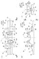
前述の各実施形態では、転輪支持部28の一端部に係合用凸部32を形成し、他端部に係合用凹部34を形成する構成としているが、本発明はこの構成に限定されず、図17(A)に示すように、転輪支持部28の一端部に複数の係合用凸部70を形成し、転輪支持部28の他端部に複数の係合用凹部72を形成して、転輪支持部28の係合用凸部70をクローラ周方向の一方に隣り合う転輪支持部28の係合用凹部72に差し込む構成としてもよい。
In each of the embodiments described above, the engaging
また、前述の各実施形態では、転輪支持部28の係合用凸部32の芯金長手方向の長さを根元部から先端部まで略一定としているが、本発明はこの構成に限定されず、係合用凸部32の芯金長手方向の長さを根元部から先端部に向かって短くする構成としてもよい。 また、図17(B)に示すように、係合用凸部74の先端部74Aを根元部74Bよりも芯金長手方向の長さを長くした形状(図17(B)に示す転輪支持部28の要部平面視では、先端部74Aは円形状)とし、係合用凹部76を芯金厚み方向からのみ係合用凸部74が差し込める形状(図17(B)に示す転輪支持部28の要部平面視では、開口部76Bは係合用凸部74の根元部74Bに対応した形状であり先端部74Aよりも芯金長手方向の長さが短く、中間部分76Aは先端部74Aよりも大径な円形状)とする構成としてもよい。この場合には、隣り合う転輪支持部28の横ずれに加えて、係合用凸部74の先端部74Aと、係合用凹部76の開口部76Bとの当接(引っ掛かり)により、隣り合う転輪支持部28の間隔が離れるのを抑制することもできる。
Further, in each of the above-described embodiments, the length in the longitudinal direction of the core metal of the engaging
前述した各実施形態では、ゴム体12の中心線と芯金20、52、62の中心線CLとが一致しているが、本発明はこの構成に限定されず、ゴム体12の中心線に対して芯金20、52、62の中心線CLがクローラ幅方向にずれていてもよい。
In each of the above-described embodiments, the center line of the
また、前述した実施形態では、ゴムクローラ10の補強用に補強層42を埋設しているが、本発明はこの構成に限定されず、補強層42を用いずに、クローラ周方向に互いに隣接する芯金20(52、62)同士を連結部材(例えば、リング状の連結部材など)で連結、又は、芯金に形成した連結部同士(例えば、フックとピンなど)を連結し、この連結して無端状とした芯金でゴムクローラ10を補強する構成としてもよい。
In the above-described embodiment, the reinforcing
さらに、前述した実施形態では、本発明の無端帯状の弾性体の一例を、ゴム材を無端帯状に形成したゴム体12としているが、本発明はこの構成に限定されず、上記弾性体の一例としては、ゴム以外のエラストマーなどを無端帯状に形成した帯状体であってもよい。
Furthermore, in the above-described embodiment, an example of the endless belt-like elastic body of the present invention is the
以上、実施形態を挙げて本発明の実施の形態を説明したが、これらの実施形態は一例であり、要旨を逸脱しない範囲内で種々変更して実施できる。また、本発明の権利範囲がこれらの実施形態に限定されないことは言うまでもない。 The embodiments of the present invention have been described above with reference to the embodiments. However, these embodiments are merely examples, and various modifications can be made without departing from the scope of the invention. It goes without saying that the scope of rights of the present invention is not limited to these embodiments.
10 ゴムクローラ(弾性クローラ)
12 ゴム体(弾性体)
20 芯金(クローラ用芯金)
26 突起
28 転輪支持部
32 凸部(係合部または被係合部)
34 凹部(被係合部または係合部)
50 ゴムクローラ(弾性クローラ)
52 芯金(クローラ用芯金)
54 内隆起部
60 ゴムクローラ(弾性クローラ)
62 芯金(クローラ用芯金)
64 外隆起部
100 スプロケット(駆動輪)
104 転輪
104B 輪部
CL 中心線
XL 中心線
S クローラ周方向、芯金幅方向
W クローラ幅方向、芯金長手方向
IN クローラ内側
OUT クローラ外側
10 Rubber crawler (elastic crawler)
12 Rubber body (elastic body)
20 Core (Crawler core)
26 Protrusions 28 Rolling
34 Recess (engaged part or engaged part)
50 Rubber crawler (elastic crawler)
52 Core (Crawler core)
54
62 Core (Crawler core)
64
Claims (5)
前記芯金基体に該芯金基体の長手方向へ互いに間隔をあけて設けられ、該間隔が前記駆動輪の通過スペースを形成する突起と、
前記突起の前記芯金基体長手方向外側に設けられ、前記芯金基体の幅方向に延び、前記転輪に設けられた輪部を支持する転輪支持部と、
前記転輪支持部の前記芯金基体幅方向の一端側に設けられるとともに、当該芯金基体幅方向の一端部から突出する凸部で構成され、前記弾性体の周方向の一方に隣り合う前記転輪支持部の被係合部と係合する係合部と、
前記転輪支持部の前記芯金基体幅方向の他端側に設けられるとともに、前記凸部を受け入れる凹部で構成され、前記弾性体の周方向の他方に隣り合う前記転輪支持部の係合部と係合する被係合部と、
を有し、
前記凹部の前記突起側に、前記突起の突出方向に隆起するとともに前記芯金基体幅方向に延び、前記輪部に当接して該輪部の前記芯金基体長手方向への移動を規制する内隆起部を設け、該内隆起部を前記芯金基体の幅方向の端縁より前記芯金基体幅方向へ突出させたクローラ用芯金。 A core metal base disposed at an inner circumferential portion of an endless belt-like elastic body wound around a drive wheel and a wheel at a distance in the circumferential direction of the elastic body, and long in the width direction of the elastic body;
Protrusions that are provided on the cored bar base so as to be spaced apart from each other in the longitudinal direction of the cored bar base, and the spacing forms a passage space for the drive wheel;
A wheel support portion provided outside the core metal base in the longitudinal direction of the protrusion, extending in a width direction of the core metal base, and supporting a wheel provided on the wheel;
The roller support portion is provided on one end side in the core metal substrate width direction of the roller support portion, and is configured by a convex portion protruding from one end portion in the core metal substrate width direction, and adjacent to one of the circumferential directions of the elastic body. An engaging portion that engages with an engaged portion of the wheel support portion;
Engagement of the roller support portion provided on the other end side in the core metal substrate width direction of the roller support portion and configured by a recess for receiving the protrusion, and adjacent to the other in the circumferential direction of the elastic body An engaged portion that engages with the portion;
Have
The protrusion protrudes in the protruding direction of the protrusion and extends in the width direction of the core metal base, contacts the ring portion, and restricts the movement of the ring portion in the longitudinal direction of the core metal substrate. A crawler core bar provided with an inner bulge portion and projecting the inner bulge portion from an edge in the width direction of the core metal substrate in the width direction of the core metal substrate.
前記芯金基体に該芯金基体の長手方向へ互いに間隔をあけて設けられ、該間隔が前記駆動輪の通過スペースを形成する突起と、
前記突起の前記芯金基体長手方向外側に設けられ、前記芯金基体の幅方向に延び、前記転輪に設けられた輪部を支持する転輪支持部と、
前記転輪支持部の前記芯金基体幅方向の一端側に設けられるとともに、当該芯金基体幅方向の一端部から突出する凸部で構成され、前記弾性体の周方向の一方に隣り合う前記転輪支持部の被係合部と係合する係合部と、
前記転輪支持部の前記芯金基体幅方向の他端側に設けられるとともに、当該芯金基体幅方向の他端部に形成され前記凸部を受け入れる凹部で構成され、前記弾性体の周方向の他方に隣り合う前記転輪支持部の係合部と係合する被係合部と、
を有し、
前記凹部の前記突起側よりも前記芯金基体長手方向外側に、前記突起の突出方向に隆起するとともに前記芯金基体幅方向に延び、前記輪部に当接して該輪部の前記芯金基体長手方向への移動を規制する外隆起部を設け、該外隆起部を前記芯金基体の幅方向の端縁より前記芯金基体幅方向へ突出させたクローラ用芯金。 A core metal base disposed at an inner circumferential portion of an endless belt-like elastic body wound around a drive wheel and a wheel at a distance in the circumferential direction of the elastic body, and long in the width direction of the elastic body;
Protrusions that are provided on the cored bar base so as to be spaced apart from each other in the longitudinal direction of the cored bar base, and the spacing forms a passage space for the drive wheel;
A wheel support portion provided outside the core metal base in the longitudinal direction of the protrusion, extending in a width direction of the core metal base, and supporting a wheel provided on the wheel;
The roller support portion is provided on one end side in the core metal substrate width direction of the roller support portion, and is configured by a convex portion protruding from one end portion in the core metal substrate width direction, and adjacent to one of the circumferential directions of the elastic body. An engaging portion that engages with an engaged portion of the wheel support portion;
The roller support portion is provided on the other end side in the core metal substrate width direction of the roller support portion, and is configured by a recess formed on the other end portion in the core metal substrate width direction to receive the convex portion, and the circumferential direction of the elastic body An engaged part that engages with an engaging part of the wheel support part adjacent to the other of
Have
The core metal of the ring part protrudes in the protruding direction of the protrusion and extends in the width direction of the core metal base in the longitudinal direction outside the core metal base side of the protrusion side of the recess, and abuts against the ring part. A crawler core bar provided with an outer bulge portion that restricts movement in the longitudinal direction of the base body, and the outer bulge portion projecting in the width direction of the core bar base body from an edge in the width direction of the core bar base body.
前記内隆起部を前記芯金基体長手方向の中心を通る中心線を境とした一方側及び他方側のそれぞれに設け、一方の内隆起部を前記芯金基体幅方向の一方側に突出させるとともに、他方の内隆起部を前記芯金基体幅方向の他方側に突出させた請求項1に記載のクローラ用芯金。 A short projecting portion projecting to one side in the core metal substrate width direction and a long projecting portion projecting to the other side in the core metal substrate width direction and having a projecting amount larger than the short projecting portion are formed on the protrusion. Provided,
The inner bulging portion is provided on each of one side and the other side with a center line passing through the center in the longitudinal direction of the core metal base as a boundary, and one of the inner ridges protrudes to one side in the width direction of the core metal base. The crawler core bar according to claim 1, wherein the other inner protruding portion is projected to the other side in the width direction of the core metal substrate .
前記外隆起部を前記芯金基体長手方向の中心を通る中心線を境とした一方側及び他方側のそれぞれに設け、一方の外隆起部を前記芯金基体幅方向の一方側に突出させるとともに、他方の外隆起部を前記芯金基体幅方向の他方側に突出させた請求項2に記載のクローラ用芯金。 A short projecting portion projecting to one side in the core metal substrate width direction and a long projecting portion projecting to the other side in the core metal substrate width direction and having a projecting amount larger than the short projecting portion are formed on the protrusion. Provided,
The outer bulge portion is provided on each of one side and the other side with a center line passing through the center in the longitudinal direction of the core metal substrate as a boundary, and one of the outer bulge portions protrudes to one side in the width direction of the core metal substrate. In addition, the core for a crawler according to claim 2, wherein the other outer protruding portion protrudes to the other side in the core metal base width direction .
前記弾性体の内周部に前記弾性体の周方向へ間隔をあけて配設された請求項1〜4のいずれか1項に記載のクローラ用芯金と、を有する弾性クローラ。 An endless belt-like elastic body wound around the driving wheel and the rolling wheel;
The elastic crawler which has the metal core for crawlers of any one of Claims 1-4 arrange | positioned in the inner peripheral part of the said elastic body at intervals in the circumferential direction of the said elastic body.
Priority Applications (1)
| Application Number | Priority Date | Filing Date | Title |
|---|---|---|---|
| JP2011092370A JP5836627B2 (en) | 2011-04-18 | 2011-04-18 | Crawler mandrel and elastic crawler |
Applications Claiming Priority (1)
| Application Number | Priority Date | Filing Date | Title |
|---|---|---|---|
| JP2011092370A JP5836627B2 (en) | 2011-04-18 | 2011-04-18 | Crawler mandrel and elastic crawler |
Publications (2)
| Publication Number | Publication Date |
|---|---|
| JP2012224161A JP2012224161A (en) | 2012-11-15 |
| JP5836627B2 true JP5836627B2 (en) | 2015-12-24 |
Family
ID=47274842
Family Applications (1)
| Application Number | Title | Priority Date | Filing Date |
|---|---|---|---|
| JP2011092370A Expired - Fee Related JP5836627B2 (en) | 2011-04-18 | 2011-04-18 | Crawler mandrel and elastic crawler |
Country Status (1)
| Country | Link |
|---|---|
| JP (1) | JP5836627B2 (en) |
Families Citing this family (9)
| Publication number | Priority date | Publication date | Assignee | Title |
|---|---|---|---|---|
| JP6996739B2 (en) * | 2017-11-24 | 2022-01-17 | 福山ゴム工業株式会社 | Core metal for elastic crawlers and elastic crawlers |
| JP7122213B2 (en) * | 2018-10-09 | 2022-08-19 | 株式会社ブリヂストン | Metal core for elastic crawler and elastic crawler using the metal core |
| JP2020142683A (en) * | 2019-03-07 | 2020-09-10 | 株式会社ブリヂストン | Core grid for crawler and elastic crawler |
| CN110027640A (en) * | 2019-05-29 | 2019-07-19 | 北京北方车辆集团有限公司 | A kind of rubberbelt type caterpillar core gold structure |
| JP7002595B2 (en) * | 2020-05-12 | 2022-01-20 | 鎔宰 崔 | Elastic crawler |
| CN112660259B (en) * | 2020-11-17 | 2023-03-03 | 崔镕宰 | Elastic crawler belt |
| JP7271074B2 (en) * | 2021-08-18 | 2023-05-11 | 鎔宰 崔 | elastic crawler |
| JP7754972B2 (en) * | 2024-03-19 | 2025-10-15 | ゼニス産業株式会社 | Elastic Crawler |
| JP7754973B2 (en) * | 2024-03-19 | 2025-10-15 | ゼニス産業株式会社 | Elastic Crawler |
Family Cites Families (5)
| Publication number | Priority date | Publication date | Assignee | Title |
|---|---|---|---|---|
| JPH0728067Y2 (en) * | 1988-05-27 | 1995-06-28 | セイレイ工業株式会社 | Track structure of running parts such as backhoe |
| JPH0288889U (en) * | 1988-07-13 | 1990-07-13 | ||
| JP2508801Y2 (en) * | 1989-04-27 | 1996-08-28 | 株式会社小松製作所 | Mandrel for rubber crawler |
| JP3917243B2 (en) * | 1997-06-15 | 2007-05-23 | 株式会社ブリヂストン | Rubber corer for rubber crawler and rubber crawler using the same |
| JP2000159160A (en) * | 1998-09-24 | 2000-06-13 | Bridgestone Corp | Rubber crawler |
-
2011
- 2011-04-18 JP JP2011092370A patent/JP5836627B2/en not_active Expired - Fee Related
Also Published As
| Publication number | Publication date |
|---|---|
| JP2012224161A (en) | 2012-11-15 |
Similar Documents
| Publication | Publication Date | Title |
|---|---|---|
| JP5836627B2 (en) | Crawler mandrel and elastic crawler | |
| JP2014015156A (en) | Rubber crawler | |
| US7883160B2 (en) | Elastic crawler and elastic crawler manufacturing method | |
| JP2010215063A (en) | Core metal and elastic crawler | |
| JP2010111355A (en) | Elastic crawler | |
| US9290218B2 (en) | Crawler core for member and rubber crawler | |
| JP5213377B2 (en) | Rubber crawler | |
| JP2013166475A (en) | Elastic crawler | |
| JP5676141B2 (en) | Crawler mandrel and rubber crawler | |
| JP2012096638A (en) | Elastic crawler | |
| JP5770560B2 (en) | Elastic crawler and crawler traveling device | |
| JP2018177072A (en) | Elastic crawler | |
| JP4907230B2 (en) | Elastic track | |
| JP7367403B2 (en) | Elastic crawler and core material | |
| JP2013010444A (en) | Core metal for crawler and elastic crawler | |
| JP4560333B2 (en) | Elastic crawler | |
| JP5808629B2 (en) | Core metal and elastic crawler for crawler | |
| JP5683991B2 (en) | Rubber crawler | |
| JP7310375B2 (en) | elastic crawler | |
| JP7122213B2 (en) | Metal core for elastic crawler and elastic crawler using the metal core | |
| JP4898278B2 (en) | Elastic crawler | |
| JP5567461B2 (en) | Core metal and elastic crawler for crawler | |
| JP5602268B2 (en) | Elastic crawler | |
| JP7102927B2 (en) | Elastic crawler and crawler type traveling body | |
| JP6574116B2 (en) | Metal core-less crawler and metal core-less crawler device |
Legal Events
| Date | Code | Title | Description |
|---|---|---|---|
| A621 | Written request for application examination |
Free format text: JAPANESE INTERMEDIATE CODE: A621 Effective date: 20140326 |
|
| A131 | Notification of reasons for refusal |
Free format text: JAPANESE INTERMEDIATE CODE: A131 Effective date: 20150324 |
|
| A977 | Report on retrieval |
Free format text: JAPANESE INTERMEDIATE CODE: A971007 Effective date: 20150326 |
|
| A521 | Request for written amendment filed |
Free format text: JAPANESE INTERMEDIATE CODE: A523 Effective date: 20150522 |
|
| A131 | Notification of reasons for refusal |
Free format text: JAPANESE INTERMEDIATE CODE: A131 Effective date: 20150623 |
|
| A521 | Request for written amendment filed |
Free format text: JAPANESE INTERMEDIATE CODE: A523 Effective date: 20150820 |
|
| TRDD | Decision of grant or rejection written | ||
| A01 | Written decision to grant a patent or to grant a registration (utility model) |
Free format text: JAPANESE INTERMEDIATE CODE: A01 Effective date: 20151013 |
|
| A61 | First payment of annual fees (during grant procedure) |
Free format text: JAPANESE INTERMEDIATE CODE: A61 Effective date: 20151104 |
|
| R150 | Certificate of patent or registration of utility model |
Ref document number: 5836627 Country of ref document: JP Free format text: JAPANESE INTERMEDIATE CODE: R150 |
|
| R250 | Receipt of annual fees |
Free format text: JAPANESE INTERMEDIATE CODE: R250 |
|
| R250 | Receipt of annual fees |
Free format text: JAPANESE INTERMEDIATE CODE: R250 |
|
| R250 | Receipt of annual fees |
Free format text: JAPANESE INTERMEDIATE CODE: R250 |
|
| LAPS | Cancellation because of no payment of annual fees |