JP5834410B2 - Imaging apparatus and imaging method - Google Patents
Imaging apparatus and imaging method Download PDFInfo
- Publication number
- JP5834410B2 JP5834410B2 JP2011004858A JP2011004858A JP5834410B2 JP 5834410 B2 JP5834410 B2 JP 5834410B2 JP 2011004858 A JP2011004858 A JP 2011004858A JP 2011004858 A JP2011004858 A JP 2011004858A JP 5834410 B2 JP5834410 B2 JP 5834410B2
- Authority
- JP
- Japan
- Prior art keywords
- distance
- distance measurement
- image
- area
- imaging
- Prior art date
- Legal status (The legal status is an assumption and is not a legal conclusion. Google has not performed a legal analysis and makes no representation as to the accuracy of the status listed.)
- Active
Links
Images


Classifications
-
- G—PHYSICS
- G02—OPTICS
- G02B—OPTICAL ELEMENTS, SYSTEMS OR APPARATUS
- G02B7/00—Mountings, adjusting means, or light-tight connections, for optical elements
- G02B7/28—Systems for automatic generation of focusing signals
-
- G—PHYSICS
- G02—OPTICS
- G02B—OPTICAL ELEMENTS, SYSTEMS OR APPARATUS
- G02B7/00—Mountings, adjusting means, or light-tight connections, for optical elements
- G02B7/28—Systems for automatic generation of focusing signals
- G02B7/36—Systems for automatic generation of focusing signals using image sharpness techniques, e.g. image processing techniques for generating autofocus signals
- G02B7/38—Systems for automatic generation of focusing signals using image sharpness techniques, e.g. image processing techniques for generating autofocus signals measured at different points on the optical axis, e.g. focussing on two or more planes and comparing image data
-
- G—PHYSICS
- G02—OPTICS
- G02B—OPTICAL ELEMENTS, SYSTEMS OR APPARATUS
- G02B7/00—Mountings, adjusting means, or light-tight connections, for optical elements
- G02B7/28—Systems for automatic generation of focusing signals
- G02B7/30—Systems for automatic generation of focusing signals using parallactic triangle with a base line
-
- G—PHYSICS
- G03—PHOTOGRAPHY; CINEMATOGRAPHY; ANALOGOUS TECHNIQUES USING WAVES OTHER THAN OPTICAL WAVES; ELECTROGRAPHY; HOLOGRAPHY
- G03B—APPARATUS OR ARRANGEMENTS FOR TAKING PHOTOGRAPHS OR FOR PROJECTING OR VIEWING THEM; APPARATUS OR ARRANGEMENTS EMPLOYING ANALOGOUS TECHNIQUES USING WAVES OTHER THAN OPTICAL WAVES; ACCESSORIES THEREFOR
- G03B13/00—Viewfinders; Focusing aids for cameras; Means for focusing for cameras; Autofocus systems for cameras
- G03B13/18—Focusing aids
- G03B13/20—Rangefinders coupled with focusing arrangements, e.g. adjustment of rangefinder automatically focusing camera
-
- G—PHYSICS
- G03—PHOTOGRAPHY; CINEMATOGRAPHY; ANALOGOUS TECHNIQUES USING WAVES OTHER THAN OPTICAL WAVES; ELECTROGRAPHY; HOLOGRAPHY
- G03B—APPARATUS OR ARRANGEMENTS FOR TAKING PHOTOGRAPHS OR FOR PROJECTING OR VIEWING THEM; APPARATUS OR ARRANGEMENTS EMPLOYING ANALOGOUS TECHNIQUES USING WAVES OTHER THAN OPTICAL WAVES; ACCESSORIES THEREFOR
- G03B13/00—Viewfinders; Focusing aids for cameras; Means for focusing for cameras; Autofocus systems for cameras
- G03B13/32—Means for focusing
- G03B13/34—Power focusing
- G03B13/36—Autofocus systems
-
- G—PHYSICS
- G03—PHOTOGRAPHY; CINEMATOGRAPHY; ANALOGOUS TECHNIQUES USING WAVES OTHER THAN OPTICAL WAVES; ELECTROGRAPHY; HOLOGRAPHY
- G03B—APPARATUS OR ARRANGEMENTS FOR TAKING PHOTOGRAPHS OR FOR PROJECTING OR VIEWING THEM; APPARATUS OR ARRANGEMENTS EMPLOYING ANALOGOUS TECHNIQUES USING WAVES OTHER THAN OPTICAL WAVES; ACCESSORIES THEREFOR
- G03B17/00—Details of cameras or camera bodies; Accessories therefor
- G03B17/18—Signals indicating condition of a camera member or suitability of light
-
- H—ELECTRICITY
- H04—ELECTRIC COMMUNICATION TECHNIQUE
- H04N—PICTORIAL COMMUNICATION, e.g. TELEVISION
- H04N23/00—Cameras or camera modules comprising electronic image sensors; Control thereof
- H04N23/60—Control of cameras or camera modules
- H04N23/61—Control of cameras or camera modules based on recognised objects
- H04N23/611—Control of cameras or camera modules based on recognised objects where the recognised objects include parts of the human body
-
- H—ELECTRICITY
- H04—ELECTRIC COMMUNICATION TECHNIQUE
- H04N—PICTORIAL COMMUNICATION, e.g. TELEVISION
- H04N23/00—Cameras or camera modules comprising electronic image sensors; Control thereof
- H04N23/60—Control of cameras or camera modules
- H04N23/62—Control of parameters via user interfaces
-
- H—ELECTRICITY
- H04—ELECTRIC COMMUNICATION TECHNIQUE
- H04N—PICTORIAL COMMUNICATION, e.g. TELEVISION
- H04N23/00—Cameras or camera modules comprising electronic image sensors; Control thereof
- H04N23/60—Control of cameras or camera modules
- H04N23/63—Control of cameras or camera modules by using electronic viewfinders
- H04N23/633—Control of cameras or camera modules by using electronic viewfinders for displaying additional information relating to control or operation of the camera
- H04N23/635—Region indicators; Field of view indicators
-
- H—ELECTRICITY
- H04—ELECTRIC COMMUNICATION TECHNIQUE
- H04N—PICTORIAL COMMUNICATION, e.g. TELEVISION
- H04N23/00—Cameras or camera modules comprising electronic image sensors; Control thereof
- H04N23/60—Control of cameras or camera modules
- H04N23/67—Focus control based on electronic image sensor signals
- H04N23/675—Focus control based on electronic image sensor signals comprising setting of focusing regions
Description
本発明は、撮像装置および撮像方法に関する。 The present invention relates to an imaging apparatus and an imaging method.
従来よりデジタルスチルカメラ等の電子撮像装置は、被写体に対して自動的に焦点を合わせるオートフォーカス(以下「AF」という)装置を搭載しているのが一般的である。AF装置におけるAF制御方法として、山登りAF制御が広く用いられている(例えば、特許文献1参照)。この山登りAF制御は、撮像素子が出力する映像信号から近接画素の輝度差の積分値を求め、この輝度差の積分値を、合焦度合いを示すAF評価値とする。合焦状態にあるときは被写体の輪郭部分がはっきりしており、近接画素間の輝度差が大きくなるのでAF評価値が大きくなる。非合焦状態のときは、被写体の輪郭部分がぼやけ画素間の輝度差が小さくなるので、AF評価値が小さくなる。AF動作実行時は、レンズを移動させながらこのAF評価値を順次取得していき、AF評価値が最も大きくなった位置すなわちピーク位置を合焦点として、レンズを停止させる。 Conventionally, an electronic imaging device such as a digital still camera is generally equipped with an autofocus (hereinafter referred to as “AF”) device that automatically focuses on a subject. As an AF control method in the AF apparatus, hill-climbing AF control is widely used (for example, see Patent Document 1). In this hill-climbing AF control, an integrated value of the luminance difference between adjacent pixels is obtained from the video signal output from the image sensor, and this integrated value of the luminance difference is used as an AF evaluation value indicating the degree of focus. When the subject is in focus, the outline of the subject is clear and the brightness difference between adjacent pixels increases, so the AF evaluation value increases. In the out-of-focus state, the brightness difference between the blurred pixels in the contour portion of the subject becomes small, so the AF evaluation value becomes small. When the AF operation is executed, the AF evaluation values are sequentially acquired while moving the lens, and the lens is stopped with the position where the AF evaluation value is maximized, that is, the peak position as a focal point.
近年では、花の接写など合焦距離が画面内に多数あるシーンで有効な機能として、被写体情報から、カメラが自動的に複数点の合焦距離を決定し、それぞれの距離にピントを移動しながら、高速連続撮影を行い、その結果をマルチピクチャフォーマットのファイルとして保存することで、ユーザは撮影後に、好みの領域に合焦した画像を選択することを可能とした技術がある。 In recent years, as a function that is effective in scenes with many in-focus distances such as close-ups of flowers, the camera automatically determines the in-focus distance from multiple points based on subject information and moves the focus to each distance. However, there is a technique in which a user can select an image focused on a desired region after shooting by performing high-speed continuous shooting and saving the result as a multi-picture format file.
また、特許文献2では、フォーカスエリア内の輝度の分布の平均値(重心)を求め、フレーム間におけるその平均値を比較して被写体の移動を検出し、この移動に追従してフォーカスエリアを移動させ、新たなフォーカスエリア内で合焦位置を検出する技術(自動追尾機能)が提案されている。
In
また、特許文献3では、撮影者が画面上で指定した線に基づいてオートフォーカス領域を決定することで、焦点を合わせたい被写体を正確に指定することを可能とした撮像装置が提案されている。
Further,
しかしながら、特許文献1等の従来のAF技術では、高速連続撮影の前にAF測距スキャン動作を行っており、このAF測距スキャン動作はフォーカスレンズが移動可能な範囲全てにフォーカスレンズを移動しながらAF評価値を取得しピーク位置を順次選択するために、処理時間がかかるという問題が既に知られている。
However, in the conventional AF technology such as
また、焦点を合わせたい被写体を特定することができる特許文献2や特許文献3に開示の技術でも、オートフォーカス時の処理時間が問題となり、シャッターチャンスを逃してしまうという問題が残る。
Further, even the techniques disclosed in
本発明は、上記に鑑みてなされたものであって、測距を高速化でき、また、ユーザが撮影したい瞬間に連続的に所望の画像を撮影することが可能な撮像装置および撮像方法を提供する。 The present invention has been made in view of the above, and provides an imaging apparatus and an imaging method capable of speeding up distance measurement and capable of continuously capturing a desired image at the moment when a user wants to capture an image. To do.
上述した課題を解決し、目的を達成するために、本発明の撮像装置は、レンズを介して被写体像を電気信号に変換する撮像手段と、前記撮像手段により撮像した画像を表示する画像表示手段と、前記画像表示手段の表示面に設置され、前記画像表示手段に表示された画像に対しタッチ操作により複数の位置指定を受け付ける位置指定受付手段と、複数の2次元撮像素子を用いて被写体までの距離を測距する測距手段と、前記位置指定受付手段を介して位置指定された複数の範囲を複数の測距エリアとして選択し、選択した複数のエリアのうち前記測距手段から出力される測距結果から算出される距離の差が予め定められた値以下の2以上の測距エリアを合成して1つの測距エリアとして設定する測距エリア設定手段と、前記測距エリア設定手段で設定された測距エリアの距離に基づき複数の合焦位置を決定する合焦位置決定手段と、前記合焦位置決定手段により決定された前記複数の合焦位置における複数の画像の撮影を連続して行う連続撮影制御手段と、を備えることを特徴とする。 In order to solve the above-described problems and achieve the object, an imaging apparatus according to the present invention includes an imaging unit that converts a subject image into an electrical signal via a lens, and an image display unit that displays an image captured by the imaging unit. And a position designation receiving means that is installed on the display surface of the image display means and receives a plurality of position designations by touch operation on the image displayed on the image display means, and a subject using a plurality of two-dimensional imaging elements. A distance measuring means for measuring the distance between the plurality of ranges, and a plurality of ranges whose positions are specified via the position designation receiving means are selected as a plurality of distance measuring areas, and the distance measuring means outputs the selected areas. a distance measuring area setting means the difference between the distance calculated from the measurement result is set as one ranging area by combining a predetermined value the following two or more ranging areas that, the ranging area setting hand A focus position determination unit that determines a plurality of focus positions based on the distances of the distance measurement areas set in step S4, and continuous shooting of a plurality of images at the plurality of focus positions determined by the focus position determination unit. And continuous shooting control means.
また、本発明は、レンズを介して被写体像を電気信号に変換する撮像手段と、前記撮像手段により撮像した画像を表示する画像表示手段と、前記画像表示手段の表示面に設置され、前記画像表示手段に表示された画像に対しタッチ操作により複数の位置指定を受け付ける位置指定受付手段と、複数の2次元撮像素子を用いて被写体までの距離を測距する測距手段と、を備える撮像装置に対し、該撮像装置を制御する制御手段が、測距エリア設定手段として、前記位置指定受付手段を介して位置指定された複数の範囲を複数の測距エリアとして選択し、選択した複数のエリアのうち前記測距手段から出力される測距結果から算出される距離の差が予め定められた値以下の2以上の測距エリアを合成して1つの測距エリアとして設定し、合焦位置決定手段として、前記測距エリア設定手段で設定された測距エリアの距離に基づき複数の合焦位置を決定し、連続撮影制御手段として、前記合焦位置決定手段により決定された前記複数の合焦位置における複数の画像の撮影を連続して行うことを特徴とする。 In addition, the present invention is provided on an imaging unit that converts a subject image into an electrical signal through a lens, an image display unit that displays an image captured by the imaging unit, and a display surface of the image display unit. An imaging apparatus comprising: a position designation receiving unit that receives a plurality of position designations by touch operation on an image displayed on the display unit; and a distance measuring unit that measures a distance to a subject using a plurality of two-dimensional imaging elements. On the other hand, the control means for controlling the imaging device selects, as the distance measurement area setting means, a plurality of ranges whose positions are specified via the position specification receiving means as a plurality of distance measurement areas, and the selected areas the difference between the distance calculated from the measurement result output from the distance measuring means by combining two or more ranging areas below a predetermined value set as a distance measurement area, focus position of the As a determining means, a plurality of focus positions are determined based on distances of the distance measurement areas set by the distance measurement area setting means, and as the continuous shooting control means, the plurality of focus positions determined by the focus position determining means. A plurality of images at the focal position are continuously captured.
本発明によれば、測距を高速化でき、また、ユーザが撮影したい瞬間に連続的に所望の画像を撮影することができるようになるという効果を奏する。 According to the present invention, it is possible to speed up the distance measurement, and it is possible to continuously capture a desired image at the moment when the user wants to photograph.
以下に添付図面を参照して、この発明にかかる撮像装置および撮像方法の実施の形態を詳細に説明する。 Exemplary embodiments of an imaging apparatus and an imaging method according to the present invention will be described below in detail with reference to the accompanying drawings.
[実施形態の概要]
本実施形態の撮像装置および撮像方法は、画像モニタの表示面にタッチパネルを備えた撮像装置におけるマルチターゲットAF(本明細書では、オートフォーカスを「AF」と記す)において、測距手段として2次元撮像素子を利用する点、および、最初のタッチ操作により第1の合焦したい被写体を決定し、続けてドラッグ操作によりドラッグ操作の軌跡上に第1の合焦したい被写体以外の被写体を含めるように他の合焦したい被写体を決定し、最後にデタッチ操作により最後の1つの合焦したい被写体を決定するように操作することで、複数点の被写体位置選択を1回のジェスチャー操作でできるようにした点が特徴になっている。
[Outline of Embodiment]
The imaging apparatus and imaging method of the present embodiment are two-dimensional as distance measuring means in multi-target AF (autofocus is referred to as “AF” in this specification) in an imaging apparatus having a touch panel on the display surface of an image monitor. A point to use the image sensor and a subject to be focused first by the first touch operation are determined, and a subject other than the subject to be focused first is included on the locus of the drag operation by the drag operation. The subject to be focused on is determined, and the last one subject to be focused is determined by the detach operation, so that the selection of the subject position at multiple points can be performed with one gesture operation. The point is a feature.
[デジタルスチルカメラの構成]
まず、この発明にかかる撮像装置の一実施形態であるデジタルスチルカメラの構成を、図1から図5に基づいて説明する。
[Configuration of digital still camera]
First, the configuration of a digital still camera which is an embodiment of an imaging apparatus according to the present invention will be described with reference to FIGS.
(デジタルスチルカメラの外観)
図1から図3はそれぞれ、本実施形態のデジタルスチルカメラの外観の一例を示す上面図、正面図および背面図である。図1に示すように、デジタルスチルカメラの上面には、レリーズスイッチSW1、モードダイアルSW2、タッチパネル式サブ液晶ディスプレイ(以下、液晶ディスプレイを「LCD」という)1が配置されている。また、図2に示すように、デジタルスチルカメラの正面には、撮影レンズを含む鏡胴ユニット7、光学ファインダ4、ストロボ発光部3、測距ユニット5、リモコン受光部6、メモリカード装填室および電池装填室の蓋2が配置されている。また、デジタルスチルカメラの背面には、図3に示すように、電源スイッチ13、タッチパネルを備えるLCDモニタ10、AF用LED8、ストロボLED9、光学ファインダ4、広角方向ズームスイッチSW3、望遠方向ズームスイッチSW4、セルフタイマの設定および解除スイッチSW5、メニュースイッチSW6、上移動およびストロボセットスイッチSW7、右移動スイッチSW8、ディスプレイスイッチSW9、下移動およびマクロスイッチSW10、左移動および画像確認スイッチSW11、OKスイッチSW12、撮影設定へのクイックアクセススイッチSW13が配置されている。なお、上記において各部位の機能は、公知のデジタルスチルカメラのものと同様である。
(Appearance of digital still camera)
FIGS. 1 to 3 are a top view, a front view, and a rear view, respectively, showing an example of the appearance of the digital still camera of the present embodiment. As shown in FIG. 1, a release switch SW1, a mode dial SW2, and a touch panel sub liquid crystal display (hereinafter referred to as “LCD”) 1 are disposed on the top surface of the digital still camera. As shown in FIG. 2, on the front side of the digital still camera, a
(デジタルスチルカメラのシステム構成例)
図4は、このデジタルスチルカメラ内部のシステム構成例を示すブロック図である。図4に示すように、デジタルスチルカメラの各部はデジタルスチルカメラプロセッサ104(以下、単に「プロセッサ104」という)によって制御されるように構成されている。プロセッサ104は、CCD1信号処理ブロック104−1、CCD2信号処理ブロック104−2、CPUブロック104−3、ローカルSRAM(Local SRAM)104−4、USBブロック104−5、シリアルブロック104−6、JPEG・CODECブロック104−7、RESIZEブロック104−8、TV信号表示ブロック104−9、メモリカードコントローラブロック104−10を備え、これらは相互にバスラインで接続されている。
(System configuration example of a digital still camera)
FIG. 4 is a block diagram showing an example of the system configuration inside the digital still camera. As shown in FIG. 4, each part of the digital still camera is configured to be controlled by a digital still camera processor 104 (hereinafter simply referred to as “
CCD1信号処理ブロック104−1は、TG(タイミングジェネレータ)102−4に、垂直同期信号VD、水平同期信号HDを供給する。CCD2信号処理ブロック104−2は、フィルタリング処理により輝度データ・色差データへの変換を行う。 The CCD1 signal processing block 104-1 supplies a vertical synchronization signal VD and a horizontal synchronization signal HD to a TG (timing generator) 102-4. The CCD2 signal processing block 104-2 performs conversion into luminance data and color difference data by filtering processing.
プロセッサ104のCPUブロック104−3は、音声記録回路115−1による音声記録動作を制御するようになっている。音声記録回路115−1は、マイクロホン115−3で変換された音声信号のマイクロホンアンプ115−2による増幅信号を、CPUブロック104−3からの指令に応じて記録する。
The CPU block 104-3 of the
また、CPUブロック104−3は、音声再生回路116−1の動作も制御する。音声再生回路116−1は、CPUブロック104−3からの指令により、適宜のメモリに記録されている音声信号を再生してオーディオアンプ116−2に入力し、スピーカー116−3から音声を出力するように構成されている。 The CPU block 104-3 also controls the operation of the audio reproduction circuit 116-1. In response to a command from the CPU block 104-3, the audio reproduction circuit 116-1 reproduces an audio signal recorded in an appropriate memory, inputs the audio signal to the audio amplifier 116-2, and outputs audio from the speaker 116-3. It is configured as follows.
CPUブロック104−3はまた、ストロボ回路114の動作を制御することによってストロボ発光部3から照明光を発光させるようになっており測距ユニット5の動作も制御する。
The CPU block 104-3 also controls the operation of the
また、CPUブロック104−3は、プロセッサ104の外部に配置されたサブCPU109と接続されており、このサブCPU109は、LCDドライバ111を介してサブLCD1による表示を制御する。サブCPU109はさらに、AF用LED8、ストロボLED9、リモコン受光部6、スイッチSW1〜SW13からなる操作キーユニット、ブザー113と接続されており、これらの制御も行う。
The CPU block 104-3 is connected to a
ローカルSRAM104−4は、制御に必要なデータ等を一時的に保存する。USBブロック104−5は、USBコネクタ122に接続されており、パソコンなどの外部機器とUSB通信を行う。シリアルブロック104−6は、シリアルドライバ回路123−1を介してRS−232Cコネクタ123−2に接続されており、パソコンなどの外部機器とシリアル通信を行う。JPEG CODECブロック104−7は、JPEG圧縮・伸張を行う。RESIZEブロック104−8は、画像データのサイズを補間処理により拡大/縮小する。TV信号表示ブロック104−9は、LCDドライバ117を介してLCDモニタ10に接続され、また、ビデオアンプ118を介してビデオジャック119にも接続されており、画像データを液晶モニタやTVなどの外部表示機器に表示するためのビデオ信号に変換する。メモリカードコントローラブロック104−10は、メモリカードスロット121の、カードとの接点に接続されており、撮影された画像データを記録するメモリカードの制御を行う。
The local SRAM 104-4 temporarily stores data necessary for control. The USB block 104-5 is connected to the USB connector 122 and performs USB communication with an external device such as a personal computer. The serial block 104-6 is connected to the RS-232C connector 123-2 via the serial driver circuit 123-1, and performs serial communication with an external device such as a personal computer. The JPEG CODEC block 104-7 performs JPEG compression / decompression. The RESIZE block 104-8 enlarges / reduces the size of the image data by interpolation processing. The TV signal display block 104-9 is connected to the
プロセッサ104の外部には、画像データに各種処理を施す際に、その画像データを一時的に保存するSDRAM103が配置され、プロセッサ104とバスラインによって接続されている。SDRAM103に保存される画像データは、例えば、CCD101からF/E−IC102を経由して取り込まれ、CCD1信号処理ブロック104−1でホワイトバランス設定およびガンマ設定が行われた状態の「RAW−RGB画像データ」や、CCD2信号処理ブロック104−2で輝度データ・色差データ変換が行われた状態の「YUV画像データ」や、JPEG CODECブロック104−7でJPEG圧縮された「JPEG画像データ」等である。
An
プロセッサ104の外部にはまた、RAM107、内蔵メモリ120、およびROM108が配置され、これらも、プロセッサ104とバスラインによって接続されている。ROM108には、CPUブロック104−3にて解読可能なプログラムコードで記述された、制御プログラムや制御するためのパラメータ等が格納されている。電源スイッチ13の操作によって、このデジタルスチルカメラの電源がオン状態になると、制御プログラムがROM108からメインメモリとしても利用されるLocal SRAM104−4またはRAM107にロードされ、CPUブロック104−3は、その制御プログラムに従って装置各部の動作を制御することとなる。内蔵メモリ120は、撮影した画像データを記憶するためのメモリであり、メモリカードスロット121にメモリカードが装着されていない場合であっても、撮影した画像データを記憶することができるようにするために設けられている。
A
上記制御プログラムは、測距ユニット5からの出力(測距結果)を処理し、測距エリアを設定する測距エリア設定機能をもつ「測距処理部」、タッチパネルからの入力情報からユーザが触れた位置を確定し受け付ける「位置指定受付処理部」、SDRAM103に格納された画像データから被写体の顔領域を検出する「顔領域検出処理部」、LCDにタッチパネルで指定された領域の表示や画像データを表示する処理を行う「画像表示処理部」、静止画撮影を高速に連続して行う、いわゆる高速連続撮影機能をもつ「連続撮影処理部」、および、後述の距離リストの距離データから、各フォーカスレンズ7−2aの合焦位置へ変換する合焦位置決定機能をもつ「レンズ位置決定処理部」を含む各種処理プログラムを有する。
The above control program processes the output (ranging result) from the ranging
鏡胴ユニット7は、ズームレンズ7−1aを有するズーム光学系7−1、フォーカスレンズ7−2aを有するフォーカス光学系7−2、絞り7−3aを有する絞りユニット7−3、メカニズムシャッタ7−4aを有するメカシャッタユニット7−4、を備える。ズーム光学系7−1、フォーカス光学系7−2、絞りユニット7−3、メカシャッタユニット7−4は、それぞれズームモータ7−1b、フォーカスモータ7−2b、絞りモータ7−3b、メカシャッタモータ7−4bによって駆動されるようになっており、各モータは、プロセッサ104のCPUブロック104−3によって制御されるモータドライバ7−5によってそれらの動作が制御されるように構成されている。
The
鏡胴ユニット7は、撮像素子であるCCD101に被写体像を結ぶ撮影レンズを有し、CCD101は上記被写体像を画像信号に変換してF/E−IC102に入力する。F/E−IC(フロントエンドIC)102は周知のとおり、画像ノイズ除去用のため相関二重サンプリングを行うCDS102−1、利得調整を行うAGC102−2、A/D変換を行うA/D102−3を有し、上記画像信号にそれぞれ所定の処理を施し、デジタル信号に変換してプロセッサ104のCCD1信号処理ブロック104−1に入力する。これらの信号処理動作は、プロセッサ104のCCD1信号処理ブロック104−1から出力されるVD・HD信号により、TG102−4を介して制御される。
The
また、測距ユニット5は、単独でCPUを有する。そのため、測距ユニット5は、デジタルスチルカメラ内における他の処理とは非同期に動作させることが可能である。その測距ユニット5内の構成図を図5に示す。
The
(測距ユニットの構成)
図5に示すように、レンズアレイ11にはレンズ12a、12bが一体化されて形成されている。レンズ12a、12bは測距用のレンズであり、同じ形状で焦点距離は等しく、それぞれの光軸14a、14bは平行である。光軸14aと光軸14bの間隔が基線長Dである。
(Configuration of ranging unit)
As shown in FIG. 5,
ここで図5のように光軸14a、14bの方向をZ軸とし、Z軸に垂直であり、かつ光軸14bから光軸14aへ向かう方向をY軸とし、Z軸とY軸の両方に直交する方向をX軸とする。レンズ12a、12bはXY平面上にありY軸上に両レンズの中心を配置した。この場合、視差Δが発生する方向はY軸方向となる。
Here, as shown in FIG. 5, the direction of the
撮像素子15はCMOS、CCD等の撮像素子であり、ウェハ上に半導体プロセスにより多数の受光素子(画素)を形成したものである。本実施形態ではCCDを用いて説明する。撮像素子15上には、測距用レンズ12aを経て被写体像が結像される撮像領域16aと、測距用レンズ12bを経て被写体像が結像される撮像領域16bが離間して配置されている。
The
撮像領域16aと撮像領域16bはそれぞれ同じ大きさの矩形領域であり、これらの各撮像領域の対角中心と、各レンズの光軸はほぼ一致するように配置されている。本実施形態の測距ユニット5は、撮像領域16aと撮像領域16bを離間して設けている。これらの撮像領域が離間されていない場合は、隣接する撮像領域に光線が入射することを避けるために撮像領域を区切る壁などを設ける必要があるが、本実施形態の測距ユニット5にはこのような構造は不要である。
The
撮像素子15の下には図示しないデジタル信号プロセッサ(DSP)を含む基板18が配置されている。基板18の内部ブロック図は、図6のとおりである。図6に示す構成において撮像素子15は、プロセッサ204によって制御されるように構成されている。
A
プロセッサ204は、CCD信号処理ブロック204−1、CPUブロック204−2、メモリコントローラブロック204−3、外部I/Fブロック204−4を有し、これらは相互にバスラインで接続されている。プロセッサ204の外部には、YUV画像データを保存するSDRAM205が配置され、プロセッサ204とバスラインによって接続されている。またプロセッサ204の外部には、制御プログラムが格納されたROM206が配置され、プロセッサ204とバスラインによって接続されている。
The processor 204 includes a CCD signal processing block 204-1, a CPU block 204-2, a memory controller block 204-3, and an external I / F block 204-4, which are connected to each other via a bus line. An
また、基板18では、撮像素子15であるCCD201−1、201−2からの被写体像の画像信号をそれぞれ、F/E−IC202、203に入力する。本実施形態では、測距ユニット5は2つの撮像素子を有し、それぞれについて測距用センサ1用F/E−IC202、測距用センサ2用F/E−IC203を有している。F/E−ICは周知のとおりで、F/E−IC202および203はそれぞれ、相関二重サンプリングを行うCDS202−1、203−1、利得調整を行うAGC202−2、203−2、A/D変換を行うA/D変換部202−3、203−3を有しており、画像信号をデジタル信号へと変換しプロセッサ204のCCD信号ブロック204−1へ入力する。これらの信号処理動作は、プロセッサ204のCCD信号処理ブロック204−1から出力される同期信号であるVD/HD/CLK信号より、TG202−4、203−4を介して制御される。
Further, on the
ROM206に格納された制御プログラムは、CCD信号処理ブロック204−1がこれらの制御を2つの撮像素子201−1、201−2のそれぞれに対して行えるようにプログラムされている。この制御プログラムは、撮像素子201−1、201−2のそれぞれに対して測距処理を行うための測距処理部ブロックおよび測光処理を行うための測光処理部ブロックをもつ。
The control program stored in the
また、撮像素子の画像信号の取り込みタイミングはVD信号に同期して制御されるが、その取り込みタイミングは、本実施形態では30fps(以後フレームレート)で駆動できるようになっている。そのタイミングチャートは、図7のようになり、電子シャッタの取り込みタイミングを設定することで、露光量を制御することが可能である。 Further, the image signal capture timing of the image sensor is controlled in synchronization with the VD signal, and in this embodiment, the capture timing can be driven at 30 fps (hereinafter referred to as a frame rate). The timing chart is as shown in FIG. 7, and the exposure amount can be controlled by setting the electronic shutter capture timing.
外部I/Fブロック204−4は、測距(距離分布)および測光結果の出力、2つの撮像素子からの画像データの出力、さらにデジタルスチルカメラからの通信を行えるようにしている。従って、測距ユニット5以外のデジタルスチルカメラの内部でも、その出力データを演算させることが可能である。
The external I / F block 204-4 can output a distance measurement (distance distribution) and a photometric result, output image data from two image sensors, and perform communication from a digital still camera. Therefore, the output data can be calculated even inside the digital still camera other than the
[測距および測光の基本原理]
次に、測距および測光の基本原理に関して説明する。まず、測距に関して、図8のラインセンサでの測距方法を用いて説明する。
[Basic principles of distance measurement and photometry]
Next, the basic principle of distance measurement and photometry will be described. First, distance measurement will be described using the distance measurement method with the line sensor of FIG.
図8において被写体311からの光を同一の光学系からなる2台のデジタルスチルカメラ312a、312bを配置して撮影する場合を考える。レンズ313aを通して得た被写体像314aと、レンズ313bを通して得た被写体像314bとは、図8のように被写体上の同一点が視差Δだけずれてラインセンサ315a、315bにそれぞれ至り、複数の受光素子(画素)で受光され、電気信号に変換される。ここでレンズ313a、313bの光軸間の距離は基線長と呼ばれ、これをDとし、レンズと被写体との距離をA、レンズの焦点距離をfとして、A≫fであるときには次式の式(1)が成り立つ。
In FIG. 8, consider a case where two
A=Df/Δ … (1) A = Df / Δ (1)
基線長Dおよびレンズの焦点距離fは既知であるから、式(1)より、視差Δを検出すれば被写体までの距離Aを算出することができる。このように2つの画像の視差Δから距離Aを算出する方式を三角測量という。視野全体のうち、レンズ解像度の高い中心部にラインセンサを配して受光するため、視野の中心部に焦点合わせが行われることになる。 Since the baseline length D and the focal length f of the lens are known, the distance A to the subject can be calculated by detecting the parallax Δ from the equation (1). A method for calculating the distance A from the parallax Δ between two images in this way is called triangulation. In the entire field of view, the line sensor is arranged and received at the center portion with high lens resolution, so that focusing is performed on the center portion of the field of view.
[本実施形態の測距ユニットにおける測距および測光]
本実施形態の測距ユニット5は2次元センサを有しており、上記原理を2次元に展開して実現させている。図9は撮像素子15上に配置された2次元のエリア構成を示している。この各エリアに対して、測距用センサ1(CCD201−1)および測距用センサ2(CCD201−2)による検知結果のズレを求めて視差を求める。例えば図9の測距用センサ1のエリアaとこれに対応する、測距用センサ2のエリアAとを、図10のように水平方向に数画素ずらしながらその画素差分を求めその値が最も小さい位置をそのエリアの視差とする。その視差から上記式(1)より距離を求める。視差を求める場合、空のような視差がわからない被写体の場合は、距離が出ない場合がある。その際は測距不能のため0とすることとする。
[Distance measurement and photometry in the distance measurement unit of this embodiment]
The
一方、本実施形態の測距ユニット5は露光量を可変にすることができるので、測光機能を持っている。本実施形態では、撮像素子の撮像領域を多分割することにより視野領域全体を複数に分割し、各領域の明るさを測定する。図11が測距ユニット5の撮像素子であるCCD201−1もしくは201−2内で分割されたエリアである。例えば、CCD201−2からの画像信号はF/E−IC203を介してCCD信号処理ブロック204−1へと渡り、SDRAM205に格納されたYUV画像データから、これらの分割エリア内のY値(輝度)を用いて、Y値の加算、対象画素数で乗算することによって、各エリアの評価値が求められる。その評価値から得られる分割エリアの輝度分布により適正露光量を算出し、被写体の明るさを検知する。その結果に対して、明るいまたは暗いといった場合は、プロセッサ104がメカシャッタユニット7−4を制御し、電子シャッタを変化させ露光量を変更する。
On the other hand, the
[従来のデジタルスチルカメラの動作概要]
次に、上記のように構成されたデジタルスチルカメラの動作を説明する前に、従来のデジタルスチルカメラの動作概要を説明しておく。
[Overview of operation of conventional digital still camera]
Next, before describing the operation of the digital still camera configured as described above, an outline of the operation of the conventional digital still camera will be described.
図1に示すモードダイアルSW2を記録モードに設定することで、デジタルスチルカメラが記録モードで起動する。モードダイアルSW2の設定は、図4における操作Keyユニット(SW1〜SW13)に含まれるモードダイアルSW2の状態が記録モードONになったことをCPUが検知し、モータドライバ7−5を制御して、鏡胴ユニット7を撮影可能な位置に移動させる。さらにCCD101、F/E−IC102、LCDモニタ10等の各部に電源を投入して動作を開始させる。各部の電源が投入されると、ファインダモードの動作が開始される。
By setting the mode dial SW2 shown in FIG. 1 to the recording mode, the digital still camera is activated in the recording mode. The mode dial SW2 is set by the CPU detecting that the mode dial SW2 included in the operation key units (SW1 to SW13) in FIG. 4 is in the recording mode ON, and controlling the motor driver 7-5. The
ファインダモードでは、レンズを通して撮像素子(CCD101)に入射した光は、電気信号に変換されてアナログ信号のR,G,BとしてCDS回路102−1、AGC102−2、A/D変換器102−3に送られる。A/D変換器102−3でデジタル信号に変換されたそれぞれの信号は、CCD2信号処理ブロック104−2内のYUV変換部でYUV信号に変換されて、メモリコントローラ(図示せず)によってSDRAM103に書き込まれる。このYUV信号はメモリコントローラに読み出されて、TV信号表示ブロック104−9を介してTVやLCDモニタ10へ送られて表示が行われる。この処理が30fps(1/30秒間隔)で行われ、1/30秒ごとに更新されるファインダモードの表示となる。
In the finder mode, the light incident on the image sensor (CCD 101) through the lens is converted into an electrical signal and converted into analog signals R, G, B as a CDS circuit 102-1, AGC 102-2, and A / D converter 102-3. Sent to. Each signal converted into a digital signal by the A / D converter 102-3 is converted into a YUV signal by the YUV conversion unit in the CCD2 signal processing block 104-2, and is stored in the
[本実施形態のデジタルスチルカメラの動作]
続いて、本実施形態のデジタルスチルカメラの動作を説明する。以下では、本実施形態において特徴的な高速連続撮影処理に関して、第1の実施例および第2の実施例を挙げ説明する。
[Operation of Digital Still Camera of this Embodiment]
Next, the operation of the digital still camera of this embodiment will be described. Hereinafter, the first and second examples will be described with respect to the high-speed continuous shooting process characteristic of the present embodiment.
(第1の実施例)
まず、本実施形態のデジタルスチルカメラにおける高速連続撮影処理の第1の実施例について説明する。本実施例のファインダモードから高速連続撮影までの処理フローに関しては図12のフローチャートのとおりである。以下では、このフローに基づき説明する。
(First embodiment)
First, a first example of high-speed continuous shooting processing in the digital still camera of this embodiment will be described. The processing flow from the viewfinder mode to the high-speed continuous shooting in this embodiment is as shown in the flowchart of FIG. Below, it demonstrates based on this flow.
デジタルスチルカメラは電源ON後、ファインダモードの状態となる。そして、このファインダモード時に、まず測距ユニット5を使用した測距処理を行う(S12−1)。ここで、この測距処理に関して、図15、16のフローチャートを用いて説明する。
The digital still camera enters the finder mode after the power is turned on. In the finder mode, first, a ranging process using the ranging
まず測距ユニット5内のROM206に格納された制御プログラム(測距処理部)に従い、CPUブロック204−2は、先ず測光処理(S15−1)を行う。ここでの測光処理(S15−1)は、図16のフローチャートのとおりである。
First, in accordance with a control program (ranging processing unit) stored in the
まず、露光した画像信号からCCD信号処理ブロック(204−1)にてYUV変換された画像信号に基づいて、前述のように自動露出のための評価値を演算する(S16−1)。 First, based on the image signal YUV converted from the exposed image signal by the CCD signal processing block (204-1), an evaluation value for automatic exposure is calculated as described above (S16-1).
次に、その評価値から被写体のY値(輝度)の分布を確認し、適正露光になるような露光量(シャッタースピード)を設定する(S16−2)。 Next, the distribution of the Y value (luminance) of the subject is confirmed from the evaluation value, and an exposure amount (shutter speed) is set so as to achieve proper exposure (S16-2).
最後に、設定された露光量を各測距用センサのTG202−4、203−4に設定する(S16−3)。なお、この測光結果はSDRAM(205)上に保存しておき、デジタルスチルカメラが撮影処理に入った場合に、測距ユニット5から外部I/Fブロック(204−4)を介して、この測光結果を送信できるようにしておけば、測距ユニット5以外のデジタルスチルカメラ内での測光処理を省略できるので処理時間を短縮することが可能になる。
Finally, the set exposure amount is set in TG 202-4 and 203-4 of each distance measuring sensor (S16-3). This photometric result is stored on the SDRAM (205), and when the digital still camera enters the photographing process, the photometry is performed from the
図15に戻り、上記測光処理で設定された露光設定に基づいて、測距用センサ1、2で露光し、その画像信号から測距処理(S15−2)を行う。ここでの測距処理(S15−2)は、図17のフローチャートのとおりである。
Returning to FIG. 15, based on the exposure setting set in the photometry process, exposure is performed by the
まず2つの測距用センサ1、2の露光のタイミングを取るためVD信号待ちを行う(S17−1)。
First, a VD signal is waited for the exposure timing of the two
次に、その露光した画像信号からCCD信号処理ブロック(204−1)にてYUV変換された画像信号に基づいて、図9のようなエリアに対して測距演算処理を行う(S17−2)。本実施形態では、7×7の計49エリアを撮像範囲に均等に配置している。このエリア数に関しては、さらに細かく設定することで、より細かい被写体に対しての測距演算結果を出力することが可能である。 Next, based on the image signal YUV-converted by the CCD signal processing block (204-1) from the exposed image signal, distance calculation processing is performed on the area as shown in FIG. 9 (S17-2). . In this embodiment, a total of 49 areas of 7 × 7 are arranged uniformly in the imaging range. By setting the number of areas more finely, it is possible to output a distance measurement calculation result for a finer subject.
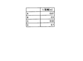
次に、その測距演算結果から、距離分布生成処理を行う(S17−3)。例えば、図18Aのようなシーンにおいては、図18Bのように49のエリアにエリア分割し、図18Cのような距離分布を作成する。表示されている数値は1/距離[m]で表示している。以上のようにして、測距処理を行う。 Next, a distance distribution generation process is performed from the distance measurement calculation result (S17-3). For example, in the scene as shown in FIG. 18A, the area is divided into 49 areas as shown in FIG. 18B, and a distance distribution as shown in FIG. 18C is created. The displayed numerical value is 1 / distance [m]. The distance measurement process is performed as described above.
図12に戻り、タッチパネルがタッチ操作されているかどうかを検知する。タッチパネルのタッチする種類としては、図20のようにa)タップ、b)プレスアンドホールド、c)ドラッグ動作の3種類あるが、本実施例で示す「タッチ」とはc)ドラッグ動作の開始を意味し、タッチ操作されているかどうかを検知しているとは、ドラッグ動作が開始したことを意味する。またデタッチ操作はその逆で、ドラッグ動作を終了しユーザが指を離した時に、「デタッチ」したと検知する。 Returning to FIG. 12, it is detected whether or not the touch panel is touched. As shown in FIG. 20, there are three types of touch on the touch panel: a) tap, b) press and hold, and c) drag operation. The “touch” shown in this embodiment is c) the start of the drag operation. This means that detecting whether or not a touch operation is performed means that a drag operation has started. On the other hand, the detach operation is the opposite, and when the drag operation is finished and the user lifts his / her finger, it is detected as “detached”.
タッチ操作が検知された場合(S12−2でYes)、軌跡保存処理(S12−3)によりそのタッチされている座標をSDRAM(103)に格納する。ユーザがタッチパネル上をドラッグすることで、タッチパネル上での接触点の座標が変化する。その座標を記録することによって、ユーザのドラッグ操作の軌跡を保存することが可能となる。 When the touch operation is detected (Yes in S12-2), the touched coordinates are stored in the SDRAM (103) by the trajectory saving process (S12-3). When the user drags on the touch panel, the coordinates of the contact point on the touch panel change. By recording the coordinates, it is possible to store the locus of the user's drag operation.
その保存された座標をもとにLCDモニタ10にそのドラッグした軌跡を表示させる(S12−4)。例えば、図18Dはその軌跡をLCD表示させたときの状態である。 Based on the stored coordinates, the dragged locus is displayed on the LCD monitor 10 (S12-4). For example, FIG. 18D shows a state when the locus is displayed on the LCD.
デタッチ操作を検知しない間は(S12−5でNo)、上記軌跡保存処理(S12−3)、軌跡表示処理(S12−4)を繰り返す。 While the detach operation is not detected (No in S12-5), the trajectory saving process (S12-3) and the trajectory display process (S12-4) are repeated.
次にデタッチ操作が検知された場合に(S12−5でYes)、上記ドラッグ操作の軌跡から、測距エリアと重なる部分を選択するエリア選択処理に入る(S12−6)。ここでのエリア選択処理は図13のフローチャートのとおりである。 Next, when a detach operation is detected (Yes in S12-5), an area selection process for selecting a portion overlapping the distance measurement area from the drag operation locus is entered (S12-6). The area selection process here is as shown in the flowchart of FIG.
まず、ドラッグされた軌跡に重なる測距エリアを抽出する(S13−1)。例えば、図18Eの測距エリア上に重なるエリアを抽出し、図18Fの状態のような複数のエリアが選択された状態となる。 First, a ranging area that overlaps the dragged locus is extracted (S13-1). For example, an area that overlaps the distance measurement area of FIG. 18E is extracted, and a plurality of areas such as the state of FIG. 18F are selected.
次に、各測距エリアにおいて距離が近いものは同じ被写体であると判定し、エリアを合成する処理(S13−2)を行う。これは測距ユニット5から出力された距離分布より、各測距エリアの1/距離が近いものを抽出し、そのエリアを1つのエリアとして合成する処理である。例えば、図18Gは、この合成をしたときのエリアを示している。つまり、このシーンにおいては、本実施形態のデジタルスチルカメラは、図18Gに示すA〜Eの5つのエリアとその測距結果を持つということになる。各エリアの測距結果は、合成するエリアの平均をとり、その値をその合成エリアの測距演算結果としてSDRAM(103)へ保存しておく。
Next, it is determined that the objects that are close in each distance measurement area are the same subject, and a process of combining the areas (S13-2) is performed. This is a process of extracting the distance measurement areas that are close to 1 / distance from the distance distribution output from the
最後に、合成されたエリアを合焦位置が決定されるフォーカスエリアとして、例えば枠を用いて図18Gの状態の測距エリアを表示する(S13−3)。以上までがエリア選択処理である。 Finally, the synthesized area is used as a focus area where the in-focus position is determined, for example, using a frame to display the distance measurement area in the state of FIG. 18G (S13-3). The above is the area selection process.
図12に戻り、上記エリア選択処理において、上記設定された複数エリアの測距結果を用いて、距離リストを作成する(S12−7)。例えば、図18のシーンに関しては5つのエリアを抽出しているので、その5つのエリアの距離データを抽出する。図18Hはそのときの距離リストである。 Returning to FIG. 12, in the area selection process, a distance list is created using the distance measurement results of the set areas (S12-7). For example, since five areas are extracted for the scene of FIG. 18, distance data of the five areas is extracted. FIG. 18H is a distance list at that time.
距離リストが作成された場合(S12−7)、その距離リストに基づいて高速連続撮影を行う連続撮影処理へと入る(S12−9)。この連続撮影処理は、例えば、LCDモニタ10に表示された撮像画面上に表示させたフォーカスエリアの枠のいずれかがタッチパネルを介してタップまたはタッチされると開始するようにしてもよいし、所定のスイッチ操作に応じて開始するようにしてもよい。
When the distance list is created (S12-7), the process enters a continuous shooting process for performing high-speed continuous shooting based on the distance list (S12-9). This continuous shooting process may be started when, for example, any of the focus area frames displayed on the imaging screen displayed on the
本実施例では、距離リストの距離データから、各フォーカスレンズ7−2aの合焦位置へ変換し、その位置へフォーカスレンズを移動してから撮影することを各距離について順次行う。こうすることで、ユーザが所望とする距離についてのみ、山登りAF動作をせずに、より高速な高速連続撮影をすることが可能となり、撮影での処理時間を削減させることが可能となる。また、露光に関しては、事前にファインダモード時に、測距ユニット5以外のデジタルスチルカメラ内で測光した結果を用いて撮影しても、測距ユニット5での測光結果を用いて撮影しても良いが、高速性を配慮する2次元撮像素子を用いた測距ユニット5からの測光結果を用いたほうが、撮影にかかる処理が速くなる。また、測距ユニット5からの測光結果を用いることで、シャッターチャンスを逃さないという効果を奏する。
In the present embodiment, the distance data in the distance list is converted into the focus position of each focus lens 7-2a, and after the focus lens is moved to that position, shooting is sequentially performed for each distance. By doing so, it is possible to perform high-speed continuous shooting at a high speed without performing a hill-climbing AF operation only at a distance desired by the user, and it is possible to reduce processing time in shooting. In addition, regarding exposure, in the finder mode in advance, shooting may be performed using the result of light metering in a digital still camera other than the
また、特定の測距エリアの合焦位置での高速連続撮影を行えばよいので、ユーザにとって不要な画像が排除され、その結果連続撮影枚数を最適化できる。 In addition, since high-speed continuous shooting at a focus position in a specific distance measurement area may be performed, images unnecessary for the user are eliminated, and as a result, the number of continuous shots can be optimized.
以上、本実施形態のデジタルスチルカメラにおける高速連続撮影処理の第1の実施例について説明した。 The first example of the high-speed continuous shooting process in the digital still camera of the present embodiment has been described above.
(第2の実施例)
続いて、本実施形態のデジタルスチルカメラにおける高速連続撮影処理の第2の実施例について説明する。本実施例のファインダモードから高速連続撮影までの基本的な処理フローは、第1の実施例で図12のフローチャートを用いて説明したとおりである。また、測距ユニット5を使用した測距処理についても、第1の実施例で図15、16、17を用いて説明したとおりである。以下では、ファインダモードから高速連続撮影までの基本的な処理フローに加え、本実施例に特徴的な処理について説明する。
(Second embodiment)
Next, a second example of high-speed continuous shooting processing in the digital still camera of this embodiment will be described. The basic processing flow from the finder mode to high-speed continuous shooting in this embodiment is as described with reference to the flowchart of FIG. 12 in the first embodiment. Further, the distance measuring process using the
まず、デジタルスチルカメラは電源ON後、ファインダモードの状態となる。このファインダモード時に、まず測距ユニット5を使用した測距処理を行う(S12−1)。この測距処理は、第1の実施例において、図15、16、17を用いて前述したとおりであるので、ここではその説明を省略する。この測距処理で、図19Aに示すようなシーンでは、図19Bのように49のエリアにエリア分割し、図19Cに示すような距離分布が作成される。この距離分布に示す数値は、1/距離[m]で表示している。
First, the digital still camera enters the finder mode after the power is turned on. In the finder mode, first, distance measurement processing using the
次いで、タッチパネルがタッチ操作されているかどうかを検知する。タッチパネルに対するタッチとは、本実施例においても、前述のようにドラッグ動作を意味し、タッチ操作されているかどうかを検知しているとは、ドラッグ動作が開始したことを意味する。またデタッチ操作はその逆で、ドラッグ動作を終了しユーザが指を離した時に、「デタッチ」したと検知する。 Next, it is detected whether or not the touch panel is touched. In this embodiment, the touch on the touch panel means a drag operation as described above, and the detection of whether or not a touch operation is performed means that the drag operation has started. On the other hand, the detach operation is the opposite, and when the drag operation is finished and the user lifts his / her finger, it is detected as “detached”.
タッチ操作が検知された場合(S12−2でYes)、軌跡保存処理(S12−3)によりそのタッチされている座標をSDRAM(103)に格納する(S12−3)。つまり、タッチパネル上をドラッグすることでその座標が変化し、その座標を記録することによって、ユーザのドラッグ操作の軌跡を保存することが可能となる。 When the touch operation is detected (Yes in S12-2), the touched coordinates are stored in the SDRAM (103) by the trajectory saving process (S12-3) (S12-3). That is, the coordinates change by dragging on the touch panel, and the coordinates of the user's drag operation can be saved by recording the coordinates.
SDRAM(103)に保存された座標をもとにLCDモニタ10にそのドラッグした軌跡を表示させる(S12−4)。図19Dはその軌跡をLCD表示させたときの状態である。デタッチ操作を検知しない間は(S12−5でNo)、上記軌跡保存処理(S12−3)、軌跡表示処理(S12−4)を繰り返す。 Based on the coordinates stored in the SDRAM (103), the dragged locus is displayed on the LCD monitor 10 (S12-4). FIG. 19D shows a state when the locus is displayed on the LCD. While the detach operation is not detected (No in S12-5), the trajectory saving process (S12-3) and the trajectory display process (S12-4) are repeated.
次にデタッチ操作が検知された場合に(S12−5でYes)、上記ドラッグ操作の軌跡から、測距エリアと重なる部分を選択するエリア選択処理に入る(S12−6)。 Next, when a detach operation is detected (Yes in S12-5), an area selection process for selecting a portion overlapping the distance measurement area from the drag operation locus is entered (S12-6).
ここで、エリア選択処理について、図14のフローチャートを用いて説明する。 Here, the area selection process will be described with reference to the flowchart of FIG.
まず、ドラッグされた軌跡上に顔領域があるかどうかを確認する(S14−1)。顔領域の検知方法に関しては、デジタルスチルカメラの技術分野のおいて様々な手法がすでに知られており、本実施例では、そのうちのいずれかの方法を用いるものとする。以下に、顔領域の検知方法に関する公知例を示す。 First, it is confirmed whether or not there is a face area on the dragged locus (S14-1). Various methods for detecting the face area are already known in the technical field of digital still cameras. In this embodiment, any one of these methods is used. The following is a known example relating to a face area detection method.
(1)テレビジョン学会誌Vol.49、No.6、pp.787−797(1995)の「顔領域抽出に有効な修正HSV表色系の提案」に示されるように、カラー画像をモザイク画像化し、肌色領域に着目して顔領域を抽出する方法。 (1) Television Society Journal Vol. 49, no. 6, pp. No. 787-797 (1995) “Proposal of a modified HSV color system effective for face area extraction” is a method of extracting a face area by converting a color image into a mosaic image and paying attention to a skin color area.
(2)電子情報通信学会誌Vol.74−D−II、No.11、pp.1625−1627(1991)の「静止濃淡情景画像からの顔領域を抽出する手法」に示されているように、髪や目や口など正面人物像の頭部を構成する各部分に関する幾何学的な形状特徴を利用して正面人物の頭部領域を抽出する方法。 (2) Journal of the Institute of Electronics, Information and Communication Engineers, Vol. 74-D-II, no. 11, pp. 1625-1627 (1991) “A method for extracting a face region from a still gray scene image”, the geometrical structure of each part constituting the head of a front human figure such as hair, eyes and mouth. Of extracting the head region of a frontal person using various shape features.
(3)画像ラボ1991−11(1991)の「テレビ電話用顔領域検出とその効果」に示されるように、動画像の場合、フレーム間の人物の微妙な動きによって発生する人物像の輪郭エッジを利用して正面人物像を抽出する方法。 (3) In the case of a moving image, the contour edge of a person image generated by subtle movement of a person between frames, as shown in “Video phone face area detection and its effect” of Image Lab 1991-11 (1991) To extract a frontal portrait using GIS.
上記のような顔領域の検知方法のいずれかの方法を用いて、ファインダモード時のデジタルスチルカメラの画像データを用いて顔検知を行い、顔領域が検知された場合(S14−2でYes)、顔エリアを選択し、その顔エリアと重なる測距エリアを、測距ユニット5から出力される距離分布と比較し、抽出する(S14−3)。
When face detection is performed using image data of a digital still camera in the finder mode by using any one of the face area detection methods as described above (Yes in S14-2). Then, the face area is selected, and the distance measurement area overlapping the face area is compared with the distance distribution output from the
図19Eが、顔エリアが検出できたときの状態である。ここでは4人の顔を検知しており、図19Fに示すようにその顔エリアA〜Dに近い測距エリア部分について、その平均値をそれぞれ算出する。そして、その値を測距演算結果としてSDRAWM(103)へ保存しておく。 FIG. 19E shows a state when a face area has been detected. Here, the faces of four people are detected, and the average values are calculated for the distance measurement area portions close to the face areas A to D as shown in FIG. 19F. Then, the value is stored in the SDRAWM (103) as a distance measurement calculation result.
顔が検出されなかった場合(S14−2でNo)、第1の実施例と同様に、ドラッグされた軌跡に重なる測距エリアを抽出する(S14−5)。測距エリア上に重なるエリアを抽出し、各測距エリアにおいて距離が近いものは同じ被写体であると判定し、エリアを合成する処理(S14−6)を行う。これは、測距ユニット5から出力された距離分布より、各測距エリアの1/距離が近いものを抽出し、そのエリアを1つのエリアとして合成する処理である。各エリアの測距結果は、合成するエリアの距離分布の値の平均をとった上で、その値を測距演算結果としてSDRAM(103)へ保存しておく。
If no face is detected (No in S14-2), a distance measurement area that overlaps the dragged locus is extracted (S14-5), as in the first embodiment. An area that overlaps the distance measurement area is extracted, and it is determined that objects close to each other in the distance measurement area are the same subject, and a process of combining the areas (S14-6) is performed. This is a process of extracting the distance measurement areas that are close to 1 / distance from the distance distribution output from the
最後に、検出されたエリア(または合成されたエリア)を合焦位置が決定されるフォーカスエリアとして、例えば、図19Eに示すように枠を用いて表示する(S14−4)。以上までがエリア選択処理である。 Finally, the detected area (or the combined area) is displayed as a focus area where the in-focus position is determined, for example, using a frame as shown in FIG. 19E (S14-4). The above is the area selection process.
図12に戻り、上記エリア選択処理において、設定された複数エリアの測距結果を用いて、距離リストを作成する(S12−7)。図19のシーンに関しては4つの顔エリアA〜D(図19F)を抽出しているので、その4つのエリアの距離データを抽出する。図19Gはそのときの距離のリストである。 Returning to FIG. 12, in the area selection process, a distance list is created by using the distance measurement results of the plurality of areas that have been set (S12-7). Since the four face areas A to D (FIG. 19F) are extracted with respect to the scene of FIG. 19, distance data of the four areas is extracted. FIG. 19G is a list of distances at that time.
距離のリストが作成されると(S12−7)、その距離リストに基づいて高速連続撮影を行う連続撮影処理へと入る(S12−9)。この連続撮影処理は、例えば、LCDモニタ10に表示された撮像画面上に表示させたフォーカスエリアの枠のいずれかがタッチパネルを介してタップまたはタッチされると開始するようにしてもよいし、所定のスイッチ操作に応じて開始するようにしてもよい。
When a list of distances is created (S12-7), a continuous shooting process for performing high-speed continuous shooting based on the distance list is entered (S12-9). This continuous shooting process may be started when, for example, any of the focus area frames displayed on the imaging screen displayed on the
本実施例においても、第1の実施例と同様に、距離リストの距離データから、各フォーカスレンズ7−2aの合焦位置へ変換し、その位置へフォーカスレンズを移動してから撮影することを各距離について順次行う。こうすることで、ユーザが所望とする距離のみ、山登りAF動作をせずに、より高速な高速連続撮影をすることが可能となり、高速連続撮影での処理時間を削減させることが可能となる。本実施例では特に顔領域を検知しているが、実際のデジタルスチルカメラでは顔優先モードを用意し、顔領域を判別するか、またはそれ以外の被写体も判別するかを切り替えられるようにしておくと尚良い。また、露光に関しては、事前にファインダモード時に、測距ユニット5以外のデジタルスチルカメラ内で測光した結果を用いて撮影しても、測距ユニット5での測光結果を用いて撮影しても良いが、高速性を配慮する2次元撮像素子を用いた測距ユニット5からの測光結果を用いたほうが、撮影にかかる処理が速くなる。また、測距ユニット5からの測光結果を用いることで、シャッターチャンスを逃さないという効果を奏する。
In this embodiment, as in the first embodiment, the distance data in the distance list is converted to the focus position of each focus lens 7-2a, and the focus lens is moved to that position before shooting. Repeat for each distance. By doing so, it is possible to perform high-speed continuous shooting at a high speed without performing a hill-climbing AF operation only for a distance desired by the user, and it is possible to reduce processing time in high-speed continuous shooting. In this embodiment, the face area is particularly detected. However, an actual digital still camera has a face priority mode so that the face area can be discriminated or another subject can be discriminated. And still better. In addition, regarding exposure, in the finder mode in advance, shooting may be performed using the result of light metering in a digital still camera other than the
また、特定の測距エリアの合焦位置での高速連続撮影を行えばよいので、ユーザにとって不要な画像が排除され、その結果連続撮影枚数を最適化できる。 In addition, since high-speed continuous shooting at a focus position in a specific distance measurement area may be performed, images unnecessary for the user are eliminated, and as a result, the number of continuous shots can be optimized.
以上、本実施形態のデジタルスチルカメラにおける高速連続撮影処理の第2の実施例について説明した。 The second example of the high-speed continuous shooting process in the digital still camera of the present embodiment has been described above.
1 サブ液晶ディスプレイ
2 メモリカード装填室および電池装填室の蓋
3 ストロボ発光部
4 光学ファインダ
5 測距ユニット
6 リモコン受光部
7 鏡胴ユニット
8 AF用LED
9 ストロボLED
10 LCDモニタ
13 電源スイッチ
SW1 レリーズスイッチ
SW2 モードダイアル
SW3 広角方向ズームスイッチ
SW4 望遠方向ズームスイッチ
SW5 セルフタイマの設定および解除スイッチ
SW6 メニュースイッチ
SW7 上移動およびストロボセットスイッチ
SW8 右移動スイッチ
SW9 ディスプレイスイッチ
SW10 下移動およびマクロスイッチ
SW11 左移動および画像確認スイッチ
SW12 OKスイッチ
SW13 クイックアクセススイッチ
101 CCD
102 F/E−IC
103 SDRAM
104 デジタルスチルカメラプロセッサ
107 RAM
108 ROM
109 サブCPU(SUB−CPU)
111 LCDドライバ
113 ブザー
117 LCDドライバ
118 ビデオアンプ
119 ビデオジャック
120 内蔵メモリ
121 メモリカードスロット
122 USBコネクタ
DESCRIPTION OF
9 Strobe LED
10 LCD monitor 13 Power switch SW1 Release switch SW2 Mode dial SW3 Wide-angle zoom switch SW4 Tele-zoom switch SW5 Self-timer setting and release switch SW6 Menu switch SW7 Up and strobe set switch SW8 Right switch SW9 Display switch SW10 Down And macro switch SW11 Left shift and image confirmation switch SW12 OK switch SW13
102 F / E-IC
103 SDRAM
104 Digital still
108 ROM
109 Sub CPU (SUB-CPU)
111 LCD Driver 113 Buzzer 117 LCD Driver 118 Video Amplifier 119
Claims (7)
前記撮像手段により撮像した画像を表示する画像表示手段と、
前記画像表示手段の表示面に設置され、前記画像表示手段に表示された画像に対しタッチ操作により複数の位置指定を受け付ける位置指定受付手段と、
複数の2次元撮像素子を用いて被写体までの距離を測距する測距手段と、
前記位置指定受付手段を介して位置指定された複数の範囲を複数の測距エリアとして選択し、選択した複数のエリアのうち前記測距手段から出力される測距結果から算出される距離の差が予め定められた値以下の2以上の測距エリアを合成して1つの測距エリアとして設定する測距エリア設定手段と、
前記測距エリア設定手段で設定された測距エリアの距離に基づき複数の合焦位置を決定する合焦位置決定手段と、
前記合焦位置決定手段により決定された前記複数の合焦位置における複数の画像の撮影を連続して行う連続撮影制御手段と、を備える
ことを特徴とする撮像装置。 Imaging means for converting a subject image into an electrical signal via a lens;
Image display means for displaying an image captured by the imaging means;
A position designation receiving means that is installed on the display surface of the image display means and receives a plurality of position designations by touch operation on the image displayed on the image display means;
Distance measuring means for measuring the distance to the subject using a plurality of two-dimensional image sensors;
A plurality of ranges designated by the position designation accepting means are selected as a plurality of ranging areas, and a distance difference calculated from a ranging result output from the ranging means among the selected plurality of areas. A distance measurement area setting means for combining two or more distance measurement areas with a predetermined value or less to set as one distance measurement area ;
Focusing position determining means for determining a plurality of focusing positions based on distances of the ranging areas set by the ranging area setting means;
An image pickup apparatus comprising: continuous shooting control means for continuously shooting a plurality of images at the plurality of focus positions determined by the focus position determining means.
前記測距エリア設定手段は、測距エリアを設定する際、前記顔領域検出手段により顔領域が検出された場合、検出された顔領域と重なるエリアを設定する
ことを特徴とする請求項1に記載の撮像装置。 A face area detecting means for detecting the face area of the subject;
The distance measurement area setting means sets an area that overlaps the detected face area when the face area detection means detects the face area when setting the distance measurement area. The imaging device described.
測距エリア設定手段として、前記位置指定受付手段を介して位置指定された複数の範囲を複数の測距エリアとして選択し、選択した複数のエリアのうち前記測距手段から出力される測距結果から算出される距離の差が予め定められた値以下の2以上の測距エリアを合成して1つの測距エリアとして設定し、
合焦位置決定手段として、前記測距エリア設定手段で設定された測距エリアの距離に基づき複数の合焦位置を決定し、
連続撮影制御手段として、前記合焦位置決定手段により決定された前記複数の合焦位置における複数の画像の撮影を連続して行う
ことを特徴とする撮像方法。 An image pickup unit that converts a subject image into an electrical signal through a lens, an image display unit that displays an image picked up by the image pickup unit, and a display surface of the image display unit, and is displayed on the image display unit An imaging apparatus comprising: a position designation receiving unit that receives a plurality of position designations by touching an image; and a distance measuring unit that measures a distance to a subject using a plurality of two-dimensional imaging elements. Control means for controlling
As a distance measurement area setting means, a plurality of ranges whose positions are specified via the position specification receiving means are selected as a plurality of distance measurement areas, and a distance measurement result output from the distance measurement means among the selected areas The distance difference calculated from the above is set as one distance measurement area by combining two or more distance measurement areas with a predetermined value or less ,
As the focus position determining means, a plurality of focus positions are determined based on the distance of the distance measurement area set by the distance measurement area setting means,
An imaging method comprising: continuously shooting a plurality of images at the plurality of in-focus positions determined by the in-focus position determining unit as continuous shooting control means.
Priority Applications (6)
| Application Number | Priority Date | Filing Date | Title |
|---|---|---|---|
| JP2011004858A JP5834410B2 (en) | 2011-01-13 | 2011-01-13 | Imaging apparatus and imaging method |
| PCT/JP2012/050657 WO2012096395A1 (en) | 2011-01-13 | 2012-01-10 | Image capturing device and image capturing method |
| US13/978,452 US9106837B2 (en) | 2011-01-13 | 2012-01-10 | Image capturing device and image capturing method |
| EP12734627.8A EP2663889B1 (en) | 2011-01-13 | 2012-01-10 | Image capturing device and image capturing method |
| KR1020137018048A KR101501395B1 (en) | 2011-01-13 | 2012-01-10 | Image capturing device and image capturing method |
| CN201280005164.2A CN103299227B (en) | 2011-01-13 | 2012-01-10 | Image capture device and image-capturing method |
Applications Claiming Priority (1)
| Application Number | Priority Date | Filing Date | Title |
|---|---|---|---|
| JP2011004858A JP5834410B2 (en) | 2011-01-13 | 2011-01-13 | Imaging apparatus and imaging method |
Publications (2)
| Publication Number | Publication Date |
|---|---|
| JP2012145813A JP2012145813A (en) | 2012-08-02 |
| JP5834410B2 true JP5834410B2 (en) | 2015-12-24 |
Family
ID=46507280
Family Applications (1)
| Application Number | Title | Priority Date | Filing Date |
|---|---|---|---|
| JP2011004858A Active JP5834410B2 (en) | 2011-01-13 | 2011-01-13 | Imaging apparatus and imaging method |
Country Status (6)
| Country | Link |
|---|---|
| US (1) | US9106837B2 (en) |
| EP (1) | EP2663889B1 (en) |
| JP (1) | JP5834410B2 (en) |
| KR (1) | KR101501395B1 (en) |
| CN (1) | CN103299227B (en) |
| WO (1) | WO2012096395A1 (en) |
Families Citing this family (15)
| Publication number | Priority date | Publication date | Assignee | Title |
|---|---|---|---|---|
| JP5857610B2 (en) | 2011-10-13 | 2016-02-10 | 株式会社リコー | Imaging apparatus and imaging method |
| KR101838033B1 (en) * | 2011-11-25 | 2018-03-15 | 삼성전자 주식회사 | Method and apparatus for providing image photography of a user device |
| JP6257199B2 (en) * | 2013-07-22 | 2018-01-10 | キヤノン株式会社 | Optical apparatus, control method therefor, and control program |
| JP6212717B2 (en) * | 2014-03-26 | 2017-10-18 | パナソニックIpマネジメント株式会社 | Imaging device |
| US9609200B2 (en) * | 2014-09-24 | 2017-03-28 | Panavision International, L.P. | Distance measurement device for motion picture camera focus applications |
| US9704250B1 (en) | 2014-10-30 | 2017-07-11 | Amazon Technologies, Inc. | Image optimization techniques using depth planes |
| JP6478654B2 (en) | 2015-01-23 | 2019-03-06 | キヤノン株式会社 | Imaging apparatus and control method thereof |
| US9648236B2 (en) * | 2015-02-19 | 2017-05-09 | Blackberry Limited | Device with a front facing camera having discrete focus positions |
| US9800773B2 (en) * | 2015-06-25 | 2017-10-24 | Motorola Mobility Llc | Digital camera apparatus with dynamically customized focus reticle and automatic focus reticle positioning |
| TWI706181B (en) | 2015-09-11 | 2020-10-01 | 新加坡商海特根微光學公司 | Imaging devices having autofocus control |
| KR20180000446U (en) | 2016-08-05 | 2018-02-14 | (주)엠큐어 | Needle Module for Skin Procedure |
| CN108377342B (en) * | 2018-05-22 | 2021-04-20 | Oppo广东移动通信有限公司 | Double-camera shooting method and device, storage medium and terminal |
| JP2020036091A (en) * | 2018-08-27 | 2020-03-05 | キヤノン株式会社 | Imaging device and control method therefor, program, and storage medium |
| JP2020118728A (en) * | 2019-01-18 | 2020-08-06 | オリンパス株式会社 | Focus adjusting device and focus adjusting method |
| JP6768997B1 (en) * | 2019-04-23 | 2020-10-14 | エスゼット ディージェイアイ テクノロジー カンパニー リミテッドSz Dji Technology Co.,Ltd | Control devices, imaging devices, moving objects, control methods, and programs |
Family Cites Families (14)
| Publication number | Priority date | Publication date | Assignee | Title |
|---|---|---|---|---|
| JPH04158322A (en) | 1990-10-23 | 1992-06-01 | Ricoh Co Ltd | Automatic focus adjusting device |
| JPH1125263A (en) * | 1997-07-08 | 1999-01-29 | Canon Inc | Object feature point detector, focus adjusting device, exposure controller and camera |
| JPH11136568A (en) * | 1997-10-31 | 1999-05-21 | Fuji Photo Film Co Ltd | Touch panel operation-type camera |
| JP2001159730A (en) * | 1999-12-02 | 2001-06-12 | Ricoh Co Ltd | Electronic camera |
| JP2004117490A (en) * | 2002-09-24 | 2004-04-15 | Fuji Photo Optical Co Ltd | Autofocus system |
| US8289399B2 (en) * | 2004-08-09 | 2012-10-16 | Hewlett-Packard Development Company, L.P. | System and method for image capture device |
| JP2006138966A (en) * | 2004-11-11 | 2006-06-01 | Nikon Corp | Autofocus camera |
| US20080136958A1 (en) * | 2006-12-11 | 2008-06-12 | Pentax Corporation | Camera having a focus adjusting system and a face recognition function |
| EP2026567B1 (en) | 2007-07-31 | 2010-10-06 | Ricoh Company, Ltd. | Imaging device and imaging method |
| JP4530067B2 (en) | 2008-03-27 | 2010-08-25 | ソニー株式会社 | Imaging apparatus, imaging method, and program |
| JP5169563B2 (en) * | 2008-07-15 | 2013-03-27 | 株式会社ニコン | Focus detection device, camera |
| JP2010085699A (en) * | 2008-09-30 | 2010-04-15 | Fujinon Corp | Auto focus system |
| JP5205232B2 (en) | 2008-11-28 | 2013-06-05 | 三星電子株式会社 | Imaging apparatus and imaging method |
| JP5849389B2 (en) | 2010-11-04 | 2016-01-27 | 株式会社リコー | Imaging apparatus and imaging method |
-
2011
- 2011-01-13 JP JP2011004858A patent/JP5834410B2/en active Active
-
2012
- 2012-01-10 US US13/978,452 patent/US9106837B2/en not_active Expired - Fee Related
- 2012-01-10 KR KR1020137018048A patent/KR101501395B1/en active IP Right Grant
- 2012-01-10 EP EP12734627.8A patent/EP2663889B1/en not_active Not-in-force
- 2012-01-10 WO PCT/JP2012/050657 patent/WO2012096395A1/en active Application Filing
- 2012-01-10 CN CN201280005164.2A patent/CN103299227B/en active Active
Also Published As
| Publication number | Publication date |
|---|---|
| EP2663889B1 (en) | 2017-08-02 |
| EP2663889A4 (en) | 2014-01-22 |
| CN103299227A (en) | 2013-09-11 |
| CN103299227B (en) | 2016-08-10 |
| EP2663889A1 (en) | 2013-11-20 |
| KR20130113495A (en) | 2013-10-15 |
| US20130278809A1 (en) | 2013-10-24 |
| KR101501395B1 (en) | 2015-03-10 |
| WO2012096395A1 (en) | 2012-07-19 |
| US9106837B2 (en) | 2015-08-11 |
| JP2012145813A (en) | 2012-08-02 |
Similar Documents
| Publication | Publication Date | Title |
|---|---|---|
| JP5834410B2 (en) | Imaging apparatus and imaging method | |
| EP2525565B1 (en) | Digital photographing apparatus and method of controlling the same to increase continuous shooting speed for capturing panoramic photographs | |
| US9578260B2 (en) | Digital photographing apparatus and method of controlling the digital photographing apparatus | |
| US8395694B2 (en) | Apparatus and method for blurring image background in digital image processing device | |
| US20150049233A1 (en) | Photographing apparatus and method of controlling the same | |
| US20120105590A1 (en) | Electronic equipment | |
| JP5736796B2 (en) | Electronic camera, program and recording medium | |
| JP4780205B2 (en) | Imaging device, angle of view adjustment method, and program | |
| KR101700366B1 (en) | Digital photographing apparatus and control method thereof | |
| US8648960B2 (en) | Digital photographing apparatus and control method thereof | |
| KR20130069039A (en) | Display apparatus and method and computer-readable storage medium | |
| JP6172428B2 (en) | Imaging apparatus and imaging method | |
| JP2007311861A (en) | Photographic apparatus and method | |
| KR20140096843A (en) | Digital photographing apparatus and control method thereof | |
| JP2011223294A (en) | Imaging apparatus | |
| JP5870533B2 (en) | Imaging apparatus and imaging method | |
| KR20120011920A (en) | Digital image signal processing apparatus, digital image signal processing method and medium for recording the method | |
| JP2007225897A (en) | Focusing position determination device and method | |
| JP2011239267A (en) | Imaging apparatus and image processing apparatus | |
| KR101630302B1 (en) | Digital photographing apparatus and method for controlling the same | |
| JP2011193066A (en) | Image sensing device | |
| KR101635102B1 (en) | Digital photographing apparatus and controlling method thereof | |
| JP5101399B2 (en) | Image capturing apparatus, image capturing apparatus control method, and program | |
| JP2013055540A (en) | Image processor, imaging apparatus and system | |
| JP2014060486A (en) | Image pick-up device |
Legal Events
| Date | Code | Title | Description |
|---|---|---|---|
| A621 | Written request for application examination |
Free format text: JAPANESE INTERMEDIATE CODE: A621 Effective date: 20131202 |
|
| A131 | Notification of reasons for refusal |
Free format text: JAPANESE INTERMEDIATE CODE: A131 Effective date: 20141224 |
|
| A521 | Request for written amendment filed |
Free format text: JAPANESE INTERMEDIATE CODE: A523 Effective date: 20150130 |
|
| A131 | Notification of reasons for refusal |
Free format text: JAPANESE INTERMEDIATE CODE: A131 Effective date: 20150609 |
|
| A521 | Request for written amendment filed |
Free format text: JAPANESE INTERMEDIATE CODE: A523 Effective date: 20150713 |
|
| TRDD | Decision of grant or rejection written | ||
| A01 | Written decision to grant a patent or to grant a registration (utility model) |
Free format text: JAPANESE INTERMEDIATE CODE: A01 Effective date: 20151006 |
|
| A61 | First payment of annual fees (during grant procedure) |
Free format text: JAPANESE INTERMEDIATE CODE: A61 Effective date: 20151019 |
|
| R151 | Written notification of patent or utility model registration |
Ref document number: 5834410 Country of ref document: JP Free format text: JAPANESE INTERMEDIATE CODE: R151 |