JP4780205B2 - Imaging device, angle of view adjustment method, and program - Google Patents
Imaging device, angle of view adjustment method, and program Download PDFInfo
- Publication number
- JP4780205B2 JP4780205B2 JP2009039270A JP2009039270A JP4780205B2 JP 4780205 B2 JP4780205 B2 JP 4780205B2 JP 2009039270 A JP2009039270 A JP 2009039270A JP 2009039270 A JP2009039270 A JP 2009039270A JP 4780205 B2 JP4780205 B2 JP 4780205B2
- Authority
- JP
- Japan
- Prior art keywords
- angle
- image
- imaging
- search point
- unit
- Prior art date
- Legal status (The legal status is an assumption and is not a legal conclusion. Google has not performed a legal analysis and makes no representation as to the accuracy of the status listed.)
- Expired - Fee Related
Links
Images


Classifications
-
- G—PHYSICS
- G06—COMPUTING; CALCULATING OR COUNTING
- G06T—IMAGE DATA PROCESSING OR GENERATION, IN GENERAL
- G06T7/00—Image analysis
- G06T7/20—Analysis of motion
- G06T7/246—Analysis of motion using feature-based methods, e.g. the tracking of corners or segments
-
- H—ELECTRICITY
- H04—ELECTRIC COMMUNICATION TECHNIQUE
- H04N—PICTORIAL COMMUNICATION, e.g. TELEVISION
- H04N23/00—Cameras or camera modules comprising electronic image sensors; Control thereof
- H04N23/60—Control of cameras or camera modules
- H04N23/69—Control of means for changing angle of the field of view, e.g. optical zoom objectives or electronic zooming
-
- G—PHYSICS
- G06—COMPUTING; CALCULATING OR COUNTING
- G06T—IMAGE DATA PROCESSING OR GENERATION, IN GENERAL
- G06T2207/00—Indexing scheme for image analysis or image enhancement
- G06T2207/10—Image acquisition modality
- G06T2207/10016—Video; Image sequence
-
- G—PHYSICS
- G06—COMPUTING; CALCULATING OR COUNTING
- G06T—IMAGE DATA PROCESSING OR GENERATION, IN GENERAL
- G06T2207/00—Indexing scheme for image analysis or image enhancement
- G06T2207/10—Image acquisition modality
- G06T2207/10141—Special mode during image acquisition
- G06T2207/10148—Varying focus
Description
本発明は、撮像装置、画角調節方法、及び、プログラムに関し、詳しくは、被写体を追跡しながら撮影画角を調節してその被写体を所望の大きさで撮影することができる撮像装置、画角調節方法、及び、プログラムに関する。 The present invention relates to an imaging device, an angle-of-view adjustment method, and a program, and more specifically, an imaging device capable of adjusting a shooting angle of view while tracking the subject and shooting the subject with a desired size, and an angle of view. The present invention relates to an adjustment method and a program.
従来より、移動する被写体を最適なサイズで画角に収めて撮影したいという要望がある。そして、そのような要望を満たすための技術として、例えば、下記の特許文献1に記載する、動きを伴う被写体をテンプレートマッチング法により継続的に検出して追跡し、その被写体のサイズの変化に合わせてズーム倍率を自動制御する技術を採用することで、撮影者はズーム操作を行うこと無しに、移動する被写体を最適なサイズで撮影することができる。
Conventionally, there has been a demand for photographing a moving subject with an optimum size within an angle of view. As a technique for satisfying such a demand, for example, a subject with motion described in
しかしながら、上記の特許文献1に記載されるテンプレートマッチング法は、「追跡する被写体のサイズや形状が大きくは変化しない」という前提が成立してこそ可能となる。
したがって、移動するとともにサイズや形状を変えてゆく被写体を追跡するケース、より具体的には、ランナーが遠方から近づき、撮影者の直前を横切り、そして、遠方へ去っていくようなケースでは、マッチングに利用するテンプレートを逐次変更する必要があり、処理量が増えるという問題があった。
However, the template matching method described in
Therefore, when tracking a subject that moves and changes size and shape, more specifically, when a runner approaches from a distance, crosses in front of the photographer, and then moves away. There is a problem in that the amount of processing increases because it is necessary to sequentially change the template used in the process.
そこで、本発明の目的は、被写体のサイズが大きく変化する場合でも、追跡のための処理量に負担をかけることなく、被写体を追跡して最適なサイズで撮影することができるようにすることにある。 Accordingly, an object of the present invention is to enable tracking of a subject and shooting at an optimum size without imposing a burden on the processing amount for tracking even when the size of the subject changes greatly. is there.
請求項1に記載の発明は、撮像手段と、この撮像手段によって撮像される画像に含まれる、追跡すべき画像領域を指定する指定手段と、前記撮像手段に対し順次撮像するよう制御する撮像制御手段と、前記指定手段によって指定された画像領域の特徴量を記憶する記憶手段と、前記画像領域に複数の探索点を設定する探索点設定手段と、乱数を用いて前記探索点設定手段によって設定された探索点の座標を更新する更新手段と、前記記憶手段に記憶されている特徴量と前記更新手段によって更新された探索点の特徴量とを比較して類似度に応じた重みを各探索点に設定する重み設定手段と、この重み設定手段によって重みが設定された探索点を、前記重みに応じて選別する選別手段と、この選別手段によって選別された探索点の分散を取得する分散取得手段と、この分散取得手段によって取得された分散の変化に応じて、前記撮像制御手段によって順次撮像される画像間の変化の傾向を判断する判断手段と、この判断手段によって判断された変化の傾向に応じて、前記画像領域を含む撮影画角を調節する画角調節手段と、を備えることを特徴とする撮像装置である。
請求項2に記載の発明は、前記分散取得手段によって取得された分散に応じて、前記画角調節手段によって、前記画角調節手段が調節するべき調節量を取得する調節量取得手段を更に備えることを特徴とする請求項1記載の撮像装置である。
請求項3に記載の発明は、前記画角調節手段は、前記判断手段によって分散が小さくなったと判断された場合は撮影画角を狭くし、前記判断手段によって分散が大きくなったと判断された場合は撮影画角を広くするように撮影画角を調節することを特徴とする請求項1又は2記載の撮像装置である。
請求項4記載の発明は、前記画角調節手段は、前記撮像制御手段によって順次撮像される画像間で前記画像領域が略一定の大きさになるように画角を調節することを特徴とする請求項1〜3の何れかに記載の撮像装置である。
請求項5記載の発明は、ズームレンズを備え、前記画角調節手段は、このズームレンズを駆動させることにより前記撮影画角を調節することを特徴とする請求項1〜4の何れかに記載の撮像装置である。
請求項6記載の発明は、フォーカスレンズを駆動することにより被写体に合焦する合焦手段を更に備え、前記指定手段が指定する画像領域とは、前記画像中における前記合焦手段によって合焦した領域であることを特徴とする請求項1〜5の何れかに記載の撮像装置である。
請求項7に記載の発明は、撮像部にて撮像される画像に含まれる、追跡すべき画像領域を指定する指定ステップと、前記撮像部に対し順次撮像するよう制御する撮像制御ステップと、前記指定ステップによって指定された画像領域の特徴量を記憶する記憶ステップと、前記画像領域に複数の探索点を設定する探索点設定ステップと、乱数を用いて前記探索点設定ステップによって設定された探索点の座標を更新する更新ステップと、前記記憶ステップに記憶されている特徴量と前記更新ステップによって更新された探索点の特徴量とを比較して類似度に応じた重みを各探索点に設定する重み設定ステップと、この重み設定ステップによって重みが設定された探索点を、前記重みに応じて選別する選別ステップと、この選別ステップによって選別された探索点の分散を取得する分散取得ステップと、この分散取得ステップによって取得された分散の変化に応じて、前記撮像制御ステップによって順次撮像される画像間の変化の傾向を判断する判断ステップと、この判断ステップにて判断された変化の傾向に応じて、前記画像領域を含む撮影画角を調節する画角調節ステップと、を含むことを特徴とする画角調節方法である。
請求項8に記載の発明は、撮像装置が有するコンピュータを、撮像される画像に含まれる、追跡すべき画像領域を指定する指定手段、順次撮像するよう制御する撮像制御手段、前記指定手段によって指定された画像領域の特徴量を記憶する記憶手段、前記画像領域に複数の探索点を設定する探索点設定手段、乱数を用いて前記探索点設定手段によって設定された探索点の座標を更新する更新手段、前記記憶手段に記憶されている特徴量と前記更新手段によって更新された探索点の特徴量とを比較して類似度に応じた重みを各探索点に設定する重み設定手段、この重み設定手段によって重みが設定された探索点を、前記重みに応じて選別する選別手段、この選別手段によって選別された探索点の分散を取得する分散取得手段、この分散取得手段によって取得された分散の変化に応じて、前記撮像制御手段によって順次撮像される画像間の変化の傾向を判断する判断手段、この判断手段によって判断された変化の傾向に応じて、前記画像領域を含む撮影画角を調節する画角調節手段、として機能させることを特徴とするプログラムである。
According to the first aspect of the present invention, an imaging unit, a designation unit for designating an image area to be tracked included in an image captured by the imaging unit, and an imaging control for controlling the imaging unit to sequentially capture images. Means for storing the feature quantity of the image area designated by the designation means, search point setting means for setting a plurality of search points in the image area, and setting by the search point setting means using random numbers Updating means for updating the coordinates of the searched search points, comparing the feature quantities stored in the storage means with the feature quantities of the search points updated by the update means, and calculating a weight corresponding to the degree of similarity for each search A weight setting means for setting a point; a selection means for selecting a search point set with a weight by the weight setting means according to the weight; and a variance of the search points selected by the selection means. A dispersion obtaining means, according to the change of the acquired dispersed by the dispersion obtaining means, determination means for determining the trend of the change between images sequentially captured by the imaging control means, change is determined by the determining means And an angle-of-view adjusting unit that adjusts the angle of view including the image area according to the tendency.
The invention according to
According to a third aspect of the present invention, when the angle of view adjustment means determines that the variance has been reduced by the determination means, the imaging angle of view is narrowed, and when the determination means has determined that the variance has increased. The imaging apparatus according to
According to a fourth aspect of the present invention, the angle-of-view adjusting unit adjusts the angle of view so that the image area has a substantially constant size between images sequentially captured by the imaging control unit. It is an imaging device in any one of Claims 1-3 .
Invention of
The invention according to
The invention according to
According to the eighth aspect of the present invention, the computer included in the image pickup apparatus is designated by the designation means for designating the image area to be tracked included in the image to be picked up, the image pickup control means for controlling to sequentially pick up images, and the designation means. Storage means for storing the feature amount of the image area, search point setting means for setting a plurality of search points in the image area, and updating for updating the coordinates of the search points set by the search point setting means using random numbers Means, weight setting means for comparing the feature quantity stored in the storage means with the feature quantity of the search point updated by the update means, and setting a weight corresponding to the similarity to each search point, the weight setting Sorting means for sorting search points for which weights are set by the means according to the weights, dispersion obtaining means for obtaining the variance of the search points sorted by the sorting means, and the dispersion obtaining means Thus in accordance with the change of the acquired dispersed, determining means for determining the trend of change between images sequentially captured by the imaging control means, in accordance with the trend of the changes is determined by the determining means, the image area A program that functions as an angle-of-view adjusting unit that adjusts a shooting angle of view.
本発明によれば、被写体のサイズが大きく変化する場合でも、追跡のための処理量に負担をかけることなく、被写体を追跡して最適なサイズで撮影することができる。 According to the present invention, even when the size of the subject changes greatly, the subject can be tracked and photographed at the optimum size without imposing a burden on the processing amount for tracking.
以下、本発明の実施形態を、デジタルカメラを例にして、図面を参照しながら説明する。
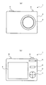
図1は、デジタルカメラ1の外観図であり、(a)は前面図、(b)は背面図である。この図において、デジタルカメラ1は、手持ちに適した形状のボディ2の前面に電動ズーム機能を内蔵したレンズ鏡筒3を配すると共に、そのボディ2の背面に液晶ディスプレイからなる表示部4、ズームキー5、ファンクションキー6及びカーソルキー7を配し、さらに、そのボディ2の上面に電源スイッチ8やハーフシャッタ機能付きのシャッタキー9を配して構成されている。なお、この構成は汎用デジタルカメラのものであるが、これに限定されず、たとえば、デジタル一眼レフカメラのような構成であっても構わないし、あるいは、携帯電話機やその他の電子機器に搭載されたもの、または、デジタルビデオカメラに搭載されたものであってもよい。
Hereinafter, embodiments of the present invention will be described with reference to the drawings, taking a digital camera as an example.
1A and 1B are external views of the
図2は、デジタルカメラ1の概略構成を示すブロック図である。この図において、デジタルカメラ1は、レンズ鏡筒3、ズーム駆動制御部10、フォーカス駆動制御部11、撮像部12、CDS/ADC13、画像処理部14、符号化/復号化処理部15、プレビューエンジン16、キー入力部17、表示部4、中央制御部18、RAM19、プログラムメモリ20、画像記録部21、追跡処理部22及びこれらの各部を接続するバスライン23を含む。
FIG. 2 is a block diagram illustrating a schematic configuration of the
各部の詳細を説明すると、まず、レンズ鏡筒3は、光軸が揃えられた複数枚の撮影レンズを収めたレンズユニットであり、図示の撮影レンズは、そのうちのズームレンズ3aとフォーカスレンズ3bを示している。ズームレンズ3aは、ズーム駆動制御部10の制御によって動作する不図示のズームモータの動きに伴い、他の撮影レンズに対して光軸上を前後に移動可能になっており、この移動により、被写体24に対する撮影レンズの撮影画角(ズーム倍率)を調整する。また、フォーカスレンズ3bは、フォーカス駆動制御部11の制御によって動作する不図示のフォーカスモータの動きに伴い、他の撮影レンズに対して光軸上を前後に移動可能になっており、この移動により、被写体24の焦点位置を調整する。
The details of each part will be described. First, the
撮像部12は、CCDやCMOSなどの二次元イメージセンサで構成されており、上述のズームレンズ3aやフォーカスレンズ3bを含む撮影レンズの光軸上に配置され、この撮影レンズを介して結像する被写体の光学像に応じたアナログの撮像信号を出力する。
The
CDS/ADC13は、撮像部12から出力される被写体の光学像に応じたアナログの撮像信号をデジタル信号に変換する回路であり、このCDS/ADC13は、入力された撮像信号を保持するCDSと、AE(自動露出調整)処理等に伴って撮像信号を増幅するゲイン調整アンプ(AGC)、増幅された撮像信号をデジタルの撮像信号に変換するA/D変換器(ADC)等から構成されている。
The CDS /
画像処理部14は、CDS/ADC13から出力されたデジタルの撮像信号に対して各種の画像処理(ガンマ処理等)を施す回路である。
The
符号化/復号化処理部15は、JPEG形式等の所定の符号化方式で記録画像(画像記録部21に書き込まれる画像ファイル)を圧縮したり、また、同方式で再生画像(画像記録部21から読み出される画像ファイル)を伸張したりする回路である。
The encoding /
プレビューエンジン16は、CDS/ADC13から出力されたデジタルの撮像信号を縮小加工し、構図確認用のスルー画像(またはプレビュー画像ともいう。)として表示部4に出力したり、また、画像記録モードにおいて画像記録部21に記録される直前の画像を縮小加工して表示部4に出力したり、さらには、画像再生モードにおいて画像記録部21から読み出された画像を縮小加工して表示部4に出力したりする回路である。
The
キー入力部17は、ボディ2の各部に配置された各種ボタン類(ズームキー5、ファンクションキー6、カーソルキー7、シャッタキー9等)の操作信号を生成する回路である。
The
表示部4は、所定アスペクト比(たとえば、16:9)の液晶ディスプレイとドライバからなり、表示信号やドライバを駆動する駆動制御信号が入力されると、その表示信号に基づく画像をスルー画像として下位レイヤーに表示し、また、中央制御部18から出力されるメッセージやアイコンなどを上位レイヤーに表示する。
The
中央制御部18は、デジタルカメラ1の各部を統括制御するワンチップマイクロコンピュータであり、この中央制御部18は、予めプログラムメモリ15に格納されている制御プログラムを読み出し、この制御プログラムを実行することによってデジタルカメラ1の各部を制御し、撮像信号に含まれる輝度情報に基づいたAE制御処理や、コントラスト検出方式によるオートフォーカス(AF)制御処理、ズーム制御、及び、後述の記録モード処理などを行う。
The
RAM19は、CDS/ADC13から出力される画像信号を一時的に記憶するバッファメモリであり、このバッファメモリは連続撮影された画像を複数枚記憶できる容量を持っている。
The
プログラムメモリ20は、中央制御部18で実行される制御プログラムを予め格納保持するものであり、画像記録部21は、撮影済みの画像ファイルを記録保存するものである。この画像記録部21は、たとえば、メモリカードのような着脱できるものであってもよい。
The
追跡処理部22は、後述の追跡処理を実行する回路である。バスライン23は、デジタルカメラ1の各部の信号伝達を行う共通線である。
The
次に、デジタルカメラ1の動作について説明する。
「撮影シーンの例」
図3は、本実施形態における撮影シーンの一例を示す概念図である。(a)は被写体24とデジタルカメラ1の位置関係例であり、上からの俯瞰図である。この例では、被写体24が遠方(図面に正対して右方)からデジタルカメラ1に向かって接近し、デジタルカメラ1の前を通り越し、再び遠ざかる際の時系列的な位置関係を示している。(b)は、その際におけるデジタルカメラ1のファインダ画像(表示部4に写し出されているスルー画像)を示しており、画像25は被写体24が遠方からデジタルカメラ1に向かいつつあるとき、画像26は被写体24がデジタルカメラ1の前を通り過ぎる瞬間、画像27は被写体24がデジタルカメラ1に対して背を見せながら遠ざかるときのものである。
Next, the operation of the
“Examples of shooting scenes”
FIG. 3 is a conceptual diagram illustrating an example of a shooting scene in the present embodiment. (A) is an example of the positional relationship between the subject 24 and the
このような撮影シーンにおいては、画像25、26、27に示すように、被写体24が「小」から「大」、そして、再び「小」へと変化するので、撮影者は、ズームキー5を操作しながら、被写体24が所望の大きさになるように設定し、任意のシャッタチャンスを待ってシャッタキー9を全押しするものの、継続的なズーム操作は面倒を否めない。そこで、本実施形態では、最初に一度だけズーム操作を行って画角を設定し、被写体24の大きさを意図したものにした後は、以降、自動的に画角を調節できるようにして、上記の不都合(面倒)を回避する。
In such a shooting scene, as shown in the
具体的には、画像25の被写体24が構図一杯に入るように手動でズームアップすると、それ以降の画像26や画像27の被写体24の大きさが、手動ズームアップ時の大きさに合わせて自動的に加減されるようにし、これにより、上記の不都合(面倒)を回避する。
Specifically, when manually zooming up so that the subject 24 of the
(c)は、そのようにして設定された画像25´〜27´を示している。画像25´の被写体24は手動でズームアップされたもの、それ以降の画像26´、27´の被写体24は自動的に大きさが加減されたものである。
(C) shows the
この(c)に示すように、本実施形態では、大きさが変化しつつ移動する被写体24に対して、自動的に画角(ズーム倍率)を調節して、その被写体24の大きさをほぼ一定に維持できるので、操作の面倒さを招くことなくいつでも所望の画角でシャッターを切ることができるという効果が得られる上、さらに、後でも詳しく説明するが、冒頭の特許文献1のようにテンプレートマッチング法も用いないので、この特許文献1の欠点(処理時間の増加)を招かないという特有の効果が得られる。
As shown in (c), in the present embodiment, the angle of view (zoom magnification) is automatically adjusted for the subject 24 that moves while changing its size, so that the size of the subject 24 is substantially reduced. Since it can be maintained constant, the effect that the shutter can be released at a desired angle of view at any time without incurring troublesome operation is obtained, and further detailed description will be given later, as in
図4は、自動ズームを行わない場合と行った場合のスルー画像対比図である。(a)は自動ズームを行わない場合の画像25、26、27を示しており、画像25には遠方の被写体24、画像26にはデジタルカメラ1の前を通り過ぎる瞬間の被写体24、画像27には背を見せながら遠ざかる被写体24が写っている。これらの画像25、26、27において、自動ズームを行わない場合の被写体24の大きさは「小」から「大」へと変化し、さらに再び「小」へと変化する経過を辿る。ここで、説明の便宜上、画像25に写っている被写体24の大きさをa、画像26に写っている被写体24の大きさをb、画像27に写っている被写体24の大きさをcとし、a<b>cであるものとする。
FIG. 4 is a through-image comparison diagram when the automatic zoom is not performed and when the automatic zoom is performed. (A) shows
本実施形態における意図は、(a)のように大きさが変化(a→b→c)する被写体24を、(b)に示すように一定の大きさ(A=B=C)に維持することにある。 The intention in the present embodiment is to maintain the subject 24 whose size changes (a → b → c) as shown in (a) at a constant size (A = B = C) as shown in (b). There is.
一定の大きさの目標は、多くの場合、ファインダからはみ出さない程度で且つできるだけファインダ一杯に入る大きさである。これは、たとえば、被写体24をマラソンランナーとしたときに、そのランナーの表情と全身を構図一杯に捉えて撮影するという一般的要求に合致する。とりわけ、マラソンランナーのような動きの速い被写体24を撮影する場合は、その速度感を表現するために背景を流して撮影する、いわゆる“流し撮り”のテクニックが用いられることが多く、このような場合、被写体24をできるだけ大きく撮影する(引きで撮影する)ことが求められるから、前記の目標(ファインダからはみ出さない程度で且つできるだけファインダ一杯に入る大きさ)は合理的である。
The fixed size target is often large enough not to stick out of the viewfinder and fill the viewfinder as much as possible. For example, when the subject 24 is a marathon runner, it meets the general requirement to capture the runner's facial expression and whole body in full composition. In particular, when shooting a fast-moving
かかる目標を得るために、本実施形態では、一度だけ手動によるズーム操作を行う。つまり、撮影者は、画像25の段階でズームキー5を操作し、その画像25に写し込まれている被写体24の大きさcを目標の大きさ(画像25´に写し込まれている被写体24の大きさA)に合わせ込む。
In order to obtain such a target, in this embodiment, a manual zoom operation is performed only once. That is, the photographer operates the
以降、本実施形態においては、画像26に写し込まれている被写体24の大きさbが目標の大きさ(画像26´に写し込まれている被写体24の大きさB)になるように自動ズームを行い、さらに、画像27に写し込まれている被写体24の大きさcが目標の大きさ(画像27´に写し込まれている被写体24の大きさC)になるように自動ズームを行うことにより、結局、その間のスルー画像(画像25´〜画像27´)に写し込まれている被写体24の大きさを、目標の大きさに合わせて一定に維持(A=B=C)することができるのである。
Thereafter, in this embodiment, automatic zooming is performed so that the size b of the subject 24 imprinted on the
次に、本実施形態の制御プログラムについて説明する。
[記録モード処理]
図5は、記録モード処理を実行するための制御プログラムのフローを示す図である。記録モード処理とは、構図確認のためのスルー画像を表示部4に表示しながら、撮影者によるハーフシャッタ操作(シャッタキー9の半押し操作)を検出すると、AE(自動露出調整)やAWB(自動ホワイトバランス調整)及びAF(オートフォーカス)を行い、さらに、撮影者によるフルシャッタ操作(シャッタキー9の全押し操作)を検出すると、その時点の撮影画像をJPEGファイルに変換して画像記録部21に記録保存するという一連の処理のことである。
Next, the control program of this embodiment will be described.
[Recording mode processing]
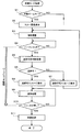
FIG. 5 is a diagram showing a flow of a control program for executing the recording mode process. In the recording mode process, if a photographer detects a half-shutter operation (half-press operation of the shutter key 9) while displaying a through image for composition confirmation on the
この制御プログラムは、予めプログラムメモリ20に格納されたものであり、画像記録モードにおいて、中央制御部18にて実行されるものである。
This control program is stored in advance in the
記録モード処理を開始すると、中央制御部18は、まず、自動ズームモードであるか否かを判定する(ステップS1)。自動ズームモードとは、大きさが変化しつつ移動する被写体24に対して、自動的に画角(ズーム倍率)を調節して、その被写体24の大きさをほぼ一定に維持する際に用いられるモードのことである。ステップS1の判定結果がNOの場合は、他の撮影モード(自動ズームを用いない通常の記録モード等)であると判断し、その撮影モードを実行するための処理(図示略)に分岐するが、ステップS1の判定結果がYESの場合は、以下の処理を実行する。
When the recording mode process is started, the
まず、表示部4にスルー画像を表示すると(ステップS2)、撮影者はズームキー5を操作して、被写体が表示領域中で所望の大きさになるように画角を調整する(ステップS3)。
First, when a through image is displayed on the display unit 4 (step S2), the photographer operates the
画角の調整を終えると、次に、中央制御部18は、ハーフシャッタ(シャッタキー9の半押し操作)の検出を待ち(ステップS4)、ハーフシャッタの操作を検出すると、AE(自動露出調整)やAWB(自動ホワイトバランス調整)及びAF(オートフォーカス)を行うとともに、後で詳しく説明する「追跡可否判断処理」(ステップS5)を実行し、その判断結果が「追跡可」であるか否かを判定する(ステップS6)。「追跡可否判断処理」とは、簡単に言えば、ハーフシャッタによってAFが行われた画像領域を追跡すべき画像領域(後述の評価対象画像)として指定し、その画像領域に含まれる被写体の動きを追跡できるか否かを判断する処理のことである。
When the adjustment of the angle of view is finished, the
ステップS4で追跡不可と判断された場合は、表示部4に追跡不可メッセージを表示(ステップS7)して再び画角調整(ステップS3)に戻り、追跡可と判断された場合は、表示部4に追跡可メッセージを表示(ステップS8)した後、後で詳しく説明する「追跡処理」(ステップS9)を実行しながら、シャッタキー5の全押し操作を待つ(ステップS10)。「追跡処理」とは、簡単に言えば、ハーフシャッタによってAFが行われた被写体の動きを追跡しつつ、その被写体が一定の大きさ(前記の目標の大きさ)になるように継続的に自動ズームを行う一連の処理のことをいう。
If it is determined in step S4 that tracking is not possible, a tracking impossible message is displayed on the display unit 4 (step S7), and the process returns to angle of view adjustment (step S3). If it is determined that tracking is possible, the
ステップS4のハーフシャッタ検出から、このステップS9の追跡処理が完了するまでの間、撮影者によるハーフシャッタ操作は継続している。なお、その間において、撮影者によるハーフシャッタ操作が中断された場合、すなわち、シャッタキー9から指先が離れた場合は、撮影中止であるので、図示のフローでは省略しているが、その時点でフローから抜け、制御プログラムを途中終了する。 The half-shutter operation by the photographer continues from the half-shutter detection in step S4 until the tracking process in step S9 is completed. In the meantime, when the half-shutter operation by the photographer is interrupted, that is, when the fingertip is released from the shutter key 9, the photographing is stopped and is omitted in the illustrated flow, but the flow at that time Exit from the control program.
「追跡処理」を行っている間に、シャッタキー9の全押し操作を検出すると、その時点で撮像部12から出力される高精細な画像信号をJPEG形式の画像ファイルに変換し、その画像ファイルを画像記録部21に記録保存(ステップS11)した後、プログラムを終了する。
When a full press of the shutter key 9 is detected during the “tracking process”, a high-definition image signal output from the
[追跡可否判断処理]
図6は、追跡可否判断処理(図5のステップS5参照)を中央制御部18で実行するための制御プログラムのフローを示す図である。このフローでは、スルー画像から上記のAFAFが行われた画像領域n枚(ここではn=5)を評価対象画像として取得し(ステップS110)、この5枚の評価対象画像に対して以下の学習処理を順番に行う。
[Traceability determination processing]
FIG. 6 is a diagram showing a flow of a control program for causing the
まず、評価対象画像に所定数の探索点(以下、粒子という)Pを生成する(ステップS111)。たとえば、粒子Pの個数を256個とすると、各々の粒子Pの座標は、P[num](Px[num],Py[num])(0<=num<=255)と表される。 First, a predetermined number of search points (hereinafter referred to as particles) P are generated in the evaluation target image (step S111). For example, if the number of particles P is 256, the coordinates of each particle P are expressed as P [num] (Px [num], Py [num]) (0 <= num <= 255).
なお、本実施形態では、粒子Pの個数を256個としたが、これに限らず、適切な個数は、デジタルカメラ1に搭載されるCPUの処理能力に基づいて適宜決定すればよい。
In the present embodiment, the number of particles P is 256. However, the number is not limited to this, and an appropriate number may be appropriately determined based on the processing capability of the CPU mounted on the
次いで、各粒子P[num]を中心とする所定範囲を、探索対象領域T[num]として設定する(ステップS112)。 Next, a predetermined range centered on each particle P [num] is set as a search target region T [num] (step S112).
図7(a)は、探索対象領域T[num]の概念図である。この図に示すように、size=2とし、探索対象領域Tを各粒子から縦横2画素範囲、つまり各粒子を中心とした縦5画素、横5画素の範囲とする。この探索対象領域T[num]は、次式(1)で表される。 FIG. 7A is a conceptual diagram of the search target region T [num]. As shown in the figure, size = 2 is set, and the search target region T is set to a range of 2 pixels in the vertical and horizontal directions from each particle, that is, a range of 5 pixels in the vertical direction and 5 pixels in the horizontal direction centering on each particle. This search target area T [num] is expressed by the following equation (1).

なお、本実施形態では、説明の容易化のためにsize=2としたが、これに限らない。適切なsizeの値は学習精度と処理負担のトレードオフから決定すべきであり、実用上の観点からは、たとえば、4<size<10程度に設定することが望ましい。 In the present embodiment, size = 2 is set for ease of explanation, but the present invention is not limited to this. An appropriate size value should be determined based on a trade-off between learning accuracy and processing load. From a practical viewpoint, for example, it is desirable to set the size to about 4 <size <10.
次いで、全ての粒子P[num]の初期座標を設定する(ステップS113)。
図7(b)は、初期座標設定の概念図である。この図に示すように、オートフォーカスエリアEの内側に追跡対象領域Cを設定すると共に、その追跡対象領域Cの中心点を粒子Pの初期座標(Fx,Fy)とし、1枚目の評価対象画像のYUVの各色空間(Y色空間:Sr1、U色空間:Sr2、V色空間:Sr3)において、それぞれの追跡対象領域Cの基準画素値B1、B2、B3を記憶する(ステップS114)。
Next, initial coordinates of all particles P [num] are set (step S113).
FIG. 7B is a conceptual diagram of initial coordinate setting. As shown in this figure, the tracking target area C is set inside the autofocus area E, and the central point of the tracking target area C is set as the initial coordinates (Fx, Fy) of the particle P, and the first evaluation object In each YUV color space (Y color space: Sr1, U color space: Sr2, V color space: Sr3) of the image, the reference pixel values B1, B2, B3 of the respective tracking target areas C are stored (step S114).
このように、フォーカスエリアEの中心の座標を(Fx,Fy)とすると、粒子P[num]の初期座標は、次式(2)のように表される。 As described above, when the coordinates of the center of the focus area E are (Fx, Fy), the initial coordinates of the particle P [num] are expressed by the following equation (2).
なお、本実施形態では、評価対象画像の色空間としてYUV色空間を用いたが、これに限らず、RGB色空間、HSV色空間、HLS色空間、OHHTA色空間など他の色空間を用いてもよいことはもちろんである。デジタルカメラ1のスルー画像の色空間に応じて適宜選択すればよい。
In this embodiment, the YUV color space is used as the color space of the evaluation target image. However, the present invention is not limited to this, and other color spaces such as the RGB color space, HSV color space, HLS color space, and OHHTA color space are used. Of course it is good. What is necessary is just to select suitably according to the color space of the through image of the
評価対象画像のY色空間をSr1、U色空間をSr2、V色空間をSr3としたときの、それぞれの基準画素値B1、B2、B3は、次式(3)〜(5)で表される。 The reference pixel values B1, B2, and B3 when the Y color space of the evaluation target image is Sr1, the U color space is Sr2, and the V color space is Sr3 are expressed by the following equations (3) to (5). The
次いで、点線で囲んだ5つの処理(ステップS115〜ステップS119)を実行するが、この5つの処理と同様の処理は、後述の「追跡処理」(図12参照)にも含まれている。 Next, five processes (steps S115 to S119) surrounded by a dotted line are executed. The same processes as these five processes are also included in a “tracking process” (see FIG. 12) described later.
この5つの処理を説明すると、まず、正規分布に従う乱数を用いて、全ての粒子P[num]の座標を更新する(ステップS115)。 Explaining these five processes, first, the coordinates of all the particles P [num] are updated using random numbers according to a normal distribution (step S115).
図8は、粒子Pの分布を示す図である。なお、この図では、簡単化のために256個の粒子Pのうちの20個のみを示している。図において、正方形の升目はそれぞれ探索対象領域Tであり、一部探索対象領域にT[0]、T[1]、T[2]、T[3]、T[4]・・・・T[6]の符号を付してある。また、升目内のドットはそれぞれ粒子Pであり、同様に、それらの粒子PにP[0]、P[1]、P[2]、P[3]、P[4]・・・・P[6]の符号を付してある。 FIG. 8 is a diagram showing the distribution of particles P. As shown in FIG. In this figure, only 20 of the 256 particles P are shown for simplicity. In the figure, each square cell is a search target region T, and T [0], T [1], T [2], T [3], T [4]. Reference numeral [6] is attached. In addition, each dot in the mesh is a particle P. Similarly, P [0], P [1], P [2], P [3], P [4],. Reference numeral [6] is attached.
ここで、平均μ、分散σ2の正規分布に従う乱数をN(μ,σ2)とした場合、粒子P[num]の座標は、次式(6)のように更新される。 Here, when a random number according to a normal distribution with an average μ and a variance σ2 is N (μ, σ2), the coordinates of the particle P [num] are updated as in the following equation (6).
このようにして、全ての粒子P[num]の座標を更新すると、次に、各粒子の重みを算出する(ステップS116)。具体的には、評価対象画像のYUVの各色空間において、それぞれの探索対象領域T[num]を構成する画素Qの画素値を算出し、その画素値と記憶した基準画素値B1〜B3との差分が所定範囲内であるものの画素数を計数して、その個数を当該粒子の重みとする。 When the coordinates of all the particles P [num] are updated in this way, the weight of each particle is then calculated (step S116). Specifically, in each YUV color space of the evaluation target image, the pixel value of the pixel Q constituting each search target region T [num] is calculated, and the pixel value and the stored reference pixel values B1 to B3 are calculated. The number of pixels whose difference is within a predetermined range is counted, and the number is set as the weight of the particle.
この「重み」は、評価対象画像の探索対象領域T[num]と1枚目の評価対象画像の追跡対象領域Cとの類似度合いを示す。すなわち、重みが大きいということは、評価対象画像の探索領域T[num]と、1枚目の評価対象画像の追跡対象領域Cとが類似していることを意味する。 This “weight” indicates the degree of similarity between the search target area T [num] of the evaluation target image and the tracking target area C of the first evaluation target image. That is, a large weight means that the search area T [num] of the evaluation target image is similar to the tracking target area C of the first evaluation target image.
具体的には、上下の閾値をTH1,TH2として、次式(7)〜(9)を満たすものの画素Qの個数をカウントし、重みPw[num]とする。ちなみに、本実施形態では、sizeを2とし、各探索対象領域T[num]を構成する画素Qを25個としたので、重みPw[num]の最小値はゼロ、最大値は25となる。 Specifically, the upper and lower threshold values are TH1 and TH2, and the number of pixels Q that satisfy the following equations (7) to (9) is counted to obtain a weight Pw [num]. Incidentally, in this embodiment, since the size is 2 and the number of pixels Q constituting each search target region T [num] is 25, the minimum value of the weight Pw [num] is zero and the maximum value is 25.
次に、粒子Pのリサンプリングを行う(ステップS117)。具体的には、閾値をTH3として、重みPwがTH3以下である粒子を除去した後、粒子Pのサンプリングを行う(ステップS118)。すなわち、リサンプリングにより残った粒子Pの重みPwの総和を所定値Nとするようにサンプリングを行う。次に、N個の識別子を生成し、これらN個の識別子のそれぞれを、重みPwに応じて粒子Pに対応付ける。つまり、粒子Pの重みPwが大きいほど、この粒子Pに対応する識別子の個数が多くなる。 Next, resampling of the particles P is performed (step S117). Specifically, the threshold value is TH3, and particles having a weight Pw of TH3 or less are removed, and then the particles P are sampled (step S118). That is, sampling is performed so that the total sum of the weights Pw of the particles P remaining by resampling is set to a predetermined value N. Next, N identifiers are generated, and each of these N identifiers is associated with the particle P according to the weight Pw. That is, the greater the weight Pw of the particle P, the greater the number of identifiers corresponding to the particle P.
次に、N個の識別子の中の1つをランダムに選択する処理を、粒子Pの個数に等しい回数だけ繰り返し、この選択された識別子に対応する粒子Pを、新たな256個の粒子P[num]として記憶する。ここで、特定の粒子Pが複数回選択される場合があるが、この場合、特定の粒子Pを複数回記憶する。 Next, the process of randomly selecting one of the N identifiers is repeated a number of times equal to the number of particles P, and the particles P corresponding to the selected identifiers are replaced with new 256 particles P [ num]. Here, the specific particle P may be selected a plurality of times. In this case, the specific particle P is stored a plurality of times.
図9は、粒子Pの対応付けテーブルの概念図である。この図において、ステップS117で用いるTH3を4とし、重みPwの総和であるNを1024とし、識別子として0〜1023までの整数を生成する。そして、これら1024個の整数のそれぞれを、重みPwに応じて粒子Pに対応付ける。 FIG. 9 is a conceptual diagram of the particle P association table. In this figure, TH3 used in step S117 is set to 4, N which is the sum of weights Pw is set to 1024, and integers from 0 to 1023 are generated as identifiers. Then, each of these 1024 integers is associated with the particle P according to the weight Pw.
たとえば、粒子P[23]は、重みPwが22であるため、0−21の整数に対応する。粒子P[248]は、重みPwが22であるため、22−43の整数に対応する。 For example, the particle P [23] corresponds to an integer of 0-21 because the weight Pw is 22. Since the weight Pw is 22, the particle P [248] corresponds to an integer of 22-43.
次に、ゼロから1023の範囲内で乱数を256回発生させて、発生した乱数に等しい数値を1024個の整数の中から抽出し、この抽出した数値に対応する粒子Pを新たな粒子P[num]として記憶する。 Next, a random number is generated 256 times within a range from zero to 1023, a numerical value equal to the generated random number is extracted from 1024 integers, and a particle P corresponding to the extracted numerical value is set as a new particle P [ num].
つまり、以上のステップS117(粒子のリサンプリング)およびステップS118(粒子のサンプリング)の処理により、P[num]の中から特定のものが選択されて、0〜255の番号が付され、新たなP[num]として記憶される。 That is, a specific one is selected from P [num] by the above-described processing of Step S117 (Particle Re-sampling) and Step S118 (Particle Sampling), and a number from 0 to 255 is assigned. Stored as P [num].
図10は、新たなP[num]の分布図である。粒子Pの分布は、先の図8に示す状態からこの図に示す状態になる。たとえば、P[5]、P[6]は、重みPwがTH3未満であるか、または、乱数により選択されなかったために消去される。一方、P[0]は、新たなP[92]、P[119]として記憶され、P[1]は、新たなP[208]として記憶され、P[2]は、新たなP[103]として記憶される。また、P[3]は、新たなP[139]として記憶され、P[4]は、新たなP[54]として記憶される。 FIG. 10 is a new distribution diagram of P [num]. The distribution of the particles P changes from the state shown in FIG. 8 to the state shown in this figure. For example, P [5] and P [6] are deleted because the weight Pw is less than TH3 or not selected by a random number. On the other hand, P [0] is stored as new P [92] and P [119], P [1] is stored as new P [208], and P [2] is stored as new P [103]. ] Is stored. P [3] is stored as new P [139], and P [4] is stored as new P [54].
このようにして、新たなP[num]の分布を得ると、次に、新たな粒子P[num]の座標の分散Vを算出する(ステップS119)。ここまでが、点線で囲んだ5つの処理(ステップS115〜ステップS119)の動作説明である。 When a new distribution of P [num] is obtained in this way, next, the variance V of the coordinates of the new particle P [num] is calculated (step S119). This is the description of the operation of the five processes (step S115 to step S119) enclosed by dotted lines.
ちなみに、「分散V」とは、粒子の空間的な分布(正規分布に限らない)の分散を表す値であり、この「分散V」の値は、次式(10)で与えられる。ただし、式(10)中のx1、y1は粒子の座標、上線付きのx、yはxまたはyの平均値を表す。なお、この「分散V」と前式(4)の「分散σ2」は無関係である。前式(4)の「分散σ2」は、ステップS115で粒子の座標を更新する際に、正規分布に従う乱数で座標の移動をさせているが、そのときの正規分布の分散を示している。それに対し「分散V」は、被写体を追跡している複数の粒子の空間的な分布の分散を示している。 Incidentally, the “dispersion V” is a value representing the dispersion of a spatial distribution of particles (not limited to a normal distribution), and the value of the “dispersion V” is given by the following equation (10). However, x1 and y1 in Formula (10) represent the coordinate of particle | grains, x and y with an overline represent the average value of x or y. The “dispersion V” is not related to “dispersion σ2” in the above equation (4). The “dispersion σ2” in the previous equation (4) indicates the dispersion of the normal distribution at the time when the coordinates of the particles are updated in step S115 by the random number according to the normal distribution. On the other hand, “dispersion V” indicates the dispersion of the spatial distribution of a plurality of particles tracking the subject.
次に、分散Vが所定の閾値未満であるか否かを判定し(ステップS120)、その判定結果がNOの場合は、撮影対象を追跡できないため、ステップS126に移り、追跡不可フラグをオンにして、図5のステップS6に戻る一方、その判定結果がYESの場合は、分散Vの前回からの変化量が大きいか否かを判定する(ステップS121)。 Next, it is determined whether or not the variance V is less than a predetermined threshold (step S120). If the determination result is NO, the imaging target cannot be tracked, so the process proceeds to step S126, and the untrackable flag is turned on. On the other hand, the process returns to step S6 in FIG. 5, while if the determination result is YES, it is determined whether or not the variation amount of the variance V from the previous time is large (step S121).
そして、その判定結果がNOの場合は、追跡不可フラグをオンにして、図5のステップS6に戻る一方、その判定結果がYESの場合は、全粒子P[num]の座標の重みつき平均を撮影対象の現在の座標として算出し(ステップS122)、その座標が評価対象画像の追跡範囲内に位置しているか否かを判定する(ステップS123)。 If the determination result is NO, the tracking impossible flag is turned on, and the process returns to step S6 in FIG. 5, while if the determination result is YES, the weighted average of the coordinates of all the particles P [num] is calculated. The current coordinates of the imaging target are calculated (step S122), and it is determined whether the coordinates are located within the tracking range of the evaluation target image (step S123).
そして、その判定結果がNOの場合は、追跡不可フラグをオンにして、図5のステップS6に戻る一方、その判定結果がYESの場合は、現在の評価対象画像が最後(5枚目)であるか否かを判定し(ステップS124)、その判定結果がNOの場合は、評価対象画像を次の画像に更新して(ステップS125)、ステップS115に戻ってループ処理を行い、その判定結果がNOの場合は、そのまま図5のステップS6に進む。 If the determination result is NO, the tracking impossible flag is turned on, and the process returns to step S6 in FIG. 5. On the other hand, if the determination result is YES, the current evaluation target image is the last (fifth). It is determined whether or not there is (step S124). If the determination result is NO, the evaluation target image is updated to the next image (step S125), the process returns to step S115 to perform loop processing, and the determination result If NO, the process proceeds to step S6 in FIG.
[追跡処理]
図11は、追跡処理(図5のステップS9参照)を中央制御部18で実行するための制御プログラムのフローを示す図である。
[Tracking process]
FIG. 11 is a diagram showing a flow of a control program for executing the tracking process (see step S9 in FIG. 5) by the
先にも説明したとおり、「追跡処理」とは、要するに、ハーフシャッタによってAFが行われた被写体の動きを追跡しつつ、追跡対象被写体の変化の傾向を判断して、その被写体が一定の大きさ(前記の目標の大きさ)になるように継続的に自動ズームを行う一連の処理のことをいう。 As described above, the “tracking process” is, in essence, tracking the movement of the subject subjected to AF by the half shutter, determining the tendency of the subject to be tracked, and determining that the subject has a certain size. This is a series of processes for continuously performing automatic zooming so as to achieve the target size.
そして、本実施形態では、この「追跡処理」で、前記の5つのステップ(図6のステップS115〜ステップS119)と同一の処理を実行し、その処理によって得られる分散Vの変化の傾向と、追跡対象被写体の変化の傾向との間に一定の相関が成立していることに着目し、動きを伴う被写体を追跡しながら撮影画角を調節してその被写体を所望の大きさで撮影することができるようにしている。 In this embodiment, in this “tracking process”, the same process as the above five steps (steps S115 to S119 in FIG. 6) is executed, and the tendency of the change in the variance V obtained by the process is as follows: Focus on the fact that there is a certain correlation with the trend of changes in the subject to be tracked, and adjust the angle of view while tracking the subject with movement, and shoot the subject at the desired size. To be able to.
すなわち、この追跡処理では、まず、前記の5つのステップ(図6のステップS115〜ステップS119)と同一の処理を実行し(ステップS201)、今回の分散V(N)と前回の分散V(N−1)とを比較する(ステップS202)。ステップS202の比較結果は「V(N)<V(N−1)」、「V(N)=V(N−1)」または「V(N)>V(N−1)」のいずれかになる。「V<V(N−1)」は今回の分散V(N)が前回の分散V(N−1)よりも“小さい”、「V(N)=V(N−1)」は今回の分散V(N)と前回の分散V(N−1)が“同じ”、「V(N)>V(N−1)」は今回の分散V(N)が前回の分散V(N−1)よりも“大きい”である。 That is, in this tracking process, first, the same process as the above five steps (step S115 to step S119 in FIG. 6) is executed (step S201), and the current variance V (N) and the previous variance V (N -1) is compared (step S202). The comparison result of step S202 is either “V (N) <V (N−1)”, “V (N) = V (N−1)”, or “V (N)> V (N−1)”. become. “V <V (N−1)” indicates that the current variance V (N) is “smaller” than the previous variance V (N−1), and “V (N) = V (N−1)” The variance V (N) and the previous variance V (N−1) are “same”, and “V (N)> V (N−1)” indicates that the current variance V (N) is the previous variance V (N−1). ) Is greater than
分散V(N)が前回と比較して大きくなった場合(V(N)>V(N−1))とは、たとえば、人物か近づいてきたなど、撮影対象が大きくなったと考えられる場合であり、この場合は、被写体の大きさを一定に保つためにズームアウト処理を行う。その逆に、分散V(N)が前回と比較して小さくなった場合(V(N)<V(N−1))とは、たとえば、人物か遠ざかったなど、撮影対象が小さくなったと考えられる場合であり、この場合は、被写体の大きさを一定に保つためにズームイン処理を行う。 The case where the variance V (N) is larger than the previous time (V (N)> V (N−1)) is a case where the subject to be photographed is larger, for example, a person is approaching. In this case, zoom-out processing is performed to keep the size of the subject constant. On the contrary, when the variance V (N) is smaller than the previous time (V (N) <V (N−1)), it is considered that the subject to be photographed has become smaller, for example, a person has moved away. In this case, zoom-in processing is performed in order to keep the size of the subject constant.
具体的には、ステップS202の比較結果が「小さい」場合(分散V(N)が前回と比較して小さくなった場合:V(N)<V(N−1))はズームレンズ3aをT(望遠)側に駆動制御(ズームイン制御)して画角を狭くし、同比較結果が「大きい」場合(分散V(N)が前回と比較して大きくなった場合:V(N)>V(N−1))はズームレンズ3aをW(広角)側に駆動制御(ズームアウト制御)して画角を広くする。また、同比較結果が「同じ」場合は何もしない(ズームレンズ3aを駆動制御しない)。
Specifically, when the comparison result in step S202 is “small” (when the variance V (N) is smaller than the previous time: V (N) <V (N−1)), the
図12は、本実施形態における追跡処理の概念図であり、追跡処理の5つの処理(ステップS115〜ステップS119)によって得られた分散Vは、追跡対象被写体の大きさの変化を表している。たとえば、図12の左側縦三つに並んだ被写体39、40、41のうち中段の被写体40の大きさを目標の大きさ(図5のステップS3で画角調整の目標となる大きさ)とする。この時、被写体40の大きさを基準とし、被写体の大きさが被写体40の大きさから被写体39の大きさに変化する(つまり、近づきつつある)二つの被写体39、40に対する分散Vと、被写体40の大きさから被写体41の大きさに変化する(つまり、遠ざかりつつある)二つの被写体40、41に対する分散Vとを比べたとき、前者の分散Vは大きく(V(N)>V(N−1))、後者の分散Vは小さい(V(N)<V(N−1))。
FIG. 12 is a conceptual diagram of the tracking process in the present embodiment, and the variance V obtained by the five processes (step S115 to step S119) of the tracking process represents a change in the size of the tracking target subject. For example, the size of the
したがって、分散Vの変化を調べることにより、追跡対象被写体の変化の傾向を判断することができ、その検出結果に従ってズームインやズームアウトの制御を行うことができる。 Accordingly, by examining the change in the variance V, it is possible to determine the tendency of the change in the tracking target subject, and to perform zoom-in and zoom-out control according to the detection result.
このように、本実施形態においては、追跡処理において、粒子P[num]の座標の分散Vを算出し、その分散Vの変化に基づいて追跡対象被写体の大きさの変化を把握するので、テンプレートマッチング法などによって被写体を検出する必要がなくなり、被写体のサイズが大きく変化する場合であっても、処理量を増やすことなく、追跡対象被写体の大きさを一定に保つことができるという格別の効果を奏することができる。 Thus, in the present embodiment, in the tracking process, the variance V of the coordinates of the particle P [num] is calculated, and the change in the size of the subject to be tracked is grasped based on the change in the variance V. There is no need to detect the subject by the matching method, etc., and even if the subject size changes greatly, it is possible to keep the size of the subject to be tracked constant without increasing the processing amount. Can play.
10 ズーム駆動制御部
12 撮像部
18 中央制御部
22 追跡処理部
24 被写体
DESCRIPTION OF
Claims (8)
この撮像手段によって撮像される画像に含まれる、追跡すべき画像領域を指定する指定手段と、
前記撮像手段に対し順次撮像するよう制御する撮像制御手段と、
前記指定手段によって指定された画像領域の特徴量を記憶する記憶手段と、
前記画像領域に複数の探索点を設定する探索点設定手段と、
乱数を用いて前記探索点設定手段によって設定された探索点の座標を更新する更新手段と、
前記記憶手段に記憶されている特徴量と前記更新手段によって更新された探索点の特徴量とを比較して類似度に応じた重みを各探索点に設定する重み設定手段と、
この重み設定手段によって重みが設定された探索点を、前記重みに応じて選別する選別手段と、
この選別手段によって選別された探索点の分散を取得する分散取得手段と、
この分散取得手段によって取得された分散の変化に応じて、前記撮像制御手段によって順次撮像される画像間の変化の傾向を判断する判断手段と、
この判断手段によって判断された変化の傾向に応じて、前記画像領域を含む撮影画角を調節する画角調節手段と、
を備えることを特徴とする撮像装置。 Imaging means;
Designation means for designating an image area to be tracked included in an image captured by the imaging means;
Imaging control means for controlling the imaging means to sequentially capture images;
Storage means for storing the feature amount of the image area designated by the designation means;
Search point setting means for setting a plurality of search points in the image region;
Updating means for updating the coordinates of the search point set by the search point setting means using a random number;
A weight setting unit that compares the feature amount stored in the storage unit with the feature amount of the search point updated by the update unit and sets a weight corresponding to the similarity to each search point;
Sorting means for sorting the search points set with weights by the weight setting means according to the weights;
Dispersion acquisition means for acquiring dispersion of search points selected by the selection means;
A determination unit that determines a tendency of a change between images sequentially captured by the imaging control unit according to a change in dispersion acquired by the dispersion acquisition unit ;
An angle-of-view adjusting unit that adjusts a shooting angle of view including the image area in accordance with the change tendency determined by the determining unit;
An imaging apparatus comprising:
前記判断手段によって分散が小さくなったと判断された場合は撮影画角を狭くし、前記判断手段によって分散が大きくなったと判断された場合は撮影画角を広くするように撮影画角を調節することを特徴とする請求項1又は2記載の撮像装置。 The angle of view adjusting means includes
When the determination means determines that the variance is small, the shooting angle of view is narrowed. When the determination means determines that the variance is large, the shooting angle of view is adjusted to be wide. The imaging apparatus according to claim 1, wherein:
前記画角調節手段は、このズームレンズを駆動させることにより前記撮影画角を調節することを特徴とする請求項1〜4の何れかに記載の撮像装置。 Equipped with a zoom lens,
The imaging apparatus according to claim 1 , wherein the angle-of-view adjusting unit adjusts the shooting angle of view by driving the zoom lens.
前記撮像部に対し順次撮像するよう制御する撮像制御ステップと、
前記指定ステップによって指定された画像領域の特徴量を記憶する記憶ステップと、
前記画像領域に複数の探索点を設定する探索点設定ステップと、
乱数を用いて前記探索点設定ステップによって設定された探索点の座標を更新する更新ステップと、
前記記憶ステップに記憶されている特徴量と前記更新ステップによって更新された探索点の特徴量とを比較して類似度に応じた重みを各探索点に設定する重み設定ステップと、
この重み設定ステップによって重みが設定された探索点を、前記重みに応じて選別する選別ステップと、
この選別ステップによって選別された探索点の分散を取得する分散取得ステップと、
この分散取得ステップによって取得された分散の変化に応じて、前記撮像制御ステップによって順次撮像される画像間の変化の傾向を判断する判断ステップと、
この判断ステップにて判断された変化の傾向に応じて、前記画像領域を含む撮影画角を調節する画角調節ステップと、
を含むことを特徴とする画角調節方法。 A designation step for designating an image area to be tracked included in an image captured by the imaging unit;
An imaging control step for controlling the imaging unit to sequentially capture images;
A storage step of storing the feature amount of the image area specified by the specifying step;
A search point setting step for setting a plurality of search points in the image region;
An update step of updating the coordinates of the search point set by the search point setting step using a random number;
A weight setting step of comparing the feature amount stored in the storage step with the feature amount of the search point updated in the update step and setting a weight corresponding to the similarity to each search point;
A selection step of selecting a search point for which the weight is set by the weight setting step according to the weight;
A dispersion acquisition step for acquiring a dispersion of search points selected by the selection step;
A determination step of determining a tendency of a change between images sequentially captured by the imaging control step in accordance with a change in dispersion acquired by the dispersion acquisition step ;
An angle-of-view adjustment step of adjusting an imaging angle of view including the image area in accordance with the tendency of the change determined in the determining step;
The angle-of-view adjustment method characterized by including.
撮像される画像に含まれる、追跡すべき画像領域を指定する指定手段、
順次撮像するよう制御する撮像制御手段、
前記指定手段によって指定された画像領域の特徴量を記憶する記憶手段、
前記画像領域に複数の探索点を設定する探索点設定手段、
乱数を用いて前記探索点設定手段によって設定された探索点の座標を更新する更新手段、
前記記憶手段に記憶されている特徴量と前記更新手段によって更新された探索点の特徴量とを比較して類似度に応じた重みを各探索点に設定する重み設定手段、
この重み設定手段によって重みが設定された探索点を、前記重みに応じて選別する選別手段、
この選別手段によって選別された探索点の分散を取得する分散取得手段、
この分散取得手段によって取得された分散の変化に応じて、前記撮像制御手段によって順次撮像される画像間の変化の傾向を判断する判断手段、
この判断手段によって判断された変化の傾向に応じて、前記画像領域を含む撮影画角を調節する画角調節手段、
として機能させることを特徴とするプログラム。 A computer included in the imaging apparatus;
A designation means for designating an image area to be tracked included in an image to be captured;
Imaging control means for controlling to sequentially capture images;
Storage means for storing the feature amount of the image area designated by the designation means;
Search point setting means for setting a plurality of search points in the image region;
Updating means for updating coordinates of the search point set by the search point setting means using a random number;
A weight setting means for comparing the feature quantity stored in the storage means with the feature quantity of the search point updated by the update means and setting a weight corresponding to the similarity to each search point;
A selection means for selecting a search point whose weight is set by the weight setting means according to the weight;
Dispersion acquisition means for acquiring dispersion of search points selected by the selection means;
A determination unit that determines a tendency of a change between images sequentially captured by the imaging control unit in accordance with a change in dispersion acquired by the dispersion acquisition unit;
An angle-of-view adjusting means for adjusting an imaging angle of view including the image area in accordance with the tendency of change determined by the determining means;
A program characterized by functioning as
Priority Applications (3)
| Application Number | Priority Date | Filing Date | Title |
|---|---|---|---|
| JP2009039270A JP4780205B2 (en) | 2009-02-23 | 2009-02-23 | Imaging device, angle of view adjustment method, and program |
| US12/709,639 US8189056B2 (en) | 2009-02-23 | 2010-02-22 | Image capturing apparatus, angle-of-view adjusting method and recording medium |
| CN2010101200312A CN101841653B (en) | 2009-02-23 | 2010-02-23 | Image capturing apparatus and angle-of-view adjusting method |
Applications Claiming Priority (1)
| Application Number | Priority Date | Filing Date | Title |
|---|---|---|---|
| JP2009039270A JP4780205B2 (en) | 2009-02-23 | 2009-02-23 | Imaging device, angle of view adjustment method, and program |
Publications (3)
| Publication Number | Publication Date |
|---|---|
| JP2010199694A JP2010199694A (en) | 2010-09-09 |
| JP2010199694A5 JP2010199694A5 (en) | 2010-10-21 |
| JP4780205B2 true JP4780205B2 (en) | 2011-09-28 |
Family
ID=42630647
Family Applications (1)
| Application Number | Title | Priority Date | Filing Date |
|---|---|---|---|
| JP2009039270A Expired - Fee Related JP4780205B2 (en) | 2009-02-23 | 2009-02-23 | Imaging device, angle of view adjustment method, and program |
Country Status (3)
| Country | Link |
|---|---|
| US (1) | US8189056B2 (en) |
| JP (1) | JP4780205B2 (en) |
| CN (1) | CN101841653B (en) |
Families Citing this family (10)
| Publication number | Priority date | Publication date | Assignee | Title |
|---|---|---|---|---|
| JP2011217284A (en) * | 2010-04-01 | 2011-10-27 | Olympus Imaging Corp | Image pickup device |
| JPWO2012073779A1 (en) * | 2010-12-01 | 2014-05-19 | Necカシオモバイルコミュニケーションズ株式会社 | Portable terminal, image processing method and program |
| CN103563352A (en) | 2011-06-10 | 2014-02-05 | 国际商业机器公司 | Adapted digital device and adapter for digital device |
| JP5536010B2 (en) * | 2011-11-02 | 2014-07-02 | カシオ計算機株式会社 | Electronic camera, imaging control program, and imaging control method |
| US20130176463A1 (en) * | 2012-01-09 | 2013-07-11 | Nokia Corporation | Method and Apparatus for Image Scaling in Photography |
| JP5799928B2 (en) * | 2012-09-28 | 2015-10-28 | カシオ計算機株式会社 | Threshold setting device, subject detection device, threshold setting method and program |
| JP6340769B2 (en) * | 2013-10-11 | 2018-06-13 | カシオ計算機株式会社 | Object position estimation apparatus, object position estimation method, and program |
| CN107341991A (en) * | 2017-05-17 | 2017-11-10 | 广州视源电子科技股份有限公司 | Method for indicating position, operation device and display system for position instruction |
| US10999522B2 (en) * | 2018-05-14 | 2021-05-04 | Canon Kabushiki Kaisha | Control apparatus, control method, and computer-readable storage medium |
| US11126863B2 (en) * | 2018-06-08 | 2021-09-21 | Southwest Airlines Co. | Detection system |
Family Cites Families (10)
| Publication number | Priority date | Publication date | Assignee | Title |
|---|---|---|---|---|
| JP3342041B2 (en) * | 1992-06-22 | 2002-11-05 | キヤノン株式会社 | Imaging device |
| CN1178467C (en) * | 1998-04-16 | 2004-12-01 | 三星电子株式会社 | Method and apparatus for automatically tracing moving object |
| JP4848097B2 (en) * | 2001-06-13 | 2011-12-28 | 三菱重工業株式会社 | MONITORING MONITORING METHOD AND DEVICE |
| CN100367105C (en) * | 2003-12-24 | 2008-02-06 | 金宝电子工业股份有限公司 | Tracking focusing method for digital camera |
| JP3766835B2 (en) * | 2004-09-10 | 2006-04-19 | シャープ株式会社 | Lens system adjusting device and lens system adjusting method using the same |
| JP4241742B2 (en) | 2006-01-31 | 2009-03-18 | パナソニック株式会社 | Automatic tracking device and automatic tracking method |
| JP2008262331A (en) * | 2007-04-11 | 2008-10-30 | Toshiba Corp | Object tracking device and object tracking method |
| JP5018321B2 (en) * | 2007-08-06 | 2012-09-05 | 国立大学法人 千葉大学 | Automatic tracking device |
| JP4458173B2 (en) * | 2008-03-19 | 2010-04-28 | カシオ計算機株式会社 | Image recording method, image recording apparatus, and program |
| JP4730431B2 (en) * | 2008-12-16 | 2011-07-20 | 日本ビクター株式会社 | Target tracking device |
-
2009
- 2009-02-23 JP JP2009039270A patent/JP4780205B2/en not_active Expired - Fee Related
-
2010
- 2010-02-22 US US12/709,639 patent/US8189056B2/en active Active
- 2010-02-23 CN CN2010101200312A patent/CN101841653B/en not_active Expired - Fee Related
Also Published As
| Publication number | Publication date |
|---|---|
| JP2010199694A (en) | 2010-09-09 |
| CN101841653B (en) | 2012-09-05 |
| US8189056B2 (en) | 2012-05-29 |
| CN101841653A (en) | 2010-09-22 |
| US20100214444A1 (en) | 2010-08-26 |
Similar Documents
| Publication | Publication Date | Title |
|---|---|---|
| JP4780205B2 (en) | Imaging device, angle of view adjustment method, and program | |
| JP5848561B2 (en) | Imaging apparatus, control method therefor, program, and storage medium | |
| US9888182B2 (en) | Display apparatus | |
| JP5394296B2 (en) | Imaging apparatus and image processing method | |
| JP4760918B2 (en) | Imaging apparatus, subject tracking method, and program | |
| JP4458173B2 (en) | Image recording method, image recording apparatus, and program | |
| CN109155815A (en) | Photographic device and its setting screen | |
| JP5834410B2 (en) | Imaging apparatus and imaging method | |
| CN110493528A (en) | Photographic device and its control method | |
| US9341922B2 (en) | Imaging apparatus | |
| JP4509081B2 (en) | Digital camera and digital camera program | |
| JP2011223294A (en) | Imaging apparatus | |
| JP4807582B2 (en) | Image processing apparatus, imaging apparatus, and program thereof | |
| JP5870533B2 (en) | Imaging apparatus and imaging method | |
| JP2011193066A (en) | Image sensing device | |
| JP6584259B2 (en) | Image blur correction apparatus, imaging apparatus, and control method | |
| JP4888829B2 (en) | Movie processing device, movie shooting device, and movie shooting program | |
| JP2010141911A (en) | Image recording method, image recording apparatus, and program | |
| JP2021105850A (en) | Image processing device and method, and imaging device | |
| JP2015232620A (en) | Imaging device, control method and program | |
| JP2015039242A (en) | Imaging apparatus | |
| JP6202982B2 (en) | Image processing apparatus, control method thereof, and control program | |
| JP2015118274A (en) | Imaging device, imaging device control method, and program | |
| JP5358826B2 (en) | Digital camera | |
| JP3187042B2 (en) | Distance measuring device |
Legal Events
| Date | Code | Title | Description |
|---|---|---|---|
| A521 | Request for written amendment filed |
Free format text: JAPANESE INTERMEDIATE CODE: A523 Effective date: 20100806 |
|
| A621 | Written request for application examination |
Free format text: JAPANESE INTERMEDIATE CODE: A621 Effective date: 20100806 |
|
| A977 | Report on retrieval |
Free format text: JAPANESE INTERMEDIATE CODE: A971007 Effective date: 20101221 |
|
| A131 | Notification of reasons for refusal |
Free format text: JAPANESE INTERMEDIATE CODE: A131 Effective date: 20110107 |
|
| A521 | Request for written amendment filed |
Free format text: JAPANESE INTERMEDIATE CODE: A523 Effective date: 20110228 |
|
| TRDD | Decision of grant or rejection written | ||
| A01 | Written decision to grant a patent or to grant a registration (utility model) |
Free format text: JAPANESE INTERMEDIATE CODE: A01 Effective date: 20110607 |
|
| A01 | Written decision to grant a patent or to grant a registration (utility model) |
Free format text: JAPANESE INTERMEDIATE CODE: A01 |
|
| A61 | First payment of annual fees (during grant procedure) |
Free format text: JAPANESE INTERMEDIATE CODE: A61 Effective date: 20110620 |
|
| FPAY | Renewal fee payment (event date is renewal date of database) |
Free format text: PAYMENT UNTIL: 20140715 Year of fee payment: 3 |
|
| R150 | Certificate of patent or registration of utility model |
Free format text: JAPANESE INTERMEDIATE CODE: R150 Ref document number: 4780205 Country of ref document: JP Free format text: JAPANESE INTERMEDIATE CODE: R150 |
|
| LAPS | Cancellation because of no payment of annual fees |