JP5832002B2 - Continuously variable transmission - Google Patents
Continuously variable transmission Download PDFInfo
- Publication number
- JP5832002B2 JP5832002B2 JP2014516551A JP2014516551A JP5832002B2 JP 5832002 B2 JP5832002 B2 JP 5832002B2 JP 2014516551 A JP2014516551 A JP 2014516551A JP 2014516551 A JP2014516551 A JP 2014516551A JP 5832002 B2 JP5832002 B2 JP 5832002B2
- Authority
- JP
- Japan
- Prior art keywords
- continuously variable
- variable transmission
- gear
- output
- input shaft
- Prior art date
- Legal status (The legal status is an assumption and is not a legal conclusion. Google has not performed a legal analysis and makes no representation as to the accuracy of the status listed.)
- Expired - Fee Related
Links
- 230000005540 biological transmission Effects 0.000 title claims description 219
- 230000007246 mechanism Effects 0.000 claims description 337
- 230000009467 reduction Effects 0.000 claims description 80
- 239000003638 chemical reducing agent Substances 0.000 claims description 21
- 230000006698 induction Effects 0.000 description 62
- 230000007704 transition Effects 0.000 description 34
- 238000010586 diagram Methods 0.000 description 22
- 230000008859 change Effects 0.000 description 11
- 230000008878 coupling Effects 0.000 description 3
- 238000010168 coupling process Methods 0.000 description 3
- 238000005859 coupling reaction Methods 0.000 description 3
- 230000007935 neutral effect Effects 0.000 description 3
- 230000003247 decreasing effect Effects 0.000 description 2
- 230000035939 shock Effects 0.000 description 2
- 230000000052 comparative effect Effects 0.000 description 1
- 230000007423 decrease Effects 0.000 description 1
- 230000000694 effects Effects 0.000 description 1
- 239000000446 fuel Substances 0.000 description 1
- 230000002452 interceptive effect Effects 0.000 description 1
- 230000004048 modification Effects 0.000 description 1
- 238000012986 modification Methods 0.000 description 1
- 238000004804 winding Methods 0.000 description 1
Images


Classifications
-
- F—MECHANICAL ENGINEERING; LIGHTING; HEATING; WEAPONS; BLASTING
- F16—ENGINEERING ELEMENTS AND UNITS; GENERAL MEASURES FOR PRODUCING AND MAINTAINING EFFECTIVE FUNCTIONING OF MACHINES OR INSTALLATIONS; THERMAL INSULATION IN GENERAL
- F16H—GEARING
- F16H37/00—Combinations of mechanical gearings, not provided for in groups F16H1/00 - F16H35/00
- F16H37/02—Combinations of mechanical gearings, not provided for in groups F16H1/00 - F16H35/00 comprising essentially only toothed or friction gearings
- F16H37/021—Combinations of mechanical gearings, not provided for in groups F16H1/00 - F16H35/00 comprising essentially only toothed or friction gearings toothed gearing combined with continuous variable friction gearing
- F16H37/022—Combinations of mechanical gearings, not provided for in groups F16H1/00 - F16H35/00 comprising essentially only toothed or friction gearings toothed gearing combined with continuous variable friction gearing the toothed gearing having orbital motion
-
- F—MECHANICAL ENGINEERING; LIGHTING; HEATING; WEAPONS; BLASTING
- F16—ENGINEERING ELEMENTS AND UNITS; GENERAL MEASURES FOR PRODUCING AND MAINTAINING EFFECTIVE FUNCTIONING OF MACHINES OR INSTALLATIONS; THERMAL INSULATION IN GENERAL
- F16H—GEARING
- F16H37/00—Combinations of mechanical gearings, not provided for in groups F16H1/00 - F16H35/00
- F16H37/02—Combinations of mechanical gearings, not provided for in groups F16H1/00 - F16H35/00 comprising essentially only toothed or friction gearings
- F16H37/021—Combinations of mechanical gearings, not provided for in groups F16H1/00 - F16H35/00 comprising essentially only toothed or friction gearings toothed gearing combined with continuous variable friction gearing
- F16H2037/025—CVT's in which the ratio coverage is used more than once to produce the overall transmission ratio coverage, e.g. by shift to end of range, then change ratio in sub-transmission and shift CVT through range once again
-
- F—MECHANICAL ENGINEERING; LIGHTING; HEATING; WEAPONS; BLASTING
- F16—ENGINEERING ELEMENTS AND UNITS; GENERAL MEASURES FOR PRODUCING AND MAINTAINING EFFECTIVE FUNCTIONING OF MACHINES OR INSTALLATIONS; THERMAL INSULATION IN GENERAL
- F16H—GEARING
- F16H37/00—Combinations of mechanical gearings, not provided for in groups F16H1/00 - F16H35/00
- F16H37/02—Combinations of mechanical gearings, not provided for in groups F16H1/00 - F16H35/00 comprising essentially only toothed or friction gearings
- F16H37/021—Combinations of mechanical gearings, not provided for in groups F16H1/00 - F16H35/00 comprising essentially only toothed or friction gearings toothed gearing combined with continuous variable friction gearing
- F16H2037/026—CVT layouts with particular features of reversing gear, e.g. to achieve compact arrangement
-
- F—MECHANICAL ENGINEERING; LIGHTING; HEATING; WEAPONS; BLASTING
- F16—ENGINEERING ELEMENTS AND UNITS; GENERAL MEASURES FOR PRODUCING AND MAINTAINING EFFECTIVE FUNCTIONING OF MACHINES OR INSTALLATIONS; THERMAL INSULATION IN GENERAL
- F16H—GEARING
- F16H2200/00—Transmissions for multiple ratios
- F16H2200/0008—Transmissions for multiple ratios specially adapted for front-wheel-driven vehicles
Landscapes
- Engineering & Computer Science (AREA)
- General Engineering & Computer Science (AREA)
- Mechanical Engineering (AREA)
- Transmission Devices (AREA)
- Structure Of Transmissions (AREA)
Description
本発明は、ベルト式無段変速機構やトロイダル式無段変速機構のような無段変速機構に減速機および増速機を組み合わせた無段変速機に関する。 The present invention relates to a continuously variable transmission in which a speed reducer and a speed reducer are combined with a continuously variable transmission mechanism such as a belt type continuously variable transmission mechanism or a toroidal continuously variable transmission mechanism.
一対のプーリに無端ベルトを巻き掛けたベルト式無段変速機構と、複数のギヤを噛合させたギヤ列よりなる変速機とを複数のクラッチを介して組み合わせ、ベルト式無段変速機構のトルク伝達方向を、一方のプーリから他方のプーリへの第1方向と、他方のプーリから一方のプーリへの第2方向とに切り換えることで、オーバーオール変速比の拡大を図った無段変速機が、下記特許文献1により公知である。
ところで上記従来のものは、LOWモードでベルト式無段変速機構への入力回転数を減速するためのリダクションギヤと、HIモードでベルト式無段変速機構からの出力回転数を増速するためのインダクションギヤとに同じギヤを使用しているため、HIモードはオーバーオール変速比を小さくすべくインダクションギヤの変速比を小さくして増速率を高めると、リダクションギヤの変速比が大きくなってLOWモードでベルト式無段変速機構に入力するトルクが過大になってしまい、プーリの強度アップが必要になって重量の増加を招く問題がある。 By the way, the above-mentioned conventional one is for reducing the input rotational speed to the belt-type continuously variable transmission mechanism in the LOW mode, and for increasing the output rotational speed from the belt-type continuously variable transmission mechanism in the HI mode. Since the same gear is used as the induction gear, in the HI mode, if the reduction ratio of the induction gear is reduced to increase the speed increase ratio in order to reduce the overall transmission ratio, the reduction ratio of the reduction gear is increased and the LOW mode is increased. The torque input to the belt-type continuously variable transmission mechanism becomes excessive, and there is a problem that the strength of the pulley needs to be increased and the weight is increased.
これを回避するために、インダクションギヤの変速比を大きくしてファイナルギヤの変速比を小さくすると、LOWモードでのファイナルギヤの変速比も小さくなってしまい、発進時に充分な駆動力が得られなくなる問題がある。 In order to avoid this, if the gear ratio of the induction gear is increased and the gear ratio of the final gear is reduced, the gear ratio of the final gear in the LOW mode is also reduced, and sufficient driving force cannot be obtained at the time of start. There's a problem.
またレイアウト構成上、軸回転方向を合わせるためにチェーンドライブ機構を使用することが必要となり、振動や騒音が増加したり組立性が低下したりする問題がある。 In addition, it is necessary to use a chain drive mechanism in order to adjust the shaft rotation direction in the layout configuration, and there is a problem that vibration and noise increase or assemblability deteriorates.
本発明は前述の事情に鑑みてなされたもので、無段変速機構のオーバーオール変速比を拡大することを目的とする。 The present invention has been made in view of the above circumstances, and an object thereof is to increase the overall transmission ratio of the continuously variable transmission mechanism.
上記目的を達成するために、本発明によれば、駆動源からの駆動力が入力される主入力軸と、無段変速機構と、前記主入力軸を前記無段変速機構に接続する第1入力経路と、前記主入力軸を前記無段変速機構に接続する第2入力経路と、前記主入力軸の駆動力を前記第1入力経路あるいは前記第2入力経路に選択的に伝達する入力切換機構と、前記無段変速機構から所定の変速比に変速された駆動力を出力する第1出力経路と、前記無段変速機構から所定の変速比に変速された駆動力を出力する第2出力経路と、前記無段変速機構が出力する駆動力を前記第1出力経路あるいは前記第2出力経路に選択的に伝達する出力切換機構とを備える無段変速機において、前記第1入力経路には前記無段変速機構への入力を減速する第1減速機を配置し、前記第2入力経路には前記無段変速機構への入力を増速する増速機を配置し、前記第1出力経路には前記無段変速機構からの出力を減速する第2減速機を配置し、前記第2出力経路には前記無段変速機構からの出力を減速する、前記第2減速機と異なる減速比を持つ第3減速機を配置したことを第1の特徴とする無段変速機が提案される。 To achieve the above object, according to the present invention, a main input shaft to which a driving force from a driving source is input, a continuously variable transmission mechanism, and a first connecting the main input shaft to the continuously variable transmission mechanism. Input path, a second input path for connecting the main input shaft to the continuously variable transmission mechanism, and input switching for selectively transmitting the driving force of the main input shaft to the first input path or the second input path A mechanism, a first output path for outputting a driving force shifted from the continuously variable transmission mechanism to a predetermined gear ratio, and a second output for outputting a driving force shifted from the continuously variable transmission mechanism to the predetermined gear ratio. In the continuously variable transmission comprising: a path; and an output switching mechanism that selectively transmits the driving force output from the continuously variable transmission mechanism to the first output path or the second output path, the first input path includes A first speed reducer that decelerates the input to the continuously variable transmission mechanism; A speed increaser for increasing the input to the continuously variable transmission mechanism is disposed in the second input path, and a second speed reducer for decreasing the output from the continuously variable transmission mechanism is disposed in the first output path. In the first output path, a third speed reducer having a speed reduction ratio different from that of the second speed reducer, which decelerates the output from the continuously variable transmission mechanism, is arranged as a first feature. A machine is proposed.
また本発明によれば、前記第1の特徴に加えて、前記第1減速機は一対のギヤからなり、一方のギヤが前記入力切換機構で前記主入力軸に係脱可能であり、他方のギヤが前記無段変速機構に連なる第1副入力軸に固設され、前記増速機は一対のギヤからなり、一方のギヤが前記入力切換機構で前記主入力軸に係脱可能であり、他方のギヤが前記無段変速機構に連なる第2副入力軸に固設されることを第2の特徴とする無段変速機が提案される。 According to the invention, in addition to the first feature, the first speed reducer includes a pair of gears, and one gear can be engaged with and disengaged from the main input shaft by the input switching mechanism. A gear is fixed to a first sub input shaft connected to the continuously variable transmission mechanism, the speed increaser includes a pair of gears, and one gear can be engaged with and disengaged from the main input shaft by the input switching mechanism, A continuously variable transmission having a second characteristic is proposed in which the other gear is fixed to a second auxiliary input shaft connected to the continuously variable transmission mechanism.
また本発明によれば、前記第1または第2の特徴に加えて、前記出力切換機構はドグクラッチで構成されることを第3の特徴とする無段変速機が提案される。 According to the present invention, in addition to the first or second feature, a continuously variable transmission having a third feature that the output switching mechanism is constituted by a dog clutch is proposed.
また本発明によれば、前記第2の特徴に加えて、前記無段変速機構は、前記第1副入力軸に設けられた第1プーリと、前記第2副入力軸に設けられた第2プーリと、前記第1、第2プーリに巻き掛けられた無端ベルトとを備え、前記主入力軸は前記第1副入力軸および前記第2副入力軸と平行に配置され、前記入力切換機構は前記第1プーリまたは前記第2プーリに軸方向に重なることを第4の特徴とする無段変速機が提案される。 According to the invention, in addition to the second feature, the continuously variable transmission mechanism includes a first pulley provided on the first sub input shaft and a second pulley provided on the second sub input shaft. A pulley and an endless belt wound around the first and second pulleys, the main input shaft is disposed in parallel with the first sub input shaft and the second sub input shaft, and the input switching mechanism is A continuously variable transmission is proposed, characterized in that it overlaps the first pulley or the second pulley in the axial direction.
また本発明によれば、前記第2〜第4の何れか1つの特徴に加えて、前記入力切換機構は、前記主入力軸の軸方向で前記駆動源と反対側の端部近傍に配置され、前記第1減速機の一方のギヤおよび前記増速機の一方のギヤの何れか一方を前記主入力軸に結合可能なドグクラッチで構成されることを第5の特徴とする無段変速機が提案される。 According to the invention, in addition to any one of the second to fourth features, the input switching mechanism is disposed in the vicinity of the end portion on the opposite side of the drive source in the axial direction of the main input shaft. A continuously variable transmission having a fifth feature is characterized in that it comprises a dog clutch capable of coupling either one of the gears of the first reduction gear or one of the gears of the speed increaser to the main input shaft. Proposed.
また本発明によれば、前記第2〜第4の何れか1つの特徴に加えて、前記入力切換機構は、前記主入力軸の軸方向で前記駆動源と反対側の端部近傍に配置される第1摩擦クラッチと、前記主入力軸の軸方向で前記駆動源側の端部近傍に配置される第2摩擦クラッチとを備え、前記第1摩擦クラッチは前記第1減速機の一方のギヤを前記主入力軸に結合可能であり、前記第2摩擦クラッチは前記増速機の一方のギヤを前記主入力軸に結合可能であることを第6の特徴とする無段変速機が提案される。 According to the invention, in addition to any one of the second to fourth features, the input switching mechanism is disposed in the vicinity of the end portion on the opposite side of the drive source in the axial direction of the main input shaft. A first friction clutch, and a second friction clutch disposed in the axial direction of the main input shaft and in the vicinity of the end on the drive source side, wherein the first friction clutch is one gear of the first reduction gear. A continuously variable transmission is proposed in which the second friction clutch is capable of coupling one gear of the speed increaser to the main input shaft. The
また本発明によれば、前記第2の特徴に加えて、前記第1副入力軸は第2出力軸を兼ね、前記第2出力軸の駆動力は第2出力切換機構を介して出力されるとともに、前記第2副入力軸は第1出力軸を兼ね、前記第1出力軸の駆動力は第1出力切換機構および前記増速機を介して出力されることを第7の特徴とする無段変速機が提案される。 According to the invention, in addition to the second feature, the first auxiliary input shaft also serves as the second output shaft, and the driving force of the second output shaft is output via the second output switching mechanism. In addition, the second sub-input shaft also serves as the first output shaft, and the driving force of the first output shaft is output via the first output switching mechanism and the speed increaser. A step transmission is proposed.
また本発明によれば、前記第7の特徴に加えて、前記第1出力切換機構は、第3出力軸に設けられることを第8の特徴とする無段変速機が提案される。 According to the present invention, in addition to the seventh feature, a continuously variable transmission is proposed in which the first output switching mechanism is provided on a third output shaft.
また本発明によれば、前記第7の特徴に加えて、前記第1出力切換機構は前記主入力軸に設けられることを第9の特徴とする無段変速機が提案される。 According to the present invention, in addition to the seventh feature, a continuously variable transmission is proposed in which the first output switching mechanism is provided on the main input shaft.
また本発明によれば、前記第8または第9の特徴に加えて、第1出力経路にリバースギヤを介在させたことを第10の特徴とする無段変速機が提案される。 According to the present invention, in addition to the eighth or ninth feature, a continuously variable transmission having a tenth feature in which a reverse gear is interposed in the first output path is proposed.
また本発明によれば、前記第1〜第5の何れか1つの特徴に加えて、前記主入力軸は前記駆動源側の第1部分と前記前後進切換機構側の第2部分とに分割され、前記第1、第2部分間には第1〜第3要素を有する遊星歯車機構よりなる前後進切換機構が配置され、前記第1要素は前記第1部分に接続され、前記第2要素は前記第2部分に接続され、前記第1、第2要素はクラッチを介して相互に結合可能であり、前記第3要素はブレーキを介してケーシングに結合可能であることを第11の特徴とする無段変速機が提案される。 According to the invention, in addition to any one of the first to fifth features, the main input shaft is divided into a first part on the drive source side and a second part on the forward / reverse switching mechanism side. A forward / reverse switching mechanism comprising a planetary gear mechanism having first to third elements is disposed between the first and second parts, the first element is connected to the first part, and the second element Is connected to the second portion, the first and second elements can be coupled to each other via a clutch, and the third element can be coupled to the casing via a brake. A continuously variable transmission is proposed.
また本発明によれば、第1の特徴に加えて、前記無段変速機構は、入力ディスクと、出力ディスクと、前記入力ディスクおよび前記出力ディスク間に挟持されたパワーローラとを備え、前記第1入力経路は前記入力ディスクおよび前記出力ディスクの一方に前記駆動源からの駆動力を伝達するとともに、前記第2入力経路は前記入力ディスクおよび前記出力ディスクの他方に前記駆動源からの駆動力を伝達し、前記第1入力経路に前記駆動源の駆動力が入力されるときは前記第2入力経路が前記第1出力経路として機能し、前記第2入力経路に前記駆動源の駆動力が入力されるときは前記第1入力経路が前記第2出力経路として機能することを第12の特徴とする無段変速機が提案される。 According to the present invention, in addition to the first feature, the continuously variable transmission mechanism includes an input disk, an output disk, and a power roller sandwiched between the input disk and the output disk. One input path transmits a driving force from the driving source to one of the input disk and the output disk, and the second input path transmits a driving force from the driving source to the other of the input disk and the output disk. When the driving force of the driving source is input to the first input path, the second input path functions as the first output path, and the driving power of the driving source is input to the second input path. In this case, a continuously variable transmission having a twelfth feature is proposed in which the first input path functions as the second output path.
尚、実施の形態のエンジンEは本発明の駆動源に対応し、実施の形態の第1副入力軸14は本発明の第2出力軸に対応し、実施の形態の第2副入力軸15は本発明の第1出力軸に対応し、実施の形態の前進クラッチ17は本発明のクラッチに対応し、実施の形態の後進ブレーキ18は本発明のブレーキに対応し、実施の形態のベルト式無段変速機構20およびトロイダル式無段変速機構20′は本発明の無段変速機構に対応し、実施の形態のLOW摩擦クラッチ24Aは本発明の第1摩擦クラッチに対応し、実施の形態のHI摩擦クラッチ24Bは本発明の第2クラッチに対応し、実施の形態の第1、第2リダクションギヤ25,26は本発明の第1減速機に対応し、実施の形態の第1、第2インダクションギヤ27,28は本発明の増速機に対応し、実施の形態の第2ファイナルドライブギヤ29は本発明の第3減速機に対応し、実施の形態の第1ファイナルドライブギヤ31は本発明の第2減速機に対応し、実施の形態の第1、第2出力切換機構32,30は本発明の出力切換機構に対応し、実施の形態のファイナルドリブンギヤ34は本発明の第2減速機あるいは第3減速機に対応し、実施の形態のリバースドライブギヤ42、リバースドリブンギヤ43およびリバースアイドルギヤ44は本発明のリバースギヤに対応する。
The engine E of the embodiment corresponds to the drive source of the present invention, the first
本発明の第1の特徴によれば、駆動源からの駆動力は、主入力軸→入力切換機構→第1減速機を配置した第1入力経路→無段変速機構→出力切換機構→第2減速機を配置した第1出力経路の順に伝達されてLOWモードが確立し、また主入力軸→入力切換機構→増速機を配置した第2入力経路→無段変速機構→出力切換機構→第3減速機を配置した第2出力経路の順に伝達されてHIモードが確立する。第1〜第3減速機および増速機が相互に独立しているため、LOWモードで無段変速機構に入力される回転数とHIモードで無段変速機構に入力される回転数との設定自由度が高められ、無段変速機のオーバーオール変速比を充分に拡大することができるだけでなく、LOWモードでの無段変速機構への入力変速比を小さくして無段変速機構への入力トルクを低減することで無段変速機構の耐久性を高めたり、HIモードでの変速比を小さくして駆動源の回転数を低減することで燃料消費量を削減したりすることができる。 According to the first feature of the present invention, the driving force from the driving source is obtained by changing the main input shaft → the input switching mechanism → the first input path in which the first reduction gear is arranged → the continuously variable transmission mechanism → the output switching mechanism → the second. The LOW mode is established in the order of the first output path where the speed reducer is arranged, and the main input shaft → the input switching mechanism → the second input path where the speed increaser is arranged → the continuously variable transmission mechanism → the output switching mechanism → the first HI mode is established by transmitting in the order of the second output path where the three reduction gears are arranged. Since the first to third reduction gears and the speed increaser are independent of each other, the number of rotations input to the continuously variable transmission mechanism in the LOW mode and the number of rotations input to the continuously variable transmission mechanism in the HI mode are set. The degree of freedom is increased and the overall transmission ratio of the continuously variable transmission can be sufficiently increased, and the input transmission ratio to the continuously variable transmission mechanism in the LOW mode can be reduced to reduce the input torque to the continuously variable transmission mechanism. By reducing this, the durability of the continuously variable transmission mechanism can be improved, or the fuel consumption can be reduced by reducing the speed of the drive source by reducing the gear ratio in the HI mode.
また本発明の第2の特徴によれば、第1減速機は一対のギヤからなり、一方のギヤが入力切換機構で主入力軸に係脱可能であり、他方のギヤが無段変速機構に連なる第1副入力軸に固設され、増速機は一対のギヤからなり、一方のギヤが入力切換機構で主入力軸に係脱可能であり、他方のギヤが無段変速機構に連なる第2副入力軸に固設されるので、入力切換機構により、主入力軸の回転を減速して第1副入力軸に伝達し、あるいは主入力軸の回転を増速して第2副入力軸に伝達することができる。また第1減速機および増速機が共に一対のギヤからなるため、減速時および増速時で第1、第2副入力軸の回転方向が逆になることが防止され、回転方向を一致させるためのチェーンドライブ機構が不要になって構造が簡素化される。 According to the second feature of the present invention, the first speed reducer comprises a pair of gears, one gear can be engaged with and disengaged from the main input shaft by an input switching mechanism, and the other gear is a continuously variable transmission mechanism. The gearbox is fixed to the first auxiliary input shaft, and the speed increaser includes a pair of gears. One gear can be engaged with and disengaged from the main input shaft by the input switching mechanism, and the other gear is connected to the continuously variable transmission mechanism. Since it is fixed to the two sub input shafts, the input switching mechanism decelerates the rotation of the main input shaft and transmits it to the first sub input shaft, or accelerates the rotation of the main input shaft to increase the second sub input shaft. Can be communicated to. Further, since both the first speed reducer and the speed increaser are composed of a pair of gears, the rotation directions of the first and second auxiliary input shafts are prevented from being reversed at the time of deceleration and speed increase, and the rotation directions are matched. Therefore, the structure is simplified because a chain drive mechanism is not required.
また本発明の第3の特徴によれば、出力切換機構をドグクラッチで構成したので、摩擦クラッチを用いる場合に比べて、引きずり抵抗を低減することができる。 According to the third feature of the present invention, since the output switching mechanism is constituted by a dog clutch, drag resistance can be reduced compared to the case of using a friction clutch.
また本発明の第4の特徴によれば、無段変速機構は、第1副入力軸に設けられた第1プーリと、第2副入力軸に設けられた第2プーリと、第1、第2プーリに巻き掛けられた無端ベルトとを備え、主入力軸は第1副入力軸および第2副入力軸と平行に配置され、入力切換機構は第1プーリまたは第2プーリに軸方向に重なるので、第1プーリおよび第2プーリ間のデッドスペースを有効に利用して主入力軸、入力切換機構および無段変速機構を相互に干渉することなくレイアウトすることができる。 According to a fourth aspect of the present invention, the continuously variable transmission mechanism includes a first pulley provided on the first auxiliary input shaft, a second pulley provided on the second auxiliary input shaft, And an endless belt wound around two pulleys, the main input shaft is disposed in parallel with the first sub input shaft and the second sub input shaft, and the input switching mechanism overlaps the first pulley or the second pulley in the axial direction. Therefore, the main input shaft, the input switching mechanism, and the continuously variable transmission mechanism can be laid out without interfering with each other by effectively utilizing the dead space between the first pulley and the second pulley.
また本発明の第5の特徴によれば、入力切換機構を主入力軸の軸方向で駆動源と反対側の端部近傍に配置し、入力切換機構を第1減速機の一方のギヤおよび増速機の一方のギヤの何れか一方を主入力軸に結合可能なドグクラッチで構成したので、摩擦クラッチを用いる場合に比べて、引きずり抵抗を低減することができるだけでなく、アクチュエータの数を1個で済ませて構造を簡素化することができる。 According to the fifth aspect of the present invention, the input switching mechanism is disposed in the axial direction of the main input shaft in the vicinity of the end opposite to the drive source, and the input switching mechanism is connected to one gear of the first speed reducer and the increase gear. Since one of the gears of the speed gear is configured with a dog clutch that can be coupled to the main input shaft, drag resistance can be reduced compared to the case of using a friction clutch, and the number of actuators is one. The structure can be simplified.
また本発明の第6の特徴によれば、入力切換機構は、主入力軸の軸方向で前記駆動源と反対側の端部近傍に配置される第1摩擦クラッチと、主入力軸の軸方向で駆動源側の端部近傍に配置される第2摩擦クラッチとを備えるので、第1摩擦クラッチで第1減速機の一方のギヤを主入力軸に結合してLOWモードを確立し、第2摩擦クラッチで増速機の一方のギヤを主入力軸に結合してHIモードを確立することができる。 According to a sixth aspect of the present invention, the input switching mechanism includes a first friction clutch disposed in the vicinity of the end on the opposite side of the drive source in the axial direction of the main input shaft, and the axial direction of the main input shaft. And a second friction clutch disposed in the vicinity of the end on the drive source side, so that one gear of the first reduction gear is coupled to the main input shaft by the first friction clutch to establish the LOW mode, and the second A HI mode can be established by coupling one gear of the gearbox to the main input shaft with a friction clutch.
また本発明の第7の特徴によれば、第1副入力軸は第2出力軸を兼ね、第2出力軸の駆動力は第2出力切換機構を介して出力されるとともに、第2副入力軸は第1出力軸を兼ね、第1出力軸の駆動力は第1出力切換機構および増速機を介して出力されるので、LOWモードにおいて増速機を第1減速機として機能させることで、ファイナルドリブンギヤを大径化することなくオーバーオール変速比をLOW側に拡大することができる。 According to a seventh aspect of the present invention, the first secondary input shaft also serves as the second output shaft, the driving force of the second output shaft is output via the second output switching mechanism, and the second secondary input shaft Since the shaft also serves as the first output shaft, and the driving force of the first output shaft is output via the first output switching mechanism and the speed increaser, the speed increaser functions as the first speed reducer in the LOW mode. The overall gear ratio can be expanded to the LOW side without increasing the diameter of the final driven gear.
また本発明の第8の特徴によれば、第1出力切換機構を第3出力軸に設けたので、第1出力切換機構を第1出力軸あるいは主入力軸に設ける場合に比べて無段変速機の軸方向寸法を小型化することができる。 According to the eighth feature of the present invention, since the first output switching mechanism is provided on the third output shaft, the continuously variable transmission is provided as compared with the case where the first output switching mechanism is provided on the first output shaft or the main input shaft. The axial dimension of the machine can be reduced.
また本発明の第9の特徴によれば、第1出力切換機構を主入力軸に設けたので、第1、第2プーリ間のデッドスペースを利用して第1出力切換機構を配置し、無段変速機の径方向寸法を小型化することができる。 According to the ninth feature of the present invention, since the first output switching mechanism is provided on the main input shaft, the first output switching mechanism is arranged by utilizing the dead space between the first and second pulleys. The radial dimension of the step transmission can be reduced.
また本発明の第10の特徴によれば、第1出力経路にリバースギヤを介在させたので、第1出力軸の回転をリバースギヤを介して逆回転にすることで、車両を後進走行させることができる。 According to the tenth feature of the present invention, since the reverse gear is interposed in the first output path, the vehicle is caused to travel backward by rotating the first output shaft reversely through the reverse gear. Can do.
また本発明の第11の特徴によれば、主入力軸は駆動源側の第1部分と前後進切換機構側の第2部分とに分割され、第1、第2部分間には第1〜第3要素を有する遊星歯車機構よりなる前後進切換機構が配置され、第1要素は第1部分に接続され、第2要素は第2部分に接続され、第1、第2要素はクラッチを介して相互に結合可能であり、第3要素はブレーキを介してケーシングに結合可能であるので、クラッチを係合することで第1、第2部分を同方向に回転させて車両を前進走行させることができ、ブレーキを係合することで第1、第2部分を逆方向に回転させて車両を後進走行させることができる。 According to the eleventh feature of the present invention, the main input shaft is divided into a first part on the drive source side and a second part on the forward / reverse switching mechanism side, and the first and second parts are provided with first to second parts. A forward / reverse switching mechanism comprising a planetary gear mechanism having a third element is arranged, the first element is connected to the first part, the second element is connected to the second part, and the first and second elements are connected via a clutch. Since the third element can be connected to the casing via a brake, the first and second parts can be rotated in the same direction by engaging the clutch to advance the vehicle forward. By engaging the brake, the first and second parts can be rotated in the opposite directions to drive the vehicle backward.
また本発明の第12の特徴によれば、無段変速機構は、入力ディスクと、出力ディスクと、入力ディスクおよび出力ディスク間に挟持されたパワーローラとを備え、入力ディスク側からでも出力ディスク側からでも駆動力を入力して変速することが可能であるため、駆動力を第1入力経路から無段変速機構を経て第1出力経路としての第2入力経路から出力したり、駆動源の駆動力を第2入力経路から無段変速機構を経て第2出力経路としての第1入力経路から出力したりすることができる。 According to a twelfth feature of the present invention, the continuously variable transmission mechanism includes an input disk, an output disk, and a power roller sandwiched between the input disk and the output disk, and from the input disk side to the output disk side. Since it is possible to change the speed by inputting the driving force even from the driving force, the driving force is output from the first input path through the continuously variable transmission mechanism to the second input path as the first output path, or the drive source is driven. The force can be output from the first input path as the second output path through the continuously variable transmission mechanism from the second input path.
E エンジン(駆動源)
13 主入力軸
13A 第1部分
13B 第2部分
14 第1副入力軸(第2出力軸)
15 第2副入力軸(第1出力軸)
16 前後進切換機構
17 前進クラッチ(クラッチ)
18 後進ブレーキ(ブレーキ)
20 ベルト式無段変速機構(無段変速機構)
20′ トロイダル式無段変速機構(無段変速機構)
21 第1プーリ
22 第2プーリ
23 無端ベルト
24 入力切換機構
24A LOW摩擦クラッチ(第1クラッチ)
24B HI摩擦クラッチ(第2クラッチ)
25 第1リダクションギヤ(第1減速機)
26 第2リダクションギヤ(第1減速機)
27 第1インダクションギヤ(増速機)
28 第2インダクションギヤ(増速機)
29 第2ファイナルドライブギヤ(第3減速機)
30 第2出力切換機構(出力切換機構)
31 第1ファイナルドライブギヤ(第2減速機)
32 第1出力切換機構(出力切換機構)
34 ファイナルドリブンギヤ(第2減速機、第3減速機)
42 リバースドライブギヤ(リバースギヤ)
43 リバースドリブンギヤ(リバースギヤ)
44 リバースアイドル(リバースギヤ)
45 第3出力軸
49 入力ディスク
50 出力ディスク
51 パワーローラ
56 出力切換機構E Engine (drive source)
13
15 Second secondary input shaft (first output shaft)
16 Forward /
18 Reverse brake (brake)
20 Belt type continuously variable transmission mechanism (continuously variable transmission mechanism)
20 'Toroidal continuously variable transmission mechanism (continuously variable transmission mechanism)
21
24B HI friction clutch (second clutch)
25 1st reduction gear (1st reduction gear)
26 Second reduction gear (first reduction gear)
27 First induction gear (speed increaser)
28 Second induction gear (speed increaser)
29 Second Final Drive Gear (Third Reducer)
30 Second output switching mechanism (output switching mechanism)
31 First final drive gear (second reducer)
32 First output switching mechanism (output switching mechanism)
34 Final driven gear (2nd reducer, 3rd reducer)
42 Reverse drive gear (reverse gear)
43 Reverse driven gear (reverse gear)
44 Reverse Idle (Reverse Gear)
45
本発明の実施の形態を添付図面に基づいて以下に説明する。 Embodiments of the present invention will be described below with reference to the accompanying drawings.
まず、図1〜図11に基づいて本発明の第1の実施の形態を説明する。 First, a first embodiment of the present invention will be described with reference to FIGS.
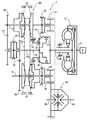
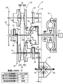
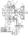
図1に示すように、車両に搭載される無段変速機TはエンジンEのクランクシャフト11にトルクコンバータ12を介して接続された主入力軸13と、主入力軸13に対して平行に配置された第1副入力軸14および第2副入力軸15とを備える。主入力軸13は第1部分13Aおよび第2部分13Bに2分割されており、第1、第2部分13A,13B間に前後進切換機構16が配置される。第1副入力軸14は本発明の第2出力軸を構成し、第2副入力軸15は本発明の第1出力軸を構成する。
As shown in FIG. 1, a continuously variable transmission T mounted on a vehicle is arranged in parallel to a
前後進切換機構16は前進クラッチ17、後進ブレーキ18および遊星歯車機構19を備えており、遊星歯車機構19の第1要素であるリングギヤが第1部分13Aに接続され、遊星歯車機構19の第2要素であるサンギヤが第2部分13Bに接続され、遊星歯車機構19の第3要素であるキャリヤが後進ブレーキ18を介してケーシングに結合可能であり、リングギヤおよびサンギヤが前進クラッチ17を介して相互に結合可能である。従って、前進クラッチ17を係合すると主入力軸13の第1部分13Aおよび第2部分13Bが直結されて車両は前進走行し、後進ブレーキ18を係合すると遊星歯車機構19によって主入力軸13の第1部分13Aの回転が逆回転になり、かつ減速されて主入力軸13の第2部分13Bに伝達され、車両は後進走行する。
The forward /
第1副入力軸14および第2副入力軸15間に配置されたベルト式無段変速機構20は、第1副入力軸14に設けられた第1プーリ21と、第2副入力軸15に設けられた第2プーリ22と、第1、第2プーリ21,22に巻き掛けられた無端ベルト23とを備える。第1、第2プーリ21,22の溝幅は油圧によって相互に逆方向に増減し、第1副入力軸14および第2副入力軸15間の変速比を連続的に変化させることができる。第1プーリ21は、第1副入力軸14に固定された第1固定プーリ21Aと、第1固定プーリ21Aに対して接近・離反可能な第1可動プーリ21Bとで構成される。また第2プーリ22は、第2副入力軸15に固定された第2固定プーリ22Aと、第2固定プーリ22Aに対して接近・離反可能な第2可動プーリ22Bとで構成される。
The belt-type continuously
主入力軸13の第2部分13Bにはドグクラッチよりなる入力切換機構24が設けられる。主入力軸13の第1部分13Aには第1リダクションギヤ25および第1インダクションギヤ27が相対回転自在に支持されており、入力切換機構24のスリーブを中立位置から右動すると第1リダクションギヤ25が主入力軸13の第2部分13Bに結合され、入力切換機構24のスリーブを中立位置から左動すると第1インダクションギヤ27が主入力軸13の第2部分13Bに結合される。第1副入力軸14には第1リダクションギヤ25に噛合する第2リダクションギヤ26が固設され、第2副入力軸15には第1インダクションギヤ27に噛合する第2インダクションギヤ28が固設される。
The
第1副入力軸14には第2ファイナルドライブギヤ29が相対回転自在に支持されており、この第2ファイナルドライブギヤ29は第2出力切換機構30によって第1副入力軸14に結合可能である。また第2副入力軸15には第1ファイナルドライブギヤ31が相対回転自在に支持されており、この第1ファイナルドライブギヤ31は第1出力切換機構32によって第2副入力軸15に結合可能である。第1、第2ファイナルドライブギヤ31,29はディファレンシャルギヤ33のファイナルドリブンギヤ34に噛合し、ディファレンシャルギヤ33から左右に延びるドライブシャフト35,35に左右の駆動輪が接続される。
A second
第1、第2リダクションギヤ25,26により、主入力軸13の第1部分13Aの回転は減速して第1副入力軸14に伝達される。一方、第1、第2インダクションギヤ27,28により、主入力軸13の第1部分13Aの回転は増速して第2副入力軸15に伝達される。
By the first and second reduction gears 25 and 26, the rotation of the
第1リダクションギヤ25から第2リダクションギヤ26へのギヤ比をired とし、第1インダクションギヤ27から第2インダクションギヤ28へのギヤ比をiind とし、ベルト式無段変速機構20の第1プーリ21から第2プーリ22への最小変速比をimin とすると、ired ×imin =iindとなるように各ギヤ比が設定される。また第1ファイナルドライブギヤ31からファイナルドリブンギヤ34へのギヤ比をiloF とし、第2ファイナルドライブギヤ29からファイナルドリブンギヤ34へのギヤ比をihiF とすると、iloF ×imin =ihiF となるように各ギヤ比が設定される。The gear ratio from the
図2には、無段変速機TのLOWモードが示される。LOWモードでは、入力切換機構24がLOW側(右動)に切り換えられ、第1出力切換機構32が係合し、第2出力切換機構30が係合解除し、前後進切換機構16が前進側(前進クラッチ17係合)に切り換えられる。
FIG. 2 shows the LOW mode of the continuously variable transmission T. In the LOW mode, the
その結果、エンジンEの駆動力はクランクシャフト11→トルクコンバータ12→主入力軸13の第1部分13A→前後進切換機構16→主入力軸13の第2部分13B→入力切換機構24→第1リダクションギヤ25→第2リダクションギヤ26→第1副入力軸14→第1プーリ21→無端ベルト23→第2プーリ22→第2副入力軸15→第1出力切換機構32→第1ファイナルドライブギヤ31→ファイナルドリブンギヤ34→ディファレンシャルギヤ33→ドライブシャフト35,35の経路で駆動輪に伝達される。
As a result, the driving force of the engine E is crankshaft 11 →
LOWモードにおいて、ベルト式無段変速機構20は第1副入力軸14側から第2副入力軸15側に駆動力を伝達し、その変速比の変更に応じて無段変速機Tのオーバーオール変速比が変更される。
In the LOW mode, the belt-type continuously
図3には、前記LOWモードから後記HIモードに移行する前半の移行モード1が示される。移行モード1では、入力切換機構24がLOW側(右動)に切り換えられ、第1出力切換機構32が係合し、第2出力切換機構30が係合し、前後進切換機構16が前進側(前進クラッチ17係合)に切り換えられ、前述したLOWモードと後述する直結LOWモード(図7参照)とが同時に確立する。
FIG. 3 shows the
図4には、前記LOWモードから後記HIモードに移行する後半の移行モード2が示される。移行モード2では、入力切換機構24がHI側(左動)に切り換えられ、第1出力切換機構32が係合し、第2出力切換機構30が係合し、前後進切換機構16が前進側(前進クラッチ17係合)に切り換えられ、後述するHIモード(図5参照)と後述する直結HIモード(図8参照)とが同時に確立する。
FIG. 4 shows a second-half transition mode 2 in which the LOW mode is shifted to the HI mode described later. In the transition mode 2, the
移行モード1および移行モード2はLOWモードからHIモードへの移行をスムーズに行うためのものであり、その詳細は後述する。
図5には、無段変速機TのHIモードが示される。HIモードでは、入力切換機構24がHI側(左動)に切り換えられ、第1出力切換機構32が係合解除し、第2出力切換機構30が係合し、前後進切換機構16が前進側(前進クラッチ17係合)に切り換えられる。
FIG. 5 shows the HI mode of the continuously variable transmission T. In the HI mode, the
その結果、エンジンEの駆動力はクランクシャフト11→トルクコンバータ12→主入力軸13の第1部分13A→前後進切換機構16→主入力軸13の第2部分13B→入力切換機構24→第1インダクションギヤ27→第2インダクションギヤ28→第2副入力軸15→第2プーリ22→無端ベルト23→第1プーリ21→第1副入力軸14→第2出力切換機構30→第2ファイナルドライブギヤ29→ファイナルドリブンギヤ34→ディファレンシャルギヤ33→ドライブシャフト35,35の経路で駆動輪に伝達される。
As a result, the driving force of the engine E is crankshaft 11 →
HIモードにおいて、ベルト式無段変速機構20は第2副入力軸15側から第1副入力軸14側に駆動力を伝達し、その変速比の変更に応じて無段変速機Tのオーバーオール変速比が変更される。
In the HI mode, the belt type continuously
図6には、無段変速機Tの後進モードが示される。後進モードでは、入力切換機構24がLOW側(右動)に切り換えられ、第1出力切換機構32が係合し、第2出力切換機構30が係合解除し、前後進切換機構16が後進側(後進ブレーキ18係合)に切り換えられる。
FIG. 6 shows the reverse mode of the continuously variable transmission T. In the reverse mode, the
その結果、エンジンEの駆動力はクランクシャフト11→トルクコンバータ12→主入力軸13の第1部分13A→前後進切換機構16→主入力軸13の第2部分13B→入力切換機構24→第1リダクションギヤ25→第2リダクションギヤ26→第1副入力軸14→第1プーリ21→無端ベルト23→第2プーリ22→第2副入力軸15→第1出力切換機構32→第1ファイナルドライブギヤ31→ファイナルドリブンギヤ34→ディファレンシャルギヤ33→ドライブシャフト35,35の経路で駆動輪に逆回転で伝達される。
As a result, the driving force of the engine E is crankshaft 11 →
後進モードにおいて、ベルト式無段変速機構20は第1副入力軸14側から第2副入力軸15側に駆動力を伝達し、その変速比の変更に応じて無段変速機Tのオーバーオール変速比が変更される。
In the reverse mode, the belt-type continuously
図7には、無段変速機Tの直結LOWモードが示される。直結LOWモードでは、入力切換機構24がLOW側(右動)に切り換えられ、第1出力切換機構32が係合解除し、第2出力切換機構30が係合し、前後進切換機構16が前進側(前進クラッチ17係合)に切り換えられる。
FIG. 7 shows the direct connection LOW mode of the continuously variable transmission T. In the direct connection LOW mode, the
その結果、エンジンEの駆動力はクランクシャフト11→トルクコンバータ12→主入力軸13の第1部分13A→前後進切換機構16→主入力軸13の第2部分13B→入力切換機構24→第1リダクションギヤ25→第2リダクションギヤ26→第1副入力軸14→第2出力切換機構30→第2ファイナルドライブギヤ29→ファイナルドリブンギヤ34→ディファレンシャルギヤ33→ドライブシャフト35,35の経路で駆動輪に伝達される。
As a result, the driving force of the engine E is crankshaft 11 →
直結LOWモードにおいて、ベルト式無段変速機構20は作動せず、無段変速機Tのオーバーオール変速比は一定である。
In the direct connection LOW mode, the belt type continuously
図8には、無段変速機Tの直結HIモードが示される。直結HIモードでは、入力切換機構24がHI側(左動)に切り換えられ、第1出力切換機構32が係合し、第2出力切換機構30が係合解除し、前後進切換機構16が前進側(前進クラッチ17係合)に切り換えられる。
FIG. 8 shows the direct connection HI mode of the continuously variable transmission T. In the direct connection HI mode, the
その結果、エンジンEの駆動力はクランクシャフト11→トルクコンバータ12→主入力軸13の第1部分13A→前後進切換機構16→主入力軸13の第2部分13B→入力切換機構24→第1インダクションギヤ27→第2インダクションギヤ28→第2副入力軸15→第1出力切換機構32→第1ファイナルドライブギヤ31→ファイナルドリブンギヤ34→ディファレンシャルギヤ33→ドライブシャフト35,35の経路で駆動輪に伝達される。
As a result, the driving force of the engine E is crankshaft 11 →
直結HIモードにおいて、ベルト式無段変速機構20は作動せず、無段変速機Tのオーバーオール変速比は一定である。
In the direct connection HI mode, the belt type continuously
次に、LOWモードからHIモードへの移行時の作用を説明する。 Next, the operation when shifting from the LOW mode to the HI mode will be described.
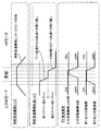
図9に示すように、図2に示すLOWモードでベルト式無段変速機構20の第1プーリ21から第2プーリ22への変速比が次第に減少して最小変速比imin に達したときに、それまで係合解除していた第2出力切換機構30を係合し、図3に示す移行モード1とする。続いて、入力切換機構24をLOW側からHI側に切り換え、図4に示す移行モード2とした後、それまで係合していた第1出力切換機構32を係合解除し、図5に示すHIモードとする。As shown in FIG. 9, when the gear ratio from the
LOWモードの最後およびHIモードの最初において、無段変速機Tのオーバーオール変速比は一致しており、これによりLOWモードからHIモードに切り換わるときの変速ショックの発生が防止される。LOWモードから移行モード1への移行時に第2出力切換機構30が係合するとき、移行モード1から移行モード2への移行時に入力切換機構24がLOW側からHI側に切り換わるとき、移行モード2からHIモードへの移行時に第1出力切換機構32が係合解除するとき、差回転が発生しないようにして入力切換機構24、第1出力切換機構32および第2出力切換機構30のスムーズな作動を可能にしている。
At the end of the LOW mode and the beginning of the HI mode, the overall transmission ratio of the continuously variable transmission T is the same, thereby preventing the occurrence of a shift shock when switching from the LOW mode to the HI mode. When the second
これを詳しく説明するために、仮に、第1リダクションギヤ25から第2リダクションギヤ26へのギヤ比ired を1.5とし、第1インダクションギヤ27から第2インダクションギヤ28へのギヤ比iind を0.75とし、ベルト式無段変速機構20の第1プーリ21から第2プーリ22への最小変速比imin を0.5とし、第1ファイナルドライブギヤ31からファイナルドリブンギヤ34へのギヤ比iloF を4.0とし、第2ファイナルドライブギヤ29からファイナルドリブンギヤ34へのギヤ比ihiF を2.0とし、主入力軸13の回転数を1500rpmとする。In order to explain this in detail, suppose that the gear ratio i red from the
移行モード1の動力伝達経路には、LOWモードの動力伝達経路と直結LOWモードの動力伝達路とが併存するが、LOWモードの動力伝達経路では、主入力軸13が1500rpmで回転すると、第1副入力軸14は第1、第2リダクションギヤ25,26によりired =1.5で減速されて1000rpmとなり、第2副入力軸15はベルト式無段変速機構20によりimin =0.5で増速されて2000rpmとなり、ファイナルドリブンギヤ34は第1ファイナルドライブギヤ31によりiloF =4.0で減速されて500rpmで回転する。一方、直結LOWモードの動力伝達経路では、主入力軸13が1500rpmで回転すると、第1副入力軸14は第1、第2リダクションギヤ25,26によりired =1.5で減速されて1000rpmとなり、ファイナルドリブンギヤ34は第2ファイナルドライブギヤ29によりihiF =2.0で減速されて500rpmで回転する。The power transmission path in the
移行モード2の動力伝達経路には、HIモードの動力伝達経路と直結HIの動力伝達経路とが併存するが、HIモードの動力伝達経路では、主入力軸13が1500rpmで回転すると、第2副入力軸15は第1、第2インダクションギヤ27,28によりiind =0.75で増速されて2000rpmとなり、第1副入力軸14はベルト式無段変速機構20により1/imin =2.0で減速されて1000rpmとなり、ファイナルドリブンギヤ34は第2ファイナルドライブギヤ29によりihiF =2.0で減速されて500rpmで回転する。一方、直結HIモードの動力伝達経路では、主入力軸13が1500rpmで回転すると、第2副入力軸15は第1、第2インダクションギヤ27,28によりiind =0.75で増速されて2000rpmとなり、ファイナルドリブンギヤ34は第1ファイナルドライブギヤ31によりiloF =4.0で減速されて500rpmで回転する。The HI mode power transmission path and the direct connection HI power transmission path coexist in the transition mode 2 power transmission path. In the HI mode power transmission path, when the
以上のように、LOWモード、移行モード1、移行モード2およびHIモードの間で変速するとき、主入力軸13、第1副入力軸14、第2副入力軸15およびファイナルドリブンギヤ34の回転数は全く変化せず、またベルト式無段変速機構20の変速比もimin に維持されるため、入力切換機構24、第1出力切換機構32および第2出力切換機構30の作動を差回転なしでスムーズに行うことができる。As described above, when shifting between the LOW mode, the
また移行モード1から移行モード2への移行時に、ベルト式無段変速機構20は第1プーリ21→第2プーリ22への動力伝達状態から、第2プーリ22→第1プーリ21への動力伝達状態へと切り換わるため、一時的にトルク伝達が途切れる瞬間がある。しかしながら、その瞬間には直結LOWモードおよび直結HIモードが成立してトルクを伝達するため、トルク伝達の途切れによるショックの発生を防止することができる。
When the
以上のように、本実施の形態によれば、ベルト式無段変速機構20に第1、第2リダクションギヤ25,26よりなる減速機と、第1、第2インダクションギヤ27,28よりなる増速機とを組み合わせたことにより、図10に示すように、単独のベルト式無段変速機構(オーバーオール変速比=6〜7程度)に比べて、LOW側の変速比およびOD側の変速比を共に拡大し、10以上の大きなオーバーオール変速比を実現することができる(図11参照)。また本実施の形態の無段変速機Tでは、ベルト式無段変速機構20の変速比が1.0のときのオーバーオール変速比が、単独のベルト式無段変速機構のOD端のオーバーオール変速比に近い値になっており、特にOD側の変速比拡大効果が著しいことが分かる。
As described above, according to the present embodiment, the belt-type continuously
特に、第1、第2リダクションギヤ25,26よりなる減速機と、第1、第2インダクションギヤ27,28よりなる増速機とが独立しているので、それらのギヤ比の設定自由度が高まり、LOWモードではベルト式無段変速機構20の第1、第2プーリ21,22の強度の観点から第1、第2リダクションギヤ25,26のギヤ比を浅くし、HIモードでは高車速時のエンジン回転数を低くするために第1、第2インダクションギヤ27,28のギヤ比を深くすることが可能となる。
In particular, since the speed reducer composed of the first and second reduction gears 25 and 26 and the speed increaser composed of the first and second induction gears 27 and 28 are independent, the degree of freedom in setting their gear ratio is increased. In the LOW mode, the gear ratios of the first and second reduction gears 25 and 26 are made shallow from the viewpoint of the strength of the first and
また第1ファイナルドライブギヤ31および第2ファイナルドライブギヤ29が別持ちになっているので、第1、第2ファイナルドライブギヤ31,29からファイナルドリブンギヤ34への変速比を任意に設定することが可能となり、LOWモードでは発進駆動力を高め、HIモードではエンジンEのクルーズ回転数を低く抑えることができる。
Further, since the first
またLOWモードではベルト式無段変速機構20の手前で第1、第2リダクションギヤ25,26による1回のギヤ噛み合いがあり、HIモードではベルト式無段変速機構20の手前で第1、第2インダクションギヤ27,28による1回のギヤ噛み合いがあるため、チェーンドライブ機構を設けて回転方向を変換する必要がなくなり、構造の簡素化が可能になる。
In the LOW mode, there is one gear engagement by the first and second reduction gears 25 and 26 before the belt type continuously
またHIモードにおいて第1、第2リダクションギヤ27,28のギヤ比を適切に設定することで、従来では通常の高車速時に0.4〜0.5付近になってしまうベルト式無段変速機構20の変速比を1.0付近に設定することが可能となる。これにより、クルージング時に第1、第2プーリ21,22の回転数差を小さくして、ドリブン側の第1プーリ21の遠心油圧キャンセラーを廃止することができるだけでなく、第1、第2プーリ21,22の変速比保持油圧を小さくして油圧ポンプの負荷を低減することができ、しかも第1、第2プーリ21,22に対する無端ベルト23の最小巻き付き半径を大きくし、伝達効率の向上および無端ベルト23の耐久性向上を図ることができる。
Further, by appropriately setting the gear ratio of the first and second reduction gears 27 and 28 in the HI mode, a belt-type continuously variable transmission mechanism that conventionally becomes around 0.4 to 0.5 at a normal high vehicle speed. The transmission gear ratio of 20 can be set to around 1.0. Thereby, not only can the rotational speed difference between the first and
また入力切換機構24および第1出力切換機構32および第2出力切換機構32,30をドグクラッチで構成したので、摩擦クラッチを用いる場合に比べて、引きずり抵抗を低減することができる。特に、入力切換機構24は第1、第2リダクションギヤ25,26側への駆動力の伝達と、第1、第2インダクションギヤ27,28側への駆動力の伝達とを単一のアクチュエータで切り換えることができるので、その構造を簡素化することができる。
Further, since the
また主入力軸13の軸方向に見たとき、入力切換機構24の外周部をベルト式無段変速機構20の第1プーリ21の外周部あるいは第2プーリ22の外周部に重なるように配置することで、第1プーリ21および第2プーリ22間のデッドスペースを有効に利用することが可能となり、主入力軸13、入力切換機構24およびベルト式無段変速機構20を相互に干渉することなくレイアウトすることができる。
Further, when viewed in the axial direction of the
次に、図12〜図19に基づいて本発明の第2の実施の形態を説明する。第2の実施の形態以降の実施の形態において、第1の実施の形態の構成要素に対応する構成要素に第1の実施の形態と同じ符号を付すことで、重複する説明を省略する。 Next, a second embodiment of the present invention will be described with reference to FIGS. In the embodiments after the second embodiment, the same reference numerals as those in the first embodiment are assigned to the components corresponding to the components in the first embodiment, and a duplicate description is omitted.
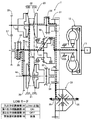
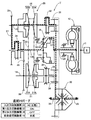
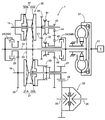
図1に示す第1の実施の形態では主入力軸13が第1部分13Aおよび第2部分13Bに分割されているが、図12に示す第2の実施の形態では主入力軸13は分割されていない。また第1の実施の形態では入力切換機構24は分割されていないが、第2の実施の形態では入力切換機構24がLOW摩擦クラッチ24AおよびHI摩擦クラッチ24Bに分割されている。
In the first embodiment shown in FIG. 1, the
また第2の実施の形態の第2副入力軸15上には、ドグクラッチよりなる前後進切換機構41が設けられる。前後進切換機構41のスリーブが右動すると、第2インダクションギヤ28が第2副入力軸15に結合され、前後進切換機構41のスリーブが左動すると、リバースドライブギヤ42が第2副入力軸15に結合される。リバースドライブギヤ42は、第1インダクションギヤ27と一体に設けたリバースドリブンギヤ43にリバースアイドルギヤ44を介して接続される。
A forward /
また第1の実施の形態では第1ファイナルドライブギヤ31および第1出力切換機構32が第2副入力軸15上に設けられているが、第2の実施の形態ではそれらが新たに設けられた第3出力軸45上に設けられている。第3出力軸45には第1インダクションギヤ27に噛合する第3リダクションギヤ46が相対回転自在に支持されており、第3リダクションギヤ46は第1出力切換機構32を介して第3出力軸45に結合可能である。そして第3出力軸45に固設した第1ファイナルドライブギヤ31がファイナルドリブンギヤ34に噛合する。
In the first embodiment, the first
図13には、無段変速機TのLOWモードが示される。LOWモードでは、入力切換機構24のLOW摩擦クラッチ24Aが係合し、第1出力切換機構32が係合し、第2出力切換機構30が係合解除し、前後進切換機構41が前進側(右動)に切り換えられる。
FIG. 13 shows the LOW mode of the continuously variable transmission T. In the LOW mode, the LOW friction clutch 24A of the
その結果、エンジンEの駆動力はクランクシャフト11→トルクコンバータ12→主入力軸13→入力切換機構24のLOW摩擦クラッチ24A→第1リダクションギヤ25→第2リダクションギヤ26→第1副入力軸14→第1プーリ21→無端ベルト23→第2プーリ22→第2副入力軸15→前後進切換機構41→第2インダクションギヤ28→第1インダクションギヤ27→第3リダクションギヤ46→第1出力切換機構32→第3出力軸45→第1ファイナルドライブギヤ31→ファイナルドリブンギヤ34→ディファレンシャルギヤ33→ドライブシャフト35,35の経路で駆動輪に伝達される。
As a result, the driving force of the engine E is crankshaft 11 →
LOWモードにおいて、ベルト式無段変速機構20は第1副入力軸14側から第2副入力軸15側に駆動力を伝達し、その変速比の変更に応じて無段変速機Tのオーバーオール変速比が変更される。
In the LOW mode, the belt-type continuously
図14には、前記LOWモードから後記HIモードに移行する前半の移行モード1が示される。移行モード1では、入力切換機構24のLOW摩擦クラッチ24Aが係合し、第1出力切換機構32が係合し、第2出力切換機構30が係合し、前後進切換機構41が前進側(右動)に切り換えられ、前述したLOWモードと後述する直結LOWモード(図18参照)とが同時に確立する。
FIG. 14 shows the
図15には、前記LOWモードから後記HIモードに移行する後半の移行モード2が示される。移行モード2では、入力切換機構24のHI摩擦クラッチ24Bが係合し、第1出力切換機構32が係合し、第2出力切換機構30が係合し、前後進切換機構41が前進側(右動)に切り換えられ、後述するHIモード(図16参照)と後述する直結HIモード(図19参照)とが同時に確立する。
FIG. 15 shows the latter-half transition mode 2 in which the LOW mode is shifted to the HI mode described later. In the transition mode 2, the HI friction clutch 24B of the
移行モード1および移行モード2はLOWモードからHIモードへの移行をスムーズに行うためのものであり、その詳細は後述する。
図16には、無段変速機TのHIモードが示される。HIモードでは、入力切換機構24のHI摩擦クラッチ24Bが係合し、第1出力切換機構32が係合解除し、第2出力切換機構30が係合し、前後進切換機構41が前進側(右動)に切り換えられる。
FIG. 16 shows the HI mode of the continuously variable transmission T. In the HI mode, the HI friction clutch 24B of the
その結果、エンジンEの駆動力はクランクシャフト11→トルクコンバータ12→主入力軸13→入力切換機構24のHI摩擦クラッチ24B→第1インダクションギヤ27→第2インダクションギヤ28→前後進切換機構41→第2副入力軸15→第2プーリ22→無端ベルト23→第1プーリ21→第1副入力軸14→第2出力切換機構30→第2ファイナルドライブギヤ29→ファイナルドリブンギヤ34→ディファレンシャルギヤ33→ドライブシャフト35,35の経路で駆動輪に伝達される。
As a result, the driving force of the engine E is:
HIモードにおいて、ベルト式無段変速機構20は第2副入力軸15側から第1副入力軸14側に駆動力を伝達し、その変速比の変更に応じて無段変速機Tのオーバーオール変速比が変更される。
In the HI mode, the belt type continuously
図17には、無段変速機Tの後進モードが示される。後進モードでは、入力切換機構24のLOW摩擦クラッチ24Aが係合し、第1出力切換機構32が係合し、第2出力切換機構30が係合解除し、前後進切換機構41が後進側(左動)に切り換えられる。
FIG. 17 shows the reverse mode of the continuously variable transmission T. In the reverse mode, the LOW friction clutch 24A of the
その結果、エンジンEの駆動力はクランクシャフト11→トルクコンバータ12→主入力軸13→入力切換機構24のLOW摩擦クラッチ24A→第1リダクションギヤ25→第2リダクションギヤ26→第1副入力軸14→第1プーリ21→無端ベルト23→第2プーリ22→第2副入力軸15→前後進切換機構41→リバースドライブギヤ42→リバースアイドルギヤ44→リバースドリブンギヤ43→第1インダクションギヤ27→第3リダクションギヤ46→第1出力切換機構32→第3出力軸45→第1ファイナルドライブギヤ31→ファイナルドリブンギヤ34→ディファレンシャルギヤ33→ドライブシャフト35,35の経路で駆動輪に伝達される。
As a result, the driving force of the engine E is crankshaft 11 →
後進モードにおいて、ベルト式無段変速機構20は第1副入力軸14側から第2副入力軸15側に駆動力を伝達し、その変速比の変更に応じて無段変速機Tのオーバーオール変速比が変更される。
In the reverse mode, the belt-type continuously
図18には、無段変速機Tの直結LOWモードが示される。直結LOWモードでは、入力切換機構24のLOW摩擦クラッチ24Aが係合し、第1出力切換機構32が係合解除し、第2出力切換機構30が係合し、前後進切換機構41が前進側(右動)に切り換えられる。
FIG. 18 shows the direct connection LOW mode of the continuously variable transmission T. In the direct connection LOW mode, the LOW friction clutch 24A of the
その結果、エンジンEの駆動力はクランクシャフト11→トルクコンバータ12→主入力軸13→入力切換機構24のLOW摩擦クラッチ24A→第1リダクションギヤ25→第2リダクションギヤ26→第1副入力軸14→第2出力切換機構30→第2ファイナルドライブギヤ29→ファイナルドリブンギヤ34→ディファレンシャルギヤ33→ドライブシャフト35,35の経路で駆動輪に伝達される。
As a result, the driving force of the engine E is crankshaft 11 →
直結LOWモードにおいて、ベルト式無段変速機構20は作動ぜず、無段変速機Tのオーバーオール変速比は一定である。
In the direct connection LOW mode, the belt-type continuously
図19には、無段変速機Tの直結HIモードが示される。直結HIモードでは、入力切換機構24のHI摩擦クラッチ24Bが係合し、第1出力切換機構32が係合し、第2出力切換機構30が係合解除し、前後進切換機構41が前進側(右動)または中立に切り換えられる。
FIG. 19 shows a direct connection HI mode of continuously variable transmission T. In the direct connection HI mode, the HI friction clutch 24B of the
その結果、エンジンEの駆動力はクランクシャフト11→トルクコンバータ12→入力切換機構24のHI摩擦クラッチ24B→第1インダクションギヤ27→第3リダクションギヤ46→第1出力切換機構32→第3出力軸45→第1ファイナルドライブギヤ31→ファイナルドリブンギヤ34→ディファレンシャルギヤ33→ドライブシャフト35,35の経路で駆動輪に伝達される。
As a result, the driving force of the engine E is:
直結HIモードにおいて、ベルト式無段変速機構20は作動ぜず、無段変速機Tのオーバーオール変速比は一定である。
In the direct connection HI mode, the belt type continuously
第1の実施の形態では、第1リダクションギヤ25から第2リダクションギヤ26へのギヤ比をired とし、第1インダクションギヤ27から第2インダクションギヤ28へのギヤ比をiind とし、ベルト式無段変速機構20の第1プーリ21から第2プーリ22への最小変速比をimin としたときに、ired ×imin =iind となるように各ギヤ比を設定し、また第1ファイナルドライブギヤ31からファイナルドリブンギヤ34へのギヤ比をiloF とし、第2ファイナルドライブギヤ29からファイナルドリブンギヤ34へのギヤ比をihiF としたときに、iloF ×imin =ihiF となるように各ギヤ比を設定することで、入力切換機構24、第1出力切換機構32および第2出力切換機構30の作動を差回転なしでスムーズに行えるようにしている。In the first embodiment, the gear ratio from the
一方、第2の実施の形態では、第1ファイナルドライブギヤ31が第2副入力軸15に設けられておらず、別軸である第3出力軸45に設けられており、第2副入力軸15および第3出力軸45間に第2インダクションギヤ28、第1インダクションギヤ27および第3リダクションギヤ46が介在している。従って、第1の実施の形態のiloF ×imin =ihiF の関係に代えて、第2の実施の形態ではiloF ×imin ×(isec /iind )=ihiF の関係が成立するように、第2インダクションギヤ28、第1インダクションギヤ27および第3リダクションギヤ46の歯数を設定することが必要である。On the other hand, in the second embodiment, the first
isec は、第1インダクションギヤ27から第3リダクションギヤ46への変速比である。従って、例えば第1インダクションギヤ27から第2インダクションギヤ28への変速比であるiind =0.75、isec =1.2と設定し、isec /iind =1.6とすることで、第1の実施の形態と同様にired =1.5、ihiF =2.0、imin =0.5に設定した場合でも、iloF =2.5に設定することで第2副入力軸15および第3出力軸45が同一回転数になり、前後進切換機構41、第1出力切換機構32および第2出力切換機構30の作動を差回転なしでスムーズに行うことができる。また第1の実施の形態のiloF =4.0の第1ファイナルドライブギヤ31の外径と等しくなるようにiloF =2.5の第1ファイナルドライブギヤ31を設定することで、第2ファイナルドライブギヤ29およびファイナルドリブンギヤ34の外径を第1の実施の形態よりも小さくすることができる。i sec is a gear ratio from the
また本実施の形態によれば、図13に示すように、LOWモードにおいて第1、第2インダクションギヤ27,28を第2インダクションギヤ28側から第1インダクションギヤ27側にトルクが伝達されるので、本来は増速機である第1、第2インダクションギヤ27,28を減速機として利用してオーバーオール変速比のLOW側の変速比を増加させることができる。
Further, according to the present embodiment, as shown in FIG. 13, torque is transmitted from the
また第1出力切換機構32を第3出力軸45に設けたので、第1出力切換機構32を第2副入力軸15あるいは主入力軸12に設ける場合に比べて無段変速機Tの軸方向寸法を小型化することができる。
Further, since the first
次に、図20および図21に基づいて本発明の第3の実施の形態を説明する。 Next, a third embodiment of the present invention will be described with reference to FIGS.
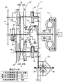
第2の実施の形態(図12参照)および第3の実施の形態(図20参照)を比較すると明らかなように、第3の実施の形態は、第2副入力軸15に設けた前後進切換機構41の機能が第2の実施の形態と異なっている。前後進切換機構24は第2副入力軸15に固設した第2インダクションギヤ28と、第2副入力軸15に相対回転自在に支持したリバースドライブギヤ42とを結合可能であり、またリバースドリブンギヤ43は第1インダクションギヤ27に相対回転自在に支持され、第1出力切換機構32により第1インダクションギヤ27に結合可能である。
As is clear from a comparison between the second embodiment (see FIG. 12) and the third embodiment (see FIG. 20), the third embodiment is a forward / backward movement provided on the second
リバースドリブンギヤ43は、第1副入力軸14に相対回転自在に支持した第3リダクションギヤ46に噛合し、第3リダクションギヤ46は第2出力切換機構30により第1副入力軸14に結合可能である。そして第3リダクションギヤ46と一体に設けた単一のファイナルドライブギヤ47がファイナルドリブンギヤ34に噛合する。
The reverse driven
第3の実施の形態は、第2の実施の形態の第3出力軸45を廃止し、その第3出力軸45に設けた第1出力切換機構32を主入力軸13に移動させたものに相当しており、その機能は第2の実施の形態と基本的に同じである。第3の実施の形態の入力切換機構24のLOW摩擦クラッチ24A、入力切換機構24のHI摩擦クラッチ24B、前後進切換機構41、第1出力切換機構32および第2出力切換機構30の係合表が、図21に示される。
In the third embodiment, the
本実施の形態によれば、第2の実施の形態の第3出力軸45が不要になるため、軸数を1本減らして自動変速機Tの径方向寸法を小型化することができる。但し、第3リダクションギヤ46を第3出力軸45から第2副入力軸15に移動させたことで自動変速機Tの軸方向寸法は若干増加する。
According to the present embodiment, the
次に、図22に基づいて本発明の第4の実施の形態を説明する。 Next, a fourth embodiment of the present invention will be described with reference to FIG.
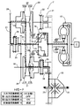
第4の実施の形態は第3の実施の形態の変形であり、ファイナルドライブギヤ47およびファイナルドリブンギヤ34をベベルギヤで構成し、ディファレンシャルギヤ33の軸線を主入力軸13、第1副入力軸14および第2副入力軸15の軸線に対して直交させたものである。
The fourth embodiment is a modification of the third embodiment, in which the
第3および第4の実施の形態では、第3リダクションギヤ46を第3出力軸45から第2副入力軸15に移動させたことで自動変速機Tの軸方向寸法は若干増加するが、第4の実施の形態を採用することで、車体前後方向の寸法の制約が少ない無段変速機Tを縦置きしたFFのレイアウトを採用することが可能となり、車体への搭載性が向上する。
In the third and fourth embodiments, the axial dimension of the automatic transmission T is slightly increased by moving the
次に、図23および図24に基づいて本発明の第5の実施の形態を説明する。 Next, a fifth embodiment of the present invention will be described with reference to FIGS.
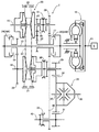
第1〜第4の実施の形態の無段変速機構はベルト式無段変速機構20であるが、第5の実施の形態の無段変速機構は公知のトロイダル式無段変速機構20′である。トロイダル式無段変速機構20′は、変速軸48に固設した一対の入力ディスク49,49と、一対の入力ディスク49,49間で変速軸48に回転自在に支持した出力ディスク50との間に、4個のパワーローラ51…が傾転可能に配置される。
The continuously variable transmission mechanism of the first to fourth embodiments is a belt-type continuously
主入力軸13の外周に配置された前後進切換機構16は遊星歯車機構19からなり、主入力軸13に相対回転自在に支持したサンギヤとキャリヤとが後進クラッチ18′を介して相互に結合可能であり、キャリヤがケーシングに前進ブレーキ17′を介して結合可能である。遊星歯車機構19のサンギヤは入力切換機構24のLOW摩擦クラッチ24Aを介して主入力軸13に結合可能であり、遊星歯車機構19のリングギヤと一体に設けた第1リダクションギヤ25がトロイダル式無段変速機構20′の変速軸48に固設した第2リダクションギヤ26に噛合する。また主入力軸13に相対回転自在に支持した第1インダクションギヤ27がトロイダル式無段変速機構20′の出力ディスク50に固設した第2インダクションギヤ28に噛合し、第1インダクションギヤ27は入力切換機構24のHI摩擦クラッチ24Bを介して主入力軸13に結合可能である。
The forward /
トロイダル式無段変速機構20′は、ベルト式無段変速機構20と異なり、第2リダクションギヤ26および第2インダクションギヤ28の回転方向が逆になるため、遊星歯車機構19を用いて第2リダクションギヤ26の回転方向を逆転させることで、前進走行時における主入力軸13上の要素の回転方向を一致させている。
Unlike the belt-type continuously
第1インダクションギヤ27と一体に設けたLOW第1出力ギヤ52が出力軸57に相対回転自在に支持したLOW第2出力ギヤ53に噛合し、遊星歯車機構19のサンギヤと一体に設けたHI第1出力ギヤ54が出力軸57に相対回転自在に支持したHI第2出力ギヤ55に噛合する。そしてLOW第2出力ギヤ53およびHI第2出力ギヤ55はドグクラッチよりなる出力切換機構56を介して出力軸57に選択的に結合可能である。
The LOW
従って、図24の係合表に示すように、LOWモードにおいて入力切換機構24のLOWクラッチ24Aを係合し、出力切換機構56をLOW側(左動)に切り換え、前後進切換機構16の前進ブレーキ17′を係合すると、エンジンEの駆動力はクランクシャフト11→トルクコンバータ12→主入力軸13→LOW摩擦クラッチ24A→遊星歯車機構19→第1リダクションギヤ25→第2リダクションギヤ26→変速軸48→入力ディスク49,49→パワーローラ51…→出力ディスク50→第2インダクションギヤ28→第1インダクションギヤ27→LOW第1出力ギヤ52→LOW第2出力ギヤ53→出力切換機構56→出力軸57→ファイナルドライブギヤ47→ファイナルドリブンギヤ34→ディファレンシャルギヤ33→ドライブシャフト35,35の経路で駆動輪に伝達される。
Therefore, as shown in the engagement table of FIG. 24, in the LOW mode, the LOW clutch 24A of the
またHIモードにおいて入力切換機構24のHIクラッチ24Bを係合し、出力切換機構56をHI側(右動)に切り換え、前後進切換機構16の前進ブレーキ17′を係合すると、エンジンEの駆動力はクランクシャフト11→トルクコンバータ12→主入力軸13→HI摩擦クラッチ24B→第1インダクションギヤ27→第2インダクションギヤ28→出力ディスク50→パワーローラ51…→入力ディスク49,49→変速軸48→第2リダクションギヤ26→第1リダクションギヤ25→遊星歯車機構19→HI第1出力ギヤ54→HI第2出力ギヤ55→出力切換機構56→出力軸57→ファイナルドライブギヤ47→ファイナルドリブンギヤ34→ディファレンシャルギヤ33→ドライブシャフト35,35の経路で駆動輪に伝達される。
In the HI mode, when the HI clutch 24B of the
また後進モードにおいて入力切換機構24のLOWクラッチ24Aを係合し、出力切換機構56をLOW側(左動)に切り換え、前後進切換機構16の後進クラッチ18′を係合すると、エンジンEの駆動力は前記LOWモードと同じ経路で伝達されるが、遊星歯車機構19で回転方向が逆転されないことで、車両を後進走行させることができる。
Further, when the LOW clutch 24A of the
またLOW⇔HI移行モードの前半では、前記LOWモードと直結LOWモードとが同時に確立し、直結LOWモードにおいてエンジンEの駆動力はクランクシャフト11→トルクコンバータ12→主入力軸13→LOW摩擦クラッチ24A→HI第1出力ギヤ54→HI第2出力ギヤ55→出力切換機構56→出力軸57→ファイナルドライブギヤ47→ファイナルドリブンギヤ34→ディファレンシャルギヤ33→ドライブシャフト35,35の経路で駆動輪に伝達される。
In the first half of the LOW-HI transition mode, the LOW mode and the direct connection LOW mode are simultaneously established. In the direct connection LOW mode, the driving force of the engine E is crankshaft 11 →
またLOW⇔HI移行モードの後半では前記HIモードと直結HIモードとが同時に確立し、直結HIモードにおいてエンジンEの駆動力はクランクシャフト11→トルクコンバータ12→主入力軸13→HI摩擦クラッチ24B→LOW第1出力ギヤ52→LOW第2出力ギヤ53→出力切換機構56→出力軸57→ファイナルドライブギヤ47→ファイナルドリブンギヤ34→ディファレンシャルギヤ33→ドライブシャフト35,35の経路で駆動輪に伝達される。
In the latter half of the LOW-HI transition mode, the HI mode and the direct connection HI mode are simultaneously established. In the direct connection HI mode, the driving force of the engine E is crankshaft 11 →
よって、LOW摩擦クラッチ24AおよびHI摩擦クラッチ24Bの掴み変えおよび出力切換機構56の切換を同時に行うことで、LOWモードおよびHIモードの切り換えをスムーズに行うことができる。
Therefore, by switching the LOW friction clutch 24A and the HI friction clutch 24B and switching the
本実施の形態によれば、エンジンEの駆動力を第1、第2リダクションギヤ25,26からトロイダル式無段変速機構20′を経て第1、第2インダクションギヤ27,28から出力したり、エンジンEの駆動力を第1、第2インダクションギヤ27,28からトロイダル式無段変速機構20′を経て第1、第2リダクションギヤ25,26から出力したりすることができる。 According to the present embodiment, the driving force of the engine E is output from the first and second induction gears 27 and 28 from the first and second reduction gears 25 and 26 via the toroidal continuously variable transmission mechanism 20 ', The driving force of the engine E can be output from the first and second reduction gears 25 and 26 from the first and second induction gears 27 and 28 through the toroidal continuously variable transmission mechanism 20 '.
以上、本発明の実施の形態を説明したが、本発明はその要旨を逸脱しない範囲で種々の設計変更を行うことが可能である。 The embodiments of the present invention have been described above, but various design changes can be made without departing from the scope of the present invention.
例えば、本発明の無段変速機構は実施の形態のベルト式無段変速機構20やトロイダル式無段変速機構20′に限定されず、正逆二つの方向に駆動力を伝達しながら変速を行う任意の変速機構を採用することができる。
For example, the continuously variable transmission mechanism of the present invention is not limited to the belt-type continuously
Claims (12)
無段変速機構(20,20′)と、
前記主入力軸(13)を前記無段変速機構(20,20′)に接続する第1入力経路と、
前記主入力軸(13)を前記無段変速機構(20,20′)に接続する第2入力経路と、
前記主入力軸(13)の駆動力を前記第1入力経路あるいは前記第2入力経路に選択的に伝達する入力切換機構(24)と、
前記無段変速機構(20,20′)から所定の変速比に変速された駆動力を出力する第1出力経路と、
前記無段変速機構(20,20′)から所定の変速比に変速された駆動力を出力する第2出力経路と、
前記無段変速機構(20,20′)が出力する駆動力を前記第1出力経路あるいは前記第2出力経路に選択的に伝達する出力切換機構(30,32,56)と、
を備える無段変速機において、
前記第1入力経路には前記無段変速機構(20,20′)への入力を減速する第1減速機(25,26)を配置し、前記第2入力経路には前記無段変速機構(20,20′)への入力を増速する増速機(27,28)を配置し、前記第1出力経路には前記無段変速機構(20,20′)からの出力を減速する第2減速機(31,34)を配置し、前記第2出力経路には前記無段変速機構(20,20′)からの出力を減速する、前記第2減速機(31,34)と異なる減速比を持つ第3減速機(29,34)を配置したことを特徴とする無段変速機。A main input shaft (13) to which a driving force from a driving source (E) is input;
Continuously variable transmission mechanism (20, 20 ');
A first input path connecting the main input shaft (13) to the continuously variable transmission mechanism (20, 20 ');
A second input path for connecting the main input shaft (13) to the continuously variable transmission mechanism (20, 20 ');
An input switching mechanism (24) for selectively transmitting the driving force of the main input shaft (13) to the first input path or the second input path;
A first output path for outputting a driving force shifted from the continuously variable transmission mechanism (20, 20 ') to a predetermined speed ratio;
A second output path for outputting a driving force shifted from the continuously variable transmission mechanism (20, 20 ') to a predetermined gear ratio;
An output switching mechanism (30, 32, 56) for selectively transmitting the driving force output by the continuously variable transmission mechanism (20, 20 ') to the first output path or the second output path;
In a continuously variable transmission comprising:
A first speed reducer (25, 26) that decelerates an input to the continuously variable transmission mechanism (20, 20 ') is disposed in the first input path, and the continuously variable transmission mechanism (25, 26) is disposed in the second input path. 20 and 20 '), a speed increaser (27, 28) for increasing the input speed is arranged, and a second speed reducing the output from the continuously variable transmission mechanism (20, 20') is provided in the first output path. A reduction gear ratio different from that of the second reduction gear (31, 34), in which a reduction gear (31, 34) is disposed, and the output from the continuously variable transmission mechanism (20, 20 ') is reduced on the second output path. A continuously variable transmission comprising a third reduction gear (29, 34) having
前記増速機は一対のギヤ(27,28)からなり、一方のギヤ(27)が前記入力切換機構(24)で前記主入力軸(13)に係脱可能であり、他方のギヤ(28)が前記無段変速機構(20)に連なる第2副入力軸(15)に固設されることを特徴とする、請求項1に記載の無段変速機。The first reduction gear includes a pair of gears (25, 26). One gear (25) can be engaged with and disengaged from the main input shaft (13) by the input switching mechanism (24), and the other gear ( 26) is fixed to the first auxiliary input shaft (14) connected to the continuously variable transmission mechanism (20),
The speed-up gear is composed of a pair of gears (27, 28). One gear (27) can be engaged with and disengaged from the main input shaft (13) by the input switching mechanism (24), and the other gear (28). The continuously variable transmission according to claim 1, characterized in that the second auxiliary input shaft (15) connected to the continuously variable transmission mechanism (20) is fixed.
前記第1摩擦クラッチ(24A)は前記第1減速機の一方のギヤ(25)を前記主入力軸(13)に結合可能であり、前記第2摩擦クラッチ(24B)は前記増速機の一方のギヤ(27)を前記主入力軸(13)に結合可能であることを特徴とする、請求項2〜請求項4の何れか1項に記載の無段変速機。The input switching mechanism (24) includes a first friction clutch (24A) disposed in the vicinity of an end portion on the opposite side of the drive source (E) in the axial direction of the main input shaft (13), and the main input shaft. A second friction clutch (24B) disposed in the vicinity of the end on the drive source (E) side in the axial direction of (13),
The first friction clutch (24A) can connect one gear (25) of the first reduction gear to the main input shaft (13), and the second friction clutch (24B) is one of the speed increaser. The continuously variable transmission according to any one of claims 2 to 4, characterized in that the gear (27) can be coupled to the main input shaft (13).
前記第1入力経路は前記入力ディスク(49)および前記出力ディスク(50)の一方に前記駆動源(E)からの駆動力を伝達するとともに、前記第2入力経路は前記入力ディスク(49)および前記出力ディスク(50)の他方に前記駆動源(E)からの駆動力を伝達し、
前記第1入力経路に前記駆動源(E)の駆動力が入力されるときは前記第2入力経路が前記第1出力経路として機能し、前記第2入力経路に前記駆動源(E)の駆動力が入力されるときは前記第1入力経路が前記第2出力経路として機能することを特徴とする、請求項1に記載の無段変速機。The continuously variable transmission mechanism (20 ′) includes an input disk (49), an output disk (50), and a power roller (51) sandwiched between the input disk (49) and the output disk (50). Prepared,
The first input path transmits driving force from the drive source (E) to one of the input disk (49) and the output disk (50), and the second input path is connected to the input disk (49) and the output disk (50). Transmitting the driving force from the driving source (E) to the other of the output disk (50);
When the driving force of the driving source (E) is input to the first input path, the second input path functions as the first output path, and the driving source (E) is driven to the second input path. The continuously variable transmission according to claim 1, wherein when a force is input, the first input path functions as the second output path.
Applications Claiming Priority (1)
| Application Number | Priority Date | Filing Date | Title |
|---|---|---|---|
| PCT/JP2012/063029 WO2013175568A1 (en) | 2012-05-22 | 2012-05-22 | Continuously variable transmission |
Publications (2)
| Publication Number | Publication Date |
|---|---|
| JP5832002B2 true JP5832002B2 (en) | 2015-12-16 |
| JPWO2013175568A1 JPWO2013175568A1 (en) | 2016-01-12 |
Family
ID=49623300
Family Applications (1)
| Application Number | Title | Priority Date | Filing Date |
|---|---|---|---|
| JP2014516551A Expired - Fee Related JP5832002B2 (en) | 2012-05-22 | 2012-05-22 | Continuously variable transmission |
Country Status (7)
| Country | Link |
|---|---|
| US (1) | US9909657B2 (en) |
| JP (1) | JP5832002B2 (en) |
| CN (1) | CN104334924B (en) |
| BR (1) | BR112014028845A2 (en) |
| DE (1) | DE112012006411T5 (en) |
| MX (1) | MX2014014101A (en) |
| WO (1) | WO2013175568A1 (en) |
Families Citing this family (43)
| Publication number | Priority date | Publication date | Assignee | Title |
|---|---|---|---|---|
| CN102226467B (en) | 2005-12-09 | 2014-06-25 | 福博科知识产权有限责任公司 | Continuously variable transmission |
| EP1811202A1 (en) | 2005-12-30 | 2007-07-25 | Fallbrook Technologies, Inc. | A continuously variable gear transmission |
| US8996263B2 (en) | 2007-11-16 | 2015-03-31 | Fallbrook Intellectual Property Company Llc | Controller for variable transmission |
| BR112015028781A2 (en) | 2013-05-28 | 2017-07-25 | Honda Motor Co Ltd | continuously variable transmission |
| US9874269B2 (en) | 2013-05-28 | 2018-01-23 | Honda Motor Co., Ltd. | Continuously variable transmission |
| US10088025B2 (en) * | 2013-09-24 | 2018-10-02 | Jatco Ltd | Automatic transmission for electric vehicle |
| US10054202B2 (en) | 2013-09-25 | 2018-08-21 | Jatco Ltd | Torque cam device and belt-type continuously variable transmission |
| KR101828191B1 (en) | 2013-10-08 | 2018-02-09 | 쟈트코 가부시키가이샤 | Control device for continuously variable transmission equipped with auxiliary transmission |
| EP3056773A4 (en) * | 2013-10-08 | 2017-01-25 | Jatco Ltd | Control device for continuously variable transmission equipped with auxiliary transmission |
| CN105814343B (en) * | 2013-12-09 | 2019-09-10 | 舍弗勒技术股份两合公司 | CVT transmission |
| US10240667B2 (en) * | 2013-12-09 | 2019-03-26 | Schaeffler Technologies AG & Co. KG | CVT drive train |
| DE112014005595A5 (en) * | 2013-12-09 | 2016-11-03 | Schaeffler Technologies AG & Co. KG | CVT |
| JP6243451B2 (en) * | 2014-01-17 | 2017-12-06 | 本田技研工業株式会社 | Vehicle transmission |
| JP6072715B2 (en) * | 2014-03-05 | 2017-02-01 | 本田技研工業株式会社 | Continuously variable transmission |
| JP6092139B2 (en) * | 2014-03-06 | 2017-03-08 | 本田技研工業株式会社 | Control device for continuously variable transmission |
| JP6071927B2 (en) * | 2014-03-06 | 2017-02-01 | 本田技研工業株式会社 | Control device for continuously variable transmission |
| WO2015133601A1 (en) * | 2014-03-06 | 2015-09-11 | 本田技研工業株式会社 | Control device for stepless transmission |
| WO2015133600A1 (en) * | 2014-03-06 | 2015-09-11 | 本田技研工業株式会社 | Stepless transmission control device |
| CN106104092B (en) * | 2014-03-10 | 2018-01-19 | 本田技研工业株式会社 | The control device of buncher |
| JP6203669B2 (en) * | 2014-03-17 | 2017-09-27 | 本田技研工業株式会社 | Control device for continuously variable transmission |
| JP6246327B2 (en) * | 2014-03-26 | 2017-12-13 | 本田技研工業株式会社 | Control device for continuously variable transmission |
| JP6220302B2 (en) * | 2014-03-26 | 2017-10-25 | 本田技研工業株式会社 | Control device for continuously variable transmission |
| KR101611078B1 (en) * | 2014-09-23 | 2016-04-11 | 현대자동차주식회사 | Transmission for vehicle |
| JP6227158B2 (en) * | 2014-10-01 | 2017-11-08 | 本田技研工業株式会社 | Continuously variable transmission |
| JP6327128B2 (en) * | 2014-11-21 | 2018-05-23 | トヨタ自動車株式会社 | Power transmission control device |
| US10138986B2 (en) | 2014-12-16 | 2018-11-27 | Honda Motor Co., Ltd. | Continuously variable transmission |
| JP6471637B2 (en) * | 2015-07-24 | 2019-02-20 | スズキ株式会社 | Continuously variable transmission |
| JP6326395B2 (en) * | 2015-10-20 | 2018-05-16 | 本田技研工業株式会社 | transmission |
| JP6259798B2 (en) * | 2015-10-22 | 2018-01-10 | 本田技研工業株式会社 | transmission |
| JP6310900B2 (en) * | 2015-11-25 | 2018-04-11 | 本田技研工業株式会社 | transmission |
| JP6271495B2 (en) * | 2015-12-10 | 2018-01-31 | 本田技研工業株式会社 | transmission |
| US10047861B2 (en) | 2016-01-15 | 2018-08-14 | Fallbrook Intellectual Property Company Llc | Systems and methods for controlling rollback in continuously variable transmissions |
| JP6575377B2 (en) * | 2016-01-28 | 2019-09-18 | スズキ株式会社 | Continuously variable transmission |
| JP6575375B2 (en) * | 2016-01-28 | 2019-09-18 | スズキ株式会社 | Continuously variable transmission |
| US10023266B2 (en) | 2016-05-11 | 2018-07-17 | Fallbrook Intellectual Property Company Llc | Systems and methods for automatic configuration and automatic calibration of continuously variable transmissions and bicycles having continuously variable transmissions |
| US10309506B2 (en) * | 2016-05-16 | 2019-06-04 | Ford Global Technologies, Llc | Multiple-mode continuously variable transmission |
| JP2018184990A (en) * | 2017-04-25 | 2018-11-22 | トヨタ自動車株式会社 | Vehicular power transmission apparatus |
| CN109149861A (en) * | 2018-08-30 | 2019-01-04 | 宁波博生机电科技有限公司 | A kind of main shaft drives constant speed generation device peculiar to vessel |
| US11215268B2 (en) | 2018-11-06 | 2022-01-04 | Fallbrook Intellectual Property Company Llc | Continuously variable transmissions, synchronous shifting, twin countershafts and methods for control of same |
| US11174922B2 (en) | 2019-02-26 | 2021-11-16 | Fallbrook Intellectual Property Company Llc | Reversible variable drives and systems and methods for control in forward and reverse directions |
| JP7387222B2 (en) * | 2019-02-28 | 2023-11-28 | ダイハツ工業株式会社 | transmission |
| CN113685527B (en) * | 2021-09-07 | 2024-01-26 | 芜湖万里扬变速器有限公司 | Longitudinally-arranged stepless speed changer |
| CN113700821B (en) * | 2021-09-07 | 2024-01-30 | 芜湖万里扬变速器有限公司 | Longitudinally-arranged stepless speed changer |
Citations (2)
| Publication number | Priority date | Publication date | Assignee | Title |
|---|---|---|---|---|
| JP2000320630A (en) * | 1999-05-12 | 2000-11-24 | Fuji Heavy Ind Ltd | Continuously variable transmission device |
| US20090017959A1 (en) * | 2007-06-21 | 2009-01-15 | Luk Lamellen Und Kupplungsbau Beteiligungs Kg | Vehicle transmission with continuously variable transmission ratio |
Family Cites Families (12)
| Publication number | Priority date | Publication date | Assignee | Title |
|---|---|---|---|---|
| US4458558A (en) | 1981-08-05 | 1984-07-10 | Aisin Seiki Kabushiki Kaisha | Variable V-belt type continuously variable transmission for vehicles |
| NL8105451A (en) | 1981-12-03 | 1983-07-01 | Doornes Transmissie Bv | TRANSMISSION, PARTICULARLY FOR A VEHICLE, FITTED WITH A HYDRODYNAMIC TORQUE INVERTER. |
| FR2548318B1 (en) | 1983-06-30 | 1985-12-13 | Renault | DRIVE TRANSMISSION |
| US4539866A (en) | 1983-11-03 | 1985-09-10 | General Motors Corporation | Continuously variable transmission |
| DE4234629C2 (en) | 1991-10-25 | 2002-07-18 | Volkswagen Ag | Continuously variable transmission for motor vehicles |
| DE4207093A1 (en) | 1992-03-06 | 1993-04-01 | Daimler Benz Ag | Gear change transmission for car drive - has output shaft in coaxial structure directly connectable to one main shaft |
| DE19631072A1 (en) * | 1996-08-01 | 1998-02-05 | Zahnradfabrik Friedrichshafen | Gear change mechanism for propulsion of car |
| WO2004038257A1 (en) | 2002-10-22 | 2004-05-06 | Luk Lamellen Und Kupplungsbau Beteiligungs Kg | Power-split transmission having an infinitely variable ratio |
| CN101228370B (en) | 2005-07-23 | 2013-05-29 | 舍弗勒技术股份两合公司 | Power split transmission with a plurality of transmission ratio ranges, the transmission ratios of which can be adjusted steplessly |
| JP4332518B2 (en) | 2005-10-06 | 2009-09-16 | 本田技研工業株式会社 | Power transmission control device |
| JP4983301B2 (en) * | 2007-02-23 | 2012-07-25 | 株式会社豊田中央研究所 | Transmission |
| JP5162792B2 (en) | 2009-05-11 | 2013-03-13 | 本田技研工業株式会社 | Power transmission device |
-
2012
- 2012-05-22 DE DE112012006411.9T patent/DE112012006411T5/en not_active Withdrawn
- 2012-05-22 MX MX2014014101A patent/MX2014014101A/en unknown
- 2012-05-22 JP JP2014516551A patent/JP5832002B2/en not_active Expired - Fee Related
- 2012-05-22 CN CN201280073366.0A patent/CN104334924B/en not_active Expired - Fee Related
- 2012-05-22 US US14/400,989 patent/US9909657B2/en active Active
- 2012-05-22 WO PCT/JP2012/063029 patent/WO2013175568A1/en active Application Filing
- 2012-05-22 BR BR112014028845A patent/BR112014028845A2/en not_active IP Right Cessation
Patent Citations (2)
| Publication number | Priority date | Publication date | Assignee | Title |
|---|---|---|---|---|
| JP2000320630A (en) * | 1999-05-12 | 2000-11-24 | Fuji Heavy Ind Ltd | Continuously variable transmission device |
| US20090017959A1 (en) * | 2007-06-21 | 2009-01-15 | Luk Lamellen Und Kupplungsbau Beteiligungs Kg | Vehicle transmission with continuously variable transmission ratio |
Also Published As
| Publication number | Publication date |
|---|---|
| CN104334924A (en) | 2015-02-04 |
| JPWO2013175568A1 (en) | 2016-01-12 |
| MX2014014101A (en) | 2015-06-23 |
| WO2013175568A1 (en) | 2013-11-28 |
| US20150133257A1 (en) | 2015-05-14 |
| DE112012006411T5 (en) | 2015-02-26 |
| BR112014028845A2 (en) | 2017-06-27 |
| CN104334924B (en) | 2017-03-15 |
| US9909657B2 (en) | 2018-03-06 |
Similar Documents
| Publication | Publication Date | Title |
|---|---|---|
| JP5832002B2 (en) | Continuously variable transmission | |
| JP5800088B2 (en) | Power transmission device for vehicle | |
| JP5765485B2 (en) | Power transmission device for vehicle | |
| JP5861778B2 (en) | Power transmission device for vehicle | |
| JP6014968B2 (en) | Continuously variable transmission | |
| WO2013175582A1 (en) | Vehicle power transmission device | |
| JP5922843B2 (en) | Continuously variable transmission | |
| JP2002048213A (en) | Speed change gear equipped with variable speed change mechanism | |
| WO2016052021A1 (en) | Stepless transmission | |
| JP2006046468A (en) | Continuously variable transmission | |
| JP5861777B2 (en) | Power transmission device for vehicle | |
| JP2015031312A (en) | Power transmission mechanism | |
| WO2013046362A1 (en) | Continuously variable transmission | |
| JP6365246B2 (en) | Automatic transmission | |
| JP5963227B2 (en) | Continuously variable transmission | |
| JP6072715B2 (en) | Continuously variable transmission | |
| JP6123733B2 (en) | Vehicle transmission | |
| JP2002122207A (en) | Transmission | |
| JP6474661B2 (en) | Power transmission device for vehicle | |
| JP5835476B2 (en) | Power transmission device for vehicle | |
| JP4738298B2 (en) | Continuously variable transmission |
Legal Events
| Date | Code | Title | Description |
|---|---|---|---|
| TRDD | Decision of grant or rejection written | ||
| A01 | Written decision to grant a patent or to grant a registration (utility model) |
Free format text: JAPANESE INTERMEDIATE CODE: A01 Effective date: 20150930 |
|
| A61 | First payment of annual fees (during grant procedure) |
Free format text: JAPANESE INTERMEDIATE CODE: A61 Effective date: 20151023 |
|
| R150 | Certificate of patent or registration of utility model |
Ref document number: 5832002 Country of ref document: JP Free format text: JAPANESE INTERMEDIATE CODE: R150 |
|
| R250 | Receipt of annual fees |
Free format text: JAPANESE INTERMEDIATE CODE: R250 |
|
| LAPS | Cancellation because of no payment of annual fees |