JP5831425B2 - Solar cell inspection equipment - Google Patents
Solar cell inspection equipment Download PDFInfo
- Publication number
- JP5831425B2 JP5831425B2 JP2012236640A JP2012236640A JP5831425B2 JP 5831425 B2 JP5831425 B2 JP 5831425B2 JP 2012236640 A JP2012236640 A JP 2012236640A JP 2012236640 A JP2012236640 A JP 2012236640A JP 5831425 B2 JP5831425 B2 JP 5831425B2
- Authority
- JP
- Japan
- Prior art keywords
- light
- irradiation unit
- cell
- solar cell
- light irradiation
- Prior art date
- Legal status (The legal status is an assumption and is not a legal conclusion. Google has not performed a legal analysis and makes no representation as to the accuracy of the status listed.)
- Expired - Fee Related
Links
Images


Classifications
-
- Y—GENERAL TAGGING OF NEW TECHNOLOGICAL DEVELOPMENTS; GENERAL TAGGING OF CROSS-SECTIONAL TECHNOLOGIES SPANNING OVER SEVERAL SECTIONS OF THE IPC; TECHNICAL SUBJECTS COVERED BY FORMER USPC CROSS-REFERENCE ART COLLECTIONS [XRACs] AND DIGESTS
- Y02—TECHNOLOGIES OR APPLICATIONS FOR MITIGATION OR ADAPTATION AGAINST CLIMATE CHANGE
- Y02E—REDUCTION OF GREENHOUSE GAS [GHG] EMISSIONS, RELATED TO ENERGY GENERATION, TRANSMISSION OR DISTRIBUTION
- Y02E10/00—Energy generation through renewable energy sources
- Y02E10/50—Photovoltaic [PV] energy
Description
この発明は、例えば、反射防止膜成膜後の太陽電池セルを検査する太陽電池セルの検査装置に関する。 The present invention relates to a solar cell inspection apparatus that inspects a solar cell after formation of an antireflection film, for example.
太陽電池セルの生産工程においては、太陽電池セルの形状の欠陥、表面の欠陥、あるいは、内部の欠陥の検査が実行される。 In the production process of solar cells, inspection of defects in the shape of solar cells, defects on the surface, or internal defects is performed.
特許文献1には、レーザ光源により半導体ウエハに対してレーザ光を照射するとともに、半導体ウエハの表面において反射した光学像を撮像装置により撮像し、欠陥検出部により撮像された半導体ウエハの画像データから欠陥を抽出することにより、半導体ウエハの表面に存在する欠陥を検査する欠陥検査装置が開示されている。 In Patent Document 1, laser light is emitted to a semiconductor wafer by a laser light source, an optical image reflected on the surface of the semiconductor wafer is picked up by an image pickup device, and image data of the semiconductor wafer picked up by a defect detection unit is used. A defect inspection apparatus that inspects defects existing on the surface of a semiconductor wafer by extracting defects is disclosed.
また、特許文献2には、赤外線光源から半導体ウエハに対して赤外線を照射するとともに、半導体ウエハを透過した赤外線を赤外線カメラにより撮像する赤外線検査装置が開示されている。この赤外線検査装置においては、クラック等の異常部分と多結晶シリコン基板部分とで赤外線の透過状態が異なることを利用して、半導体ウエハ内部のマイクロクラックを検出する構成となっている。 Further, Patent Document 2 discloses an infrared inspection apparatus that irradiates a semiconductor wafer with infrared light from an infrared light source and images the infrared light transmitted through the semiconductor wafer with an infrared camera. This infrared inspection apparatus is configured to detect microcracks inside a semiconductor wafer by utilizing the fact that infrared transmission states are different between an abnormal portion such as a crack and a polycrystalline silicon substrate portion.
太陽電池セルの製造プロセスにおいて、反射防止膜の成膜後の太陽電池セルの検査が実行される。そして、検査で良品と判断された太陽電池セルに対して、電極の印刷と焼成が実行される。この太陽電池セルの検査としては、太陽電池セルの端縁付近に発生する割れや欠け等の形状の欠陥を検査する形状欠陥検査、太陽電池セルに乗ったパーティクル、反射防止膜のピンホール、反射防止膜の膜厚むら、電極生成後のパターン等の表面の欠陥を検査する表面欠陥検査、太陽電池セルの内部に生じたマイクロクラック等の内部の欠陥を検査する内部欠陥検査等がある。 In the manufacturing process of the solar battery cell, the solar battery cell is inspected after the antireflection film is formed. And the printing and baking of an electrode are performed with respect to the photovoltaic cell judged to be non-defective by the test | inspection. This solar cell inspection includes shape defect inspection for inspecting defects such as cracks and chips generated near the edge of the solar cell, particles on the solar cell, pinholes in the antireflection film, reflection There are non-uniformity in the thickness of the protective film, surface defect inspection for inspecting surface defects such as patterns after electrode generation, and internal defect inspection for inspecting internal defects such as microcracks generated inside the solar battery cell.
ここで、上述した形状欠陥検査時には、太陽電池セルの裏面側から可視光を照明して撮影を行っている。また、上述した表面欠陥検査時には、太陽電池セルの表面側から可視光を照明して撮影を行っている。さらに、上述した内部欠陥検査時には、太陽電池セルの裏面側から赤外線を照射して太陽電池セルを透過した赤外光を撮影している。 Here, at the time of the shape defect inspection described above, imaging is performed by illuminating visible light from the back side of the solar battery cell. Moreover, at the time of the surface defect inspection mentioned above, it image | photographs by illuminating visible light from the surface side of a photovoltaic cell. Furthermore, at the time of the above-described internal defect inspection, infrared light that has been transmitted through the solar cell by irradiating infrared rays from the back side of the solar cell is photographed.
従来、形状の検査および表面状態の検査を行う検査装置と、マイクロクラックの検査を行う検査装置は、使用する照明光の波長が異なることから、各々、別々の装置として構成されている。このため、可視光を使用した形状の検査または表面状態の検査と、赤外光を使用したマイクロクラックの検査とを実行するためには、複数の装置が必要となることから、検査にコストがかかり、また、装置の専有面積が大きくなるばかりではなく、検査に時間がかかるという問題が生ずる。 Conventionally, an inspection apparatus that inspects a shape and a surface state and an inspection apparatus that inspects a microcrack are configured as separate apparatuses because the wavelengths of illumination light to be used are different. For this reason, in order to perform the inspection of the shape using visible light or the inspection of the surface condition, and the inspection of micro cracks using infrared light, a plurality of devices are required, so the inspection is costly. In addition, there is a problem that not only the area occupied by the apparatus increases, but also the inspection takes time.
この発明は上記課題を解決するためになされたものであり、赤外光を使用した検査と可視光を使用した検査とを単一の装置により実行することが可能な太陽電池セルの検査装置を提供することを目的とする。 This invention was made in order to solve the said subject, and the test | inspection apparatus of the photovoltaic cell which can perform the test | inspection using infrared light, and the test | inspection using visible light by a single apparatus. The purpose is to provide.
請求項1に記載の発明は、太陽電池セルを検査する太陽電池セルの検査装置であって、前記太陽電池セルの第1面に向けて赤外光を照射する第1光照射部と、前記第1光照射部から照射された赤外光の照射方向を前記太陽電池セルの端縁方向に向ける指向性変更部材と、前記指向性変更部材により指向性を変更された赤外光が通過可能な開口部が形成され、当該開口部のサイズが前記第1光照射部のサイズより小さく、外周部のサイズが前記太陽電池セルより大きな額縁状の形状を有する拡散反射板と、前記拡散反射板に対して可視光を照射する第2光照射部と、前記第1光照射部より照射され、前記太陽電池セルを前記第1面側から当該第1面とは逆側の第2面側に透過した赤外光を測定する第1測定部と、前記第2光照射部より照射され、前記拡散反射板で反射された後に、前記太陽電池セルの端縁付近を前記第1面側から前記第2面側に透過した可視光を測定する第2測定部と、前記第1測定部で測定した赤外光の画像に基づいて、前記太陽電池セルの内部の欠陥を判定する内部欠陥判定部と、前記第2測定部で測定した可視光の画像に基づいて、前記太陽電池セルの端縁付近の形状の欠陥を判定する形状欠陥判定部とを備えたことを特徴とする。 The invention according to claim 1 is a solar cell inspection device that inspects solar cells, the first light irradiation unit irradiating infrared light toward the first surface of the solar cells, and A directivity changing member that directs the irradiation direction of infrared light emitted from the first light irradiation unit toward the edge direction of the solar battery cell, and infrared light whose directivity has been changed by the directivity changing member can pass therethrough. A diffuse reflector having a frame-like shape in which a small opening is formed, the size of the opening is smaller than the size of the first light irradiator, and the size of the outer periphery is larger than that of the solar battery cell, and the diffuse reflector A second light irradiating unit that irradiates visible light with respect to the first light irradiating unit, and the solar cell is moved from the first surface side to the second surface side opposite to the first surface. Irradiated from the first measurement unit that measures the transmitted infrared light and the second light irradiation unit. A second measuring unit that measures visible light transmitted from the first surface side to the second surface side in the vicinity of an edge of the solar battery cell after being reflected by the diffuse reflector; and the first measuring unit. Based on the measured infrared light image, an internal defect determination unit that determines an internal defect of the solar cell, and an edge of the solar cell based on the visible light image measured by the second measurement unit And a shape defect determination unit for determining a defect in the shape near the edge.
請求項2に記載の発明は、請求項1に記載の発明において、前記太陽電池セルの第2面に対して可視光を照射する第3光照射部をさらに備え、前記内部欠陥判定部は、前記第3光照射部から照射され前記太陽電池セルの第2面で反射した可視光を前記第2測定部で測定した可視光の画像と、前記第1測定部で測定した赤外光の画像とを比較することにより、前記太陽電池セルの内部の欠陥を判定する。 Invention of Claim 2 is further provided with the 3rd light irradiation part which irradiates visible light with respect to the 2nd surface of the said photovoltaic cell in invention of Claim 1, The said internal defect determination part is An image of visible light measured by the second measuring unit and an image of infrared light measured by the first measuring unit irradiated from the third light irradiating unit and reflected by the second surface of the solar cell. Are compared to determine the internal defects of the solar battery cell.
請求項3に記載の発明は、請求項2に記載の発明において、前記第3光照射部から照射される可視光は青色光である。 According to a third aspect of the present invention, in the second aspect of the present invention, the visible light emitted from the third light irradiation unit is blue light.
請求項4に記載の発明は、請求項1に記載の発明において、前記太陽電池セルの第2面に対して可視光を照射する第4光照射部と、前記第4光照射部から照射され前記太陽電池セルの第2面で反射した可視光を前記第2測定部で測定した可視光の画像に基づいて、前記太陽電池セルの表面の欠陥を測定する表面欠陥測定部とをさらに備える。 Invention of Claim 4 is irradiated from the 4th light irradiation part which irradiates visible light with respect to the 2nd surface of the said photovoltaic cell in the invention of Claim 1, and the said 4th light irradiation part. And a surface defect measuring unit that measures defects on the surface of the solar cell based on an image of visible light obtained by measuring the visible light reflected by the second surface of the solar cell by the second measuring unit.
請求項5に記載の発明は、請求項4に記載の発明において、前記第4光照射部から照射される可視光は、赤色光である。 The invention according to claim 5 is the invention according to claim 4, wherein the visible light emitted from the fourth light irradiation unit is red light.
請求項6に記載の発明は、請求項5に記載の発明において、前記第4光照射部から照射される可視光は、赤色光の他に緑色光と青色光とを含み、前記第2測定部で測定した可視光の画像に基づいて太陽電池セルの表面に形成された反射防止膜の膜厚を測定する。 The invention according to claim 6 is the invention according to claim 5, wherein the visible light emitted from the fourth light irradiator includes green light and blue light in addition to red light, and the second measurement. The film thickness of the antireflection film formed on the surface of the solar battery cell is measured based on the visible light image measured by the unit.
請求項7に記載の発明は、請求項1に記載の発明において、前記第1光照射部より照射され前記太陽電池セルを前記第1面側から当該第1面とは逆側の第2面側に透過した赤外光を前記第1測定部に導くとともに、前記第2光照射部より照射され前記拡散反射板で反射された後に前記太陽電池セルの端縁付近を前記第1面側から前記第2面側に透過した可視光を前記第2測定部に導くビームスプリッタを備える。 The invention according to claim 7 is the invention according to claim 1, wherein the solar cell is irradiated from the first light irradiating unit from the first surface side to the second surface opposite to the first surface. Infrared light transmitted to the side is guided to the first measurement unit, and is irradiated from the second light irradiation unit and reflected by the diffuse reflection plate, and then the vicinity of the edge of the solar battery cell from the first surface side. A beam splitter that guides visible light transmitted to the second surface side to the second measurement unit;
請求項1に記載の発明によれば、赤外光を使用した内部欠陥検査と可視光を使用した形状欠陥検査とを単一の装置により実行することが可能となる。このとき、額縁状の拡散反射板の作用により、太陽電池セルの端縁からの赤外光の回り込みを防止して太陽電池セル全域での内部欠陥検査を可能とするとともに、可視光を太陽電池セルの端縁付近に好適に照射することが可能となる。 According to the first aspect of the present invention, it is possible to execute the internal defect inspection using infrared light and the shape defect inspection using visible light by a single device. At this time, by the action of the frame-shaped diffuse reflector, the infrared light from the edge of the solar cell is prevented from wrapping around, enabling the inspection of internal defects throughout the solar cell, and the visible light to the solar cell. It is possible to suitably irradiate the vicinity of the edge of the cell.
請求項2に記載の発明によれば、可視光による反射画像と赤外光による透過画像とを比較することにより、太陽電池セルの結晶粒界とマイクロクラックとを識別することができ、太陽電池セル内部の欠陥をより正確に判定することが可能となる。 According to the invention described in claim 2, by comparing the reflected image by visible light and the transmitted image by infrared light, the crystal grain boundary and the microcrack of the solar battery cell can be identified, and the solar battery It becomes possible to more accurately determine the defects inside the cell.
請求項3に記載の発明によれば、青色光により反射画像を高速かつ正確に認識することが可能となる。 According to the third aspect of the present invention, it is possible to recognize the reflected image at high speed and accurately with blue light.
請求項4に記載の発明によれば、内部欠陥検査、形状欠陥検査および表面欠陥検査を単一の装置により実行することができ、検査のために必要なコストと時間を最小とすることが可能となる。 According to the invention described in claim 4, the internal defect inspection, the shape defect inspection, and the surface defect inspection can be performed by a single apparatus, and the cost and time required for the inspection can be minimized. It becomes.
請求項5に記載の発明によれば、赤色光により太陽電池セルの結晶粒界の影響を受けることなく表面欠陥検査を実行することが可能となる。 According to the fifth aspect of the present invention, the surface defect inspection can be performed without being affected by the crystal grain boundary of the solar battery cell by the red light.
請求項6に記載の発明によれば、太陽電池セルの表面に形成された反射防止膜の膜厚を測定することが可能となる。 According to invention of Claim 6, it becomes possible to measure the film thickness of the anti-reflective film formed in the surface of the photovoltaic cell.
請求項7に記載の発明によれば、装置の調整を容易に実行することができ、第1測定部で測定される赤外光の画像と第2測定部で測定される可視光の画像の精度を向上させることが可能となる。 According to the seventh aspect of the present invention, the apparatus can be easily adjusted, and the infrared light image measured by the first measuring unit and the visible light image measured by the second measuring unit can be adjusted. The accuracy can be improved.
以下、この発明の実施の形態を図面に基づいて説明する。図1は、この発明に係る太陽電池セルの検査装置の概要図である。 Hereinafter, embodiments of the present invention will be described with reference to the drawings. FIG. 1 is a schematic diagram of a solar cell inspection apparatus according to the present invention.
この太陽電池セルの検査装置は、前段の成膜工程においてその表面に反射防止膜が成膜された太陽電池セル100を検査するためのものであり、太陽電池セル100の裏面(第1面)に向けて赤外光を照射する第1光照射部11と、この第1光照射部11から照射された赤外光の照射方向を太陽電池セル100の端縁方向に向ける指向性変更部材としてのフレネルレンズ21と、このフレネルレンズ21により指向性を変更された赤外光が通過可能な開口部23が形成された額縁状の形状を有する拡散反射板22と、この拡散反射板22に対して可視光のうちの赤色光を照射する第2光照射部12と、太陽電池セルの表面(第2面)に対して可視光のうちの青色光を照射する第3光照射部13と、太陽電池セルの表面に対して可視光(赤色光、青色光および緑色光)を照射する第4光照射部14と、赤外光を観察するための第1CCDカメラ31と、可視光を観察するための第2CCDカメラ32と、太陽電池セル100を裏面側から表面側に向かって透過した赤外光を反射させて第1CCDカメラ31に導くとともに、太陽電池セル100の表面で反射した可視光および太陽電池セル100の端縁付近を通過した可視光を通過させて第2CCDカメラ32に導くダイクロイックミラーからなるビームスプリッタ33とを備える。
This solar cell inspection apparatus is for inspecting a
この図に示すように、第4光照射部14は、その波長が470nm程度の青色光を出射する青色光源41と、その波長が525nm程度の緑色光を出射する緑色光源42と、その波長が640nm程度の赤色光を出射する赤色光源43と、太陽電池セル100の上部を覆い、太陽電池セル100の表面を均一な光強度で照射するためのドーム型の反射型拡散板44とを備える。青色光源41と緑色光源42と赤色光源43とは、太陽電池セル100と平行な平面内において、円周上に等間隔をあけて配置されている。また、反射型拡散板44の上方には、開口部45が形成されている。
As shown in this figure, the fourth
この第4光照射部14においては、青色光源41を点灯させた場合には、青色光が反射型拡散板44で反射された後、太陽電池セル100の表面全域を均一に照射する。また、緑色光源42を点灯させた場合には、緑色光が反射型拡散板44で反射された後、太陽電池セル100の表面全域を均一に照射する。さらに、赤色光源43を点灯させた場合には、赤色光が反射型拡散板44で反射された後、太陽電池セル100の表面全域を均一に照射する。
In the fourth
図2は、上述した第1光照射部11、第2光照射部12および第3光照射部13を太陽電池セル100等とともに示す概要図である。
FIG. 2 is a schematic diagram showing the above-described first
第1光照射部11は、太陽電池セル100と対向する領域に列設された赤外光を出射する複数のLED素子51を備える。この第1光照射部11の上面には、第1光照射部11における各LED素子51から照射された赤外光の照射方向を太陽電池セル100の端縁方向に向けるフレネルレンズ21が配設されている。そして、このフレネルレンズ21の上方には、額縁状の拡散反射板22が配設されている。この拡散反射板22は、フレネルレンズ21からの赤外光が通過可能な開口部23が形成された額縁状の形状を有し、開口部23以外の領域では第1光照射部11における各LED素子51から出射された赤外光を遮断する構成を有する。そして、この拡散反射板22の上面は、そこに照射された光を拡散する光拡散面となっている。
The first
第2光照射部12は、額縁状の拡散反射板22の上方に拡散反射板22と対向するように列設されたその波長が640nm程度の赤色光を出射する複数のLED素子52を備える。第2光照射部12における各LED素子52から出射された赤色光は、拡散反射板22の表面に照射されて拡散され、太陽電池セル100の端縁付近に照射される。
The second
第3光照射部13は、太陽電池セル100の斜め上方に列設されたその波長が470nm程度の青色光を出射する複数のLED素子53を備える。第3光照射部13における各LED素子53より出射された青色光は、太陽電池セル100の表面全域に照射される。
The third
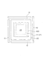
図3は、太陽電池セル100と、第1光照射部11と、拡散反射板22と、第2光照射部12との配置関係を示す平面図である。
FIG. 3 is a plan view showing an arrangement relationship among the
この図に示すように、第1光照射部11およびフレネルレンズ21と、太陽電池セル100とは、互いに相似する矩形状をしており、第1光照射部11およびフレネルレンズ21のサイズは、太陽電池セル100のサイズより若干小さくなっている。また、拡散反射板22は、その開口部23のサイズが第1光照射部11およびフレネルレンズ21のサイズより小さく、外周部のサイズが太陽電池セル100より大きくなっている。そして、第2光照射部12は、拡散反射板22を取り囲むように配置されている。
As shown in this figure, the 1st
図4は、この発明に係る太陽電池セルの検査装置の制御系を示すブロック図である。 FIG. 4 is a block diagram showing a control system of the solar cell inspection apparatus according to the present invention.
この太陽電池セルの検査装置は、論理演算を実行するCPUや、装置の制御に必要な動作プログラムが格納されたROMおよび制御時にデータ等が一時的にストアされるRAM等の記憶装置を有するコンピュータから構成され、装置全体を制御する制御部60を備える。この制御部60は、上述した第1光照射部11、第2光照射部12、第3光照射部13、第4光照射部14、第1CCDカメラ31および第2CCDカメラ32と接続されている。
This solar cell inspection device is a computer having a storage device such as a CPU that executes logical operations, a ROM that stores an operation program necessary for controlling the device, and a RAM that temporarily stores data during control. And a
この制御部60は、第3光照射部13から照射され太陽電池セル100の表面で反射した青色光を第2CCDカメラ32で測定した可視光の画像と、第1光照射部11から照射され太陽電池セル100を透過した赤外光を第1CCDカメラ31で測定した赤外光の画像とを比較することにより、太陽電池セル100の内部の欠陥を判定する内部欠陥判定部61を備える。また、この制御部60は、第2光照射部12より照射されて拡散反射板22で反射された後に太陽電池セル100の端縁付近を通過した赤色光を第2CCDカメラ32で測定した可視光の画像に基づいて、太陽電池セル100の端縁付近の形状の欠陥を判定する形状欠陥判定部62を備える。また、この制御部60は、第4光照射部14から照射され太陽電池セル100の表面で反射した赤色光を第2CCDカメラ32で測定した可視光の画像に基づいて、太陽電池セル100の表面の欠陥を測定する表面欠陥判定部63を備える。さらに、この制御部60は、第4光照射部14から照射された太陽電池セル100の表面で反射した赤色光と緑色光と青色光とを第2CCDカメラ32で測定した可視光の画像に基づいて、太陽電池セルの表面に形成された反射防止膜の膜厚を測定する膜厚測定部64を備える。
The
以上のような構成を有する太陽電池セルの検査装置において太陽電池セル100の検査を実行する場合においては、図示しない搬送機構により、図1に示すように、太陽電池セル100を検査位置に搬送する。この状態において、第1光照射部11による太陽電池セル100の裏面全域への赤外光の照射と、第2光照射部12による拡散反射板22を介しての太陽電池セル100の端縁付近への赤色光の照射と、第3光照射部13による太陽電池セル100の表面全域への青色光の照射と、第4光照射部14による太陽電池セル100の表面全域への青色光、緑色光、赤色光の照射とを順次実行するとともに、ビームスプリッタ33で反射された赤外光を第1CCDカメラ31により、また、ビームスプリッタ33を通過した可視光を第2CCDカメラ32により、各々、観察する。これにより、後述するように、太陽電池セル100における内部欠陥判定、形状欠陥判定、表面欠陥判定および反射防止膜の膜厚の測定が実行される。
When the inspection of the
なお、第2CCDカメラ32は、第2光照射部12から出射され太陽電池セル100端縁付近を通過した赤色光の画像と、第3光照射部13から出射され太陽電池セル100の表面で反射された青色光の反射画像と、第4光照射部14から出射され太陽電池セル100の表面で反射した可視光の反射画像を測定することになる。この場合においては、制御部60により、第2光照射部12、第3光照射部13および第4光照射部14の青色光源41、緑色光源42、赤色光源43を順次点灯させるとともに、その点灯と同期させて第2CCDカメラ32による画像の取り込みを制御することにより、各種のデータを識別して取得する構成となっている。
The
上述した内部欠陥判定は、次のようにして実行される。すなわち、第1光照射部11の各LED素子51から出射された赤外光が、フレネルレンズ21によりその照射方向を太陽電池セル100の端縁方向に向けられ、また、その照射領域を額縁状の形状を有する拡散反射板22により制限されて太陽電池セル100の裏面に照射される。この場合においては、第1光照射部11から照射された赤外光の太陽電池セル100に対する照射領域は、拡散反射板22における開口部23の形状を適正なものとすることにより、太陽電池セル100の裏面全域と正確に一致させることが可能となる。そして、この赤外光は、その指向性を太陽電池セル100の外側に向かう方向とされている。これらにより、太陽電池セル100の端縁付近に照射された赤外光が、太陽電池セル100の端縁から表面側に回り込むことを防止することができる。このため、第1CCDカメラ31によりこの赤外線透過画像を撮影した場合に、太陽電池セル100の端縁付近画像をも正確に認識することが可能となる。
The above-described internal defect determination is executed as follows. That is, the infrared light emitted from each
すなわち、太陽電池セル100の端縁付近に照射された赤外光が、太陽電池セル100の端縁から表面側に回り込んだ場合には、第1CCDカメラ31によりこの赤外線透過画像を撮影した場合に、太陽電池セル100の端縁付近の画像がハレーション等により認識できなくなるという問題が生ずる。このため、太陽電池セル100の端縁付近に照射された赤外光の強度を弱くする対応も考えられるが、このような対応を取った場合には、第1光照射部11から太陽電池セル100に照射された赤外光が対応電池セルの裏面側から表面側に透過しないという問題が生ずる。このため、この発明に係る太陽電池セルの検査装置においては、太陽電池セル100に照射する赤外光を、フレネルレンズ21により指向性を太陽電池セル100の外側に向かう方向とするとともに、額縁状の形状を有する拡散反射板22によりその照射領域を適切に管理することで、上述した赤外光の回り込みによる問題の発生を防止している。
That is, when the infrared light irradiated to the vicinity of the edge of the
図5は、このようにして撮影された太陽電池セル100の赤外線透過画像を示す模式図である。
FIG. 5 is a schematic diagram showing an infrared transmission image of the
この図に示すように、太陽電池セル100の赤外線透過画像には、マイクロクラック103が映し出されている。一方、太陽電池セル100は多数の結晶粒101から構成されていることから、赤外線透過画像には、その結晶粒界102も映し出される。このため、この結晶粒界102とマイクロクラック103との識別が困難となる場合がある。このような問題に対応するため、この太陽電池セルの検査装置においては、第3光照射部13から出射された青色光の反射画像を利用してマイクロクラック103を正確に抽出して認識する構成を採用している。
As shown in this figure, the
図6は、太陽電池セル100の青色光反射画像を示す模式図である。
FIG. 6 is a schematic diagram showing a blue light reflection image of the
太陽電池セル100の表面に第3光照射部13の各LED素子53から青色光を照射してその反射画像を測定した場合には、図6に示すように、反射画像に結晶粒101と結晶粒界102とが映し出される。このため、図5に示す太陽電池セル100の赤外線透過画像と図6に示す青色光による反射画像とを比較することにより、マイクロクラック103等の内部欠陥の有無を、正確に判定することが可能となる。この赤外光による透過画像と可視光による反射画像とを比較することによる太陽電池セル100の内部の欠陥の判定は、図4に示す制御部60における内部欠陥判定部61により実行される。
When the surface of the
なお、太陽電池セル100の内部の欠陥の判定を行う場合に、可視光のうち、特に、青色光を利用しているのは、強度の強い青色光を利用することにより、短時間で結晶粒界102を鮮明に映し出すことが可能となるためである。
In addition, when determining the defect inside the
また、上述した形状欠陥判定は、次のようにして実行される。すなわち、第2光照射部12の各LED素子52から出射された赤色光が拡散反射板22により反射および拡散された後、太陽電池セル100の端縁付近を通過する。この赤色光を第2CCDカメラ32により測定することで、太陽電池セル100の端縁付近に発生する割れや欠け等の形状の欠陥を検査することが可能となる。この形状欠陥判定は、図4に示す制御部60における形状欠陥判定部62により実行される。
Further, the shape defect determination described above is executed as follows. That is, the red light emitted from each
このとき、太陽電池セル100の端縁付近に照射された赤色光が太陽電池セル100の端縁から表面側に回り込んだ場合には、太陽電池セル100の端縁付近の画像がハレーション等により認識できなくなるという問題が生ずる。このため、この形状欠陥判定時においては、第2光照射部12より照射される赤色光の強度をハレーションを生じない程度の強度とすることにより、このような問題の発生を防止している。このとき、第2光照射部12の各LED素子52より照射される赤色光の強度を小さなものとした場合には、これらのLED素子52の像がそのまま第2CCDカメラ32により認識されてしまう場合がある。しかしながら、この発明に係る太陽電池セルの検査装置においては、第2光照射部12から出射された赤色光を拡散反射板22により拡散して反射した後に、太陽電池セル100の端縁付近に照射することから、このような問題の発生を効果的に防止することが可能となる。
At this time, when the red light irradiated to the vicinity of the edge of the
また、上述した表面欠陥判定は、以下のようにして実行される。すなわち、第4光照射部14における赤色光源43から赤色光を出射させ、この赤色光を反射型拡散板44で反射させて太陽電池セル100の表面全域に均一に照射する。そして、太陽電池セル100の表面で反射した赤色光を第2CCDカメラ32によって撮影することにより、太陽電池セル100の表面欠陥を検査することが可能となる。なお、この表面欠陥判定は、図4に示す制御部60における表面欠陥判定部63により実行される。
Further, the above-described surface defect determination is executed as follows. That is, red light is emitted from the
なお、太陽電池セル100の表面の欠陥の判定を行う場合に、可視光のうち、特に、赤色光を利用しているのは、表面欠陥の判定時に、可視光の反射画像に太陽電池セル100における結晶粒界102が映し出されることを防止するためである。
In addition, when determining the defect of the surface of the
さらに、上述した膜厚測定は、以下のようにして実行される。すなわち、第4光照射部14における青色光源41と、緑色光源42と、赤色光源43とを順次点灯させて、太陽電池セル100の青色光による反射画像と、太陽電池セル100の緑色光による反射画像と、太陽電池セル100の赤色光による反射画像とを得る。そして、このようにして得られた3枚の反射画像の相対強度比(スペクトル)に基づいて反射防止膜の膜厚を演算する。なお、この膜厚測定は、図4に示す制御部60における膜厚測定部64により実行される。
Furthermore, the film thickness measurement described above is performed as follows. That is, the blue
上述した実施形態においては、内部欠陥判定と、形状欠陥判定と、表面欠陥判定と、膜厚測定とを単一の装置で実行している。このため、装置の専有面積を小さくすることができ、また、検査に要する時間をより短時間とすることが可能となる。ただし、表面欠陥判定と膜厚測定とを、別の装置で実施するようにしてもよい。 In the embodiment described above, the internal defect determination, the shape defect determination, the surface defect determination, and the film thickness measurement are performed by a single device. Therefore, the area occupied by the apparatus can be reduced, and the time required for the inspection can be shortened. However, the surface defect determination and the film thickness measurement may be performed by different apparatuses.
また、上述した実施形態においては、太陽電池セル100を裏面側から表面側に向かって透過した赤外光を反射させて第1CCDカメラ31に導くとともに、太陽電池セル100の表面で反射した可視光および太陽電池セル100の端縁付近を通過した可視光を通過させて第2CCDカメラ32に導くダイクロイックミラーからなるビームスプリッタ33を利用して、同軸上の赤外光と可視光とを対応するCCDカメラに案内している。しかしながら、赤外光と可視光とを異なる軸線に沿って対応するCCDカメラに案内する構成としてもよい。
In the above-described embodiment, the infrared light transmitted through the
さらに、上述した実施形態においては、太陽電池セル100の赤外線透過画像と青色光による反射画像とを比較してマイクロクラック103等の内部欠陥の有無をより正確に判定するため、第3光照射部13を利用して太陽電池セル100の表面に青色光を照射している。しかしながら、第4光照射部14における青色光源41からの青色光を利用して太陽電池セル100の青色光による反射画像を得ることにより、第3光照射部13を省略するようにしてもよい。
Further, in the above-described embodiment, the third light irradiation unit is used to more accurately determine the presence / absence of internal defects such as the
11 第1光照射部
12 第2光照射部
13 第3光照射部
14 第4光照射部
21 フレネルレンズ
22 拡散反射板
23 開口部
31 第1CCDカメラ
32 第2CCDカメラ
33 ビームスプリッタ
41 青色光源
42 緑色光源
43 赤色光源
44 反射型拡散板
45 開口部
51 LED素子
52 LED素子
53 LED素子
60 制御部
61 内部欠陥判定部
62 形状欠陥判定部
63 表面欠陥判定部
64 膜厚測定部
100 太陽電池セル
101 結晶粒
102 結晶粒界
103 マイクロクラック
DESCRIPTION OF
Claims (7)
前記太陽電池セルの第1面に向けて赤外光を照射する第1光照射部と、
前記第1光照射部から照射された赤外光の照射方向を前記太陽電池セルの端縁方向に向ける指向性変更部材と、
前記指向性変更部材により指向性を変更された赤外光が通過可能な開口部が形成され、当該開口部のサイズが前記第1光照射部のサイズより小さく、外周部のサイズが前記太陽電池セルより大きな額縁状の形状を有する拡散反射板と、
前記拡散反射板に対して可視光を照射する第2光照射部と、
前記第1光照射部より照射され、前記太陽電池セルを前記第1面側から当該第1面とは逆側の第2面側に透過した赤外光を測定する第1測定部と、
前記第2光照射部より照射され、前記拡散反射板で反射された後に、前記太陽電池セルの端縁付近を前記第1面側から前記第2面側に透過した可視光を測定する第2測定部と、
前記第1測定部で測定した赤外光の画像に基づいて、前記太陽電池セルの内部の欠陥を判定する内部欠陥判定部と、
前記第2測定部で測定した可視光の画像に基づいて、前記太陽電池セルの端縁付近の形状の欠陥を判定する形状欠陥判定部と、
を備えたことを特徴とする太陽電池セルの検査装置。 A solar cell inspection device for inspecting solar cells,
A first light irradiation unit that irradiates infrared light toward the first surface of the solar battery cell;
A directivity changing member that directs the irradiation direction of the infrared light irradiated from the first light irradiation unit toward the edge direction of the solar cell;
An opening through which infrared light whose directivity has been changed by the directivity changing member is formed is formed, the size of the opening is smaller than the size of the first light irradiation unit, and the size of the outer peripheral part is the solar cell. A diffuse reflector having a frame shape larger than the cell;
A second light irradiation unit for irradiating visible light to the diffuse reflector;
A first measurement unit that measures infrared light irradiated from the first light irradiation unit and transmitted through the solar cell from the first surface side to the second surface side opposite to the first surface;
A second method for measuring visible light that has been irradiated from the second light irradiation unit and reflected by the diffuse reflector and then transmitted from the first surface side to the second surface side near the edge of the solar battery cell. A measuring section;
Based on the infrared light image measured by the first measurement unit, an internal defect determination unit that determines an internal defect of the solar battery cell;
Based on the visible light image measured by the second measurement unit, a shape defect determination unit that determines a shape defect near the edge of the solar battery cell;
A solar cell inspection apparatus comprising:
前記太陽電池セルの第2面に対して可視光を照射する第3光照射部をさらに備え、
前記内部欠陥判定部は、前記第3光照射部から照射され前記太陽電池セルの第2面で反射した可視光を前記第2測定部で測定した可視光の画像と、前記第1測定部で測定した赤外光の画像とを比較することにより、前記太陽電池セルの内部の欠陥を判定する太陽電池セルの検査装置。 In the inspection apparatus of the photovoltaic cell according to claim 1,
A third light irradiating unit for irradiating the second surface of the solar battery cell with visible light;
The internal defect determination unit includes a visible light image obtained by measuring the visible light irradiated from the third light irradiation unit and reflected by the second surface of the solar battery cell with the second measurement unit, and the first measurement unit. A solar cell inspection device that determines defects inside the solar cell by comparing the measured infrared light image.
前記第3光照射部から照射される可視光は青色光である太陽電池セルの検査装置。 In the inspection apparatus of the photovoltaic cell according to claim 2,
The visible light irradiated from the third light irradiation unit is a blue cell inspection device.
前記太陽電池セルの第2面に対して可視光を照射する第4光照射部と、
前記第4光照射部から照射され前記太陽電池セルの第2面で反射した可視光を前記第2測定部で測定した可視光の画像に基づいて、前記太陽電池セルの表面の欠陥を測定する表面欠陥測定部と、
をさらに備える太陽電池セルの検査装置。 In the inspection apparatus of the photovoltaic cell according to claim 1,
A fourth light irradiation unit for irradiating visible light to the second surface of the solar battery cell;
Based on the visible light image obtained by measuring the visible light irradiated from the fourth light irradiation unit and reflected by the second surface of the solar cell by the second measurement unit, the surface defect of the solar cell is measured. A surface defect measurement unit;
A solar cell inspection apparatus further comprising:
前記第4光照射部から照射される可視光は、赤色光である太陽電池セルの検査装置。 In the inspection apparatus of the photovoltaic cell according to claim 4,
The visible light irradiated from the fourth light irradiation unit is a solar cell inspection device that is red light.
前記第4光照射部から照射される可視光は、赤色光の他に緑色光と青色光とを含み、
前記第2測定部で測定した可視光の画像に基づいて太陽電池セルの表面に形成された反射防止膜の膜厚を測定する太陽電池セルの検査装置。 In the inspection apparatus of the photovoltaic cell according to claim 5,
Visible light emitted from the fourth light irradiation unit includes green light and blue light in addition to red light,
A solar cell inspection apparatus that measures the film thickness of an antireflection film formed on the surface of a solar cell based on an image of visible light measured by the second measurement unit.
前記第1光照射部より照射され前記太陽電池セルを前記第1面側から当該第1面とは逆側の第2面側に透過した赤外光を前記第1測定部に導くとともに、前記第2光照射部より照射され前記拡散反射板で反射された後に前記太陽電池セルの端縁付近を前記第1面側から前記第2面側に透過した可視光を前記第2測定部に導くビームスプリッタを備える太陽電池セルの検査装置。 In the inspection apparatus of the photovoltaic cell according to claim 1,
Infrared light irradiated from the first light irradiation unit and transmitted through the solar cell from the first surface side to the second surface side opposite to the first surface is guided to the first measurement unit, and Visible light transmitted from the first surface side to the second surface side near the edge of the solar cell after being irradiated from the second light irradiation unit and reflected by the diffuse reflector is guided to the second measurement unit. A solar cell inspection apparatus including a beam splitter.
Priority Applications (1)
| Application Number | Priority Date | Filing Date | Title |
|---|---|---|---|
| JP2012236640A JP5831425B2 (en) | 2012-10-26 | 2012-10-26 | Solar cell inspection equipment |
Applications Claiming Priority (1)
| Application Number | Priority Date | Filing Date | Title |
|---|---|---|---|
| JP2012236640A JP5831425B2 (en) | 2012-10-26 | 2012-10-26 | Solar cell inspection equipment |
Publications (2)
| Publication Number | Publication Date |
|---|---|
| JP2014085300A JP2014085300A (en) | 2014-05-12 |
| JP5831425B2 true JP5831425B2 (en) | 2015-12-09 |
Family
ID=50788473
Family Applications (1)
| Application Number | Title | Priority Date | Filing Date |
|---|---|---|---|
| JP2012236640A Expired - Fee Related JP5831425B2 (en) | 2012-10-26 | 2012-10-26 | Solar cell inspection equipment |
Country Status (1)
| Country | Link |
|---|---|
| JP (1) | JP5831425B2 (en) |
Families Citing this family (5)
| Publication number | Priority date | Publication date | Assignee | Title |
|---|---|---|---|---|
| JP6248819B2 (en) * | 2014-06-12 | 2017-12-20 | 株式会社島津製作所 | Inspection apparatus and inspection method |
| JP2016003992A (en) * | 2014-06-18 | 2016-01-12 | 株式会社ミツトヨ | Image measurement device and image measurement method |
| CN108429539A (en) * | 2017-02-14 | 2018-08-21 | 林敬杰 | Power station appraisal procedure and device |
| JP7133804B2 (en) * | 2018-08-30 | 2022-09-09 | 国立大学法人京都工芸繊維大学 | METHOD AND APPARATUS FOR DETERMINATION DUE TO MANUFACTURING PROCESS OF SOLAR BATTERY DEVICE, AND METHOD FOR MANUFACTURING SOLAR BATTERY DEVICE |
| WO2023047826A1 (en) * | 2021-09-27 | 2023-03-30 | 富士フイルム株式会社 | Image processing device, imaging device, image processing method, and image processing program |
Family Cites Families (5)
| Publication number | Priority date | Publication date | Assignee | Title |
|---|---|---|---|---|
| JPH06160065A (en) * | 1992-11-24 | 1994-06-07 | Sekisui Chem Co Ltd | Inspecting device for notch |
| WO2001004605A1 (en) * | 1999-07-12 | 2001-01-18 | Systemation Engineered Products, Inc. | Clear pedestal for an inspection apparatus |
| JP4909672B2 (en) * | 2006-08-08 | 2012-04-04 | 株式会社日本マイクロニクス | Liquid crystal panel inspection method and apparatus |
| JP2010054377A (en) * | 2008-08-28 | 2010-03-11 | Ccs Inc | Infrared inspection device |
| US8766192B2 (en) * | 2010-11-01 | 2014-07-01 | Asm Assembly Automation Ltd | Method for inspecting a photovoltaic substrate |
-
2012
- 2012-10-26 JP JP2012236640A patent/JP5831425B2/en not_active Expired - Fee Related
Also Published As
| Publication number | Publication date |
|---|---|
| JP2014085300A (en) | 2014-05-12 |
Similar Documents
| Publication | Publication Date | Title |
|---|---|---|
| JP5824984B2 (en) | Solar cell inspection equipment | |
| US8620063B2 (en) | Polarization imaging | |
| TWI468674B (en) | Method for inspection of multi - crystalline wafers | |
| JP5831425B2 (en) | Solar cell inspection equipment | |
| JP5907180B2 (en) | Solar cell inspection device and solar cell processing device | |
| JP2007078404A (en) | Inspection device of solar cell panel | |
| JP5830229B2 (en) | Wafer defect inspection system | |
| KR101151274B1 (en) | Apparatus for inspecting defects | |
| JP5900628B2 (en) | Solar cell inspection equipment | |
| JP6160255B2 (en) | Solar cell inspection device and image position correction method for solar cell inspection device | |
| KR20090060435A (en) | Polarization imaging | |
| US10598607B2 (en) | Objective lens | |
| KR101575895B1 (en) | Apparatus and method for inspecting wafer using light | |
| JP2011106912A (en) | Imaging illumination means and pattern inspection device | |
| JP2000337823A (en) | Surface inspection device and surface inspection method | |
| KR101600128B1 (en) | Polarization imaging | |
| KR101564287B1 (en) | Apparatus and method for inspecting wafer using light | |
| KR20110125906A (en) | Reticle inspection method and the apparatus | |
| JP2004125644A (en) | Dome shape indirect illumination apparatus and pattern image pickup method | |
| KR101667687B1 (en) | Semiconductor Package Inspecting Device | |
| JP2012042254A (en) | Method for inspecting lens defect | |
| JP2004212353A (en) | Optical inspection apparatus | |
| TWI830752B (en) | Substrate inspection method and substrate inspection device | |
| KR20190027045A (en) | Surface inspection device of multilayer panel having transparent PID as an insulator between layers | |
| JP2010203892A (en) | Substrate inspecting method |
Legal Events
| Date | Code | Title | Description |
|---|---|---|---|
| A621 | Written request for application examination |
Free format text: JAPANESE INTERMEDIATE CODE: A621 Effective date: 20150108 |
|
| TRDD | Decision of grant or rejection written | ||
| A977 | Report on retrieval |
Free format text: JAPANESE INTERMEDIATE CODE: A971007 Effective date: 20150916 |
|
| A01 | Written decision to grant a patent or to grant a registration (utility model) |
Free format text: JAPANESE INTERMEDIATE CODE: A01 Effective date: 20150929 |
|
| A61 | First payment of annual fees (during grant procedure) |
Free format text: JAPANESE INTERMEDIATE CODE: A61 Effective date: 20151012 |
|
| R151 | Written notification of patent or utility model registration |
Ref document number: 5831425 Country of ref document: JP Free format text: JAPANESE INTERMEDIATE CODE: R151 |
|
| LAPS | Cancellation because of no payment of annual fees |