JP5830552B2 - Metal wire storage structure and metal wire storage method - Google Patents
Metal wire storage structure and metal wire storage method Download PDFInfo
- Publication number
- JP5830552B2 JP5830552B2 JP2014015797A JP2014015797A JP5830552B2 JP 5830552 B2 JP5830552 B2 JP 5830552B2 JP 2014015797 A JP2014015797 A JP 2014015797A JP 2014015797 A JP2014015797 A JP 2014015797A JP 5830552 B2 JP5830552 B2 JP 5830552B2
- Authority
- JP
- Japan
- Prior art keywords
- metal wire
- seam
- peripheral surface
- holding unit
- protection piece
- Prior art date
- Legal status (The legal status is an assumption and is not a legal conclusion. Google has not performed a legal analysis and makes no representation as to the accuracy of the status listed.)
- Expired - Fee Related
Links
- 239000002184 metal Substances 0.000 title claims description 96
- 229910052751 metal Inorganic materials 0.000 title claims description 96
- 238000003860 storage Methods 0.000 title claims description 56
- 238000000034 method Methods 0.000 title claims description 21
- 239000002274 desiccant Substances 0.000 claims description 22
- 230000002093 peripheral effect Effects 0.000 claims description 22
- 239000011347 resin Substances 0.000 claims description 11
- 229920005989 resin Polymers 0.000 claims description 11
- 238000003825 pressing Methods 0.000 claims description 8
- 230000008569 process Effects 0.000 description 11
- 239000002390 adhesive tape Substances 0.000 description 9
- 230000003647 oxidation Effects 0.000 description 8
- 238000007254 oxidation reaction Methods 0.000 description 8
- 230000015572 biosynthetic process Effects 0.000 description 5
- 238000012423 maintenance Methods 0.000 description 5
- 238000003466 welding Methods 0.000 description 5
- 230000006866 deterioration Effects 0.000 description 4
- 239000000463 material Substances 0.000 description 4
- 238000005491 wire drawing Methods 0.000 description 4
- 239000000853 adhesive Substances 0.000 description 3
- 230000001070 adhesive effect Effects 0.000 description 3
- 238000005452 bending Methods 0.000 description 3
- 229910000679 solder Inorganic materials 0.000 description 3
- 239000004743 Polypropylene Substances 0.000 description 2
- 230000004308 accommodation Effects 0.000 description 2
- 239000012790 adhesive layer Substances 0.000 description 2
- 238000005520 cutting process Methods 0.000 description 2
- 230000007423 decrease Effects 0.000 description 2
- 230000004927 fusion Effects 0.000 description 2
- 238000004804 winding Methods 0.000 description 2
- 239000004698 Polyethylene Substances 0.000 description 1
- 239000004820 Pressure-sensitive adhesive Substances 0.000 description 1
- ATJFFYVFTNAWJD-UHFFFAOYSA-N Tin Chemical compound [Sn] ATJFFYVFTNAWJD-UHFFFAOYSA-N 0.000 description 1
- HCHKCACWOHOZIP-UHFFFAOYSA-N Zinc Chemical compound [Zn] HCHKCACWOHOZIP-UHFFFAOYSA-N 0.000 description 1
- 229910001297 Zn alloy Inorganic materials 0.000 description 1
- 230000009471 action Effects 0.000 description 1
- 229910045601 alloy Inorganic materials 0.000 description 1
- 239000000956 alloy Substances 0.000 description 1
- 230000003064 anti-oxidating effect Effects 0.000 description 1
- 230000008878 coupling Effects 0.000 description 1
- 238000010168 coupling process Methods 0.000 description 1
- 238000005859 coupling reaction Methods 0.000 description 1
- 230000008595 infiltration Effects 0.000 description 1
- 238000001764 infiltration Methods 0.000 description 1
- 238000005304 joining Methods 0.000 description 1
- 230000014759 maintenance of location Effects 0.000 description 1
- 230000035699 permeability Effects 0.000 description 1
- 238000005498 polishing Methods 0.000 description 1
- 229920013716 polyethylene resin Polymers 0.000 description 1
- -1 polypropylene Polymers 0.000 description 1
- 229920001155 polypropylene Polymers 0.000 description 1
- 238000005476 soldering Methods 0.000 description 1
- 238000003892 spreading Methods 0.000 description 1
- 230000007480 spreading Effects 0.000 description 1
- 229910052725 zinc Inorganic materials 0.000 description 1
- 239000011701 zinc Substances 0.000 description 1
Images


Landscapes
- Storage Of Web-Like Or Filamentary Materials (AREA)
Description
本発明は、金属線材を収納した金属線材収納構造体及び金属線材収納方法に関する。 The present invention relates to a metal wire storage structure that stores a metal wire and a metal wire storage method .
従来、ハンダ線材や溶接線等の金属線材は、外容器と内芯筒との間に円筒状収納空間部が形成されている収納容器に、コイル状に巻設されて収納されていた(例えば、特許文献1参照)。 Conventionally, metal wires such as solder wires and welding wires are coiled and stored in a storage container in which a cylindrical storage space is formed between the outer container and the inner core tube (for example, , See Patent Document 1).
収納容器に収納される金属線材は、所定長さに製造された金属線素材の端部同士を直接的に融着(溶着)や圧接等の結合手段にて1本の長尺体に形成されていたが、上記端部同士の継目部は、非継目部に比べて、曲げ応力に対して弱く、空気中の湿気によって酸化(劣化)すると、収納容器から引き出す際の曲げ応力によって折損や切断が発生し、連続的な引き出しができなくなるといった問題があった。 The metal wire material stored in the storage container is formed into a single long body by connecting means such as fusion (welding) or pressure welding directly between the ends of the metal wire material manufactured to a predetermined length. However, the joint portion between the end portions is weaker to bending stress than the non-joint portion, and when it is oxidized (deteriorated) by moisture in the air, it is broken or cut by bending stress when it is pulled out from the storage container. Occurred, and there was a problem that continuous withdrawal was impossible.
そこで、本発明は、金属線材の継目部の酸化を防止し、金属線材を連続的に引き出すことが可能な金属線材収納構造体及び金属線材収納方法の提供を目的とする。 Therefore, an object of the present invention is to provide a metal wire storage structure and a metal wire storage method capable of preventing the seam portion of the metal wire from being oxidized and continuously pulling out the metal wire .
上記目的を達成するために、本発明の金属線材収納構造は、外容器と内芯筒との間に形成された円筒状収納空間部に、少なくとも1箇所に継目部を有する金属線材がコイル状に収納された金属線材収納構造体に於て、防湿性樹脂シートを上方開口状として2つ折りにした継目保護片内に上記継目部と乾燥剤とが収容された保持ユニットが、上記内芯筒の外周面(21)又は上記外容器の内周面に、上記コイル状に収納された上記金属線材にて押圧保持されているものである。 In order to achieve the above object, in the metal wire storage structure of the present invention, the metal wire having a seam portion in at least one place in the cylindrical storage space formed between the outer container and the inner cylinder is coiled. at a metal wire housing structure housed in, the upper Symbol seam portion between the desiccant and the accommodation retention unit moisture resistance resin sheet folded in two in the joint protection plates in the upper opening shape, the inner core the outer peripheral surface of the cylindrical (21) or the inner peripheral surface of the outer container, are those pressed and held by the upper Symbol the metal wire housed in a coil shape.
また、上記目的を達成するために、本発明の金属線材収納方法は、外容器と内芯筒との間に形成された円筒状収納空間部に、少なくとも1箇所に継目部を有する金属線材をコイル状に巻設しつつ収納する金属線材収納方法に於て、防湿性樹脂シートを上方開口状として2つ折りにした継目保護片内に上記継目部と乾燥剤とを収容し、上記2つ折りにした継目保護片の一方の第1シート部の上縁部を、上記内芯筒の外周面又は上記外容器の内周面に固着し、上記第1シート部の上縁部と、上記継目保護片の他方の第2シート部の上縁部とが閉状態となるように、仮止め手段にて仮止めして、保持ユニットを形成する保持ユニット形成工程と、上記金属線材を上記収納空間部にコイル状に巻設しつつ上記保持ユニットを上記金属線材にて上記外周面又は上記内周面に押圧する保持ユニット押圧工程と、を備え、上記仮止め手段による仮止めは、上記金属線材の上方への引き出しに伴って仮止めが解除されるように、仮止めする方法である。 In order to achieve the above object, the metal wire storage method of the present invention includes a metal wire having a seam portion in at least one place in a cylindrical storage space formed between the outer container and the inner core tube. In the metal wire storage method of storing while winding in a coil shape, the seam part and the desiccant are accommodated in a seam protection piece which is folded in a moisture-proof resin sheet as an upper opening shape, The upper edge of one of the first sheet portions of the joint protection piece is fixed to the outer peripheral surface of the inner core cylinder or the inner peripheral surface of the outer container, and the upper edge of the first sheet portion and the seam protection A holding unit forming step of forming a holding unit by temporarily fixing with a temporary fixing means so that the upper edge portion of the other second sheet portion of the piece is in a closed state; and The holding unit is wound around the outer periphery with the metal wire while being wound around in a coil shape. Or a holding unit pressing step that presses against the inner peripheral surface, and the temporary fixing by the temporary fixing means is temporarily fixed so that the temporary fixing is released when the metal wire is pulled upward. It is.
本発明によれば、継目部を確実かつ容易に長期間にわたって、酸化を防止できる。金属線材の収納工程(収納作業)の際に、容易かつ迅速に、酸化防止対策を行うことができる。継目部に対して集中的に効率良く酸化防止を行うことができる。 According to the present invention, it is possible to reliably and easily prevent oxidation of the joint portion over a long period of time. In the process of storing the metal wire (storage operation), it is possible to easily and quickly take anti-oxidation measures. Oxidation can be efficiently prevented from being concentrated on the joint portion.
以下、図示の実施形態に基づき本発明の金属線材収納構造体及び金属線材収納方法を詳説する。
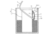
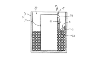
本発明に係る金属線材収納構造体は、図1に示すように、有底円筒状の硬質紙製の外容器1内に、円筒状の硬質紙製の内芯筒2が同心状に配設され、外容器1と内芯筒2との間に円筒状収納空間部30が形成された上方開口箱型の収納容器3に、1本の金属線材Tを、収納空間部30の底部から上方へ向かって、コイル状に巻設しつつ収納している。
Hereinafter, the metal wire storage structure and the metal wire storage method of the present invention will be described in detail based on the illustrated embodiment.
As shown in FIG. 1, the metal wire storage structure according to the present invention has a cylindrical hard paper
収納容器3に収納される長尺(100m以上)の金属線材Tは、具体的には、直径が1.6mm〜3.2mmのハンダ線(亜鉛系合金線、より具体的には、亜鉛とスズを含んだ合金線)である。
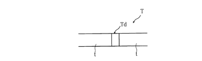
この金属線材Tは、図2に示すように、所定長さ寸法に製造された金属線素材tの端部同士を、直接、突き合わせ融着(溶着)や圧接等の結合手段にて連結し、その後、結合手段にて発生した凸部gを、図3に示すように、研削や磨き等にて削除した(金属線素材tの直径寸法と同等なるように加工した)継目部Tdを少なくとも1箇所に有している。
Specifically, the long (100 m or more) metal wire T stored in the
As shown in FIG. 2, the metal wire T is configured such that the ends of the metal wire material t manufactured to a predetermined length are directly connected by a joining means such as butt fusion (welding) or pressure welding, Thereafter, as shown in FIG. 3, at least one seam Td, which has been removed by grinding, polishing, or the like (processed to be equal to the diameter dimension of the metal wire material t), is generated as the convex portion g generated by the coupling means. Has in place.
ここで、本発明の金属線材収納構造体の説明を容易にするために、金属線材収納構造体の作成工程(金属線材収納方法)と合わせて説明する。
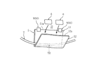
図1に示すように、収納空間部30の下部から金属線材Tをコイル状(平面視渦巻き状)に巻設する。金属線材Tをコイル状に収納していく途中に於て、継目部Tdを収納する際に、図4及び図5に示すように、防湿性樹脂シートを上方開口状(上方開口V字状)に2つ折りした継目保護片5内に、継目部Td及び乾燥剤6を収容し、2つ折りした継目保護片5の一方の第1シート部51を、内芯筒2の外周面21に沿わせ、第2シート部52を第1シート部51よりも内芯筒2のラジアル外方側に配設し、第1シート部51の上縁部51aを固定用粘着テープ91から成る固着手段9にて外周面21に固着している。
なお、図5と、図7乃至図14に於て、固着手段9は図示省略している。
Here, in order to facilitate the description of the metal wire storage structure of the present invention, the metal wire storage structure creation process (metal wire storage method) will be described.
As shown in FIG. 1, the metal wire T is wound in a coil shape (in a spiral shape in a plan view) from the lower part of the
In FIG. 5 and FIGS. 7 to 14, the
そして、図6及び図7に示すように、2つ折りした継目保護片5の他方の第2シート部52の上縁部52aを、仮止め用粘着テープ81から成る仮止め手段8にて、第1シート部51に取着して、保持ユニット(乾燥剤保持ユニット)7を形成している(保持ユニット形成工程)。つまり、第1シート部51の上縁部51aと、継目保護片5の他方の第2シート部52の上縁部52aとが閉状態となるように仮止めする。継目保護片5の両側縁部は開放(開口)状態であり、筒状に形成している。なお、図例では、継目部Tdが1箇所であり、保持ユニット7は1つであるが、継目部Tdが複数箇所ある場合は、夫々に対応するように(数に合わせて)保持ユニット7を形成する。
Then, as shown in FIGS. 6 and 7, the
その後、図8に示すように、金属線材Tで、保持ユニット7の外面72側、言い換えると、第2シート部52の外面側を、内芯筒2側へ押圧しつつ、金属線材Tを収納空間部30に巻設する(保持ユニット押圧工程)。
金属線材Tにて、第2シート部52の上縁部52a乃至中間部(乾燥剤6よりも上方位置)と、第1シート部51が密着状に押圧された状態で、仮止め用粘着テープ81を剥離する(仮止め手段8を解除する)。金属線材Tによる(内芯筒2の軸心を基準軸心として)ラジアル内方の押圧力によって、継目保護片5が上方開口状に展開するのを阻止する。つまり、仮止め用粘着テープ81を剥離しても継目保護片5の2つ折り状態が金属線材Tにて保持可能となってから仮止め用粘着テープ81を剥離する(仮止め手段解除工程)。
なお、仮止め手段8を設けたまま(仮止め用粘着テープ81を貼着したまま)とするも良い。
或いは、仮止め手段8による第2シート部52の仮止めを行わなくても良い。第2シート部52の仮止めを行わない場合は、仮止め手段解除工程は不要であり、図示省略するが、第2シート部52の上縁部52aが、第1シート部51の上縁部51aと同位置、又は、第1シート部51の上縁部51aよりも上方位置となるように配設しておくのが望ましい。
Thereafter, as shown in FIG. 8, the metal wire T is accommodated while pressing the
With the metal wire T, the
Alternatively, the temporary fixing means 8 may be provided (while the temporary
Alternatively, the
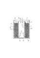
そして、図9に示すように、収納空間部30に、金属線材Tをコイル状に巻設しつつ収納し、防湿性樹脂シートを上方開口状として2つ折りにした継目保護片5内に、継目部Tdと乾燥剤6とを収容した保持ユニット7が、内芯筒2に固着され、さらに、保持ユニット7の外面72側を、巻設したコイル状の金属線材Tにて押圧し、収納容器3を蓋部材4にて施蓋した金属線材収納構造体が作成される(金属線材収納作業が終了する)。
Then, as shown in FIG. 9, the metal wire T is stored in the
次に、本発明の金属線材収納構造体の実施の一形態の使用方法(作用)について説明する。
図9に示すように、2つ折りした継目保護片5の第2シート部52が第1シート部51へ押圧され、継目保護片5内の空気を押し出すと共に、継目保護片5の外部から内部(継目部Tdの周囲)へ空気が浸入するのを抑制する。また、継目保護片5が、防湿性樹脂シートであるため、湿気の浸入を防止する。さらに、乾燥剤6によって、継目保護片5の内部において継目部Td近傍の湿度を極めて(継目保護片5の外部に比べて)低い状態に保持する。
金属線材Tを長期間にわたって保存しても、収納空間部30内の空気の湿気による継目部Tdの酸化が防止され、曲げ強さ(強度)の低下を阻止する。
Next, the usage method (action) of one embodiment of the metal wire storage structure of the present invention will be described.
As shown in FIG. 9, the
Even if the metal wire T is stored for a long period of time, oxidation of the joint Td due to the moisture of the air in the
そして、金属線材Tを、ハンダ付け機械等の産業機械に送るための線材引出装置にて、自動(機械)引き出しすると、保持ユニット7の外面72側に配設されている金属線材Tが引き出されるにつれて、第2シート部52への押圧が解除される。仮止め用粘着テープ81を予め剥離している場合、又は、仮止め手段8を設けていない場合は、押圧が解除されることで、継目保護片5が上方開口状に開く。図10に示すように、金属線材Tの動き(振れ)や、第2シート部52及び乾燥剤6の自重によって、第2シート部52の上縁部52aが第1シート部51から離間して展開し、乾燥剤6が継目部Tdから離間し、金属線材Tのみが引き出される。また、酸化(劣化)が防止された継目部Tdが折損や切断することなくスムーズに引き出される。
つまり、金属線材Tの引き出しに伴って、第2シート部52への押圧が解除されて、2つ折りにした継目保護片5が展開するように構成している。
When the metal wire T is automatically pulled out by a wire drawing device for sending the metal wire T to an industrial machine such as a soldering machine, the metal wire T arranged on the
That is, as the metal wire T is pulled out, the pressing on the
ここで、図示省略するが、仮止め用粘着テープ81を剥離していない場合は、金属線材Tの継目部Tdとその近傍が上方へ引き出される際に、継目部Td及びその近傍が、第1シート部51と第2シート部52の上縁部52aの間で、内芯筒2の軸心廻り(周方向)に移動しつつ上方へ引き出される引き出し力が、仮止め手段8の取着力に抗して(勝って)、仮止め手段8の仮止めを解除する(金属線材Tが仮止め用粘着テープ81に引き出しを阻止されず、金属線材Tが第1シート部51から仮止め用粘着テープ81を剥離する)。金属線材Tの動き(振れ)や、第2シート部52及び乾燥剤6の自重によって、第2シート部52の上縁部52aが第1シート部51から離間して展開し、乾燥剤6が継目部Tdから離間し、金属線材Tのみが引き出される(図10参照)、酸化(劣化)が防止された継目部Tdが折損や切断することなくスムーズに引き出される。
つまり、金属線材Tの継目部Tdとその近傍の上方への引き出しに伴って、仮止め手段8を解除して、第1シート部51と第2シート部52の上縁部52aが離間して、2つ折りにした継目保護片5が展開するように構成している。
Here, although not shown in the drawings, when the
That is, as the joint portion Td of the metal wire T and the vicinity thereof are pulled upward, the temporary fixing means 8 is released, and the
継目保護片5から継目部Tdが引き出された後に、ひき続き金属線材Tが引き出されると、図11に示すように、収納空間部30内の金属線材Tが減少するにつれて、継目保護片5が垂れ下がる(垂れ幕状となる)。また、収納空間部30内に、乾燥剤6が残存する。
When the metal wire T is continuously pulled out after the seam portion Td is pulled out from the
このように、継目保護片5による継目部Tdのサンドイッチ状の包囲及び、乾燥剤6の保持(位置決め)が、自動的に(金属線材Tの引き出しに伴って)解除されるため、作業者が継目保護片5を展開させる作業や、乾燥剤6の除去作業を削減でき、線材引出装置を一時停止させることなく、効率良く、連続的に金属線材Tを引き出すことが可能となる。
Thus, since the sandwich-shaped enclosure of the seam portion Td by the
また、他の実施形態は、図12に示すように、2つ折りした継目保護片5の一方の第1シート部51を、外容器1の内周面11に固着し、第2シート部52を第1シート部51よりも外容器1のラジアル内方側に配設し、図13に示すように、第2シート部52(保持ユニット7の外面72)側を、巻設したコイル状の金属線材Tにて外容器1側へ押圧し、収納容器3を蓋部材4にて施蓋した金属線材収納構造体である。つまり、金属線材Tと外容器1の内周面11で保持ユニット7を挟圧して収納状態において上方開口状となる(展開するのを)阻止している。他の構成及び作用は上述の実施形態と同様である。
In another embodiment, as shown in FIG. 12, one
また、保持ユニット7を外容器1や内芯筒2に固着しなくても良い。上方開口V字状に2つ折りした継目保護片5内に、継目部Td及び乾燥剤6を収容し、V字状の継目保護片5の折曲部(底部)から、巻設されて収納されている金属線材Tと、外容器1又は内芯筒2と、の間に差し込んで、収納状態において展開を阻止するように構成しても良い。
Further, the holding
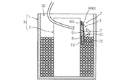
なお、図14に示すように、内芯筒2の下部2bに、内芯筒2の内部と収納空間部30を連通するようにラジアル外方へ開口する複数の通気孔23を設けても良い。
そして、金属線材Tを収納後に、内芯筒2の内部空間に向けて乾燥エア(気体)Kを送り込み、内芯筒2の内部空間の下部から通気孔23を介して収納空間部30の下部へ送流させ、収納空間部30から上方へ排出するように乾燥エアKを送流させて、収納空間部30内の金属線材Tを乾燥させる(乾燥エア送り込み工程)。その後、蓋部材4で施蓋しても良い(図9参照)。収納容器3内(収納空間部30内)の湿気を除去し、蓋部材4を施蓋することで、収納容器3内全体の乾燥状態を保持できる。金属線材T全体の劣化(酸化)を防止できる。
なお、乾燥エア送り込み工程は、収納空間部30に向けて乾燥エアKを送り込み、収納空間部30の下部から通気孔23を介して内芯筒2の内部の下部へ送流させ、内芯筒2の内部から上方へ排出するように、乾燥エアKを送流させても良い。
As shown in FIG. 14, a plurality of vent holes 23 that open radially outward may be provided in the
Then, after storing the metal wire T, dry air (gas) K is sent toward the inner space of the
In the dry air feeding process, the dry air K is fed toward the
なお、本発明は、設計変更可能であって、固着手段9は、接着剤や粘着剤、金属製針等でも良い。仮止め手段8は、粘着剤の塗布等によって形成した粘着層(固着手段9よりも取着力の弱い低粘着層)による仮止めとするも良い。また、図示省略するが、第2シート部52の上縁部52aを、第1シート部51の上縁部51aと同位置になるように仮止めしても良い。或いは、第2シート部52の上縁部52aを、第1シート部51の上縁部51aよりも上方位置となるように外容器1又は内芯筒2に仮止めして閉状態とするも良い。
また、防湿性樹脂シートとは、例えば、OPPフィルムや、PP(ポリプロピレン)樹脂フィルムや、PE(ポリエチレン)樹脂フィルム等、透湿性の低い樹脂シートである。
なお、図面を見易くするために、金属線材T、継目保護片5、乾燥剤6、仮止め手段8を大きくして図示している(図示の各部材同士の比率は、実際の比率と異なる)。
In the present invention, the design can be changed, and the fixing means 9 may be an adhesive, a pressure-sensitive adhesive, a metal needle or the like. The temporary fixing means 8 may be temporarily fixed by an adhesive layer formed by application of an adhesive or the like (a low adhesive layer having a lower adhesive strength than the fixing means 9). Although not shown, the
The moisture-proof resin sheet is a resin sheet having low moisture permeability, such as an OPP film, a PP (polypropylene) resin film, or a PE (polyethylene) resin film.
In addition, in order to make drawing easy to see, the metal wire T, the
以上のように、本発明の金属線材収納構造体は、外容器1と内芯筒2との間に形成された円筒状収納空間部30に、少なくとも1箇所に継目部Tdを有する金属線材Tをコイル状に巻設しつつ収納した金属線材収納構造体に於て、防湿性樹脂シートを上方開口状として2つ折りにした継目保護片5内に、継目部Tdと乾燥剤6とを収容した保持ユニット7が、内芯筒2の外周面21又は外容器1の内周面11に固着され、さらに、保持ユニット7を、巻設したコイル状の金属線材Tにて押圧するように構成したので、継目部Tdを確実かつ容易に長期間にわたって、酸化を防止できる。金属線材Tの収納工程(収納作業)の際に、容易かつ迅速に、酸化(劣化)防止対策を行うことができる。継目部Tdに対して集中的に効率良く酸化防止を行うことができる。特に、ハンダ線のような細く折損や切断しやすい金属線材に好適である。
As described above, the metal wire storage structure of the present invention has a metal wire T having a seam Td at least at one place in the
また、2つ折りにした継目保護片5の一方の第1シート部51の上縁部51aを、内芯筒2の外周面21又は外容器1の内周面11に固着し、金属線材Tの引き出しに伴って、継目保護片5の他方の第2シート部52への押圧が解除されて、2つ折りにした継目保護片5が展開するように構成したので、作業者が継目保護片5を展開させて乾燥剤6を除去する手間や時間を削減でき、連続的にかつ安全に金属線材Tを引き出すことが可能となる。
Further, the
また、2つ折りにした継目保護片5の一方の第1シート部51の上縁部51aを、内芯筒2の外周面21又は外容器1の内周面11に固着し、第1シート部51の上縁部51aと、継目保護片5の他方の第2シート部52の上縁部52aとが閉状態となるように、仮止め手段8にて仮止めし、金属線材Tの継目部Tdとその近傍の上方への引き出しに伴って、仮止め手段8を解除して、第1シート部51の上縁部51aと第2シート部52の上縁部52aが離間して、2つ折りにした継目保護片5が展開するように構成したので、仮止め手段8の解除作業や、作業者が継目保護片5を展開させて、乾燥剤6を除去する手間や時間を削減でき、連続的にかつ安全に金属線材Tを引き出すことが可能となる。
Also, the
1 外容器
2 内芯筒
5 継目保護片
6 乾燥剤
7 保持ユニット
8 仮止め手段
11 内周面
21 外周面
30 収納空間部
51 第1シート部
51a 上縁部
52 第2シート部
52a 上縁部
72 外面
T 金属線材
Td 継目部
DESCRIPTION OF
11 Inner peripheral surface
21 Outer surface
30 Storage space
51 1st sheet part
51a Upper edge
52 Second sheet part
52a Upper edge
72 Outer surface T Metal wire Td Seam
Claims (2)
防湿性樹脂シートを上方開口状として2つ折りにした継目保護片(5)内に上記継目部(Td)と乾燥剤(6)とが収容された保持ユニット(7)が、上記内芯筒(2)の外周面(21)又は上記外容器(1)の内周面(11)に、上記コイル状に収納された上記金属線材(T)にて押圧保持されていることを特徴とする金属線材収納構造体。 Cylindrical housing space portion formed between the outer container (1) and the inner core tube (2) to (30), housed in a metal wire (T) is shaped coil having a seam portion (Td) to at least one location In the metal wire storage structure made,
Folded the seam protecting piece moisture resistance resin sheet as the upper opening shape (5) above Symbol seam portion in the holding unit (Td) and desiccant (6) and is accommodated (7), the inner core tube (2) to the outer peripheral surface (21) or the inner peripheral surface of the outer container (1) (11) of, and characterized by being pressed and held by the metal wire housed in the upper Symbol coiled (T) Metal wire storage structure.
防湿性樹脂シートを上方開口状として2つ折りにした継目保護片(5)内に上記継目部(Td)と乾燥剤(6)とを収容し、上記2つ折りにした継目保護片(5)の一方の第1シート部(51)の上縁部(51a)を、上記内芯筒(2)の外周面(21)又は上記外容器(1)の内周面(11)に固着し、上記第1シート部(51)の上縁部(51a)と、上記継目保護片(5)の他方の第2シート部(52)の上縁部(52a)とが閉状態となるように、仮止め手段(8)にて仮止めして、保持ユニット(7)を形成する保持ユニット形成工程と、The joint portion (Td) and the desiccant (6) are accommodated in a seam protection piece (5) folded in half with the moisture-proof resin sheet as an upper opening, and the seam protection piece (5) folded in half is contained. The upper edge portion (51a) of one first sheet portion (51) is fixed to the outer peripheral surface (21) of the inner core tube (2) or the inner peripheral surface (11) of the outer container (1), and Temporarily so that the upper edge part (51a) of the first sheet part (51) and the upper edge part (52a) of the other second sheet part (52) of the seam protection piece (5) are closed. A holding unit forming step of temporarily holding the holding means (8) to form the holding unit (7);
上記金属線材(T)を上記収納空間部(30)にコイル状に巻設しつつ上記保持ユニット(7)を上記金属線材(T)にて上記外周面(21)又は上記内周面(11)に押圧する保持ユニット押圧工程と、を備え、While the metal wire (T) is wound around the storage space (30) in a coil shape, the holding unit (7) is placed on the metal wire (T) with the outer peripheral surface (21) or the inner peripheral surface (11). And a holding unit pressing step for pressing
上記仮止め手段(8)による仮止めは、上記金属線材(T)の上方への引き出しに伴って仮止めが解除されるように、仮止めすることを特徴とする金属線材収納方法。The metal wire storage method according to claim 1, wherein the temporary fixing by the temporary fixing means (8) is temporarily fixed so that the temporary fixing is released when the metal wire (T) is pulled upward.
Priority Applications (1)
| Application Number | Priority Date | Filing Date | Title |
|---|---|---|---|
| JP2014015797A JP5830552B2 (en) | 2014-01-30 | 2014-01-30 | Metal wire storage structure and metal wire storage method |
Applications Claiming Priority (1)
| Application Number | Priority Date | Filing Date | Title |
|---|---|---|---|
| JP2014015797A JP5830552B2 (en) | 2014-01-30 | 2014-01-30 | Metal wire storage structure and metal wire storage method |
Publications (2)
| Publication Number | Publication Date |
|---|---|
| JP2015140258A JP2015140258A (en) | 2015-08-03 |
| JP5830552B2 true JP5830552B2 (en) | 2015-12-09 |
Family
ID=53770865
Family Applications (1)
| Application Number | Title | Priority Date | Filing Date |
|---|---|---|---|
| JP2014015797A Expired - Fee Related JP5830552B2 (en) | 2014-01-30 | 2014-01-30 | Metal wire storage structure and metal wire storage method |
Country Status (1)
| Country | Link |
|---|---|
| JP (1) | JP5830552B2 (en) |
Families Citing this family (2)
| Publication number | Priority date | Publication date | Assignee | Title |
|---|---|---|---|---|
| PT3326921T (en) * | 2015-07-22 | 2022-09-12 | Max Co Ltd | MOORING MACHINE |
| CN109516310B (en) * | 2018-12-10 | 2024-04-02 | 澳洋集团有限公司 | Far infrared thermal fiber yarn conveying auxiliary device |
Family Cites Families (2)
| Publication number | Priority date | Publication date | Assignee | Title |
|---|---|---|---|---|
| JPS6115270U (en) * | 1984-06-30 | 1986-01-29 | 昭和電線電纜株式会社 | Pail pack for wire rod |
| JPS6115271U (en) * | 1984-06-30 | 1986-01-29 | 昭和電線電纜株式会社 | Pail pack for wire rod |
-
2014
- 2014-01-30 JP JP2014015797A patent/JP5830552B2/en not_active Expired - Fee Related
Also Published As
| Publication number | Publication date |
|---|---|
| JP2015140258A (en) | 2015-08-03 |
Similar Documents
| Publication | Publication Date | Title |
|---|---|---|
| JP5830552B2 (en) | Metal wire storage structure and metal wire storage method | |
| EP0052111A1 (en) | Method for producing a package. | |
| WO2008070383A1 (en) | Over-wrap apparatus and method for a bobbin and paper | |
| KR101648212B1 (en) | Box | |
| JP2014051312A (en) | Packing bag and packing bag bundle body | |
| JP2015054761A (en) | Cutoff type bag tape, bag roll, and method for using the bag roll | |
| KR101747961B1 (en) | Air filter cartridge and assembly method thereof | |
| JP6713311B2 (en) | Method of attaching and detaching inner bag and inner bag used in the method | |
| JP6117172B2 (en) | Manufacturing method of wire harness | |
| FR2882039A1 (en) | OBLIQUE INTERNAL WALL CONTAINER FOR CONDITIONING WELDING WIRE | |
| JP2015139311A (en) | Electric wire module and corrugated tube with elastic member | |
| US9999936B2 (en) | Solder wire bobbinless coil | |
| JP4856568B2 (en) | Bladder insertion method of accumulator | |
| JP5025429B2 (en) | Packaging container | |
| EP4534441A1 (en) | Packaging system for rolled-up sheet material, apparatus and method using it | |
| JP4498832B2 (en) | Shrink wrapping material, shrink wrapping material manufacturing method and shrink wrapping material manufacturing apparatus | |
| US10632407B2 (en) | Method and device for arranging a gas filter on a component of a recipient | |
| JP5605756B2 (en) | Packing box closure | |
| JP6293493B2 (en) | Adhesive sheet | |
| JP5095471B2 (en) | Packaging container and blank sheet | |
| KR20080006328U (en) | Cake Support Plate | |
| WO2015170378A1 (en) | Device for forming seal-rupture part in package, and pressure-sensitive adhesive tape for seal-rupture | |
| JP6134229B2 (en) | Wrapping film storage box and method for manufacturing wrapping film storage box | |
| WO2008050872A1 (en) | Box body | |
| JP2009061214A (en) | Ball protective device |
Legal Events
| Date | Code | Title | Description |
|---|---|---|---|
| A131 | Notification of reasons for refusal |
Free format text: JAPANESE INTERMEDIATE CODE: A131 Effective date: 20150804 |
|
| A521 | Request for written amendment filed |
Free format text: JAPANESE INTERMEDIATE CODE: A523 Effective date: 20150917 |
|
| TRDD | Decision of grant or rejection written | ||
| A01 | Written decision to grant a patent or to grant a registration (utility model) |
Free format text: JAPANESE INTERMEDIATE CODE: A01 Effective date: 20151020 |
|
| A61 | First payment of annual fees (during grant procedure) |
Free format text: JAPANESE INTERMEDIATE CODE: A61 Effective date: 20151026 |
|
| R150 | Certificate of patent or registration of utility model |
Ref document number: 5830552 Country of ref document: JP Free format text: JAPANESE INTERMEDIATE CODE: R150 |
|
| R250 | Receipt of annual fees |
Free format text: JAPANESE INTERMEDIATE CODE: R250 |
|
| R250 | Receipt of annual fees |
Free format text: JAPANESE INTERMEDIATE CODE: R250 |
|
| LAPS | Cancellation because of no payment of annual fees |