JP5828639B2 - Gasket for prefilled syringe, method for producing the same, and prefilled syringe - Google Patents
Gasket for prefilled syringe, method for producing the same, and prefilled syringe Download PDFInfo
- Publication number
- JP5828639B2 JP5828639B2 JP2011007360A JP2011007360A JP5828639B2 JP 5828639 B2 JP5828639 B2 JP 5828639B2 JP 2011007360 A JP2011007360 A JP 2011007360A JP 2011007360 A JP2011007360 A JP 2011007360A JP 5828639 B2 JP5828639 B2 JP 5828639B2
- Authority
- JP
- Japan
- Prior art keywords
- gasket
- prefilled
- manufacturing
- liquid contact
- sliding
- Prior art date
- Legal status (The legal status is an assumption and is not a legal conclusion. Google has not performed a legal analysis and makes no representation as to the accuracy of the status listed.)
- Active
Links
Images


Description
本発明は、プレフィルドシリンジ用ガスケット、その製造方法、及び該ガスケットを有するプレフィルドシリンジに関する。 The present invention relates to a gasket for a prefilled syringe, a manufacturing method thereof, and a prefilled syringe having the gasket.
近年では、使用時の簡便性に優れ、かつ薬剤の取り違えなどの医療事故を防止できるという点から、予め薬液を注射器に充填したプレフィルドシリンジの使用が拡大している(特許文献1参照)。プレフィルドシリンジは、注射針が取り付けられる先端部分がキャップで密閉されており、投与の際には先端部分に注射針を取り付け、プランジャーロッドを先端側に向けて押し込んでガスケットを摺動させることにより、注射針を介して注射液が投与される。 In recent years, the use of prefilled syringes in which a liquid medicine is preliminarily filled with a syringe has been expanded from the viewpoint that it is excellent in convenience during use and can prevent medical accidents such as mixing of medicines (see Patent Document 1). In the prefilled syringe, the tip part to which the injection needle is attached is sealed with a cap. At the time of administration, the injection needle is attached to the tip part, and the plunger rod is pushed toward the tip side to slide the gasket An injection solution is administered through an injection needle.
ガスケットの表面にフッ素樹脂などの不活性フィルムを積層(ラミネート)することにより、耐薬品性を向上させることができる。しかし、不活性フィルムを積層すると、弾性が低下して気密性が悪化するため、薬液が漏れてしまうおそれがある。従って、耐薬品性及び気密性を両立したガスケットの開発が求められている。 The chemical resistance can be improved by laminating (laminating) an inert film such as a fluororesin on the surface of the gasket. However, when an inert film is laminated, the elasticity is lowered and the airtightness is deteriorated, so that the chemical solution may leak. Therefore, there is a demand for the development of a gasket that achieves both chemical resistance and airtightness.
本発明は、前記課題を解決し、耐薬品性及び気密性を両立できるプレフィルドシリンジ用ガスケット、その製造方法、及びプレフィルドシリンジを提供することを目的とする。 An object of the present invention is to solve the above-mentioned problems and to provide a gasket for a prefilled syringe that can achieve both chemical resistance and airtightness, a manufacturing method thereof, and a prefilled syringe.
本発明は、接液部と、環状突起を有する摺動部とを備えるプレフィルドシリンジ用ガスケットであって、上記接液部は、不活性フィルムが積層され、上記摺動部は、不活性フィルムが積層されていないプレフィルドシリンジ用ガスケットに関する。 The present invention is a prefilled syringe gasket comprising a wetted part and a sliding part having an annular projection, wherein the wetted part is laminated with an inert film, and the sliding part is made of an inert film. The present invention relates to a gasket for prefilled syringes that is not laminated.
上記接液部は凸部を有することが好ましい。 The liquid contact part preferably has a convex part.
上記接液部は平坦部及び/又は傾斜部を端部に有することが好ましい。 The liquid contact part preferably has a flat part and / or an inclined part at the end.
上記接液部の端部と上記摺動部とがなす角度は90〜110度であることが好ましい。 The angle formed by the end of the liquid contact part and the sliding part is preferably 90 to 110 degrees.
上記接液部は中心から端部に向かって傾斜部及び平坦部をこの順に有することが好ましい。 The liquid contact part preferably has an inclined part and a flat part in this order from the center toward the end part.
上記接液部は中心から端部に向かって多段階の傾斜部を有することが好ましい。 The liquid contact part preferably has a multi-step inclined part from the center toward the end part.
上記接液部は中心から端部に向かって平坦部及び傾斜部をこの順に有することが好ましい。 The liquid contact part preferably has a flat part and an inclined part in this order from the center toward the end part.
上記不活性フィルムは、テトラフルオロエチレン・エチレン共重合体、変性テトラフルオロエチレン・エチレン共重合体及びポリクロロテトラフルオロエチレンからなる群より選択される少なくとも1種のフッ素樹脂、及び/又はオレフィン系樹脂であることが好ましい。 The inert film includes at least one fluororesin selected from the group consisting of a tetrafluoroethylene / ethylene copolymer, a modified tetrafluoroethylene / ethylene copolymer, and polychlorotetrafluoroethylene, and / or an olefin resin. It is preferable that
不活性フィルムが積層された部分は、磨き加工によって中心線表面粗さRaが1.0μm以下に調整されており、上記摺動部は、研磨剤を用いたブラスト加工によって中心線表面粗さRaが1.5〜3.5μmに調整されていることが好ましい。 In the portion where the inert film is laminated, the centerline surface roughness Ra is adjusted to 1.0 μm or less by polishing, and the sliding portion has a centerline surface roughness Ra by blasting using an abrasive. Is preferably adjusted to 1.5 to 3.5 μm.
本発明はまた、未加硫のゴムシートと上記不活性フィルムとを重ねて成形金型に置き、真空プレスで加熱圧縮し、上記接液部と上記摺動部とを備える複数の上記プレフィルドシリンジ用ガスケットが成形された成形シートを得る工程、上記成形シートの摺動部側にシリコーンを塗布する工程、シリコーンが塗布された上記成形シートの摺動部を打ち抜き型の下刃にセットし、上記成形シートの接液部側からストリッパープレートを下降させ、上記成形シートのバリ部にテンションを掛ける工程、及び上記成形シートの接液部側から上刃を下降させ、上記環状突起と略同径に上記バリ部を切断し、第一環状突起部が形成される工程をこの順に含む上記ガスケットの製造方法に関する。 The present invention also provides a plurality of the prefilled syringes comprising the unvulcanized rubber sheet and the inert film, which are placed on a molding die, heated and compressed by a vacuum press, and the liquid contact part and the sliding part. A step of obtaining a molded sheet in which a gasket for molding is formed, a step of applying silicone to the sliding portion side of the molded sheet, a sliding portion of the molded sheet coated with silicone is set on the lower blade of the punching die, and Lowering the stripper plate from the wetted part side of the molded sheet and applying tension to the burr part of the molded sheet; and lowering the upper blade from the wetted part side of the molded sheet so as to have substantially the same diameter as the annular protrusion It is related with the manufacturing method of the said gasket which cut | disconnects the said burr | flash part and includes the process in which a 1st annular projection part is formed in this order.
上記成形シートの切断部の厚みが0.5〜1.5mmであることが好ましい。 The thickness of the cut portion of the molded sheet is preferably 0.5 to 1.5 mm.
上記上刃の厚みが0.5〜2.0mmであることが好ましい。 It is preferable that the thickness of the upper blade is 0.5 to 2.0 mm.
本発明はまた、上記ガスケットを有するプレフィルドシリンジに関する。 The present invention also relates to a prefilled syringe having the gasket.
本発明によれば、接液部と、環状突起を有する摺動部とを備えるプレフィルドシリンジ用ガスケットであって、上記接液部は、不活性フィルムが積層され、上記摺動部は、不活性フィルムが積層されていないプレフィルドシリンジ用ガスケット、その製造方法、及びプレフィルドシリンジであるので、耐薬品性及び気密性を両立できる。 According to the present invention, there is provided a gasket for a prefilled syringe comprising a wetted part and a sliding part having an annular projection, wherein the wetted part is laminated with an inert film, and the sliding part is inactive. Since it is the gasket for prefilled syringes which the film is not laminated | stacked, its manufacturing method, and a prefilled syringe, it can be compatible in chemical resistance and airtightness.
以下に実施形態を掲げ、本発明を詳細に説明するが、本発明はこれらの実施形態のみに限定されるものではない。 The present invention will be described in detail below with reference to embodiments, but the present invention is not limited only to these embodiments.
(実施形態1)
図1は、実施形態1のガスケットを示す断面模式図である。
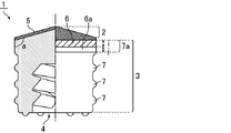
図1において、ガスケット(プレフィルドシリンジ用ガスケット)1は、シリンジ内で薬液に接触し、摺動時にシリンジ内壁に接触しない接液部2と、摺動時にシリンジ内壁と接触する摺動部(環状シール部)3と、プランジャーロッドが嵌合される嵌合穴4とを有する。
(Embodiment 1)
FIG. 1 is a schematic cross-sectional view showing the gasket of the first embodiment.
In FIG. 1, a gasket (prefilled syringe gasket) 1 is in contact with a chemical solution in a syringe and does not contact the syringe inner wall during sliding, and a sliding portion (annular seal) that contacts the syringe inner wall during sliding. Part) 3 and a
接液部2には不活性フィルム5が積層されており、図1では凸部を有する接液部2の一例が示されている。この不活性フィルム5は、接液部2に積層され、摺動部3には積層されていない。不活性フィルム5をこのように配置することにより、ガスケット1の耐薬品性を向上させながら、良好な気密性を確保することができる。
An
不活性フィルム5としては特に限定されないが、良好な耐薬品性が得られるという点から、テトラフルオロエチレン・エチレン共重合体(ETFE)、ポリテトラフルオロエチレン(PTFE)、ポリクロロテトラフルオロエチレン(PCTFE)からなる群より選択される少なくとも1種のフッ素樹脂、及び/又はオレフィン系樹脂が好ましい。また、医療用容器の滅菌法として、蒸気滅菌、エチレンオキサイドガス滅菌、ガンマ線滅菌が行われるが、PTFEはガンマ線に対する耐性が低い。よって、ガンマ線滅菌に対する耐性が高いETFE、変性ETFE、PCTFEが特に好ましい。
Although it does not specifically limit as the
ETFE、変性ETFE及びPTFEのガンマ−線滅菌後の物性を表1に示す。 Table 1 shows the physical properties of ETFE, modified ETFE and PTFE after gamma-ray sterilization.

変性ETFEとしては、接着性を付与する官能基を有するETFEを好適に使用することができ、該官能基としては、カルボキシル基、無水カルボキシル基、エポキシ基、水酸基、イソシアネート基、エステル基、アミド基、アルデヒド基、アミノ基、シアノ基、炭素−炭素二重結合、スルホン酸基、エーテル基などが挙げられる。また、変性ETFEの市販品としては、旭硝子(株)製のフルオンAH−2000などが挙げられる。 As the modified ETFE, ETFE having a functional group imparting adhesiveness can be suitably used. Examples of the functional group include a carboxyl group, an anhydrous carboxyl group, an epoxy group, a hydroxyl group, an isocyanate group, an ester group, and an amide group. Aldehyde group, amino group, cyano group, carbon-carbon double bond, sulfonic acid group, ether group and the like. Moreover, as a commercial item of modified ETFE, Asahi Glass Co., Ltd. full-on AH-2000 etc. are mentioned.
オレフィン系樹脂としては、ポリエチレン、エチレン−プロピレン共重合体、エチレン−プロピレン−非共役ジエン共重合体、エチレン−ブテン共重合体、エチレン−ヘキセン共重合体、エチレン−オクテン共重合体、エチレン−酢酸ビニル共重合体、エチレン−ビニルアルコール共重合体、エチレン−エチルアクリレート共重合体、塩素化ポリエチレン等のポリエチレン系樹脂、ポリプロピレン、プロピレン−エチレンランダム共重合体、プロピレン−エチレンブロック共重合体、塩素化ポリプロピレン等のポリプロピレン系樹脂、ポリブテン、ポリイソブチレン、ポリメチルペンテン、環状オレフィンの共重合体等が挙げられ、ポリエチレン(特に超高分子量ポリエチレン(UHMWPE))が好ましい。また、オレフィン系樹脂は、フッ素を含んでいてもよい。 Examples of the olefin resin include polyethylene, ethylene-propylene copolymer, ethylene-propylene-nonconjugated diene copolymer, ethylene-butene copolymer, ethylene-hexene copolymer, ethylene-octene copolymer, ethylene-acetic acid. Vinyl copolymers, ethylene-vinyl alcohol copolymers, ethylene-ethyl acrylate copolymers, polyethylene resins such as chlorinated polyethylene, polypropylene, propylene-ethylene random copolymers, propylene-ethylene block copolymers, chlorinated Examples thereof include polypropylene resins such as polypropylene, polybutene, polyisobutylene, polymethylpentene, and cyclic olefin copolymers, and polyethylene (particularly, ultrahigh molecular weight polyethylene (UHMWPE)) is preferable. The olefin resin may contain fluorine.
不活性フィルム5の厚みはガスケット1の形状やサイズに合わせて適宜調整すればよいが、50〜200μmであることが好ましい。
The thickness of the
不活性フィルム5は、ゴム等との接着性を高める処理を行うことが好ましい。接着性を高める処理としては、化学処理法、フィルムの表面を粗面化する処理や、これらを組み合わせたものが挙げられ、具体例としては、ナトリウム処理、グロー放電処理、大気圧下又は真空下でのプラズマ処理(放電処理)、エキシマレーザー処理(放電処理)、イオンビーム処理が挙げられる。
The
摺動部3の環状突起数は特に限定されないが、2〜4であることが好ましい。摺動部3は、切断部6、又は切断部6及び金型成形部6aよりなる第一環状突起部7aと、複数の環状突起7とを有する。なお、摺動部3は金型成形部6aを有していなくてもよい。摺動抵抗を低減できるという点から、摺動部3は、シリコーンコート等の潤滑剤をコートすることが好ましい。なお、潤滑剤は摺動部3の全てにコートする必要はなく、例えば、切断部6がコートされていなくてもよい。
The number of annular protrusions of the sliding
不活性フィルム5が積層された接液部2で薬剤との接触を防止し、接液部2側から連続する切断部6、又は該切断部6及び金型成形部6aよりなる第一環状突起部と、環状突起7とによりシリンジ内が隔てられることにより気密性、液密性が保たれるが、特に切断部6、又は切断部6及び金型成形部6aよりなる第一環状突起部が重要である。
The first annular protrusion comprising the cutting
切断部6の厚みは0.5〜1.5mmであることが好ましく、金型成形部6aの厚みは0〜1.0mmが好ましい。切断部6の厚みは大きくなるほど摺動抵抗が大きくなり、1.5mmを超えると、実用的ではない。一方0.5mm未満であると、十分な気密性、液密性を確保できないおそれがある。また、切断部6の厚みが上記範囲内であれば、ガスケット1の製造時に金型から成形シートを容易に取り剥がすことができる。
なお、切断部6の厚みは、図1中の上下方向の長さiであり、金型成形部6aの厚みは、図1中の上下方向の長さjである。
The thickness of the cutting
The thickness of the cutting
シリンジ内壁やガスケット1先端の接液部2に気泡が付着し易いという問題があり、気泡が付着した状態で薬液を投与すると、薬剤と同時に血管内に混入し、空気塞栓等を起こす場合がある。通常、気泡が付着した場合、投与前にシリンジノズルを上方に向けて、シリンジ胴部を指ではじいて気泡をノズル先端に集めて排出して投与するが、迅速な対応が求められる医療現場では対応が困難であり、特に、ガスケット1先端の接液部2に付着した気泡は抜けにくいという問題がある。上記気泡は薬剤の粘度によって付着し易い場合があり、また、接液部2の表面が粗いほど気泡が付着し易い。よって、接液部2の気泡の付着を防止できるという点から、不活性フィルム5が積層された部分は、磨き加工によって中心線表面粗さRaが1.0μm以下に調整されていることが好ましい。
なお、中心線表面粗さRaは、JIS B0601−2001で規定される値である。
There is a problem that bubbles easily adhere to the inner wall of the syringe or the
The centerline surface roughness Ra is a value defined by JIS B0601-2001.
摺動部3は、研磨材を用いたブラスト加工によって中心線表面粗さRaが1.5〜3.5μmに調整されていることが好ましい。上記範囲内であれば、良好な摺動性、気密性、液密性及び固着性が得られる。研磨材はJIS R6001−1998で規定される♯46〜100を使用することが好ましい。
The sliding
接液部2の端部と摺動部3とがなす角度aは90〜110度であることが好ましい。通常、シリンジ内の先端部は、円筒形(図12)や、先端に向かって細くなる円錐形(図13)であるため、接液部2の端部と摺動部3とがなす角度aを上記範囲内とすることにより、シリンジ内の薬液を効率よく押し出すことができる。角度aは、好ましくは108度以下、より好ましくは106度以下、更に好ましくは105度以下、特に好ましくは104度以下である。
The angle a formed by the end of the
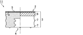
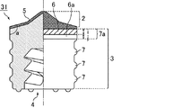
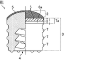
なお、本実施形態では、接液部2が先端に向かって凸状である場合を示しているが、接液部2の形状はこれに限定されず、他の形状であってもよく、例えば、平坦部及び/又は傾斜部を端部に有する形状であってもよい。図2は、接液部が平坦部を有する例であり、図3は、接液部2が中心から端部に向かって傾斜部及び平坦部をこの順に有する例であり、図4は接液部2が中心から端部に向かって多段階の傾斜部を有する例であり、図5は、接液部2が中心から端部に向かって平坦部及び傾斜部をこの順に有する例である。
In addition, in this embodiment, although the case where the liquid-
また、本実施形態では、接液部2の端部が直線状(傾斜部又は平坦部)である場合を示しているが、接液部2の端部は曲線状であってもよい。図14は、接液部2が中心から端部に向かって傾斜部及び曲線部をこの順に有する例である。図14において、角度aは、接液部2の最も摺動部3側の傾斜部又は平坦部と、摺動方向に沿った直線とがなす角度である。また、図15は、接液部2が曲線部のみで構成された例(傾斜部及び平坦部を有しない例)である。
Moreover, although the case where the edge part of the liquid-
以下、実施形態1のガスケットの製造方法について説明する。
図6及び7は、実施形態1のガスケットの製造工程(打ち抜き工程)を示す断面模式図である。
Hereinafter, the manufacturing method of the gasket of Embodiment 1 is demonstrated.
6 and 7 are schematic cross-sectional views illustrating the manufacturing process (punching process) of the gasket of the first embodiment.
まず、不活性フィルム5と未加硫のゴムシート104とを重ねて成形金型に置き、真空プレスで加熱圧縮を行う。加熱圧縮により、不活性フィルム5と未加硫のゴムシート104との加硫接着、及び成形が行われる。これにより、ガスケット1の形状、及び偏芯防止用リング106がそれぞれ複数成形された成形シート105が得られる。なお、ガスケット1には、接液部と、環状突起部を有する摺動部とが成形される。
First, the
ゴムシート104としては、合成ゴム及び熱可塑性エラストマーを使用することができる。なかでも、良好な気密性が得られるという点から、合成ゴムが好ましく、ブチルゴムがより好ましい。ブチルゴムとしては、塩素化ブチルゴムなどのハロゲン化ブチルゴムを好適に使用できる。
As the
成形後、成形シート105の摺動部側にシリコーンを塗布する。シリコーンの塗布は、成形シート105のゴムシート104側(摺動部が成形された側)から行うことが好ましい。これにより、接液部にシリコーンが付着しないため、シリコーンによる薬液の汚染を防止できる。
After molding, silicone is applied to the sliding portion side of the molded
次に、図6に示すように、成形シート105の摺動部を打ち抜き型の下刃101にセットする。その後、偏芯抜き不良をなくすため、図7に示すように、成形シート105の接液部側からストリッパープレート102を下降させ、成形シート105のバリ部にテンションを掛け、成形シート105を下刃101に密着させる。
Next, as shown in FIG. 6, the sliding portion of the molded
この状態で、成形シート105の接液部側から上刃103を下降させ、環状突起と略同径に成形シート105のバリ部を切断することで、切断部、又は切断部及び金型成形部からなる第一環状突起部が形成される。これにより、ガスケット1が得られる。
In this state, the
図8、図9に示す従来例は、成形シート205の向きを上述の製造方法とは逆にした方法であり、この方法では、上刃203が下降すると上刃203のテーパー状内に空間ネジ部を圧縮した状態で摺動部が入るため、刃材質との擦れにより汚れ不良が発生する。また、上刃203の切断時の摩耗により研磨メンテナンスが必要となり、研磨によって刃厚が大きくなると、上述の問題が発生しやすく、上刃203内面の加工も必要となる。これに対し、上述の製造方法では、接液部が成形された側から成形シート105を切断しているため、これらの問題を解消することができる。
The conventional example shown in FIGS. 8 and 9 is a method in which the direction of the molded
接液部の端部と摺動部とがなす角度aが大きい場合、ストリッパープレート102が成形シート105にテンションを掛ける前に上刃103が成形シート105と接触し、所望の位置で成形シート105を切断できなくなり、寸法不良が発生する場合がある。従って、上記寸法不良の発生を防止するため、接液部の端部と摺動部とがなす角度aを90〜110度の範囲内に調整することが好ましい。
When the angle a formed by the end of the liquid contact portion and the sliding portion is large, the
上刃103の先端部(成形シート105と接触する部分)の厚みhは、0.5〜2.0mmであることが好ましい。上記範囲内であれば、成形シート105を所望の位置で容易に切断できる。
The thickness h of the tip portion of the upper blade 103 (the portion in contact with the molded sheet 105) is preferably 0.5 to 2.0 mm. Within the above range, the molded
以下、実施例に基づいて本発明を具体的に説明するが、本発明はこれらのみに限定されるものではない。 EXAMPLES Hereinafter, although this invention is demonstrated concretely based on an Example, this invention is not limited only to these.
実施例及び比較例
塩素化ブチルゴムを含む未加硫のゴムシートと厚み100μmの不活性フィルムとを張り合わせ、真空プレスで175℃、10分間加硫接着しながら成形し、ガスケットの形状、及び偏芯防止用リングがそれぞれ複数成形された成形シートを得た。得られた成形シートのゴムシート側(摺動部が成形された側)をシリコーンでコートした後、図6及び7で示した方法で成形シートを打ち抜き、図1〜5、及び図10〜11に示す形状のガスケットを得た。使用した上刃の先端部の厚みは1.2mm、成形シートの切断部の厚みは1.0mmであった。得られたガスケットを洗浄、滅菌乾燥してから、該ガスケットを用いてプレフィルドシリンジ(公称容量:5ml、シリンジ内径:12.45mm)を作製し、以下の試験を行った。
Examples and Comparative Examples An unvulcanized rubber sheet containing chlorinated butyl rubber and an inactive film having a thickness of 100 μm were laminated together, and molded while vulcanizing and bonding at 175 ° C. for 10 minutes in a vacuum press, and the shape and eccentricity of the gasket A molded sheet was obtained in which a plurality of prevention rings were molded. After coating the rubber sheet side (side on which the sliding portion is formed) of the obtained molded sheet with silicone, the molded sheet is punched out by the method shown in FIGS. 6 and 7, and FIGS. 1 to 5 and FIGS. A gasket having the shape shown in FIG. The thickness of the tip part of the used upper blade was 1.2 mm, and the thickness of the cut part of the molded sheet was 1.0 mm. After the obtained gasket was washed and sterilized and dried, a prefilled syringe (nominal capacity: 5 ml, syringe inner diameter: 12.45 mm) was prepared using the gasket, and the following tests were performed.
(圧力試験)
十分水をふき取った注射筒に、公称容量目盛りの3/4、公称容量目盛りの1/2の位置まで水を吸い入れ、これを水平に固定して水が筒口から出ないようにした後、筒口に343kPaの圧力を10秒間加え、はめ合わせ部から水滴が落ちないことを確認した。結果は、「水滴が落ちた本数/試験本数」で表記した。
(Pressure test)
After sucking water into the syringe barrel that has sufficiently wiped water to 3/4 of the nominal volume scale and 1/2 of the nominal volume scale, and fixing it horizontally to prevent water from coming out of the barrel mouth, A pressure of 343 kPa was applied to the tube opening for 10 seconds, and it was confirmed that water droplets did not fall from the fitting portion. The result was expressed as “number of water drops dropped / number of tests”.
(吸引試験)
注射筒の公称容量目盛りの1/4の位置まで水を吸い入れ、筒口を密封した後、押し子を公称容量目盛りの位置まで引いたとき、はめ合わせ部から連続した気泡が発生しないことを確認した。結果は、「連続した気泡が発生した本数/試験本数」で表記した。
(Suction test)
After sucking water up to 1/4 of the nominal volume scale of the syringe barrel and sealing the tube mouth, when the pusher is pulled to the nominal volume scale position, it is confirmed that no continuous bubbles are generated from the fitting section did. The result was expressed as “number of continuous bubbles generated / number of tests”.
(蒸気滅菌後の漏れ)
上記プレフィルドシリンジを125℃で40分間蒸気滅菌し、冷却後、ガスケットの環状突起部間の凹部への漏れを目視で確認した。結果は、「凹部への漏れが発生した本数/試験本数」で表記した。
(Leakage after steam sterilization)
The prefilled syringe was steam sterilized at 125 ° C. for 40 minutes, and after cooling, leakage into the recesses between the annular projections of the gasket was visually confirmed. The results were expressed as “number of leaks in the recess / number of tests”.
比較例1及び3は、不活性フィルムが積層されていないため、薬液の種類によっては使用できない場合がある。 Since the inactive film is not laminated | stacked, the comparative examples 1 and 3 may be unable to be used depending on the kind of chemical | medical solution.
比較例2及び4は、接液部及び摺動部の両方に不活性フィルムが積層されているため、気密性が低かった。特に、内径バラツキが大きいガラス製のシリンジの場合、液漏れなどが発生しやすい傾向があった。 In Comparative Examples 2 and 4, since the inert film was laminated on both the liquid contact part and the sliding part, the airtightness was low. In particular, in the case of a glass syringe with large inner diameter variation, there was a tendency that liquid leakage or the like was likely to occur.
実施例1〜10では、液漏れなどが発生しておらず、耐薬品性及び気密性を両立できた。なお、実施例1及び5は、ガンマ線に対する耐性が低いPTFEを不活性フィルムとして使用しているため、ガンマ線滅菌を行うことができないが、実施例2〜5、及び実施例7〜10は、ガンマ線に対する耐性が高いETFEを不活性フィルムとして使用しているため、ガンマ線滅菌を行うことができる。 In Examples 1 to 10, no liquid leakage occurred, and both chemical resistance and airtightness could be achieved. In addition, although Examples 1 and 5 use PTFE having low resistance to gamma rays as an inert film, gamma ray sterilization cannot be performed, but Examples 2 to 5 and Examples 7 to 10 are gamma rays. Since ETFE, which has high resistance to ceramide, is used as an inert film, gamma sterilization can be performed.
1、11、21、31、41、51、61、71、81、91 ガスケット(プレフィルドシリンジ用ガスケット)
2 接液部
3 摺動部(環状シール部)
4 嵌合穴
5、15 不活性フィルム
6 切断部
6a 金型成形部
7 環状突起
7a 第一環状突起部
101、201 下刃
102、202 ストリッパープレート
103、203 上刃
104、204 ゴムシート
105、205 成形シート
106 偏芯防止用リング
1, 11, 21, 31, 41, 51, 61, 71, 81, 91 Gasket (gasket for prefilled syringe)
2
4 Fitting
Claims (9)
前記接液部は、不活性フィルムが積層され、
前記摺動部は、不活性フィルムが積層されておらず、
前記接液部が平坦部及び/又は傾斜部を端部に有し、前記接液部の端部と前記摺動部とがなす角度が90〜110度であるプレフィルドシリンジ用ガスケットを製造する方法であって、
該製造方法は、未加硫のゴムシートと前記不活性フィルムとを重ねて成形し、前記接液部と前記摺動部とを備える前記プレフィルドシリンジ用ガスケットが成形された成形シートを得る工程、
前記成形シートの摺動部を打ち抜き型の下刃にセットする工程、及び
前記成形シートの接液部側から上刃を下降させ、前記成形シートを切断する工程をこの順に含むプレフィルドシリンジ用ガスケットの製造方法。 It has a wetted part and a sliding part having an annular protrusion,
The liquid contact part is laminated with an inert film,
The sliding part is not laminated with an inert film,
A method for producing a gasket for a prefilled syringe , wherein the liquid contact part has a flat part and / or an inclined part at an end part, and an angle formed by the end part of the liquid contact part and the sliding part is 90 to 110 degrees. Because
The manufacturing method includes a step of obtaining a molded sheet in which the unfilled rubber sheet and the inert film are stacked and molded, and the prefilled syringe gasket including the liquid contact portion and the sliding portion is formed;
A step of setting the sliding portion of the molded sheet on the lower blade of the punching die; and
The manufacturing method of the gasket for prefilled syringes which includes the process of dropping the upper blade from the liquid-contact part side of the said molded sheet, and cut | disconnecting the said molded sheet in this order .
前記摺動部は、研磨剤を用いたブラスト加工によって中心線表面粗さRaが1.5〜3.5μmに調整されている請求項1〜6のいずれかに記載のプレフィルドシリンジ用ガスケットの製造方法。 The portion where the inert film is laminated has a center line surface roughness Ra adjusted to 1.0 μm or less by polishing,
The manufacturing of the gasket for a prefilled syringe according to any one of claims 1 to 6 , wherein the sliding portion has a centerline surface roughness Ra adjusted to 1.5 to 3.5 µm by blasting using an abrasive. Method.
Priority Applications (1)
| Application Number | Priority Date | Filing Date | Title |
|---|---|---|---|
| JP2011007360A JP5828639B2 (en) | 2011-01-17 | 2011-01-17 | Gasket for prefilled syringe, method for producing the same, and prefilled syringe |
Applications Claiming Priority (1)
| Application Number | Priority Date | Filing Date | Title |
|---|---|---|---|
| JP2011007360A JP5828639B2 (en) | 2011-01-17 | 2011-01-17 | Gasket for prefilled syringe, method for producing the same, and prefilled syringe |
Related Child Applications (1)
| Application Number | Title | Priority Date | Filing Date |
|---|---|---|---|
| JP2015159043A Division JP2015226841A (en) | 2015-08-11 | 2015-08-11 | Gasket for prefilled syringe, production method thereof and prefilled syringe |
Publications (3)
| Publication Number | Publication Date |
|---|---|
| JP2012147859A JP2012147859A (en) | 2012-08-09 |
| JP2012147859A5 JP2012147859A5 (en) | 2012-10-11 |
| JP5828639B2 true JP5828639B2 (en) | 2015-12-09 |
Family
ID=46790769
Family Applications (1)
| Application Number | Title | Priority Date | Filing Date |
|---|---|---|---|
| JP2011007360A Active JP5828639B2 (en) | 2011-01-17 | 2011-01-17 | Gasket for prefilled syringe, method for producing the same, and prefilled syringe |
Country Status (1)
| Country | Link |
|---|---|
| JP (1) | JP5828639B2 (en) |
Families Citing this family (15)
| Publication number | Priority date | Publication date | Assignee | Title |
|---|---|---|---|---|
| JP6077861B2 (en) * | 2013-01-17 | 2017-02-08 | 住友ゴム工業株式会社 | Sliding elastic body |
| JP2014223149A (en) * | 2013-05-15 | 2014-12-04 | 住友ゴム工業株式会社 | Gasket for syringe |
| JP6199604B2 (en) | 2013-05-15 | 2017-09-20 | 住友ゴム工業株式会社 | Medical gasket |
| JP6297803B2 (en) * | 2013-08-27 | 2018-03-20 | 住友ゴム工業株式会社 | Gasket for syringe |
| FR3011472B1 (en) * | 2013-10-09 | 2017-09-01 | Aptar Stelmi Sas | CAP-PISTON AND SYRINGE DEVICE COMPRISING SUCH A PLUG-PISTON |
| JP5947823B2 (en) * | 2014-01-29 | 2016-07-06 | 住友ゴム工業株式会社 | Manufacturing method of medical gasket |
| JP2015195813A (en) | 2014-03-31 | 2015-11-09 | 住友ゴム工業株式会社 | Gasket for prefilled syringe and manufacturing method thereof |
| JP6403257B2 (en) * | 2014-07-23 | 2018-10-10 | 住友ゴム工業株式会社 | Gasket for prefilled syringe and manufacturing method thereof |
| JP2016077354A (en) * | 2014-10-10 | 2016-05-16 | 住友ゴム工業株式会社 | Gasket for pre-filled syringe |
| JP6478325B2 (en) * | 2015-05-08 | 2019-03-06 | 住友ゴム工業株式会社 | Gasket for prefilled syringe and prefilled syringe |
| JP6485911B2 (en) * | 2015-07-30 | 2019-03-20 | 住友ゴム工業株式会社 | Punching device and gasket punched by the device |
| CN108687864A (en) * | 2018-05-17 | 2018-10-23 | 郑州翱翔医药科技股份有限公司 | A kind of blanking units and method for die cutting for exempting from silication piston |
| JP7209175B2 (en) * | 2018-10-04 | 2023-01-20 | 住友ゴム工業株式会社 | METHOD FOR MANUFACTURING MEDICAL RUBBER PRODUCTS |
| JP7247608B2 (en) | 2019-01-30 | 2023-03-29 | 住友ゴム工業株式会社 | gasket for syringe |
| JP2023550953A (en) * | 2020-11-20 | 2023-12-06 | ベクトン・ディキンソン・アンド・カンパニー | Barrier coat stopper and molding method |
Family Cites Families (5)
| Publication number | Priority date | Publication date | Assignee | Title |
|---|---|---|---|---|
| JP2974883B2 (en) * | 1993-06-08 | 1999-11-10 | 株式会社大協精工 | Pharmaceutical container / syringe and stopper |
| DE10122959A1 (en) * | 2001-05-11 | 2002-11-21 | West Pharm Serv Drug Res Ltd | Method for producing a piston for a pharmaceutical syringe or a similar item includes a step in which surplus of the inert foil cap on the piston body is separated in a punching unit |
| JP2004283466A (en) * | 2003-03-24 | 2004-10-14 | Terumo Corp | Plunger with gasket for syringe, syringe and prefilled syringe |
| JP4708415B2 (en) * | 2005-02-15 | 2011-06-22 | 株式会社トップ | Syringe |
| WO2009029974A1 (en) * | 2007-09-04 | 2009-03-12 | Occupational & Medical Innovations Ltd | A vented plunger and piston for a syringe |
-
2011
- 2011-01-17 JP JP2011007360A patent/JP5828639B2/en active Active
Also Published As
| Publication number | Publication date |
|---|---|
| JP2012147859A (en) | 2012-08-09 |
Similar Documents
| Publication | Publication Date | Title |
|---|---|---|
| JP5828639B2 (en) | Gasket for prefilled syringe, method for producing the same, and prefilled syringe | |
| JP5960554B2 (en) | Laminated gasket | |
| KR102365811B1 (en) | Gasket for pre-filled syringe | |
| JP6215546B2 (en) | Gasket for prefilled syringe | |
| JP3380705B2 (en) | Sealed rubber stopper for syringe and container | |
| CN107297002B (en) | Gasket and medical syringe | |
| EP2926851A1 (en) | Gasket for prefilled syringe, and production method therefor | |
| EP3058975B1 (en) | Prefilled syringe, gasket for use in prefilled syringe, and gasket production method | |
| EP3120886B1 (en) | Medical syringe, gasket for use in the syringe, and gasket production method | |
| JP5922404B2 (en) | Laminated gasket | |
| JP2013049236A (en) | Mold for gasket for pre-filled syringe | |
| CN107261259B (en) | Medical syringe, gasket, and method for producing same | |
| WO2011125133A1 (en) | Cylinder gasket and pre-filled syringe using same | |
| JP2007275305A (en) | Nozzle cap, and manufacturing method and manufacturing apparatus thereof | |
| JP2015226841A (en) | Gasket for prefilled syringe, production method thereof and prefilled syringe | |
| JP2016209307A (en) | Gasket for prefilled syringe and prefilled syringe | |
| JP2005137771A (en) | Medical treatment apparatus and method for producing it wherein fluorine-containing layer fixed on medical liquid contacting surface is formed | |
| JP2023090190A (en) | Medical rubber plug body | |
| JP2016077355A (en) | Prefilled syringe gasket and prefilled syringe |
Legal Events
| Date | Code | Title | Description |
|---|---|---|---|
| A521 | Request for written amendment filed |
Free format text: JAPANESE INTERMEDIATE CODE: A523 Effective date: 20120827 |
|
| A621 | Written request for application examination |
Free format text: JAPANESE INTERMEDIATE CODE: A621 Effective date: 20131219 |
|
| A977 | Report on retrieval |
Free format text: JAPANESE INTERMEDIATE CODE: A971007 Effective date: 20140926 |
|
| A131 | Notification of reasons for refusal |
Free format text: JAPANESE INTERMEDIATE CODE: A131 Effective date: 20140930 |
|
| A521 | Request for written amendment filed |
Free format text: JAPANESE INTERMEDIATE CODE: A523 Effective date: 20141126 |
|
| A02 | Decision of refusal |
Free format text: JAPANESE INTERMEDIATE CODE: A02 Effective date: 20150512 |
|
| A521 | Request for written amendment filed |
Free format text: JAPANESE INTERMEDIATE CODE: A523 Effective date: 20150811 |
|
| A911 | Transfer to examiner for re-examination before appeal (zenchi) |
Free format text: JAPANESE INTERMEDIATE CODE: A911 Effective date: 20150819 |
|
| TRDD | Decision of grant or rejection written | ||
| A01 | Written decision to grant a patent or to grant a registration (utility model) |
Free format text: JAPANESE INTERMEDIATE CODE: A01 Effective date: 20151020 |
|
| A61 | First payment of annual fees (during grant procedure) |
Free format text: JAPANESE INTERMEDIATE CODE: A61 Effective date: 20151020 |
|
| R150 | Certificate of patent or registration of utility model |
Ref document number: 5828639 Country of ref document: JP Free format text: JAPANESE INTERMEDIATE CODE: R150 |
|
| R250 | Receipt of annual fees |
Free format text: JAPANESE INTERMEDIATE CODE: R250 |
|
| R250 | Receipt of annual fees |
Free format text: JAPANESE INTERMEDIATE CODE: R250 |
|
| R250 | Receipt of annual fees |
Free format text: JAPANESE INTERMEDIATE CODE: R250 |
|
| R250 | Receipt of annual fees |
Free format text: JAPANESE INTERMEDIATE CODE: R250 |
|
| R250 | Receipt of annual fees |
Free format text: JAPANESE INTERMEDIATE CODE: R250 |
|
| R250 | Receipt of annual fees |
Free format text: JAPANESE INTERMEDIATE CODE: R250 |