JP5822477B2 - Liquid ejecting apparatus and manufacturing method thereof - Google Patents
Liquid ejecting apparatus and manufacturing method thereof Download PDFInfo
- Publication number
- JP5822477B2 JP5822477B2 JP2011021767A JP2011021767A JP5822477B2 JP 5822477 B2 JP5822477 B2 JP 5822477B2 JP 2011021767 A JP2011021767 A JP 2011021767A JP 2011021767 A JP2011021767 A JP 2011021767A JP 5822477 B2 JP5822477 B2 JP 5822477B2
- Authority
- JP
- Japan
- Prior art keywords
- photoacid generator
- resin composition
- photosensitive resin
- moiety structure
- compound
- Prior art date
- Legal status (The legal status is an assumption and is not a legal conclusion. Google has not performed a legal analysis and makes no representation as to the accuracy of the status listed.)
- Active
Links
- 239000007788 liquid Substances 0.000 title claims description 32
- 238000004519 manufacturing process Methods 0.000 title claims description 29
- 239000011342 resin composition Substances 0.000 claims description 64
- 150000001875 compounds Chemical class 0.000 claims description 38
- 239000002253 acid Substances 0.000 claims description 28
- 150000001768 cations Chemical group 0.000 claims description 23
- 238000000034 method Methods 0.000 claims description 16
- 125000004432 carbon atom Chemical group C* 0.000 claims description 15
- 150000001450 anions Chemical group 0.000 claims description 14
- YRHRIQCWCFGUEQ-UHFFFAOYSA-N thioxanthen-9-one Chemical group C1=CC=C2C(=O)C3=CC=CC=C3SC2=C1 YRHRIQCWCFGUEQ-UHFFFAOYSA-N 0.000 claims description 12
- 239000004593 Epoxy Substances 0.000 claims description 11
- RZVHIXYEVGDQDX-UHFFFAOYSA-N 9,10-anthraquinone Chemical group C1=CC=C2C(=O)C3=CC=CC=C3C(=O)C2=C1 RZVHIXYEVGDQDX-UHFFFAOYSA-N 0.000 claims description 9
- 125000004430 oxygen atom Chemical group O* 0.000 claims description 9
- 125000001997 phenyl group Chemical group [H]C1=C([H])C([H])=C(*)C([H])=C1[H] 0.000 claims description 7
- 239000007787 solid Substances 0.000 claims description 7
- 238000000206 photolithography Methods 0.000 claims description 6
- 150000003839 salts Chemical class 0.000 claims description 6
- 125000000962 organic group Chemical group 0.000 claims description 5
- 238000011161 development Methods 0.000 claims description 2
- 239000000758 substrate Substances 0.000 description 19
- 125000004433 nitrogen atom Chemical group N* 0.000 description 14
- 229910052757 nitrogen Inorganic materials 0.000 description 12
- 239000003822 epoxy resin Substances 0.000 description 10
- 229920000647 polyepoxide Polymers 0.000 description 10
- 239000000203 mixture Substances 0.000 description 9
- 230000035945 sensitivity Effects 0.000 description 9
- 150000007514 bases Chemical class 0.000 description 8
- 238000002835 absorbance Methods 0.000 description 7
- 229920005989 resin Polymers 0.000 description 7
- 239000011347 resin Substances 0.000 description 7
- 239000000126 substance Substances 0.000 description 7
- 230000000052 comparative effect Effects 0.000 description 6
- LNEPOXFFQSENCJ-UHFFFAOYSA-N haloperidol Chemical compound C1CC(O)(C=2C=CC(Cl)=CC=2)CCN1CCCC(=O)C1=CC=C(F)C=C1 LNEPOXFFQSENCJ-UHFFFAOYSA-N 0.000 description 6
- 125000004437 phosphorous atom Chemical group 0.000 description 6
- 229910052698 phosphorus Inorganic materials 0.000 description 6
- XUIMIQQOPSSXEZ-UHFFFAOYSA-N Silicon Chemical compound [Si] XUIMIQQOPSSXEZ-UHFFFAOYSA-N 0.000 description 5
- 229910052799 carbon Inorganic materials 0.000 description 5
- 239000013078 crystal Substances 0.000 description 5
- 229910052710 silicon Inorganic materials 0.000 description 5
- 239000010703 silicon Substances 0.000 description 5
- 239000002904 solvent Substances 0.000 description 5
- ZOXJGFHDIHLPTG-UHFFFAOYSA-N Boron Chemical group [B] ZOXJGFHDIHLPTG-UHFFFAOYSA-N 0.000 description 4
- ZRALSGWEFCBTJO-UHFFFAOYSA-N Guanidine Chemical compound NC(N)=N ZRALSGWEFCBTJO-UHFFFAOYSA-N 0.000 description 4
- YNAVUWVOSKDBBP-UHFFFAOYSA-N Morpholine Chemical compound C1COCCN1 YNAVUWVOSKDBBP-UHFFFAOYSA-N 0.000 description 4
- GLUUGHFHXGJENI-UHFFFAOYSA-N Piperazine Chemical compound C1CNCCN1 GLUUGHFHXGJENI-UHFFFAOYSA-N 0.000 description 4
- 125000003277 amino group Chemical group 0.000 description 4
- 229910052787 antimony Inorganic materials 0.000 description 4
- WATWJIUSRGPENY-UHFFFAOYSA-N antimony atom Chemical group [Sb] WATWJIUSRGPENY-UHFFFAOYSA-N 0.000 description 4
- IISBACLAFKSPIT-UHFFFAOYSA-N bisphenol A Chemical compound C=1C=C(O)C=CC=1C(C)(C)C1=CC=C(O)C=C1 IISBACLAFKSPIT-UHFFFAOYSA-N 0.000 description 4
- 229910052796 boron Inorganic materials 0.000 description 4
- SWSQBOPZIKWTGO-UHFFFAOYSA-N dimethylaminoamidine Natural products CN(C)C(N)=N SWSQBOPZIKWTGO-UHFFFAOYSA-N 0.000 description 4
- 229910052731 fluorine Inorganic materials 0.000 description 4
- 125000001153 fluoro group Chemical group F* 0.000 description 4
- 229920003986 novolac Polymers 0.000 description 4
- -1 oxetane compound Chemical class 0.000 description 4
- 239000004065 semiconductor Substances 0.000 description 4
- IDLHTECVNDEOIY-UHFFFAOYSA-N 2-pyridin-4-ylethanamine Chemical compound NCCC1=CC=NC=C1 IDLHTECVNDEOIY-UHFFFAOYSA-N 0.000 description 3
- 206010034972 Photosensitivity reaction Diseases 0.000 description 3
- RWRDLPDLKQPQOW-UHFFFAOYSA-N Pyrrolidine Chemical compound C1CCNC1 RWRDLPDLKQPQOW-UHFFFAOYSA-N 0.000 description 3
- 238000009792 diffusion process Methods 0.000 description 3
- RAXXELZNTBOGNW-UHFFFAOYSA-N imidazole Natural products C1=CNC=N1 RAXXELZNTBOGNW-UHFFFAOYSA-N 0.000 description 3
- 238000000059 patterning Methods 0.000 description 3
- 230000036211 photosensitivity Effects 0.000 description 3
- KJCVRFUGPWSIIH-UHFFFAOYSA-N 1-naphthol Chemical compound C1=CC=C2C(O)=CC=CC2=C1 KJCVRFUGPWSIIH-UHFFFAOYSA-N 0.000 description 2
- ICSNLGPSRYBMBD-UHFFFAOYSA-N 2-aminopyridine Chemical compound NC1=CC=CC=N1 ICSNLGPSRYBMBD-UHFFFAOYSA-N 0.000 description 2
- CUYKNJBYIJFRCU-UHFFFAOYSA-N 3-aminopyridine Chemical compound NC1=CC=CN=C1 CUYKNJBYIJFRCU-UHFFFAOYSA-N 0.000 description 2
- VHYFNPMBLIVWCW-UHFFFAOYSA-N 4-Dimethylaminopyridine Chemical compound CN(C)C1=CC=NC=C1 VHYFNPMBLIVWCW-UHFFFAOYSA-N 0.000 description 2
- KDCGOANMDULRCW-UHFFFAOYSA-N 7H-purine Chemical compound N1=CNC2=NC=NC2=C1 KDCGOANMDULRCW-UHFFFAOYSA-N 0.000 description 2
- RWSOTUBLDIXVET-UHFFFAOYSA-N Dihydrogen sulfide Chemical class S RWSOTUBLDIXVET-UHFFFAOYSA-N 0.000 description 2
- 241001272720 Medialuna californiensis Species 0.000 description 2
- NTIZESTWPVYFNL-UHFFFAOYSA-N Methyl isobutyl ketone Chemical compound CC(C)CC(C)=O NTIZESTWPVYFNL-UHFFFAOYSA-N 0.000 description 2
- UIHCLUNTQKBZGK-UHFFFAOYSA-N Methyl isobutyl ketone Natural products CCC(C)C(C)=O UIHCLUNTQKBZGK-UHFFFAOYSA-N 0.000 description 2
- CHJJGSNFBQVOTG-UHFFFAOYSA-N N-methyl-guanidine Natural products CNC(N)=N CHJJGSNFBQVOTG-UHFFFAOYSA-N 0.000 description 2
- NQRYJNQNLNOLGT-UHFFFAOYSA-N Piperidine Chemical compound C1CCNCC1 NQRYJNQNLNOLGT-UHFFFAOYSA-N 0.000 description 2
- KYQCOXFCLRTKLS-UHFFFAOYSA-N Pyrazine Chemical compound C1=CN=CC=N1 KYQCOXFCLRTKLS-UHFFFAOYSA-N 0.000 description 2
- WTKZEGDFNFYCGP-UHFFFAOYSA-N Pyrazole Chemical compound C=1C=NNC=1 WTKZEGDFNFYCGP-UHFFFAOYSA-N 0.000 description 2
- JUJWROOIHBZHMG-UHFFFAOYSA-N Pyridine Chemical compound C1=CC=NC=C1 JUJWROOIHBZHMG-UHFFFAOYSA-N 0.000 description 2
- CZPWVGJYEJSRLH-UHFFFAOYSA-N Pyrimidine Chemical compound C1=CN=CN=C1 CZPWVGJYEJSRLH-UHFFFAOYSA-N 0.000 description 2
- 125000002723 alicyclic group Chemical group 0.000 description 2
- 125000003282 alkyl amino group Chemical group 0.000 description 2
- 125000000217 alkyl group Chemical group 0.000 description 2
- 125000003118 aryl group Chemical group 0.000 description 2
- 125000004429 atom Chemical group 0.000 description 2
- 238000010538 cationic polymerization reaction Methods 0.000 description 2
- 239000000470 constituent Substances 0.000 description 2
- 125000004093 cyano group Chemical group *C#N 0.000 description 2
- 238000013461 design Methods 0.000 description 2
- 238000010586 diagram Methods 0.000 description 2
- 238000007599 discharging Methods 0.000 description 2
- 238000005530 etching Methods 0.000 description 2
- 238000011156 evaluation Methods 0.000 description 2
- 238000010438 heat treatment Methods 0.000 description 2
- 125000001183 hydrocarbyl group Chemical group 0.000 description 2
- 125000002887 hydroxy group Chemical group [H]O* 0.000 description 2
- 230000031700 light absorption Effects 0.000 description 2
- 125000000449 nitro group Chemical group [O-][N+](*)=O 0.000 description 2
- QWVGKYWNOKOFNN-UHFFFAOYSA-N o-cresol Chemical compound CC1=CC=CC=C1O QWVGKYWNOKOFNN-UHFFFAOYSA-N 0.000 description 2
- 238000012545 processing Methods 0.000 description 2
- 238000003860 storage Methods 0.000 description 2
- WLOQLWBIJZDHET-UHFFFAOYSA-N triphenylsulfonium Chemical compound C1=CC=CC=C1[S+](C=1C=CC=CC=1)C1=CC=CC=C1 WLOQLWBIJZDHET-UHFFFAOYSA-N 0.000 description 2
- KYVBNYUBXIEUFW-UHFFFAOYSA-N 1,1,3,3-tetramethylguanidine Chemical compound CN(C)C(=N)N(C)C KYVBNYUBXIEUFW-UHFFFAOYSA-N 0.000 description 1
- YJTKZCDBKVTVBY-UHFFFAOYSA-N 1,3-Diphenylbenzene Chemical group C1=CC=CC=C1C1=CC=CC(C=2C=CC=CC=2)=C1 YJTKZCDBKVTVBY-UHFFFAOYSA-N 0.000 description 1
- QDVBKXJMLILLLB-UHFFFAOYSA-N 1,4'-bipiperidine Chemical compound C1CCCCN1C1CCNCC1 QDVBKXJMLILLLB-UHFFFAOYSA-N 0.000 description 1
- BAXOFTOLAUCFNW-UHFFFAOYSA-N 1H-indazole Chemical compound C1=CC=C2C=NNC2=C1 BAXOFTOLAUCFNW-UHFFFAOYSA-N 0.000 description 1
- RKMGAJGJIURJSJ-UHFFFAOYSA-N 2,2,6,6-tetramethylpiperidine Chemical compound CC1(C)CCCC(C)(C)N1 RKMGAJGJIURJSJ-UHFFFAOYSA-N 0.000 description 1
- DHGUMNJVFYRSIG-UHFFFAOYSA-N 2,3,4,5-tetrahydropyridin-6-amine Chemical compound NC1=NCCCC1 DHGUMNJVFYRSIG-UHFFFAOYSA-N 0.000 description 1
- KEQTWHPMSVAFDA-UHFFFAOYSA-N 2,3-dihydro-1h-pyrazole Chemical compound C1NNC=C1 KEQTWHPMSVAFDA-UHFFFAOYSA-N 0.000 description 1
- WOXFMYVTSLAQMO-UHFFFAOYSA-N 2-Pyridinemethanamine Chemical compound NCC1=CC=CC=N1 WOXFMYVTSLAQMO-UHFFFAOYSA-N 0.000 description 1
- 125000000022 2-aminoethyl group Chemical group [H]C([*])([H])C([H])([H])N([H])[H] 0.000 description 1
- CJNRGSHEMCMUOE-UHFFFAOYSA-N 2-piperidin-1-ylethanamine Chemical compound NCCN1CCCCC1 CJNRGSHEMCMUOE-UHFFFAOYSA-N 0.000 description 1
- NAHHNSMHYCLMON-UHFFFAOYSA-N 2-pyridin-3-ylethanamine Chemical compound NCCC1=CC=CN=C1 NAHHNSMHYCLMON-UHFFFAOYSA-N 0.000 description 1
- WRXNJTBODVGDRY-UHFFFAOYSA-N 2-pyrrolidin-1-ylethanamine Chemical compound NCCN1CCCC1 WRXNJTBODVGDRY-UHFFFAOYSA-N 0.000 description 1
- RGDQRXPEZUNWHX-UHFFFAOYSA-N 3-methylpyridin-2-amine Chemical compound CC1=CC=CN=C1N RGDQRXPEZUNWHX-UHFFFAOYSA-N 0.000 description 1
- MCGBIXXDQFWVDW-UHFFFAOYSA-N 4,5-dihydro-1h-pyrazole Chemical compound C1CC=NN1 MCGBIXXDQFWVDW-UHFFFAOYSA-N 0.000 description 1
- DUFGYCAXVIUXIP-UHFFFAOYSA-N 4,6-dihydroxypyrimidine Chemical compound OC1=CC(O)=NC=N1 DUFGYCAXVIUXIP-UHFFFAOYSA-N 0.000 description 1
- NUKYPUAOHBNCPY-UHFFFAOYSA-N 4-aminopyridine Chemical compound NC1=CC=NC=C1 NUKYPUAOHBNCPY-UHFFFAOYSA-N 0.000 description 1
- ORLGLBZRQYOWNA-UHFFFAOYSA-N 4-methylpyridin-2-amine Chemical compound CC1=CC=NC(N)=C1 ORLGLBZRQYOWNA-UHFFFAOYSA-N 0.000 description 1
- FYTLHYRDGXRYEY-UHFFFAOYSA-N 5-Methyl-3-pyrazolamine Chemical compound CC=1C=C(N)NN=1 FYTLHYRDGXRYEY-UHFFFAOYSA-N 0.000 description 1
- WQUNBEPKWJLYJD-UHFFFAOYSA-N 5-methyl-2-(4-methylphenyl)pyrazol-3-amine Chemical compound N1=C(C)C=C(N)N1C1=CC=C(C)C=C1 WQUNBEPKWJLYJD-UHFFFAOYSA-N 0.000 description 1
- CMBSSVKZOPZBKW-UHFFFAOYSA-N 5-methylpyridin-2-amine Chemical compound CC1=CC=C(N)N=C1 CMBSSVKZOPZBKW-UHFFFAOYSA-N 0.000 description 1
- QUXLCYFNVNNRBE-UHFFFAOYSA-N 6-methylpyridin-2-amine Chemical compound CC1=CC=CC(N)=N1 QUXLCYFNVNNRBE-UHFFFAOYSA-N 0.000 description 1
- 239000007848 Bronsted acid Substances 0.000 description 1
- OKTJSMMVPCPJKN-UHFFFAOYSA-N Carbon Chemical compound [C] OKTJSMMVPCPJKN-UHFFFAOYSA-N 0.000 description 1
- 239000002841 Lewis acid Substances 0.000 description 1
- ZUUNHCQWPCGZDH-UHFFFAOYSA-N O=C(c1ccccc1)c(cc1)cc(Cl)c1Sc(cc1)ccc1[S+](c(cc1)ccc1F)c(cc1)ccc1F Chemical compound O=C(c1ccccc1)c(cc1)cc(Cl)c1Sc(cc1)ccc1[S+](c(cc1)ccc1F)c(cc1)ccc1F ZUUNHCQWPCGZDH-UHFFFAOYSA-N 0.000 description 1
- PCNDJXKNXGMECE-UHFFFAOYSA-N Phenazine Natural products C1=CC=CC2=NC3=CC=CC=C3N=C21 PCNDJXKNXGMECE-UHFFFAOYSA-N 0.000 description 1
- ISWSIDIOOBJBQZ-UHFFFAOYSA-N Phenol Chemical compound OC1=CC=CC=C1 ISWSIDIOOBJBQZ-UHFFFAOYSA-N 0.000 description 1
- VYPSYNLAJGMNEJ-UHFFFAOYSA-N Silicium dioxide Chemical compound O=[Si]=O VYPSYNLAJGMNEJ-UHFFFAOYSA-N 0.000 description 1
- LINDOXZENKYESA-UHFFFAOYSA-N TMG Natural products CNC(N)=NC LINDOXZENKYESA-UHFFFAOYSA-N 0.000 description 1
- 238000010521 absorption reaction Methods 0.000 description 1
- 125000002252 acyl group Chemical group 0.000 description 1
- 125000003342 alkenyl group Chemical group 0.000 description 1
- 125000003545 alkoxy group Chemical group 0.000 description 1
- 125000000304 alkynyl group Chemical group 0.000 description 1
- 125000005336 allyloxy group Chemical group 0.000 description 1
- 125000004103 aminoalkyl group Chemical group 0.000 description 1
- 125000005001 aminoaryl group Chemical group 0.000 description 1
- IMUDHTPIFIBORV-UHFFFAOYSA-N aminoethylpiperazine Chemical compound NCCN1CCNCC1 IMUDHTPIFIBORV-UHFFFAOYSA-N 0.000 description 1
- 229950011175 aminopicoline Drugs 0.000 description 1
- AQTIRDJOWSATJB-UHFFFAOYSA-K antimonic acid Chemical compound O[Sb](O)(O)=O AQTIRDJOWSATJB-UHFFFAOYSA-K 0.000 description 1
- 239000007864 aqueous solution Substances 0.000 description 1
- 125000001769 aryl amino group Chemical group 0.000 description 1
- 125000004104 aryloxy group Chemical group 0.000 description 1
- 230000015572 biosynthetic process Effects 0.000 description 1
- 238000004364 calculation method Methods 0.000 description 1
- 125000002915 carbonyl group Chemical group [*:2]C([*:1])=O 0.000 description 1
- 238000006243 chemical reaction Methods 0.000 description 1
- 238000004891 communication Methods 0.000 description 1
- 238000013329 compounding Methods 0.000 description 1
- 238000000354 decomposition reaction Methods 0.000 description 1
- 230000018109 developmental process Effects 0.000 description 1
- 238000001312 dry etching Methods 0.000 description 1
- 230000000694 effects Effects 0.000 description 1
- 238000005516 engineering process Methods 0.000 description 1
- 125000003700 epoxy group Chemical group 0.000 description 1
- RTZKZFJDLAIYFH-UHFFFAOYSA-N ether Substances CCOCC RTZKZFJDLAIYFH-UHFFFAOYSA-N 0.000 description 1
- 229960004979 fampridine Drugs 0.000 description 1
- 125000000524 functional group Chemical group 0.000 description 1
- 125000005843 halogen group Chemical group 0.000 description 1
- 125000000623 heterocyclic group Chemical group 0.000 description 1
- MBAKFIZHTUAVJN-UHFFFAOYSA-I hexafluoroantimony(1-);hydron Chemical compound F.F[Sb](F)(F)(F)F MBAKFIZHTUAVJN-UHFFFAOYSA-I 0.000 description 1
- 125000004435 hydrogen atom Chemical group [H]* 0.000 description 1
- MTNDZQHUAFNZQY-UHFFFAOYSA-N imidazoline Chemical compound C1CN=CN1 MTNDZQHUAFNZQY-UHFFFAOYSA-N 0.000 description 1
- 230000001771 impaired effect Effects 0.000 description 1
- 150000008040 ionic compounds Chemical class 0.000 description 1
- 230000001678 irradiating effect Effects 0.000 description 1
- 150000007517 lewis acids Chemical class 0.000 description 1
- 238000005259 measurement Methods 0.000 description 1
- 239000012046 mixed solvent Substances 0.000 description 1
- 238000002156 mixing Methods 0.000 description 1
- MKQLBNJQQZRQJU-UHFFFAOYSA-N morpholin-4-amine Chemical compound NN1CCOCC1 MKQLBNJQQZRQJU-UHFFFAOYSA-N 0.000 description 1
- 238000000465 moulding Methods 0.000 description 1
- XRPITCBWOUOJTH-UHFFFAOYSA-N n,n-diethylpyridin-2-amine Chemical compound CCN(CC)C1=CC=CC=N1 XRPITCBWOUOJTH-UHFFFAOYSA-N 0.000 description 1
- PSHKMPUSSFXUIA-UHFFFAOYSA-N n,n-dimethylpyridin-2-amine Chemical compound CN(C)C1=CC=CC=N1 PSHKMPUSSFXUIA-UHFFFAOYSA-N 0.000 description 1
- 239000004843 novolac epoxy resin Substances 0.000 description 1
- 239000003960 organic solvent Substances 0.000 description 1
- 125000005740 oxycarbonyl group Chemical group [*:1]OC([*:2])=O 0.000 description 1
- JGTNAGYHADQMCM-UHFFFAOYSA-N perfluorobutanesulfonic acid Chemical compound OS(=O)(=O)C(F)(F)C(F)(F)C(F)(F)C(F)(F)F JGTNAGYHADQMCM-UHFFFAOYSA-N 0.000 description 1
- 239000003505 polymerization initiator Substances 0.000 description 1
- RUOJZAUFBMNUDX-UHFFFAOYSA-N propylene carbonate Chemical compound CC1COC(=O)O1 RUOJZAUFBMNUDX-UHFFFAOYSA-N 0.000 description 1
- LLHKCFNBLRBOGN-UHFFFAOYSA-N propylene glycol methyl ether acetate Chemical compound COCC(C)OC(C)=O LLHKCFNBLRBOGN-UHFFFAOYSA-N 0.000 description 1
- DNXIASIHZYFFRO-UHFFFAOYSA-N pyrazoline Chemical compound C1CN=NC1 DNXIASIHZYFFRO-UHFFFAOYSA-N 0.000 description 1
- UMJSCPRVCHMLSP-UHFFFAOYSA-N pyridine Natural products COC1=CC=CN=C1 UMJSCPRVCHMLSP-UHFFFAOYSA-N 0.000 description 1
- YAAWASYJIRZXSZ-UHFFFAOYSA-N pyrimidine-2,4-diamine Chemical compound NC1=CC=NC(N)=N1 YAAWASYJIRZXSZ-UHFFFAOYSA-N 0.000 description 1
- IZBNHIWUATWXHK-UHFFFAOYSA-N pyrrolidin-2-amine Chemical compound NC1CCCN1 IZBNHIWUATWXHK-UHFFFAOYSA-N 0.000 description 1
- NGXSWUFDCSEIOO-UHFFFAOYSA-N pyrrolidin-3-amine Chemical compound NC1CCNC1 NGXSWUFDCSEIOO-UHFFFAOYSA-N 0.000 description 1
- 230000005855 radiation Effects 0.000 description 1
- 230000007261 regionalization Effects 0.000 description 1
- 238000005488 sandblasting Methods 0.000 description 1
- 239000000243 solution Substances 0.000 description 1
- 238000004528 spin coating Methods 0.000 description 1
- 125000001424 substituent group Chemical group 0.000 description 1
- 125000000475 sulfinyl group Chemical group [*:2]S([*:1])=O 0.000 description 1
- 125000000472 sulfonyl group Chemical group *S(*)(=O)=O 0.000 description 1
- 150000005621 tetraalkylammonium salts Chemical class 0.000 description 1
- 125000002813 thiocarbonyl group Chemical group *C(*)=S 0.000 description 1
- 239000012953 triphenylsulfonium Substances 0.000 description 1
- 229920002554 vinyl polymer Polymers 0.000 description 1
- XLYOFNOQVPJJNP-UHFFFAOYSA-N water Substances O XLYOFNOQVPJJNP-UHFFFAOYSA-N 0.000 description 1
Images


Classifications
-
- B—PERFORMING OPERATIONS; TRANSPORTING
- B41—PRINTING; LINING MACHINES; TYPEWRITERS; STAMPS
- B41J—TYPEWRITERS; SELECTIVE PRINTING MECHANISMS, i.e. MECHANISMS PRINTING OTHERWISE THAN FROM A FORME; CORRECTION OF TYPOGRAPHICAL ERRORS
- B41J2/00—Typewriters or selective printing mechanisms characterised by the printing or marking process for which they are designed
- B41J2/005—Typewriters or selective printing mechanisms characterised by the printing or marking process for which they are designed characterised by bringing liquid or particles selectively into contact with a printing material
- B41J2/01—Ink jet
- B41J2/135—Nozzles
- B41J2/16—Production of nozzles
- B41J2/1601—Production of bubble jet print heads
- B41J2/1603—Production of bubble jet print heads of the front shooter type
-
- B—PERFORMING OPERATIONS; TRANSPORTING
- B41—PRINTING; LINING MACHINES; TYPEWRITERS; STAMPS
- B41J—TYPEWRITERS; SELECTIVE PRINTING MECHANISMS, i.e. MECHANISMS PRINTING OTHERWISE THAN FROM A FORME; CORRECTION OF TYPOGRAPHICAL ERRORS
- B41J2/00—Typewriters or selective printing mechanisms characterised by the printing or marking process for which they are designed
- B41J2/005—Typewriters or selective printing mechanisms characterised by the printing or marking process for which they are designed characterised by bringing liquid or particles selectively into contact with a printing material
- B41J2/01—Ink jet
- B41J2/135—Nozzles
- B41J2/16—Production of nozzles
- B41J2/1621—Manufacturing processes
- B41J2/1637—Manufacturing processes molding
- B41J2/1639—Manufacturing processes molding sacrificial molding
-
- C—CHEMISTRY; METALLURGY
- C09—DYES; PAINTS; POLISHES; NATURAL RESINS; ADHESIVES; COMPOSITIONS NOT OTHERWISE PROVIDED FOR; APPLICATIONS OF MATERIALS NOT OTHERWISE PROVIDED FOR
- C09B—ORGANIC DYES OR CLOSELY-RELATED COMPOUNDS FOR PRODUCING DYES, e.g. PIGMENTS; MORDANTS; LAKES
- C09B69/00—Dyes not provided for by a single group of this subclass
- C09B69/001—Dyes containing an onium group attached to the dye skeleton via a bridge
- C09B69/004—Sulfonium group
-
- C—CHEMISTRY; METALLURGY
- C09—DYES; PAINTS; POLISHES; NATURAL RESINS; ADHESIVES; COMPOSITIONS NOT OTHERWISE PROVIDED FOR; APPLICATIONS OF MATERIALS NOT OTHERWISE PROVIDED FOR
- C09B—ORGANIC DYES OR CLOSELY-RELATED COMPOUNDS FOR PRODUCING DYES, e.g. PIGMENTS; MORDANTS; LAKES
- C09B69/00—Dyes not provided for by a single group of this subclass
- C09B69/10—Polymeric dyes; Reaction products of dyes with monomers or with macromolecular compounds
- C09B69/109—Polymeric dyes; Reaction products of dyes with monomers or with macromolecular compounds containing other specific dyes
-
- G—PHYSICS
- G03—PHOTOGRAPHY; CINEMATOGRAPHY; ANALOGOUS TECHNIQUES USING WAVES OTHER THAN OPTICAL WAVES; ELECTROGRAPHY; HOLOGRAPHY
- G03F—PHOTOMECHANICAL PRODUCTION OF TEXTURED OR PATTERNED SURFACES, e.g. FOR PRINTING, FOR PROCESSING OF SEMICONDUCTOR DEVICES; MATERIALS THEREFOR; ORIGINALS THEREFOR; APPARATUS SPECIALLY ADAPTED THEREFOR
- G03F7/00—Photomechanical, e.g. photolithographic, production of textured or patterned surfaces, e.g. printing surfaces; Materials therefor, e.g. comprising photoresists; Apparatus specially adapted therefor
- G03F7/004—Photosensitive materials
- G03F7/0045—Photosensitive materials with organic non-macromolecular light-sensitive compounds not otherwise provided for, e.g. dissolution inhibitors
-
- G—PHYSICS
- G03—PHOTOGRAPHY; CINEMATOGRAPHY; ANALOGOUS TECHNIQUES USING WAVES OTHER THAN OPTICAL WAVES; ELECTROGRAPHY; HOLOGRAPHY
- G03F—PHOTOMECHANICAL PRODUCTION OF TEXTURED OR PATTERNED SURFACES, e.g. FOR PRINTING, FOR PROCESSING OF SEMICONDUCTOR DEVICES; MATERIALS THEREFOR; ORIGINALS THEREFOR; APPARATUS SPECIALLY ADAPTED THEREFOR
- G03F7/00—Photomechanical, e.g. photolithographic, production of textured or patterned surfaces, e.g. printing surfaces; Materials therefor, e.g. comprising photoresists; Apparatus specially adapted therefor
- G03F7/004—Photosensitive materials
- G03F7/0046—Photosensitive materials with perfluoro compounds, e.g. for dry lithography
-
- G—PHYSICS
- G03—PHOTOGRAPHY; CINEMATOGRAPHY; ANALOGOUS TECHNIQUES USING WAVES OTHER THAN OPTICAL WAVES; ELECTROGRAPHY; HOLOGRAPHY
- G03F—PHOTOMECHANICAL PRODUCTION OF TEXTURED OR PATTERNED SURFACES, e.g. FOR PRINTING, FOR PROCESSING OF SEMICONDUCTOR DEVICES; MATERIALS THEREFOR; ORIGINALS THEREFOR; APPARATUS SPECIALLY ADAPTED THEREFOR
- G03F7/00—Photomechanical, e.g. photolithographic, production of textured or patterned surfaces, e.g. printing surfaces; Materials therefor, e.g. comprising photoresists; Apparatus specially adapted therefor
- G03F7/004—Photosensitive materials
- G03F7/038—Macromolecular compounds which are rendered insoluble or differentially wettable
-
- G—PHYSICS
- G03—PHOTOGRAPHY; CINEMATOGRAPHY; ANALOGOUS TECHNIQUES USING WAVES OTHER THAN OPTICAL WAVES; ELECTROGRAPHY; HOLOGRAPHY
- G03F—PHOTOMECHANICAL PRODUCTION OF TEXTURED OR PATTERNED SURFACES, e.g. FOR PRINTING, FOR PROCESSING OF SEMICONDUCTOR DEVICES; MATERIALS THEREFOR; ORIGINALS THEREFOR; APPARATUS SPECIALLY ADAPTED THEREFOR
- G03F7/00—Photomechanical, e.g. photolithographic, production of textured or patterned surfaces, e.g. printing surfaces; Materials therefor, e.g. comprising photoresists; Apparatus specially adapted therefor
- G03F7/26—Processing photosensitive materials; Apparatus therefor
- G03F7/40—Treatment after imagewise removal, e.g. baking
Description
本発明は、インクジェット記録方式に用いるインク小滴を発生するための液体吐出装置及びその製造方法に関する。 The present invention relates to a liquid ejection device and a manufacturing method thereof for generating an ink droplet used in ink jet recording system.
微細加工技術の一つとして、ネガ型感光性樹脂に対して露光、現像を行い、パターン、構造物を形成するフォトリソグラフィーの技術が知られている。この技術は、例えば半導体集積回路製造用途、半導体露光用マスク製造用途、各種MEMS製造用途など、広範に使用されている。MEMS製造用途の一例としては、液体吐出ヘッドのノズルの製造などに応用されている。露光を行うための装置としては、i線を光源とするステッパーが広く用いられている。この技術の分野においては、近年、より複雑かつ高精細な構造を有する構造物を製造することが求められ、そのため光源からの光に対して高い感光性と造形精度を示すネガ型感光性樹脂が求められている。 As one of microfabrication techniques, a photolithography technique is known in which a negative photosensitive resin is exposed and developed to form patterns and structures. This technique is widely used, for example, for semiconductor integrated circuit manufacturing applications, semiconductor exposure mask manufacturing applications, and various MEMS manufacturing applications. As an example of the MEMS manufacturing application, it is applied to manufacturing a nozzle of a liquid discharge head. As an apparatus for performing exposure, a stepper using i-line as a light source is widely used. In the field of this technology, in recent years, it has been required to manufacture a structure having a more complicated and high-definition structure. Therefore, a negative photosensitive resin that exhibits high photosensitivity and modeling accuracy with respect to light from a light source. It has been demanded.
ネガ型感光性樹脂の一例としては、特許文献1に、多官能エポキシ樹脂とカチオン重合開始剤とを含む感光性樹脂組成物が開示されている。
As an example of the negative photosensitive resin,
液体吐出装置の構造の一例としては、特許文献2に、発熱抵抗体を加熱することにより生成した気泡を外気と連通させることにより、インク液滴を吐出させることを特徴とする、液体吐出装置用のノズルを含む装置の構造が開示されている。
As an example of the structure of the liquid ejecting apparatus,
しかしながら、上記の組成物においては、以下の点において特性が十分ではない場合があった。一例としては、テーパー形状を有する液体吐出装置の吐出口などの複雑な形状を、i線を光源としてネガ型感光性樹脂から形成しようとした場合には、エッジの一部が丸みを帯びるなど所望の形とならないことがあった。 However, the above composition may not have sufficient characteristics in the following points. As an example, when forming a complicated shape such as a discharge port of a liquid discharge device having a tapered shape from a negative photosensitive resin using i-line as a light source, a part of the edge is rounded, etc. There were times when it was not.
本発明は、上記を鑑みなされたものであって、i線を用いたフォトリソグラフィーに適用した場合に、感度及び造形精度が高い感光性樹脂組成物を用いて、高精細な形状の吐出口が設けられた液体吐出装置及びその製造方法を提供することを目的とする。 The present invention was made in view of the above, when applied to a photolithography using an i-line and have use sensitivity and molding accuracy is high photosensitive resin composition, the discharge port of the high-definition shape It is an object of the present invention to provide a provided liquid ejecting apparatus and a manufacturing method thereof.
上記目的を達成する本発明は、吐出口が設けられたフォトリソグラフィー用感光性樹脂組成物の層を有する液体吐出装置であって、
前記感光性樹脂組成物が、(a)酸により重合可能な化合物と、(b)光酸発生剤と、を含有する感光性樹脂組成物であることを特徴とする。
(b)成分としての光酸発生剤は、下記(b1)で表されるカチオン部構造と、後述する式(b2−1)、(b2−2)、(b2−11)、(b2−12)及び(b2−22)で表される化合物の少なくとも1つを含むアニオン部構造を含有するオニウム塩を含み、かつ感光性樹脂組成物が吸収する波長365nmの光のうち80%以上が光酸発生剤により吸収される。
The present invention for achieving the above object is a liquid ejection apparatus having a photosensitive resin composition layer for photolithography provided with ejection openings ,
The photosensitive resin composition is a photosensitive resin composition containing (a) a compound polymerizable by an acid and (b) a photoacid generator.
The photoacid generator as the component (b) includes a cation moiety structure represented by the following (b1) and formulas (b2-1), (b2-2), (b2-11), and (b2-12) described later. ) And an onium salt containing an anion structure containing at least one of the compounds represented by (b2-22), and 80% or more of light having a wavelength of 365 nm absorbed by the photosensitive resin composition is photoacid Absorbed by the generator.

[R1乃至R3は、それぞれ独立して炭素数1以上30以下の有機基を表す。ただし、上記(b1)で表されるカチオン部構造は、酸素原子を2つ以上含有し、かつ、チオキサントン骨格、9,10−ジアルコキシアントラセン骨格、およびアントラキノン骨格から選ばれる少なくとも1つの骨格を有する。Xは、炭素原子、窒素原子、リン原子、ホウ素原子及びアンチモン原子から選ばれる。Yは、−S(=O)2−、−CF2−O−、−CF2−C(=O)−、−CF2−C(=O)−O−、−CF2−O−C(=O)−及び単結合から選ばれる。] [R 1 to R 3 each independently represents an organic group having 1 to 30 carbon atoms. However, the cation moiety structure represented by (b1) contains two or more oxygen atoms and has at least one skeleton selected from a thioxanthone skeleton, a 9,10-dialkoxyanthracene skeleton, and an anthraquinone skeleton. . X is selected from a carbon atom, a nitrogen atom, a phosphorus atom, a boron atom and an antimony atom. Y represents —S (═O) 2 —, —CF 2 —O—, —CF 2 —C (═O) —, —CF 2 —C (═O) —O—, —CF 2 —O—C. (= O)-and a single bond are selected. ]
また、本発明は、上記の感光性樹脂組成物の層に形成された吐出口を有する液体吐出装置及びその製造方法である。 Moreover, this invention is a liquid discharge apparatus which has the discharge outlet formed in the layer of said photosensitive resin composition, and its manufacturing method .
本発明によれば、i線を用いたフォトリソグラフィーに適用した場合に、感度及び造形精度が高いパターニングが可能となる。 According to the present invention, patterning with high sensitivity and modeling accuracy is possible when applied to photolithography using i-line.
〔感光性樹脂組成物〕
以下に、本発明に係る感光性樹脂組成物を、詳細に説明する。
[Photosensitive resin composition]
Below, the photosensitive resin composition which concerns on this invention is demonstrated in detail.
<(a)酸により重合可能な化合物>
本発明に係る感光性樹脂組成物は、酸により重合可能な化合物((a)成分)を含有する。酸により重合可能な化合物としては、カチオン重合可能な化合物であれば特に制限されず、エポキシ化合物、オキセタン化合物、カチオン重合性ビニル化合物等が挙げられる。感光性樹脂組成物を用いて厚膜を形成する観点から、エポキシ化合物が好ましく、複数のエポキシ基を有する多官能エポキシ化合物が好ましい。多官能エポキシ化合物の官能基の数は、5以上が好ましい。
<(A) Compound polymerizable by acid>
The photosensitive resin composition according to the present invention contains a compound that can be polymerized with an acid (component (a)). The compound that can be polymerized with an acid is not particularly limited as long as it is a compound that can be cationically polymerized, and examples thereof include an epoxy compound, an oxetane compound, and a cationically polymerizable vinyl compound. From the viewpoint of forming a thick film using the photosensitive resin composition, an epoxy compound is preferable, and a polyfunctional epoxy compound having a plurality of epoxy groups is preferable. The number of functional groups of the polyfunctional epoxy compound is preferably 5 or more.
多官能エポキシ化合物としては、多官能脂環型エポキシ樹脂、多官能フェノール・ノボラック型エポキシ樹脂、多官能オルソクレゾールノボラック型エポキシ樹脂、多官能トリフェニル型ノボラック型エポキシ樹脂、多官能ビスフェノールAノボラック型エポキシ樹脂等が挙げられる。これらのうち、多官能ビスフェノールAノボラック型エポキシ樹脂又は多官能脂環型エポキシ樹脂が好ましい。多官能エポキシ化合物としては、例えば、ジャパンエポキシレジン製商品名「エピコート157S70」、大日本インキ化学工業製商品名「エピクロンN−865」、ダイセル化学工業製商品名「EHPE 3150」が市販品として入手できる。 As polyfunctional epoxy compounds, polyfunctional alicyclic epoxy resins, polyfunctional phenol / novolak type epoxy resins, polyfunctional orthocresol novolac type epoxy resins, polyfunctional triphenyl type novolac type epoxy resins, polyfunctional bisphenol A novolac type epoxy resins Examples thereof include resins. Of these, polyfunctional bisphenol A novolac epoxy resins or polyfunctional alicyclic epoxy resins are preferred. As a polyfunctional epoxy compound, for example, a product name “Epicoat 157S70” manufactured by Japan Epoxy Resin, a product name “Epicron N-865” manufactured by Dainippon Ink and Chemicals, and a product name “EHPE 3150” manufactured by Daicel Chemical Industries are obtained as commercial products. it can.
(a)成分は、常温(24℃)で固体であることが好ましい。(a)成分の軟化点は、特に限定されないが、一般に、50〜180℃であることが好ましく、60〜160℃であることがより好ましい。 The component (a) is preferably solid at normal temperature (24 ° C.). Although the softening point of (a) component is not specifically limited, Generally, it is preferable that it is 50-180 degreeC, and it is more preferable that it is 60-160 degreeC.
(a)成分は、単独で又は2つ以上を組み合わせて使用することができる。感光性樹脂組成物における(a)成分の含有量は、感光性樹脂組成物の全固形分に対し、60〜99.9質量%であることが好ましく、80〜99.9質量%であることがより好ましく、85〜99.2質量%であることが更に好ましい。感光性樹脂組成物における(a)成分の含有量を上記の範囲とすることで、支持体に塗布した際に、高感度で適当な硬度のレジスト層が得られる。 (A) A component can be used individually or in combination of 2 or more. The content of the component (a) in the photosensitive resin composition is preferably 60 to 99.9% by mass, and preferably 80 to 99.9% by mass with respect to the total solid content of the photosensitive resin composition. Is more preferable, and it is still more preferable that it is 85-99.2 mass%. By setting the content of the component (a) in the photosensitive resin composition within the above range, a resist layer having high sensitivity and appropriate hardness can be obtained when applied to a support.
<(b)光酸発生剤>
本発明に係る感光性樹脂組成物は、光酸発生剤((b)成分)を含有する。(b)成分である光酸発生剤は、i線、すなわち波長365nmの光により酸を発生する特性を有し、カチオン部構造及びアニオン部構造を含有するオニウム塩からなる。
光酸発生剤としてのオニウム塩のカチオン部構造及びアニオン部構造としては、以下の式(b−1)で表されるカチオン部構造及び以下の(b−2)で表されるアニオン部構造を挙げることができる。
<(B) Photoacid generator>
The photosensitive resin composition according to the present invention contains a photoacid generator (component (b)). The photoacid generator as component (b) has a property of generating an acid by i-line, that is, light having a wavelength of 365 nm, and consists of an onium salt containing a cation structure and an anion structure .
As a cation part structure and an anion part structure of an onium salt as a photoacid generator, a cation part structure represented by the following formula (b-1) and an anion part structure represented by the following (b-2): Can be mentioned.
式(b−1)中のR 1 乃至R 3 は先に定義した通りである。
式(b−2)中のR 4 は、フッ素原子で置換されていてもよい炭素数1以上30以下の炭化水素基を表し、Yが−S(=O) 2 −又は単結合の場合、少なくとも1つのフッ素原子を有する。Xが炭素原子の場合、m及びnは、m+n=3且つn=0乃至2を満たす整数である。Xが窒素原子の場合、m及びnは、m+n=2且つn=0乃至1を満たす整数である。Xがリン原子又はアンチモン原子の場合、m及びnは、m+n=6且つn=0乃至6を満たす整数である。Xがホウ素原子の場合、m及びnは、m+n=4且つn=0乃至3を満たす整数である。
(b)成分を構成するオニウム塩が含有する、(b1)で表されるカチオン部構造と(b2)で表されるアニオン部構造の組み合わせの一例を以下に挙げる。
R 1 to R 3 in formula (b-1) are as defined above.
R 4 in formula (b-2) represents a hydrocarbon group having 1 to 30 carbon atoms that may be substituted with a fluorine atom, and when Y is —S (═O) 2 — or a single bond, Has at least one fluorine atom. When X is a carbon atom, m and n are integers satisfying m + n = 3 and n = 0 to 2. When X is a nitrogen atom, m and n are integers satisfying m + n = 2 and n = 0 to 1. When X is a phosphorus atom or an antimony atom, m and n are integers satisfying m + n = 6 and n = 0 to 6. When X is a boron atom, m and n are integers satisfying m + n = 4 and n = 0 to 3.
An example of a combination of the cation moiety structure represented by (b1) and the anion moiety structure represented by (b2) contained in the onium salt constituting the component (b) is given below.
(b1)におけるR1乃至R3は、それぞれ独立して炭素数1以上30以下の有機基を表す。ただし、(b1)で表されるカチオン部構造は、酸素原子を2つ以上含有し、かつ、チオキサントン骨格、9,10−ジアルコキシアントラセン骨格、およびアントラキノン骨格から選ばれる少なくとも1つの骨格を有する。なお、このカチオン部構造が有する2つ以上の酸素原子には、チオキサントン骨格や9,10−ジアルコキシアントラセン骨格やアントラキノン骨格が有する酸素原子も含む。また、このカチオン部構造は、複数のチオキサントン骨格や、複数の9,10−ジアルコキシアントラセン骨格や、複数のアントラキノン骨格を有していても良い。光酸発生剤が(b1)で表されるカチオン部構造を有することで、吸収波長が長波長シフトし、得られる感光性樹脂組成物がi線感光性を有するようになる。 R 1 to R 3 in (b1) each independently represents an organic group having 1 to 30 carbon atoms. However, the cation moiety structure represented by (b1) contains two or more oxygen atoms and has at least one skeleton selected from a thioxanthone skeleton, a 9,10-dialkoxyanthracene skeleton, and an anthraquinone skeleton. Note that the two or more oxygen atoms of the cation structure include oxygen atoms of a thioxanthone skeleton, a 9,10-dialkoxyanthracene skeleton, and an anthraquinone skeleton. The cation moiety structure may have a plurality of thioxanthone skeletons, a plurality of 9,10-dialkoxyanthracene skeletons, and a plurality of anthraquinone skeletons. When the photoacid generator has a cation moiety structure represented by (b1), the absorption wavelength is shifted by a long wavelength, and the resulting photosensitive resin composition has i-line sensitivity.
R1〜R3となる有機基としては、炭素数1〜30のアルキル基、炭素数2〜30のアルケニル基、炭素数2〜30のアルキニル基、炭素数6〜30のアリール基、及び炭素数4〜30の複素環基;これらの基が有する水素原子の少なくとも一部が、ヒドロキシ基、アミノ基、シアノ基、ニトロ基、又はハロゲン原子で置換された基;並びに、これらの基におけるC−C結合間に、炭素数が30を超えない範囲で、エーテル結合、チオエーテル結合、カルボニル基、オキシカルボニル基、チオカルボニル基、スルフィニル基、又はスルホニル基を挿入した基が挙げられる。R1〜R3は、互いに同一でもよく、異なっていてもよい。また、R1〜R3のうちの2つ以上が互いに結合して、環構造を形成していてもよい。 Examples of the organic group to be R 1 to R 3 include an alkyl group having 1 to 30 carbon atoms, an alkenyl group having 2 to 30 carbon atoms, an alkynyl group having 2 to 30 carbon atoms, an aryl group having 6 to 30 carbon atoms, and carbon. A heterocyclic group having a number of 4 to 30; a group in which at least a part of hydrogen atoms of these groups are substituted with a hydroxy group, an amino group, a cyano group, a nitro group, or a halogen atom; and C in these groups Examples include groups in which an ether bond, a thioether bond, a carbonyl group, an oxycarbonyl group, a thiocarbonyl group, a sulfinyl group, or a sulfonyl group is inserted between the —C bonds within a range where the number of carbon atoms does not exceed 30. R 1 to R 3 may be the same as or different from each other. Two or more of R 1 to R 3 may be bonded to each other to form a ring structure.
(b2)におけるXは、炭素原子、窒素原子、リン原子、ホウ素原子及びアンチモン原子から選ばれる。Yは、−S(=O)2−、−CF2−O−、−CF2−C(=O)−、−CF2−C(=O)−O−、−CF2−O−C(=O)−及び単結合から選ばれる。R4は、フッ素原子で置換されていてもよい炭素数1以上30以下の炭化水素基を表し、Yが−S(=O)2−又は単結合の場合、少なくとも1つのフッ素原子を有する。Xが炭素原子の場合、m及びnは、m+n=3且つn=0乃至2を満たす整数である。Xが窒素原子の場合、m及びnは、m+n=2且つn=0乃至1を満たす整数である。Xがリン原子又はアンチモン原子の場合、m及びnは、m+n=6且つn=0乃至6を満たす整数である。Xがホウ素原子の場合、m及びnは、m+n=4且つn=0乃至3を満たす整数である。 X in (b2) is selected from a carbon atom, a nitrogen atom, a phosphorus atom, a boron atom and an antimony atom. Y represents —S (═O) 2 —, —CF 2 —O—, —CF 2 —C (═O) —, —CF 2 —C (═O) —O—, —CF 2 —O—C. (= O)-and a single bond are selected. R 4 represents a hydrocarbon group having 1 to 30 carbon atoms which may be substituted with a fluorine atom, and has at least one fluorine atom when Y is —S (═O) 2 — or a single bond. When X is a carbon atom, m and n are integers satisfying m + n = 3 and n = 0 to 2. When X is a nitrogen atom, m and n are integers satisfying m + n = 2 and n = 0 to 1. When X is a phosphorus atom or an antimony atom, m and n are integers satisfying m + n = 6 and n = 0 to 6. When X is a boron atom, m and n are integers satisfying m + n = 4 and n = 0 to 3.
なお、後述する(b2−10)のように、mが2以上の整数を表す場合に、複数のR4が互いに結合して、環構造を形成していても良い。 In addition, as described later (b2-10), when m represents an integer of 2 or more, a plurality of R 4 may be bonded to each other to form a ring structure.
光酸発生剤が(b2)で表されるアニオン部構造を有することで、i線により(b)成分が分解して(b2)の構造に起因する酸が発生し、その発生した酸の作用により(a)成分のカチオン重合反応を開始、促進することができるようになる。なお、(b)成分の分解により発生する酸は、(a)成分を十分に硬化する酸強度を有している。ここで、(a)成分を十分に硬化する酸強度とは、ルイス酸においては六フッ化アンチモン酸以上の強酸であること、すなわちハメットの酸度関数−HO=18以上であることを意味する。また、ブレンステッド酸においては、ノナフルオロブタンスルホン酸以上の強酸であること、すなわちPKa=−3.57以上であることを意味する。 Since the photoacid generator has an anion moiety structure represented by (b2), the component (b) is decomposed by i-line to generate an acid resulting from the structure (b2), and the action of the generated acid Thus, the cationic polymerization reaction of the component (a) can be started and accelerated. The acid generated by the decomposition of the component (b) has an acid strength that sufficiently cures the component (a). Here, the acid strength that sufficiently cures the component (a) means that the Lewis acid is a strong acid of hexafluoroantimonic acid or higher, that is, Hammett acidity function −HO = 18 or higher. Moreover, in Bronsted acid, it means that it is a strong acid more than nonafluorobutanesulfonic acid, that is, PKa = −3.57 or more.
(b1)で表されるカチオン部構造の好ましい具体例(b1−1)〜(b1−26)と、(b2)で表されるアニオン部構造の好ましい具体例(b2−1)〜(b2−23)を、以下に挙げる。なお、(b2)におけるXはリン原子であることが好ましい。Xがリン原子であることにより、発生酸の拡散が抑制され、造形精度をより向上させることができる。また、(b1)で表されるカチオン部構造が少なくとも2つのチオキサントン骨格を含有し、かつ(b2)におけるYが単結合、R4がCF3またはC2F5、及びmが3以上であることが好ましい。これにより、i線感光性が大きく向上し、発生酸の拡散が抑制され、かつアンチモン酸よりも酸強度の強い酸になることから、造形精度をさらに向上させることができる。 Preferred specific examples (b1-1) to (b1-26) of the cation moiety structure represented by (b1) and preferred specific examples (b2-1) to (b2-) of the anion moiety structure represented by (b2) 23) is listed below. X in (b2) is preferably a phosphorus atom. When X is a phosphorus atom, the diffusion of the generated acid is suppressed, and the modeling accuracy can be further improved. The cation moiety structure represented by (b1) contains at least two thioxanthone skeletons, and Y in (b2) is a single bond, R 4 is CF 3 or C 2 F 5 , and m is 3 or more. It is preferable. Thereby, i-line photosensitivity is greatly improved, diffusion of the generated acid is suppressed, and the acid strength is stronger than antimonic acid, so that the modeling accuracy can be further improved.
(b)成分は、単独で又は2つ以上を組み合わせて使用することができる。本発明において(b)成分は、式(b−2)で表されるアニオン部構造として、式(b2−1)、(b2−2)、(b2−11)、(b2−12)及び(b2−22)で表される化合物の少なくとも1つを含む。感光性樹脂組成物における(b)成分の含有量は、感光性樹脂組成物の全固形分に対し、0.01〜20質量部であることが好ましく、0.1〜10質量部であることがより好ましい。 (B) A component can be used individually or in combination of 2 or more. In the present invention, the component (b) is represented by the formulas (b2-1), (b2-2), (b2-11), (b2-12) and (b) as an anion moiety structure represented by the formula (b-2). at least one of the compounds represented by b2-22). The content of the component (b) in the photosensitive resin composition is preferably 0.01 to 20 parts by mass, and preferably 0.1 to 10 parts by mass with respect to the total solid content of the photosensitive resin composition. Is more preferable.
本発明に係る感光性樹脂組成物では、(b)成分が、感光性樹脂組成物が吸収する波長365nmの光のうち50%以上を吸収するという条件を満たすことで、高い感光性を得ることができ、高感度な露光量でパターンを形成することができる。また、本発明では、(b)成分が、感光性樹脂組成物が吸収する波長365nmの光のうち80%以上を吸収する。 In the photosensitive resin composition according to the present invention, high photosensitivity is obtained by satisfying the condition that the component (b) absorbs 50% or more of light having a wavelength of 365 nm absorbed by the photosensitive resin composition. Thus, a pattern can be formed with a highly sensitive exposure amount. In the present invention, (b) component, to absorb 80% or more of wavelength 365nm of light the photosensitive resin composition is absorbed.
<(c)露光後、(b)成分から発生した酸を失活させることができる化合物>
本発明に係る感光性樹脂組成物は、更に、(b)成分から発生した酸を失活させることができる化合物((c)成分)を含有することができる。酸を失活させることができる化合物は、その化学構造において特に制限されるものではないが、例えば窒素原子含有塩基性化合物が挙げられる。窒素原子含有塩基性化合物とは、窒素原子を含有し、且つ窒素原子の孤立電子対に由来し塩基性を発現する塩基性化合物を指す。(c)成分の機能として、例えば光酸発生剤から発生した酸をトラップし、その酸性度を失活することができる。それにより、熱により酸を拡散させる工程でその酸拡散長を制御しパターン解像性を向上させたり、感光性樹脂組成物溶液を保存中に、暗反応により光酸発生剤等から微量に発生する酸を失活させることで保存期間の感度変動を抑制するという効果を発揮する。
<(C) Compound capable of deactivating acid generated from component (b) after exposure>
The photosensitive resin composition according to the present invention may further contain a compound (component (c)) that can deactivate the acid generated from the component (b). The compound that can deactivate the acid is not particularly limited in its chemical structure, and examples thereof include a nitrogen atom-containing basic compound. The nitrogen atom-containing basic compound refers to a basic compound that contains a nitrogen atom and expresses basicity due to a lone pair of nitrogen atoms. As a function of the component (c), for example, an acid generated from a photoacid generator can be trapped and its acidity can be deactivated. As a result, the acid diffusion length is controlled in the process of diffusing the acid by heat to improve the pattern resolution, or a small amount of photoacid generator is generated by dark reaction during storage of the photosensitive resin composition solution. By deactivating the acid, the effect of suppressing the sensitivity fluctuation during the storage period is exhibited.
(c)成分である窒素原子を含有する塩基性化合物としては、特に限定されないが、異なる化学的環境の窒素原子を2つ以上有する塩基性化合物であることが好ましい。特に、少なくとも1つの置換又は非置換アミノ基と、少なくとも1つの窒素原子含有環構造とを含む化合物が好ましく、更には、置換アミノ基として、少なくとも1つのアルキルアミノ基を有する化合物が好ましい。窒素原子を含有する塩基性化合物は、テトラアルキル−アンモニウム塩のようなイオン性化合物でもよく、非イオン性化合物でもよい。 Although it does not specifically limit as a basic compound containing the nitrogen atom which is (c) component, It is preferable that it is a basic compound which has two or more nitrogen atoms of a different chemical environment. In particular, a compound containing at least one substituted or unsubstituted amino group and at least one nitrogen atom-containing ring structure is preferable, and a compound having at least one alkylamino group as a substituted amino group is more preferable. The basic compound containing a nitrogen atom may be an ionic compound such as a tetraalkyl-ammonium salt or a nonionic compound.
窒素原子を含有する塩基性化合物としては、グアニジン、ピリジン、ピロリジン、インダゾール、イミダゾール、ピラゾール、ピラジン、ピリミジン、プリン、イミダゾリン、ピラゾリン、ピペラジン、ピペリジン、モルホリンが挙げられる。これらの化合物は、置換されていてもよい。置換基としては、アミノ基、アミノアルキル基、アルキルアミノ基、アミノアリール基、アリールアミノ基、アルキル基、アルコキシ基、アシル基、アリルオキシ基、アリール基、アリールオキシ基、ニトロ基、ヒドロキシ基、シアノ基が挙げられる。 Examples of the basic compound containing a nitrogen atom include guanidine, pyridine, pyrrolidine, indazole, imidazole, pyrazole, pyrazine, pyrimidine, purine, imidazoline, pyrazoline, piperazine, piperidine and morpholine. These compounds may be substituted. Examples of the substituent include amino group, aminoalkyl group, alkylamino group, aminoaryl group, arylamino group, alkyl group, alkoxy group, acyl group, allyloxy group, aryl group, aryloxy group, nitro group, hydroxy group, cyano Groups.
窒素原子を含有する塩基性化合物の好ましい具体的としては、グアニジン、1,1−ジメチルグアニジン、1,1,3,3−テトラメチルグアニジン、2−アミノピリジン、3−アミノピリジン、4−アミノピリジン、2−ジメチルアミノピリジン、4−ジメチルアミノピリジン、2−ジエチルアミノピリジン、2−(アミノメチル)ピリジン、2−アミノ−3−メチルピリジン、2−アミノ−4−メチルピリジン、2−アミノ−5−メチルピリジン、2−アミノ−6−メチルピリジン、3−アミノエチルピリジン、4−アミノエチルピリジン、2−アミノピロリジン、3−アミノピロリジン、1−(2−アミノエチル)ピロリジン、ピペラジン、N−(2−アミノエチル)ピペラジン、N−(2−アミノエチル)ピペリジン、4−アミノ−2,2,6,6−テトラメチルピペリジン、4−ピペリジノピペリジン、2−イミノピペリジン、ピラゾール、3−アミノ−5−メチルピラゾール、5−アミノ−3−メチル−1−p−トリルピラゾール、ピラジン、2−(アミノメチル)−5−メチルピラジン、ピリミジン、2,4−ジアミノピリミジン、4,6−ジヒドロキシピリミジン、2−ピラゾリン、3−ピラゾリン、N−アミノモルホリン、N−(2−アミノエチル)モルホリンが挙げられる。 Preferable specific examples of the basic compound containing a nitrogen atom include guanidine, 1,1-dimethylguanidine, 1,1,3,3-tetramethylguanidine, 2-aminopyridine, 3-aminopyridine, 4-aminopyridine. 2-dimethylaminopyridine, 4-dimethylaminopyridine, 2-diethylaminopyridine, 2- (aminomethyl) pyridine, 2-amino-3-methylpyridine, 2-amino-4-methylpyridine, 2-amino-5- Methylpyridine, 2-amino-6-methylpyridine, 3-aminoethylpyridine, 4-aminoethylpyridine, 2-aminopyrrolidine, 3-aminopyrrolidine, 1- (2-aminoethyl) pyrrolidine, piperazine, N- (2 -Aminoethyl) piperazine, N- (2-aminoethyl) piperidine, 4-amino- , 2,6,6-tetramethylpiperidine, 4-piperidinopiperidine, 2-iminopiperidine, pyrazole, 3-amino-5-methylpyrazole, 5-amino-3-methyl-1-p-tolylpyrazole, pyrazine 2- (aminomethyl) -5-methylpyrazine, pyrimidine, 2,4-diaminopyrimidine, 4,6-dihydroxypyrimidine, 2-pyrazoline, 3-pyrazoline, N-aminomorpholine, N- (2-aminoethyl) And morpholine.
(c)成分は、単独で又は2つ以上を組み合わせて使用することができる。感光性樹脂組成物における(c)成分の含有量は、感光性樹脂組成物の全固形分に対し、0.001〜10質量部であることが好ましく、0.01〜5質量部であることがより好ましい。
<(d)分子内に縮合環、もしくは2つ以上のベンゼン環を含有する化合物>
本発明に係る感光性樹脂組成物は、更に、分子内に2つ以上のベンゼン環、もしくは縮合環を含有する化合物((d)成分)を含有することができる。(d)成分は、分子内に2つ以上のベンゼン環、もしくは縮合環を含有する化合物であり、かつ(b)成分と(c)成分に該当しないという範囲内においては、その化学構造において特に制限されるものではないが、形成された膜中において、揮発が少なく十分に残存する分子量であることが好ましい。また(d)成分は、低分子化合物であることが好ましく、(d)成分の好ましい分子量範囲としては、分子量100〜1100、より好ましくは、分子量200〜900の範囲が挙げられる。
(d)成分の機能として、形成された膜の特性を調整することができる。例えば、硬化が進行することから発生する内部応力を緩和したり、形成された膜の親水性、撥水性を調整したり、塗布面状を改善すること、などが挙げられる。
以下に、(d)成分の好ましい具体例(d−1)〜(d−7)を挙げる。
(C) A component can be used individually or in combination of 2 or more. The content of the component (c) in the photosensitive resin composition is preferably 0.001 to 10 parts by mass, and 0.01 to 5 parts by mass with respect to the total solid content of the photosensitive resin composition. Is more preferable.
<(D) Compound containing a condensed ring or two or more benzene rings in the molecule>
The photosensitive resin composition according to the present invention can further contain a compound (component (d)) containing two or more benzene rings or condensed rings in the molecule. The component (d) is a compound containing two or more benzene rings or condensed rings in the molecule, and the chemical structure is not particularly limited as long as it does not correspond to the components (b) and (c). Although it is not limited, it is preferable that the molecular weight of the formed film is sufficiently low with little volatilization. Moreover, it is preferable that (d) component is a low molecular compound, As a preferable molecular weight range of (d) component, the molecular weight of 100-1100, More preferably, the range of molecular weight 200-900 is mentioned.
As a function of the component (d), the characteristics of the formed film can be adjusted. For example, the internal stress generated due to the progress of curing can be relaxed, the hydrophilicity and water repellency of the formed film can be adjusted, and the coated surface can be improved.
Preferred specific examples (d-1) to (d-7) of the component (d) are listed below.
(d)成分は、単独で又は2つ以上を組み合わせて使用することができる。感光性樹脂組成物における(d)成分の含有量は、感光性樹脂組成物の全固形分に対し、0.1〜30質量部であることが好ましく、1〜25質量部であることがより好ましい。 (D) A component can be used individually or in combination of 2 or more. The content of the component (d) in the photosensitive resin composition is preferably 0.1 to 30 parts by mass and more preferably 1 to 25 parts by mass with respect to the total solid content of the photosensitive resin composition. preferable.
<その他>
本発明に係る感光性樹脂組成物の応用分野は、特に制限されず、本発明に係る感光性樹脂組成物は、半導体集積回路製造、半導体露光用マスク製造、MEMS製造などの各分野に応用することができる。特に、本発明に係る感光性樹脂組成物は感度及び造形精度が高いため、基板上に形成される微細構造体の製造に適用することができ、さらにMEMS分野における液体吐出装置の製造に適用することで、高精細な形状の吐出口を形成することができる。尚、微細構造体とは、mm単位より小さな単位で制御されて製造される部分を有する構造体である。
<Others>
The application field of the photosensitive resin composition according to the present invention is not particularly limited, and the photosensitive resin composition according to the present invention is applied to various fields such as semiconductor integrated circuit manufacturing, semiconductor exposure mask manufacturing, and MEMS manufacturing. be able to. In particular, since the photosensitive resin composition according to the present invention has high sensitivity and modeling accuracy, it can be applied to the manufacture of a fine structure formed on a substrate, and further applied to the manufacture of a liquid ejection device in the MEMS field. As a result, a discharge port having a high-definition shape can be formed. The fine structure is a structure having a portion manufactured by being controlled in units smaller than mm units.
〔微細構造体の製造方法〕
本発明に係る微細構造体の製造方法は、以下の工程を有する。
上記感光性樹脂組成物を基板上に成膜する工程。
この感光性樹脂組成物をフォトリソグラフィーによりパターニングする工程。
パターニング後の感光性樹脂組成物を、140℃以上の温度で加熱処理する工程。
[Method for producing fine structure]
The manufacturing method of the microstructure according to the present invention includes the following steps.
Forming a film of the photosensitive resin composition on a substrate;
A step of patterning the photosensitive resin composition by photolithography.
The process of heat-processing the photosensitive resin composition after patterning at the temperature of 140 degreeC or more.
〔液体吐出装置〕
本発明に係る液体吐出装置は、前述の感光性樹脂組成物の層に形成された吐出口を含有する。液体吐出装置としては、特に限定されるものではないが、一例として、図2に示す構造を有するインクジェット記録ヘッドが挙げられる。
[Liquid ejection device]
The liquid ejection device according to the present invention includes ejection ports formed in the above-described photosensitive resin composition layer. The liquid ejecting apparatus is not particularly limited, and an example is an ink jet recording head having the structure shown in FIG.
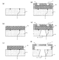
図2に示すインクジェット記録ヘッドでは、エネルギー発生素子2を複数有する基板1上に、インクを保持するインク流路3cと、インク流路3cと連通しインクを吐出するためのインク吐出口5とを形成するインク流路形成層4が設けられている。また、基板1には、インクをインク流路3cに供給するインク供給口6が設けられている。以下、図2及び図3のA−B断面図である図4を参照しつつ、本発明に係る液体吐出装置及びその製造方法について説明する。なお、図3及び図4(a)に示すように、基板1上には、エネルギー発生素子2が所定のピッチで複数個配置されており、そのエネルギー発生素子2には、素子を動作させるための制御信号入力電極(図示せず)が接続されている。
In the ink jet recording head shown in FIG. 2, an
基板1は、シリコン基板であることが好ましい。特に、シリコン単結晶体基板であることが好ましく、基板1の貫通孔の穿設を異方性エッチングにより行う場合は、結晶方位100のシリコン単結晶体基板であることが好ましい。基板1の貫通孔の穿設をドライエッチング、サンドブラスト又はレーザーにより行う場合は、結晶方位110のシリコン単結晶体基板等でもよい。
The
エネルギー発生素子2は、インク液小滴を吐出させるための吐出エネルギーがインクに与えられ、インク液滴がインク吐出口から吐出可能なものであれば、特に限定はされない。例えば、エネルギー発生素子2として発熱抵抗素子が用いられる場合、その発熱抵抗素子が近傍のインクを加熱することにより、インクに状態変化を生起させ吐出エネルギーが発生する。
The
前記基板1上に、溶解可能な樹脂組成物を塗布し、インク流路パターン層3aを形成する(図4(b))。インク流路パターン層3aの形成方法としては、ポジ型感光性樹脂を適宜溶媒に溶解し、スピンコート法等により前記基板1上に塗布した後、加熱することでインク流路パターン層3aを形成することができる。インク流路パターン層3aの厚さとしては、所望のインク流路の高さとすればよく、特に限定されるものではないが、2〜50μmであることが好ましい。
A dissolvable resin composition is applied on the
次に、インク流路パターン層3aに放射線を照射し、現像することにより、インク流路パターン3bを形成する(図4(c))。
Next, the ink flow
次に、インク流路パターン3b及び基板1上に、本発明に係る感光性樹脂組成物からなるインク流路形成層4を形成する。インク流路形成層4の厚さは、インク流路パターン3b上の厚さとして2μm以上であることが好ましい。また、インク流路形成層4の厚さの上限は、インク吐出口部の現像性が損なわれない範囲であれば、特に制限されるものではないが、インク流路パターン3b上の厚みとして100μm以下が好ましい。
Next, the ink flow
次に、インク流路形成層4に放射線を照射し、その後MIBK(メチルイソブチルケトン)等により現像を行い、更にIPA等によりリンス処理を行うことで、インク吐出口5を形成する(図4(d))。その後、エッチング処理などの適当な方法によりインク供給口6を形成する(図4(e))。
Next, the ink flow
次に、インク流路パターン3bを適当な溶媒に溶解して除去する(図4(f))。用いる溶媒は、アルカリ水溶液でも有機溶媒でもよい。
Next, the ink
その後、基板1をダイシングソー等により切断分離、チップ化し、エネルギー発生素子2を駆動させるための電気的接合を行う。更に、インク供給のためのチップタンク部材を接続して、インクジェット記録ヘッドが完成する。
Thereafter, the
なお、上記の方法は、インクジェット記録ヘッドの製造方法に限られず、中空パターンを形成するパターン形成方法としても有効である。 The above method is not limited to the method of manufacturing the ink jet recording head, and is also effective as a pattern forming method for forming a hollow pattern.
以下、本発明の実施例について説明するが、本発明はこれら実施例に限定されるものではない。 Examples of the present invention will be described below, but the present invention is not limited to these examples.
<実施例1〜9、比較例1〜4>
表1に記載の配合(単位は質量部)に従って、(a)成分としての多官能エポキシ樹脂と、(b)成分としての光酸発生剤と、溶剤と、必要に応じて(c)成分や、(d)成分を配合した感光性樹脂組成物を得た。なお、実施例8及び9は参考例である。また、溶剤としては、プロピレングリコールモノメチルエーテルアセテート/プロピレンカーボネート=25/1の質量比率の混合溶剤を用い、その配合量は、(a)成分100質量部に対して80質量部とした。
<Examples 1-9, Comparative Examples 1-4>
According to the composition shown in Table 1 (unit is part by mass), the polyfunctional epoxy resin as the component (a), the photoacid generator as the component (b), the solvent, and the component (c) (D) The photosensitive resin composition which mix | blended component was obtained. Examples 8 and 9 are reference examples. Moreover, as a solvent, the mixed solvent of the mass ratio of propylene glycol monomethyl ether acetate / propylene carbonate = 25/1 was used, and the compounding quantity was 80 mass parts with respect to 100 mass parts of (a) component.
これら感光性樹脂組成物を、シリコンウエハーからなる支持体上にスピンコーターで塗布した後、90℃で5分のプリベーク乾燥して、20μmの膜厚を有する感光性樹脂組成物層を得た。プリベーク後、FPA−3000i5+(キヤノン社製商品名、i線ステッパー)を用いて所望のパターンが描写されたマスクを介してパターン露光を行い、ホットプレートにより90℃で4分の露光後ベークを行った。その後、CDS−630+(キヤノン社製商品名)を用いて現像処理を行った。次いで、現像後の樹脂パターンを基板ごと、オーブンを用いて140℃で1時間のポストベークを行い、支持体上に硬化したレジストパターンを得た。 These photosensitive resin compositions were coated on a support made of a silicon wafer by a spin coater and then pre-baked at 90 ° C. for 5 minutes to obtain a photosensitive resin composition layer having a thickness of 20 μm. After pre-baking, pattern exposure is performed through a mask on which a desired pattern is drawn using FPA-3000i5 + (trade name, manufactured by Canon Inc., i-line stepper), and post-exposure baking is performed at 90 ° C. for 4 minutes using a hot plate. It was. Thereafter, development processing was performed using CDS-630 + (trade name, manufactured by Canon Inc.). Subsequently, the developed resin pattern was post-baked for 1 hour at 140 ° C. using an oven together with the substrate, to obtain a resist pattern cured on the support.
ここで、比較例1〜3では、(b)成分に対応する光酸発生剤として、R1〜R3の全構成原子中に酸素原子を1つのみ含有し、かつ、(b1)構造中にチオキサントン骨格、9,10−ジアルコキシアントラセン骨格、およびアントラキノン骨格をいずれも含有しない(b1−27)を含有するスルホニウム塩を用いた。また、比較例4では、(b)成分に対応する光酸発生剤として、R1〜R3の全構成原子中に酸素原子を含有せず、かつ、(b1)構造中にチオキサントン骨格、9,10−ジアルコキシアントラセン骨格、およびアントラキノン骨格をいずれも含有しない(b1−28)を含有するスルホニウム塩を用いた。 Here, in Comparative Examples 1 to 3, the photoacid generator corresponding to the component (b) contains only one oxygen atom in all the constituent atoms of R 1 to R 3 , and (b1) in the structure A sulfonium salt containing (b1-27) containing no thioxanthone skeleton, 9,10-dialkoxyanthracene skeleton, and anthraquinone skeleton was used. In Comparative Example 4, as a photoacid generator corresponding to component (b), oxygen atoms are not contained in all constituent atoms of R 1 to R 3 , and (b1) a thioxanthone skeleton, 9 , 10-dialkoxyanthracene skeleton and sulfonium salt containing (b1-28) containing neither anthraquinone skeleton was used.
<評価>
(感度)
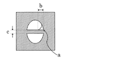
図1に示したマスクを用い、設計寸法が長軸20μm×短軸16μmの楕円ノズル口における短軸に沿って幅3μm(図1のc)のラインパターンで橋渡ししたモデルパターンを転写し、ネガ型レジストパターンを形成した。このパターン形成にあたっては、露光量を500〜20000J/m2の範囲で段階的に変更してi線露光を行い、得られたパターンが上記設計サイズに形成されるために必要な露光量を測定した。
<Evaluation>
(sensitivity)
Using the mask shown in FIG. 1, a model pattern bridged by a line pattern having a width of 3 μm (c in FIG. 1) is transferred along the short axis of an elliptical nozzle opening having a major axis of 20 μm × short axis of 16 μm. A mold resist pattern was formed. In this pattern formation, the exposure amount is changed stepwise in the range of 500 to 20000 J / m 2 and i-line exposure is performed, and the exposure amount necessary for the obtained pattern to be formed to the above design size is measured. did.
(造形精度)
楕円と橋渡しラインパターンが交差する部分を走査型電子顕微鏡(SEM)にて観察し、その解像性を測定した。マスクパターンに忠実にレジストパターンが形成できた場合の半月型の端部(図1のa)から、橋渡しラインパターンのエッジ上に沿った仮想直線を引いた時、この仮想直線と実際に解像したパターンが交差する距離(図1のb)を造形精度とした(単位はμm)。これは、実際のパターンが、半月型の端部(図1のa)まで解像している場合、造形精度が0μmとなることを意味し、設計寸法に一致していることを示す。しかし、造形精度が低下すると、半月型の端部(図1のa)にネガ化物が残るので、このネガ化物の広がりの程度により造形精度の値を決定される。
(Modeling accuracy)
The portion where the ellipse and the bridging line pattern intersect was observed with a scanning electron microscope (SEM), and the resolution was measured. When a virtual line along the edge of the bridging line pattern is drawn from the half-moon shaped end (a in FIG. 1) when the resist pattern can be formed faithfully to the mask pattern, the virtual line is actually resolved. The distance (b in FIG. 1) at which the patterns intersected was defined as modeling accuracy (unit: μm). This means that when the actual pattern is resolved to the half-moon-shaped end (a in FIG. 1), the modeling accuracy is 0 μm, which indicates that it matches the design dimension. However, if the modeling accuracy is lowered, a negative product remains at the end portion of the half moon (a in FIG. 1), and the value of the modeling accuracy is determined by the extent of the spread of the negative product.
(吸光率)
吸光度の評価では、まず、以下の2つの組成物を準備した。
<組成物1>
上記で得られた感光性樹脂組成物。
<組成物2>
(b)成分を配合しないこと以外は、上記と同様の方法で得られた感光性樹脂組成物。
(Absorbance)
For the evaluation of absorbance, first, the following two compositions were prepared.
<
The photosensitive resin composition obtained above.
<
(B) The photosensitive resin composition obtained by the method similar to the above except not mix | blending a component.
次に、石英ガラスからなる支持体上に、上記組成物1及び組成物2をそれぞれスピンコーターで塗布した後、90℃5分プリベーク乾燥して、約20μmの膜厚を有する樹脂組成物層1及び樹脂組成物層2をそれぞれ得た。次に、U−3300形分光光度計(日立製作所製商品名)を使用して、樹脂組成物層1及び樹脂組成物層2の波長365nmでの吸光度(単位はAbs)をそれぞれ測定した。また、樹脂組成物層1及び樹脂組成物層2の膜厚(単位はμm)をそれぞれ測定した。そして、得られた測定結果から、以下の計算式により、感光性樹脂組成物が吸収する波長365nmの光のうち、(b)成分が吸収する波長365nmの光の割合を算出した。この値を吸光率と称する(単位は%)。
Next, the
<計算式>
吸光率=[(樹脂組成物層1の吸光度/樹脂組成物層1の膜厚)−(樹脂組成物層2の吸光度/樹脂組成物層2の膜厚)]÷(樹脂組成物1の吸光度/樹脂組成物1の膜厚)×100
<Calculation formula>
Absorbance = [(absorbance of
(a−1):エピクロンN−865(大日本インキ化学工業製商品名)、エポキシ当量:210、軟化点:68℃
(a−2):JER157S70(ジャパンエポキシレジン製商品名)、エポキシ当量:210、軟化点:70℃
(a−3):EHPE3150(ダイセル化学工業製商品名)、エポキシ当量:180、軟化点:85℃
(A-1): Epicron N-865 (trade name, manufactured by Dainippon Ink and Chemicals), epoxy equivalent: 210, softening point: 68 ° C
(A-2): JER157S70 (trade name, manufactured by Japan Epoxy Resin), epoxy equivalent: 210, softening point: 70 ° C
(A-3): EHPE3150 (trade name, manufactured by Daicel Chemical Industries), epoxy equivalent: 180, softening point: 85 ° C
(b1−28):トリフェニルスルホニウム
(c−1):4−アミノエチルピリジン
(d−8):1−ナフトール(増感剤)
実施例1〜9では、4000J/m2以下の小さい露光量で液滴吐出口モデルパターンを形成することができた。この時の造形精度は2.0μm以下と微細なものであった。
(B1-28): Triphenylsulfonium (c-1): 4-aminoethylpyridine (d-8): 1-naphthol (sensitizer)
In Examples 1 to 9, a droplet discharge port model pattern could be formed with a small exposure amount of 4000 J / m 2 or less. The modeling accuracy at this time was as fine as 2.0 μm or less.
一方、比較例1〜4では、高感度、すなわち小さい露光量と微細な造形精度の両立はできなかった。なお、これらの比較例では、(b1)で表されるカチオン部構造が、チオキサントン骨格、9,10−ジアルコキシアントラセン骨格、およびアントラキノン骨格をいずれも有さず、かつ酸素原子を2つ以上含有していない。また、比較例3及び4のように、(b)成分による露光光の吸光割合、すなわち吸光率が50%より小さい場合、造形精度の低下が観察された。 On the other hand, in Comparative Examples 1 to 4, high sensitivity, that is, it was impossible to achieve both small exposure and fine modeling accuracy. In these comparative examples, the cation moiety structure represented by (b1) has no thioxanthone skeleton, 9,10-dialkoxyanthracene skeleton, and anthraquinone skeleton, and contains two or more oxygen atoms. Not done. Further, as in Comparative Examples 3 and 4, when the light absorption ratio of the exposure light by the component (b), that is, the light absorption ratio is smaller than 50%, a decrease in modeling accuracy was observed.
以上より、本発明に係る感光性樹脂組成物によれば、感度及び造形精度が高いパターニングが可能となるので、MEMS用等の微細加工を施した各種デバイスの製造に好適に用いられる。 As mentioned above, according to the photosensitive resin composition concerning this invention, since a pattern with high sensitivity and modeling precision is attained, it is used suitably for manufacture of the various devices which gave microfabrication for MEMS etc.
1 基板
2 エネルギー発生素子
3a インク流路パターン層
3b インク流路パターン
3c インク流路
4 インク流路形成層
5 インク吐出口
6 インク供給口
DESCRIPTION OF
Claims (16)
前記感光性樹脂組成物は、酸により重合可能な化合物と、光酸発生剤と、を含有し、前記光酸発生剤が、カチオン部構造及びアニオン部構造を含有するオニウム塩を含み、かつ前記光酸発生剤が、前記感光性樹脂組成物が吸収する波長365nmの光のうち80%以上を吸収し、
前記カチオン部構造は下記(b1)で表され、
前記アニオン部構造として、以下の式(b2−1)、(b2−2)、(b2−11)、(b2−12)及び(b2−22)の少なくとも1つを含む、
The photosensitive resin composition contains a compound polymerizable with an acid and a photoacid generator, and the photoacid generator contains an onium salt containing a cation moiety structure and an anion moiety structure, and The photoacid generator absorbs 80% or more of light having a wavelength of 365 nm absorbed by the photosensitive resin composition,
The cation moiety structure is represented by the following (b1),
The anion moiety structure includes at least one of the following formulas (b2-1), (b2-2), (b2-11), (b2-12), and (b2-22).
Priority Applications (1)
| Application Number | Priority Date | Filing Date | Title |
|---|---|---|---|
| JP2011021767A JP5822477B2 (en) | 2010-02-05 | 2011-02-03 | Liquid ejecting apparatus and manufacturing method thereof |
Applications Claiming Priority (3)
| Application Number | Priority Date | Filing Date | Title |
|---|---|---|---|
| JP2010024681 | 2010-02-05 | ||
| JP2010024681 | 2010-02-05 | ||
| JP2011021767A JP5822477B2 (en) | 2010-02-05 | 2011-02-03 | Liquid ejecting apparatus and manufacturing method thereof |
Publications (3)
| Publication Number | Publication Date |
|---|---|
| JP2011180586A JP2011180586A (en) | 2011-09-15 |
| JP2011180586A5 JP2011180586A5 (en) | 2014-03-20 |
| JP5822477B2 true JP5822477B2 (en) | 2015-11-24 |
Family
ID=44355213
Family Applications (1)
| Application Number | Title | Priority Date | Filing Date |
|---|---|---|---|
| JP2011021767A Active JP5822477B2 (en) | 2010-02-05 | 2011-02-03 | Liquid ejecting apparatus and manufacturing method thereof |
Country Status (6)
| Country | Link |
|---|---|
| US (1) | US8980968B2 (en) |
| EP (2) | EP3064996B1 (en) |
| JP (1) | JP5822477B2 (en) |
| CN (1) | CN102754028B (en) |
| RU (1) | RU2526258C2 (en) |
| WO (1) | WO2011096195A1 (en) |
Families Citing this family (9)
| Publication number | Priority date | Publication date | Assignee | Title |
|---|---|---|---|---|
| JP5787720B2 (en) * | 2010-12-16 | 2015-09-30 | キヤノン株式会社 | Photosensitive negative resin composition |
| JP6120574B2 (en) * | 2012-01-31 | 2017-04-26 | キヤノン株式会社 | Photosensitive negative resin composition, fine structure, method for producing fine structure, and liquid discharge head |
| JP5739497B2 (en) * | 2012-09-15 | 2015-06-24 | ローム アンド ハース エレクトロニック マテリアルズ エルエルシーRohm and Haas Electronic Materials LLC | Acid generator compound and photoresist containing the same |
| JP6071718B2 (en) | 2013-04-10 | 2017-02-01 | キヤノン株式会社 | Photosensitive negative resin composition |
| WO2015174471A1 (en) * | 2014-05-13 | 2015-11-19 | 東洋合成工業株式会社 | Onium salt, photoacid generator, photosensitive resin composition, and method for producing device |
| JP6797911B2 (en) * | 2016-06-09 | 2020-12-09 | サンアプロ株式会社 | Sulfonium salt, photoacid generator, curable composition and resist composition |
| US9938136B2 (en) * | 2016-08-18 | 2018-04-10 | Stmicroelectronics Asia Pacific Pte Ltd | Fluid ejection device |
| US20190056659A1 (en) * | 2017-08-21 | 2019-02-21 | Funai Electric Co., Ltd. | Method for manufacturing mems devices using multiple photoacid generators in a composite photoimageable dry film |
| JP7413039B2 (en) | 2020-01-22 | 2024-01-15 | キヤノン株式会社 | Liquid ejection head and method for manufacturing liquid ejection head |
Family Cites Families (34)
| Publication number | Priority date | Publication date | Assignee | Title |
|---|---|---|---|---|
| IE42085B1 (en) * | 1974-09-18 | 1980-06-04 | Ici Ltd | Photopolymerisable compositions |
| GB1526923A (en) | 1974-09-18 | 1978-10-04 | Ici Ltd | Photopolymerisable compositions |
| JPH0412859A (en) | 1990-04-28 | 1992-01-17 | Canon Inc | Liquid jetting method, recording head using the method and recording apparatus using the method |
| ES2073614T3 (en) | 1990-04-27 | 1995-08-16 | Canon Kk | PRINTING METHOD AND APPARATUS. |
| US5639802A (en) * | 1991-05-20 | 1997-06-17 | Spectra Group Limited, Inc. | Cationic polymerization |
| JPH07145346A (en) | 1993-11-22 | 1995-06-06 | Dainippon Ink & Chem Inc | Resin composition for solder resist ink |
| JPH08157510A (en) * | 1994-12-09 | 1996-06-18 | Nippon Kayaku Co Ltd | Photopolymerization initiator, actinic-radiation-curing composition containing the same, and cured product thereof |
| JPH0925393A (en) | 1995-05-09 | 1997-01-28 | Toray Ind Inc | Epoxy resin composition for fiber reinforced composite material, prepreg and fiber reinforced composite material |
| JPH0912615A (en) * | 1995-06-29 | 1997-01-14 | Nippon Kayaku Co Ltd | Actinic-radiation-curing composition and cured product thereof |
| JPH107680A (en) | 1996-06-18 | 1998-01-13 | Nippon Kayaku Co Ltd | Photopolymerization initiator, energy ray-curable composition containing the same and its cured product |
| CN1195356A (en) * | 1996-06-12 | 1998-10-07 | 日本化药株式会社 | Photopolymerization initiator and actinic radiation-curable composition comprising same |
| JPH10152554A (en) | 1996-11-21 | 1998-06-09 | Nippon Kayaku Co Ltd | Composition curable by energy ray and its cured product |
| JPH10212286A (en) | 1997-01-30 | 1998-08-11 | Nippon Kayaku Co Ltd | Photoinitiator, energy ray-hardenable composition containing the same and hardened material thereof |
| JPH11322900A (en) | 1998-03-19 | 1999-11-26 | Nippon Soda Co Ltd | Photocurable composition and curing |
| JP4385437B2 (en) * | 1999-05-10 | 2009-12-16 | Jsr株式会社 | Radiation sensitive composition for color filter and color filter using the same |
| EP1295180B1 (en) | 2000-06-15 | 2013-05-22 | 3M Innovative Properties Company | Process for producing microfluidic articles |
| JP3978601B2 (en) * | 2001-09-27 | 2007-09-19 | 信越化学工業株式会社 | Chemically amplified resist material and pattern forming method |
| JP3880912B2 (en) | 2002-10-10 | 2007-02-14 | ジャパンエポキシレジン株式会社 | Epoxy resin composition for semiconductor encapsulation |
| KR101197539B1 (en) * | 2003-11-04 | 2012-11-12 | 헨켈 아게 운트 코. 카게아아 | Sulfonium salt photoinitiators and use thereof |
| JP4593309B2 (en) | 2005-01-21 | 2010-12-08 | 東京応化工業株式会社 | Method for forming a top plate in a precise fine space |
| JP2006241384A (en) | 2005-03-07 | 2006-09-14 | Fuji Photo Film Co Ltd | Ink composition, inkjet recording method, printed article, planographic printing plate and method for producing the same |
| JP2007034153A (en) | 2005-07-29 | 2007-02-08 | Toyo Ink Mfg Co Ltd | Energy line-sensitive polymerizable composition, negative resist using the same and pictorial pattern forming method using the same |
| US20080292993A1 (en) * | 2006-12-22 | 2008-11-27 | Canon Kabushiki Kaisha | Photo-cationic polymerizable epoxy resin composition, liquid discharge head, and manufacturing method thereof |
| JP4355725B2 (en) | 2006-12-25 | 2009-11-04 | 信越化学工業株式会社 | Positive resist material and pattern forming method |
| JP4564977B2 (en) | 2007-04-05 | 2010-10-20 | 東京応化工業株式会社 | Photosensitive resin composition, method for producing resist pattern, laminate, and device |
| JP2008292993A (en) | 2007-04-24 | 2008-12-04 | Ricoh Co Ltd | Image forming apparatus |
| JP5039442B2 (en) | 2007-06-15 | 2012-10-03 | 東京応化工業株式会社 | Photosensitive resin composition, photosensitive resin laminate, and pattern forming method |
| JP4998112B2 (en) * | 2007-06-27 | 2012-08-15 | 住友化学株式会社 | Chemically amplified positive resist composition |
| JP2010276623A (en) | 2008-03-26 | 2010-12-09 | Panasonic Electric Works Co Ltd | Process for forming transparent resin structure on three-dimensional substrate |
| JP2009244779A (en) | 2008-03-31 | 2009-10-22 | Fujifilm Corp | Negative type resist composition and pattern forming method |
| JP2009258506A (en) | 2008-04-18 | 2009-11-05 | Fujifilm Corp | Negative resist composition and resist pattern-forming method |
| JP5208573B2 (en) * | 2008-05-06 | 2013-06-12 | サンアプロ株式会社 | Sulfonium salt, photoacid generator, photocurable composition and cured product thereof |
| JP5247396B2 (en) | 2008-07-02 | 2013-07-24 | 日本化薬株式会社 | Photosensitive resin composition for MEMS and cured product thereof |
| EP2441778A1 (en) | 2009-06-08 | 2012-04-18 | Sanyo Chemical Industries, Ltd. | Photosensitive composition |
-
2011
- 2011-02-01 EP EP16000494.1A patent/EP3064996B1/en active Active
- 2011-02-01 RU RU2012137721/04A patent/RU2526258C2/en not_active IP Right Cessation
- 2011-02-01 CN CN201180008124.9A patent/CN102754028B/en active Active
- 2011-02-01 WO PCT/JP2011/000549 patent/WO2011096195A1/en active Application Filing
- 2011-02-01 US US13/576,895 patent/US8980968B2/en active Active
- 2011-02-01 EP EP11739545.9A patent/EP2531890B1/en active Active
- 2011-02-03 JP JP2011021767A patent/JP5822477B2/en active Active
Also Published As
| Publication number | Publication date |
|---|---|
| WO2011096195A1 (en) | 2011-08-11 |
| EP2531890A1 (en) | 2012-12-12 |
| EP3064996A1 (en) | 2016-09-07 |
| RU2526258C2 (en) | 2014-08-20 |
| US8980968B2 (en) | 2015-03-17 |
| EP2531890B1 (en) | 2019-08-28 |
| JP2011180586A (en) | 2011-09-15 |
| RU2012137721A (en) | 2014-03-10 |
| CN102754028B (en) | 2015-06-03 |
| CN102754028A (en) | 2012-10-24 |
| EP2531890A4 (en) | 2013-11-06 |
| US20120292412A1 (en) | 2012-11-22 |
| EP3064996B1 (en) | 2020-07-22 |
Similar Documents
| Publication | Publication Date | Title |
|---|---|---|
| JP5822477B2 (en) | Liquid ejecting apparatus and manufacturing method thereof | |
| JP5247138B2 (en) | Method for manufacturing liquid discharge head | |
| JP5159823B2 (en) | Structure manufacturing method and liquid discharge head manufacturing method | |
| JP5709561B2 (en) | Liquid discharge head | |
| JP5787720B2 (en) | Photosensitive negative resin composition | |
| JP5473645B2 (en) | Photosensitive resin composition and liquid discharge head | |
| JP4533256B2 (en) | Method for manufacturing fine structure and method for manufacturing liquid discharge head | |
| JP2012101410A (en) | Process for forming hydrophilic coating and hydrophilic coating, and method for manufacturing inkjet recording head and inkjet recording head | |
| US9707757B2 (en) | Photosensitive negative resin composition | |
| JP3986060B2 (en) | Inkjet recording head flow path component and inkjet recording head manufacturing method | |
| JP2018183980A (en) | Method for manufacturing liquid discharge head | |
| JP4702784B2 (en) | Liquid discharge type recording head flow path constituent material | |
| JP2023018861A (en) | Photosensitive resin composition, molding, method for producing molding, and method for manufacturing liquid discharge head | |
| JP2007196436A (en) | Inkjet recording head |
Legal Events
| Date | Code | Title | Description |
|---|---|---|---|
| A521 | Written amendment |
Free format text: JAPANESE INTERMEDIATE CODE: A523 Effective date: 20140203 |
|
| A621 | Written request for application examination |
Free format text: JAPANESE INTERMEDIATE CODE: A621 Effective date: 20140203 |
|
| RD04 | Notification of resignation of power of attorney |
Free format text: JAPANESE INTERMEDIATE CODE: A7424 Effective date: 20140430 |
|
| A131 | Notification of reasons for refusal |
Free format text: JAPANESE INTERMEDIATE CODE: A131 Effective date: 20140902 |
|
| A521 | Written amendment |
Free format text: JAPANESE INTERMEDIATE CODE: A523 Effective date: 20141104 |
|
| A131 | Notification of reasons for refusal |
Free format text: JAPANESE INTERMEDIATE CODE: A131 Effective date: 20141125 |
|
| A521 | Written amendment |
Free format text: JAPANESE INTERMEDIATE CODE: A523 Effective date: 20150126 |
|
| A02 | Decision of refusal |
Free format text: JAPANESE INTERMEDIATE CODE: A02 Effective date: 20150331 |
|
| A521 | Written amendment |
Free format text: JAPANESE INTERMEDIATE CODE: A523 Effective date: 20150630 |
|
| A911 | Transfer to examiner for re-examination before appeal (zenchi) |
Free format text: JAPANESE INTERMEDIATE CODE: A911 Effective date: 20150708 |
|
| A131 | Notification of reasons for refusal |
Free format text: JAPANESE INTERMEDIATE CODE: A131 Effective date: 20150804 |
|
| A521 | Written amendment |
Free format text: JAPANESE INTERMEDIATE CODE: A523 Effective date: 20150807 |
|
| TRDD | Decision of grant or rejection written | ||
| A01 | Written decision to grant a patent or to grant a registration (utility model) |
Free format text: JAPANESE INTERMEDIATE CODE: A01 Effective date: 20150908 |
|
| A61 | First payment of annual fees (during grant procedure) |
Free format text: JAPANESE INTERMEDIATE CODE: A61 Effective date: 20151006 |
|
| R151 | Written notification of patent or utility model registration |
Ref document number: 5822477 Country of ref document: JP Free format text: JAPANESE INTERMEDIATE CODE: R151 |