JP5821812B2 - Wireless communication device - Google Patents
Wireless communication device Download PDFInfo
- Publication number
- JP5821812B2 JP5821812B2 JP2012193248A JP2012193248A JP5821812B2 JP 5821812 B2 JP5821812 B2 JP 5821812B2 JP 2012193248 A JP2012193248 A JP 2012193248A JP 2012193248 A JP2012193248 A JP 2012193248A JP 5821812 B2 JP5821812 B2 JP 5821812B2
- Authority
- JP
- Japan
- Prior art keywords
- phase shift
- vehicle
- shift amount
- antennas
- communication
- Prior art date
- Legal status (The legal status is an assumption and is not a legal conclusion. Google has not performed a legal analysis and makes no representation as to the accuracy of the status listed.)
- Active
Links
Images


Classifications
-
- H—ELECTRICITY
- H04—ELECTRIC COMMUNICATION TECHNIQUE
- H04L—TRANSMISSION OF DIGITAL INFORMATION, e.g. TELEGRAPHIC COMMUNICATION
- H04L27/00—Modulated-carrier systems
- H04L27/18—Phase-modulated carrier systems, i.e. using phase-shift keying
-
- H—ELECTRICITY
- H01—ELECTRIC ELEMENTS
- H01Q—ANTENNAS, i.e. RADIO AERIALS
- H01Q3/00—Arrangements for changing or varying the orientation or the shape of the directional pattern of the waves radiated from an antenna or antenna system
- H01Q3/26—Arrangements for changing or varying the orientation or the shape of the directional pattern of the waves radiated from an antenna or antenna system varying the relative phase or relative amplitude of energisation between two or more active radiating elements; varying the distribution of energy across a radiating aperture
-
- H—ELECTRICITY
- H01—ELECTRIC ELEMENTS
- H01Q—ANTENNAS, i.e. RADIO AERIALS
- H01Q1/00—Details of, or arrangements associated with, antennas
- H01Q1/27—Adaptation for use in or on movable bodies
- H01Q1/32—Adaptation for use in or on road or rail vehicles
- H01Q1/325—Adaptation for use in or on road or rail vehicles characterised by the location of the antenna on the vehicle
- H01Q1/3275—Adaptation for use in or on road or rail vehicles characterised by the location of the antenna on the vehicle mounted on a horizontal surface of the vehicle, e.g. on roof, hood, trunk
-
- H—ELECTRICITY
- H01—ELECTRIC ELEMENTS
- H01Q—ANTENNAS, i.e. RADIO AERIALS
- H01Q21/00—Antenna arrays or systems
- H01Q21/28—Combinations of substantially independent non-interacting antenna units or systems
-
- H—ELECTRICITY
- H03—ELECTRONIC CIRCUITRY
- H03F—AMPLIFIERS
- H03F3/00—Amplifiers with only discharge tubes or only semiconductor devices as amplifying elements
- H03F3/20—Power amplifiers, e.g. Class B amplifiers, Class C amplifiers
- H03F3/24—Power amplifiers, e.g. Class B amplifiers, Class C amplifiers of transmitter output stages
-
- H—ELECTRICITY
- H04—ELECTRIC COMMUNICATION TECHNIQUE
- H04B—TRANSMISSION
- H04B1/00—Details of transmission systems, not covered by a single one of groups H04B3/00 - H04B13/00; Details of transmission systems not characterised by the medium used for transmission
- H04B1/38—Transceivers, i.e. devices in which transmitter and receiver form a structural unit and in which at least one part is used for functions of transmitting and receiving
- H04B1/40—Circuits
-
- H—ELECTRICITY
- H04—ELECTRIC COMMUNICATION TECHNIQUE
- H04B—TRANSMISSION
- H04B7/00—Radio transmission systems, i.e. using radiation field
- H04B7/02—Diversity systems; Multi-antenna system, i.e. transmission or reception using multiple antennas
- H04B7/04—Diversity systems; Multi-antenna system, i.e. transmission or reception using multiple antennas using two or more spaced independent antennas
- H04B7/06—Diversity systems; Multi-antenna system, i.e. transmission or reception using multiple antennas using two or more spaced independent antennas at the transmitting station
- H04B7/0613—Diversity systems; Multi-antenna system, i.e. transmission or reception using multiple antennas using two or more spaced independent antennas at the transmitting station using simultaneous transmission
- H04B7/0615—Diversity systems; Multi-antenna system, i.e. transmission or reception using multiple antennas using two or more spaced independent antennas at the transmitting station using simultaneous transmission of weighted versions of same signal
- H04B7/0617—Diversity systems; Multi-antenna system, i.e. transmission or reception using multiple antennas using two or more spaced independent antennas at the transmitting station using simultaneous transmission of weighted versions of same signal for beam forming
-
- H—ELECTRICITY
- H04—ELECTRIC COMMUNICATION TECHNIQUE
- H04B—TRANSMISSION
- H04B7/00—Radio transmission systems, i.e. using radiation field
- H04B7/02—Diversity systems; Multi-antenna system, i.e. transmission or reception using multiple antennas
- H04B7/04—Diversity systems; Multi-antenna system, i.e. transmission or reception using multiple antennas using two or more spaced independent antennas
- H04B7/08—Diversity systems; Multi-antenna system, i.e. transmission or reception using multiple antennas using two or more spaced independent antennas at the receiving station
-
- H—ELECTRICITY
- H04—ELECTRIC COMMUNICATION TECHNIQUE
- H04B—TRANSMISSION
- H04B7/00—Radio transmission systems, i.e. using radiation field
- H04B7/02—Diversity systems; Multi-antenna system, i.e. transmission or reception using multiple antennas
- H04B7/10—Polarisation diversity; Directional diversity
-
- H—ELECTRICITY
- H04—ELECTRIC COMMUNICATION TECHNIQUE
- H04B—TRANSMISSION
- H04B1/00—Details of transmission systems, not covered by a single one of groups H04B3/00 - H04B13/00; Details of transmission systems not characterised by the medium used for transmission
- H04B1/02—Transmitters
- H04B1/04—Circuits
- H04B2001/0408—Circuits with power amplifiers
Landscapes
- Engineering & Computer Science (AREA)
- Computer Networks & Wireless Communication (AREA)
- Signal Processing (AREA)
- Remote Sensing (AREA)
- Power Engineering (AREA)
- Variable-Direction Aerials And Aerial Arrays (AREA)
- Radio Transmission System (AREA)
Description
本発明は、無線により送信および受信を行なう無線通信装置に関し、特に、受信ダイバーシティを行なうことができる無線通信装置に関する。 The present invention relates to a wireless communication apparatus that performs transmission and reception wirelessly, and more particularly to a wireless communication apparatus that can perform reception diversity.
受信ダイバーシティを行なうことができる無線通信装置が広く知られている(たとえば特許文献1)。特許文献1では、2つのアンテナ素子を備えており、切り替えスイッチにより2つのアンテナ素子のうちのいずれを用いて受信を行なうかを切り替えることで、アンテナ全体としての指向性を変化させている。
A wireless communication apparatus capable of performing reception diversity is widely known (for example, Patent Document 1). In
しかし、受信ダイバーシティを行なうために2つのアンテナを備えていても、送信に用いるのは、いずれか一つのアンテナのみであり送信性能は十分ではなかった。 However, even if two antennas are provided to perform reception diversity, only one of the antennas is used for transmission, and the transmission performance is not sufficient.
本発明は、この事情に基づいて成されたものであり、その目的とするところは、受信ダイバーシティを行なうことができる無線通信装置において送信性能を向上させることにある。 The present invention has been made based on this situation, and an object of the present invention is to improve transmission performance in a wireless communication apparatus capable of performing reception diversity.
その目的を達成するための第1発明は、複数のアンテナ(110A、110B)と、複数のアンテナを用いてダイバーシティ受信する受信部(221、222)と、送信部(223)と、複数のアンテナに接続される切り替え回路(120A、120B)と、切り替え回路と、複数のアンテナと送信部とを接続する伝送線路に配置され、送信時には送信部から出力された信号を複数のアンテナに分配する分配器(130)と、その分配器と複数のアンテナとをそれぞれ接続する複数の伝送線路のうちのいずれか少なくとも一つの伝送線路に設けられた移相器(140)と、移相器の移相量を制御する制御部(200)とを備え、車両に搭載されている無線通信装置であって、車車間通信時であるか路車間通信時であるかを判断する通信種別判断手段(210、S31)と、車車間通信時における移相器の移相量、および、路車間通信時における移相器の移相量を記憶した記憶部(212)とを備え、制御部は、通信種別判断手段により車車間通信時と判断した場合には記憶部から車車間通信時の移相量を読み出して移相器の移相量を設定し、通信種別判断手段が路車間通信時と判断した場合には記憶部から路車間通信時の移相量を読み出して移相器の移相量を設定することを特徴とする無線通信装置である。
また、上記目的を達成するための第2発明は、複数のアンテナ(110A、110B)と、複数のアンテナを用いてダイバーシティ受信する受信部(221、222)と、送信部(223)と、複数のアンテナに接続される切り替え回路(120A、120B)と、切り替え回路と送信部とを接続する伝送線路に配置され、送信時には送信部から出力された信号を複数のアンテナに分配する分配器(130)と、その分配器と複数のアンテナとをそれぞれ接続する複数の伝送線路のうちのいずれか少なくとも一つの伝送線路に設けられた移相器(140)と、移相器の移相量を制御する制御部(200)とを備え、車両に搭載されている無線通信装置であって、複数のアンテナは、車両の上下方向における位置が異なるように配置されており、仰角が互いに異なる指向性とすることができる移相量を複数記憶するとともに、それぞれの移相量に対応する車両モデルを記憶した記憶部(212)と、車両の車両モデルを取得する取得手段(210、S101)とを備え、制御部は、取得手段が取得した車両モデルに対応する移相量を、記憶部から読みだして移相器の移相量を設定することを特徴とする無線通信装置である。
A first invention for achieving the object includes a plurality of antennas (110A, 110B), a reception unit (221, 222) that receives diversity using the plurality of antennas, a transmission unit (223), and a plurality of antennas. The switching circuit (120A, 120B) connected to the transmission circuit, the switching circuit, a distribution line that connects the plurality of antennas and the transmission unit, and distributes the signal output from the transmission unit to the plurality of antennas during transmission , A phase shifter (140) provided on at least one of the plurality of transmission lines that respectively connect the distributor and the plurality of antennas, and a phase shift of the phase shifter A control unit (200) for controlling the amount, and a wireless communication device mounted on the vehicle, for determining whether the communication is a vehicle-to-vehicle communication or a road-to-vehicle communication. Means (210, S31) and a storage unit (212) that stores the phase shift amount of the phase shifter during vehicle-to-vehicle communication and the phase shift amount of the phase shifter during road-to-vehicle communication. When the communication type determination means determines that the vehicle-to-vehicle communication is being performed, the phase shift amount at the time of vehicle-to-vehicle communication is read from the storage unit and the phase shift amount of the phase shifter is set. In the wireless communication apparatus, the phase shift amount of the phase shifter is set by reading the phase shift amount at the time of road-to-vehicle communication from the storage unit.
Further, the second invention for achieving the above object includes a plurality of antennas (110A, 110B), a reception unit (221, 222) for receiving diversity using the plurality of antennas, a transmission unit (223), a plurality of The switching circuit (120A, 120B) connected to the antenna of the antenna and the transmission line that connects the switching circuit and the transmission unit, and a distributor (130) that distributes the signal output from the transmission unit to a plurality of antennas at the time of transmission ), A phase shifter (140) provided on at least one of the plurality of transmission lines that respectively connect the distributor and the plurality of antennas, and a phase shift amount of the phase shifter is controlled And a control unit (200) that is mounted on a vehicle, wherein the plurality of antennas are arranged at different positions in the vertical direction of the vehicle. A plurality of phase shift amounts that can have different directivities of elevation angles are stored, a storage unit (212) that stores a vehicle model corresponding to each phase shift amount, and an acquisition unit that acquires a vehicle model of the vehicle ( 210, S101), and the control unit reads the phase shift amount corresponding to the vehicle model acquired by the acquisition unit from the storage unit and sets the phase shift amount of the phase shifter. Device.
このように、本発明では、送信部を複数のアンテナと接続する分配器を備えており、受信ダイバーシティを行う際に用いる複数のアンテナを送信時にも用いて送信を行なう。しかも、分配器と前記複数のアンテナとをそれぞれ接続する複数の伝送線路のうちのいずれか少なくとも一つの伝送線路には移相器を設けている。この移相器の移相量を調整することで合成指向性を変化させることができるので、設置状態の角度等に応じた適切な指向性とすることができる。よって、送信性能が向上する。 As described above, the present invention includes a distributor that connects the transmission unit to a plurality of antennas, and performs transmission using a plurality of antennas used when performing reception diversity. In addition, a phase shifter is provided in at least one of the plurality of transmission lines that respectively connect the distributor and the plurality of antennas. Since the combined directivity can be changed by adjusting the amount of phase shift of this phase shifter, it is possible to obtain appropriate directivity according to the angle of the installation state or the like. Therefore, transmission performance is improved.
以下、本発明の実施形態を図面に基づいて説明する。図1の車両用無線通信装置1は、アンテナモジュール100とECU200とを備えており、車車間通信および路車間通信の両方またはいずれかを行なう無線通信装置である。車車間通信および路車間通信の通信周波数には、たとえば5.9GHz帯が用いられる。
Hereinafter, embodiments of the present invention will be described with reference to the drawings. The vehicle
まず、アンテナモジュール100の構成を説明する。アンテナモジュール100は、車車間通信および路車間通信用の構成として、2つのアンテナ110A、110B、3つの切り替え回路120A、120B、120C、分配器130、移相器140、2つのローノイズアンプ150A、150B、パワーアンプ160を備える。
First, the configuration of the
それ以外に、このアンテナモジュール100は、GNSS(Global Navigation Satellite Systems)用アンテナ170、ローノイズアンプ180、携帯電話回線用アンテナ190を備える。GNSS用アンテナ170はローノイズアンプ180に接続され、そのローノイズアンプ180は同軸ケーブル30に接続されている。電話回線用アンテナ190は同軸ケーブル40に接続されている。
In addition, the
2つのアンテナ110A、110Bは、受信および送信の両方に用いられる。受信時には、切り替え回路120Aにより、アンテナ110Aとローノイズアンプ150Aが接続される。このローノイズアンプ150Aは同軸ケーブル10によりECU200と接続されている。
The two
また、受信時には、切りえ回路120Bにより、アンテナ110Bとローノイズアンプ150Bが接続される。また、受信時は、ローノイズアンプ150Bは切り替え回路120Cにより同軸ケーブル20に接続される。したがって、受信時は、2つのアンテナ110A、110Bが用いられる。なお、切り替え回路120A、120B、120Cは、ECU200が備えているアンテナ切り替えスイッチ240により接続位置が切り替えられる。
Further, at the time of reception, the
送信時は、切り替え回路120Cは同軸ケーブル20とパワーアンプ160を接続する。パワーアンプ160は分配器130に接続されている。分配器130はパワーアンプ160から入力された信号を、アンテナ110Aとアンテナ110Bへ分配する。
At the time of transmission, the
分配器130とアンテナ110Aの間には、切り替え回路120Aが位置しており、送信時は、切り替え回路120Aは分配器130とアンテナ110Aとを接続する。分配器130とアンテナ110Bとの間にも切り替え回路120Bが設けられており、送信時、切り替え回路120Bは分配器130とアンテナ110Bとを接続する。
また、分配器130とアンテナ110Bとの間には、切り替え回路120Bに加えて、その切り替え回路120Bよりも分配器130側に移相器140が設けられている。この移相器140により位相が変化させられた信号がアンテナ110Bへ送られる。一方、アンテナ110Aと分配器130との間には移相器は設けられていない。したがって、アンテナ110Aから送信される電波の位相とアンテナ110Bから送信される電波の位相は互いに異なった位相となる。
In addition to the
次に、ECU200の構成を説明する。ECU200は、演算部210、通信チップ220、切り替え回路230、アンテナ切り替えスイッチ240、GNSS受信部250、セキュリティアクセスモジュール(SAM)260、携帯電話送受信部270、電源280を備える。
Next, the configuration of the
GNSS受信部250は、同軸ケーブル30を介してGNSS用アンテナ170と接続されており、GNSS用アンテナ170から供給される信号をろ波、増幅、復調して受信データを演算部210へ供給する。SAM260は、車車間通信または路車間通信により送受信する信号を暗号化、復号化する。携帯電話送受信部270は、同軸ケーブル40を介して携帯電話回線用アンテナ190と接続されており、携帯電話回線へ接続するための送受信機能を持つ。携帯電話回線への送信データは演算部210から入力され、また、携帯電話回線からの受信データは演算部210へ出力される。電源280は、このECU200の内部の種々の構成部品に電力を供給するとともに、アンテナモジュール100の構成部品にも電力を供給する。
The
演算部210は、CPU211、メモリ212、インターフェース(I/F)213を備える。このメモリ212は不揮発性であり、後述する移相量情報が記憶される。図示していないが、これ以外に揮発性メモリも備えられている。I/F213は車両内の通信ネットワークであるCAN300に接続されている。演算部210は、I/F213およびCAN300を介して車両内の種々の情報を取得し、または車両内の機器へ情報提供できる。
The
通信チップ220は、2つの受信部221、222、送信部223、ベースバンド部224を備える。本実施形態では、IEEE802.11pの通信規格により車車間通信および路車間通信を行なう仕様となっている。
The
受信部221は、同軸ケーブル10と接続されており、この同軸ケーブル10を介してアンテナ110Aが受信した信号が入力される。受信部221は、入力される信号をろ波、増幅してベースバンド部224へ送る。もう一つの受信部222も、機能は上述の受信部221と同じである。この受信部222は、切り替え回路230、同軸ケーブル20を介してアンテナ110Bと接続される。
The receiving
送信部223も切り替え回路230と接続されている。切り替え回路230は、受信部222と同軸ケーブル20とが接続された状態と、送信部223と同軸ケーブル20とが接続された状態とを切り替える。この切り替え回路230は、アンテナ切り替えスイッチ240により接続状態が切り替えられる。アンテナ切り替えスイッチ240は通信チップ220の通信状態をもとにした送受信の切り替えの機能を持つ。ベースバンド部224は、変調、復調を行なう。受信時は、受信ダイバーシティ(ここでは最大比合成ダイバーシティ)が行われる。
The
上記構成の通信チップ220は、演算部210との間で相互に通信が可能となっている。電波受信時、電波送信時とも、通信チップ200と演算部210との相互の通信が行われる。
The
図2に車両用無線通信装置1の搭載状態を示している。この図はアンテナ110A、110Bと車両ルーフ2との位置関係を示すための図であり、ECU200やアンテナモジュール100が備える部品のうちアンテナ110A、110B以外は省略してある。
FIG. 2 shows a mounted state of the vehicle
図2に示すように、車両用無線通信装置1は、外観デザイン上の理由により、車両前方から車両後方にかけて流線形を有する形状(いわゆるシャークフィン形状)に形成されている。
As shown in FIG. 2, the vehicle
地板4は、略長方形をなす平面形状であり金属板により構成される。車両用無線通信装置1が車両ルーフ2のルーフ面2aに搭載された状態では、地板4は車両ルーフ2のルーフ面2aに沿う。地板4の上面部である地板面4aには樹脂からなる平面形状の基板5が略垂直(垂直に近い状態も含む)に立設されている。
The ground plane 4 has a substantially rectangular planar shape and is made of a metal plate. In a state where the vehicle
基板5の一方側の面5aにはアンテナグランド6が導体パターン(導体膜)により形成されていると共に、アンテナグランド6と地板4とを電気的に接続する接続部7が導体パターンにより形成されている。すなわち、アンテナグランド6は、地板4の地板面4aから所定間隔を存して形成されており、接続部7により地板4と同電位となっている。なお、アンテナグランド6は、垂直方向および水平方向の双方にある程度の幅を有する矩形状に形成されている。
On one
アンテナグランド6の上端部6aにアンテナ110Aが接続されている。アンテナ110Aは、垂直偏波を送受信する直線形状のモノポール型であり、基端部110Aaが電気的に接続されている。
An antenna 110 </ b> A is connected to the
アンテナ110Aは、その基端部110Aaから先端部110Abに向かうにしたがってアンテナグランド6から略垂直方向に離れるように接続されている。アンテナ110の長さ(エレメント長)は、電気的に「1/4」波長であり、例えば5.9GHz帯の電波の波長に対して「1/4」を乗じ、更に基板5の材質の比誘電率による波長短縮率を乗じた長さである。
The
また、アンテナ110の基端部110Aaにはアンテナ110に電力を供給する給電点9が設けられている。アンテナ110Aは、地板面4aから基端部110Aaまでの高さが約40[mm]となる位置に設けられている。
In addition, a
同様に、アンテナグランド6の下端部6bには、アンテナ110Bが接続されている。アンテナ110Bも、垂直偏波を送受信する直線形状のモノポール型であり、基端部110Baが電気的に接続されている。
Similarly, an antenna 110 </ b> B is connected to the
アンテナ110Bは、その基端部110Baから先端部110Bbに向かうにしたがってアンテナグランド6から略垂直方向に離れるように接続されている。アンテナ110Bの長さ(エレメント長)も、電気的に「1/4」波長であり、例えば5.9GHz帯の電波の波長に対して「1/4」を乗じ、更に基板5の材質の比誘電率による波長短縮率を乗じた長さである。
The
また、アンテナ110Bの基端部110Baにはアンテナ110Bに電力を供給する給電点12が設けられている。アンテナ110Bは、地板面4aから基端部110Baまでの高さが約20[mm]となる位置に設けられている。
In addition, a
アンテナ110A、110Bのそれぞれの軸は、アンテナグランド6の中心部6cから水平方向にずれている。アンテナグランド6の水平方向の幅は、例えば5.9GHz帯の電波の波長に対して「1/4」を乗じ、更に基板5の材質の比誘電率による波長短縮率を乗じた長さよりも広いことが望ましい。また、給電点9および12同士の間隔は、空間ダイバーシティとしてのアンテナ110および11同士の相関を抑制するように、例えば5.9GHz帯の電波の波長に対して「1/2」を乗じ、更に基板5の材質の比誘電率による波長短縮率を乗じた長さよりも広いことが望ましい。
The respective axes of the antennas 110 </ b> A and 110 </ b> B are shifted in the horizontal direction from the
図3には、図2に示した構成におけるアンテナ110Aおよび110Bの水平面指向性のシミュレーション結果を示す。ただし、本実施形態では、図3にそれぞれ指向性を示したアンテナ110A、110Bを択一的に用いて送信を行なうのではなく、移相器140により位相差が生じるようにしつつ、2つのアンテナ110A、110Bから電波を放射する。
FIG. 3 shows a simulation result of the horizontal plane directivity of
移相器140によりアンテナ110Bから放射する位相を調整することにより、2つのアンテナ110A、110Bからの放射を合成した合成放射特性(合成指向性)を変化させることができる。
By adjusting the phase radiated from the
また、図2に示すように、2つのアンテナ110A、110Bは、水平方向の位置が互いに異なり、且つ、車両前後方向の位置も互いに異なる。このように2つのアンテナ110A、110Bが配置されていると、移相器140で位相差を生じさせることにより、水平面の指向性および垂直面の指向性をともに変化させることができる。
Further, as shown in FIG. 2, the two
図4に水平面の指向性の変化を示す。また、図5に垂直面の指向性の変化を示す。なお、図4、図5では、いずれも下側のアンテナ110Bの位相を進めている。図4から分かるように、移相器140により位相差を調整することで、水平面の指向性を、前方指向性としたり、無指向性としたり、後方指向性としたりすることができる。なお、無指向性とは、完全な無指向性にかぎらず、それに近い状態とみなせるものも含む。
FIG. 4 shows changes in the directivity of the horizontal plane. FIG. 5 shows a change in directivity on the vertical plane. 4 and 5, the phase of the
また、図5から分かるように、移相器140により位相差を調整することで、垂直面の指向性を仰角小としたり、仰角大としたりすることもできる。
Further, as can be seen from FIG. 5, by adjusting the phase difference by the
このように、第1実施形態の車両用無線通信装置1は、分配器130を備えており、受信ダイバーシティを行う際に用いる2つのアンテナ110A、110Bを、ともに送信時にも用いて送信を行なっている。しかも、一方のアンテナ110Bと分配器130との間に移相器140を設けており、この移相器140の移相量を調整することで合成指向性を変化させて、設置状態の角度等に応じた適切な指向性とすることができる。よって、送信性能が向上する。
As described above, the vehicular
(第2実施形態)
次に、第2実施形態を説明する。なお、第2実施形態以下の説明において、それまでに使用した符号と同一番号の符号を有する要素は、特に言及する場合を除き、それ以前の実施形態における同一符号の要素と同一の要素である。
(Second Embodiment)
Next, a second embodiment will be described. In the following description of the second embodiment, elements having the same reference numerals as those used so far are the same elements as those of the previous embodiments unless otherwise specified. .
図6に示す第2実施形態のアンテナモジュール100−1は、第1実施形態のアンテナモジュール100の構成を全て備えている。加えて、DCカップリング部112、電源部114、3つのバンドパスフィルタ(BPF)122、124、126、送信電力検出部128、キャリアセンス部132、切り替え制御部134を備えている。また、アンテナ110A(図6には図示せず)と切り替え回路120Aとの間は同軸ケーブル50で接続され、アンテナ110B(図6には図示せず)と切り替え回路120Bとの間は同軸ケーブル60で接続されている。
The antenna module 100-1 of the second embodiment shown in FIG. 6 has all the configurations of the
DCカップリング部112は切り替え回路120Cと同軸ケーブル20との間の信号線路に接続されており、上記伝送線路の信号がDCカップリング部112を介して電源部114に入力される。
The
バンドパスフィルタ122、124、126は、いずれも、アンプ150A、150B、160とアンテナ110A、110Bとの間に設けられており、不要な輻射を抑制あるいは受信帯域外信号による被干渉を抑制するためのものである。送信電力検出部128は、送信電力モニター信号をECU200内の通信チップ220へ送信する。通信チップ220はこの送信電力モニター信号に応じて出力電力を調整する。
All of the
切り替え制御部134は切り替え回路120A〜Cの接続状態を切り替える制御を行う。キャリアセンス部132は、同軸ケーブル20により入力される送信信号を検出し、送信中かどうかの判断を行う。切り替え制御部134はキャリアセンス部132の判断結果を用いて切り替え回路120A〜Cの接続状態を制御する。なお、第2実施形態では、この切り替え制御部134により切り替え回路120A〜Cの接続状態が切り替えられるので、ECU200には、アンテナ切り替えスイッチ240は備えられていない。
The switching
(第3実施形態)
図7のアンテナモジュール100−2において、移相器140は電子的に移相量が制御可能な構成である。この移相器140に、ECU200から移相量を指示する制御値が入力される。その他の構成は図6と同じである。
(Third embodiment)
In the antenna module 100-2 of FIG. 7, the
この第3実施形態では、移相器140の移相量をECU200が制御することができるので、車両に搭載された後、通信環境に応じた適切な指向性で電波を送信することができるようになる。
In the third embodiment, since the
(第4実施形態)
図8に第4実施形態の車両用無線通信装置1−1の構成を示す。図8に示すように、第1実施形態ではアンテナモジュール100が備えていた切り替え回路120A、120B、分配器130、移相器140、ローノイズアンプ150A、150B、パワーアンプ160を、この第4実施形態ではECU200−1が備える。
(Fourth embodiment)
FIG. 8 shows a configuration of a vehicle wireless communication device 1-1 according to the fourth embodiment. As shown in FIG. 8, the switching
この第4実施形態のように、分配器130、移相器140、送受信アンプ(ローノイズアンプ150A、150B、パワーアンプ160)等を、ECU200−1が備える構成でもよい。
As in the fourth embodiment, the ECU 200-1 may include the
(第5実施形態)
図9に示す第5実施形態では、移相器140は電子的に移相量が制御可能な構成である。この移相器140に、演算部210から移相量を指示する制御値が入力される。
(Fifth embodiment)
In the fifth embodiment shown in FIG. 9, the
また、アンテナモジュール100−2は、これまでの実施形態と同じように、2つのアンテナ110A、110Bを備えており、それら2つのアンテナ110A、110Bに対して、それぞれ、4つの切り替え回路120D、E、F、G、1つのローノイズアンプ150C、150D、1つのパワーアンプ161A、Bを備える。
Further, the antenna module 100-2 includes two
なお、この図9では省略しているが、4つの切り替え回路120D、E、F、Gは、いずれも、ECU200−1のアンテナ切り替えスイッチ240により切り替え制御される。
Although not shown in FIG. 9, the four
各アンテナ110Aに対してそれぞれ備えられている2つの切り替え回路120D、EF、Gにより、送信時は、アンテナ110A、110Bは、パワーアンプ161A、161Bに接続される。
At the time of transmission, the
送信時に、2つのアンテナ110A、110Bにそれぞれパワーアンプ161A、161Bが接続されることにより、総送信電力を容易に上げることができる。なお、このように構成すると、同軸ケーブル10、20の長さやパワーアンプ161A,161Bの特性の違いにより移相量が変化してしまう。そこで移相器140の移相量の調整を演算部210が行なうように構成している。
When transmitting, the
(第6実施形態)
以下の実施形態は、移相器140の移相量の設定方法を示す実施形態である。これまでに説明した実施形態のうち、移相器140の位相量を調整可能な構成であれば、どの構成でも、以下の実施形態において用いることができる。また、以下に説明するフローチャートの各ステップは、移相量情報を入力するステップを除き、ECU200の演算部210が実行する。
(Sixth embodiment)
The following embodiment is an embodiment showing a method for setting a phase shift amount of the
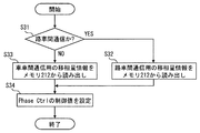
第6実施形態では、製造時、取り付け時など、通信前に図10に示す処理を行い、実際の通信時に図11に示す処理を行なう。図10において、ステップS1では、移相量情報を作業者が所定の入力装置から入力する。入力した移相量情報はメモリ212に記憶される(ステップS2)。 In the sixth embodiment, the process shown in FIG. 10 is performed before communication, such as during manufacture and attachment, and the process shown in FIG. 11 is performed during actual communication. In FIG. 10, in step S1, an operator inputs phase shift amount information from a predetermined input device. The input phase shift amount information is stored in the memory 212 (step S2).
通信時には、図11に示すように、移相量情報をメモリ212から読み出して(ステップS11)、その読み出した移相量情報に基づいて、移相量制御のための制御値を設定する(ステップS12)。この制御値を移相器140へ入力する。
At the time of communication, as shown in FIG. 11, phase shift amount information is read from the memory 212 (step S11), and a control value for phase shift amount control is set based on the read phase shift amount information (step S11). S12). This control value is input to the
(第7実施形態)
第7実施形態では、前述の図10、図11に代えて、図12、図13に示す処理を実行する。図12は、図10と同様、通信前に予め行なう。ステップS21では、路車間通信用の移相量情報を入力する。入力した路車間通信用の移相量情報はメモリ212に記憶される(ステップS22)。
(Seventh embodiment)
In the seventh embodiment, the processes shown in FIGS. 12 and 13 are executed instead of the processes shown in FIGS. As in FIG. 10, FIG. 12 is performed before communication. In step S21, phase shift amount information for road-to-vehicle communication is input. The input phase shift amount information for road-to-vehicle communication is stored in the memory 212 (step S22).
次いで、車車間通信用の移相量情報を入力する(ステップS23)。入力した車車間通信用の移相量情報もメモリ212に記憶される(ステップS24)。なお、路車間通信用の移相量情報および車車間通信用の移相量情報は、予め実験に基づいてどのような値がよいかを決定しておく。 Next, phase shift amount information for inter-vehicle communication is input (step S23). The input phase shift amount information for inter-vehicle communication is also stored in the memory 212 (step S24). Note that the values of the phase shift amount information for road-to-vehicle communication and the phase shift amount information for inter-vehicle communication are determined in advance based on experiments.
通信時には、図13に示すように、まず、路車間通信か否かを判断する(ステップS31)。この判断は、たとえば、送信する信号の種類により行なう。他車両に対する信号であればこの判断がNOになり、路側機に対する信号であればこの判断がYESになる。なお、送信する信号が定まる前に、種々の条件(たとえば、場所、受信信号の送信装置が車載機であるか路側機であるかなど)で、この判断を行なってもよい。 At the time of communication, as shown in FIG. 13, it is first determined whether or not it is road-to-vehicle communication (step S31). This determination is made based on, for example, the type of signal to be transmitted. If the signal is for another vehicle, the determination is NO, and if the signal is for a roadside machine, the determination is YES. Note that this determination may be made under various conditions (for example, whether the transmission device for receiving signals is an in-vehicle device or a roadside device) before a signal to be transmitted is determined.
路車間通信であれば(S31:YES)、路車間通信用の移相量情報をメモリ212から読み出す(ステップS32)。一方、車車間通信であれば(S31:NO)、路車間通信用の移相量情報をメモリ212から読み出す(ステップS33)。 If it is road-to-vehicle communication (S31: YES), phase shift amount information for road-to-vehicle communication is read from the memory 212 (step S32). On the other hand, if it is vehicle-to-vehicle communication (S31: NO), phase shift amount information for road-to-vehicle communication is read from the memory 212 (step S33).
ステップS32あるいはS33を実行したら、読み出した移相量情報に基づいて、移相量制御のための制御値を設定する(ステップS34)。 When step S32 or S33 is executed, a control value for phase shift amount control is set based on the read phase shift amount information (step S34).
このようにすれば、車車間通信の場合も、路車間通信の場合も、同じアンテナ110A、110Bを用いつつ、それぞれの通信に適した送信指向性で電波を送信することができる。
In this way, in the case of vehicle-to-vehicle communication and road-to-vehicle communication, it is possible to transmit radio waves with the transmission directivity suitable for each communication while using the
(第8実施形態)
第8実施形態では、前述の図10や図12に代えて図14に示す処理を実行し、図11や図13に代えて図15に示す処理を実行する。
(Eighth embodiment)
In the eighth embodiment, the process shown in FIG. 14 is executed instead of the above-described FIG. 10 and FIG. 12, and the process shown in FIG. 15 is executed instead of FIG.
図14において、ステップS41では、仰角大通信用の移相量情報を入力する。入力した仰角大通信用の移相量情報はメモリ212に記憶される(ステップS42)。ステップS43では、仰角小通信用の移相量情報を入力する。入力した仰角小通信用の移相量情報もメモリ212に記憶される(ステップS44)。なお、仰角大および仰角小は、一方が他方に対して仰角大あるいは小であることを意味し、仰角大通信用の移相量情報および仰角小通信用の移相量情報は、たとえば、図5に示す位相差30°、270°である。 In FIG. 14, in step S41, phase shift amount information for high elevation angle communication is input. The input phase shift amount information for large elevation angle communication is stored in the memory 212 (step S42). In step S43, phase shift amount information for small elevation angle communication is input. The input phase shift amount information for small elevation angle communication is also stored in the memory 212 (step S44). Note that large elevation angle and small elevation angle mean that one is larger or smaller than the other, and phase shift amount information for large elevation angle communication and phase shift amount information for small elevation angle communication are, for example, The phase difference shown in FIG. 5 is 30 ° and 270 °.
通信時には、図15に示すように、まず、CAN300とI/F213を介して車速情報を読み込む(ステップS51)。そして、その車速情報から、所定車速を超える高速走行中か否かを判断する(ステップS52)。
At the time of communication, as shown in FIG. 15, first, vehicle speed information is read through the
高速走行中と判断すれば(S52:YES)、ステップS53に進んで仰角小用の移相量情報をメモリ212から読み出す。一方、高速走行中でないと判断すれば(S52:NO)、ステップS54に進んで仰角大用の移相量情報をメモリ212から読み出す。
If it is determined that the vehicle is traveling at high speed (S52: YES), the process proceeds to step S53, and phase shift amount information for a small elevation angle is read from the
ステップS55では、ステップS53あるいはS54で読み出した移相量情報に基づいて、移相量制御のための制御値を設定する。なお、高速走行中か否かは市街地を走行中か否かを判断するために行なっている。高速走行中(市街地ではない場所を走行中)である場合に仰角小とし、低速走行中(市街地を走行中)は仰角大とするのは、市街地では仰角大のほうが良好に通信できることを実験により発見したからである。 In step S55, a control value for phase shift amount control is set based on the phase shift amount information read in step S53 or S54. Whether or not the vehicle is traveling at high speed is determined to determine whether or not the vehicle is traveling in an urban area. And elevation angle small when a high speed traveling (traveling in the location is not a city), the low-speed traveling (traveling in the urban area) is an elevation Dai, experiments that better elevation size can communicate well in city It was because it discovered by.
また、移相量情報を仰角大通信用と仰角小通信用の2種類に限定せず、仰角が異なる3種類以上の移相量情報をメモリ212に記憶しておき、それら3種類以上の移相量情報を車速に応じて設定してもよい。
Further, the phase shift amount information is not limited to two types for high elevation angle communication and small elevation angle communication, but three or more types of phase shift amount information with different elevation angles are stored in the
(第9実施形態)
第9実施形態では、第8実施形態おける図15に代えて図16を実行する。図14の処理は第9実施形態でも行なう。
(Ninth embodiment)
In the ninth embodiment, FIG. 16 is executed instead of FIG. 15 in the eighth embodiment. The process of FIG. 14 is also performed in the ninth embodiment.
通信時には、図16に示すように、まず、CAN300とI/F213を介してカメラセンサ情報を読み込む(ステップS61)。そして、そのカメラセンサ情報から、すぐ前方に大型車が存在するか(1台前の車が大型車であるか)を判断する(ステップS62)。
At the time of communication, as shown in FIG. 16, first, camera sensor information is read via the
前方に大型車が存在すると判断すれば(S62:YES)、ステップS63に進んで仰角大用の移相量情報をメモリ212から読み出す。一方、前方に大型車が存在しないと判断すれば(S62:NO)、ステップS64に進んで仰角小用の移相量情報をメモリ212から読み出す。
If it is determined that there is a large vehicle ahead (S62: YES), the process proceeds to step S63, and phase shift amount information for large elevation angle is read from the
ステップS65では、ステップS63あるいはS64で読み出した移相量情報に基づいて、移相量制御のための制御値を設定する。このようにすれば、前方に大型車が存在する場合にも、その大型車による電波の遮蔽の影響を抑制して良好な通信が行える。また、前方に大型車が存在しない場合には仰角小とするので、仰角大とする場合よりも通信距離を確保できる。 In step S65, a control value for phase shift amount control is set based on the phase shift amount information read in step S63 or S64. In this way, even when there is a large vehicle ahead, good communication can be performed while suppressing the influence of radio wave shielding by the large vehicle. Further, since the elevation angle is small when there is no large vehicle ahead, the communication distance can be secured as compared with the case where the elevation angle is large.
なお、第9実施形態でも、仰角が異なる3種類以上の移相量情報をメモリ212に記憶しておいてもよい。この場合、それら3種類以上の移相量情報を、前方車両の高さに応じて設定する。また、前方車両の高さに加えて前方車両までの距離も考慮し、前方車両の高さが高いほど、また、前方車両までの距離が近いほど、大きな仰角の移相量情報を用いるようにしてもよい。
In the ninth embodiment, three or more types of phase shift amount information having different elevation angles may be stored in the
(第10実施形態)
第10実施形態では、通信前に予め行なう処理として図17に示す処理を行なう。図17において、ステップS71では、無指向性型の移相量情報を入力する。入力した無指向性型の移相量情報はメモリ212に記憶される(ステップS72)。ステップS73では、前方指向性型の移相量情報を入力する。入力した前方指向性型の移相量情報もメモリ212に記憶される(ステップS74)。なお、無指向性型の移相量情報および前方指向性型の移相量情報は、たとえば、図4に示す位相差90°、180°である。
(10th Embodiment)
In the tenth embodiment, the processing shown in FIG. 17 is performed as processing performed in advance before communication. In FIG. 17, in step S71, omnidirectional phase shift amount information is input. The input omnidirectional phase shift amount information is stored in the memory 212 (step S72). In step S73, forward directivity type phase shift amount information is input. The inputted forward directivity type phase shift amount information is also stored in the memory 212 (step S74). Note that the non-directional type phase shift amount information and the forward directional type phase shift amount information are, for example, the phase differences of 90 ° and 180 ° shown in FIG.
通信時には、図18に示すように、まず、CAN300とI/F213を介して車速情報を読み込む(ステップS81)。そして、その車速情報をもとにして、高速道路走行中か否かを判断する(ステップS82)。なお、車速情報に代えて、地図情報と現在位置情報から高速道路走行中か否かを判断してもよい。
At the time of communication, as shown in FIG. 18, first, vehicle speed information is read via the
高速走行中と判断すれば(S82:YES)、ステップS83に進んで前方指向性型の移相量情報をメモリ212から読み出す。一方、高速走行中でないと判断すれば(S82:NO)、ステップS84に進んで無指向性型の移相量情報をメモリ212から読み出す。
If it is determined that the vehicle is traveling at high speed (S82: YES), the process proceeds to step S83, and the forward directivity type phase shift amount information is read from the
ステップS85では、ステップS83あるいはS84で読み出した移相量情報に基づいて、移相量制御のための制御値を設定する。高速道路を走行中である場合に前方指向性型とするのは、高速道路走行中は前後方向にしか通信対象(車両や路側機)が存在しないので、交差方向への電波送信は不要だからである。 In step S85, a control value for phase shift amount control is set based on the phase shift amount information read in step S83 or S84. When driving on an expressway, the forward directivity type is used because there is no communication target (vehicle or roadside machine) in the front-rear direction while driving on the expressway, so there is no need to transmit radio waves in the crossing direction. is there.
この第10実施形態では、高速道路走行中か否かで水平方向の指向性を変化させていることから、高速道路走行中も、高速道路以外を走行中も、良好な送信性能が確保できる。 In the tenth embodiment, since the directivity in the horizontal direction is changed depending on whether or not the vehicle is traveling on an expressway, good transmission performance can be ensured both when traveling on an expressway and when traveling on a road other than an expressway.
(第11実施形態)
第11実施形態では、製造時に図19に示す処理を行なう。図19において、ステップS91では、車両モデルX用の移相量情報を入力する。入力した車両モデルX用の移相量情報はメモリ212に記憶される(ステップS92)。ステップS93では、車両モデルY用の移相量情報を入力する。この車両モデルY用の移相量情報もメモリ212に記憶される(ステップS94)。さらに、車両モデルZ用の移相量情報も入力する(ステップS95)。この車両モデルZ用の移相量情報もメモリ212に記憶される(ステップS96)。なお、この図19では、3つの車両モデルX、Y、Zの移相量情報を入力、記憶しているが、2つ、あるいは、4つ以上の車両モデルの移相量情報を記憶するようにしてもよい。
(Eleventh embodiment)
In the eleventh embodiment, the process shown in FIG. In FIG. 19, in step S91, phase shift amount information for the vehicle model X is input. The input phase shift amount information for the vehicle model X is stored in the memory 212 (step S92). In step S93, phase shift amount information for the vehicle model Y is input. The phase shift amount information for the vehicle model Y is also stored in the memory 212 (step S94). Further, phase shift amount information for the vehicle model Z is also input (step S95). The phase shift amount information for the vehicle model Z is also stored in the memory 212 (step S96). In FIG. 19, phase shift amount information of three vehicle models X, Y, and Z is input and stored. However, phase shift amount information of two or four or more vehicle models is stored. It may be.
この実施形態では、実際の通信時に図20の処理を行なう。図20において、ステップS101では、CAN300とI/F213を介して車両モデル情報を読み込む。
In this embodiment, the processing of FIG. 20 is performed during actual communication. In FIG. 20, in step S101, vehicle model information is read via the
続いて、読み込んだ車両モデルが何であったかを判断する。読み込んだ車両モデルがXであればステップS103へ進み、車両モデルX用の移相量情報をメモリ212から読み出す。読み込んだ車両モデルがYであればステップS104へ進み、車両モデルY用の移相量情報をメモリ212から読み出す。読み込んだ車両モデルがZであればステップS105へ進み、車両モデルZ用の移相量情報をメモリ212から読み出す。
Subsequently, it is determined what the read vehicle model was. If the read vehicle model is X, the process proceeds to step S103, and the phase shift amount information for the vehicle model X is read from the
ステップS106では、ステップS103、104、105のいずれかで読み出した移相量情報に基づいて、移相量制御のための制御値を設定する。 In step S106, a control value for phase shift amount control is set based on the phase shift amount information read in any of steps S103, 104, and 105.
このようにすれば、車両モデルにより異なるルーフ傾斜に応じた適切な指向性を設定することができる。 If it does in this way, the appropriate directivity according to the roof inclination which changes with vehicle models can be set up.
以上、本発明の実施形態を説明したが、本発明は上述の実施形態に限定されるものではなく、次の実施形態も本発明の技術的範囲に含まれ、さらに、下記以外にも要旨を逸脱しない範囲内で種々変更して実施することができる。 As mentioned above, although embodiment of this invention was described, this invention is not limited to the above-mentioned embodiment, The following embodiment is also contained in the technical scope of this invention, and also the summary other than the following is also included. Various modifications can be made without departing from the scope.
たとえば、前述の実施形態では、2つのアンテナ110A、110Bは、車両前後方向の位置が相違し、且つ、上下方向の位置も相違していた。しかし、2つのアンテナを、上下方向の位置は同じとして前後方向の位置のみを異ならせてもよい(変形例1)。これ以外にも、2つのアンテナの相対的位置関係は種々変更してもよい。また、アンテナの数は3つ以上でもよい(変形例2)。また、前述の実施形態は車両用であったが、本発明は車両用以外にも適用できる。
For example, in the above-described embodiment, the two
1:車両用無線通信装置、 2:車両ルーフ、 100:アンテナモジュール、 110:アンテナ、 120:切り替え回路、 130:分配器、 134:切り替え制御部、 140:移相器、 160:パワーアンプ、 161:パワーアンプ、 200:ECU(制御部)、 212:メモリ(記憶部)、 220:通信チップ、 221:受信部、 222:受信部、 223:送信部、 224:ベースバンド部、 230:切り替え回路、 240:アンテナ切り替えスイッチ 1: wireless communication device for vehicle, 2: vehicle roof, 100: antenna module, 110: antenna, 120: switching circuit, 130: distributor, 134: switching control unit, 140: phase shifter, 160: power amplifier, 161 : Power amplifier, 200: ECU (control unit), 212: memory (storage unit), 220: communication chip, 221: reception unit, 222: reception unit, 223: transmission unit, 224: baseband unit, 230: switching circuit 240: Antenna selector switch
Claims (7)
前記複数のアンテナを用いてダイバーシティ受信する受信部(221、222)と、
送信部(223)と、
前記複数のアンテナに接続される切り替え回路(120A、120B)と、
前記切り替え回路と前記送信部とを接続する伝送線路に配置され、送信時には前記送信部から出力された信号を複数のアンテナに分配する分配器(130)と、
その分配器と前記複数のアンテナとをそれぞれ接続する複数の伝送線路のうちのいずれか少なくとも一つの伝送線路に設けられた移相器(140)と、
前記移相器の移相量を制御する制御部(200)とを備え、
車両に搭載されている無線通信装置であって、
車車間通信時であるか路車間通信時であるかを判断する通信種別判断手段(210、S31)と、
車車間通信時における前記移相器の移相量、および、路車間通信時における前記移相器の移相量を記憶した記憶部(212)とを備え、
前記制御部は、前記通信種別判断手段により車車間通信時と判断した場合には前記記憶部から車車間通信時の移相量を読み出して前記移相器の移相量を設定し、前記通信種別判断手段が路車間通信時と判断した場合には前記記憶部から路車間通信時の移相量を読み出して前記移相器の移相量を設定することを特徴とする無線通信装置。 A plurality of antennas (110A, 110B);
Receiving units (221, 222) for diversity reception using the plurality of antennas;
A transmission unit (223);
Switching circuits (120A, 120B) connected to the plurality of antennas;
A distributor (130) disposed on a transmission line connecting the switching circuit and the transmission unit, and distributing a signal output from the transmission unit to a plurality of antennas at the time of transmission;
A phase shifter (140) provided on at least one transmission line of a plurality of transmission lines respectively connecting the distributor and the plurality of antennas ;
A control unit (200) for controlling the amount of phase shift of the phase shifter,
A wireless communication device mounted on a vehicle,
A communication type determining means (210, S31) for determining whether the vehicle-to-vehicle communication or the road-to-vehicle communication is being performed;
A storage unit (212) that stores a phase shift amount of the phase shifter during vehicle-to-vehicle communication and a phase shift amount of the phase shifter during road-vehicle communication;
The control unit reads the phase shift amount at the time of inter-vehicle communication from the storage unit and sets the phase shift amount of the phase shifter when the communication type determination unit determines that the communication is between vehicles, and sets the phase shift amount of the phase shifter. A wireless communication apparatus, wherein when the type determining means determines that the road-to-vehicle communication is being performed, the phase shift amount during the road-to-vehicle communication is read from the storage unit and the phase shift amount of the phase shifter is set.
前記複数のアンテナを用いてダイバーシティ受信する受信部(221、222)と、
送信部(223)と、
前記複数のアンテナに接続される切り替え回路(120A、120B)と、
前記切り替え回路と前記送信部とを接続する伝送線路に配置され、送信時には前記送信部から出力された信号を複数のアンテナに分配する分配器(130)と、
その分配器と前記複数のアンテナとをそれぞれ接続する複数の伝送線路のうちのいずれか少なくとも一つの伝送線路に設けられた移相器(140)と、
前記移相器の移相量を制御する制御部(200)とを備え、
車両に搭載されている無線通信装置であって、
前記複数のアンテナは、車両の上下方向における位置が異なるように配置されており、
仰角が互いに異なる指向性とすることができる前記移相量を複数記憶するとともに、それぞれの移相量に対応する車両モデルを記憶した記憶部(212)と、
前記車両の車両モデルを取得する取得手段(210、S101)とを備え、
前記制御部は、前記取得手段が取得した車両モデルに対応する移相量を、前記記憶部から読みだして前記移相器の移相量を設定することを特徴とする無線通信装置。 A plurality of antennas (110A, 110B);
Receiving units (221, 222) for diversity reception using the plurality of antennas;
A transmission unit (223);
Switching circuits (120A, 120B) connected to the plurality of antennas;
A distributor (130) disposed on a transmission line connecting the switching circuit and the transmission unit, and distributing a signal output from the transmission unit to a plurality of antennas at the time of transmission;
A phase shifter (140) provided on at least one transmission line of a plurality of transmission lines respectively connecting the distributor and the plurality of antennas ;
A control unit (200) for controlling the amount of phase shift of the phase shifter,
A wireless communication device mounted on a vehicle,
The plurality of antennas are arranged so that positions in the vertical direction of the vehicle are different,
A storage unit (212) that stores a plurality of phase shift amounts that can have different directivities of elevation angles, and stores a vehicle model corresponding to each phase shift amount;
Obtaining means (210, S101) for obtaining a vehicle model of the vehicle,
The said control part reads the phase shift amount corresponding to the vehicle model which the said acquisition means acquired from the said memory | storage part, and sets the phase shift amount of the said phase shifter, The radio | wireless communication apparatus characterized by the above-mentioned.
車車間通信時であるか路車間通信時であるかを判断する通信種別判断手段(210、S31)と、
車車間通信時における前記移相器の移相量、および、路車間通信時における前記移相器の移相量を記憶した記憶部(212)とを備え、
前記制御部は、前記通信種別判断手段により車車間通信時と判断した場合には前記記憶部から車車間通信時の移相量を読み出して前記移相器の移相量を設定し、前記通信種別判断手段が路車間通信時と判断した場合には前記記憶部から路車間通信時の移相量を読み出して前記移相器の移相量を設定することを特徴とする無線通信装置。 In claim 2,
A communication type determining means (210, S31) for determining whether the vehicle-to-vehicle communication or the road-to-vehicle communication is being performed;
A storage unit (212) that stores a phase shift amount of the phase shifter during vehicle-to-vehicle communication and a phase shift amount of the phase shifter during road-vehicle communication;
The control unit reads the phase shift amount at the time of inter-vehicle communication from the storage unit and sets the phase shift amount of the phase shifter when the communication type determination unit determines that the communication is between vehicles, and sets the phase shift amount of the phase shifter. A wireless communication apparatus, wherein when the type determining means determines that the road-to-vehicle communication is being performed, the phase shift amount during the road-to-vehicle communication is read from the storage unit and the phase shift amount of the phase shifter is set.
前記複数のアンテナは、車両の上下方向における位置が異なるように配置されており、
電波を送信する複数の仰角に対応した複数の前記移相器の移相量を記憶した記憶部(212)を備え、
前記制御部は、前記記憶部に記憶されている複数の移相量から一つの移相量を選択して読み出して前記移相器の移相量を設定することを特徴とする無線通信装置。 In claim 1 ,
The plurality of antennas are arranged so that positions in the vertical direction of the vehicle are different,
A storage unit (212) storing a plurality of phase shift amounts of the plurality of phase shifters corresponding to a plurality of elevation angles for transmitting radio waves;
The control unit selects and reads one phase shift amount from a plurality of phase shift amounts stored in the storage unit, and sets the phase shift amount of the phase shifter.
前記複数のアンテナは、車両の前後方向における位置が異なるように配置されており、
水平面における指向性を互いに異なる指向性とすることができる前記移相量を複数記憶した記憶部(212)を備え、
前記制御部は、前記記憶部に記憶されている複数の移相量から一つの移相量を選択して読み出して前記移相器の移相量を設定することを特徴とする無線通信装置。 In claim 1 ,
The plurality of antennas are arranged so that positions in the front-rear direction of the vehicle are different,
A storage unit (212) that stores a plurality of the phase shift amounts capable of making the directivities in the horizontal plane different from each other,
The control unit selects and reads one phase shift amount from a plurality of phase shift amounts stored in the storage unit, and sets the phase shift amount of the phase shifter.
前記記憶部には、水平面における指向性が前記車両の前後方向となる移相量と、水平面における指向性が無指向性となる移相量とを記憶しており、
前記車両が走行している道路が高速道路であるか否かを判断する道路種別判断手段(210、S82)を備え、
前記制御部は、前記道路種別判断手段が高速道路を走行していると判断した場合には、前記記憶部から、水平面における指向性が前記車両の前後方向となる移相量を読み出して前記移相器の移相量を設定し、前記道路種別判断手段が高速道路を走行してないと判断した場合には、前記記憶部から、水平面における指向性が無指向性となる移相量を読み出して前記移相器の移相量を設定することを特徴とする無線通信装置。 In claim 5,
The storage unit stores a phase shift amount in which the directivity in the horizontal plane is the front-rear direction of the vehicle, and a phase shift amount in which the directivity in the horizontal plane is non-directional.
Road type judgment means (210, S82) for judging whether or not the road on which the vehicle is traveling is an expressway;
When the road type determination unit determines that the road type determination unit is traveling on an expressway, the control unit reads out the phase shift amount in which the directivity in the horizontal plane is the front-rear direction of the vehicle from the storage unit. When the phase shift amount of the phaser is set and the road type determination means determines that the vehicle is not traveling on the highway, the phase shift amount that makes the directivity in the horizontal plane non-directional is read from the storage unit. And a phase shift amount of the phase shifter is set.
前記複数のアンテナと前記分配器との間に、それぞれ増幅器(161A、161B)が設けられていることを特徴とする無線通信装置。 In any one of Claims 1-6 ,
An amplifier (161A, 161B) is provided between each of the plurality of antennas and the distributor.
Priority Applications (4)
| Application Number | Priority Date | Filing Date | Title |
|---|---|---|---|
| JP2012193248A JP5821812B2 (en) | 2012-09-03 | 2012-09-03 | Wireless communication device |
| US14/425,285 US9356812B2 (en) | 2012-09-03 | 2013-08-23 | Wireless communication apparatus |
| DE112013004323.8T DE112013004323T5 (en) | 2012-09-03 | 2013-08-23 | Wireless communication device |
| PCT/JP2013/004992 WO2014034068A1 (en) | 2012-09-03 | 2013-08-23 | Wireless communication apparatus |
Applications Claiming Priority (1)
| Application Number | Priority Date | Filing Date | Title |
|---|---|---|---|
| JP2012193248A JP5821812B2 (en) | 2012-09-03 | 2012-09-03 | Wireless communication device |
Publications (3)
| Publication Number | Publication Date |
|---|---|
| JP2014050028A JP2014050028A (en) | 2014-03-17 |
| JP2014050028A5 JP2014050028A5 (en) | 2014-12-25 |
| JP5821812B2 true JP5821812B2 (en) | 2015-11-24 |
Family
ID=50182906
Family Applications (1)
| Application Number | Title | Priority Date | Filing Date |
|---|---|---|---|
| JP2012193248A Active JP5821812B2 (en) | 2012-09-03 | 2012-09-03 | Wireless communication device |
Country Status (4)
| Country | Link |
|---|---|
| US (1) | US9356812B2 (en) |
| JP (1) | JP5821812B2 (en) |
| DE (1) | DE112013004323T5 (en) |
| WO (1) | WO2014034068A1 (en) |
Families Citing this family (3)
| Publication number | Priority date | Publication date | Assignee | Title |
|---|---|---|---|---|
| JP6206243B2 (en) * | 2014-02-21 | 2017-10-04 | 株式会社Soken | Collective antenna device |
| CN211209693U (en) | 2017-08-30 | 2020-08-07 | 株式会社友华 | Antenna device |
| JP6852707B2 (en) * | 2018-03-28 | 2021-03-31 | 株式会社デンソー | Communication device |
Family Cites Families (13)
| Publication number | Priority date | Publication date | Assignee | Title |
|---|---|---|---|---|
| JPH09200115A (en) * | 1996-01-23 | 1997-07-31 | Toshiba Corp | Method for controlling antenna directivity for radio base station in radio communication system and variable directivity antenna |
| JP2001345746A (en) * | 2000-06-05 | 2001-12-14 | Matsushita Electric Ind Co Ltd | Radio communication method as well as base station and terminal station performing radio communication |
| JP2005072782A (en) | 2003-08-21 | 2005-03-17 | Sony Corp | Antenna and receiver using the same |
| US20050122262A1 (en) * | 2003-10-31 | 2005-06-09 | Hoon Ahn | Electronically steerable array antenna for satellite TV |
| JP4322723B2 (en) * | 2004-03-30 | 2009-09-02 | 株式会社豊田中央研究所 | Directivity control device |
| EP1723695A1 (en) * | 2004-08-26 | 2006-11-22 | NTT DoCoMo, Inc. | Context-aware directional antenna |
| US8154386B2 (en) * | 2005-11-03 | 2012-04-10 | Lg Innotek Co., Ltd. | RFID reader and RFID system |
| JP4930591B2 (en) * | 2007-06-05 | 2012-05-16 | 富士通株式会社 | Transmission control method, inter-mobile station communication control method, radio base station, and mobile station |
| JP2009077015A (en) * | 2007-09-19 | 2009-04-09 | Toyota Central R&D Labs Inc | Inter-vehicle communication device and method |
| JP4606453B2 (en) * | 2007-11-20 | 2011-01-05 | 三菱電機株式会社 | OBE |
| JP5245522B2 (en) * | 2008-05-07 | 2013-07-24 | 富士通株式会社 | Radio resource allocation device, radio resource allocation system, and radio resource allocation method |
| JP5524714B2 (en) | 2010-05-26 | 2014-06-18 | 株式会社日本自動車部品総合研究所 | Diversity antenna |
| US8587418B2 (en) * | 2010-07-28 | 2013-11-19 | Honda Motor Co., Ltd. | Method of controlling a collision warning system using right of way |
-
2012
- 2012-09-03 JP JP2012193248A patent/JP5821812B2/en active Active
-
2013
- 2013-08-23 WO PCT/JP2013/004992 patent/WO2014034068A1/en active Application Filing
- 2013-08-23 DE DE112013004323.8T patent/DE112013004323T5/en not_active Withdrawn
- 2013-08-23 US US14/425,285 patent/US9356812B2/en active Active
Also Published As
| Publication number | Publication date |
|---|---|
| US9356812B2 (en) | 2016-05-31 |
| DE112013004323T5 (en) | 2015-06-03 |
| WO2014034068A1 (en) | 2014-03-06 |
| JP2014050028A (en) | 2014-03-17 |
| US20150229500A1 (en) | 2015-08-13 |
Similar Documents
| Publication | Publication Date | Title |
|---|---|---|
| KR102566887B1 (en) | Antenna systems mounted on vehicles | |
| KR20180137992A (en) | V2X Antenna and V2X Antenna system having the same | |
| US10074895B2 (en) | Collective antenna device | |
| KR102578394B1 (en) | Antenna system mounted on vehicle | |
| KR102552305B1 (en) | Broadband antennas deployed in vehicles | |
| AU2016269545B2 (en) | Multiband, monopole antenna assembly | |
| JP2009124577A (en) | Composite antenna | |
| JP5907139B2 (en) | Wireless communication device | |
| JP5821812B2 (en) | Wireless communication device | |
| JP5524714B2 (en) | Diversity antenna | |
| JP2006050533A (en) | Antenna device | |
| CN114122722A (en) | Vehicle-mounted adaptive enhanced antenna control system and method | |
| US20220384955A1 (en) | Antenna system mounted on vehicle | |
| CN110546761A (en) | Super-directional array of volumetric antenna elements for wireless device applications | |
| KR101618126B1 (en) | Diversity antenna of integrated type for cooperative control communication | |
| CN115347929A (en) | Vehicle-mounted equipment antenna switching method and system | |
| JP2004304542A (en) | Dsrc on-vehicle equipment | |
| JP2007110390A (en) | High-frequency glass antenna for automobile | |
| JP5796159B2 (en) | Vehicle antenna device | |
| KR20220106111A (en) | Vehicle-mounted antenna system | |
| WO2021060070A1 (en) | Roadside device and traffic communication system | |
| KR102165727B1 (en) | Directional antenna | |
| CZ2013297A3 (en) | Method of turning directional radio antenna located on a vehicle | |
| JP2005175557A (en) | On-vehicle antenna system | |
| JP2005151230A (en) | Phase difference feed antenna |
Legal Events
| Date | Code | Title | Description |
|---|---|---|---|
| A521 | Request for written amendment filed |
Free format text: JAPANESE INTERMEDIATE CODE: A523 Effective date: 20141106 |
|
| A621 | Written request for application examination |
Free format text: JAPANESE INTERMEDIATE CODE: A621 Effective date: 20150311 |
|
| A131 | Notification of reasons for refusal |
Free format text: JAPANESE INTERMEDIATE CODE: A131 Effective date: 20150630 |
|
| A521 | Request for written amendment filed |
Free format text: JAPANESE INTERMEDIATE CODE: A523 Effective date: 20150819 |
|
| TRDD | Decision of grant or rejection written | ||
| A01 | Written decision to grant a patent or to grant a registration (utility model) |
Free format text: JAPANESE INTERMEDIATE CODE: A01 Effective date: 20150908 |
|
| A61 | First payment of annual fees (during grant procedure) |
Free format text: JAPANESE INTERMEDIATE CODE: A61 Effective date: 20150921 |
|
| R150 | Certificate of patent or registration of utility model |
Ref document number: 5821812 Country of ref document: JP Free format text: JAPANESE INTERMEDIATE CODE: R150 |
|
| R250 | Receipt of annual fees |
Free format text: JAPANESE INTERMEDIATE CODE: R250 |
|
| R250 | Receipt of annual fees |
Free format text: JAPANESE INTERMEDIATE CODE: R250 |
|
| R250 | Receipt of annual fees |
Free format text: JAPANESE INTERMEDIATE CODE: R250 |
|
| R250 | Receipt of annual fees |
Free format text: JAPANESE INTERMEDIATE CODE: R250 |
|
| R250 | Receipt of annual fees |
Free format text: JAPANESE INTERMEDIATE CODE: R250 |