JP5820271B2 - Retractor cannula system and related methods for spinal access and visualization - Google Patents
Retractor cannula system and related methods for spinal access and visualization Download PDFInfo
- Publication number
- JP5820271B2 JP5820271B2 JP2011532338A JP2011532338A JP5820271B2 JP 5820271 B2 JP5820271 B2 JP 5820271B2 JP 2011532338 A JP2011532338 A JP 2011532338A JP 2011532338 A JP2011532338 A JP 2011532338A JP 5820271 B2 JP5820271 B2 JP 5820271B2
- Authority
- JP
- Japan
- Prior art keywords
- retractor
- retractor assembly
- tissue
- tubular body
- cannula device
- Prior art date
- Legal status (The legal status is an assumption and is not a legal conclusion. Google has not performed a legal analysis and makes no representation as to the accuracy of the status listed.)
- Expired - Fee Related
Links
Images


Classifications
-
- A—HUMAN NECESSITIES
- A61—MEDICAL OR VETERINARY SCIENCE; HYGIENE
- A61B—DIAGNOSIS; SURGERY; IDENTIFICATION
- A61B17/00—Surgical instruments, devices or methods, e.g. tourniquets
- A61B17/34—Trocars; Puncturing needles
- A61B17/3417—Details of tips or shafts, e.g. grooves, expandable, bendable; Multiple coaxial sliding cannulas, e.g. for dilating
-
- A—HUMAN NECESSITIES
- A61—MEDICAL OR VETERINARY SCIENCE; HYGIENE
- A61B—DIAGNOSIS; SURGERY; IDENTIFICATION
- A61B10/00—Other methods or instruments for diagnosis, e.g. instruments for taking a cell sample, for biopsy, for vaccination diagnosis; Sex determination; Ovulation-period determination; Throat striking implements
- A61B10/02—Instruments for taking cell samples or for biopsy
- A61B10/06—Biopsy forceps, e.g. with cup-shaped jaws
-
- A—HUMAN NECESSITIES
- A61—MEDICAL OR VETERINARY SCIENCE; HYGIENE
- A61B—DIAGNOSIS; SURGERY; IDENTIFICATION
- A61B1/00—Instruments for performing medical examinations of the interior of cavities or tubes of the body by visual or photographical inspection, e.g. endoscopes; Illuminating arrangements therefor
- A61B1/313—Instruments for performing medical examinations of the interior of cavities or tubes of the body by visual or photographical inspection, e.g. endoscopes; Illuminating arrangements therefor for introducing through surgical openings, e.g. laparoscopes
- A61B1/3135—Instruments for performing medical examinations of the interior of cavities or tubes of the body by visual or photographical inspection, e.g. endoscopes; Illuminating arrangements therefor for introducing through surgical openings, e.g. laparoscopes for examination of the epidural or the spinal space
-
- A—HUMAN NECESSITIES
- A61—MEDICAL OR VETERINARY SCIENCE; HYGIENE
- A61B—DIAGNOSIS; SURGERY; IDENTIFICATION
- A61B17/00—Surgical instruments, devices or methods, e.g. tourniquets
- A61B17/02—Surgical instruments, devices or methods, e.g. tourniquets for holding wounds open; Tractors
- A61B17/0218—Surgical instruments, devices or methods, e.g. tourniquets for holding wounds open; Tractors for minimally invasive surgery
-
- A—HUMAN NECESSITIES
- A61—MEDICAL OR VETERINARY SCIENCE; HYGIENE
- A61B—DIAGNOSIS; SURGERY; IDENTIFICATION
- A61B17/00—Surgical instruments, devices or methods, e.g. tourniquets
- A61B17/00234—Surgical instruments, devices or methods, e.g. tourniquets for minimally invasive surgery
- A61B2017/00238—Type of minimally invasive operation
- A61B2017/00261—Discectomy
-
- A—HUMAN NECESSITIES
- A61—MEDICAL OR VETERINARY SCIENCE; HYGIENE
- A61B—DIAGNOSIS; SURGERY; IDENTIFICATION
- A61B17/00—Surgical instruments, devices or methods, e.g. tourniquets
- A61B17/00234—Surgical instruments, devices or methods, e.g. tourniquets for minimally invasive surgery
- A61B2017/00292—Surgical instruments, devices or methods, e.g. tourniquets for minimally invasive surgery mounted on or guided by flexible, e.g. catheter-like, means
- A61B2017/003—Steerable
-
- A—HUMAN NECESSITIES
- A61—MEDICAL OR VETERINARY SCIENCE; HYGIENE
- A61B—DIAGNOSIS; SURGERY; IDENTIFICATION
- A61B17/00—Surgical instruments, devices or methods, e.g. tourniquets
- A61B2017/00831—Material properties
- A61B2017/00902—Material properties transparent or translucent
- A61B2017/00907—Material properties transparent or translucent for light
-
- A—HUMAN NECESSITIES
- A61—MEDICAL OR VETERINARY SCIENCE; HYGIENE
- A61B—DIAGNOSIS; SURGERY; IDENTIFICATION
- A61B17/00—Surgical instruments, devices or methods, e.g. tourniquets
- A61B17/32—Surgical cutting instruments
- A61B2017/320064—Surgical cutting instruments with tissue or sample retaining means
-
- A—HUMAN NECESSITIES
- A61—MEDICAL OR VETERINARY SCIENCE; HYGIENE
- A61B—DIAGNOSIS; SURGERY; IDENTIFICATION
- A61B17/00—Surgical instruments, devices or methods, e.g. tourniquets
- A61B17/34—Trocars; Puncturing needles
- A61B17/3417—Details of tips or shafts, e.g. grooves, expandable, bendable; Multiple coaxial sliding cannulas, e.g. for dilating
- A61B2017/3419—Sealing means between cannula and body
-
- A—HUMAN NECESSITIES
- A61—MEDICAL OR VETERINARY SCIENCE; HYGIENE
- A61B—DIAGNOSIS; SURGERY; IDENTIFICATION
- A61B5/00—Measuring for diagnostic purposes; Identification of persons
- A61B5/0059—Measuring for diagnostic purposes; Identification of persons using light, e.g. diagnosis by transillumination, diascopy, fluorescence
- A61B5/0082—Measuring for diagnostic purposes; Identification of persons using light, e.g. diagnosis by transillumination, diascopy, fluorescence adapted for particular medical purposes
- A61B5/0084—Measuring for diagnostic purposes; Identification of persons using light, e.g. diagnosis by transillumination, diascopy, fluorescence adapted for particular medical purposes for introduction into the body, e.g. by catheters
-
- A—HUMAN NECESSITIES
- A61—MEDICAL OR VETERINARY SCIENCE; HYGIENE
- A61B—DIAGNOSIS; SURGERY; IDENTIFICATION
- A61B8/00—Diagnosis using ultrasonic, sonic or infrasonic waves
- A61B8/12—Diagnosis using ultrasonic, sonic or infrasonic waves in body cavities or body tracts, e.g. by using catheters
-
- A—HUMAN NECESSITIES
- A61—MEDICAL OR VETERINARY SCIENCE; HYGIENE
- A61B—DIAGNOSIS; SURGERY; IDENTIFICATION
- A61B90/00—Instruments, implements or accessories specially adapted for surgery or diagnosis and not covered by any of the groups A61B1/00 - A61B50/00, e.g. for luxation treatment or for protecting wound edges
- A61B90/36—Image-producing devices or illumination devices not otherwise provided for
- A61B90/361—Image-producing devices, e.g. surgical cameras
Description
(関連出願の相互参照)
本願は、米国仮特許出願第61/106,914号(2008年10月20日出願)の米国特許法第119条第(e)項の優先権の利益を主張し、この出願の開示は、その全体が本明細書に参考として援用される。本願は、また、米国特許出願第12/199,706号(2008年8月27日出願)に関連し、この出願は、その全体が本明細書に参考として援用される。
(Cross-reference of related applications)
This application claims the benefit of priority of US Patent Section 119 (e) of US Provisional Patent Application No. 61 / 106,914 (filed October 20, 2008), the disclosure of which is The entirety of which is incorporated herein by reference. This application is also related to US patent application Ser. No. 12 / 199,706 (filed Aug. 27, 2008), which is hereby incorporated by reference in its entirety.
(背景)
損傷した椎間板は、一般的に、相当な治療期間の床上安静、理学療法、活動の変更、および鎮痛剤によって治療される。損傷した椎間板を修復し、損傷した椎間板の外科的除去を回避しようとする多くの治療が存在する。例えば、椎間板除圧術は、髄核を摘出するかまたは収縮させることにより、繊維輪および神経への圧力を減圧および減少させるために使用される手技である。より侵襲性の低い顕微鏡下腰椎椎間板摘出術および自動経皮的腰椎椎間板摘出術は、繊維輪内に横方向に挿入した針を通して吸引することにより椎間板の髄核を摘出する。別の手技は、椎間板の変性を治療、遅延、または予防するために、椎間板増強デバイスを移植することを有する。増強とは、(1)椎間板ヘルニアの修復、損傷した繊維輪の支持、および繊維輪断裂の閉鎖を含む繊維輪の増強と、(2)髄核への材料の付加または除去を含む髄核の増強の両方を意味する。観血的アプローチを含む従来の治療デバイスおよび技術の多くは、蛍光透視による誘導下で椎間板の一部を穿刺するために筋肉の切開または経皮的手技を有するが、直接的可視化を用いない。いくつかの治療もまた、推測される損傷領域に薬物を注射すること、または癒着を溶解させることによって、椎間板起因の疼痛を減少させようとする。しかしながら、これらのデバイスもまた、外科医にとっての触覚、または、外科医が周囲の組織を傷付けることなく操作できるという点においては、提供するものはほとんどない。一般に、これらの従来システムは、椎間板に到達するためには外部からの可視化に依存するので、任意の種類のリアルタイムの搭載型可視化能力を持たない。
(background)
Injured discs are generally treated with bed rest, physical therapy, activity changes, and analgesics for a substantial treatment period. There are many therapies that attempt to repair a damaged disc and avoid surgical removal of the damaged disc. For example, intervertebral disc decompression is a procedure used to reduce and reduce pressure on the annulus and nerves by removing or constricting the nucleus pulposus. Less invasive microscopic lumbar discectomy and automated percutaneous lumbar discectomy remove the nucleus pulposus of the disc by aspiration through a needle inserted laterally into the annulus fibrosus. Another procedure involves implanting a disc augmentation device to treat, delay, or prevent disc degeneration. Augmentation includes (1) augmentation of the annulus including repair of herniated disc, support of damaged annulus fibrosus, and closure of annulus fibrosus and (2) nucleus pulposus including addition or removal of material to the nucleus pulposus. It means both enhancement. Many of the conventional treatment devices and techniques, including an open approach, have a muscular incision or percutaneous procedure to puncture a portion of the disc under fluoroscopic guidance, but do not use direct visualization. Some treatments also attempt to reduce discogenic pain by injecting drugs into the suspected damaged area or dissolving the adhesions. However, these devices also offer little in the sense of touch for the surgeon or in that the surgeon can operate without damaging the surrounding tissue. In general, these conventional systems do not have any kind of real-time on-board visualization capability because they rely on external visualization to reach the intervertebral disc.
背痛を正確に診断することは、多くの場合、予想よりも困難であって、詳細な患者の病歴および物理的検査だけではなく、いくつかの診断試験の組み合わせを有する場合が多い。大きな問題は、脊椎の種々の構成要素が複雑であること、そして個々の患者が経験する身体症状が広範囲に及ぶことである。また、硬膜外は、脂肪、結合組織、リンパ管、動脈、静脈、血液、および脊髄神経根等の種々の要素を含む。これらの解剖学的要素は、その中に挿入される任意の器具またはデバイスの周囲において崩壊する傾向があるので、硬膜外領域内で病状を治療あるいは診断を行うことを困難にする。このことにより、硬膜外における可視性が減少させられ、デバイスを挿入する際に神経根に不注意による損傷を生じさせる可能性がある。また、可視化デバイスの挿入は、視認能力を妨害または減少させる結果になり得る。このように、硬膜外における多くの解剖学的要素が、硬膜外に挿入される任意のアクセス、可視化、診断、または治療デバイスの挿入、移動、および視認能力を制限する可能性がある。 Accurate diagnosis of back pain is often more difficult than expected and often has a combination of several diagnostic tests, as well as a detailed patient history and physical examination. The major problem is the complexity of the various components of the spine and the wide range of physical symptoms experienced by individual patients. Epidural also includes various elements such as fat, connective tissue, lymphatic vessels, arteries, veins, blood, and spinal nerve roots. These anatomical elements tend to collapse around any instrument or device inserted therein, making it difficult to treat or diagnose a medical condition within the epidural region. This reduces the epidural visibility and can cause inadvertent damage to the nerve root when the device is inserted. Also, the insertion of the visualization device can result in disturbing or reducing the viewing ability. Thus, many epidural anatomical elements can limit the ability to insert, move, and view any access, visualization, diagnostic, or treatment device that is inserted epidurally.
本明細書のいくつかの実施形態は、脊椎へのアクセスおよび視覚化ならびに関連治療方法のためのカニューレ開創器システムに関する。いくつかの実施例では、開創器アセンブリは、作業空間を創出するために使用されてもよく、および/または組織を変位あるいは解離させるために使用され得る非外傷的構成を有する。いくつかのさらに実施例では、開創器アセンブリは、より大きな可視化視野および作業空間を創出するように開放され得る、カニューレの遠位端を中心として、一式の可動要素または顎部を備えてもよい。カニューレ内に位置する内視鏡および種々の療法ツールは、顎部が開放されたまま、またはいくつかの事例では、顎部が閉鎖位置にあるときに使用されてもよい。本明細書に説明されるデバイスおよび方法は、例えば、繊維輪修復、ヘルニア椎間板の切除、神経組織の除神経、または脊椎から骨材料の除去を行うために使用されてもよい。また、デバイスおよび方法は、薬剤および/または細胞あるいは組織療法剤を送達すること、椎間板変性および骨変性を診断すること、脊椎狭窄を治療すること、ならびに髄核減圧または椎間板増強を行うために使用されてもよい。 Some embodiments herein relate to a cannula retractor system for spine access and visualization and related treatment methods. In some examples, the retractor assembly may be used to create a working space and / or has an atraumatic configuration that may be used to displace or dissociate tissue. In some further examples, the retractor assembly may comprise a set of movable elements or jaws about the distal end of the cannula that can be opened to create a larger visualization field of view and workspace. . An endoscope located within the cannula and various therapy tools may be used when the jaw is left open or, in some cases, when the jaw is in a closed position. The devices and methods described herein may be used, for example, to perform annulus repair, herniated disc resection, nerve tissue denervation, or removal of bone material from the spine. Devices and methods are also used to deliver drugs and / or cells or tissue therapy agents, diagnose disc degeneration and bone degeneration, treat spinal stenosis, and perform nucleus pulposus decompression or disc augmentation May be.
一実施形態では、開創器カニューレデバイスは、管状体の遠位端に位置する開創器アセンブリを有する管状体を備えてもよい。管状体は、内視鏡または他の可視化システムを保持するように構成される少なくとも1つの内腔を有してもよく、開創器アセンブリは、第1の閉鎖構成と、第2の開放構成とを備えてもよい。いくつかの実施形態では、少なくとも1つの内腔は、内視鏡システムを取外し可能に受容するように構成されてもよい。また、開創器カニューレデバイスは、内視鏡システムを備えてもよい。一実施形態では、開創器アセンブリは、少なくとも1つの可動要素を備え、少なくとも1つの可動要素は、湾曲表面を有する。少なくとも1つの可動要素の湾曲表面は、第1の接線を有する第1の点と、第1の接線に垂直な第2の接線を有する第2の点とを備えてもよい。いくつかの実施形態では、可動要素の各々の湾曲表面は、開創器カニューレデバイスの縦軸の周囲に均一に配向されることにより、第1の閉鎖構成において、概して曲線状先端を形成してもよい。他の実施形態では、可動要素の各々の湾曲表面は、開創器カニューレデバイスの縦軸の周囲に不均一に配向されることにより、第1の閉鎖構成において、先細先端を形成してもよい。いくつかの実施形態では、先細先端は、線状の先細領域を備える。ある実施形態では、少なくとも1つの可動要素の湾曲表面は、開創器カニューレデバイスの縦軸の周囲に、不均一かつ非対称的に配向され、角度付き先端を形成する。いくつかの実施形態では、角度付き先端は、開創器アセンブリの縦方向中線を横断して配向されてもよい。いくつかの実施形態では、少なくとも1つの可動要素は、光学的に透明な材料を備えてもよい。開創器アセンブリのいくつかの実施形態は、少なくとも2つの可動要素を備えてもよい。 In one embodiment, the retractor cannula device may comprise a tubular body having a retractor assembly located at the distal end of the tubular body. The tubular body may have at least one lumen configured to hold an endoscope or other visualization system, and the retractor assembly includes a first closed configuration, a second open configuration, May be provided. In some embodiments, the at least one lumen may be configured to removably receive an endoscopic system. The retractor cannula device may also comprise an endoscope system. In one embodiment, the retractor assembly comprises at least one movable element, and the at least one movable element has a curved surface. The curved surface of the at least one movable element may comprise a first point having a first tangent and a second point having a second tangent perpendicular to the first tangent. In some embodiments, each curved surface of the movable element may be uniformly oriented around the longitudinal axis of the retractor cannula device to form a generally curved tip in the first closed configuration. Good. In other embodiments, each curved surface of the movable element may be non-uniformly oriented around the longitudinal axis of the retractor cannula device to form a tapered tip in the first closed configuration. In some embodiments, the tapered tip comprises a linear tapered region. In certain embodiments, the curved surface of the at least one movable element is non-uniformly and asymmetrically oriented around the longitudinal axis of the retractor cannula device to form an angled tip. In some embodiments, the angled tip may be oriented across the longitudinal midline of the retractor assembly. In some embodiments, the at least one movable element may comprise an optically transparent material. Some embodiments of the retractor assembly may comprise at least two movable elements.
開創器カニューレデバイスのいくつかの実施形態では、デバイスの縦軸に垂直な開創器アセンブリの断面は、非円形構成を備えてもよい。いくつかの実施形態では、デバイスの縦軸に垂直な開創器アセンブリの断面は、少なくとも1つの線状の領域を備えてもよい。少なくとも1つの可動要素を備える、開創器アセンブリのいくつかの実施形態では、少なくとも1つの可動要素は、凸状外側表面を備えてもよい。いくつかの実施形態では、少なくとも1つの可動要素は、凹状内側表面を備えてもよい。 In some embodiments of the retractor cannula device, the cross-section of the retractor assembly perpendicular to the longitudinal axis of the device may comprise a non-circular configuration. In some embodiments, the cross-section of the retractor assembly perpendicular to the longitudinal axis of the device may comprise at least one linear region. In some embodiments of the retractor assembly comprising at least one movable element, the at least one movable element may comprise a convex outer surface. In some embodiments, the at least one movable element may comprise a concave inner surface.
開創器カニューレデバイスのいくつかの実施形態では、開創器アセンブリは、少なくとも1つの可動要素と、少なくとも1つの定着要素と、を備えてもよく、可動および定着要素は、光学的に透明な材料を備えてもよい。一実施形態では、開創器アセンブリが第1の閉鎖構成にある時、少なくとも1つの可動要素および少なくとも1つの定着要素は、側部開口を形成してもよい。いくつかの実施形態では、少なくとも1つの定着要素は、管状体の遠位にあって、デバイスの縦軸と平行に配向されてもよい。 In some embodiments of the retractor cannula device, the retractor assembly may comprise at least one movable element and at least one anchoring element, the movable and anchoring element comprising an optically transparent material. You may prepare. In one embodiment, when the retractor assembly is in the first closed configuration, the at least one movable element and the at least one anchoring element may form a side opening. In some embodiments, the at least one anchoring element may be distal to the tubular body and oriented parallel to the longitudinal axis of the device.
開創器カニューレデバイスのいくつかの実施形態は、管状体の近位端にハンドルをさらに備えてもよい。ハンドルは、旋回部材と、デバイス係止部材と、を備えてもよい。いくつかの実施形態では、ハンドルは、旋回部材の移動を制限するように構成される、旋回部材係止部をさらに備えてもよい。また、ハンドルのいくつかの実施形態は、旋回部材の作動力を設定するための抵抗機構を備えてもよい。いくつかの実施形態では、デバイス係止機構は、システムを固定するように構成されてもよい。ハンドルのいくつかの実施形態は、1つ以上のポートを備えてもよい。ハンドルのいくつかの実施形態は、加えて、または代替として、1つ以上の内腔を備えてもよい。一実施形態では、少なくとも1つのポートは、洗浄ポートとして構成されてもよく、および/または少なくとも1つ以上のポートは、内視鏡システムを保持するように構成される、少なくとも1つの内腔と連通している可視化ポートであってもよい。 Some embodiments of the retractor cannula device may further comprise a handle at the proximal end of the tubular body. The handle may include a pivot member and a device locking member. In some embodiments, the handle may further comprise a pivot member lock configured to limit movement of the pivot member. Some embodiments of the handle may also include a resistance mechanism for setting the actuation force of the pivot member. In some embodiments, the device locking mechanism may be configured to secure the system. Some embodiments of the handle may comprise one or more ports. Some embodiments of the handle may additionally or alternatively include one or more lumens. In one embodiment, at least one port may be configured as an irrigation port and / or at least one or more ports are configured to hold an endoscopic system and at least one lumen It may be a visualization port that communicates.
一実施形態では、脊椎の一部にアクセスする方法は、直接的可視化能力を有する器具によって、脊椎の一部に経皮的にアプローチするステップと、器具を使用して、脊椎の一部へのアクセスを提供するステップと、器具を使用して、脊椎の一部を中心として、デバイスを配置するステップと、を含む。さらなる実施形態では、器具は、開創器アセンブリを備えてもよく、方法は、閉鎖構成にある開創器アセンブリを脊椎領域まで通過させるステップと、開創器アセンブリを開放構成に作動させるステップとを含んでもよい。別の実施形態では、開創器アセンブリは、身体の内側または外側で使用される撮像モダリティによって、構造の可視化を増強するための材料またはマーカを備えてもよい。また、診断デバイス、療法送達デバイス、刺激デバイス、または薬学療法デバイスが、器具内および脊椎領域に挿入されてもよい。別の実施形態では、方法は、器具の直接的可視化能力を使用して、デバイスを移植するステップを含む。さらに他の実施形態では、方法は、脊椎硬膜外腔、繊維輪、繊維輪層、椎間板髄核、面関節、尖孔、または脊椎筋組織等、脊椎の一部へのアクセスを提供するステップを含む。さらに別の実施形態では、また、方法は、蛍光透視法、磁気共鳴映像法、および/またはコンピュータ断層撮影法等、身体外に位置する撮像モダリティから可視化情報を受信するステップを含む。さらに他の実施形態では、方法は、器具の直接的可視化能力を使用して、脊椎神経根、脊髄硬膜、および神経組織と他の組織との間で器具を操作するステップ、および/または脊椎神経根あるいは他の軟組織を非外傷的に操作するステップを含む。さらに別の実施形態では、方法は、器具を使用して、椎間板増強デバイス、髄核増強デバイス、または椎間板切除デバイスを送達するステップを含む。別の実施形態では、器具は、診断目的のために使用されてもよい。 In one embodiment, a method for accessing a portion of a spine includes the steps of percutaneously approaching the portion of the spine with an instrument having direct visualization capability and using the instrument to access the portion of the spine. Providing access and using the instrument to position the device about a portion of the spine. In further embodiments, the instrument may comprise a retractor assembly, and the method may include passing the retractor assembly in a closed configuration to the spinal region and activating the retractor assembly to an open configuration. Good. In another embodiment, the retractor assembly may comprise materials or markers to enhance the visualization of the structure depending on the imaging modality used inside or outside the body. A diagnostic device, therapy delivery device, stimulation device, or pharmaceutical therapy device may also be inserted into the instrument and into the spinal region. In another embodiment, the method includes implanting the device using the instrument's direct visualization capabilities. In yet other embodiments, the method provides access to a portion of the spine, such as the spinal epidural space, annulus fibrosus, annulus fibrosus, disc nucleus pulposus, facet joint, apex, or spinal muscle tissue. including. In yet another embodiment, the method also includes receiving visualization information from an imaging modality located outside the body, such as fluoroscopy, magnetic resonance imaging, and / or computed tomography. In still other embodiments, the method uses the instrument's direct visualization capabilities to manipulate the instrument between the spinal nerve root, spinal dura mater, and nerve tissue and other tissues, and / or the spine. Atraumatically manipulating the nerve root or other soft tissue. In yet another embodiment, the method includes using an instrument to deliver a disc augmentation device, nucleus pulposus enhancement device, or discectomy device. In another embodiment, the instrument may be used for diagnostic purposes.
一実施形態において、開創器カニューレシステムは、閉鎖構成にあるとき、実質的に曲線状または湾曲幾何学形状を有する、少なくとも2つの相互係止顎部を備えてもよい。標的部位を中心として、開創器カニューレシステムを配置後、開創器アセンブリの顎部は、開放構成に留置されてもよく、作業空間を創出するように、組織を解離および/または変位させるための非外傷的ツールとして使用され、それによって、他の周囲構造の可視化を向上させてもよい。一実施形態では、開創器アセンブリは、開創器アセンブリの遠位先端が、閉塞性組織を内視鏡から離れるように押動させ、開創器アセンブリの遠位先端が、内視鏡と治療される標的部位との間に、視野の奥行を提供し得るように、前方視構造である。 In one embodiment, the retractor cannula system may comprise at least two interlocking jaws having a substantially curved or curved geometry when in the closed configuration. After placement of the retractor cannula system about the target site, the jaws of the retractor assembly may be placed in an open configuration and non-displaced to dissociate and / or displace the tissue to create a working space. It may be used as a traumatic tool, thereby improving the visualization of other surrounding structures. In one embodiment, the retractor assembly causes the distal tip of the retractor assembly to push the occlusive tissue away from the endoscope and the distal tip of the retractor assembly is treated with the endoscope. It is a forward view structure so that the depth of the visual field can be provided between the target site.
一実施形態は、開創器カニューレデバイスを対象とするものであって、多内腔伸長シャフトと、シャフトの遠位端に取着される、開創器アセンブリと、を備え、開創器アセンブリは、伸長シャフトの遠位区画に旋回可能に連結され、第1の閉鎖構成および第2の開放構成が可能な少なくとも2つの顎部を備え、第2の開放構成は、組織を変位させ、視野を拡張し、および/または作業視野を維持してもよい。一実施形態では、開創器アセンブリの顎部の顎部は、閉鎖構成にあるとき、曲線形状または先細形状の先端を形成する。他の実施形態では、開創器アセンブリは、種々の他の形状、先細、または非先細のいずれかを有してもよい。ある実施形態では、顎部は、光学的に不透明な材料または光学的に透明な材料から成ってもよい。いくつかの実施例では、光学的に透明な開創器アセンブリを有する、伸長シャフト内の内視鏡または光ファイバ線は、顎部が開放および閉鎖構成のいずれかにある時、周囲組織を可視化するために使用されてもよい。 One embodiment is directed to a retractor cannula device comprising a multi-lumen elongate shaft and a retractor assembly attached to a distal end of the shaft, the retractor assembly elongate A pivotally connected to the distal section of the shaft and comprising at least two jaws capable of a first closed configuration and a second open configuration, wherein the second open configuration displaces tissue and expands the field of view. And / or maintain a working field of view. In one embodiment, the jaws of the jaws of the retractor assembly form a curved or tapered tip when in the closed configuration. In other embodiments, the retractor assembly may have any of a variety of other shapes, tapered or non-tapered. In certain embodiments, the jaws may be made of an optically opaque material or an optically transparent material. In some embodiments, an endoscope or fiber optic line in an elongate shaft with an optically clear retractor assembly visualizes surrounding tissue when the jaw is in either an open and closed configuration May be used for
また、いくつかの実施形態は、近位部分および遠位部分と、1つ以上の内腔と、を有する、開創器アセンブリカテーテルを備えてもよく、該近位部分は、3つの別個の内腔を含有し、該内腔の1つは、内視鏡の通過を可能にするために好適であって、該内腔の1つは、吸引および/または潅注のために好適であって、他の内腔は、療法器具の通過あるいは薬物の注入を可能にするために好適である。他の実施形態では、顎部の内側縁は、開放構成に角度を形成させるように蝶着されてもよく、角度は、約1度〜約359度のいずれかとなる。ある実施形態では、蝶番は、その周囲を顎部が回転する、リベットまたはネジであってもよく、ある実施形態では、蝶番は、柔軟な材料の撓曲を有する可動蝶番であってもよい。 Some embodiments may also comprise a retractor assembly catheter having a proximal portion and a distal portion and one or more lumens, the proximal portion comprising three separate inner portions. A lumen, wherein one of the lumens is suitable for allowing passage of an endoscope, and one of the lumens is suitable for aspiration and / or irrigation, Other lumens are suitable to allow the passage of therapy devices or drug infusion. In other embodiments, the inner edge of the jaw may be hinged to cause the open configuration to form an angle, which will be anywhere from about 1 degree to about 359 degrees. In some embodiments, the hinge may be a rivet or screw about which the jaw rotates, and in some embodiments, the hinge may be a movable hinge with a flexible material flexure.
別の実施形態では、直接的可視化構成要素を有する開創器カニューレデバイスを患者内に導入するステップと、開創器カニューレデバイスと組み合わせて、内視鏡または他の可視化デバイスによって提供される可視化情報を使用して、脊椎標的部位を中心とする位置に開創器カニューレデバイスを誘導するステップと、開創器カニューレデバイスの開創器アセンブリによって、組織を解離および/または変位させ、作業空間を創出するステップと、開創器カニューレデバイスを使用して、椎間板変性を治療するための作業空間内に椎間板増強デバイスを提供するステップと、を備える、脊椎障害を治療するための装置および方法が提供される。 In another embodiment, introducing a retractor cannula device having a direct visualization component into a patient and using visualization information provided by an endoscope or other visualization device in combination with the retractor cannula device Guiding the retractor cannula device to a location centered on the spinal target site; dissociating and / or displacing tissue by the retractor assembly of the retractor cannula device to create a working space; Providing an intervertebral augmentation device in a workspace for treating intervertebral disc degeneration using an instrument cannula device, there is provided an apparatus and method for treating spinal disorders.
別の実施形態では、身体の脊椎における椎間板変性を治療するための方法は、身体の皮膚に切開を生成するステップと、直接的可視化を可能にする開創器カニューレデバイスを脊椎の一部内に導入するステップと、療法デバイスを開創器カニューレデバイス内に導入するステップと、椎間板変性を治療するステップとを含む。 In another embodiment, a method for treating intervertebral disc degeneration in a body spine introduces a retractor cannula device into a portion of the spine that creates an incision in the body skin and allows direct visualization. And introducing a therapy device into the retractor cannula device and treating disc degeneration.
別の実施形態では、椎間板変性を治療するための方法は、直接的可視化能力を可能にする開創器カニューレデバイスを脊椎の一部内に導入するステップと、可視化システムによって提供される可視化情報を使用して、椎間板または神経組織に隣接する位置に開創器カニューレデバイスを誘導するステップと、開創器カニューレデバイスによって、神経組織または他の組織を変位させ、作業領域を創出するステップと、開創器カニューレデバイスを使用して、椎間板変性を治療するための療法デバイスを送達するステップと、椎間板変性を治療するステップとを含む。可視化システムは、開創器カニューレデバイスと併用されてもよく、または開創器カニューレデバイスと統合されてもよい。いくつかの実施形態では、療法デバイスは、物質を注入する、および/または髄核、繊維輪、あるいは椎間板の1つ以上の分裂区画から材料を除去するように構成される、髄核減圧デバイスである。いくつかの実施形態では、療法デバイスは、髄核または繊維輪の一部を収縮するために使用されてもよい。また、椎間板変性を治療するステップは、椎間板ヘルニアを修復するステップ、断裂繊維輪を支持するステップ、髄核、繊維輪、または骨構造に対して、材料を付加または除去するステップ、および/または繊維輪を封着するステップを備えてもよい。一実施形態では、組織を変位させるステップは、開創器カニューレデバイスの開創器構造を開放またはより広幅の構成に作動させるステップを備える。 In another embodiment, a method for treating intervertebral disc degeneration uses the steps of introducing a retractor cannula device into a portion of the spine that allows direct visualization capability and visualization information provided by the visualization system. Guiding the retractor cannula device to a location adjacent to the intervertebral disc or nerve tissue, displacing the nerve tissue or other tissue by the retractor cannula device to create a working area, and a retractor cannula device Use to deliver a therapy device for treating disc degeneration and treating disc degeneration. The visualization system may be used in conjunction with the retractor cannula device or may be integrated with the retractor cannula device. In some embodiments, the therapy device is a nucleus pulposus decompression device configured to inject a substance and / or remove material from one or more split compartments of the nucleus pulposus, annulus fibrosis, or intervertebral disc. is there. In some embodiments, the therapy device may be used to contract a portion of the nucleus pulposus or annulus fibrosus. Also, treating disc degeneration includes repairing a herniated disc, supporting a tearing annulus, adding or removing material from the nucleus pulposus, annulus, or bone structure, and / or fiber A step of sealing the ring may be provided. In one embodiment, displacing the tissue comprises activating the retractor structure of the retractor cannula device to an open or wider configuration.
別の実施形態では、椎間板増強のためのシステムは、椎間板増強デバイスに椎間板へのアクセスを提供するように構成される、開創器カニューレデバイスを含む。一実施形態では、開創器カニューレデバイスは、伸長体と、1つ以上の可動顎部、直接的可視化デバイスと、少なくとも1つの作業チャネルとを含む。顎部は、任意の好適な蝶番構成または他の関節構造において、伸長体に連結され、少なくとも、閉鎖から開放構成に遷移するように構成されてもよい。実施形態のうちの1つ以上では、顎部は、脊椎領域内の組織を変位させ、作業領域を創出するように構成されてもよい。直接的可視化デバイスは、開創器カニューレデバイス内に挿入され、または開創器カニューレデバイスと一体型であってもよく、直接的可視化デバイス上に位置する光ファイバ線または撮像センサを使用する。いくつかの実施形態では、増強デバイスは、少なくとも1つのメッシュ、かご、障壁、パッチ、足場、封着手段、ヒドロゲル、シリコーン、成長因子、またはそれらの組み合わせを備える。いくつかの実施形態では、増強デバイスは、例えば、焼灼デバイス、バルーン、または温度制御エネルギー要素であってもよい。エネルギー要素は、抵抗熱、無線周波数、コヒーレントおよびインコヒーレント光、マイクロ波、超音波、または液体熱ジェットエネルギーを髄核に送達する、熱エネルギーデバイスであってもよい。 In another embodiment, a system for disc augmentation includes a retractor cannula device configured to provide access to the disc augmentation device. In one embodiment, the retractor cannula device includes an extension, one or more movable jaws, a direct visualization device, and at least one working channel. The jaws may be configured to be coupled to the extension and in at least a transition from a closed to an open configuration in any suitable hinge configuration or other articulated structure. In one or more of the embodiments, the jaws may be configured to displace tissue within the spinal region and create a working region. The direct visualization device may be inserted into or integral with the retractor cannula device and uses a fiber optic line or imaging sensor located on the direct visualization device. In some embodiments, the augmentation device comprises at least one mesh, cage, barrier, patch, scaffold, sealing means, hydrogel, silicone, growth factor, or combinations thereof. In some embodiments, the augmentation device may be, for example, an ablation device, a balloon, or a temperature controlled energy element. The energy element may be a thermal energy device that delivers resistive heat, radio frequency, coherent and incoherent light, microwave, ultrasound, or liquid heat jet energy to the nucleus pulposus.
別の実施形態では、患者における椎間板変性を診断する方法は、直接的可視化能力を可能にする開創器カニューレデバイスを脊椎の一部内に導入するステップと、開創器カニューレデバイスによって提供される可視化情報を使用して、開創器カニューレデバイスを誘導するステップと、開創器カニューレデバイスによって、神経組織または他の組織を変位させ、作業領域を創出するステップと、標的部位を査定するステップと、を含む。開創器カニューレデバイスは、身体外の撮像モダリティを使用して、構造の可視化を向上させるための材料またはマーカを備えてもよい。方法は、蛍光透視法、CT、および/または磁気共鳴映像法等の身体外の撮像モダリティから可視化情報を受信するステップを含んでもよい。また、可視化情報は、可視化デバイス上に位置するセンサによって生成される、画像によって提供されてもよい。また、開創器カニューレデバイスは、診断データを収集するためのセンサを含んでもよい。 In another embodiment, a method of diagnosing intervertebral disc degeneration in a patient introduces a retractor cannula device into a portion of a spine that allows direct visualization capability, and visualization information provided by the retractor cannula device. Using to guide a retractor cannula device, displacing nerve tissue or other tissue with the retractor cannula device to create a working area, and assessing a target site. The retractor cannula device may comprise a material or marker to improve visualization of the structure using an extracorporeal imaging modality. The method may include receiving visualization information from an imaging modality outside the body, such as fluoroscopy, CT, and / or magnetic resonance imaging. The visualization information may also be provided by an image generated by a sensor located on the visualization device. The retractor cannula device may also include a sensor for collecting diagnostic data.
別の実施形態では、椎間板を増強するためのキットは、少なくとも1つの椎間板増強デバイスと、その遠位先端に先細形状開創器アセンブリを有する開創器カニューレデバイスと、直接的可視化能力を有する内視鏡機構と、開創器カニューレデバイスを使用して、少なくとも1つの椎間板増強デバイスを設置するための指示と、を含んでもよい。また、椎間板の髄核を減圧するためのキットは、少なくとも1つの髄核減圧デバイスと、内視鏡または他の可視化システムを使用して直接的可視化を可能にする、その遠位先端の開創器カニューレデバイスと、開創器カニューレデバイスを使用して、椎間板の髄核を減圧するための指示とを含んでもよい。 In another embodiment, a kit for augmenting an intervertebral disc includes at least one intervertebral augmentation device, a retractor cannula device having a tapered retractor assembly at its distal tip, and an endoscope with direct visualization capability And a mechanism and instructions for installing at least one disc augmentation device using the retractor cannula device. The kit for decompressing the nucleus pulposus of the intervertebral disc also includes a retractor at its distal tip that allows direct visualization using at least one nucleus pulposus decompression device and an endoscope or other visualization system. A cannula device and instructions for depressurizing the nucleus pulposus of the disc using the retractor cannula device may be included.
別の実施形態では、椎間板変性を治療する方法は、可視化機構を使用して直接的可視化を可能にする開創器カニューレデバイスを脊椎の一部内に導入するステップと、開創器カニューレデバイスによって脊椎組織を変位させ、作業領域を創出するステップと、開創器カニューレデバイスを使用して、椎間板変性を治療するための刺激電極デバイスを送達するステップとを含む。実施形態のうちの1つ以上では、開創器カニューレデバイスは、可視化機構の直接的可視化によって、脊柱を中心とする位置に誘導されてもよい。また、方法は、可視化機構によって提供される可視化情報を使用して、開創器カニューレデバイスを誘導するステップと、開創器カニューレデバイスの一部によって、脊椎領域内の組織を変位させ、作業領域を創出するステップと、開創器カニューレデバイスを使用して、椎間板変性を治療するための刺激電極デバイスを送達するステップとを含んでもよい。内視鏡等の可視化機構は、開創器カニューレデバイス内に留置されてもよく、または開創器カニューレデバイスと一体的に形成されてもよい。 In another embodiment, a method of treating intervertebral disc degeneration includes introducing a retractor cannula device into a portion of a spine that allows direct visualization using a visualization mechanism; and retracting spinal tissue with the retractor cannula device Displacing and creating a working area and using a retractor cannula device to deliver a stimulation electrode device for treating disc degeneration. In one or more of the embodiments, the retractor cannula device may be guided to a position about the spinal column by direct visualization of the visualization mechanism. The method also uses the visualization information provided by the visualization mechanism to guide the retractor cannula device and to displace tissue in the spinal region and create a work area by a portion of the retractor cannula device. And using a retractor cannula device to deliver a stimulation electrode device for treating disc degeneration. A visualization mechanism, such as an endoscope, may be placed in the retractor cannula device or may be integrally formed with the retractor cannula device.
別の実施形態では、身体内の標的部位を査定するための開創器カニューレデバイスは、多内腔伸長シャフトと、シャフトの遠位端に取着される開創器アセンブリとを含んでもよく、開創器アセンブリは、顎部が閉鎖構成および開放構成を有し得るように、蝶番構造を含む、任意の好適な関節構造を介してシャフトに連結される少なくとも2つの顎部から構成される。閉鎖構成では、顎部は、実質的に平滑および曲線状先端が形成されるように、相互に嵌合してもよい。開放構成では、顎部は、外側に移動され、その内側縁間の角度を増加させ、組織を拡張し、視野を拡大するために使用されてもよい。 In another embodiment, a retractor cannula device for assessing a target site in the body may include a multi-lumen extension shaft and a retractor assembly attached to the distal end of the shaft. The assembly is comprised of at least two jaws that are coupled to the shaft via any suitable articulation structure, including a hinge structure, such that the jaws can have a closed configuration and an open configuration. In the closed configuration, the jaws may mate with each other such that a substantially smooth and curved tip is formed. In the open configuration, the jaws may be moved outwards, increasing the angle between their inner edges, expanding tissue, and used to expand the field of view.
別の実施形態では、身体内の標的部位を可視化するための開創器カニューレデバイスは、近位部分と、遠位部分とを含んでもよく、少なくとも3つの内腔が、近位部分内に位置付けられ、少なくとも1つの内腔は、内視鏡の挿入のために構成され、少なくとも1つの内腔は、療法器具の通過または薬物の注入を可能にするために好適である。開創器アセンブリは、開創器カニューレデバイスの遠位部分に取着されてもよく、開創器カニューレデバイスの遠位部分の少なくとも一部は、少なくとも1つの構成において、開創器アセンブリの顎部が、直接的可視化を可能にし得るように構成されてもよい。いくつかの実施形態では、開創器アセンブリの顎部は、不透明または透明な材料、例えば、任意のポリエステルコポリマー(PETG、PETE)、ナイロン、ウレタン、ポリカーボネート、アクリル、シリコーン、および/またはガラスから構築される。 In another embodiment, a retractor cannula device for visualizing a target site in the body may include a proximal portion and a distal portion, with at least three lumens positioned within the proximal portion. The at least one lumen is configured for insertion of an endoscope, and the at least one lumen is suitable for allowing passage of a therapy device or infusion of a drug. The retractor assembly may be attached to a distal portion of the retractor cannula device, wherein at least a portion of the distal portion of the retractor cannula device is directly connected to the jaws of the retractor assembly in at least one configuration. It may be configured to allow dynamic visualization. In some embodiments, the jaws of the retractor assembly are constructed from an opaque or transparent material, such as any polyester copolymer (PETG, PETE), nylon, urethane, polycarbonate, acrylic, silicone, and / or glass. The
別の実施形態では、開創器カニューレデバイスは、近位部分および遠位部分を有する伸長シャフトを含んでもよく、近位部分は、4つの別個の内腔を含有し、該内腔の1つは、内視鏡の通過および/またはそこを通しての潅注のために構成され、該内腔の1つは、療法器具の通過および/または吸引のために構成され、該内腔の1つは、開創器アセンブリの顎部を操作する作動部材のために構成され、該内腔の1つは、付加的吸引または潅注のために構成される。開創器カニューレデバイスの遠位部分は、内腔開口部を備えてもよく、該内腔開口部の1つは、内視鏡および/または潅注のための内腔と連通し、該内腔開口部の1つは、療法器具および/または吸引のための内腔と連通し、該内腔開口部の1つは、付加的吸引または潅注のための内腔と連通している。任意の1つの内腔の使用が、特定の器具または手技に限定される必要はなく、本明細書に開示される例示的実施形態と異なって使用されてもよい。いくつかの実施形態では、2つ以上の内腔は、手技の際、同一目的のために使用されてもよい。 In another embodiment, the retractor cannula device may include an elongated shaft having a proximal portion and a distal portion, the proximal portion containing four separate lumens, one of the lumens being Configured for passage of the endoscope and / or irrigation therethrough, one of the lumens configured for passage and / or aspiration of the therapy device, wherein one of the lumens is retracted Configured for an actuating member for manipulating the jaws of the instrument assembly, one of the lumens configured for additional aspiration or irrigation. The distal portion of the retractor cannula device may comprise a lumen opening, one of the lumen openings being in communication with an endoscope and / or lumen for irrigation, the lumen opening One of the parts communicates with a therapy device and / or a lumen for aspiration, and one of the lumen openings communicates with a lumen for additional aspiration or irrigation. The use of any one lumen need not be limited to a particular instrument or procedure, and may be used differently than the exemplary embodiments disclosed herein. In some embodiments, more than one lumen may be used for the same purpose during the procedure.
一実施形態では、溝付き撓曲領域を有する管状シャフトと、少なくとも2つの摺動可能制御ワイヤと、近位端と、遠位端と、少なくとも2つの潅注チャネルと、少なくとも1つの非円形器具チャネルと、可視化チャネルとを備える、最小侵襲性脊椎内視鏡システムが提供される。いくつかの実施例では、管状シャフトは、平均直径約3.5mm未満、または2.5mm未満、あるいはさらに1.5mm未満を有してもよい。システムは、少なくとも2つの摺動可能制御ワイヤに取着される作動装置と、管状シャフトの近位端と、作動装置の少なくとも一部とを封入する筐体と、開創器アセンブリとをさらに備えてもよい。また、最小侵襲性脊椎内視鏡システムは、少なくとも1つの器具チャネル内への挿入のために構成される、ガイドワイヤ、拡張器、導入器シース、組織切除器、開創器アセンブリ、凝固プローブ、注入カニューレとをさらに備えてもよい。 In one embodiment, a tubular shaft having a grooved flexure region, at least two slidable control wires, a proximal end, a distal end, at least two irrigation channels, and at least one non-circular instrument channel And a visualization channel. A minimally invasive spinal endoscopic system is provided. In some examples, the tubular shaft may have an average diameter of less than about 3.5 mm, or less than 2.5 mm, or even less than 1.5 mm. The system further comprises an actuator attached to the at least two slidable control wires, a housing enclosing the proximal end of the tubular shaft, at least a portion of the actuator, and a retractor assembly. Also good. A minimally invasive spinal endoscopic system is also configured for insertion into at least one instrument channel, a guide wire, dilator, introducer sheath, tissue ablator, retractor assembly, coagulation probe, injection And a cannula.
別の実施形態では、近位端、遠位端、その間の第1の内腔、および開創器アセンブリ制御内腔を含む、管状体と、開創器アセンブリ制御内腔、近位端、および遠位端と連通している少なくとも2つの顎部を有する、開創器アセンブリとを備える、身体内で使用するための最小侵襲性デバイスが提供される。また、開創器アセンブリは、縮小プロファイルを有する閉鎖構成と、拡大プロファイルを有する開放構成とを有してもよい。いくつかの実施例では、開創器アセンブリは、閉鎖構成、開放構成、または第3の構成に偏向されてもよい。開創器アセンブリは、曲線状または先細形状を備えてもよい。 In another embodiment, a tubular body and a retractor assembly control lumen, proximal end, and distal including a proximal end, a distal end, a first lumen therebetween, and a retractor assembly control lumen A minimally invasive device for use within the body is provided comprising a retractor assembly having at least two jaws in communication with the ends. The retractor assembly may also have a closed configuration with a reduced profile and an open configuration with an enlarged profile. In some examples, the retractor assembly may be deflected to a closed configuration, an open configuration, or a third configuration. The retractor assembly may comprise a curved or tapered shape.
一実施形態では、内視鏡を収容するように構成されるカニューレ内腔を有するカニューレと、作業空間を有する遠位開創器アセンブリと、カニューレを通して、遠位開創器アセンブリの作業空間内に挿入するために構成される回転可能組織除去デバイスと、を備える、医療手技を行うためのキットが提供されてもよい。また、キットは、カニューレ内に挿入するために構成される、内視鏡をさらに備えてもよい。 In one embodiment, a cannula having a cannula lumen configured to receive an endoscope, a distal retractor assembly having a working space, and being inserted through the cannula into the working space of the distal retractor assembly. There may be provided a kit for performing a medical procedure comprising a rotatable tissue removal device configured for the purpose. The kit may further comprise an endoscope configured for insertion into the cannula.
別の実施形態では、管状体の遠位端に位置し、管状体の遠位端から突出する開創器アセンブリを有する管状体を提供するステップであって、開創器アセンブリは、閉鎖および開放構成を有し、管状体は、視認内腔を備え、内視鏡および視認内腔の遠位の作業空間を保定する、ステップと、身体内の非血管標的部位に向かって管状体を挿入するステップと、身体内にある間、管状体の開創器アセンブリを開放構成に付勢するステップと、管状体から開創器アセンブリの内腔を通して、非血管標的部位を可視化するステップとを備える、身体部位に最小侵襲的にアクセスするための方法が提供される。また、方法は、随意に、内視鏡デバイスを管状体内に挿入するステップを備えてもよい。また、方法は、非神経構造に接触する神経構造に向かって、管状体の遠位端を前進させるステップと、開創器アセンブリを使用して、非神経構造から神経構造を変位させるステップとを含んでもよい。また、方法は、非血管標的部位によって、開創器アセンブリの作業空間を配向するステップを備えてもよい。いくつかの実施形態では、方法は、加えて、または代替として、身体内にある間、閉鎖から開放構成に開創器アセンブリを付勢し、管状体から開創器アセンブリの作業空間を通して、非血管標的部位を可視化するステップを備えてもよい。 In another embodiment, providing a tubular body having a retractor assembly located at a distal end of the tubular body and protruding from the distal end of the tubular body, wherein the retractor assembly has a closed and open configuration. A tubular body comprising a viewing lumen, retaining a working space distal to the endoscope and the viewing lumen; and inserting the tubular body toward a non-vascular target site in the body; Biasing the tubular retractor assembly to an open configuration while in the body and visualizing a non-vascular target site from the tubular body through the lumen of the retractor assembly A method for invasive access is provided. The method may also optionally comprise the step of inserting an endoscopic device into the tubular body. The method also includes advancing the distal end of the tubular body toward the neural structure that contacts the non-neural structure and displacing the neural structure from the non-neural structure using the retractor assembly. But you can. The method may also include the step of orienting the retractor assembly workspace with the non-vascular target site. In some embodiments, the method additionally or alternatively biases the retractor assembly from a closed configuration to an open configuration while in the body and through the workspace of the retractor assembly from the tubular body to the non-vascular target You may comprise the step which visualizes a site | part.
別の実施形態は、直接的可視化構成要素を有する開創器カニューレデバイスを脊椎の一部内に導入するステップであって、開創器カニューレデバイスは、内視鏡を封入するように構成される、少なくとも1つの内腔を含有するステップと、開創器アセンブリカニューレを開放構成に付勢し、前方視能力を創出し、組織の可視化および変位を向上させるステップと、療法デバイスを開創器カニューレデバイス内に導入し、椎間板変性を治療するステップとを有し得る、脊椎内の椎間板変性を治療するための方法を備える。療法デバイスは、脊椎の椎間板繊維輪に構造的支持を提供されるように構成される移植片、断裂繊維輪を封着するように構成されるデバイス、ならびに/あるいは髄核に付加的材料を付加および/またはそこから除去する器具を含む、種々の療法デバイスのいずれかであってもよい。 Another embodiment is the step of introducing a retractor cannula device having a direct visualization component into a portion of the spine, wherein the retractor cannula device is configured to encapsulate an endoscope. Containing one lumen, urging the retractor assembly cannula to an open configuration, creating forward vision capability, improving tissue visualization and displacement, and introducing a therapy device into the retractor cannula device A method for treating intervertebral disc degeneration, the method comprising: treating disc degeneration. The therapy device may be an implant configured to provide structural support to the spinal disc annulus, a device configured to seal the torn annulus, and / or add additional material to the nucleus pulposus And / or any of a variety of therapy devices, including instruments for removal therefrom.
いくつかの実施形態では、身体の脊椎における椎間板変性を治療するための方法は、身体の皮膚に切開を生成するステップと、直接的可視化構成要素を有する開創器カニューレデバイスを脊椎の一部内に導入するステップと、開創器アセンブリを開放構成に付勢または操作し、前方視能力を創出し、組織の可視化および変位を向上させるステップと、療法デバイスを開創器カニューレデバイス内に導入するステップと、椎間板変性を治療するステップとを備えてもよい。いくつかの実施形態では、方法は、加えて、または代替として、閉鎖から開放構成に開創器アセンブリを操作し、拡大された作業空間を提供し、組織の可視化および変位を増強させるステップを備えてもよい。 In some embodiments, a method for treating disc degeneration in a body spine includes creating an incision in the body skin and introducing a retractor cannula device having a direct visualization component into a portion of the spine. Biasing or manipulating the retractor assembly to an open configuration, creating anterior vision capability, improving tissue visualization and displacement, introducing a therapy device into the retractor cannula device, and an intervertebral disc Treating degeneration. In some embodiments, the method additionally or alternatively comprises the step of manipulating the retractor assembly from a closed to an open configuration to provide an enlarged working space and enhance tissue visualization and displacement. Also good.
別の実施形態では、椎間板変性を治療するための方法は、直接的可視化構成要素を有する開創器カニューレデバイスを脊椎の一部内に導入するステップと、開創器カニューレデバイスによって提供される可視化情報を使用して、椎間板または神経組織の外側表面に隣接する位置に開創器カニューレデバイスを誘導するステップと、開創器カニューレデバイスの一部によって、神経組織または他の組織を変位させ、作業領域を創出するステップと、開創器カニューレデバイスを使用して、椎間板変性を治療するための療法デバイスを送達するステップと、椎間板変性を治療するステップとを備えてもよい。療法デバイスは、髄核、繊維輪、または分裂区画の一部を除去するための髄核減圧デバイスであってもよく、または療法デバイスは、例えば、髄核または繊維輪の一部を収縮させる。2つ以上の療法デバイスが提供される、または開創器カニューレデバイスと併用されてもよい。椎間板変性の治療は、椎間板ヘルニアを修復するステップと、断裂繊維輪を支持するステップと、繊維輪を封着するステップと、髄核または繊維輪に対して、材料を付加あるいは材料を除去するステップと、および/または開創器カニューレデバイスを使用して、脊椎組織を拡張あるいは変位させるステップとを備えてもよい。
本発明は、たとえば、以下の項目も提供する。
(項目1)
管状体であって、該管状体の遠位端に位置する開創器アセンブリを有する管状体を備え、該開創器アセンブリは、第1の閉鎖構成と、第2の開放構成とを備え、該管状体は、内視鏡システムを保持するように構成される少なくとも1つの内腔を備える、開創器カニューレデバイス。
(項目2)
内視鏡システムをさらに備える、項目1に記載のデバイス。
(項目3)
前記開創器アセンブリは、湾曲表面を備える少なくとも1つの可動要素を備える、項目1に記載のデバイス。
(項目4)
各可動要素の前記湾曲表面は、前記開創器カニューレデバイスの縦軸の周囲に均一に配向されることにより、前記第1の閉鎖構成において、概して曲線状先端を形成する、項目3に記載のデバイス。
(項目5)
各可動要素の前記湾曲表面は、前記開創器カニューレデバイスの縦軸の周囲に不均一に配向されることにより、前記第1の閉鎖構成において、先細先端を形成する、項目3に記載のデバイス。
(項目6)
少なくとも1つの可動要素の前記湾曲表面は、前記開創器カニューレデバイスの縦軸の周囲に、不均一および非対称的に配向されることにより、角度付き先端を形成する、項目3に記載のデバイス。
(項目7)
前記角度付き先端は、前記開創器アセンブリの縦方向中線を横断して配向される、項目6に記載のデバイス。
(項目8)
前記開創器アセンブリは、少なくとも2つの可動要素を備える、項目4に記載のデバイス。
(項目9)
前記開創器アセンブリは、少なくとも2つの可動要素を備える、項目5に記載のデバイス。
(項目10)
前記デバイスの縦軸に垂直な前記開創器アセンブリの断面は、非円形構成を備える、項目3に記載のデバイス。
(項目11)
前記デバイスの縦軸に垂直な前記開創器アセンブリの断面は、少なくとも1つの線状の領域を備える、項目3に記載のデバイス。
(項目12)
前記湾曲表面は、第1の接線を有する第1の点と、該第1の接線に垂直な第2の接線を有する第2の点とを備える、項目3に記載のデバイス。
(項目13)
前記先細先端は、線状の先細領域を備える、項目5に記載のデバイス。
(項目14)
前記少なくとも1つの可動要素は、光学的に透明な材料を備える、項目3に記載のデバイス。
(項目15)
前記デバイスは、光学的に透明な材料を含む少なくとも1つの定着要素をさらに備える、項目14に記載のデバイス。
(項目16)
前記第1の閉鎖構成において、前記少なくとも1つの可動要素と前記少なくとも1つの定着要素とは、側部開口を形成する、項目15に記載のデバイス。
(項目17)
前記少なくとも1つの定着要素は、前記管状体の遠位にあり、前記デバイスの縦軸と平行に配向される、項目15に記載のデバイス。
(項目18)
前記管状体の近位端にハンドルをさらに備える、項目1に記載のデバイス。
(項目19)
前記ハンドルは、旋回部材と、デバイス係止機構とを備える、項目17に記載のデバイス。
(項目20)
前記ハンドルは、前記旋回部材の移動を制限するように構成される、旋回部材係止部をさらに備える、項目18に記載のデバイス。
(項目21)
前記ハンドルは、前記旋回部材の作動力を設定する抵抗機構をさらに備える、項目18に記載のデバイス。
(項目22)
前記ハンドルは、前記旋回部材に対して偏向力を付与するように構成される偏向部材をさらに備える、項目18に記載のデバイス。
(項目23)
前記デバイス係止機構は、内視鏡システムを固定するように構成される、項目19に記載のデバイス。
(項目24)
前記ハンドルは、1つ以上のポートを備える、項目18に記載のデバイス。
(項目25)
少なくとも1つのポートは、洗浄ポートとして構成される、項目24に記載のデバイス。
(項目26)
少なくとも1つのポートは、前記内視鏡システムを保持するように構成される前記少なくとも1つの内腔と連通している可視化ポートである、項目24に記載のデバイス。
(項目27)
前記少なくとも1つの可動要素は、凸状外側表面を備える、項目3に記載のデバイス。
(項目28)
前記少なくとも1つの可動要素は、凹状内側表面を備える、項目27に記載のデバイス。
(項目29)
前記内視鏡システムを保持するように構成される前記少なくとも1つの内腔は、該内視鏡システムを取外し可能に受容するように構成されている、項目1に記載のデバイス。
(項目30)
身体部位に最小侵襲的にアクセスする方法であって、
開創器アセンブリを管状体に提供することであって、該開創器アセンブリは、該管状体の遠位端に位置し、該管状体の遠位端から遠位に突出し、該開創器アセンブリは、閉鎖構成と、開放構成とを有し、該管状体は、内視鏡を保有するように構成される視認内腔と、該視認内腔の遠位にある作業空間とを備える、ことと、
身体内の非血管標的部位に向かって該管状体を挿入することと、
該身体内にある間、該開創器アセンブリを該開放構成へと付勢することと、
該管状体から該開創器アセンブリの内腔を通して、該非血管標的部位を可視化することと
を含む、方法。
(項目31)
内視鏡デバイスを前記管状体内に挿入することをさらに含む、項目30に記載の方法。
(項目32)
非神経構造と接触している神経構造に向かって、前記管状体の遠位端を前進させることをさらに含む、項目30に記載の方法。
(項目33)
前記開創器アセンブリを使用して、前記神経構造を前記非神経構造から変位させることをさらに含む、項目32に記載の方法。
(項目34)
前記非血管標的部位によって、前記開創器アセンブリの作業空間を配向することをさらに含む、項目33に記載の方法。
(項目35)
脊椎内の椎間板変性を治療する方法であって、
直接的可視化能力を有する開創器カニューレデバイスを脊椎の一部の中に導入することであって、該カニューレは、内視鏡を封入するように構成される少なくとも1つの内腔を含有する、ことと、
組織の可視化および変位を促進させるために、該開創器カニューレを開放構成へと付勢して、前方視能力を創出することと、
椎間板変性を治療するために、療法デバイスを該開創器カニューレデバイスの中に導入することと、
を含む、方法。
(項目36)
前記療法デバイスは、前記脊椎の椎間板繊維輪に構造的支持を提供する、項目35に記載の方法。
(項目37)
前記療法デバイスは、断裂繊維輪を封着する、項目35に記載の方法。
(項目38)
前記療法デバイスは、髄核に付加的材料を付加する、項目35に記載の方法。
(項目39)
身体の脊椎内の椎間板変性を治療する方法であって、
該身体の皮膚に切開を生成することと、
直接的可視化構成要素を有する開創器カニューレデバイスを該脊椎の一部の中に導入することと、
組織の可視化および変位させることを促進するために、該開創器カニューレを開放構成へと付勢して、前方視能力を創出することと、
椎間板変性を治療するために、療法デバイスを開創器カニューレデバイス内に導入することと、
該椎間板変性を治療することと
を含む、方法。
(項目40)
椎間板変性を治療する方法であって、
直接的可視化能力を有する開創器カニューレデバイスを脊椎の一部の中に導入することと、
該開創器カニューレデバイスによって提供される可視化情報を使用して、該椎間板または神経組織の外側表面に隣接する位置に、該開創器カニューレデバイスを誘導することと、
作業領域を創出するために、該開創器カニューレデバイスの一部によって、該神経組織または他の組織を変位させることと、
椎間板変性を治療する療法デバイスを送達するために、該開創器カニューレデバイスを使用することと、
該椎間板変性を治療することと
を含む、方法。
(項目41)
前記療法デバイスは、髄核、繊維輪、または分裂区画の一部を除去する髄核減圧デバイスである、項目40に記載の方法。
(項目42)
前記療法デバイスは、前記髄核または繊維輪の一部を収縮させる、項目40に記載の方法。
(項目43)
前記椎間板変性を治療することは、椎間板ヘルニアを修復することを含む、項目40に記載の方法。
(項目44)
前記椎間板変性を治療することは、断裂繊維輪を支持することを含む、項目40に記載の方法。
(項目45)
前記椎間板変性を治療することは、繊維輪を封着することを含む、項目40に記載の方法。
(項目46)
前記椎間板変性を治療することは、髄核または繊維輪に材料を付加することを含む、項目40に記載の方法。
(項目47)
前記組織を変位させることは、前記開創器カニューレデバイスの顎部を開放することを含む、項目40に記載の方法。
In another embodiment, a method for treating intervertebral disc degeneration uses introducing a retractor cannula device having a direct visualization component into a portion of a spine and visualization information provided by the retractor cannula device. Guiding the retractor cannula device to a location adjacent to the outer surface of the intervertebral disc or nerve tissue and displacing the nerve tissue or other tissue by a portion of the retractor cannula device to create a working area And using a retractor cannula device to deliver a therapy device for treating disc degeneration and treating the disc degeneration. The therapy device may be a nucleus pulposus decompression device for removing a portion of the nucleus pulposus, annulus fibrosus, or division compartment, or the therapy device, for example, contracts the nucleus pulposus or a portion of the annulus fibrosus. More than one therapy device may be provided or used in conjunction with the retractor cannula device. The treatment of intervertebral disc degeneration includes the steps of repairing a herniated disc, supporting a teared annulus, sealing the annulus, and adding or removing material from the nucleus pulposus or annulus And / or using a retractor cannula device to expand or displace spinal tissue.
The present invention also provides the following items, for example.
(Item 1)
A tubular body comprising a retractor assembly positioned at a distal end of the tubular body, the retractor assembly comprising a first closed configuration and a second open configuration, the tubular body A retractor cannula device, wherein the body comprises at least one lumen configured to hold an endoscopic system.
(Item 2)
The device of
(Item 3)
The device of
(Item 4)
The device of item 3, wherein the curved surface of each movable element is uniformly oriented around the longitudinal axis of the retractor cannula device to form a generally curved tip in the first closed configuration. .
(Item 5)
4. The device of item 3, wherein the curved surface of each movable element is non-uniformly oriented around the longitudinal axis of the retractor cannula device to form a tapered tip in the first closed configuration.
(Item 6)
4. The device of item 3, wherein the curved surface of at least one movable element is oriented non-uniformly and asymmetrically about a longitudinal axis of the retractor cannula device to form an angled tip.
(Item 7)
The device of claim 6, wherein the angled tip is oriented across a longitudinal midline of the retractor assembly.
(Item 8)
The device of claim 4, wherein the retractor assembly comprises at least two movable elements.
(Item 9)
The device of item 5, wherein the retractor assembly comprises at least two movable elements.
(Item 10)
The device of item 3, wherein a cross-section of the retractor assembly perpendicular to the longitudinal axis of the device comprises a non-circular configuration.
(Item 11)
4. The device of item 3, wherein a cross section of the retractor assembly perpendicular to the longitudinal axis of the device comprises at least one linear region.
(Item 12)
4. The device of item 3, wherein the curved surface comprises a first point having a first tangent and a second point having a second tangent perpendicular to the first tangent.
(Item 13)
Item 6. The device of item 5, wherein the tapered tip comprises a linear tapered region.
(Item 14)
4. The device of item 3, wherein the at least one movable element comprises an optically transparent material.
(Item 15)
15. A device according to item 14, wherein the device further comprises at least one anchoring element comprising an optically transparent material.
(Item 16)
16. The device of item 15, wherein in the first closed configuration, the at least one movable element and the at least one anchoring element form a side opening.
(Item 17)
16. The device of item 15, wherein the at least one anchoring element is distal to the tubular body and is oriented parallel to the longitudinal axis of the device.
(Item 18)
The device of
(Item 19)
Item 18. The device of item 17, wherein the handle comprises a pivot member and a device locking mechanism.
(Item 20)
19. The device of item 18, wherein the handle further comprises a pivot member lock configured to limit movement of the pivot member.
(Item 21)
19. The device of item 18, wherein the handle further comprises a resistance mechanism that sets an actuation force of the pivot member.
(Item 22)
19. The device of item 18, wherein the handle further comprises a deflection member configured to impart a deflection force to the pivot member.
(Item 23)
Item 20. The device of item 19, wherein the device locking mechanism is configured to secure an endoscope system.
(Item 24)
19. A device according to item 18, wherein the handle comprises one or more ports.
(Item 25)
25. A device according to item 24, wherein the at least one port is configured as a washing port.
(Item 26)
25. The device of item 24, wherein at least one port is a visualization port in communication with the at least one lumen configured to hold the endoscopic system.
(Item 27)
4. The device of item 3, wherein the at least one movable element comprises a convex outer surface.
(Item 28)
28. A device according to item 27, wherein the at least one movable element comprises a concave inner surface.
(Item 29)
The device of
(Item 30)
A method for minimally invasive access to a body part,
Providing a retractor assembly to a tubular body, the retractor assembly being located at a distal end of the tubular body and projecting distally from the distal end of the tubular body, the retractor assembly comprising: Having a closed configuration and an open configuration, the tubular body comprising a viewing lumen configured to hold an endoscope, and a working space distal to the viewing lumen;
Inserting the tubular body toward a non-vascular target site in the body;
Urging the retractor assembly to the open configuration while in the body;
Visualizing the non-vascular target site from the tubular body through the lumen of the retractor assembly;
Including a method.
(Item 31)
32. The method of item 30, further comprising inserting an endoscopic device into the tubular body.
(Item 32)
31. The method of item 30, further comprising advancing a distal end of the tubular body toward a neural structure that is in contact with a non-neural structure.
(Item 33)
35. The method of
(Item 34)
34. The method of item 33, further comprising orienting a working space of the retractor assembly with the non-vascular target site.
(Item 35)
A method for treating disc degeneration in a spine, comprising:
Introducing a retractor cannula device having direct visualization capability into a portion of the spine, the cannula containing at least one lumen configured to enclose an endoscope; When,
Urging the retractor cannula to an open configuration to promote tissue visualization and displacement to create anterior vision capability;
Introducing a therapy device into the retractor cannula device to treat disc degeneration;
Including a method.
(Item 36)
36. The method of item 35, wherein the therapy device provides structural support to the spinal disc annulus.
(Item 37)
36. The method of item 35, wherein the therapy device seals a tearing annulus.
(Item 38)
36. The method of item 35, wherein the therapy device adds additional material to the nucleus pulposus.
(Item 39)
A method of treating intervertebral disc degeneration within a body spine, comprising:
Creating an incision in the skin of the body;
Introducing a retractor cannula device having a direct visualization component into a portion of the spine;
Urging the retractor cannula to an open configuration to facilitate visualization and displacement of tissue to create forward vision capability;
Introducing a therapy device into the retractor cannula device to treat disc degeneration;
Treating the intervertebral disc degeneration;
Including a method.
(Item 40)
A method of treating disc degeneration comprising:
Introducing a retractor cannula device having direct visualization capabilities into a portion of the spine;
Using the visualization information provided by the retractor cannula device to guide the retractor cannula device to a location adjacent to the outer surface of the disc or neural tissue;
Displacing the nerve tissue or other tissue by a portion of the retractor cannula device to create a working area;
Using the retractor cannula device to deliver a therapy device to treat disc degeneration;
Treating the intervertebral disc degeneration;
Including a method.
(Item 41)
41. The method of item 40, wherein the therapy device is a nucleus pulposus decompression device that removes a portion of the nucleus pulposus, annulus fibrosus, or division compartment.
(Item 42)
41. The method of item 40, wherein the therapy device contracts a portion of the nucleus pulposus or annulus fibrosus.
(Item 43)
41. The method of item 40, wherein treating the disc degeneration comprises repairing a herniated disc.
(Item 44)
41. The method of item 40, wherein treating the disc degeneration comprises supporting a tear annulus.
(Item 45)
41. The method of item 40, wherein treating the intervertebral disc degeneration includes sealing an annulus fibrosis.
(Item 46)
41. The method of item 40, wherein treating the disc degeneration comprises adding material to the nucleus pulposus or annulus fibrosus.
(Item 47)
41. The method of item 40, wherein displacing the tissue includes opening a jaw of the retractor cannula device.
本明細書の実施形態は、付随の図面と併せて熟読される場合、以下の発明を実施するための形態から最も良く理解される。慣行に従って、図面の種々の特徴は、縮尺通りである場合と、そうではない場合があることを強調する。対照的に、種々の特徴の寸法は、明確にするために、任意に拡張または縮小されてもよい。いくつかの図面において、同一参照番号が、異なる実施形態または実施例における関連構造を指すために使用される場合がある。図面には、以下の図が含まれる。
従来のシステムは、多くの場合、椎間板へのアプローチのために、蛍光透視法おおびCTスキャン等の外部可視化に依存し、したがって、何らかの種類のリアルタイムの搭載された可視化能力が欠如する。また、既存のデバイスは、外科医に触知性感覚の類いはほとんど提供せず、外科医が非外傷的に周囲組織を操作することは可能ではない。 Conventional systems often rely on external visualization, such as fluoroscopy and CT scans, due to the approach to the disc, and thus lack some sort of real-time on-board visualization capability. Also, existing devices provide little to the surgeon the kind of tactile sensation and it is not possible for the surgeon to atraumatically manipulate the surrounding tissue.
したがって、直接的可視化を使用して、脊椎を診断または修復する能力を提供する一方、周囲の解剖学的構造および組織への損傷を最小にする最小侵襲性技術およびシステムの必要性が存在する。また、医師が、患者の硬膜外腔に効果的に進入し、空間内の領域を明瞭化し、可視化を向上させ、椎間板損傷を診断および治療するための可視化能力を使用可能となる方法ならびにデバイスの必要性が存在する。 Thus, there is a need for minimally invasive techniques and systems that use direct visualization to provide the ability to diagnose or repair the spine while minimizing damage to surrounding anatomy and tissue. Methods and devices that enable a physician to effectively enter a patient's epidural space, clarify areas in space, improve visualization, and use visualization capabilities to diagnose and treat disc damage There is a need for.
本明細書に開示される実施形態は、付随の図面と併せて検討される場合、以下の発明を実施するための形態に関して、より明確に理解および把握されるであろう。 The embodiments disclosed herein will be more clearly understood and understood with regard to the following detailed description when considered in conjunction with the accompanying drawings.
(I.開創器カニューレデバイス)
開創器カニューレデバイスは、可視化/撮像、吸引、潅注、薬物注入、脊椎椎間板増強、髄核減圧、焼灼、移植等のためのデバイス等、デバイスおよび療法を送達するために使用されてもよい。図1および2は、近位端104および遠位端106を有する管状体102と、開創器アセンブリ116と、ハンドル118とを備え得る開創器カニューレデバイスの一実施形態100を図示する。管状体102の近位端は、ハンドル118を介して、1つ以上のポート108、110、112、および114に関連し得る。遠位端106は、開創器アセンブリ116に連結されてもよく、その一実施例は、図2に示される。開創器アセンブリ116は、遠位端106の撓曲を可能にするように構成される、可撓性領域124を介して、管状体102に連結されてもよい。開創器アセンブリ116(その実施例は、以下に詳述される)は、デバイスの挿入および移動ならびに標的身体領域の直接的可視化のための作業空間を創出するために使用されてもよい。空間は、例えば、周囲組織、構造、または解剖学的特徴を解離、変形、操作、固定、または非外傷的に変位させることによって、創出されてもよい。開創器アセンブリ116は、2つ以上の構成、例えば、開放構成および閉鎖構成を有してもよい。いくつかの実施形態では、開創器アセンブリは、標的身体領域への開創器カニューレデバイスのナビゲーションを容易にし得るガイド要素、例えば、ガイドワイヤ上を前進されるように構成されてもよい。ポート108、110、112、および114は、管状体内の1つ以上の内腔またはチャネルを介して、開創器アセンブリ116の1つ以上のチャネルと連通していてもよく、流体または材料の注入/排水/吸着、内視鏡、光ファイバ、または可視化デバイスの挿入/除去または支持、開創器アセンブリの開放/閉鎖、ならびに他の器具またはツールの挿入あるいは除去もしくは支持を含むが、それらに限定されない種々の使用のいずれかのために構成されてもよい。開創器アセンブリ116による、標的身体領域を囲繞する組織の非外傷的変位は、デバイス100内に位置する内視鏡または他の可視化アセンブリからの周囲構造の画角を増加させ、また、例えば、内視鏡からある焦点距離だけ構造を変位させることによって、内視鏡によって撮影される画像を改善することに有用であり得る。
(I. retractor cannula device)
The retractor cannula device may be used to deliver devices and therapies, such as devices for visualization / imaging, aspiration, irrigation, drug infusion, spinal disc augmentation, nucleus pulposus decompression, cauterization, implantation, and the like. FIGS. 1 and 2 illustrate one
ハンドル118は、任意の好適なハンドル構造であってもよく、管状体102の近位端104に提供されてもよい。ポート108、110、112、および114の支持に加え、ハンドル118は、1つ以上の作動装置、例えば、ボタン、摺動作動装置、ダイヤル、レバー等を介して、開創器カニューレデバイスの操作および使用を容易にしてもよい。図1に図示される特定の実施形態では、ハンドルは、ハンドル118から突出し得る2つの端部188を含む、レバー122を備えるが、他の実施形態では、種々の作動装置のいずれかが、提供されてもよい。レバー、摺動作動装置、ボタン等は、任意の好適な幾何学形状を有してもよく、人間工学的となるように成形または寸法設定されてもよい。例えば、スライダ119は、図1に示されるように、容易にアクセス可能なように設置されてもよい。これらの作動装置は、開創器カニューレデバイスの使用を制御するために、例えば、誘導機構120または誘導アセンブリを制御するために使用されてもよい。また、ハンドル作動装置は、管状体をナビゲートするため(例えば、屈曲または撓曲によって)、ならびに開創器アセンブリ116の構成を制御するために使用されてもよい。使用の際に、開創器カニューレデバイス100は、トロカールまたは導入器の作業チャネルを通して作業領域内に前進させられてもよい。いくつかの実施形態では、作業領域または空間は、単独または誘導機構120と組み合わせて、非外傷的開創器アセンブリを使用して、構造あるいは組織を分離することによって創出されてもよい。誘導機構120は、例えば、種々の屈曲面、種々の屈曲範囲、延長および後退範囲、ならびに回転範囲を含む、種々の誘導特徴のいずれかを提供するように構成されてもよい。上述のように、図1に図示される実施形態では、作動装置は、筐体118から突出する両端188を有するレバー122を備えるが、他の実施形態では、例えば、ダイヤル、ノブ、スライダ、ボタン等、ならびに電子タッチ制御を含むが、それらに限定されない種々の作動装置および作動装置構成のいずれかが使用されてもよい。いくつかの実施形態では、レバー122の一端188のみ、筐体118から突出してもよい。誘導機構120を操作するために使用される制御は、ユーザによって、または種々のモータを備える機械的制御システムによって、手動で操作されてもよい。さらに他の実施形態では、レバー122等の作動装置は、省略されてもよく、開創器カニューレデバイス100は、モータ制御システムに直接連結されてもよい。開創器カニューレデバイス100のこれらおよび他の構成要素は、以下に詳述される。
The
管状体102は、そこを通る少なくとも一部に及ぶ、1つ以上の縦方向チャネルを有してもよい。縦方向チャネルは、作動機構を格納するために、ハンドルから開創器アセンブリの中のチャネルにおけるポートまでの間の連通を提供するためであってもよく、または作業チャネルであってもよい。作業チャネルは、種々のデバイスの送達、例えば、解離あるいは生検器具、および/または内視鏡等の可視化デバイスの送達のために構成されてもよい。1つ以上の作業チャネルは、潅注用の療法剤または流体の送達のために構成されてもよい。管状体102は、可視化機能、例えば、可視化チャネルのために構成される作業チャネルを有してもよい。付加的種類の縦方向チャネルおよびその配列は、以下に詳述される。
上述のように、開創器カニューレデバイス100は、組織を通して開創器カニューレデバイスを効率的に操作することに有用となり、開創器カニューレデバイスが非外傷的にナビゲートされることを支援し得る少なくとも1つの可撓性領域124を備えてもよい。ある実施形態では、少なくとも1つの可撓性領域は、管状体102の遠位に、例えば、開創器アセンブリ116に対して近位に、位置してもよい。これは、開創器アセンブリカニューレの先端、すなわち、遠位部分を撓曲または屈曲可能にし、その縦軸の周囲360度の回転を可能にしてもよい。そのような構成は、開創器カニューレデバイスを身体の蛇行性領域へとナビゲートさせ、また、デバイスが、開創器アセンブリによって把持された組織を捻転させ、それを再位置付けまたは除去可能にしてもよい。
As described above, the
また、開創器アセンブリ116は、開創器カニューレデバイス100と併用され、療法または治療を提供してもよく、周囲組織を遮蔽するか、または付加的デバイスの送達のためのアクセスを提供してもよい。開創器アセンブリ116は、非外傷的であってもよく、コンパクトまたは折畳状態で、外科手術または治療部位に配置され(例えば、図3B参照)、次いで、必要に応じて、配備されてもよい(例えば、図3C参照)。
The
任意の好適な非外傷的構造が、開創器カニューレデバイス100の遠位端106と併用され、手技の際の周囲構造への偶発的損傷の危険性を低減させることに有用となるようにしてもよい。例えば、非外傷的開創器アセンブリは、触知性フィードバック、例えば、開創器アセンブリの遠位大部分と接触する組織または構造の剛性、柔軟性、あるいは感触をユーザに提供するように構成されてもよい。また、一実施形態では、非外傷的開創器アセンブリは、解離または開創能力を提供してもよく、損傷を与えることなく、周囲組織を変位可能であってもよい。加えて、非外傷的開創器アセンブリの全体形状は、神経を傷つけるか、または疼痛を引き起こすことなく、開創器カニューレデバイスが前進させられるように、神経、例えば、椎間板に近接する神経の操作を可能にしてもよい。一実施形態では、開創器アセンブリは、湾曲形状を有し、開創器アセンブリと接触する組織を穿刺、裂開、分断、または別様に傷つけ得る、鋭利縁、返し、または他の特徴を有し得ない。非外傷的な開創器アセンブリの形状、表面輪郭、および/または全体の仕上げは、先端、すなわち、開創器カニューレデバイスの遠位部分が、とりわけ、神経、筋肉、および脊髄硬膜等の構造と接触するときの衝撃力を低減または最小にすることに有用となるように選択されてもよい。
Any suitable atraumatic structure may be used in conjunction with the
また、遠位端106の非外傷的要素、例えば、開創器アセンブリ116は、閉鎖構成から開放構成に制御可能に旋回または作動されるか、あるいは別様に、独立して制御可能な2つ以上の表面もしくは構造を備えてもよい。例えば、開創器アセンブリ116は、閉鎖構成から開放構成に付勢され、その中に提供される任意の好適な可視化デバイスの可視性の改善のための空間として作用し得る、周囲組織内に作業空間を創出してもよい。標的組織が、明確に、または少なくとも十分に識別されると、次いで、開創器カニューレデバイスは、必要に応じて、閉鎖または開放構成において、標的組織まで前進させられ、第1の作業空間を創出してもよい。次いで、開創器アセンブリは、開放構成に作動させられ、第2の作業空間等を創出し、開創器カニューレデバイスを標的身体領域に向かって前進、例えば、開創器カニューレデバイスを脊椎空間内に前進させてもよい。加えて、開創器カニューレデバイスは、可視化を向上させるために作業領域に、生理食塩水、または別の種類の清浄溶液、あるいは造影剤を提供するために使用されてもよい。ある実施形態では、開創器アセンブリ116は、周囲組織または構造を変位させるために使用され得るように可動であるか、関節運動させられてもよい。組織または構造の変位は、ユーザによって触知されてもよく、組織移動または変位のより触知性の感覚を提供してもよい。組織変位は、ユーザの制御下における開創器アセンブリの能動的移動、または第1の偏向位置から第2の位置に開創器アセンブリを解放することによって生じる移動から生じてもよい。また、外科手術用器具の操作のための他の従来の技術が、開創器カニューレデバイスを制御するために使用されてもよい。
Also, the atraumatic element at the
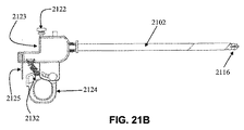
開創器カニューレデバイスの別の変形例は、図21Aおよび21Bに示される。開創器カニューレデバイス2100は、近位端2104および遠位端2106を有する管状体2102と、開創器アセンブリ2116と、ハンドル2118とを備えてもよい。開創器カニューレデバイス100と同様に、管状体2116の近位端2104は、ハンドル2118における1つ以上のポート、例えば、ハンドルポート2123および補助ポート2128に関連してもよい。ポートおよびハンドル2118は、種々のデバイスように構成されてもよく、例えば、デバイス連結具2122が、デバイス(例えば、内視鏡)をハンドル2118に取着することに有用となるように提供されてもよい。ハンドル2118は、開創器アセンブリ2116の構成を制御するように構成され得る、旋回レバー2124等、管状体2102の遠位端2106(例えば、開創器アセンブリ2116)のナビゲーションおよび作動のための作動装置を備えてもよい。図21Bに示されるように、バネ2132は、旋回レバー2124をある構成に偏向するように提供されてもよい。枢また、動レバー係止部2125が、旋回レバー2124の作動を制限するために、所望に応じて含まれてもよい。また、レバー、スライダ、ボタン等の他の作動装置が、必要に応じて、含まれてもよい。
Another variation of the retractor cannula device is shown in FIGS. 21A and 21B. The
上述の開創器カニューレデバイスの種々の構成要素は、任意の好適な材料から成ってもよい。例えば、管状体および/または開創器アセンブリは、ステンレス鋼または剛性プラスチック等の剛性材料から成ってもよい。可撓性領域124は、可撓性生体適合性ポリマーまたは軟性金属の任意の組み合わせから成ってもよい。いくつかの実施形態では、可撓性領域は、管状体内のワイヤまたは支柱によって、あるいは、例えば、管状体内に提供される、他の伸長部材を摺動させることによって、作動されてもよい。代替として、または加えて、管状体は、強力かつ可撓性であってもよく、弾性ポリマー内に埋入されたステンレス鋼金属編組等、材料の組み合わせから成ってもよい。弾性ポリマーの実施例は、Pebax、ポリウレタン、およびシリコーンであってもよい(しかしながら、それらに限定されない)。
The various components of the retractor cannula device described above may be made of any suitable material. For example, the tubular body and / or retractor assembly may be made of a rigid material such as stainless steel or rigid plastic. The
開創器アセンブリ、可撓性領域、管状体、ハンドル等、開創器カニューレデバイスの種々の構成要素の寸法は、提供される特定の療法および標的身体領域に基づいて、寸法設定ならびに選択されてもよい。例えば、開創器カニューレデバイスの一実施形態は、診断評価および/またはそこに療法を適用するための脊椎領域へのナビゲーションに好適な寸法を有してもよい。別の実施形態では、開創器カニューレデバイスは、硬膜外腔内に嵌合するように、または椎間板に近接して、寸法設定されてもよい。他の実施形態は、胸腔(例えば、胸膜生検または胸水穿刺術)あるいは腹部−骨盤腔(例えば、膀胱頸部懸架)内における使用のため、もしくは、例えば、乳房生検および経膣卵母細胞の回収等の非脊椎手技のために構成されてもよい。いくつかの実施形態では、開創器カニューレデバイス100は、直径約5mm以下を有してもよい一方、他の実施形態では、開創器カニューレデバイスは、直径約3mm以下、またはさらに2.5mm以下を有してもよい。別の実施形態では、開創器カニューレデバイス100の作業チャネルのうちの1つ以上は、直径約5mm以下、約3mm以下、約2mm以下、約1mm以下、または約0.8mm以下を有してもよい。開創器カニューレデバイスの種々の構成要素の付加的詳細および説明は、後述される。
The dimensions of the various components of the retractor cannula device, such as the retractor assembly, flexible region, tubular body, handle, etc., may be sized and selected based on the particular therapy and target body area provided. . For example, one embodiment of a retractor cannula device may have dimensions suitable for diagnostic evaluation and / or navigation to the spinal region for applying therapy thereto. In another embodiment, the retractor cannula device may be dimensioned to fit within the epidural space or proximate to the intervertebral disc. Other embodiments are for use in the thoracic cavity (eg, pleural biopsy or pleural puncture) or in the abdominal-pelvic cavity (eg, bladder neck suspension), or for example, breast biopsy and transvaginal oocytes May be configured for non-spine procedures such as recovery of In some embodiments, the
(A.開創器アセンブリ)
開創器カニューレデバイス100は、異なる方法において、標的身体領域を操作するために使用されてもよい。例えば、開創器カニューレデバイスは、組織を拡張および/または変位させ、作業空間を創出する、標的組織を吸引および/または灌注する、薬物を注射する、物質を注入する、組織を除去する等のために使用されてもよい。さらに、開創器カニューレデバイスは、種々のデバイス、例えば、任意の可視化デバイス(例えば、内視鏡)、焼灼デバイス、拡張可能デバイス、熱エネルギーデバイス、刺激電極等を標的組織に送達するために使用されてもよい。異なる開創器アセンブリが、開創器カニューレデバイスと併用され、上述の機能のうちの1つ以上を有効にしてもよい。例えば、開創器アセンブリは、1つ以上の開創器要素、例えば、顎部を有してもよく、異なる機能、例えば、開放構成および閉鎖構成を果たすために、1つ以上の構成を有してもよい。開創器アセンブリを閉鎖から開放構成に遷移させることによって、開創器アセンブリの開創器要素は、周囲組織に対して外向きに付勢され、直接的可視化および/または付加的デバイスの挿入のための空間を提供してもよい。いくつかの変形例では、非外傷的開創器アセンブリは、閉鎖と開放構成との間を循環し、開創器カニューレデバイスの前進を補助してもよい。ある場合には、開創器アセンブリの動作は、内視鏡からの画像等、直接的可視化の補助とともに生じてもよい。非外傷的開創器アセンブリのいくつかの変形例は、開創器カニューレデバイスの管状体内の1つ以上のチャネルまたは内腔と連通する、作業チャネルを備えてもよい。縦方向内腔またはアクセス内腔、例えば、図13Aのチャネル1326、1328、および1330は、管状体の長さを通して延在してもよく、開創器アセンブリと連通していてもよい。これらのチャネルは、カテーテル、内視鏡、および器具/デバイス等の通過を可能にするように寸法設定されてもよい。
(A. retractor assembly)
The
開創器アセンブリの形状およびサイズは、組織環境(例えば、薄い組織対厚い組織、密集組織構造対低密集組織構造の領域、標的組織近傍の液体媒体の体積、標的組織の弾性等。)によって、可変であってもよい。いくつかの変形例では、開創器アセンブリの表面は、1つ以上の湾曲を有してもよく、開創器アセンブリ表面(例えば、閉鎖構成における)の曲率は、開創器カニューレデバイスの縦軸の周囲において均一であってもよく、または縦軸の周囲において、不均一であってもよい。例えば、開創器アセンブリの表面は、第1の角度または勾配を有する第1の表面に沿って先細であってもよく、第2の角度または勾配を有する第2の表面に沿って先細であってもよく、第1および第2の角度または勾配は、等しくなくてもよい。先細部は、1つ以上の角度または勾配を有してもよく、湾曲は、1つ以上の曲率半径を有してもよい。いくつかの変形例では、開創器アセンブリの表面は、第1の側により広幅の寸法を有し、第2の側により狭幅の寸法を有してもよい。ある形状および湾曲を有する、開創器アセンブリのある実施例が後述されるが、他の種類の開創器アセンブリが、開創器カニューレデバイスと併用されてもよく、所望の機能性ならびに標的身体領域または組織に従って可変であってもよく、例えば、異なるサイズ、異なる形状、異なる湾曲、および縦方向チャネルの数等を有することを理解されたい。 The shape and size of the retractor assembly is variable depending on the tissue environment (eg, thin vs. thick tissue, dense vs. less dense tissue structure, volume of liquid media near the target tissue, elasticity of the target tissue, etc.). It may be. In some variations, the surface of the retractor assembly may have one or more curvatures, and the curvature of the retractor assembly surface (eg, in a closed configuration) is around the longitudinal axis of the retractor cannula device May be uniform or non-uniform around the longitudinal axis. For example, the surface of the retractor assembly may be tapered along a first surface having a first angle or gradient and tapered along a second surface having a second angle or gradient. The first and second angles or gradients may not be equal. The taper may have one or more angles or slopes, and the curvature may have one or more radii of curvature. In some variations, the surface of the retractor assembly may have a wider dimension on the first side and a narrower dimension on the second side. Although certain examples of retractor assemblies having certain shapes and curvatures are described below, other types of retractor assemblies may be used in conjunction with the retractor cannula device to achieve the desired functionality and target body region or tissue. It should be understood that, for example, it may have different sizes, different shapes, different curvatures, number of longitudinal channels, etc.
(1.曲線状開創器アセンブリ)
開創器アセンブリの一実施形態は、図3Aから3Fに示される。開創器アセンブリ300の上方図は、図3Aに示され、開創器アセンブリ300の側面図は、図3Bに示され、斜視図は、図3Eに示される。ここに図示されるように、開創器アセンブリ300は、閉鎖構成にあるとき、顎部308および310が嵌合し、弾丸に類似する実質的に平滑な曲線形状を形成するように成形され、表面の曲率が、管状体102の中線399の周囲において均一である、2つの開創器要素である顎部308および310を備える。顎部308および310の表面は、遠位部分302において嵌合するように、対称に湾曲していてもよい。加えて、または代替として、開創器アセンブリの実施形態は、パドル、フラップ、ローブ、タブ、顎部等の1つ以上の開創器要素を備えてもよい。開創器アセンブリ300は、上述のように、球形、ドーム形、先細楕円形状、または周囲組織への外傷を低減させることに有用となり得る、任意の他の形状等、1つ以上の湾曲表面を伴って成形される顎部を有してもよい。曲線状開創器アセンブリは、図3Aおよび3Bに示され、顎部308および310は、それぞれ、図3Fに図示されるように、半球として成形される。図3Fは、内側縁309を有する顎部308の拡大図である(顎部310および内側縁311は、図示されるように、顎部308の鏡映である)。また、後述される、他の非外傷的幾何学形状が使用されてもよい。
(1. Curved retractor assembly)
One embodiment of the retractor assembly is shown in FIGS. 3A-3F. A top view of the
顎部308および310は、1つ以上の構成、例えば、閉鎖構成(図3Bの側面図および図3Eの斜視図に図示されるように)および開放構成(図3Cに図示されるように)を有してもよい。図3Bの顎部308および310は、閉鎖構成にあるとき、その外側縁の周囲において相互に接触するが、他の実施例では、顎部は、完全に閉鎖しなくてもよい。顎部308および310は、中線399の周りに対称的に開放および閉鎖するように示されるが、開創器アセンブリの他の変形例では、顎部は、開放と閉鎖構成との間を対称的に移動しなくてもよい。開放構成では、作業空間136は、2つの顎部308と310との間に提供されてもよい。開創器アセンブリ300は、顎部の遠位部分302が、閉鎖構成において、平滑な、曲線状の、および非外傷的形状を形成するように成形され得る3つ以上の顎部を含む、2つを超える顎部を備えてもよいことを理解されたい。顎部308および310は、蝶番機構306を使用して、管状体102に連結されてもよい。各顎部は、閉鎖構成と開放構成との間で遷移させられると、作業空間136を露出または提示するように、任意の好適な方法で構成される1つ以上の蝶番(306aおよび306b)によって、管状体102に連結されてもよい。いくつかの変形例では、顎部および任意の他の開創器要素は、ピン、マンドレル、ネジ等によって、管状体102に連結されてもよい。
The
ある実施形態では、蝶番機構306は、例えば、リベット、ピン、またはネジによって形成される、可動蝶番および/または機械的蝶番を備えてもよい。蝶番機構は、任意の好適な材料から成ってもよい。図3Bおよび3Cに示される一実施例では、蝶番機構306は、管状体102の外側表面に対して同一平面上にあり得る蝶番306aおよび306bを備える。蝶番306aおよび306bは、顎部308および310が、図3Cに示されるように、開放構成に遷移させられると、顎部308および310の1つ以上の遠位部分302が、他方から離れるように移動するか、またはデバイスの中線399から離れるように移動する、すなわち、相互に対称的に離れるように移動し、作業空間136を露出し得るように構成されてもよい。上述のように、顎部308および310は、相互に対称的に離れるように移動する、すなわち、中線399に平行な縦軸から相互に離れるように移動してもよい。一実施形態では、図3Cに例示されるように、顎部308および310の内側縁309および311は、角度を成し、開放構成では、この角度は、約90度であってもよい。他の実施形態では、内側縁309と内側縁311とによって形成される角度は、約60度、約90度、約120度、約180度、または270度を含む、約1〜約359度の任意の値であってもよい。開創器カニューレデバイスの蝶番機構306は、金属、またはプラスチック、あるいは他の類似好適な材料から成ってもよい。その上を蝶番306aおよび306bが回転するリベットを備える機械的蝶番に加え、いくつかの実施形態は、可動蝶番を利用してもよい。可動蝶番は、薄く可撓性の細片に形作られることが可能であって、器具シャフトと同一または異なる材料を備え得る、任意の材料を備えてもよく、金属、プラスチック、または他のポリマーであってもよい。いくつかの実施形態では、玉継手を含む、他の関節構造が使用されてもよい。ある実施形態では、管状体102と顎部308および310との間の関節構造は、付加的操縦性のために、管状体102に沿って、摺動可能であるように構成されてもよい。加えて、または代替として、開創器アセンブリ全体が、顎部角形成を有するか、または有することなく管状体に沿って、摺動可能であるように構成されてもよい。例えば、開創器アセンブリの開創器要素は、可撓性領域を介して、管状体に連結されてもよい。
In certain embodiments, the
いくつかの変形例では、開創器アセンブリ300が開放構成にあるとき、顎部308および310は、開創器カニューレデバイスと併用され得る、任意の可視化器具の視野を改善することに有用となり得る作業空間を提供するように構成される。例えば、可視化デバイス(例えば、内視鏡)が、作業空間136に近接して、顎部308と310との間に提供される場合、開放構成における開創器アセンブリ300は、可視化を向上させ、それを変位させることに有用となり得る前方視能力を提供してもよい。この前方視能力は、内側縁309と311との間の角度を変更する、蝶番機構306の可撓性を調節する、および/または顎部308および310のサイズならびに形状を変更する、および他の関連要因によって、可視化および変位される組織に従って、調節されてもよい。
In some variations, when
いくつかの実施形態では、作業空間136は、管状体102と連通している。図3Bに示される線3D−3Dに沿った開創器アセンブリ300の断面を図示する、図3Dを参照すると、開創器カニューレデバイスのある実施形態は、開創器アセンブリを制御および/またはナビゲートし、顎部308および310を作動させる任意の構造を支持することに有用となり得る、管状体102の内腔312内に内側シャフト316を有してもよい。内側シャフト316は、縦軸(AL)に沿って、軸方向に摺動可能であって、顎部308および310の運動を作動させてもよく、作業空間136と連通していてもよい。例えば、内腔312または内側シャフト316は、顎部作動機構の少なくとも一部を格納してもよい。顎部作動機構の一実施例は、図3Dに図示される。ここに示されるように、内側シャフト316は、ピン314によって関節運動し得るタブ315を備え、ピン314は、顎部308および310に連結されてもよい。内側シャフト316の摺動は、顎部308および310が、外向きに旋回し得る(すなわち、他方から離れるように移動し得るか、またはデバイスの縦軸(AL)から離れるように移動し得る)ように、タブ314を平行移動させ、ピン314を回転させてもよい。内側シャフト316は、ハンドル118上の作動装置、例えば、スライダ119を使用して、制御されてもよい。他の実施形態は、顎部を開放または閉鎖するために、他の作動機構、例えば、引張ワイヤまたは支柱を使用してもよい。引張ワイヤは、単鎖または多重鎖であり得る、金属またはポリマーワイヤを含んでもよく、ねじりまたは編組部材が含まれてもよい。さらに他の実施例では、顎部の移動は、非対称(例えば、一方の顎部が、ある位置に偏向される一方、他方の顎部は、非偏向である等)であってもよく、または1つ以上の顎部が、不動である一方で、1つ以上の他の顎部が可動であってもよい。
In some embodiments, the working
(2.先細形状の開創器アセンブリ)
開創器アセンブリ401の別の実施形態は、図4Aから4Fに図示される。開創器アセンブリ401は、2つの開創器要素である顎部408および410を備える。加えて、または代替として、開創器アセンブリの実施形態は、パドル、フラップ、ローブ、タブ、顎部等の1つ以上の開創器要素を備えてもよい。顎部408および410は、中線499の周囲において不均一である曲率を有する。図4Aおよび4Bに示されるように、顎部408は、縦軸、例えば、中線499に沿って、1つ以上の勾配または角度を伴って、先細である。図4Aの上方図に示されるように、開創器アセンブリ401は、顎部408の第1のプロファイル上に第1の曲率を有し、第1の曲率は、遠位部分402に向かって、概して平滑および曲線状である第1の先細部と、遠位部分402において曲線状である第2の先細部とを有する。図4Bは、顎部408が、遠位部分402に向かって先細となり得る、例えば、顎部408の先細部が、近位に平坦であって、遠位に急勾配であり得る場合を示す拡大図である。図4Cは、図4Aおよび4Bに示される図に垂直な開創器アセンブリ401の側面図を図示する。ここに示されるように、顎部408および410の表面曲率は、開創器アセンブリ401の上方図からみた場合の表面曲率と異なる、すなわち、顎部表面の曲率は、中線499の周囲において不均一である。側面図から、開創器アセンブリ401は、図4Aおよび4Bに示される第1のプロファイルと比較して、第2のプロファイルに沿って、より段階的または均一の先細を有する。これは、図4Eおよび4Fからも分かるであろう。顎部408および410は、少なくとも2つの異なる湾曲表面(例えば、上方図から分かる第1の先細表面、および上方図に垂直な側面図から分かる第2の先細表面)を有するが、他の実施形態では、断面または側方プロファイルは、上方プロファイルからの先細部より先細であるか、またはそれより先細でなくてもよく、顎部408および410の先細部は、近位に増加し、および/または遠位に減少してもよい。他の実施形態では、任意の先細または非先細構成が、使用されてもよい。顎部408および410は、2つの直交する顎部表面上に対称な先細部を有してもよいが、他の顎部変形例は、2つを超える顎部表面(直交または直交していなくてもよい)上に対称な先細部を有してもよく、および/または、標的組織環境を通して、非外傷的にナビゲートするために好適な非対称な先細部を有してもよい。本特定の実施例では、顎部408および410は、鋭角を有する断面プロファイル(図4F参照)を有し、頂部は、図4Cに示されるように、閉鎖構成において、平坦な先細先端404を形成する。
(2. Tapered retractor assembly)
Another embodiment of the
開創器アセンブリ300に関して記載のように、開創器アセンブリ401は、同一または類似構成を有してもよい。開放構成は、図4Dの実線に例示されており、顎部408および410の作用を示す一方、点線は、閉鎖構成における顎部408および410の位置を表す。顎部は、矢印405および403の方向に蝶番406を回転させることによって、開放構成に付勢されてもよく、縁409と411との間に角度が創出され、顎部は開放構成をとる。開放構成では、縁409と411との間の角度は、最大約30度、約60度、約90度、約120度、約180度、約270度以上を含む、約0度〜約270度以上の任意の値であってもよい。上述のように、いくつかの実施形態では、両方の顎部408および410が、対称的に開放または閉鎖する必要はなく、いくつかの実施形態では、一方または両方の顎部は、管状部材102に対して、固定位置を有してもよい。開創器アセンブリ401の作動機構は、上述および図3Dに図示される開創器アセンブリのために開示される作動機構と同一または異なってもよい。蝶番機構、構成、機能、およびその作動については、上述、例えば、図3Dに記載および図示されている。
As described with respect to the
(3.角度付き開創器アセンブリ)
開創器アセンブリのある実施形態では、顎部は、形状または移動において、デバイスの中線を中心として対称でなくてもよい。図22A−22Cは、開放構成における角度付き開創器アセンブリ2200を図示しており、角度付き開創器アセンブリ2200は、角度2203を有する第1の顎部2208と、角度を有さない第2の顎部2210とを備える。いくつかの実施形態では、第2の顎部2210は、任意であってもよい。第1の顎部2208は、曲線状先端2204を備えてもよく、曲線状先端2204の形状は、曲線状先端空洞2212が、その中に提供されるようなものである。角度2203は、1度〜180度、例えば、約150度〜約179度、または約100度〜約130度、または約120度〜約160度、または約90度〜約120度の任意の角度を有してもよい。上述のように、角度付き開創器アセンブリ2200は、ここでは、その開放構成において示されている。その閉鎖構成に作動させられると、第1の顎部2208の少なくとも一部、例えば、曲線状先端2204は、中線2207を越えて延在してもよい。これは、開創器アセンブリ2200が、曲線状先端2204において、組織を把持および/または係着することに有用となり得る。組織が係合される程度は、後述されるように、他の特徴とともに、角度2203を変更することによって調節されてもよい。いくつかの変形例では、中線2207を越えた第1の顎部2208の延在は、開創器アセンブリ2200に収まらず、閉鎖構成においてさえ、管状体2202の1つ以上の内腔内の流体またはデバイスが、依然として、開創器アセンブリ2200から出る状態であってもよい。例えば、閉鎖構成では、第1の顎部2208および第2の顎部2210は、側部開口を形成してもよく、単一顎部を有する変形例では、顎部2209は、管状体2202とともに側部開口を形成してもよい。第1の顎部2208の形状は、第1の顎部空洞2209が、その中に含有されるようなものであって、図22Bに図示されるように、第1の顎部空洞2209および曲線状先端空洞2212は、相互に連通していてもよい。また、曲線状先端2204は、図22Cから分かるように、洗浄溶液または造影剤を注入するために使用され得る曲線状先端孔2214を有してもよい。作業空間2230は、概して、第1の顎部2208と第2の顎部2210との間の領域として画定されてもよく、曲線状先端空洞2212および第1の顎部空洞2209、ならびに組織を拡張させることに伴って、開創器アセンブリ2200によって創出される、任意の付加的空間を含んでもよい。
(3. Angled retractor assembly)
In certain embodiments of the retractor assembly, the jaws may not be symmetrical about the midline of the device in shape or movement. 22A-22C illustrate an
他の開創器アセンブリ実施形態と同様に、第1の顎部2208は、図22Cに図示されるように、側部の蝶番2206ならびに上部の二次的蝶番2205によって、管状体2202に取着されてもよい。いくつかの変形例では、蝶番2206は、機械的蝶番、例えば、ピン、ネジ、回転可能部材等であってもよく、二次的蝶番2205は、屈曲し得るが、回転しない、可動蝶番であってもよい。一般に、所望に応じて、開創器アセンブリ2200を開放、閉鎖、および屈曲させる、任意の好適な蝶番機構が、使用されてもよい。第2の顎部2210は、図22A−22Cに示されるように、管状体2202に固定連結されて示されるが、他の実施形態では、また、蝶番機構によって、管状体2202に連結されてもよい。第2の顎部2210は、第1の顎部2208より長さが大幅に短くてもよいが、他の変形例では、相互に対する顎部のそれぞれのサイズは、組織の把持、拡張、および操作の所望のレベルに従って、可変であってもよい。いくつかの実施形態では、第1の顎部2208および第2の顎部2210は、閉鎖構成でさえ、その中に含有される可視化デバイス(例えば、内視鏡)が、依然として、画像を取得可能であり得るように、クリア材料、すなわち、光学的に透明から成ってもよい。第1の顎部2208および第2の顎部2210は、後述のように、付加的特徴を備え、付加的または異なる構成を有してもよい。
Similar to other retractor assembly embodiments, the
開創器アセンブリの他の実施形態では、開創器アセンブリは、延出可能構造であってもよく、延出可能構造は、1つ以上の支持要素を具備してもよい。支持要素は、開創器アセンブリ顎部に沿って、縦方向、半径方向、および/または円周方向に配向され、顎部がとり得る種々の構成を支持してもよい。支持要素の構成は、開創器アセンブリの形状または構成に相補的であってもよい。一実施形態では、支持要素は、例えば、螺旋構成を備えてもよい。いくつかの実施形態では、支持要素は、管状体内腔(例えば、内腔312)を中心として設置されてもよい。支持要素は、金属および/またはポリマー材料を含むが、それらに限定されない、種々の材料のいずれかを備えてもよい。支持要素は、剛性、半剛性、または可撓性であってもよく、支持要素の少なくとも一部は、シャフト、開創器アセンブリの内側あるいは外側表面に取着もしくは連結され、および/または開創器アセンブリの内側縁内に埋入されてもよい。 In other embodiments of the retractor assembly, the retractor assembly may be an extendable structure, and the extendable structure may comprise one or more support elements. The support elements may be oriented longitudinally, radially, and / or circumferentially along the retractor assembly jaws to support various configurations that the jaws can take. The configuration of the support element may be complementary to the shape or configuration of the retractor assembly. In one embodiment, the support element may comprise a helical configuration, for example. In some embodiments, the support element may be placed about a tubular body lumen (eg, lumen 312). The support element may comprise any of a variety of materials, including but not limited to metallic and / or polymeric materials. The support element may be rigid, semi-rigid, or flexible, and at least a portion of the support element is attached or coupled to the shaft, the inner or outer surface of the retractor assembly, and / or the retractor assembly It may be embedded in the inner edge of.
(4.開創器アセンブリ構成および機構)
上述のように、開創器アセンブリは、組織の非外傷的操作およびそれを通してのナビゲーションのために、必要に応じて任意のサイズまたは幾何学形状をとり得る、1つ以上の開創器要素、例えば、顎部を有してもよい。開創器アセンブリを作動させるための機構の実施例が、上述されているが、他の機構が、種々の機能のための種々の構成において、開創器アセンブリを配置するために使用されてもよい。ある実施形態では、開創器アセンブリを作動させる機構は、一方の構成、または他方、あるいは第3の構成に向かって偏向されてもよい。例えば、顎部または開創器要素は、作動力の不在の下において、開創器アセンブリが閉鎖構成のままで作動させられると、開放構成をとるように閉鎖構成に向かって偏向されてもよい。閉鎖構成に向かう偏向を有する開創器アセンブリは、例えば、除去または置換のために、組織を操作および/または把持するために使用されてもよい。他の実施形態では、開創器部材は、作動力の不在の下において、開創器アセンブリが、開放構成のままであって、作動させられると、閉鎖構成をとるように開放構成に向かって偏向されてもよい。開放構成に向かう偏向を有する開創器アセンブリは、例えば、拡張器として使用されるか、あるいは組織または構造を変位させてもよい。種々の偏向機構が、当技術分野において一般的であるように、利用されてもよく、例えば、バネが、開創器部材を特定の構成に維持するために使用されてもよい(例えば、図21Bに示される偏向バネ2132)が、力は、バネ力を克服し、開創器部材を代替構成に遷移させるように印加されてもよい。バネまたは他の偏向部材は、1つ以上の顎部部材に直接作用してもよく、またはデバイスの近位筐体内に位置する作動装置に作用してもよい。当然ながら、ある実施形態は、構成に対する偏向を欠いていてもよい。いくつかの実施形態では、開創器アセンブリは、1つ以上の構成に解放可能に係止可能であってもよい。例えば、顎部は、その内側縁間に、約60、約90、約120、約180、または約270度を含むが、それらに限定されない、約0〜約180度以上の種々の角度付き位置に係止可能であってもよい。各開創器部材の移動範囲は、同一または異なってもよい。開創器アセンブリのある実施例では、1つ以上の開創器要素は、固定位置を有してもよい一方、1つ以上の他の開創器要素は、可動であってもよい。例えば、図4Dを参照すると、両方の顎部408および410が、可動または旋回可能であって、内側縁の間に角度を創出するが、しかしながら、他の実施形態では、顎部のいずれかは、固定位置を有してもよい一方、他の顎部は、可動であることを理解されたい。図22Aを参照すると、顎部2210は、所与の場所に固定されてもよく、顎部2208は、蝶番2206を中心として旋回し、所望の構成を得てもよい。
(4. retractor assembly configuration and mechanism)
As described above, the retractor assembly may include one or more retractor elements, such as one or more retractor elements, that may take any size or geometry as needed for atraumatic manipulation of tissue and navigation therethrough. You may have a jaw part. Although examples of mechanisms for operating the retractor assembly are described above, other mechanisms may be used to position the retractor assembly in various configurations for various functions. In certain embodiments, the mechanism for actuating the retractor assembly may be deflected toward one configuration, or the other, or a third configuration. For example, the jaw or retractor element may be deflected toward the closed configuration to assume an open configuration when the retractor assembly is operated in the closed configuration in the absence of an actuation force. A retractor assembly having a deflection toward a closed configuration may be used to manipulate and / or grasp tissue, for example, for removal or replacement. In other embodiments, the retractor member is deflected toward the open configuration to assume a closed configuration when the retractor assembly remains in the open configuration and is actuated in the absence of an actuation force. May be. A retractor assembly having a deflection toward the open configuration may be used, for example, as a dilator or may displace tissue or structure. Various deflection mechanisms may be utilized as is common in the art, for example, a spring may be used to maintain the retractor member in a particular configuration (eg, FIG. 21B). Can be applied to overcome the spring force and transition the retractor member to an alternative configuration. The spring or other deflecting member may act directly on one or more jaw members or may act on an actuator located within the proximal housing of the device. Of course, certain embodiments may lack a bias to the configuration. In some embodiments, the retractor assembly may be releasably lockable in one or more configurations. For example, the jaw may have various angled positions between its inner edges, including but not limited to about 60, about 90, about 120, about 180, or about 270 degrees, from about 0 to about 180 degrees or more. May be lockable. The range of movement of each retractor member may be the same or different. In certain embodiments of the retractor assembly, one or more retractor elements may have a fixed position, while one or more other retractor elements may be movable. For example, referring to FIG. 4D, both
開創器アセンブリによって提供される作業空間は、開創器要素、例えば、顎部の幾何学形状および構成に関して特性化されてもよい。ある実施形態では、作業空間は、異なる開創器要素の任意の2つの領域間の総空間として、直接的に特性化されてもよい。作業空間は、開創器要素の特定の構成に応じて、可変であってもよい。いくつかの実施形態では、開創器アセンブリは、その移動範囲内において、開創器アセンブリによって達成可能な最大作業空間によって特性化されてもよく、最大作業空間は、組織の可視化および変位を向上させることに有用となり得る、前方視能力を提供してもよい。器具の実際の作業空間および/または最大作業空間は、周囲組織または構造によって制限または限定され得る。当業者は、作業空間または最大作業空間が、開創器アセンブリによって提供される最大視認能力と相関し得ても、またはそうでなくてもよいことを理解するであろう。例えば、顎部が約180度離れている作業空間は、狭小であり得るが、顎部の位置は、最大作業空間を提供する顎部角度よりも内視鏡先端から離れた大量の組織を実質的に変位させ得る。したがって、いくつかの事例では、有効視認空間は、カニューレデバイスの遠位端を囲繞する変位および非変位組織別に境界されてもよい。いくつかの実施形態では、作業空間は、開創器アセンブリの幾何学形状に伴って可変であってもよく、例えば、伸長および/または先細あるいは曲線状顎部構成を有する開創器アセンブリは、より短い顎部構成を有する開創器アセンブリよりも多くの組織を拡張させ得ることを理解されたい。いくつかの実施形態では、顎部の内側縁は、開創器アセンブリによる組織の偶発的な裂開の危険性を低減させることに有用となり得る平滑曲線状表面を備えてもよい。開創器要素のある実施形態では、開創器要素の内側縁は、種々の組織係合部材とともに構成されてもよい。組織係合部材は、例えば、椎間板の修復の際に、または組織生検用に、標的組織の一部を解離および/または除去するために有用であってもよい。他の実施形態では、顎部の内側縁は、組織係合部材を有してもよく、組織係合部材は、平滑でなくてもよく、例えば、組織係合部材は、フック、鉤爪、把持装置、歯等であってもよい。開創器アセンブリ、例えば、開創器アセンブリ300または401と併用され得る、組織係合部材の一実施例は、図5Aおよび5Bに示される。ここに図示されるように、開創器アセンブリ顎部500の内側縁502は、組織係合歯504を具備してもよい。内側縁502内の歯504の場所および配向は、偶発的な組織裂開の危険性を低減させることに有用であり得る一方、組織の変位および/または拡張のために、顎部500を作動させる。顎部500は、歯504を使用して、組織(例えば、除去、解離、生検等のため)に係合するために使用されてもよい。歯504の使用は、上述のように、ハンドル118の1つ以上のボタン、摺動作動装置、ダイヤル、レバー等によって、制御されてもよい。組織係合部材の一実施例が、図5Aおよび5Bに例示されるが、他の実施例では、組織係合部材は、標的組織に係合するために、必要に応じて、異なる幾何学形状および配列を有してもよい。ある実施形態では、図5Aおよび5Bに示されるように、歯504は、図5Aに示されるように、鋭利/鈍頭頂点を伴って、角度付きであってもよいが、任意の好適な幾何学形状、例えば、ドーム形、台形、螺旋等であってもよい。また、歯504は、内側縁502に対して、斜面に均一に設定され、初期接触後、組織を最適に固定し得るが、組織係合部材は、交互に適合するように設定されてもよく、例えば、組織係合部材は、異なる斜面を有するか、または斜面を有さずに、不均一に設定されてもよく、組織係合部材は、不均一形状であってもよいことを理解されたい。歯504が、内側縁502を越えて延在する程度は、可変であってもよく、一部は、図5Aに示されるように、縁502を越えて延在するが、他の実施形態では、組織係合部材は、縁502を越えて、突出または延在しなくてもよい。開創器要素の内側縁上の組織係合部材は、縁から好適な距離だけ離れて設定され、標的身体領域に向かって開創器カニューレデバイスのナビゲーションの際、周囲組織への外傷を制限してもよい。いくつかの実施形態では、内側縁上の組織係合部材は、顎部500の内側縁502から約0.1mm〜約1mm以上離れて設定される。いくつかの実施形態では、組織係合部材、例えば、歯504は、顎部408の底面図を示す、図5Bに図示されるように、内側縁502の周縁に沿って配列されてもよい。ここに示されるように、歯504は、顎部の内側空洞の一部を敷設するように配列されてもよい。組織係合部材の任意の配列および任意の密度(内側縁502全体において均一であっても、またはそうでなくてもよい)が、内側縁において使用されてもよいことを理解されたい。歯504は、顎部500と同一材料から成ってもよいが、また、異なる材料から成ってもよい。加えて、または代替として、親水性または疎水性材料等、他の表面強化物およびコーティングが、開創器要素および/または突起の内側縁に適用されてもよい。
The workspace provided by the retractor assembly may be characterized with respect to the retractor elements, eg, jaw geometry and configuration. In certain embodiments, the work space may be directly characterized as the total space between any two regions of different retractor elements. The work space may be variable depending on the particular configuration of the retractor element. In some embodiments, the retractor assembly may be characterized by a maximum working space achievable by the retractor assembly within its range of movement, the maximum working space improving tissue visualization and displacement. It may provide forward vision capabilities that may be useful. The actual working space and / or maximum working space of the instrument may be limited or limited by the surrounding tissue or structure. One skilled in the art will appreciate that the working space or maximum working space may or may not correlate with the maximum viewing capability provided by the retractor assembly. For example, a workspace where the jaws are about 180 degrees apart may be narrow, but the location of the jaws will allow a substantial amount of tissue farther from the endoscope tip than the jaw angle providing the maximum workspace. Can be displaced. Thus, in some cases, the effective viewing space may be bounded by displaced and undisplaced tissue surrounding the distal end of the cannula device. In some embodiments, the working space may vary with the geometry of the retractor assembly, e.g., a retractor assembly having an elongated and / or tapered or curved jaw configuration is shorter It should be understood that more tissue can be expanded than a retractor assembly having a jaw configuration. In some embodiments, the inner edge of the jaw may comprise a smooth curved surface that may be useful in reducing the risk of accidental tissue tearing by the retractor assembly. In certain embodiments of the retractor element, the inner edge of the retractor element may be configured with various tissue engaging members. The tissue engaging member may be useful for dissociating and / or removing a portion of the target tissue, for example, during disc repair or for tissue biopsy. In other embodiments, the inner edge of the jaw may have a tissue engaging member, and the tissue engaging member may not be smooth, for example, the tissue engaging member may be a hook, a claw, a grip It may be a device, a tooth or the like. One example of a tissue engaging member that may be used in conjunction with a retractor assembly, eg,
いくつかの実施形態では、その内側縁に提供される開創器要素および任意の組織係合部材は、ポリエステルコポリマー(PETG、PETE)、ナイロン、ウレタン、ポリカーボネート、アクリル、および/またはシリコーン等(しかしながら、それらに限定されない)の任意の透明ポリマーから成ってもよい。いくつかの実施形態では、開創器要素は、不透明材料から成ってもよい。代替として、または加えて、開創器要素は、次いで、上述のポリマーのうちの1つ以上によって被覆され得る、金属フレームを有してもよい。フレームは、ステンレス鋼、チタン合金、コバルトクロミウム、タングステン、タンタルから成ってもよい(しかしながら、それらに限定されない)。ある実施形態では、開創器要素の少なくとも一部は、ガラスから成ってもよい。代替として、または加えて、開創器要素は、X線撮像において、管状体102の遠位先端の可視化を可能にするX線不透過材料から構築されてもよい。他の実施形態では、開創器要素は、外部撮像モダリティを使用して知覚可能な開創器要素の全部または一部を成す、マーカまたは他の特徴を含む。別の実施形態では、マーカまたは特徴は、X線不透過マーカである。代替として、または加えて、開創器要素は、超音波または他の撮像モダリティによって、容易に解像される材料から構築されてもよい。いくつかの実施形態では、顎部の一部(例えば、遠位/前方視部分)は、軟材料から成り、周囲組織への外傷を最小にしてもよい。
In some embodiments, the retractor element and any tissue engaging member provided on its inner edge is a polyester copolymer (PETG, PETE), nylon, urethane, polycarbonate, acrylic, and / or silicone, etc. (however, (But not limited to) any transparent polymer. In some embodiments, the retractor element may be made of an opaque material. Alternatively or in addition, the retractor element may then have a metal frame that may be covered by one or more of the polymers described above. The frame may be made of (but not limited to) stainless steel, titanium alloy, cobalt chromium, tungsten, tantalum. In certain embodiments, at least a portion of the retractor element may be made of glass. Alternatively or additionally, the retractor element may be constructed from a radiopaque material that allows visualization of the distal tip of the
図3Eおよび4Eに示されるように、開創器要素、例えば、顎部の遠位部分は、可視化デバイス等、ポート構成要素の動作のために望ましくあり得る、透明な材料から選択されてもよい。いくつかの実施形態では、開創器アセンブリは、剛性クリアプラスチックから形成されてもよい一方、他の実施形態では、開創器アセンブリは、可撓性変形可能材料を備えてもよい。いくつかの実施形態では、開創器アセンブリは、不透明材料を備えるが、他の実施形態では、開創器アセンブリに隣接する組織または構造の可視化を促進し得る、半透明または透明であってもよい。開創器アセンブリ材料の遠位部分は、例えば、ステンレス鋼、コバルトクロミウム、チタン、ニッケルチタン、ポリカーボネート、アクリル、ナイロン、PEEK、PEK、PEKK、PEKEK、PEI、PES、FEP、PTFE、ポリウレタン、ポリエステル、ポリエチレン、ポリオレフィン、ポリプロピレン、ガラス、ダイヤモンド、石英、またはそれらの組み合わせであってもよい。いくつかの実施形態では、開創器アセンブリ材料は、1つ以上のX線マーカまたは材料の添加を含んでもよい。 As shown in FIGS. 3E and 4E, the retractor element, eg, the distal portion of the jaw, may be selected from a transparent material that may be desirable for operation of the port component, such as a visualization device. In some embodiments, the retractor assembly may be formed from a rigid clear plastic, while in other embodiments, the retractor assembly may comprise a flexible deformable material. In some embodiments, the retractor assembly comprises an opaque material, but in other embodiments it may be translucent or transparent that may facilitate visualization of the tissue or structure adjacent to the retractor assembly. The distal part of the retractor assembly material is, for example, stainless steel, cobalt chromium, titanium, nickel titanium, polycarbonate, acrylic, nylon, PEEK, PEK, PEKK, PEKEK, PEI, PES, FEP, PTFE, polyurethane, polyester, polyethylene , Polyolefin, polypropylene, glass, diamond, quartz, or combinations thereof. In some embodiments, the retractor assembly material may include the addition of one or more x-ray markers or materials.
開創器アセンブリ300および401は、概して、管状体102の縦軸を中心として対称であってもいが、他の実施形態では、開創器アセンブリは、開創器アセンブリ2200等、非対称であってもよい。また、他の開創器アセンブリ顎部構成が使用されてもよく、細隙または窓が、随意に、直接的可視化を増加させるように提供されてもよい。例えば、開創器アセンブリ構成は、異なる顎部形状、可変壁厚を使用して、および/または顎部材料の1つ以上の領域に沿って、湾曲あるいは襞を予形成することによって、改変されてもよい。ある実施形態では、開創器アセンブリは、標的部位への療法剤の潅注または投与を可能にするために、遠位先端近傍に、細隙等の小開口を有してもよい。したがって、開創器カニューレデバイスの最遠位部分における開創器アセンブリは、構造およびサイズが可変であってもよい。いくつかの変形例では、開創器アセンブリは、標的組織への偶発的外傷を低減させることに有用となるように、寸法設定および成形されてもよい。
The
上述のように、開創器アセンブリの顎部は、ハンドル、例えば、ハンドル118に提供される、レバー、摺動作動装置、ボタン等を使用して、作動されてもよい。開創器カニューレデバイスのいくつかの変形例では、開創器アセンブリは、誘導可能であってもよく、開創器カニューレデバイスは、誘導機構、例えば、誘導機構120を使用して操縦され、組織を通してナビゲートする、および/またはそれを操作してもよい。例えば、開創器アセンブリは、閉鎖構成において、組織の襞を通して、開創器カニューレデバイスの挿入を促進してもよく、開放され、組織の襞間に空間を創出してもよい。いくつかの変形例では、施術者は、直接的可視化下、開創器カニューレデバイスを前進させ、周囲組織を操作、拡張、および/または変位させ、組織領域内に作業空間を創出してもよい。開創器カニューレデバイスの開創器アセンブリが、閉鎖から開放構成に、その顎部を拡張することに伴って、作業空間または開口部が、周囲組織内に創出され、それによって、開創器カニューレデバイスの前進または非外傷的操縦性を向上させてもよい。その後、非外傷的開創器アセンブリは、配備または別様に使用され、管状体内の1つ以上の作業チャネルによって提供される、開創器カニューレデバイスまたは他の治療デバイスのために、周囲組織を変形させる、および/または空間を利用可能にしてもよい(例えば、周囲組織を変位または拡張させることによって)。これらの方法のうちの1つ以上は、周囲組織を操作するために、組み合わせて使用されてもよいことが想定される。また、開創器カニューレデバイスを利用するための種々の他の方法のいずれかが、また、想定され、そのいくつかの実施例は、後述される。
As described above, the jaws of the retractor assembly may be actuated using a handle, such as a lever, slide actuator, button, etc. provided on the
開創器カニューレデバイスの実施形態は、標的領域における器具の配置を容易にすることに有用となり得る直接的可視化の下において、組織を通してナビゲートし、それを操作し得る。いくつかの開創器カニューレデバイスでは、可視化チャネルは、任意の好適/適切な撮像デバイス、例えば、内視鏡を収容するために提供されてもよい。例えば、器具は、器具によって提供される撮像または生理学的情報等の情報を使用して、誘導されてもよい。画像は、光ファイバ線または束、あるいは器具の遠位端上に留置されるカメラ等のデータデバイス、あるいはセンサまたはセンサの組み合わせからのものであってもよい。一実施形態では、センサは、光を利用して、画像を生成する。別の実施形態では、センサは、血液または他の体液に透過する少なくとも1つの赤外線波長を選択することによって、脊椎領域内に存在する血液場を透視するように適合される。いくつかの実施形態では、脊椎場内に存在する血液に透過する少なくとも1つの赤外線波長は、約1ミクロン〜約15ミクロンの波長を有してもよい。別の実施形態では、脊椎場内に存在する血液に透過する少なくとも1つの赤外線波長は、約1.5ミクロン〜約6ミクロンの波長を有する。さらに別の実施形態では、脊椎場内に存在する血液に透過する少なくとも1つの赤外線波長は、約6ミクロン〜約15ミクロンの波長を有する。さらに別の実施形態では、脊椎場内に存在する血液に透過する少なくとも1つの赤外線波長は、約1.0ミクロン〜約1.5ミクロン、約1.5ミクロン〜約1.9ミクロン、約2.0ミクロン〜約2.4ミクロン、約3.7ミクロン〜約4.3ミクロン、または約4.6ミクロン〜約5.4ミクロンの波長を有する。さらに別の実施形態では、波長は、神経組織を周囲組織および/または低血管新生神経組織に区別する際に使用するために、選択あるいは適合される。さらに別の実施形態では、波長は、神経組織を筋肉と区別するために選択される。波長選択情報および特性化と、赤外線内視鏡に関連する他の詳細については、米国特許第6,178,346号、米国特許出願公開第2005/0014995号、および米国特許出願公開第2005/0020914号に見出され、それぞれ参照することによって、全体として本明細書に組み込まれる。 Embodiments of the retractor cannula device can navigate through and manipulate tissue under direct visualization that can be useful in facilitating placement of instruments in the target area. In some retractor cannula devices, a visualization channel may be provided to accommodate any suitable / suitable imaging device, eg, an endoscope. For example, the instrument may be guided using information such as imaging or physiological information provided by the instrument. The image may be from a fiber optic line or bundle, or a data device such as a camera placed on the distal end of the instrument, or a sensor or combination of sensors. In one embodiment, the sensor uses light to generate an image. In another embodiment, the sensor is adapted to see through the blood field present in the spinal region by selecting at least one infrared wavelength that is transparent to blood or other bodily fluids. In some embodiments, the at least one infrared wavelength that transmits blood present in the spinal field may have a wavelength of about 1 micron to about 15 microns. In another embodiment, the at least one infrared wavelength that transmits blood present in the spinal field has a wavelength of about 1.5 microns to about 6 microns. In yet another embodiment, the at least one infrared wavelength that transmits blood present in the spinal field has a wavelength of about 6 microns to about 15 microns. In yet another embodiment, the at least one infrared wavelength transmitted to blood present in the spinal field is about 1.0 microns to about 1.5 microns, about 1.5 microns to about 1.9 microns, about 2. It has a wavelength from 0 microns to about 2.4 microns, from about 3.7 microns to about 4.3 microns, or from about 4.6 microns to about 5.4 microns. In yet another embodiment, the wavelength is selected or adapted for use in distinguishing neural tissue into surrounding tissue and / or hypovascularized neural tissue. In yet another embodiment, the wavelength is selected to distinguish neural tissue from muscle. For wavelength selection information and characterization and other details related to infrared endoscopes, see US Patent No. 6,178,346, US Patent Application Publication No. 2005/0014995, and US Patent Application Publication No. 2005/0020914. And are hereby incorporated by reference in their entirety.
(5.誘導機構)
上述のように、開創器カニューレデバイスの1つ以上の実施形態は、図1に図示される誘導機構120等、種々の誘導構成のいずれかを具備してもよい。一実施形態では、開創器カニューレデバイスは、2つの軸を備えるデバイスを含み、1つ以上の軸において誘導可能である。いくつかの実施形態では、1つの軸は、回転軸であってもよい。別の実施形態では、開創器カニューレデバイスは、誘導不可能である。さらに別の代替実施形態では、開創器カニューレデバイスは、脊椎の領域または身体の他の領域の一部にアクセスするように適合される、形状に予め形成されてもよい。形状は、特定の身体部位にアクセスするために、種々の角度付きおよび/または湾曲区分のいずれかを含んでもよい。さらに別の実施形態では、開創器カニューレデバイスは、開創器カニューレが、脊椎空間内で最大約360°の誘導能力を有し得るように、トロカール内に位置する。誘導機構、例えば、誘導機構120は、開創器カニューレデバイス100上に1つ以上の可撓性本体または可撓性領域124を含んでもよい。可撓性本体は、筐体118上に位置するレバー122等の制御部を操作することによって屈曲させられてもよい。誘導機構および屈曲領域124の種々の実施例は、以下に詳述される。
(5. Guidance mechanism)
As described above, one or more embodiments of the retractor cannula device may comprise any of a variety of guiding configurations, such as the
(B.管状体)
(1.可撓性領域)
上述のように、開創器アセンブリは、管状体と連結されてもよく、管状体は、標的身体領域内の開創器アセンブリの配置を制御するために使用されてもよい。管状体は、組織構造が、その中に挿入される任意の器具またはデバイスの周囲で崩壊する傾向にある、例えば、椎間板、硬膜外作業領域等、身体の解剖学的密集領域内において、開創器カニューレデバイスを操縦可能にするある特徴を備えてもよい。上述のように、開創器アセンブリ、例えば、開創器アセンブリ300および401は、図1および2に示されるように、誘導機構120によって制御され得る管状体、例えば、管状体102に直接連結されてもよい。ここに図示されるように、管状体102は、可撓性領域124を備える。いくつかの実施形態では、開創器アセンブリは、別個の可撓性構成要素によって、管状体102に連結されてもよい。管状体の屈曲範囲は、特定の設計に応じて可変であってもよい。開創器カニューレデバイスは、管状シャフトの中立位置に対して、片側または両側の屈曲範囲を伴って構成されてもよい。屈曲範囲は、約0度〜約135度であってもよい一方、他の実施形態では、屈曲範囲は、約0度〜約90度、時として、約0度〜約45度、またある時には、約0度〜約15または約20度であってもよい。他方の側の屈曲範囲は、該当する場合、第1の側より小さいか、同等であるか、またはそれ以上であってもよい。いくつかの実施形態では、屈曲角度の増加によって、管状シャフト内の1つ以上のチャネルを閉塞し得る、管状シャフトの折目または伸縮を生じさせてもよい。
(B. Tubular body)
(1. Flexible region)
As described above, the retractor assembly may be coupled to a tubular body, which may be used to control the placement of the retractor assembly within the target body region. Tubular bodies tend to retract within the anatomical dense areas of the body, such as intervertebral discs, epidural work areas, etc., where tissue structures tend to collapse around any instrument or device inserted therein. Certain features may be provided that allow the instrument cannula device to be steered. As described above, the retractor assembly, eg,
いくつかの実施形態では、管状体の屈曲範囲を向上させるために、1つ以上の撓曲溝が、管状体上に提供されてもよい。図6は、複数の溝272を備える、管状体270の一実施形態を図示する。溝272は、概して、円周方向の配向を有してもよいが、代替として、螺旋配向または他の配向を有してもよい。溝272は、管状体270の縦方向長に沿って、均等または不均等に離間されてもよい。一実施例では、可撓性領域の両端を中心として位置する溝は、可撓性領域の中央を中心として位置する溝よりさらに離れて離間されてもよい。溝272は、類似構成または異種構成を有してもよい。また、図6に図示される溝272は、概して、一定幅を有するが、他の実施形態では、幅は、溝の長さに沿って可変であってもよい。溝272の溝端274間の空間は、可撓性領域を備える溝272の間で実質的に類似または異なってもよい。
In some embodiments, one or more flexure grooves may be provided on the tubular body to improve the bending range of the tubular body. FIG. 6 illustrates one embodiment of a
図6に記載されるように、溝端は、曲線状構成、あるいは、例えば、楕円端、四角形端、三角形端、または任意の他の多角形形状を含むが、それらに限定されない、任意の他の構成を備えてもよい。図7Aに図示される実施例等、いくつかの実施形態では、曲線状端276は、溝278の残りの幅より大きな横方向寸法を有してもよい。いくつかの実施形態では、曲線状端は、四角形または角度付き端と比較して、溝の縁に沿って、撓曲応力をより分散させ得る。また、図7Aの拡大曲線状端276等、溝より大きな端は、撓曲の際、溝縁間の圧縮または接触度を低減させ、また、溝端における亀裂の危険性を低減させ得る。図7Bは、撓曲時の図7Aの拡大曲線状溝端276を図示する。いくつかの実施形態では、溝端は、図8に図示されるように、T形状溝端280等、より複雑な構成を有してもよい。
As described in FIG. 6, the groove end may be a curved configuration, or any other, including but not limited to, an elliptical end, a square end, a triangular end, or any other polygonal shape. A configuration may be provided. In some embodiments, such as the example illustrated in FIG. 7A, the
いくつかの実施形態では、溝領域毎の溝の数は、約1溝〜約100溝以上、時として、約12溝〜約50溝、また時には、約24溝〜約48溝のいずれかであってもよい。いくつかの実施形態では、可撓性領域の長さは、約1インチ〜約20インチ、時として、約4インチ〜約10インチ、また時には、約5インチ〜約8インチの長さのいずれかであってもよい。いくつかの実施形態では、可撓性領域の外径は、約0.05インチ〜約0.3インチ、時として、約0.08インチ〜約0.15インチ、また時には、約0.1インチ〜約0.12インチであってもよい。可撓性領域の壁厚は、約0.001インチ〜約0.01インチ、時として、約0.002インチ〜約0.006インチ、また時には、約0.003インチ〜約0.004インチの範囲であってもよい。溝272は、約0.004インチ〜約0.02インチの範囲、時として、約0.005インチ〜約0.015インチ、また時には、約0.006インチ〜約0.008インチの範囲の平均溝幅を有してもよい。溝272間の空間は、約0.015インチ〜約0.1インチの範囲、時として、約0.020インチ〜約0.050インチ、また時には、約0.025インチ〜約0.04インチであってもよい。溝端間の空間は、約0.004インチ〜約0.05インチ、時として、約0.006インチ〜約0.02インチ、また時には、約0.004インチ〜約0.01インチの範囲であってもよい。溝端の最大横方向寸法は、約0.004インチ〜約0.008インチ、また時には、約0.004インチ〜約0.03インチ、また時には、約0.01インチ〜約0.04インチの範囲であってもよい。
In some embodiments, the number of grooves per groove region is from about 1 to about 100 or more, sometimes from about 12 to about 50, and sometimes from about 24 to about 48. There may be. In some embodiments, the length of the flexible region is any length from about 1 inch to about 20 inches, sometimes from about 4 inches to about 10 inches, and sometimes from about 5 inches to about 8 inches. It may be. In some embodiments, the outer diameter of the flexible region is about 0.05 inches to about 0.3 inches, sometimes about 0.08 inches to about 0.15 inches, and sometimes about 0.1 Inches to about 0.12 inches. The wall thickness of the flexible region is about 0.001 inch to about 0.01 inch, sometimes about 0.002 inch to about 0.006 inch, and sometimes about 0.003 inch to about 0.004 inch. It may be a range. Groove 272 may range from about 0.004 inches to about 0.02 inches, sometimes from about 0.005 inches to about 0.015 inches, and sometimes from about 0.006 inches to about 0.008 inches. It may have an average groove width. The space between the
開創器アセンブリおよび管状体の可撓性領域の誘導および操縦は、任意の好適な機構を使用して制御されてもよく、その一実施例は、図9および10A−10Cに示される。図9を参照すると、誘導機構120は、1つ以上の可撓性領域124において、管状体102の屈曲を生じさせるように構成される。ここに図示されるように、誘導機構120は、ポート管類および開創器カニューレデバイス100の筐体118の一部が除去された状態で図示されている。誘導機構は、レバー車軸190において、回転または旋回するように構成されるレバー122を備える。レバー122は、シャフト102の長さに沿って摺動可能に設置され、管状体102の遠位位置に取着される2つの制御部材192に取着される。1つ以上の支柱191が、制御部材192に対して提供されてもよい。いくつかの実施形態では、支柱191は、制御部材192の配向変化、制御部材192の平滑摺動、および/または開創器カニューレデバイスの他の構成要素の制御部材192の移動によって生じる切断または他の損傷からの保護を向上し得る。いくつかの実施形態では、制御部材192の端部は、1つ以上の保定チャネルまたは保持構造物内において、レバー122に固定されるが、他の実施形態では、制御部材は、レバーの保定チャネル内にループを留置することによってレバーに固定され得る制御部材ループを形成するように、近位に取着されてもよい。いくつかの実施形態では、1つ以上の制御部材192または制御ループは、レバー内に圧着、巻着、縫着、およびまたは埋入されてもよい。移動範囲および力は、レバー122に作用する1つ以上の偏向部材198によって増強されてもよい。偏向部材198は、図9に図示されるように、螺旋バネを備えてもよいが、また、板バネまたは任意の他の種類の偏向部材構成を備えてもよい。また、レバー122の移動範囲は、筐体118内に提供される、レバー開口部199のサイズおよび/または構成によって、影響を受け得る。いくつかの実施形態では、任意の係止機構が、1つ以上の位置にレバーを実質的に維持するために提供されてもよい。制御部材192は、ワイヤ、ネジ山、リボン、または他の伸長構造を備えてもよい。制御部材192の可撓性および/または剛性は、特定の誘導機構に応じて可変であってもよい。また、さらなる実施形態では、制御部材192の特性は、その長さに沿って可変であってもよい。2つ以上の制御部材を備える実施形態では、制御部材は、対称的に、例えば、同一の長さ、断面領域、または形状、あるいは管状シャフトの縦軸に対して対向する取着部位を有するように構成される必要はない。また、個々の制御部材は、その長さに沿って、同一の構成を有する必要はない。
The guidance and steering of the retractor assembly and the flexible region of the tubular body may be controlled using any suitable mechanism, one example of which is shown in FIGS. 9 and 10A-10C. Referring to FIG. 9, the
例えば、図9に図示される制御部材192の近位端は、ワイヤ状部材を備えるが、図10Aに例示される制御部材252の遠位端250は、リボン構造254を備える。いくつかの実施形態では、リボン構造の表面領域が大きいほど、開創器カニューレデバイスの可撓性領域256への損傷の危険性が低減され得る。図10Aに図示される特定の実施形態では、リボン構造254は、管状シャフトの可撓性領域256あるいは他の遠位もしくは可撓性領域と機械嵌めおよび/または締まり嵌めを形成するU形状構成を有する。可撓性領域256は、リボン構造254を受容するように構成される1つ以上の切り欠き260、陥凹、または開口部262を備えてもよい。図10Aでは、切り欠き260は、可撓性領域256の唇部264に沿って、リボン構造254の滑脱を抑止するように提供される一方、開口部262は、リボン端264の挿入を可能にし、リボン構造254および可撓性領域256の相互嵌合を増強するために提供される。図10Bは、リボン構造266が開口部262を通して挿入される、別の実施形態を例示する。本特定の実施形態では、また、リボン構造266は、リボン構造266を可撓性領域256にさらに固定させるためのループを形成するように、それ自体の上に戻して溶接またはハンダ付けされてもよい。他の実施形態では、図10Cに図示されるように、リボン構造268の先端269は、リボン構造および可撓性領域または管状シャフトの材料に応じて、可撓性領域256または管状シャフトに接合あるいはハンダ付けされてもよい。
For example, the proximal end of the
いくつかの実施形態では、屈曲している間、開創器カニューレデバイスの管状体内の1つ以上のチャネルを通して挿入されている1つ以上の構成要素は、異なる程度の相対変位を示し得る。相対変位の程度は、構成要素と開創器カニューレデバイスとの間に該当する場合、屈曲の程度、固定または連結部位、および/または開創器カニューレデバイスの中立位置からの変位の程度によって影響を受け得る。図11Aを参照すると、開創器カニューレデバイス1100の開創器アセンブリ1116は、可視化チャネル128内に位置する内視鏡282とともに、中立位置(例えば、直線であるが、他の実施形態では、角度付きまたは湾曲していてもよい)で示されている。内視鏡282の先端284は、可視化チャネル128の端部286に近接している。開創器カニューレデバイス1100が、図11Bに示されるように撓曲させられることに伴って、内視鏡282の先端284は、特に、内視鏡282が、近位位置(例えば、筐体付近)において、開創器カニューレデバイス100に連結される実施形態において、可視化チャネル128の端部286に対して、相対的な遠位変位を示し得る。開創器カニューレデバイス100が、反対方向に撓曲させられると、いくつかの事例では、内視鏡282は、近位への後退を示し得る。変位を補償するために、ユーザは、所望に応じて、内視鏡282の位置を手動で調節してもよい。
In some embodiments, one or more components that are inserted through one or more channels in the tubular body of the retractor cannula device while flexing may exhibit different degrees of relative displacement. The degree of relative displacement, where applicable between the component and the retractor cannula device, can be affected by the degree of bending, the anchoring or coupling site, and / or the degree of displacement from the neutral position of the retractor cannula device. . Referring to FIG. 11A, the
また、いくつかの実施形態では、誘導機構は、誘導機構の操作によっても、少なくともある程度の位置調節が提供され、その変位の程度が排除されないまでも、低減させ得るように、内視鏡調節機構に連結されてもよい。他の実施形態では、内視鏡は、撓曲の際に、内視鏡の近位部分が、遠位部分より大きい変位を示すように、管状体の遠位領域付近において開創器カニューレデバイスに連結されてもよい。さらに他の実施形態では、バネまたは他の種類の偏向部材は、撓曲の際に、内視鏡位置を維持するために、管状体の遠位端に位置する干渉構造(図示せず)に対して、内視鏡を遠位に偏向させてもよい。いくつかのさらなる実施形態では、干渉構造は、所望に応じて、その干渉位置を回転させるか、またはそこから外側に移動させ、内視鏡をより遠位に配置することを可能にしてもよい。 Also, in some embodiments, the guidance mechanism may be provided with an endoscope adjustment mechanism so that manipulation of the guidance mechanism can also provide at least some degree of position adjustment and reduce the degree of displacement until not eliminated. It may be connected to. In other embodiments, the endoscope may be retracted to the retractor cannula device near the distal region of the tubular body such that upon bending, the proximal portion of the endoscope exhibits a greater displacement than the distal portion. It may be connected. In still other embodiments, a spring or other type of deflecting member is provided on an interference structure (not shown) located at the distal end of the tubular body to maintain the endoscope position during bending. In contrast, the endoscope may be deflected distally. In some further embodiments, the interference structure may allow the position of the endoscope to be placed more distally, if desired, by rotating or moving the interference position outward. .
(2.内腔およびチャネル)
上述のように、1つ以上の内腔またはチャネルが、開創器カニューレデバイスの管状体内に提供されてもよい。内腔および/またはチャネルは、種々の機能、例えば、可視化、解離、拡張、変位、吸引、潅注、薬物の注入、椎間板等の組織の増強、椎間板髄核等の組織の減圧、焼灼、刺激、デバイスの移植、および任意の他の所望の機能のために、デバイスおよび療法剤の送達のために使用されてもよい。図12Aおよび12Bに図示される一実施形態、例えば、管状体102は、開創器要素を伴わずに、2つのチャネル、例えば、管状体102の遠位端106で開放する可視化チャネル128およびチャネル130を示すように図示されている。他の実施形態では、しかしながら、管状体は、図13A−13Cおよび14の実施例に示されるように、異なる数のチャネル、あるいは異なる位置、断面領域、または断面形状を有するチャネルを含有してもよい。図12Aおよび12Bを参照すると、可視化チャネル128は、内視鏡チャネルとして、撮像デバイスを送達するために使用されてもよい一方、チャネル130は、1つ以上の器具の挿入のための作業チャネルとして使用されてもい。また、管状体102の内腔の少なくとも一部を封入し、可視化チャネル128およびチャネル130の少なくとも一部を封入し得る、内腔132が示される。1つ以上のチャネルは、管状体102の長さに実質的に及ぶ、縦方向長さを有してもよいが、他のチャネルは、管状体102より短い長さを有してもよく、遠位端106の近位で終端してもよい。また、他のチャネルは、例えば、カニューレデバイスの屈曲または他の移動を制御するために使用されてもよい。1つ以上のチャネルは、PTFEおよび種々の生体適合性潤滑コーティング材料のいずれかを含む、チャネル内の器具の摺動を容易にするための層またはコーティングを備えてもよい。いくつかの実施形態では、シャフトは、剛性または半剛性材料を備えてもよいが、他の実施形態では、可撓性材料を備えてもよい。
(2. Lumens and channels)
As described above, one or more lumens or channels may be provided within the tubular body of the retractor cannula device. Lumens and / or channels can have various functions such as visualization, dissociation, dilation, displacement, aspiration, irrigation, drug injection, augmentation of tissues such as intervertebral discs, decompression of tissues such as intervertebral disc nucleus, cauterization, stimulation, It may be used for device and therapeutic agent delivery for device implantation and any other desired function. One embodiment illustrated in FIGS. 12A and 12B, for example, the
近位において、管状体102のチャネル128、130、および132のうちの1つ以上は、1つ以上のポート108、110、112、および114と連通していてもよい。図1に図示される実施形態では、例えば、開創器カニューレデバイス100の可視化チャネル128は、内視鏡とインターフェースをとり、内視鏡ポートとして作用するように構成され得るポート114と連通していてもよい。代替として、または加えて、チャネル130はまた、器具の挿入および送達のために構成され得る、ポート112と連通してもよく、チャネル132は、潅注または吸引ポートとなるように構成され得るポート108と連通していてもよい。いくつかの実施形態では、同時注入および吸引を可能にし得る、別個の潅注ポートおよび吸引ポートが提供されてもよい。同時注入および吸引は、単一チャネルを使用した交互注入および吸引と比較して、作業視野の清浄を促進し得る。
Proximally, one or more of the
いくつかの実施形態では、可視化チャネル128が提供されてもよく、そこでは、可視化チャネルは、開創器アセンブリ116の幾何学形状および/または移動の変化によって、増強されてもよい。例えば、いくつかの開創器アセンブリは、開創器要素または顎部が約90度超または約180度超の角度を形成可能となる蝶番機構を有してもよい。他の実施例では、開創器アセンブリは、その関節点に対して、異なる縦方向長さを有してもよい。例えば、いくつかの開創器アセンブリは、シャフトのその関節点から少なくとも約1mm、約2mm、約3mm、約4mm、約5mm、約6mm以上の長さを有する開創器要素を有してもよい。各開創器要素の縦方向長さは、同一であるかまたは異なっていてもよい。使用される開創器カニューレデバイスは、開創器カニューレデバイスが配備された身体の領域に応じて、選択されてもよい。大型空洞を有する領域では、曲線形状開創器アセンブリは、視野を悪化させることなく、周囲組織への外傷を低減させるために使用されてもよい。組織がより密集または折畳される領域では、閉鎖構成の先細部を襞内で操縦可能にし、開放構成への遷移に応じて組織を実質的に拡張させ、より大きな視野および作業空間を可能にするため、先細形状の開創器アセンブリが使用されてもよい。他の実施例では、異なる構成を有する複数の開創器カニューレデバイスが、同一標的部位において、使用されてもよい。
In some embodiments, a
図12Aおよび12Bを参照すると、可視化チャネル128は、照射、可視化、および/または撮像構成要素の挿入/除去のための通路として使用され、開創器カニューレデバイス100の遠位端106における直接的可視化能力を提供してもよい。いくつかの実施形態では、可視化チャネル128は、光源から光を伝達し、管状体102の遠位端106付近の生体構造を光学的に可視化するために使用される1つ以上の光ファイバ束を含むが、それらに限定されない、1つ以上の照射、可視化、分析、および/または撮像構成要素を格納するか、あるいはそれらとともに一体的に形成されてもよい。
With reference to FIGS. 12A and 12B,
デバイス100の可視化チャネル128または遠位端106は、画像を生成する、あるいは組織もしくは組織特性を識別するために使用される、センサを含んでもよい。一実施例では、センサは、画像を生成するために、診断超音波に類似する、音響エネルギーを利用する。別の実施例では、センサは、画像または他の種類の構造または生理学的情報を生成するために、電気特性を利用する。さらに別の実施例では、センサは、センサに隣接する組織の種類を区別する。隣接する構造または組織を区別するために、センサによって使用されるいくつかの特性は、センサまたはプローブに隣接する組織の抵抗、静電容量、インピーダンス、膜電圧、音響、および光学特性を含む。加えて、センサまたは画像は、例えば、神経組織、コラーゲン、あるいは繊維輪の一部を識別する異なる種類の組織を区別するために使用されてもよい。センサは、適切な場所をにおけるプローブの位置付けに有用な骨、筋肉、神経組織、脂肪等を区別可能な多モデルまたは多センサプローブであってもよいことを理解されたい。
The
図13Aから13Cは、開創器カニューレデバイスの種々の実施形態を例示するものであって、異なる管状体は、そこを通る内腔またはチャネルの異なる数、サイズ、および形状を有してもよい。図13Aでは、開創器カニューレデバイス1300は、可視化デバイス(内視鏡等であるが、それらに限定されない)を格納するように構成される非円形チャネル1328と、療法デバイスを提供するために、または吸引ポートとして使用され得る非円形作業チャネル1326と、開創器アセンブリ作動装置内腔1332と、潅注あるいは吸引のための付加的ポート1330とを有する管状体1302を備えてもよい。また、随意に、管状体1302は、その外側表面1364上に1つ以上の構造1362を備える。これらの構造1362は、陥凹または突出構成を備えてもよく、例えば、導入器あるいはガイド部材に対して整列を維持する、もしくは開創器カニューレデバイス1300の任意の操作による摩擦抵抗量を低減させるために使用されてもよい。図13Bに図示されるように、開創器カニューレデバイス1368の管状体1366は、非円形可視化または潅注ポート1370と、円形療法デバイスまたは吸引ポート1372と、円形開創器アセンブリ作動装置内腔1374と、より大きな寸法を有する付加的潅注または付加的吸引のための付加的円形ポート1376とを有してもよい。図13Bに図示されるように、円形ポート1372、1374、および1376は、同一直径を有する必要はない。図13Cでは、開創器カニューレデバイス1380の管状体1378は、可視化または潅注ポート1382と、注入ポートあるいは療法デバイスもしくは吸引ポート1384と、開創器アセンブリ作動装置内腔1386とを有し、いずれのポートまたは内腔も、円形断面形状を有していない。カニューレデバイス内の種々の内腔の機能は、好適に互換可能であることが想定される。
FIGS. 13A through 13C illustrate various embodiments of a retractor cannula device, where different tubular bodies may have different numbers, sizes, and shapes of lumens or channels therethrough. In FIG. 13A,
再び、図13Aを参照すると、開創器カニューレデバイスの管状体100は、可視化チャネル1328と、より大きな作業チャネル1326と、付加的潅注/吸引ポート1330とを含んでもよい。開創器カニューレデバイス1300のチャネルおよび/またはポートは、行われる種類の療法に好適な種々の療法デバイスを受容するように構成されてもよい。療法デバイスは、周囲組織にエネルギーを印加するように構成され、使用されてもよい。また、療法デバイスは、組織を切除、穿刺、除去するために使用される外科手術用器具であってもよい。さらに、療法デバイスは、任意の従来の内視鏡器具であってもよいことを理解されたい。療法デバイスは、超音波デバイス、モータ駆動デバイス、レーザ系デバイス、RFエネルギーデバイス、熱エネルギーデバイス、凍結療法系デバイス、または行われる脊椎療法に基づいて選択される他のデバイスを含んでもよい。また、例えば、療法デバイスは、切除器または吸引機等、組織を除去するように適合される、機械的デバイスであってもよい。他の実施例は、以下に詳述される。さらに、開創器カニューレデバイス1300は、脊椎領域内に薬剤を注入するために使用されてもよいことを理解されたい。作業チャネルのサイズ、数、および配列は、行われる手技の種類に応じて、異なる構成に対して、容易器に適合可能である。より多いまたはより少ない数の作業チャネルが提供されてもよく、作業チャネルは、同一サイズおよび形状を有する必要はない。加えて、作業チャネルはまた、補助機能を果たすように構成されてもよい。一実施例では、チャネルまたはポートは、非外傷的先端が、脊椎空間内に前進されることに伴って、組織解離を補助するための灌注を提供するために使用されてもよい。灌注作業チャネルは、潅注作業チャネルに存在する流体が、開創器カニューレデバイスの遠位部分に指向されるように、近位で、注射器または静脈注入システム等の流体源と連通し、遠位で、開創器カニューレデバイスの遠位端と連通していてもよい。別の実施例では、潅注作業チャネルまたは別の作業チャネルは、非外傷的先端を漱洗する、または開創器カニューレツールの他の部分を清潔に維持するために使用されてもよい。図13Aに図示される特定の実施形態では、作業チャネル1326および可視化チャネル1328は、非円形断面形状を伴って構成される。いくつかの実施形態では、非円形形状は、チャネルまたはポート内で円形断面形状を有する器具の留置を可能にする一方、依然として、チャネル126および可視化チャネル1328を通しての流体および材料のための流路を提供する。また、非円形シャフトチャネルおよびポートに沿った共有または偏心流路は、別様に、カニューレシャフトの未使用区画を利用してもよい。円形チャネルまたはポートのみを有するシャフトと異なり、流路は、カニューレシャフトの全体断面積を増加させる必要なく、提供され得る。また、非円形断面形状を有するチャネルまたはポートは、相補的な非円形断面形状を有する器具と併用されてもよい。例えば、相補的非円形断面形状は、チャネルまたはポート内の器具の回転量を制御あるいは制限するために使用されてもよい。
Referring again to FIG. 13A, the retractor cannula device
図14は、屈曲面内の両側撓曲のために構成されるカニューレデバイス322の一実施形態の管状体320の概略図である。いくつかの実施形態では、管状シャフト320の1つ以上のチャネルは、撓曲の際に、内視鏡または器具の変位の程度を低減させるように構成され、配置され得る。図15では、例えば、管状シャフト320は、可視化チャネル324と、作業チャネル326とを備え、それぞれ、チャネル324および326の中心328および330は、カニューレデバイス322の屈曲面334に垂直な平面332に沿って位置する。平面332は、例えば、誘導機構の2つの遠位取着の中点間に位置してもよい。平面332および屈曲面334の相対的位置は、誘導機構が撓曲領域に係着される特定の様式に応じて、可変であってもよい。他の実施形態では、中心328および330は、平面332上に位置する必要はないが、チャネル324および326内に挿入される光学または作業器具の中心位置は、平面332上に位置する。例えば、チャネルおよび/または内視鏡の重心が、平面332上に位置する必要はないが、チャネルは、内視鏡の光学中心が、平面332と実質的に整列するように構成されてもよい(例えば、内視鏡のレンズが、非対称的に位置する場合、または中心視角の場合)。円形チャネルを備える実施形態では、チャネルの中心は、円形の中心であってもよい。非円形チャネルを備える他の実施形態では、チャネルの中心は、チャネル内に挿入され得る、最大円形物体の中心と同軸であるように特性化されてもよい。
FIG. 14 is a schematic view of a
図15に示される実施形態は、単一の屈曲面を有するカニューレデバイスを対象とするが、他の実施形態では、カニューレデバイスは、2つ以上の屈曲面を伴って構成されてもよい。これらの後者の実施形態の場合、1つ以上のチャネルは、一方の屈曲面と整列させられるが、別の屈曲面とは整列させられなくてもよい。いくつかの実施形態では、中心チャネルは、2つ以上の屈曲面と整列させられるように提供されてもよい。 Although the embodiment shown in FIG. 15 is directed to a cannula device having a single bend surface, in other embodiments, the cannula device may be configured with more than one bend surface. For these latter embodiments, one or more channels are aligned with one bending surface, but may not be aligned with another bending surface. In some embodiments, the central channel may be provided to be aligned with more than one bending surface.
いくつかの実施形態では、トロカールは、蛍光透視または他の外部撮像モダリティを使用して、トロカールを治療領域に近接して留置するように導かれる。神経および他の組織の周囲にトロカール先端を蛍光透視によってナビゲートしようとする従来の手技と対照的に、トロカールは、敏感な構造および特徴から離れて、安全に配置されたままであり得る。一実施形態では、トロカール先端は、傷つきやすい神経組織から約1〜約2cm以上に留保される。別の実施形態では、療法部位までの最後の約1〜約2cmの進行は、開創器カニューレデバイス内の可視化機構によって提供される直接的可視化を使用して行われる。 In some embodiments, the trocar is guided using fluoroscopy or other external imaging modality to place the trocar in proximity to the treatment area. In contrast to conventional procedures that attempt to fluoroscopically navigate the trocar tip around nerves and other tissues, the trocar can remain safely positioned away from sensitive structures and features. In one embodiment, the trocar tip is retained about 1 to about 2 cm or more from vulnerable nerve tissue. In another embodiment, the last about 1 to about 2 cm advancement to the therapy site is performed using direct visualization provided by a visualization mechanism within the retractor cannula device.
いくつかの実施形態では、トロカールが、除去され、開創器カニューレデバイス100が、トロカールによって形成される経路内に挿入される。他の実施形態では、管状トロカールが使用されてもよい。最終トロカール位置から、開創器カニューレデバイス100は、搭載された可視化能力を使用して、トロカールのチャネルまたは内腔を通して療法または治療部位までの残りの距離に沿って通過させられてもよい。搭載された可視化能力は、必要に応じて、神経ならびに他の組織を識別する、非外傷的に変位させる、および/または操縦するために、単独で、あるいは開創器アセンブリ116または他の種類の非外傷的先端と組み合わせて、使用されてもよい。周囲組織ならびに構造を操作する、および/または1つ以上の療法あるいは治療部位までの残りの距離を横断するために、任意の誘導機構が、開創器カニューレデバイス100上に提供されてもよい。他の実施形態では、開創器カニューレデバイス100は、剛性または固定構成を有してもよく、随意に、所望の位置に到達するように、トロカールを操縦することによって、操作されてもよい。代替実施形態では、トロカールは、トロカール挿入の際に、開創器カニューレデバイスを格納し、したがって、トロカールの位置付けを誘導するために、開創器カニューレデバイス内の可視化機構の直接的可視化能力を利用してもよい。さらに別の実施形態では、トロカールは、トロカール挿入の際に使用するために、開創器カニューレデバイス内に提供される撮像デバイスまたは構成要素と別個の撮像システムを具備してもよい。さらに別の実施形態では、トロカールは、開創器カニューレデバイス100から撮像構成要素のみ格納するための内腔とともに構成されてもよい。所望のトロカール位置に到達後、トロカールが除去され、撮像構成要素が、トロカールから除去され、開創器カニューレデバイス100内に再挿入される。さらに別の代替実施形態では、両外部撮像は、単独で、または直接撮像と組み合わせて、トロカール遠位端に配置するために使用されてもよい。
In some embodiments, the trocar is removed and the
(C.ハンドル部分)
上述のように、開創器カニューレデバイスは、管状体および開創器アセンブリのナビゲーションならびに使用を制御するために、ハンドル、例えば、ハンドル118を具備してもよい。また、ハンドルは、種々の機能ポートと管状体の縦方向チャネルおよび/または内腔との間のインターフェースとしての役割を果たしてもよく、管状体のチャネルおよび内腔は、開創器アセンブリのチャネルおよび内腔と連通していてもよい。次に、図16を参照すると、管状体362の近位端360は、それぞれ、開創器カニューレデバイス1600の1つ以上のチャネルおよびコネクタ374、376、378、380、ならびに382に対応する、1つ以上の管区間364、366、368、370、372に連結されてもよい。図16に記載されるように、デバイス382の作業チャネルに接続される管区間370管区間368等の別の管区間と連通していてもよい。本特定の管区間370は、例えば、中央ポート378および管区間368を通してアクセスされるデバイス382の作業チャネル内に挿入される流体または材料を洗浄あるいは吸引するために使用されてもよい。管区間の特定の設計特徴は、特定の機能に応じて、可変であってもよい。特定の管区間に連結されるコネクタは、種々のコネクタまたは器具インターフェースのいずれかを備えてもよい。いくつかの実施形態では、例えば、1つ以上のコネクタは、ルアロック等の標準コネクタを備えてもよい一方、他の実施形態では、コネクタは、非標準コネクタであってもよい。特定のチャネルに応じて、いくつかの実施形態では、デバイスから流体の逆流を抑止するために、逆止弁、隔壁、または止血弁が提供されてもよい。その寸法および可撓性または剛性を含む、特定のチャネルの特性は、その特定の用途に応じてもよい。図17では、例えば、開創器カニューレデバイス1700は、5つのポート386、388、390、392、および394を備え、より長い可撓性ポート388および392は、注入または吸引のために使用されてもよい。そのようなポートは、注射器等の大型要素の取着を容易するために有益となり得る。ポート390等の剛性ポートは、そうでなければ損傷され得るか、または、より大きな摩擦抵抗を示し得る管を通過することが困難であるような、器具に対してに提供されてもよい。
(C. Handle part)
As described above, the retractor cannula device may include a handle, eg, handle 118, to control the navigation and use of the tubular body and retractor assembly. The handle may also serve as an interface between the various functional ports and the longitudinal channels and / or lumens of the tubular body, the channels and lumens of the tubular body being channels and interiors of the retractor assembly. It may communicate with the cavity. Referring now to FIG. 16, the
療法デバイスは、好適な伝達モードを使用して、外部源からエネルギー供給されてもよい。例えば、レーザエネルギーは、身体外部で発生され、次いで、適切な療法デバイスを介して送達のための光ファイバによって伝達されてもよい。代替として、療法デバイスは、療法部位において、エネルギー、例えば、療法デバイス内の熱抵抗要素に搬送される外部源から電流を発生または変換してもよい。エネルギーが療法デバイスに供給される場合、エネルギーの伝達は、ワイヤ、内腔、熱導体、または光ファイバ束等、任意のエネルギー伝達手段を通してであってもよい。加えて、療法デバイスは、電波、マイクロ波、赤外線光、可視光、および紫外線光を含むが、それらに限定されない電磁エネルギーを送達してもよい。電磁エネルギーは、インコヒーレントまたはレーザの形態であってもよい。レーザ形態のエネルギーは、平行化または焦点がぼやかされてもよい。また、椎間板に送達されるエネルギーは、電流、超音波、または加熱要素からの熱エネルギーであってもよい。さらに、本明細書に説明される開創器カニューレデバイスの実施形態はまた、硬膜外神経組織の瘢痕化を低減、減少、または最小にするための化合物、化合物、または他の薬剤を分注するために使用されてもよいことを理解されたい。 The therapy device may be energized from an external source using a suitable transmission mode. For example, laser energy may be generated outside the body and then transmitted by an optical fiber for delivery via a suitable therapy device. Alternatively, the therapy device may generate or convert current at the therapy site from energy, eg, an external source that is delivered to a thermal resistance element within the therapy device. When energy is supplied to the therapy device, energy transfer may be through any energy transfer means such as a wire, lumen, heat conductor, or fiber optic bundle. In addition, the therapy device may deliver electromagnetic energy, including but not limited to radio waves, microwaves, infrared light, visible light, and ultraviolet light. The electromagnetic energy may be in the form of incoherent or laser. The energy in the form of a laser may be collimated or blurred. Also, the energy delivered to the intervertebral disc may be current, ultrasound, or thermal energy from a heating element. In addition, embodiments of the retractor cannula device described herein also dispense compounds, compounds, or other agents to reduce, reduce, or minimize scarring of epidural nerve tissue It should be understood that it may be used for
図1に図示される実施形態に記載されるように、可視化チャネル128は、内視鏡撮像および/または医療撮像構成要素のために、標的領域へのアクセスを提供する。開放構成における開創器アセンブリの開創器要素は、拡張器または開創器として作用し、より広い視野を可能にしてもよい。例えば、開創器カニューレデバイスは、最初に、標的身体領域に向かって非外傷的にナビゲートするために、閉鎖構成をとってもよい。シャフトの遠位端が標的領域に到達すると、開創器アセンブリは、開放構成へと遷移し、周囲組織を拡張させ、可視化チャネル128内に配置された内視鏡を標的組織に視覚的にアクセス可能にする。いくつかの実施形態では、開創器アセンブリの開創器要素は、閉鎖構成においても、可視化チャネル128内に常住する内視鏡が、周囲組織への視覚的アクセスを有し、内視鏡が、カニューレの遠位先端を所望の位置へナビゲートするための視覚的手掛かりを提供するために使用され得るように、透明な材料から成ってもよい。
As described in the embodiment illustrated in FIG. 1,
上述のように、内視鏡または作業器具(例えば、把持装置、バルーン、または組織切除器)が、近位ポートを通して、カニューレデバイスの1つ以上のチャネルの中に挿入されてもよい。近位ポート、内視鏡、および/または作業器具は、随意に、挿入された構成要素の位置を係止および/または調節するために、1つ以上の特徴とともに構成されてもよい。他の実施形態では、内視鏡または作業器具のうちの1つ以上の構成要素は、カニューレデバイスの一体的に形成された構成要素であってもよく、除去のために構成されていない。 As described above, an endoscope or working instrument (eg, a grasping device, balloon, or tissue ablator) may be inserted through the proximal port and into one or more channels of the cannula device. The proximal port, endoscope, and / or work implement may optionally be configured with one or more features to lock and / or adjust the position of the inserted component. In other embodiments, one or more components of the endoscope or work implement may be an integrally formed component of the cannula device and are not configured for removal.
例えば、図18Aおよび18Bでは、開創器カニューレデバイス340は、管344の区間を有する可視化チャネル(図示せず)と連通している内視鏡ポート342とともに構成される。内視鏡ポート342は、挿入された内視鏡を摺動可能に把持するように構成される、粘弾性または摩擦性の表面材料を有する内腔を備えてもよい。摺動可能に把持可能な材料は、シリコーン、SORBOTHANE(登録商標)(Kent、OH)等の粘弾性ウレタンを含むウレタン、およびKRATON(登録商標)ポリマー(Houston、TX)製のいくつか等の種々のスチレンブロックコポリマーのいずれかを含んでもよいが、それらに限定されない。したがって、内視鏡ポート342は、内視鏡または作業器具を内視鏡ポート243に固定するために、任意の特定の挟着あるいは係止機構、もしくは任意の特定の調節機構を有する必要はない。しかしながら、他の実施形態では、内視鏡ポートは、係止部または挟着機構と筐体との間の空間を修正するために使用され得る任意の調節アセンブリによって、内視鏡または作業器具に連結するように設計される解放可能な係止部または挟着機構を備えてもよい。
For example, in FIGS. 18A and 18B,
上述のデバイスおよび方法と併用され得る、ハンドルの別の変形例は、図23Aおよび23Bに示される。図23Aは、上述のように、種々のポートおよび作動装置を収容するように成形ならびに寸法設定される筐体2120を備え得るハンドル2118の側面図である。例えば、筐体2120は、ハンドルポート2123、および随意に、補助ポート2130を収容するための開口を有してもよい。図23Aおよび23Bに示されるように、補助ポート2130は、管2130を保定するが、他の変形例では、プラグまたは弁を保定してもよい。例えば、補助ポート2130が、生理食塩水洗浄ポートとして使用される場合、管2130は、生理食塩水リザーバに接続される他の弁または管と嵌合するように寸法設定されてもよい。未使用時において、補助ポート2128は、流体またはデバイスの偶発的挿入を防止するために有用となり得るプラグによって閉塞されてもよい。図23Bに図示されるハンドルポート2123は、上述のデバイス、例えば、可視化デバイス(例えば、内視鏡)、または他の組織操作デバイス(例えば、組織を抽出または解離するため)のいずれかを収容するように構成されてもよい。ハンドルポート2123および補助ポート2128の一方または両方は、管状体2102内の1つ以上の内腔と連通していてもよい。デバイスは、デバイスをハンドル2118に固定するように構成されるピン、ネジ、クリップ等であり得る、デバイス連結具2122によって、ハンドル2118に連結されてもよい。また、デバイス連結具2122は、摩擦嵌合、形状嵌合、スナップ嵌合、接着剤またはVelcroTMによる接合等によって、デバイスを固定してもよい。
Another variation of the handle that can be used in conjunction with the devices and methods described above is shown in FIGS. 23A and 23B. FIG. 23A is a side view of a
また、ハンドル2118は、管状体2102のナビゲーションを制御するため、ならびに管状体の遠位端に取着される開創器アセンブリの構成を制御するために、任意の数および種類の作動装置を有してもよい。例えば、旋回レバー2124は、閉鎖から開放構成に、ハンドル2118に関連する開創器アセンブリ(例えば、上述の開創器アセンブリのいずれかが、ここで使用されてもよい)を遷移させるために使用されてもよい。抵抗ピン2126は、旋回レバー2124の作動力を調整するために含まれてもよい。随意に、偏向バネ2132は、ある構成、例えば、閉鎖構成に偏向させるために、旋回レバー2124と連結されてもよい。偏向バネ2132の長さ、バネ定数、および他の特徴は、所望に応じて、任意の構成に旋回レバー2124(次に、開創器アセンブリを偏向させる)を偏向させるように選択されてもよい。また、旋回レバー係止部2125は、旋回レバー2124の作動を制限するために含まれてもよい。上述のハンドルと同様に、任意の数のポート、管、および作動装置が、種々の手技の際に身体上で使用され得る、異なるデバイスに従って、含まれてもよい。
The
(II.方法)
開創器カニューレデバイスは、身体上の種々の手技において行われ得る種々の機能のために使用されてもよい。開創器カニューレデバイスは、可視化、解離、拡張、変位、吸引、潅注、薬物の注入、椎間板等の組織の増強、椎間板髄核等の組織の減圧、焼灼、刺激、デバイスの移植、および任意の他の所望の機能のために使用されてもよい。そのようなデバイスは、組織生検、椎間板増強、髄核減圧、髄核焼灼等の医療手技において、ならびに椎間板ヘルニアの修復のため、および椎間板変性の診断のために使用されてもよい。椎間板繊維輪を構造的に支持する、髄核または繊維輪の一部を収縮する、あるいは繊維輪を封着ためのデバイスの移植等、他の手技も、上述のデバイスおよび構成要素のうちの1つ以上を使用してもよい。
(II. Method)
The retractor cannula device may be used for various functions that can be performed in various procedures on the body. The retractor cannula device visualizes, dissociates, dilates, displaces, aspirates, irrigates, injects drugs, augments tissue such as intervertebral discs, decompresses tissue such as intervertebral disc nucleus, cauterization, stimulation, device implantation, and any other May be used for any desired function. Such devices may be used in medical procedures such as tissue biopsy, intervertebral disc augmentation, nucleus pulposus decompression, nucleus pulposus ablation, and for the repair of disc herniation and for the diagnosis of disc degeneration. Other procedures, such as structural support for the intervertebral annulus, contraction of the nucleus pulposus or part of the annulus, or implantation of a device for sealing the annulus, are also one of the devices and components described above. Two or more may be used.
使用の際に、開創器カニューレデバイスは、可動であってもよく、または適所に留保してもよい一方、挿入された療法デバイスは、所望の機能を果たすように操作される。作業または療法領域が、非外傷的な開創器アセンブリを使用して、創出またはアクセスされると、非外傷的開創器アセンブリは、除去され、それによって、作業チャネルまたはトロカールあるいは導入器を別の器具または療法デバイスのために使用するか、もしくは手技のための支援を提供することを可能にしてもよい。例えば、療法デバイスは、組織の除去を補助するための作業チャネルを介して導入され得る、機械的切除器または他の種類の組織分断デバイスを備えてもよい。開創器カニューレデバイスと併用され得る、機械的組織分断デバイスの種々の実施例は、2008年2月21日出願の米国特許第12/035,323号に記載されており、上述において、参照することによって全体として本明細書に組み込まれている。開創器カニューレデバイスの柔軟性のさらに別の実施例では、作業チャネルまたはポートのうちの1つ以上は、組織への塗布または注入用のアクセス部位への薬剤の送達のためのアクセスを提供するために使用されてもよい。いくつかの実施形態では、療法剤は、チャネルまたはポートに注入されるように意図されてもよいが、他の実施形態では、注入カテーテルは、チャネルまたはポート内に挿入され、療法の付加的制御を提供するために使用されてもよい。注入カテーテルは、開創器カニューレデバイスと別個の独自の任意の誘導機構、および組織または構造内に療法剤を注入するための針先端を含むが、それらに限定されない種々の構成および特徴のいずれかを有してもよい。いくつかの実施形態では、針先端は、開創器カニューレデバイスからアクセス可能な組織または構造の偶発的穿刺を保護するために、後退可能および延出可能であってもよい。開創器カニューレデバイスの実施形態と併用され得る注入カテーテルの実施例として、米国特許第10/820,183号が挙げられ、参照することによって、全体として本明細書に組み込まれる。 In use, the retractor cannula device may be movable or may remain in place while the inserted therapy device is manipulated to perform the desired function. When a working or therapy area is created or accessed using an atraumatic retractor assembly, the atraumatic retractor assembly is removed, thereby removing the working channel or trocar or introducer with another instrument. Or it may be used for therapy devices or may be able to provide assistance for a procedure. For example, the therapy device may comprise a mechanical ablation device or other type of tissue cutting device that may be introduced through a working channel to assist in the removal of tissue. Various examples of mechanical tissue cutting devices that can be used in conjunction with a retractor cannula device are described in U.S. Patent No. 12 / 035,323, filed February 21, 2008, see above. Is incorporated herein in its entirety. In yet another example of the flexibility of the retractor cannula device, one or more of the working channels or ports provide access for delivery of the drug to an access site for application or injection to tissue. May be used. In some embodiments, the therapeutic agent may be intended to be infused into the channel or port, while in other embodiments, an infusion catheter is inserted into the channel or port to provide additional control of the therapy. May be used to provide The infusion catheter includes any of a variety of configurations and features including, but not limited to, any unique guiding mechanism separate from the retractor cannula device, and a needle tip for injecting a therapeutic agent into a tissue or structure. You may have. In some embodiments, the needle tip may be retractable and extendable to protect against accidental puncture of tissue or structure accessible from the retractor cannula device. Examples of infusion catheters that can be used with embodiments of the retractor cannula device include US Patent No. 10 / 820,183, which is hereby incorporated by reference in its entirety.
開創器カニューレデバイスの撓曲は、標的部位へのアクセスを達成する際に標的部位へのアクセスを容易にし、および/または組織分断の程度を低減させ得る。例えば、いくつかの手技では、皮膚を通して標的部位にアプローチするための角度は、特定の異常を治療または診断するための可視性または視角を提供する角度と異なってもよい。図19を参照すると、いくつかの実施形態では、カニューレシステム340は、標的部位への所望のアプローチ角度を達成する、および/または脊椎横突起346等の構造からの干渉を回避するために、より長いまたは間接的であるアクセス経路344を利用することによって、標的部位342に挿入されてもよい。しかしながら、図20に図示されるように、誘導可能カニューレシステム348を使用することによって、より長い挿入経路と比較して総組織分断度を低減させ得る、より短いまたはより多くの直接挿入経路350が、標的部位352に対してとられてもよい。カニューレシステム348の誘導可能性の利点を利用することによって、標的部位への所望のアプローチ角度が達成され得る。
The bending of the retractor cannula device may facilitate access to the target site and / or reduce the degree of tissue disruption in achieving access to the target site. For example, in some procedures, the angle for approaching the target site through the skin may be different from the angle that provides visibility or viewing angle for treating or diagnosing certain abnormalities. Referring to FIG. 19, in some embodiments, the
また、開創器カニューレデバイスは、開創器カニューレデバイスからの直接的可視化を使用して、除神経手技を行うために使用されてもよい。除神経手技は、例えば、物理的、化学的、または電気的除神経であってもよい。使用されるアプローチは、後側または後外側繊維輪にアクセスするために、本明細書に説明されることに類似してもよい。除神経手技は、椎間板起因痛を緩和するために、および/または椎間板損傷が椎間板ヘルニアあるいは断裂繊維輪に進行する前に行われてもよいことを理解されたい。 The retractor cannula device may also be used to perform a denervation procedure using direct visualization from the retractor cannula device. The denervation procedure may be, for example, physical, chemical, or electrical denervation. The approach used may be similar to that described herein for accessing the posterior or posterior outer annulus. It should be understood that a denervation procedure may be performed to relieve discogenic pain and / or before the disc injury has progressed to the disc herniation or tearing annulus.
開創器カニューレデバイスは、例えば、髄核減圧デバイスを含む椎間板変性を治療するためにシステム内で使用されてもよい。開創器カニューレデバイスは、髄核にアクセスし、髄核減圧デバイスを送達するために使用されてもよい。例えば、減圧デバイスは、開創器カニューレデバイスの作業チャネルの1つから、椎間板の髄核内に前進されてもよい。髄核減圧デバイスは、髄核を解離、吸着、溶解、または収縮させることによって、椎間板髄核組織を除去するために使用されてもよい。抵抗熱、無線周波数、コヒーレントおよびインコヒーレント光、マイクロ波、超音波、または液体熱ジェットエネルギー等、種々の種類の熱エネルギーが、髄核を収縮させるものとして知られている。また、機械的組織除去デバイスが使用されてもよい。椎間板髄核の減圧は、椎間板の中心に向かって椎間板ヘルニア物質を崩壊させ得る。これは、脊椎神経根にかかる圧力を低下させ、それによって、下肢、上肢、または首領域に付随する疼痛、衰弱、および/または麻痺を最小または低減させ得る。また、衰弱した椎間板壁を強化および/または支持するために使用され得る1つ以上のデバイスが、開創器カニューレデバイスと併用されてもよい。 The retractor cannula device may be used in a system to treat intervertebral disc degeneration including, for example, a nucleus pulposus decompression device. The retractor cannula device may be used to access the nucleus pulposus and deliver a nucleus pulposus decompression device. For example, the vacuum device may be advanced from one of the working channels of the retractor cannula device into the nucleus pulposus of the disc. The nucleus pulposus decompression device may be used to remove intervertebral disc nucleus pulposus tissue by dissociating, adsorbing, dissolving, or contracting the nucleus pulposus. Various types of thermal energy are known to contract the nucleus pulposus, such as resistive heat, radio frequency, coherent and incoherent light, microwave, ultrasound, or liquid thermal jet energy. A mechanical tissue removal device may also be used. Depressurization of the intervertebral disc nucleus can cause the disc herniated material to collapse toward the center of the intervertebral disc. This may reduce the pressure on the spinal nerve root, thereby minimizing or reducing pain, weakness, and / or paralysis associated with the lower limb, upper limb, or neck region. Also, one or more devices that can be used to strengthen and / or support the weakened disc wall may be used in conjunction with the retractor cannula device.
脊椎用途に加え、また、非外傷的カニューレシステムは、種々の他の手技のために使用されてもよい。開創器カニューレシステムを含む、非外傷的カニューレシステムは、以前は、盲目的および/または間接的可視化によって行われていた、種々の臨床および外科手術手技の両方に直接的可視化を提供するために使用されてもよい。そのような手技は、例えば、胸膜生検、胸水穿刺術、穿刺術、腎臓生検、および関節吸引を含むが、それらに限定されない。別の実施例では、カニューレシステムは、腹膜穿刺を行い、鈍的腹部外傷を診断するために、緊急治療室または外傷センターにおいて使用されてもよい。 In addition to spinal applications, atraumatic cannula systems may also be used for a variety of other procedures. Atraumatic cannula systems, including retractor cannula systems, are used to provide direct visualization for both various clinical and surgical procedures previously performed by blind and / or indirect visualization May be. Such procedures include, but are not limited to, pleural biopsy, pleural puncture, puncture, kidney biopsy, and joint aspiration. In another example, the cannula system may be used in an emergency room or trauma center to perform a peritoneal puncture and diagnose blunt abdominal trauma.
いくつかの実施形態では、開創器カニューレデバイスは、診断目的のために使用されてもよい。脊椎の複雑性のために他の病状の場合よりも損傷を診断することが困難である場合がある。したがって、被検体デバイスの直接的可視化能力は、脊椎内の任意の任意の不安定性または変形を正確に識別可能であってもよい。例えば、被検体デバイスは、任意の腫瘍、破砕、神経損傷、または椎間板変性の直接的可視化をもたらしてもよい。加えて、被検体デバイスは、診断データを収集するためのセンサ、例えば、流量、温度、圧力、または酸素濃度を測定するセンサを含んでもよい。また、被検体デバイスは、外部診断試験のために使用されるための流体、組織、または骨試料を除去するために使用されてもよい。加えて、被検体デバイスは、椎間板変性および骨変性を診断するための試験試薬または付加的器具を送達してもよく、例えば、被検体デバイスは、診断および治療のために、電極を送達してもよい。 In some embodiments, the retractor cannula device may be used for diagnostic purposes. Due to the complexity of the spine, it may be more difficult to diagnose damage than in other medical conditions. Thus, the direct visualization capability of the subject device may be able to accurately identify any arbitrary instability or deformation within the spine. For example, the subject device may provide direct visualization of any tumor, fracture, nerve injury, or disc degeneration. In addition, the subject device may include sensors for collecting diagnostic data, for example, sensors that measure flow rate, temperature, pressure, or oxygen concentration. The analyte device may also be used to remove fluid, tissue, or bone samples for use for external diagnostic tests. In addition, the subject device may deliver test reagents or additional instruments for diagnosing intervertebral disc degeneration and bone degeneration, eg, the subject device delivers electrodes for diagnosis and treatment. Also good.
一実施形態では、開創器カニューレデバイスは、椎間板切除術を行うために使用されてもよい。この特定の実施形態では、患者は、通常の無菌様式および側臥位または腹臥位において準備され、覆布で覆われる。全身、局所、または局部麻酔がかけられ、剛性ガイドワイヤが、挿入された硬膜外腔に経皮的に挿入され得る。ガイドワイヤの留置は、蛍光透視誘導、または超音波を含む他の種類の間接的な可視化の下において行われてもよい。いくつかの事例では、患者の腰部領域の中線から約2〜5インチの場所に、ガイドワイヤの挿入のために、小皮膚穿孔または切開が生成される。また、針は、いくつかの組織を通したガイドワイヤの通過を容易にさせるために使用されてもよい。ガイドワイヤは、神経衝突が識別された同側の患者の背中に対して約25度〜約45度の角度に導入されてもよいが、他の手技では、対側アプローチおよび/または異なる角度が使用されてもよい。ガイドワイヤ位置の確認後、拡張器が、硬膜外腔へのガイドワイヤ路を拡大するために、ガイドワイヤを介して挿入されてもよく、またはそうでなくてもよい。解放可能な係止部を有する導入器は、拡張器およびガイドワイヤが除去され得るように、アクセスを維持するために、拡張器を介して挿入されてもよい。内視鏡または他の種類の直接的可視化が、開創器カニューレデバイスの内視鏡チャネル内に挿入されてもよい。潅注流体源は、開創器カニューレ上の潅注ポートに接続され、連続洗浄を提供するように作動される。受動または能動的吸引ポートあるいは出口ポートは、開存性のために検査される。開創器カニューレは、導入器内に挿入され、硬膜外腔に向かって前進させられる。硬膜外腔の直接的可視化は、開創器カニューレが硬膜外腔に近づくことに伴って、内視鏡によって行われてもよい。開創器カニューレが硬膜外腔に進入することに伴って、開創器アセンブリは、ユーザを配向し、脊椎神経および任意の椎間板あるいは大孔病理を識別するように操作(例えば、撓曲および/または回転)されてもよい。次いで、開創器カニューレデバイスが、治療部位のより近くに前進させられてもよい。治療部位が、神経に当接または衝突している場合、開放構成における開創器アセンブリは、治療部位と神経を分離し、治療部位に作業空間を創出するために使用されてもよい。いくつかの実施形態では、ガイドワイヤが、開創器カニューレのチャネルの中に再挿入され、治療部位に向かって開創器アセンブリの先端を越えて前進させられてもよい。例えば、ガイドワイヤは、衝突部位における環状壁の隆起部位内に挿入されてもよい。挿入は、開創器アセンブリが、開放構成に付勢される前または後、および隆起椎間板表面から分離される前または後に生じてもよい。視覚的誘導の下において、開放開創器アセンブリの顎部は、除去される組織に向かって方向付けられ、次いで閉鎖構成に付勢され、こうして組織を把持してもよい。次いで、開創器アセンブリの顎部によって把持される組織を除去するために、適切な操作技術が適用されてもよい。代替として、または加えて、組織分断器具が、開創器カニューレデバイス内に挿入され、治療部位における組織を細分化または分断するように作動されてもよい。例えば、開創器カニューレデバイスは、迅速に組織を除去するために、開創器アセンブリによって封入されるチャンバ空間内でスピン回転するように転動可能な自動オージェを格納するように構成されてもよい。代替として、または加えて、除去を標的した組織を作業チャネル内に引き込むように、負圧がオージェを通して印加されてもよい。分断された材料は、連続的な潅注および洗浄システムによって、掃引されてもよく、あるいは組織分断器具上または開創器アセンブリの顎部に固定され、次いで、遠位に後退される吸引アセンブリによって治療部位から除去されてもよい。凝固プローブは、必要に応じて、組織を止血および/または収縮するために、開創器カニューレ内に挿入されてもよい。いくつかの実施形態では、治療される椎間板表面は、椎間板材料の除去後、組織分断器具の小型サイズおよび/または椎間板のその部分における減圧のために自己封着し得る。他の実施形態では、治療される椎間板は、治療部位からの椎間板材料のあらゆる押出を低減させるために、さらに治療されてもよい。また、鉗子または付加的把持器具が、あらゆる椎間板外断片を除去するために、開創器カニューレデバイスと併用されてもよい。断片が、椎骨の尖孔を通って移動したと考えられるいくつかの事例では、開創器カニューレのサイズは、尖孔内へ、またはさらにそれを通して開創器カニューレを前進させることを可能にするものであってもよい。したがって、開創器カニューレデバイスは、あらゆる移動断片を回収するために、尖孔から脊髄中心管内に挿入されてもよい。 In one embodiment, the retractor cannula device may be used to perform a discectomy. In this particular embodiment, the patient is prepared in a normal aseptic manner and in a lateral or prone position and covered with a cover cloth. General, local, or local anesthesia is applied and a rigid guidewire can be inserted percutaneously into the inserted epidural space. Guidewire placement may be performed under fluoroscopic guidance or other types of indirect visualization, including ultrasound. In some instances, a small skin perforation or incision is created for insertion of a guide wire about 2-5 inches from the midline of the patient's lumbar region. A needle may also be used to facilitate passage of a guidewire through some tissue. The guidewire may be introduced at an angle of about 25 degrees to about 45 degrees with respect to the ipsilateral patient's back from which the nerve impact was identified, but in other procedures, the contralateral approach and / or different angles may be May be used. After confirmation of the guidewire position, the dilator may or may not be inserted through the guidewire to expand the guidewire path to the epidural space. An introducer with a releasable lock may be inserted through the dilator to maintain access so that the dilator and guidewire can be removed. An endoscope or other type of direct visualization may be inserted into the endoscope channel of the retractor cannula device. An irrigation fluid source is connected to an irrigation port on the retractor cannula and is activated to provide continuous cleaning. Passive or active suction ports or exit ports are inspected for patency. The retractor cannula is inserted into the introducer and advanced toward the epidural space. Direct visualization of the epidural space may be performed by an endoscope as the retractor cannula approaches the epidural space. As the retractor cannula enters the epidural space, the retractor assembly is manipulated (e.g., flexed and / or deflected) to orient the user and identify spinal nerves and any disc or foramen pathology. Rotation). The retractor cannula device may then be advanced closer to the treatment site. When the treatment site is abutting or colliding with the nerve, the retractor assembly in the open configuration may be used to separate the treatment site and the nerve and create a workspace at the treatment site. In some embodiments, a guidewire may be reinserted into the channel of the retractor cannula and advanced beyond the tip of the retractor assembly toward the treatment site. For example, the guide wire may be inserted into the raised portion of the annular wall at the impact site. Insertion may occur before or after the retractor assembly is biased to the open configuration and before or after it is separated from the raised disc surface. Under visual guidance, the jaws of the open retractor assembly may be directed toward the tissue to be removed and then biased to a closed configuration, thus grasping the tissue. Appropriate manipulation techniques may then be applied to remove tissue grasped by the jaws of the retractor assembly. Alternatively or in addition, a tissue cutting instrument may be inserted into the retractor cannula device and activated to subdivide or cut tissue at the treatment site. For example, the retractor cannula device may be configured to store an automatic auger that can be rolled to spin in a chamber space enclosed by the retractor assembly for rapid tissue removal. Alternatively, or in addition, negative pressure may be applied through the Auger to draw the tissue targeted for removal into the working channel. The disrupted material may be swept by a continuous irrigation and irrigation system, or secured to the tissue segmentation instrument or the jaw of the retractor assembly and then retracted distally to the treatment site May be removed. A coagulation probe may be inserted into the retractor cannula to stop and / or contract tissue as needed. In some embodiments, the intervertebral disc surface to be treated may self-seal after removal of the intervertebral disc material due to the small size of the tissue cutting device and / or the decompression at that portion of the intervertebral disc. In other embodiments, the disc being treated may be further treated to reduce any extrusion of the disc material from the treatment site. Forceps or additional grasping instruments may also be used with the retractor cannula device to remove any extradiscal fragments. In some cases where the fragment is believed to have moved through the vertebral apex, the size of the retractor cannula allows the retractor cannula to be advanced into or through the apex. There may be. Thus, the retractor cannula device may be inserted from the apex into the central spinal canal to retrieve any moving fragments.
別の実施形態では、開創器カニューレシステムは、気管支鏡検査法、胸膜生検、胸水穿刺術、心膜穿刺術、および心膜生検を含むが、それらに限定されない種々の心胸郭手技のいずれかに対して利用されてもよい。心膜生検は、例えば、心膜液の調査に適応される。手技は、蛍光透視誘導の下で、または内視鏡器具を使用して行われ得るが、依然として、気胸および心筋破裂の危険性を含むが、それらに限定されない実質的な病的状態に関連し得る。最小侵襲性の直接的可視化代替例は、手技の危険性/有益性要因を改善し得る。一特定の実施形態では、患者は、通常の無菌態様において、準備され、覆布で覆われる。局部麻酔が、患者の剣状突起下領域にかけられる。他の実施形態では、胸腔内への他の進入点が、代わりに使用されてもよい。他の実施形態では、局所または前進麻酔が、代わりに使用されてもよい。心膜排水カテーテルが既に適所にあるいくつかの実施形態では、ガイドワイヤが、カテーテル内に挿入されてもよく、カテーテルが除去され、ガイドワイヤを適所に残してもよい。ガイドワイヤは、例えば、直線ガイドワイヤまたはJ型先端ガイドワイヤであってもよい。心膜腔内の初期進入が、ガイドワイヤによって行われる実施形態では、カテーテルが、ガイドワイヤを介して挿入されてもよく、1つ以上の心膜流体試料が、例えば、手技を継続する前に、化学、組織学、および/または培養のために採取されてもよい。1つ以上の拡張器が、皮膚から心膜腔までの組織経路を拡幅するために、ガイドワイヤを介して挿入され、除去されてもよい。ガイドワイヤ経路を拡幅後、開創器カニューレシステムは、ガイドワイヤを介して挿入されてもよい。いくつかの実施形態では、開創器カニューレシステムが挿入されることに伴って、心膜腔内への開創器カニューレシステムの留置前または後に、壁側心膜組織(すなわち、外側心膜表面)の採取が行われてもよい。いくつかの実施形態では、開創器アセンブリは、開放構成において、壁側心膜表面に押圧されてもよい。付加的な開創器アセンブリは、壁側心膜表面の1つ以上の組織生検を行うために使用されてもよい。凝固プローブが、生検または複数の生検後、止血を行うために使用されてもよい。開創器カニューレは、閉鎖構成に置かれ、ガイドワイヤを介して、心膜腔に向かって遠位に前進させられてもよい。心膜腔に入ると、ガイドワイヤは、随意に、開創器カニューレシステムから除去される。心膜流体は、排水され、視認を容易にするために生理食塩水またはガスと交換されてもよい。出血性滲出液を有する患者では、付加的な潅注および/または排水が、視認場の明度を改善するために使用されてもよい。開創器アセンブリは、開放構成に置かれてもよく、心膜腔は、開創器カニューレデバイスを撓曲および/または回転させることによって探索されてもよい。いくつかの実施形態では、開創器カニューレは、逆行的に撓曲させられてもよく、開創器カニューレの延出開創器アセンブリ先端は、心膜組織を非外傷的にテント状に覆われ、組織弛緩を低減させ、生検の成功率を増加させるために使用される。心膜嚢内に不十分な流体または被包化された(locurated)流体が存在する場合、時として、禁忌を示す従来の内視鏡下手技と異なり、先細形状の開創器カニューレシステムの使用は、それらの状況において、生検を安全に行うために、心膜と心外膜との間の組織分離を促進し得る。臓側心膜および/または心外膜の組織生検は、把持装置または他の内視鏡下生検ツールを使用して行われてもよい。組織切除器および/または凝固プローブを使用することによって、心膜液の継続的排水を提供するために、1つ以上の開窓または有窓が、心膜内に形成されてもよい。心膜開窓または有窓は、該当する場合、心膜腔内に進入前あるいは後に行われてもよい。次いで、開創器カニューレは、除去されてもよく、X線撮影が、気胸の検査のために行われてもよい。必要に応じて、胸部管排水が、気胸が解消されるまで提供されてもよい。 In another embodiment, the retractor cannula system includes any of a variety of cardiothoracic procedures including, but not limited to, bronchoscopy, pleural biopsy, pleural puncture, pericardial puncture, and pericardial biopsy. It may be used for Pericardial biopsy is applied, for example, to the investigation of pericardial fluid. The procedure can be performed under fluoroscopic guidance or using an endoscopic instrument, but is still associated with substantial morbidity, including but not limited to the risk of pneumothorax and myocardial rupture. obtain. A minimally invasive direct visualization alternative may improve the risk / benefits factors of the procedure. In one particular embodiment, the patient is prepared and covered with a wrap in the normal sterile manner. Local anesthesia is applied to the patient's subxiphoid area. In other embodiments, other points of entry into the thoracic cavity may be used instead. In other embodiments, local or advanced anesthesia may be used instead. In some embodiments where the pericardial drainage catheter is already in place, the guide wire may be inserted into the catheter, the catheter may be removed, leaving the guide wire in place. The guide wire may be, for example, a straight guide wire or a J-type tip guide wire. In embodiments where the initial entry into the pericardial space is made with a guide wire, a catheter may be inserted through the guide wire, and one or more pericardial fluid samples may be collected, for example, before continuing the procedure. May be taken for chemistry, histology, and / or culture. One or more dilators may be inserted and removed via the guidewire to widen the tissue pathway from the skin to the pericardial space. After widening the guidewire path, the retractor cannula system may be inserted through the guidewire. In some embodiments, as the retractor cannula system is inserted, before or after placement of the retractor cannula system in the pericardial space, Collection may be performed. In some embodiments, the retractor assembly may be pressed against the wall-side pericardial surface in an open configuration. Additional retractor assemblies may be used to perform one or more tissue biopsies of the parietal pericardial surface. A coagulation probe may be used to perform hemostasis after a biopsy or multiple biopsies. The retractor cannula may be placed in a closed configuration and advanced distally toward the pericardial space via a guidewire. Upon entering the pericardial space, the guidewire is optionally removed from the retractor cannula system. The pericardial fluid may be drained and replaced with saline or gas to facilitate viewing. In patients with hemorrhagic exudate, additional irrigation and / or drainage may be used to improve viewing field brightness. The retractor assembly may be placed in an open configuration and the pericardial space may be explored by flexing and / or rotating the retractor cannula device. In some embodiments, the retractor cannula may be bent retrogradely, and the retractor retractor assembly tip of the retractor cannula is atraumatically covered with a tent shape to the pericardial tissue. Used to reduce relaxation and increase biopsy success rate. Unlike conventional endoscopic procedures that sometimes show contraindications when insufficient or localized fluid is present in the pericardial sac, the use of a tapered retractor cannula system In those situations, tissue separation between the pericardium and epicardium may be facilitated in order to perform a biopsy safely. Visceral pericardial and / or epicardial tissue biopsy may be performed using a grasping device or other endoscopic biopsy tool. One or more fenestrations or windows may be formed in the pericardium to provide continuous drainage of pericardial fluid by using a tissue resection tool and / or a coagulation probe. Pericardial fenestration or fenestration may be performed before or after entry into the pericardial cavity, if applicable. The retractor cannula may then be removed and radiography may be performed for a pneumothorax examination. If desired, chest tube drainage may be provided until the pneumothorax is resolved.
別の実施形態では、開創器カニューレシステムは、膀胱鏡検査(膀胱生検を有するか、または有しない)、腎臓生検、前立腺生検および外科手術、胎児鏡検査(任意の胎児血採取を含む)、ならびに膀胱頸部懸架手技を含むが、それらに限定されない、種々の尿生殖器およびOB/GYN手技のいずれかを行うために使用されてもよい。一特定の実施例では、膀胱鏡検査は、前方に配置された延出可能な開創器アセンブリを有する、可撓性の開創器カニューレシステムを使用して行われてもよいが、また、他の実施形態では、剛性の開創器カニューレシステムが使用されてもよい。一実施形態では、膀胱鏡検査手技は、通常の様式で患者を覆布で覆い、滅菌剤および局部麻酔によって、尿道口を準備することによって行われてもよい。膀胱鏡検査に加え、尿管鏡法が行われ得る患者では、局所または全身麻酔が、代わりに使用されてもよい。開創器カニューレシステムは、尿道口内に挿入され、膀胱空洞に前進されるので、局部麻酔は、随意に、開創器カニューレシステムの外部に塗布される。いくつかの実施形態では、膀胱は、視認のために、膀胱壁を拡張させるガスまたは液体によって充填されてもよい。膀胱内に入ると、開創器カニューレシステムは、膀胱空洞を視認するために撓曲または回転されてもよい。生検は、生検器具(例えば、把持装置)を開創器カニューレデバイスのチャネル内に挿入し、生検器具を作動させ、生検器具を後退させることによって、示されるように行われてもよい。尿道口が、識別されてもよく、開創器カニューレが、尿管内に挿入されてもよい。ガイドワイヤは、随意に、尿管内への開創器カニューレシステムの通過を容易にするために、開創器カニューレシステムを通して尿道口内に挿入されてもよい。いくつかの実施形態では、開創器カニューレシステムの開創器アセンブリは、尿管穿孔の危険性を低減させるために、デバイスの進入および/または前進の際に、少なくとも部分的に拡張されてもよい。また、開創器カニューレシステムの長さに応じて、開創器カニューレシステムは、腎内集合系内に前進させられてもよい。手技の際に、石に遭遇すると、開創器アセンブリの顎部は、石を除去するように作動されてもよい。代替として、または加えて、バスケットまたは他の種類の捕捉器具がまた、石を除去するために、開創器カニューレシステム内に挿入されてもよい。大き過ぎて、開創器カニューレシステムのチャネルを通して回収することが不可能である石の場合、返しまたは他の種類の分断構造が、石を粉砕するために使用されてもよい。生検および/または石の粉砕あるいは除去が完了すると、開創器カニューレシステムは、後退させられてもよい。 In another embodiment, the retractor cannula system includes cystoscopy (with or without bladder biopsy), kidney biopsy, prostate biopsy and surgery, fetaloscopy (including any fetal blood collection) ), And may be used to perform any of a variety of genitourinary and OB / GYN procedures, including but not limited to bladder neck suspension procedures. In one particular embodiment, cystoscopy may be performed using a flexible retractor cannula system having an extendable retractor assembly disposed in front, but other In embodiments, a rigid retractor cannula system may be used. In one embodiment, the cystoscopy procedure may be performed by wrapping the patient in a normal manner and preparing the urethral opening with a sterilant and local anesthesia. In patients where ureteroscopy can be performed in addition to cystoscopy, local or general anesthesia may be used instead. As the retractor cannula system is inserted into the urethral orifice and advanced into the bladder cavity, local anesthesia is optionally applied to the exterior of the retractor cannula system. In some embodiments, the bladder may be filled with a gas or liquid that expands the bladder wall for viewing. Upon entering the bladder, the retractor cannula system may be bent or rotated to view the bladder cavity. A biopsy may be performed as indicated by inserting a biopsy instrument (eg, a grasping device) into the channel of the retractor cannula device, actuating the biopsy instrument, and retracting the biopsy instrument. . The urethral orifice may be identified and a retractor cannula may be inserted into the ureter. A guidewire may optionally be inserted through the retractor cannula system and into the urethral opening to facilitate passage of the retractor cannula system into the ureter. In some embodiments, the retractor assembly of the retractor cannula system may be at least partially expanded upon entry and / or advancement of the device to reduce the risk of ureteral perforation. Also, depending on the length of the retractor cannula system, the retractor cannula system may be advanced into the intrarenal assembly system. Upon encountering a stone during the procedure, the jaws of the retractor assembly may be actuated to remove the stone. Alternatively or additionally, a basket or other type of capture device may also be inserted into the retractor cannula system to remove stones. In the case of stones that are too large to be recovered through the channels of the retractor cannula system, barbs or other types of severing structures may be used to crush the stones. Once the biopsy and / or stone crushing or removal is complete, the retractor cannula system may be retracted.
本発明が特定の例示的実施形態に限定されず、当然ながら変化し得ることを理解されたい。また、本明細書において使用される用語は、特定の実施形態のみを説明する目的のものであり、本発明の範囲が、添付の請求項のみによって限定されることから、限定することを意図しないことも理解されたい。 It should be understood that the present invention is not limited to a particular exemplary embodiment, and can of course vary. Also, the terminology used herein is for the purpose of describing particular embodiments only and is not intended to be limiting because the scope of the present invention is limited only by the appended claims. I want you to understand that.
ある範囲の値が提供される場合、その範囲の上限と下限との間に介在する各値、つまり文脈上他に明示しない限り、下限の単位の10分の1までの値も、具体的に開示されることを理解されたい。記述された範囲における任意の記述された値または介在する値と、その範囲における任意の他の記述された値または介在する値との間の各小さい方の範囲は、本発明内に包含される。これらの小さい方の範囲の上限および下限は、独立してその範囲に含まれてもよく、または除外されてもよく、片方もしくは両方の限界が小さい方の範囲に含まれるか、または両方ともその範囲に含まれない各範囲も、記述された範囲の任意の具体的に除外された限界を前提として、本発明に包含される。記述された範囲が、片方または両方の限界を含む場合、これら含まれる片方または両方の限界を除外する範囲もまた本発明に含まれる。 Where a range of values is provided, each value intervening between the upper and lower limits of the range, that is, up to one-tenth of the lower limit unit, unless specifically stated otherwise in context It should be understood that it is disclosed. Each smaller range between any stated or intervening value in the stated range and any other stated or intervening value in that range is encompassed within the invention. . The upper and lower limits of these smaller ranges may independently be included or excluded from that range, and one or both limits may be included in the smaller range, or both Each range not included in a range is also encompassed by the present invention, subject to any specifically excluded limits of the described range. Where the stated range includes one or both of the limits, ranges excluding either or both of those included limits are also included in the invention.
他に規定のない限り、本明細書において使用する全ての技術用語および科学用語は、本発明が所属する当業者によって一般的に理解されるものと同一の意味を有する。本明細書に説明する方法および材料に類似または同等の任意の方法および材料を、本発明の実施または試験に使用することが可能であるが、ここではいくつかの潜在的および好適な方法および材料について説明している。本明細書において記述する全ての刊行物は、刊行物の引用に関連する方法および/または材料を開示および説明するために、参照により本明細書に組み込まれる。矛盾がある場合、本開示が、組み込まれた刊行物のいかなる開示にも優先することを理解されたい。 Unless defined otherwise, all technical and scientific terms used herein have the same meaning as commonly understood by one of ordinary skill in the art to which this invention belongs. Although any methods and materials similar or equivalent to those described herein can be used in the practice or testing of the present invention, here are some potential and suitable methods and materials It explains about. All publications mentioned in this specification are herein incorporated by reference to disclose and explain the methods and / or materials associated with the citation of the publication. In the case of conflict, it is to be understood that this disclosure supersedes any disclosure of incorporated publications.
本明細書および添付の請求項において使用する際、単数形は、文脈上他に明示しない限り、複数の指示対象を含むことに留意されたい。したがって、例えば、「刃」を言及することは、複数のこのような刃を含み、「エネルギー源」を言及することは、1つ以上のエネルギー源および当業者に既知であるその同等物等を言及することを含む。 It should be noted that as used in this specification and the appended claims, the singular forms include the plural referents unless the context clearly indicates otherwise. Thus, for example, reference to “a blade” includes a plurality of such blades, and reference to “an energy source” includes one or more energy sources and equivalents known to those skilled in the art, and the like. Includes mention.
本明細書に論じる刊行物は、単にその開示のために提供されている。本明細におけるいかなるものも、本発明が、先行発明によるこのような刊行物に先行する権利を持たないという承認として解釈されるべきではない。さらに、提供する刊行物の日付がもし存在するのであれば、これは、実際の刊行日とは異なる場合があり、個別に確認する必要があり得る。 The publications discussed herein are provided solely for their disclosure. Nothing in this specification should be construed as an admission that the invention is not entitled to antedate such publication by prior invention. Furthermore, if the dates of publication provided are present, this may be different from the actual publication date and may need to be individually confirmed.
上記は、本発明の原理を例示するもことに過ぎない。等業者は、本明細書に明示的に説明または示されてはいないが、本発明の原理を具体化し、その主旨および範囲に含まれる種々の配置を考案することができるであろうことを理解されたい。さらに、本明細書に挙げた全ての実施例および条件付き文言は、主として、本発明の原理および当該技術分野の促進に発明者が寄与した概念を読者が理解するのを助けることを意図するものであり、具体的に挙げたそのような例および条件に限定されることなく解釈されるべきである。さらに、本発明の原理、側面、および実施形態、ならびにそれらの特定の実施例を挙げる全ての記述は、それらの構造的および機能的な等価物の両方を包含することが意図される。また、そのような等価物は、現在知られている等価物および将来的に開発される等価物、すなわち、構造にかかわらず同じ機能を果たす任意の要素の両方を含むことが意図される。したがって、本発明の範囲が本明細書に示されるおよび説明される例示的な実施形態に限定されることは意図されない。むしろ、本発明の範囲および主旨は、添付の特許請求の範囲によって具体化される。本明細書に説明される全ての実施形態について、方法のステップが連続的に行われる必要はない。 The foregoing merely illustrates the principles of the invention. Those skilled in the art will understand that although not explicitly described or shown herein, they may embody the principles of the invention and devise various arrangements that fall within its spirit and scope. I want to be. In addition, all examples and conditional language listed herein are intended primarily to assist the reader in understanding the principles of the invention and the concepts that the inventors have contributed to promoting the art. And should not be construed as limited to such specific examples and conditions. Furthermore, all statements of principles, aspects, and embodiments of the invention, and specific examples thereof, are intended to encompass both their structural and functional equivalents. Also, such equivalents are intended to include both presently known equivalents and future developed equivalents, ie, any element that performs the same function regardless of structure. Accordingly, it is not intended that the scope of the invention be limited to the exemplary embodiments shown and described herein. Rather, the scope and spirit of the invention is embodied by the appended claims. For all embodiments described herein, method steps need not be performed sequentially.
Claims (29)
Applications Claiming Priority (3)
| Application Number | Priority Date | Filing Date | Title |
|---|---|---|---|
| US10691408P | 2008-10-20 | 2008-10-20 | |
| US61/106,914 | 2008-10-20 | ||
| PCT/US2009/061358 WO2010048208A1 (en) | 2008-10-20 | 2009-10-20 | Retractor cannula system for accessing and visualizing spine and related methods |
Publications (3)
| Publication Number | Publication Date |
|---|---|
| JP2012506261A JP2012506261A (en) | 2012-03-15 |
| JP2012506261A5 JP2012506261A5 (en) | 2012-12-06 |
| JP5820271B2 true JP5820271B2 (en) | 2015-11-24 |
Family
ID=42119641
Family Applications (1)
| Application Number | Title | Priority Date | Filing Date |
|---|---|---|---|
| JP2011532338A Expired - Fee Related JP5820271B2 (en) | 2008-10-20 | 2009-10-20 | Retractor cannula system and related methods for spinal access and visualization |
Country Status (8)
| Country | Link |
|---|---|
| US (3) | US9610095B2 (en) |
| EP (1) | EP2346417A4 (en) |
| JP (1) | JP5820271B2 (en) |
| CN (2) | CN107260231A (en) |
| AU (1) | AU2009307657A1 (en) |
| BR (1) | BRPI0919859A2 (en) |
| CA (1) | CA2741187A1 (en) |
| WO (1) | WO2010048208A1 (en) |
Families Citing this family (86)
| Publication number | Priority date | Publication date | Assignee | Title |
|---|---|---|---|---|
| DE10154163A1 (en) | 2001-11-03 | 2003-05-22 | Advanced Med Tech | Device for straightening and stabilizing the spine |
| US8979931B2 (en) | 2006-12-08 | 2015-03-17 | DePuy Synthes Products, LLC | Nucleus replacement device and method |
| WO2009046414A1 (en) | 2007-10-05 | 2009-04-09 | Synthes (U.S.A.) | Dilation system and method of using the same |
| US9049986B2 (en) * | 2010-09-20 | 2015-06-09 | Spine View, Inc. | Cannulotome |
| JP5511627B2 (en) * | 2010-10-28 | 2014-06-04 | 日立アロカメディカル株式会社 | Ultrasound probe for spine surgery support and manufacturing method thereof |
| US20120221007A1 (en) | 2010-12-20 | 2012-08-30 | David Batten | Articulating tissue removal systems and methods |
| US20130317390A1 (en) * | 2011-01-27 | 2013-11-28 | Mayo Foundation For Medical Education And Research | Cytological sample acquisition device and method |
| US20140073987A1 (en) * | 2011-05-09 | 2014-03-13 | The Johns Hopkins University | Minimally invasive skin biopsy device for removal of skin conditions in the epidermis |
| US9414816B2 (en) | 2011-06-23 | 2016-08-16 | Devicor Medical Products, Inc. | Introducer for biopsy device |
| DE102011107612A1 (en) * | 2011-06-30 | 2013-01-03 | Siegfried Riek | trocar |
| EP2765922A4 (en) | 2011-10-15 | 2015-04-22 | Transmed7 Llc | Soft tissue coring biopsy devices and methods |
| US8998807B2 (en) | 2011-10-24 | 2015-04-07 | Warsaw Orthopedic, Inc. | Retractor extensions and methods of use |
| US9622779B2 (en) | 2011-10-27 | 2017-04-18 | DePuy Synthes Products, Inc. | Method and devices for a sub-splenius / supra-levator scapulae surgical access technique |
| US9808232B2 (en) | 2011-11-01 | 2017-11-07 | DePuy Synthes Products, Inc. | Dilation system |
| US9119659B2 (en) | 2011-12-03 | 2015-09-01 | Ouroboros Medical, Inc. | Safe cutting heads and systems for fast removal of a target tissue |
| US9265490B2 (en) | 2012-04-16 | 2016-02-23 | DePuy Synthes Products, Inc. | Detachable dilator blade |
| US20150342621A1 (en) * | 2014-05-29 | 2015-12-03 | Avery M. Jackson, III | Illuminated endoscopic pedicle probe with dynamic real time monitoring for proximity to nerves |
| US20150080755A1 (en) * | 2012-05-16 | 2015-03-19 | Avery M. Jackson, III | Illuminated Endoscopic Pedicle Probe With Electromyographic Monitoring |
| US20140142420A1 (en) | 2012-05-16 | 2014-05-22 | Avery M. Jackson, III | Illuminated Endoscopic Pedicle Probe With Replaceable Tip |
| US11376017B2 (en) * | 2019-07-01 | 2022-07-05 | Fusion Orthopedics, Llc | Surgical instruments including a set of cutting burrs for performing an osteotomy |
| US9480855B2 (en) | 2012-09-26 | 2016-11-01 | DePuy Synthes Products, Inc. | NIR/red light for lateral neuroprotection |
| JP6158494B2 (en) * | 2012-10-01 | 2017-07-05 | 周 中村 | Percutaneous endoscopic disc herniation device |
| US20170055813A1 (en) * | 2013-01-16 | 2017-03-02 | Uvision 360, Inc. | Medical device introduction and imaging system, and associated method |
| US20140200402A1 (en) | 2013-01-16 | 2014-07-17 | Phillip Jack Snoke | Medical Device Introduction Systems and Methods |
| US20140228875A1 (en) * | 2013-02-08 | 2014-08-14 | Nidus Medical, Llc | Surgical device with integrated visualization and cauterization |
| US9314254B2 (en) * | 2013-03-15 | 2016-04-19 | DePuy Synthes Products, Inc. | Methods and devices for removing a spinal disc |
| US9463001B2 (en) * | 2013-05-28 | 2016-10-11 | Transmed7, Llc | Soft tissue coring biopsy devices and methods |
| US20140358029A1 (en) * | 2013-05-28 | 2014-12-04 | Transmed7, Llc | Soft tissue coring devices and methods |
| US20160206295A1 (en) * | 2013-07-12 | 2016-07-21 | Mordechai KRAMER | Apparatuses for endoscopic cryo-biopsy and methods of use |
| CN105578975A (en) | 2013-07-19 | 2016-05-11 | 欧罗波罗斯医学有限公司 | An anti-clogging device for a vacuum-assisted, tissue removal system |
| US9155527B2 (en) | 2013-08-22 | 2015-10-13 | Transmed7, Llc | Soft tissue coring biopsy devices and methods |
| EP3043719B1 (en) | 2013-09-12 | 2022-04-13 | Transmed7, LLC | Tissue coring biopsy devices |
| US20150141866A1 (en) * | 2013-11-18 | 2015-05-21 | Martin L. Mayse | System and method for evaluation of the pleural space |
| CA2936334A1 (en) * | 2014-01-08 | 2015-07-16 | Elenza, Inc. | Electro-optical monofocal intraocular lens |
| US10016136B2 (en) * | 2014-06-20 | 2018-07-10 | Optomak, Inc. | Image relaying cannula with detachable self-aligning connector |
| WO2016001126A1 (en) * | 2014-06-30 | 2016-01-07 | Koninklijke Philips N.V. | Sample holder for biological samples |
| US10524723B2 (en) | 2014-07-23 | 2020-01-07 | Alphatec Spine, Inc. | Method for measuring the displacements of a vertebral column |
| US9980737B2 (en) | 2014-08-04 | 2018-05-29 | Medos International Sarl | Flexible transport auger |
| EP3189786B1 (en) * | 2014-09-03 | 2020-01-29 | Terumo Kabushiki Kaisha | Medical device |
| US9924979B2 (en) | 2014-09-09 | 2018-03-27 | Medos International Sarl | Proximal-end securement of a minimally invasive working channel |
| US10264959B2 (en) | 2014-09-09 | 2019-04-23 | Medos International Sarl | Proximal-end securement of a minimally invasive working channel |
| US10111712B2 (en) | 2014-09-09 | 2018-10-30 | Medos International Sarl | Proximal-end securement of a minimally invasive working channel |
| US10076315B2 (en) | 2014-09-18 | 2018-09-18 | Transmed7, Llc | Soft tissue biopsy or excisional devices and methods |
| US9999758B2 (en) | 2014-09-19 | 2018-06-19 | Transmed7, Llc | In-situ material delivery devices and methods |
| US10231750B2 (en) | 2014-09-29 | 2019-03-19 | Transmed7, Llc | Excisional device distal working end actuation mechanism and method |
| WO2016141186A1 (en) | 2015-03-03 | 2016-09-09 | Transmed7, Llc | Devices and methods for soft tissue biopsy and tissue sample collection |
| US20160287210A1 (en) * | 2015-03-31 | 2016-10-06 | Boston Scientific Scimed, Inc. | Devices and methods for ultrasound imaging |
| US10786264B2 (en) | 2015-03-31 | 2020-09-29 | Medos International Sarl | Percutaneous disc clearing device |
| US10485522B2 (en) | 2015-04-28 | 2019-11-26 | Transmed7, Llc | Excisional coring devices and methods for image guided hard and soft tissue biopsy |
| WO2016177637A1 (en) * | 2015-05-06 | 2016-11-10 | Bioscopex Aps | Endoscopic device for multiple sample biopsy |
| US11439380B2 (en) | 2015-09-04 | 2022-09-13 | Medos International Sarl | Surgical instrument connectors and related methods |
| US11672562B2 (en) | 2015-09-04 | 2023-06-13 | Medos International Sarl | Multi-shield spinal access system |
| US11744447B2 (en) | 2015-09-04 | 2023-09-05 | Medos International | Surgical visualization systems and related methods |
| CN113143355A (en) | 2015-09-04 | 2021-07-23 | 美多斯国际有限公司 | Multi-shield spinal access system |
| US10987129B2 (en) | 2015-09-04 | 2021-04-27 | Medos International Sarl | Multi-shield spinal access system |
| KR20180103815A (en) * | 2015-09-17 | 2018-09-19 | 에버리 엠. 3세 잭슨 | An illuminated endoscopic pedicle probe with dynamic real-time monitoring of neural proximal location |
| US10299838B2 (en) | 2016-02-05 | 2019-05-28 | Medos International Sarl | Method and instruments for interbody fusion and posterior fixation through a single incision |
| KR101681451B1 (en) * | 2016-05-18 | 2016-11-30 | 주식회사 텍코드 | Rigid spine scope |
| US20180078410A1 (en) * | 2016-09-20 | 2018-03-22 | Cosmin-Adrian Gavanescu | Surgery Device |
| US11744602B2 (en) | 2017-02-15 | 2023-09-05 | Transmed7, Llc | Advanced minimally invasive multi-functional robotic surgical devices and methods |
| CN107049483A (en) * | 2017-05-16 | 2017-08-18 | 张鲲 | Laser surgery equipment for vascular surgery |
| CN107028626B (en) * | 2017-05-26 | 2023-06-06 | 北京龙慧珩医疗科技发展有限公司 | Elastic registration method and device for prostatectomy |
| WO2019069456A1 (en) * | 2017-10-06 | 2019-04-11 | オリンパス株式会社 | Dilator and treatment system |
| CN107736869B (en) * | 2017-10-24 | 2023-10-20 | 齐鲁工业大学 | Double-head full-view colonoscope and application method thereof |
| CN107595330B (en) * | 2017-10-26 | 2022-01-18 | 钮红丽 | Cervical biopsy forceps of shifting |
| US10758214B2 (en) * | 2017-11-13 | 2020-09-01 | UVision360, Inc. | Biopsy device and method |
| SE541805C2 (en) * | 2017-12-22 | 2019-12-17 | Multi4 Ab | An endosurgical device |
| WO2019164893A1 (en) * | 2018-02-21 | 2019-08-29 | Medos International Sàrl | Surgical visualization systems and related methods |
| CN112334079B (en) * | 2018-08-01 | 2023-11-10 | 泰尔茂株式会社 | Hemostatic instrument |
| JP2021531920A (en) * | 2018-08-02 | 2021-11-25 | バード・ペリフェラル・バスキュラー・インコーポレーテッド | Implantable port placement system with minimal scratch exterior |
| AU2019318554A1 (en) * | 2018-08-09 | 2021-03-04 | Optical Spine | Translucent illuminated endoscopic probe |
| US11013530B2 (en) | 2019-03-08 | 2021-05-25 | Medos International Sarl | Surface features for device retention |
| US11241252B2 (en) | 2019-03-22 | 2022-02-08 | Medos International Sarl | Skin foundation access portal |
| US11129727B2 (en) | 2019-03-29 | 2021-09-28 | Medos International Sari | Inflatable non-distracting intervertebral implants and related methods |
| EP3946087B1 (en) | 2019-04-04 | 2024-04-24 | Transmed7, LLC | Excisional devices |
| US11813026B2 (en) | 2019-04-05 | 2023-11-14 | Medos International Sarl | Systems, devices, and methods for providing surgical trajectory guidance |
| US10863886B2 (en) | 2019-05-03 | 2020-12-15 | UVision360, Inc. | Rotatable introducers |
| CN110680465B (en) * | 2019-10-31 | 2023-08-08 | 四川省人民医院 | Semi-open and close type blade end for internal tissue excision |
| US11253371B2 (en) | 2019-12-27 | 2022-02-22 | Henry F. Fabian, JR. | Vertebral body shaver assembly |
| CN115701945A (en) | 2020-06-04 | 2023-02-14 | 维斯塔机器人公司 | Surgical apparatus controllable by a surgical robotic system |
| CN112244949B (en) * | 2020-09-10 | 2022-04-12 | 杭州德柯医疗科技有限公司 | Intervention instrument capable of adjusting bending in multiple directions |
| CN111904599A (en) * | 2020-09-18 | 2020-11-10 | 象山县第一人民医院医疗健康集团 | Mechanical arm for thoracoscope |
| US20240016483A1 (en) * | 2020-10-16 | 2024-01-18 | Gyrus Acmi, Inc. D/B/A Olympus Surgical Technologies America | Optically enhanced instrument with laser fluorescing capabilities |
| KR102572233B1 (en) * | 2021-03-03 | 2023-08-30 | 주식회사 뉴라이프 | Root retractor sleeve |
| US11771517B2 (en) | 2021-03-12 | 2023-10-03 | Medos International Sarl | Camera position indication systems and methods |
| WO2022272258A1 (en) * | 2021-06-23 | 2022-12-29 | Gyrus Acmi, Inc. D/B/A Olympus Surgical Technologies America | Tissue collector with shuttle and expandable shaft |
Family Cites Families (89)
| Publication number | Priority date | Publication date | Assignee | Title |
|---|---|---|---|---|
| US3532308A (en) | 1968-06-04 | 1970-10-06 | Bendix Corp | Filament structure |
| US4319563A (en) | 1977-12-02 | 1982-03-16 | Olympus Optical Co., Ltd. | Endoscope with a smoothly curved distal end face |
| EP0103631A1 (en) | 1982-03-16 | 1984-03-28 | Laserscope, Inc. | Surgical device for internal operations |
| US4545374A (en) * | 1982-09-03 | 1985-10-08 | Jacobson Robert E | Method and instruments for performing a percutaneous lumbar diskectomy |
| US4557255A (en) | 1983-08-22 | 1985-12-10 | Goodman Tobias M | Ureteroscope |
| JPS60179033A (en) * | 1984-02-28 | 1985-09-12 | 雪印乳業株式会社 | Laparoscope |
| US4890615B1 (en) * | 1987-11-05 | 1993-11-16 | Linvatec Corporation | Arthroscopic suturing instrument |
| DE3738692A1 (en) | 1987-11-13 | 1989-06-01 | Hannes Dr Haberl | SURGICAL PLIERS |
| US4836205A (en) * | 1988-03-21 | 1989-06-06 | Barrett Gene R | Grasper-stitcher device for arthroscopic anterior cruciate ligament repair |
| US4887612A (en) | 1988-04-27 | 1989-12-19 | Esco Precision, Inc. | Endoscopic biopsy forceps |
| GB8816033D0 (en) | 1988-07-06 | 1988-08-10 | Ethicon Inc | Improved safety trocar |
| US5172700A (en) | 1989-01-31 | 1992-12-22 | C. R. Bard, Inc. | Disposable biopsy forceps |
| US5007908A (en) | 1989-09-29 | 1991-04-16 | Everest Medical Corporation | Electrosurgical instrument having needle cutting electrode and spot-coag electrode |
| US5797958A (en) | 1989-12-05 | 1998-08-25 | Yoon; Inbae | Endoscopic grasping instrument with scissors |
| US5984939A (en) | 1989-12-05 | 1999-11-16 | Yoon; Inbae | Multifunctional grasping instrument with cutting member and operating channel for use in endoscopic and non-endoscopic procedures |
| US5665100A (en) | 1989-12-05 | 1997-09-09 | Yoon; Inbae | Multifunctional instrument with interchangeable operating units for performing endoscopic procedures |
| US5893863A (en) * | 1989-12-05 | 1999-04-13 | Yoon; Inbae | Surgical instrument with jaws and movable internal hook member for use thereof |
| US5922002A (en) | 1989-12-05 | 1999-07-13 | Yoon; Inbae | Surgical instrument with jaws and movable internal biopsy device and method for use thereof |
| US5454365A (en) | 1990-11-05 | 1995-10-03 | Bonutti; Peter M. | Mechanically expandable arthroscopic retractors |
| US5228451A (en) | 1990-05-10 | 1993-07-20 | Symbiosis Corporation | Biopsy forceps device having stiff distal end |
| US5509922A (en) | 1990-10-05 | 1996-04-23 | United States Surgical Corporation | Endoscopic surgical instrument |
| US5626609A (en) | 1990-10-05 | 1997-05-06 | United States Surgical Corporation | Endoscopic surgical instrument |
| US5984919A (en) | 1991-02-13 | 1999-11-16 | Applied Medical Resources Corporation | Surgical trocar |
| US5275610A (en) * | 1991-05-13 | 1994-01-04 | Cook Incorporated | Surgical retractors and method of use |
| US5476479A (en) | 1991-09-26 | 1995-12-19 | United States Surgical Corporation | Handle for endoscopic surgical instruments and jaw structure |
| US5235966A (en) * | 1991-10-17 | 1993-08-17 | Jay Jamner | Endoscopic retractor |
| US5313962A (en) | 1991-10-18 | 1994-05-24 | Obenchain Theodore G | Method of performing laparoscopic lumbar discectomy |
| US6500173B2 (en) * | 1992-01-07 | 2002-12-31 | Ronald A. Underwood | Methods for electrosurgical spine surgery |
| US5500019A (en) | 1992-02-06 | 1996-03-19 | Johnson; Gerald W. | Endoscopic augmentation mammoplasty |
| US5258026A (en) | 1992-02-06 | 1993-11-02 | Johnson Gerald W | Endoscopic augmentation mammoplasty and instruments therefor |
| US5342389A (en) | 1992-04-28 | 1994-08-30 | Habley Medical Technology Corporation | Tissue manipulator |
| US6312442B1 (en) | 1992-06-02 | 2001-11-06 | General Surgical Innovations, Inc. | Method for developing an anatomic space for laparoscopic hernia repair |
| US5540711A (en) | 1992-06-02 | 1996-07-30 | General Surgical Innovations, Inc. | Apparatus and method for developing an anatomic space for laparoscopic procedures with laparoscopic visualization |
| US5354302A (en) | 1992-11-06 | 1994-10-11 | Ko Sung Tao | Medical device and method for facilitating intra-tissue visual observation and manipulation of distensible tissues |
| US5327908A (en) | 1993-01-08 | 1994-07-12 | United States Surgical Corporation | Surgical apparatus for measuring body tissue |
| DE4303274C2 (en) | 1993-02-05 | 1997-02-06 | Wolf Gmbh Richard | Endoscopic instrument |
| US5373854A (en) | 1993-07-15 | 1994-12-20 | Kolozsi; William Z. | Biopsy apparatus for use in endoscopy |
| US5449355A (en) | 1993-11-24 | 1995-09-12 | Valleylab Inc. | Retrograde tissue splitter and method |
| US5535754A (en) | 1994-03-04 | 1996-07-16 | Doherty; Thomas E. | Endoscopic biopsy forceps - disposable |
| CA2144211C (en) | 1994-03-16 | 2005-05-24 | David T. Green | Surgical instruments useful for endoscopic spinal procedures |
| WO1995035064A1 (en) | 1994-06-20 | 1995-12-28 | Slotman Gus J | Tissue spreading surgical instrument |
| US5562694A (en) | 1994-10-11 | 1996-10-08 | Lasersurge, Inc. | Morcellator |
| DE19521257C2 (en) * | 1995-06-10 | 1999-01-28 | Winter & Ibe Olympus | Surgical forceps |
| US5759150A (en) * | 1995-07-07 | 1998-06-02 | Olympus Optical Co., Ltd. | System for evulsing subcutaneous tissue |
| US6679833B2 (en) | 1996-03-22 | 2004-01-20 | Sdgi Holdings, Inc. | Devices and methods for percutaneous surgery |
| US5843000A (en) | 1996-05-07 | 1998-12-01 | The General Hospital Corporation | Optical biopsy forceps and method of diagnosing tissue |
| US5762613A (en) | 1996-05-07 | 1998-06-09 | Spectrascience, Inc. | Optical biopsy forceps |
| US5785647A (en) | 1996-07-31 | 1998-07-28 | United States Surgical Corporation | Surgical instruments useful for spinal surgery |
| US5776075A (en) | 1996-08-09 | 1998-07-07 | Symbiosis Corporation | Endoscopic bioptome jaw assembly having three or more jaws and an endoscopic instrument incorporating same |
| DE19632298B4 (en) * | 1996-08-10 | 2004-09-23 | Deutsches Zentrum für Luft- und Raumfahrt e.V. | Gripping device for use in minimally invasive surgery |
| US5904647A (en) * | 1996-10-08 | 1999-05-18 | Asahi Kogyo Kabushiki Kaisha | Treatment accessories for an endoscope |
| TW375522B (en) | 1996-10-24 | 1999-12-01 | Danek Medical Inc | Devices for percutaneous surgery under direct visualization and through an elongated cannula |
| US6096037A (en) | 1997-07-29 | 2000-08-01 | Medtronic, Inc. | Tissue sealing electrosurgery device and methods of sealing tissue |
| US6066102A (en) | 1998-03-09 | 2000-05-23 | Spectrascience, Inc. | Optical biopsy forceps system and method of diagnosing tissue |
| US6178346B1 (en) | 1998-10-23 | 2001-01-23 | David C. Amundson | Infrared endoscopic imaging in a liquid with suspended particles: method and apparatus |
| US6228022B1 (en) | 1998-10-28 | 2001-05-08 | Sdgi Holdings, Inc. | Methods and instruments for spinal surgery |
| US6083150A (en) | 1999-03-12 | 2000-07-04 | C. R. Bard, Inc. | Endoscopic multiple sample biopsy forceps |
| JP3596340B2 (en) | 1999-03-18 | 2004-12-02 | 株式会社日立製作所 | Surgical insertion device |
| US6883520B2 (en) | 1999-08-18 | 2005-04-26 | Intrinsic Therapeutics, Inc. | Methods and apparatus for dynamically stable spinal implant |
| GB2354170A (en) * | 1999-09-16 | 2001-03-21 | Minop Ltd | A tool and an effector, e.g. surgical forceps, scissors or spreader |
| US6428548B1 (en) | 1999-11-18 | 2002-08-06 | Russell F. Durgin | Apparatus and method for compressing body tissue |
| US6851430B2 (en) | 2000-05-01 | 2005-02-08 | Paul M. Tsou | Method and apparatus for endoscopic spinal surgery |
| DE10037421C2 (en) | 2000-07-21 | 2003-06-26 | Leonid Sverdlov | Device for minimally invasive access to the organs of the abdominal cavity |
| US7204851B2 (en) | 2000-08-30 | 2007-04-17 | Sdgi Holdings, Inc. | Method and apparatus for delivering an intervertebral disc implant |
| WO2002017799A1 (en) | 2000-08-30 | 2002-03-07 | Cerebral Vascular Applications Inc. | Medical instrument |
| US6464702B2 (en) * | 2001-01-24 | 2002-10-15 | Ethicon, Inc. | Electrosurgical instrument with closing tube for conducting RF energy and moving jaws |
| AU2001249933B2 (en) | 2001-04-06 | 2006-06-08 | Covidien Ag | Vessel sealer and divider with non-conductive stop members |
| US6808491B2 (en) | 2001-05-21 | 2004-10-26 | Syntheon, Llc | Methods and apparatus for on-endoscope instruments having end effectors and combinations of on-endoscope and through-endoscope instruments |
| US6592604B2 (en) | 2001-09-28 | 2003-07-15 | Ethicon, Inc. | Vessel harvesting retractor with dissection element |
| AU2002343692A1 (en) | 2001-11-09 | 2003-05-19 | Cardio-Optics, Inc. | Direct, real-time imaging guidance of cardiac catheterization |
| US7261688B2 (en) | 2002-04-05 | 2007-08-28 | Warsaw Orthopedic, Inc. | Devices and methods for percutaneous tissue retraction and surgery |
| WO2003105673A2 (en) | 2002-06-17 | 2003-12-24 | Trimedyne, Inc. | Devices and methods for minimally invasive treatment of degenerated spinal discs |
| US7582058B1 (en) | 2002-06-26 | 2009-09-01 | Nuvasive, Inc. | Surgical access system and related methods |
| US6945933B2 (en) | 2002-06-26 | 2005-09-20 | Sdgi Holdings, Inc. | Instruments and methods for minimally invasive tissue retraction and surgery |
| US6966919B2 (en) | 2002-09-20 | 2005-11-22 | Id, Llc | Instrument for applying a surgical fastener particularly for the transoral treatment of gastroesophageal reflux disease (GERD) |
| US7056329B2 (en) * | 2002-10-23 | 2006-06-06 | Intellimed Surgical Solutions, Llc | Laparoscopic direct vision dissecting port |
| JP2006503641A (en) * | 2002-10-23 | 2006-02-02 | インテリムド サージカル ソリューションズ、エルエルシー | Direct view port part dissector |
| US20040093000A1 (en) * | 2002-10-23 | 2004-05-13 | Stephen Kerr | Direct vision port site dissector |
| US20050020914A1 (en) | 2002-11-12 | 2005-01-27 | David Amundson | Coronary sinus access catheter with forward-imaging |
| US7559940B2 (en) * | 2002-12-18 | 2009-07-14 | Smith & Nephew, Inc. | Surgical biting punch |
| US7105000B2 (en) | 2003-03-25 | 2006-09-12 | Ethicon Endo-Surgery, Inc. | Surgical jaw assembly with increased mechanical advantage |
| JP4463819B2 (en) | 2003-09-25 | 2010-05-19 | ヌヴァシヴ インコーポレイテッド | Surgical access system |
| JP3806713B2 (en) * | 2003-10-06 | 2006-08-09 | オリンパス株式会社 | Endoscope hood and endoscope |
| JP4614965B2 (en) * | 2003-11-12 | 2011-01-19 | アプライド メディカル リソーシーズ コーポレイション | Overmold gripping jaw |
| US7347863B2 (en) | 2004-05-07 | 2008-03-25 | Usgi Medical, Inc. | Apparatus and methods for manipulating and securing tissue |
| US20050251192A1 (en) * | 2004-03-31 | 2005-11-10 | Shluzas Alan E | Access device having discrete visualization locations |
| US20050222518A1 (en) | 2004-04-06 | 2005-10-06 | Genocell, Llc | Biopsy and injection catheters |
| US7455639B2 (en) | 2004-09-20 | 2008-11-25 | Stephen Ritland | Opposing parallel bladed retractor and method of use |
| JP4967228B2 (en) * | 2004-11-29 | 2012-07-04 | ソニー株式会社 | Content communication system, communication apparatus and method, and program |
-
2009
- 2009-10-20 US US12/582,638 patent/US9610095B2/en active Active
- 2009-10-20 EP EP09822580.8A patent/EP2346417A4/en not_active Withdrawn
- 2009-10-20 BR BRPI0919859A patent/BRPI0919859A2/en not_active IP Right Cessation
- 2009-10-20 JP JP2011532338A patent/JP5820271B2/en not_active Expired - Fee Related
- 2009-10-20 WO PCT/US2009/061358 patent/WO2010048208A1/en active Application Filing
- 2009-10-20 CA CA2741187A patent/CA2741187A1/en not_active Abandoned
- 2009-10-20 CN CN201710182912.9A patent/CN107260231A/en active Pending
- 2009-10-20 CN CN200980150604.1A patent/CN102256554B/en not_active Expired - Fee Related
- 2009-10-20 AU AU2009307657A patent/AU2009307657A1/en not_active Abandoned
-
2011
- 2011-09-26 US US13/245,815 patent/US8888813B2/en active Active
-
2017
- 2017-04-03 US US15/477,727 patent/US20180021056A1/en not_active Abandoned
Also Published As
| Publication number | Publication date |
|---|---|
| CN107260231A (en) | 2017-10-20 |
| AU2009307657A1 (en) | 2010-04-29 |
| CA2741187A1 (en) | 2010-04-29 |
| US20120016260A1 (en) | 2012-01-19 |
| CN102256554A (en) | 2011-11-23 |
| EP2346417A4 (en) | 2017-04-26 |
| US20100121153A1 (en) | 2010-05-13 |
| BRPI0919859A2 (en) | 2015-12-15 |
| US8888813B2 (en) | 2014-11-18 |
| WO2010048208A1 (en) | 2010-04-29 |
| JP2012506261A (en) | 2012-03-15 |
| CN102256554B (en) | 2017-06-09 |
| US9610095B2 (en) | 2017-04-04 |
| EP2346417A1 (en) | 2011-07-27 |
| US20180021056A1 (en) | 2018-01-25 |
Similar Documents
| Publication | Publication Date | Title |
|---|---|---|
| JP5820271B2 (en) | Retractor cannula system and related methods for spinal access and visualization | |
| US8936545B2 (en) | Dilator with direct visualization | |
| US20120065659A1 (en) | Helical groove dilating device and related methods | |
| JP5709747B2 (en) | Penetration member with direct visualization | |
| US20090216284A1 (en) | Balloon cannula system for accessing and visualizing spine and related methods | |
| US8414587B2 (en) | Styli used to position device for carrying out selective discetomy | |
| JP2010518988A (en) | Expandable rotation device and method for tissue aspiration | |
| JP2014506167A (en) | Articulating tissue removal system and method | |
| CA3078440A1 (en) | Sharp turning steerable needle | |
| KR20240015173A (en) | Guidewire navigation system with direct visualization feature |
Legal Events
| Date | Code | Title | Description |
|---|---|---|---|
| A521 | Written amendment |
Free format text: JAPANESE INTERMEDIATE CODE: A523 Effective date: 20121019 |
|
| A621 | Written request for application examination |
Free format text: JAPANESE INTERMEDIATE CODE: A621 Effective date: 20121019 |
|
| A977 | Report on retrieval |
Free format text: JAPANESE INTERMEDIATE CODE: A971007 Effective date: 20130920 |
|
| A131 | Notification of reasons for refusal |
Free format text: JAPANESE INTERMEDIATE CODE: A131 Effective date: 20131004 |
|
| A601 | Written request for extension of time |
Free format text: JAPANESE INTERMEDIATE CODE: A601 Effective date: 20140106 |
|
| A602 | Written permission of extension of time |
Free format text: JAPANESE INTERMEDIATE CODE: A602 Effective date: 20140114 |
|
| A601 | Written request for extension of time |
Free format text: JAPANESE INTERMEDIATE CODE: A601 Effective date: 20140128 |
|
| A602 | Written permission of extension of time |
Free format text: JAPANESE INTERMEDIATE CODE: A602 Effective date: 20140204 |
|
| A601 | Written request for extension of time |
Free format text: JAPANESE INTERMEDIATE CODE: A601 Effective date: 20140303 |
|
| A602 | Written permission of extension of time |
Free format text: JAPANESE INTERMEDIATE CODE: A602 Effective date: 20140310 |
|
| A521 | Written amendment |
Free format text: JAPANESE INTERMEDIATE CODE: A523 Effective date: 20140403 |
|
| A131 | Notification of reasons for refusal |
Free format text: JAPANESE INTERMEDIATE CODE: A131 Effective date: 20140926 |
|
| A601 | Written request for extension of time |
Free format text: JAPANESE INTERMEDIATE CODE: A601 Effective date: 20141225 |
|
| A601 | Written request for extension of time |
Free format text: JAPANESE INTERMEDIATE CODE: A601 Effective date: 20150123 |
|
| A601 | Written request for extension of time |
Free format text: JAPANESE INTERMEDIATE CODE: A601 Effective date: 20150225 |
|
| A521 | Written amendment |
Free format text: JAPANESE INTERMEDIATE CODE: A523 Effective date: 20150326 |
|
| TRDD | Decision of grant or rejection written | ||
| A01 | Written decision to grant a patent or to grant a registration (utility model) |
Free format text: JAPANESE INTERMEDIATE CODE: A01 Effective date: 20150803 |
|
| A601 | Written request for extension of time |
Free format text: JAPANESE INTERMEDIATE CODE: A601 Effective date: 20150901 |
|
| A61 | First payment of annual fees (during grant procedure) |
Free format text: JAPANESE INTERMEDIATE CODE: A61 Effective date: 20151002 |
|
| R150 | Certificate of patent or registration of utility model |
Ref document number: 5820271 Country of ref document: JP Free format text: JAPANESE INTERMEDIATE CODE: R150 |
|
| R250 | Receipt of annual fees |
Free format text: JAPANESE INTERMEDIATE CODE: R250 |
|
| LAPS | Cancellation because of no payment of annual fees |