JP5820164B2 - Current detection device and watt-hour meter using the same - Google Patents
Current detection device and watt-hour meter using the same Download PDFInfo
- Publication number
- JP5820164B2 JP5820164B2 JP2011147461A JP2011147461A JP5820164B2 JP 5820164 B2 JP5820164 B2 JP 5820164B2 JP 2011147461 A JP2011147461 A JP 2011147461A JP 2011147461 A JP2011147461 A JP 2011147461A JP 5820164 B2 JP5820164 B2 JP 5820164B2
- Authority
- JP
- Japan
- Prior art keywords
- coil
- current detection
- magnetic body
- detection device
- bobbin
- Prior art date
- Legal status (The legal status is an assumption and is not a legal conclusion. Google has not performed a legal analysis and makes no representation as to the accuracy of the status listed.)
- Active
Links
- 238000001514 detection method Methods 0.000 title claims description 73
- 239000004020 conductor Substances 0.000 claims description 41
- 238000004804 winding Methods 0.000 claims description 11
- 238000010586 diagram Methods 0.000 description 11
- 239000011162 core material Substances 0.000 description 9
- 238000004519 manufacturing process Methods 0.000 description 5
- 239000000696 magnetic material Substances 0.000 description 4
- 238000012986 modification Methods 0.000 description 3
- 230000004048 modification Effects 0.000 description 3
- XEEYBQQBJWHFJM-UHFFFAOYSA-N Iron Chemical compound [Fe] XEEYBQQBJWHFJM-UHFFFAOYSA-N 0.000 description 2
- 239000000853 adhesive Substances 0.000 description 2
- 230000001070 adhesive effect Effects 0.000 description 2
- 238000006243 chemical reaction Methods 0.000 description 2
- 210000003298 dental enamel Anatomy 0.000 description 2
- 239000000463 material Substances 0.000 description 2
- 238000005259 measurement Methods 0.000 description 2
- 229910000889 permalloy Inorganic materials 0.000 description 2
- 229920001707 polybutylene terephthalate Polymers 0.000 description 2
- 239000011347 resin Substances 0.000 description 2
- 229920005989 resin Polymers 0.000 description 2
- 229910000859 α-Fe Inorganic materials 0.000 description 2
- RYGMFSIKBFXOCR-UHFFFAOYSA-N Copper Chemical compound [Cu] RYGMFSIKBFXOCR-UHFFFAOYSA-N 0.000 description 1
- ISWSIDIOOBJBQZ-UHFFFAOYSA-N Phenol Chemical compound OC1=CC=CC=C1 ISWSIDIOOBJBQZ-UHFFFAOYSA-N 0.000 description 1
- 239000007767 bonding agent Substances 0.000 description 1
- 229910052802 copper Inorganic materials 0.000 description 1
- 239000010949 copper Substances 0.000 description 1
- 230000000694 effects Effects 0.000 description 1
- 230000004927 fusion Effects 0.000 description 1
- 229910052742 iron Inorganic materials 0.000 description 1
- 239000004973 liquid crystal related substance Substances 0.000 description 1
- 239000002184 metal Substances 0.000 description 1
- 229910052751 metal Inorganic materials 0.000 description 1
- -1 polybutylene terephthalate Polymers 0.000 description 1
Images


Classifications
-
- G—PHYSICS
- G01—MEASURING; TESTING
- G01R—MEASURING ELECTRIC VARIABLES; MEASURING MAGNETIC VARIABLES
- G01R19/00—Arrangements for measuring currents or voltages or for indicating presence or sign thereof
-
- G—PHYSICS
- G01—MEASURING; TESTING
- G01R—MEASURING ELECTRIC VARIABLES; MEASURING MAGNETIC VARIABLES
- G01R15/00—Details of measuring arrangements of the types provided for in groups G01R17/00 - G01R29/00, G01R33/00 - G01R33/26 or G01R35/00
- G01R15/14—Adaptations providing voltage or current isolation, e.g. for high-voltage or high-current networks
- G01R15/18—Adaptations providing voltage or current isolation, e.g. for high-voltage or high-current networks using inductive devices, e.g. transformers
- G01R15/181—Adaptations providing voltage or current isolation, e.g. for high-voltage or high-current networks using inductive devices, e.g. transformers using coils without a magnetic core, e.g. Rogowski coils
-
- G—PHYSICS
- G01—MEASURING; TESTING
- G01R—MEASURING ELECTRIC VARIABLES; MEASURING MAGNETIC VARIABLES
- G01R15/00—Details of measuring arrangements of the types provided for in groups G01R17/00 - G01R29/00, G01R33/00 - G01R33/26 or G01R35/00
- G01R15/14—Adaptations providing voltage or current isolation, e.g. for high-voltage or high-current networks
- G01R15/18—Adaptations providing voltage or current isolation, e.g. for high-voltage or high-current networks using inductive devices, e.g. transformers
- G01R15/186—Adaptations providing voltage or current isolation, e.g. for high-voltage or high-current networks using inductive devices, e.g. transformers using current transformers with a core consisting of two or more parts, e.g. clamp-on type
-
- H—ELECTRICITY
- H01—ELECTRIC ELEMENTS
- H01F—MAGNETS; INDUCTANCES; TRANSFORMERS; SELECTION OF MATERIALS FOR THEIR MAGNETIC PROPERTIES
- H01F38/00—Adaptations of transformers or inductances for specific applications or functions
- H01F38/20—Instruments transformers
- H01F38/22—Instruments transformers for single phase ac
- H01F38/28—Current transformers
- H01F38/30—Constructions
Landscapes
- Engineering & Computer Science (AREA)
- Power Engineering (AREA)
- Physics & Mathematics (AREA)
- General Physics & Mathematics (AREA)
- Measuring Instrument Details And Bridges, And Automatic Balancing Devices (AREA)
Description
本発明は、磁電変換により導体を流れる電流の大きさを検出する電流検出装置およびこれを用いた電力量計に関する。 The present invention relates to a current detection device that detects the magnitude of a current flowing through a conductor by magnetoelectric conversion and a watt-hour meter using the same.
従来、一般家庭や工場、事務所などの負荷電流を検出する電流検出装置が知られている。この電流検出装置は、例えば、負荷電流が流れることにより磁界を発生する一次導体と、この一次導体により発生された磁界を検出する磁電変換部とを備えている(例えば、特許文献1参照)。 2. Description of the Related Art Conventionally, a current detection device that detects a load current in a general household, factory, office, or the like is known. The current detection device includes, for example, a primary conductor that generates a magnetic field when a load current flows, and a magnetoelectric conversion unit that detects the magnetic field generated by the primary conductor (see, for example, Patent Document 1).
磁電変換部は、トロイダルコアと呼ばれるドーナツ状の磁性体コアに、エナメル線のような導線を巻いたコイルにより形成されるが、磁性体コアに導線を巻きつける作業に手間がかかるので、電流検出装置が高価になるという問題点があった。 The magnetoelectric converter is formed by a coil in which a conducting wire such as an enamel wire is wound around a donut-shaped magnetic core called a toroidal core, but it takes time to wrap the conducting wire around the magnetic core, so that current detection is required. There is a problem that the apparatus becomes expensive.
このような問題を解消するために、特許文献2は、測定電流に正比例した磁界を発生する一次導体の周囲に、該一次導体11において発生された磁界を検出する複数のコイル部と、これら複数のコイル部を支持するとともに、複数のコイル部を磁気的に直列になるよう配線により接続した、磁性体から成る支持部を設け、一次導体で発生された磁界に基づき複数のコイル部で発生された電気信号を配線を介して出力端子から出力する電流検出装置を開示している。
In order to solve such a problem, Patent Document 2 discloses a plurality of coil portions that detect a magnetic field generated in the
図6は、特許文献2に開示されているような従来の一般的な電流検出装置の構成を示す概略図である。この電流検出装置は、測定電流の大きさに応じた磁界を発生する一次導体11の周囲に、該一次導体11において発生された磁界を検出する第1コイル12および第2コイル13と、これら第1コイル12および第2コイル13を支持するとともにこれらを磁気的に短絡するための第1磁性体14および第2磁性体15を設け、一次導体11で発生された磁界に基づき第1コイル12で発生された電気信号を配線を介して出力端子17から出力するとともに、第2コイル13で発生された電気信号を配線を介して出力端子18から出力する。
FIG. 6 is a schematic diagram showing a configuration of a conventional general current detection device as disclosed in Patent Document 2. As shown in FIG. The current detection device includes a
しかしながら、上述した従来の電流検出装置は、第1コイル12から出力端子17および第2コイル13から出力端子18までの配線の引き回しが必要な構造を有するので、配線を引き回すための作業により製造性に劣り、コストアップを招いているという問題がある。
However, the above-described conventional current detection device has a structure that requires the wiring from the
本発明は、製造性に優れた安価な電流検出装置およびこれを用いた電力量計を提供することを課題とする。 An object of the present invention is to provide an inexpensive current detection device excellent in manufacturability and a watt hour meter using the current detection device.
上記の課題を解決するために、本発明に係る電流検出装置は、被測定電流が流れる導体と、導体の周囲に配置された2つのボビン巻きコイルと、2つのボビン巻きコイルの一方の端面に対向するように設けられて2つのボビン巻きコイルを磁気的に短絡し、2つのボビン巻きコイルの短絡2箇所の中間付近に貫通穴を有する第1磁性体と、2つのボビン巻きコイルの他方の端面に対向するように設けられて前記2つのボビン巻きコイルを磁気的に短絡し、2つのボビン巻きコイルの短絡2箇所の中間付近に貫通穴を有する第2磁性体とを備え、2つのボビン巻きコイルが同一形状であり、第1磁性体及び第2磁性体が同一形状であり、2つのボビン巻きコイルからの出力端子が第1磁性体及び第2磁性体のいずれか一方の貫通穴に挿通されていることを特徴とする。
In order to solve the above-described problems, a current detection device according to the present invention includes a conductor through which a current to be measured flows, two bobbin winding coils disposed around the conductor, and one end face of the two bobbin winding coils. A first magnetic body that is provided so as to face each other and magnetically short-circuits two bobbin-wound coils and has a through hole in the vicinity of the middle of two short-circuited places of the two bobbin-wound coils, and the other of the two bobbin-wound coils. provided so as to face the end face short-circuited the two bobbins wound coil magnetically, and a second magnetic body having a through hole near the middle of the short-circuit two portions of the two bobbins wound coils, two bobbins The wound coils have the same shape, the first magnetic body and the second magnetic body have the same shape, and the output terminals from the two bobbin wound coils are in the through holes of either the first magnetic body or the second magnetic body. Inserted And said that you are.
また、本発明に係る電力量計は、上述した電流検出装置と、導体に発生する電圧を検出する電圧検出部と、電流検出装置により検出された電流と、電圧検出部で検出された電圧とに基づき電力量を算出する電力演算部を備えることを特徴とする。 The watt hour meter according to the present invention includes the above-described current detection device, a voltage detection unit that detects a voltage generated in the conductor, a current detected by the current detection device, and a voltage detected by the voltage detection unit. And a power calculation unit that calculates the amount of power based on the above.
本発明によれば、配線を引き回す作業が容易になり、製造性を向上させることができるとともに、コストダウンが可能になる。 According to the present invention, the work of routing the wiring becomes easy, the productivity can be improved, and the cost can be reduced.
以下、本発明の実施の形態について、図面を参照しながら詳細に説明する。なお、以下においては、背景技術の欄で説明した従来の電流検出装置の構成要素と同一または相当部分には、背景技術の欄で使用した符号と同一の符号を付して説明する。 Hereinafter, embodiments of the present invention will be described in detail with reference to the drawings. In the following description, the same or equivalent parts as those of the conventional current detection device described in the background art section are denoted by the same reference numerals as those used in the background art section.
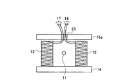
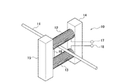
図1は、本発明の実施例1に係る電流検出装置の構成を示す概略図である。この電流検出装置は、線状の一次導体11と、この一次導体11の周囲に配置された第1コイル12、第2コイル13、第1磁性体14および第2磁性体15を備えている。
FIG. 1 is a schematic diagram illustrating a configuration of a current detection device according to Embodiment 1 of the present invention. The current detection device includes a linear
一次導体11は、本発明の「導体」に対応し、鉄、銅等といった導電性の金属により構成されている。この一次導体11は、被測定電流である負荷電流が流れることによって磁界を発生する。
The
第1コイル12および第2コイル13は、本発明の「複数のコイル」に対応し、フェノールやベークのような非導電性の芯材にエナメル線のような導線が巻きつけられて構成されている。第1コイル12および第2コイル13の各々には、一次導体11に流れる電流に応じた起電力が誘起されて電気信号として出力される。
The
なお、第1コイル12および第2コイル13は、中空構造の芯材を有するものであってもよいし、内部まで材質が充填されている芯材を有するものであってもよい。また、フェライトやパーマロイ等といった磁性体を芯材とするものであってもよい。さらに、第1コイル12および第2コイル13は、芯材を備えず、融着材料や接着剤等といった接合剤によりコイル導線同士が接合されてコイルが形成されたものであってもよい。
In addition, the
第1磁性体14および第2磁性体15は、フェライトやパーマロイ等から構成されており、第1コイル12および第2コイル13を挟み込む位置に配置されたものである。
The first
このように配置することにより、第1磁性体14は、第1コイル12および第2コイル13の一方の端面(図1中の下側の端面)に対向するように設けられ、第1コイル12と第2コイル13とを磁気的に短絡する。
By arranging in this way, the first
また、第2磁性体15は、第1コイル12および第2コイル13の他方の端面(図1中の上側の端面)に対向するように設けられ、第1コイル12および第2コイル13を磁気的に短絡する。この第2磁性体15の所定位置、具体的には第1コイル12の他方の端面に対向する位置には、第1コイル12からのコイル配線を出力端子17に導くための貫通穴21が設けられるとともに、第2コイル13の他方の端面に対向する位置には、第2コイル13からのコイル配線を出力端子18に導くための貫通穴22が設けられている。
The second
出力端子17は、一次導体11に流れる電流に応じて第1コイル12で発生された電気信号を出力する。出力端子18は、一次導体11に流れる電流に応じて第2コイル13で発生された電気信号を出力する。
The
次に、上記のように構成される電流検出装置の動作を説明する。第1コイル12および第2コイル13は、一次導体11に流れる電流により発生された磁界を受け、該電流に応じた電気信号をコイル導線に発生する。第1コイル12のコイル導線は出力端子17に接続されており、出力端子17には一次導体11に流れる電流に応じた電気信号が出力される。同様に、第2コイル13のコイル導線は出力端子18に接続されており、出力端子18には一次導体11に流れる電流に応じた電気信号が出力される。これら出力端子17および18に出力される電気信号が、一次導体11に流れる電流の大きさを表している。
Next, the operation of the current detection device configured as described above will be described. The
なお、上述した実施例1に係る電流検出装置では、第1コイル12および第2コイル13と、第1磁性体14および第2磁性体15との接続は、第1磁性体14および第2磁性体15に凹部を形成し、この凹部に第1コイル12および第2コイル13を嵌み込む構造とすることができる。また、第1コイル12および第2コイル13を、第1磁性体14および第2磁性体15に接着剤等で固定する構造としてもよい。さらには、第1コイル12および第2コイル13と、第1磁性体14および第2磁性体15とが接触している必要はなく、これらを樹脂製のケースなどに装てんすることで固定する構造としてもよい。
In the current detection device according to the first embodiment described above, the connection between the
以上説明したように、本発明の実施例1に係る電流検出装置によれば、第2磁性体15にコイル配線を通すための貫通穴21および22を形成し、第1コイル12および第2コイル13からのコイル導線を、貫通穴21および22をそれぞれ通して出力端子17および18に接続するように構成したので、配線を引き回す作業が容易になって、製造にかかる手間を減少させることができる。その結果、製造性を向上させることができるとともに、コストダウンが可能になる。
As described above, according to the current detection device according to the first embodiment of the present invention, the through
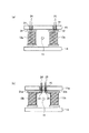
図2は、本発明の実施例2に係る電流検出装置の構成を示す概略図である。この電流検出装置は、実施例1に係る電流検出装置の第2磁性体15の構造が変更されて第2磁性体15aとされている点を除けば実施例1に係る電流検出装置と同じである。以下では、実施例1に係る電流検出装置と相違する部分を中心に説明する。
FIG. 2 is a schematic diagram illustrating a configuration of a current detection device according to Embodiment 2 of the present invention. This current detection device is the same as the current detection device according to the first embodiment except that the structure of the second
第2磁性体15aは、第1コイル12および第2コイル13の他方の端面(図2中の上側の端面)に対向するように設けられており、第1コイル12および第2コイル13を磁気的に短絡する。この第2磁性体15aの所定位置、具体的には第1コイル12の他方の端面に対向する位置以外の位置であって、且つ、第2コイル13の他方の端面に対向する位置以外の位置には、第1コイル12からのコイル配線を出力端子17に導くとともに、第2コイル13からのコイル配線を出力端子18に導くための貫通穴23が設けられている。
The second
本発明の実施例2に係る電流検出装置によれば、コイル配線を通すための1つの貫通穴23を第2磁性体15aに形成し、第1コイル12および第2コイル13からのコイル導線を、貫通穴23を通して出力端子17および18に接続するように構成したので、配線を引き回す作業が容易になって、製造にかかる手間を減少させることができ、その結果、製造性を向上させることができるとともに、コストダウンが可能になる。
According to the current detection device according to the second embodiment of the present invention, one through
また、第1コイル12および第2コイル13からのコイル配線を通す貫通穴23が、第1コイル12および第2コイル13の他方の端面に対向する位置以外の位置に設けられているので、第1コイル12および第2コイル13の他方の端部が磁性体で覆われることになり、耐外乱性能を向上させることができる。
Since the through
なお、上述した実施例2に係る電流検出装置では、第2磁性体15aに形成する貫通穴23は1つだけとしたが、第1コイル12の他方の端面に対向する位置以外の位置であって、且つ、第2コイル13の他方の端面に対向する位置以外の位置であれば、複数の貫通穴を設けることもできる。
In the current detection device according to the second embodiment described above, the number of the through
図3(a)は、本発明の実施例3に係る電流検出装置の構成を示す概略図である。この電流検出装置は、実施例1に係る電流検出装置の第1コイル12および第2コイル13のコイル導線がボビンに巻かれた構造に変更されて第1コイル12aおよび第2コイル13aとされている点を除けば実施例1に係る電流検出装置と同じである。以下では、実施例1に係る電流検出装置と相違する部分を中心に説明する。
FIG. 3A is a schematic diagram illustrating a configuration of a current detection device according to Embodiment 3 of the present invention. This current detection device is changed to a structure in which the coil conductors of the
第1コイル12aおよび第2コイル13aは、本発明の「複数のコイル」に対応する。第1コイル12aは、ボビン31にコイル導線が巻かれたボビン巻コイルによって構成され、コイル導線の巻き始めと巻き終わりはピン端子24に絡げられている。同様に、第2コイル13aは、ボビン32にコイル導線が巻かれたボビン巻コイルによって構成され、コイル導線の巻き始めと巻き終わりはピン端子25に絡げられている。ボビン31および32は、例えばPBT(polybutylene terephthalate)樹脂から構成されている。
The
本発明の実施例3に係る電流検出装置によれば、第1コイル12aおよび第2コイル13aをボビン巻コイルとしたので配線の引き回しが不要になり、製造にかかる手間を減少させることができる。その結果、製造性を向上させることができるとともに、コストダウンが可能になる。
According to the current detection device according to the third embodiment of the present invention, since the
なお、実施例3に係る電流検出装置は、以下のように変形することができる。図3(b)は、本発明の実施例3の変形例に係る電流検出装置の構成を示す概略図である。この電流検出装置は、実施例3に係る電流検出装置の第1コイル12aおよび第2コイル13aにそれぞれ含まれるボビン31および32のフランジの形状が変更されてボビン31aおよび32aとされ、第1コイル12aおよび第2コイル13aがそれぞれ第1コイル12bおよび第2コイル13bとされている点を除けば実施例3に係る電流検出装置と同じである。以下では、実施例3に係る電流検出装置と相違する部分を中心に説明する。
Note that the current detection device according to the third embodiment can be modified as follows. FIG. 3B is a schematic diagram illustrating a configuration of a current detection device according to a modification of the third embodiment of the present invention. In this current detection device, the shapes of the flanges of the
第1コイル12bおよび第2コイル13bは、本発明の「複数のコイル」に対応する。第1コイル12bのボビン31aの第2磁性体15a側のフランジは、その一部が第2磁性体15aの貫通穴23に対向する位置まで延伸されており、第1コイル12bのコイル導線は、フランジの延伸部分33から貫通穴23を介して出力端子24に接続されている。
The
また、第2コイル13bのボビン32aの第2磁性体15a側のフランジは、その一部が第2磁性体15aの貫通穴23に対向する位置まで延伸されており、第2コイル13bのコイル導線は、フランジの延伸部分34から貫通穴23を介して出力端子25に接続されている。
In addition, the flange on the second
この実施例3の変形例に係る電流検出装置によれば、実施例3に係る電流検出装置による効果に加え、更に製造にかかる手間を減少させることができる。その結果、製造性を向上させることができるとともに、コストダウンが可能になる。 According to the current detection device according to the modified example of the third embodiment, in addition to the effects of the current detection device according to the third embodiment, it is possible to further reduce the labor for manufacturing. As a result, the productivity can be improved and the cost can be reduced.
図4は、本発明の実施例4に係る電流検出装置の構成を示す概略図である。この電流検出装置は、実施例1〜実施例3に係る電流検出装置の第1磁性体および第2磁性体を同一形状にしたものである。以下では、実施例1〜実施例3に係る電流検出装置に係る電流検出装置と相違する部分を中心に説明する。 FIG. 4 is a schematic diagram illustrating a configuration of a current detection device according to Embodiment 4 of the present invention. In this current detection device, the first magnetic body and the second magnetic body of the current detection device according to the first to third embodiments are formed in the same shape. Below, it demonstrates centering on a different part from the current detection apparatus which concerns on the current detection apparatus which concerns on Example 1- Example 3. FIG.
図4(a)は、実施例1に係る電流検出装置の第1磁性体14を、第2磁性体15と同一形状を有する第1磁性体14aに変更したものである。
FIG. 4A is a diagram in which the first
図4(b)は、実施例2に係る電流検出装置の第1磁性体14を、第2磁性体15aと同一形状を有する第1磁性体14bに変更したものである。
FIG. 4B is a diagram in which the first
図4(c)は、実施例3に係る電流検出装置の第1磁性体14を、第2磁性体15と同一形状を有する第1磁性体14aに変更したものである。
FIG. 4C is a diagram in which the first
図4(d)は、実施例3の変形例に係る電流検出装置の第1磁性体14を、第2磁性体15aと同一形状を有する第1磁性体14bに変更したものである。
FIG. 4D shows a configuration in which the first
以上の図4(a)〜図4(d)に示した構成により、第1磁性体と第2磁性体とを共通の部品とすることができるので、部品の種類を減らすことができ、コストダウンが可能になる。 With the configuration shown in FIGS. 4A to 4D, the first magnetic body and the second magnetic body can be used as a common part, so the types of parts can be reduced and the cost can be reduced. Down is possible.
本発明の実施例4は、上述した実施例1〜実施例4に係る電流検出装置を利用した電力量計である。図5は、実施例4に係る電力量計の構成を示すブロック図である。この電力量計は、電流検出装置51、電圧検出部52、電力演算部53および表示部54を備えている。
Example 4 of the present invention is a watt hour meter using the current detection device according to Examples 1 to 4 described above. FIG. 5 is a block diagram illustrating the configuration of the watt-hour meter according to the fourth embodiment. This watt-hour meter includes a
電流検出装置51としては、上述した実施例1〜実施例4に係る電流検出装置のいずれかが使用される。電流検出装置51は、需要家の負荷にて使用される使用電流(A1)を検出し、当該使用電流に応じた電気信号に変換し出力する。
As the
電圧検出部52は、被測定系の電圧を検出する部分であり、電圧トランスやアテネッタ等の分圧抵抗器等により構成されており、需要家の負荷にて使用される使用電圧(V1)を検出し、当該使用電圧に正比例した低レベルの電圧信号に変換し出力する。
The
電力演算部53は、電流検出装置51により検出された導体11に流れる電流と電圧検出部52により検出された電圧とに基づいて、電力量を演算する。具体的には、電力演算部53は、デジタル乗算回路やDSP(デジタルシグナルプロセッサ)等により構成されており、電流検出装置51から出力された使用電流(A1)に関する信号と、電圧検出部52から出力された使用電圧(V1)に関する信号とを乗算し、需要家の使用電力に正比例したデータ(A1・V1)に変換する。
The
さらに電力演算部53は、使用電力に正比例したデータ(A1・V1)の演算結果を使用量データとして編集し出力する。なお、ここで使用量データとは需要家の負荷にて使用される総積算使用電力量ならびに各時間帯毎の時間帯使用量等、需要家の使用電力に関するデータをいう。
Further, the
また、電流検出装置51から出力された使用電流(A1)に関する信号は、コイルの芯材が磁性体である場合を除いて、使用電流(A1)が微分された信号に正比例した信号であるため、需要家の使用電力に正比例したデータ(A1・V1)に変換される前に、電力演算部53にて積分される。表示部54は、液晶表示器等により構成されており、使用量データを表示する。
In addition, the signal related to the used current (A1) output from the
以上説明したように、本発明の実施例5に係る電力量計によれば、製造に手間がかからない、製造性に優れ、しかもコストダウンが可能な電流検出装置を有する電力量計を実現できる。 As described above, according to the watt-hour meter according to the fifth embodiment of the present invention, it is possible to realize a watt-hour meter having a current detection device that does not require time for manufacturing, has excellent manufacturability, and can reduce costs.
11 一次導体
12、12a、12b 第1コイル
13、13a、13b 第2コイル
14、14a、14b 第1磁性体
15、15a 第2磁性体
16 接続部
17、18 出力端子
21、22、23 貫通穴
24、25 ピン端子
31、31a、32、32a ボビン
51 電流検出装置
52 電圧検出部
53 電力演算部
54 表示部
11
Claims (2)
前記導体の周囲に配置された2つのボビン巻きコイルと、
前記2つのボビン巻きコイルの一方の端面に対向するように設けられて前記2つのボビン巻きコイルを磁気的に短絡し、前記2つのボビン巻きコイルの短絡2箇所の中間付近に貫通穴を有する第1磁性体と、
前記2つのボビン巻きコイルの他方の端面に対向するように設けられて前記2つのボビン巻きコイルを磁気的に短絡し、前記2つのボビン巻きコイルの短絡2箇所の中間付近に貫通穴を有する第2磁性体と、
を備え、
前記2つのボビン巻きコイルが同一形状であり、
前記第1磁性体及び第2磁性体が同一形状であり、
前記2つのボビン巻きコイルからの出力端子が前記第1磁性体及び第2磁性体のいずれか一方の貫通穴に挿通されていることを特徴とする電流検出装置。 A conductor through which the current to be measured flows;
Two bobbin wound coils disposed around the conductor;
A second bobbin-wound coil is provided so as to face one end face of the two bobbin-wound coils, magnetically short-circuits the two bobbin-wound coils, and has a through hole in the middle of the two short-circuited locations of the two bobbin-wound coils . 1 magnetic body,
The second bobbin winding coil is provided so as to face the other end face of the two bobbin winding coils, magnetically short-circuits the two bobbin winding coils, and has a through hole in the vicinity of the middle of the two short-circuited portions of the two bobbin winding coils . Two magnetic bodies;
Equipped with a,
The two bobbin winding coils have the same shape,
The first magnetic body and the second magnetic body have the same shape,
An output terminal from the two bobbin-wound coils is inserted into one through hole of either the first magnetic body or the second magnetic body .
前記導体に発生する電圧を検出する電圧検出部と、
前記電流検出装置により検出された電流と、前記電圧検出部で検出された電圧とに基づき電力又は電力量を算出する電力演算部と、
を備えることを特徴とする電力量計。 A current detection device according to claim 1 ;
A voltage detection unit for detecting a voltage generated in the conductor;
A power calculator that calculates power or power based on the current detected by the current detector and the voltage detected by the voltage detector;
A watt-hour meter comprising:
Priority Applications (9)
| Application Number | Priority Date | Filing Date | Title |
|---|---|---|---|
| JP2011147461A JP5820164B2 (en) | 2011-07-01 | 2011-07-01 | Current detection device and watt-hour meter using the same |
| PCT/JP2011/077958 WO2013005352A1 (en) | 2011-07-01 | 2011-12-02 | Current detector and electricity meter |
| EP11868916.5A EP2728366B1 (en) | 2011-07-01 | 2011-12-02 | Current detector and electricity meter |
| CA2840021A CA2840021C (en) | 2011-07-01 | 2011-12-02 | Current detection device and electricity meter |
| US14/127,354 US9354258B2 (en) | 2011-07-01 | 2011-12-02 | Current detection device and electricity meter |
| CN201180071779.0A CN103620421B (en) | 2011-07-01 | 2011-12-02 | Current sensing means and voltameter |
| AU2011372577A AU2011372577B2 (en) | 2011-07-01 | 2011-12-02 | Current detection device and electricity meter |
| BR112013033144A BR112013033144A2 (en) | 2011-07-01 | 2011-12-02 | current detection device and electricity meter |
| HK14108641.0A HK1195363A1 (en) | 2011-07-01 | 2014-08-25 | Current detector and electricity meter |
Applications Claiming Priority (1)
| Application Number | Priority Date | Filing Date | Title |
|---|---|---|---|
| JP2011147461A JP5820164B2 (en) | 2011-07-01 | 2011-07-01 | Current detection device and watt-hour meter using the same |
Publications (3)
| Publication Number | Publication Date |
|---|---|
| JP2013015370A JP2013015370A (en) | 2013-01-24 |
| JP2013015370A5 JP2013015370A5 (en) | 2014-07-17 |
| JP5820164B2 true JP5820164B2 (en) | 2015-11-24 |
Family
ID=47436721
Family Applications (1)
| Application Number | Title | Priority Date | Filing Date |
|---|---|---|---|
| JP2011147461A Active JP5820164B2 (en) | 2011-07-01 | 2011-07-01 | Current detection device and watt-hour meter using the same |
Country Status (9)
| Country | Link |
|---|---|
| US (1) | US9354258B2 (en) |
| EP (1) | EP2728366B1 (en) |
| JP (1) | JP5820164B2 (en) |
| CN (1) | CN103620421B (en) |
| AU (1) | AU2011372577B2 (en) |
| BR (1) | BR112013033144A2 (en) |
| CA (1) | CA2840021C (en) |
| HK (1) | HK1195363A1 (en) |
| WO (1) | WO2013005352A1 (en) |
Families Citing this family (7)
| Publication number | Priority date | Publication date | Assignee | Title |
|---|---|---|---|---|
| US9113570B2 (en) * | 2012-10-31 | 2015-08-18 | Tyco Electronics Services Gmbh | Planar electronic device having a magnetic component |
| US9810718B2 (en) * | 2015-03-13 | 2017-11-07 | Eaton Corporation | Wire wound resistor arrangement and sensing arrangement including the same |
| GB201518372D0 (en) * | 2015-10-16 | 2015-12-02 | Johnson Electric Sa | Current determining device and methods |
| FR3053795B1 (en) * | 2016-07-08 | 2019-11-08 | Schneider Electric Industries Sas | APPARATUS FOR MEASURING ELECTRIC CURRENTS IN ELECTRICAL CONDUCTORS |
| CN108572344A (en) | 2017-03-10 | 2018-09-25 | 恩智浦美国有限公司 | Detect the device and method of Current Transformer Secondary side disconnecting |
| WO2019070583A1 (en) | 2017-10-02 | 2019-04-11 | ABB Schweiz AB | Flux absorber for power line device |
| JP2020148640A (en) * | 2019-03-14 | 2020-09-17 | 株式会社東芝 | Current detector |
Family Cites Families (52)
| Publication number | Priority date | Publication date | Assignee | Title |
|---|---|---|---|---|
| FR2584193B1 (en) * | 1985-06-28 | 1987-08-07 | Telemecanique Electrique | INDUCTIVE SENSOR FOR CURRENT MEASUREMENT |
| US4749940A (en) * | 1986-12-22 | 1988-06-07 | General Electric Company | Folded bar current sensor |
| US4952853A (en) * | 1988-08-24 | 1990-08-28 | General Electric Company | Method and apparatus for sensing direct current of one polarity in a conductor and electronically commutated motor control responsive to sensed motor current |
| US5066904A (en) * | 1988-10-18 | 1991-11-19 | General Electric Company | Coaxial current sensors |
| DK0438616T3 (en) * | 1990-01-23 | 1994-08-29 | Siemens Ag | Power voltage converter for electronic household counters |
| US5563506A (en) * | 1990-07-10 | 1996-10-08 | Polymeters Response International Limited | Electricity meters using current transformers |
| FR2678069A1 (en) * | 1991-06-18 | 1992-12-24 | Commissariat Energie Atomique | CURRENT SENSOR USING A DIRECTIONAL RESONANCE MAGNETOMETER. |
| JP2698722B2 (en) * | 1991-10-22 | 1998-01-19 | シーケーディ株式会社 | solenoid valve |
| US5343143A (en) * | 1992-02-11 | 1994-08-30 | Landis & Gyr Metering, Inc. | Shielded current sensing device for a watthour meter |
| FR2692074B1 (en) * | 1992-06-05 | 1994-07-22 | Alsthom Gec | ROGOWSKI COIL. |
| ATE134449T1 (en) | 1993-03-05 | 1996-03-15 | Deutsche Zaehler Gmbh | CURRENT TRANSFORMER, IN PARTICULAR FOR AN ELECTRONIC ELECTRICITY METER |
| US5430613A (en) * | 1993-06-01 | 1995-07-04 | Eaton Corporation | Current transformer using a laminated toroidal core structure and a lead frame |
| US5453681A (en) * | 1993-07-06 | 1995-09-26 | General Electric Company | Current sensor employing a mutually inductive current sensing scheme |
| US5486755A (en) * | 1994-12-27 | 1996-01-23 | General Electric Company | Electronic meter having anti-tampering magnetic shield |
| CH690464A5 (en) * | 1995-02-23 | 2000-09-15 | Lem Liaisons Electron Mec | inductive measurement device for measurement of AC components superimposed on a high DC current. |
| US5841272A (en) * | 1995-12-20 | 1998-11-24 | Sundstrand Corporation | Frequency-insensitive current sensor |
| US5917401A (en) * | 1997-02-26 | 1999-06-29 | Sundstrand Corporation | Conductive bus member and method of fabricating same |
| US5839185A (en) * | 1997-02-26 | 1998-11-24 | Sundstrand Corporation | Method of fabricating a magnetic flux concentrating core |
| US5834932A (en) * | 1997-03-17 | 1998-11-10 | May; Gregory R. | Watthour meter system |
| US6016054A (en) * | 1997-07-14 | 2000-01-18 | Siemens Transmission & Distribution, Llc | Watt hour meter registration calibration method and apparatus |
| US6184672B1 (en) * | 1997-08-15 | 2001-02-06 | General Electric Company | Current sensor assembly with electrostatic shield |
| US6008711A (en) * | 1998-01-09 | 1999-12-28 | Siemens Power Transmission & Distribution | Method and arrangement for securing a current transformer to an electric utility meter housing |
| US6043641A (en) * | 1998-02-17 | 2000-03-28 | Singer; Jerome R. | Method and apparatus for rapid determinations of voltage and current in wires and conductors |
| WO1999046607A1 (en) * | 1998-03-13 | 1999-09-16 | Florida International University | Apparatus for measuring high frequency currents |
| US6130599A (en) * | 1999-08-03 | 2000-10-10 | Eaton Corporation | Electrical current sensing apparatus |
| EP1074846B1 (en) * | 1999-08-04 | 2007-02-14 | Schneider Electric Industries SAS | Current sensor for an electrical device |
| GB9918539D0 (en) * | 1999-08-06 | 1999-10-06 | Sentec Ltd | Planar current transformer |
| JP2002082134A (en) * | 2000-09-08 | 2002-03-22 | Mitsubishi Heavy Ind Ltd | Current sensor, current-measuring method and switch circuit |
| US6456061B1 (en) * | 2000-11-21 | 2002-09-24 | General Electric Company | Calibrated current sensor |
| US6774759B2 (en) * | 2001-05-18 | 2004-08-10 | Marconi Intellectual Property (Ringfence), Inc. | Combined fuse holder and current monitor |
| JP2003130894A (en) * | 2001-10-29 | 2003-05-08 | Toshiba Corp | Current transformer |
| US6680608B2 (en) * | 2002-02-27 | 2004-01-20 | Mcgraw-Edison Company | Measuring current through an electrical conductor |
| JP2003315373A (en) * | 2002-04-18 | 2003-11-06 | Toshiba Corp | Current detection device and semiconductor device |
| US7180717B2 (en) * | 2002-07-12 | 2007-02-20 | Cooper Technologies Company | Electrical network protection system |
| JP4055196B2 (en) | 2003-07-17 | 2008-03-05 | 有限会社日間賀電子 | Current detection device |
| JP3831368B2 (en) | 2003-09-25 | 2006-10-11 | スミダコーポレーション株式会社 | Leakage transformer |
| US7154368B2 (en) * | 2003-10-15 | 2006-12-26 | Actown Electricoil, Inc. | Magnetic core winding method, apparatus, and product produced therefrom |
| JP4007339B2 (en) * | 2003-11-07 | 2007-11-14 | 株式会社デンソー | AC motor and its control device |
| JP2005268447A (en) * | 2004-03-17 | 2005-09-29 | Matsushita Electric Ind Co Ltd | Multilayer circuit board with built-in coil |
| DE102004021495A1 (en) * | 2004-04-30 | 2005-11-24 | Vacuumschmelze Gmbh & Co. Kg | current sensor |
| US7227442B2 (en) * | 2005-04-01 | 2007-06-05 | Schweitzer Engineering Laboratories, Inc. | Precision printed circuit board based rogowski coil and method for manufacturing same |
| JP4674533B2 (en) * | 2005-12-02 | 2011-04-20 | パナソニック電工株式会社 | AC current detection coil |
| US7638999B2 (en) * | 2006-04-07 | 2009-12-29 | Cooper Technologies Company | Protective relay device, system and methods for Rogowski coil sensors |
| US7532000B2 (en) * | 2006-08-03 | 2009-05-12 | The Boeing Company | Method and system for measurement of current flows in fastener arrays |
| US7564233B2 (en) * | 2006-11-06 | 2009-07-21 | Cooper Technologies Company | Shielded Rogowski coil assembly and methods |
| US7538541B2 (en) * | 2006-11-06 | 2009-05-26 | Cooper Technologies Company | Split Rogowski coil current measuring device and methods |
| FR2920881B1 (en) * | 2007-09-10 | 2010-03-05 | Socomec Sa | DEVICE FOR MEASURING THE INTENSITY OF AN ELECTRICAL CURRENT AND ELECTRICAL APPARATUS COMPRISING SUCH A DEVICE. |
| JP5366418B2 (en) * | 2008-03-24 | 2013-12-11 | 東光東芝メーターシステムズ株式会社 | Current detector and watt-hour meter using the same |
| JP5058925B2 (en) * | 2008-09-18 | 2012-10-24 | 矢崎総業株式会社 | Current sensor |
| JP2010256141A (en) * | 2009-04-23 | 2010-11-11 | Toshiba Toko Meter Systems Co Ltd | Current detection apparatus and watt-hour meter using the same |
| JP5614967B2 (en) * | 2009-10-22 | 2014-10-29 | 東光東芝メーターシステムズ株式会社 | Current detection device and watt-hour meter using the same |
| JP5375874B2 (en) * | 2011-05-13 | 2013-12-25 | 株式会社デンソー | Motor drive device |
-
2011
- 2011-07-01 JP JP2011147461A patent/JP5820164B2/en active Active
- 2011-12-02 CN CN201180071779.0A patent/CN103620421B/en active Active
- 2011-12-02 US US14/127,354 patent/US9354258B2/en active Active
- 2011-12-02 CA CA2840021A patent/CA2840021C/en active Active
- 2011-12-02 BR BR112013033144A patent/BR112013033144A2/en not_active Application Discontinuation
- 2011-12-02 AU AU2011372577A patent/AU2011372577B2/en not_active Ceased
- 2011-12-02 EP EP11868916.5A patent/EP2728366B1/en not_active Not-in-force
- 2011-12-02 WO PCT/JP2011/077958 patent/WO2013005352A1/en active Application Filing
-
2014
- 2014-08-25 HK HK14108641.0A patent/HK1195363A1/en not_active IP Right Cessation
Also Published As
| Publication number | Publication date |
|---|---|
| AU2011372577B2 (en) | 2015-09-03 |
| CA2840021A1 (en) | 2013-01-10 |
| CN103620421B (en) | 2016-02-24 |
| HK1195363A1 (en) | 2014-11-07 |
| US9354258B2 (en) | 2016-05-31 |
| EP2728366A1 (en) | 2014-05-07 |
| US20140111190A1 (en) | 2014-04-24 |
| JP2013015370A (en) | 2013-01-24 |
| CA2840021C (en) | 2018-01-23 |
| CN103620421A (en) | 2014-03-05 |
| AU2011372577A1 (en) | 2014-01-09 |
| EP2728366B1 (en) | 2018-10-03 |
| BR112013033144A2 (en) | 2017-01-24 |
| EP2728366A4 (en) | 2015-03-25 |
| WO2013005352A1 (en) | 2013-01-10 |
Similar Documents
| Publication | Publication Date | Title |
|---|---|---|
| JP5820164B2 (en) | Current detection device and watt-hour meter using the same | |
| US7626376B2 (en) | Electric current detector having magnetic detector | |
| JP6024814B1 (en) | Inductance element for magnetic sensor and current sensor including the same | |
| JP2011247699A (en) | Current sensor with electric leakage detection function | |
| JP5162376B2 (en) | Current sensor, watt-hour meter | |
| JP2010256141A (en) | Current detection apparatus and watt-hour meter using the same | |
| JPS63306608A (en) | Instrument transformer for measuring current flowing through electric conductor | |
| JP2016148597A (en) | Current sensor | |
| JP2006105955A (en) | Device for sensing energization of electrical equipment | |
| JP5633917B2 (en) | Current detection device and watt-hour meter using the same | |
| JP5614967B2 (en) | Current detection device and watt-hour meter using the same | |
| JP5869785B2 (en) | Current detection device and watt-hour meter | |
| JP5731876B2 (en) | Current detection device and watt-hour meter using the same | |
| JP2011220952A (en) | Current detection device and watt-hour meter using the same | |
| WO2012060069A1 (en) | Current sensor | |
| US20110050221A1 (en) | Coil design for miniaturized fluxgate sensors | |
| JP2018146388A (en) | Current sensor and electricity meter | |
| JP5084680B2 (en) | Current detection device and watt-hour meter using the same | |
| JP6771179B2 (en) | Power measurement system | |
| JP2005221342A (en) | Coil-type current sensor | |
| JP2014202737A (en) | Current sensor | |
| JPS58137Y2 (en) | electricity meter | |
| KR101507455B1 (en) | Line Filter With Current Sensor | |
| JP2008267832A (en) | Electric current measuring instrument | |
| JP2022074306A (en) | Current sensor and electricity meter |
Legal Events
| Date | Code | Title | Description |
|---|---|---|---|
| A521 | Request for written amendment filed |
Free format text: JAPANESE INTERMEDIATE CODE: A523 Effective date: 20140602 |
|
| A621 | Written request for application examination |
Free format text: JAPANESE INTERMEDIATE CODE: A621 Effective date: 20140602 |
|
| A131 | Notification of reasons for refusal |
Free format text: JAPANESE INTERMEDIATE CODE: A131 Effective date: 20150303 |
|
| A521 | Request for written amendment filed |
Free format text: JAPANESE INTERMEDIATE CODE: A523 Effective date: 20150430 |
|
| TRDD | Decision of grant or rejection written | ||
| A01 | Written decision to grant a patent or to grant a registration (utility model) |
Free format text: JAPANESE INTERMEDIATE CODE: A01 Effective date: 20150929 |
|
| A61 | First payment of annual fees (during grant procedure) |
Free format text: JAPANESE INTERMEDIATE CODE: A61 Effective date: 20151002 |
|
| R150 | Certificate of patent or registration of utility model |
Ref document number: 5820164 Country of ref document: JP Free format text: JAPANESE INTERMEDIATE CODE: R150 |
|
| S531 | Written request for registration of change of domicile |
Free format text: JAPANESE INTERMEDIATE CODE: R313531 |
|
| R350 | Written notification of registration of transfer |
Free format text: JAPANESE INTERMEDIATE CODE: R350 |
|
| R250 | Receipt of annual fees |
Free format text: JAPANESE INTERMEDIATE CODE: R250 |
|
| R250 | Receipt of annual fees |
Free format text: JAPANESE INTERMEDIATE CODE: R250 |
|
| R250 | Receipt of annual fees |
Free format text: JAPANESE INTERMEDIATE CODE: R250 |
|
| R250 | Receipt of annual fees |
Free format text: JAPANESE INTERMEDIATE CODE: R250 |
|
| R250 | Receipt of annual fees |
Free format text: JAPANESE INTERMEDIATE CODE: R250 |
|
| R250 | Receipt of annual fees |
Free format text: JAPANESE INTERMEDIATE CODE: R250 |