JP5818737B2 - Brushless motor - Google Patents
Brushless motor Download PDFInfo
- Publication number
- JP5818737B2 JP5818737B2 JP2012092148A JP2012092148A JP5818737B2 JP 5818737 B2 JP5818737 B2 JP 5818737B2 JP 2012092148 A JP2012092148 A JP 2012092148A JP 2012092148 A JP2012092148 A JP 2012092148A JP 5818737 B2 JP5818737 B2 JP 5818737B2
- Authority
- JP
- Japan
- Prior art keywords
- bus bar
- phase
- phase bus
- coil
- brushless motor
- Prior art date
- Legal status (The legal status is an assumption and is not a legal conclusion. Google has not performed a legal analysis and makes no representation as to the accuracy of the status listed.)
- Expired - Fee Related
Links
Images


Classifications
-
- H—ELECTRICITY
- H02—GENERATION; CONVERSION OR DISTRIBUTION OF ELECTRIC POWER
- H02K—DYNAMO-ELECTRIC MACHINES
- H02K3/00—Details of windings
- H02K3/04—Windings characterised by the conductor shape, form or construction, e.g. with bar conductors
- H02K3/28—Layout of windings or of connections between windings
-
- H—ELECTRICITY
- H02—GENERATION; CONVERSION OR DISTRIBUTION OF ELECTRIC POWER
- H02K—DYNAMO-ELECTRIC MACHINES
- H02K3/00—Details of windings
- H02K3/46—Fastening of windings on the stator or rotor structure
- H02K3/52—Fastening salient pole windings or connections thereto
- H02K3/521—Fastening salient pole windings or connections thereto applicable to stators only
- H02K3/522—Fastening salient pole windings or connections thereto applicable to stators only for generally annular cores with salient poles
-
- H—ELECTRICITY
- H02—GENERATION; CONVERSION OR DISTRIBUTION OF ELECTRIC POWER
- H02K—DYNAMO-ELECTRIC MACHINES
- H02K2203/00—Specific aspects not provided for in the other groups of this subclass relating to the windings
- H02K2203/09—Machines characterised by wiring elements other than wires, e.g. bus rings, for connecting the winding terminations
Landscapes
- Engineering & Computer Science (AREA)
- Power Engineering (AREA)
- Insulation, Fastening Of Motor, Generator Windings (AREA)
Description
この発明は、例えば自動二輪車等に用いられるブラシレスモータに関するものである。 The present invention relates to a brushless motor used in, for example, a motorcycle.
一般に、インナーロータ型のブラシレスモータは、モータケースに内嵌固定されたステータと、モータケースの径方向中央に配置されステータに対して回転自在に支持されたロータとを有している。ロータの外周面には、複数の永久磁石が設けられている。ステータは、略円筒状のステータコアと、このステータコアから径方向内側に突設された複数のティースとを備えている。 In general, an inner rotor type brushless motor has a stator that is fitted and fixed in a motor case, and a rotor that is disposed at the center in the radial direction of the motor case and is rotatably supported by the stator. A plurality of permanent magnets are provided on the outer peripheral surface of the rotor. The stator includes a substantially cylindrical stator core and a plurality of teeth projecting radially inward from the stator core.
各ティースには、電気的絶縁材である樹脂製のインシュレータが装着され、このインシュレータを介してコイルが巻装されている。そして、コイルに外部電源からの電力が供給されると、コイルに発生する磁束と永久磁石との間に吸引力、または反発力が生じロータが回転する。 Each tooth is provided with a resin insulator, which is an electrically insulating material, and a coil is wound through the insulator. When power from an external power source is supplied to the coil, an attractive force or a repulsive force is generated between the magnetic flux generated in the coil and the permanent magnet, and the rotor rotates.
ここで、コイルへの給電手段として、小型化や組付け性の向上を図るために、略円環状に形成された樹脂モールド体に、金属製の複数のバスバーを互いに電気的に絶縁された状態で埋設したバスバーユニットを用いる場合がある(例えば、特許文献1参照)。 Here, as a means for supplying power to the coil, a state in which a plurality of metal bus bars are electrically insulated from each other in a resin mold body formed in a substantially annular shape in order to reduce the size and improve the assemblability. In some cases, a bus bar unit embedded in (1) is used.
特許文献1に記載のバスバーユニットは、平板状の各相(U相、V相、W相の三相)のバスバーと中性点用バスバーとが軸方向に離間した状態で積層され、樹脂モールド体によりモールドされている。樹脂モールド体の外周面には、ステータコア側に向かって突出する脚部が一体成形されている一方、インシュレータには、脚部に対応する部位に脚部を嵌合可能な凹部が形成されている。この凹部に脚部を嵌合させるように、インシュレータ上にバスバーユニットを重ねることにより、バスバーユニットが固定される。 The bus bar unit described in Patent Document 1 is laminated in such a state that a flat-phase bus bar (three phases of U phase, V phase, and W phase) and a neutral point bus bar are separated in the axial direction. Molded by the body. The outer peripheral surface of the resin mold body is integrally formed with a leg portion protruding toward the stator core side, while the insulator is formed with a concave portion capable of fitting the leg portion at a portion corresponding to the leg portion. . The bus bar unit is fixed by stacking the bus bar unit on the insulator so that the leg portion is fitted in the recess.
また、各相のバスバーに突設されている各相用端子と、中性点用バスバーに突設されている中性点用端子とは、それぞれ樹脂モールド体の外周面から径方向外側に向かって放射状に突出した状態となっている。
各相用端子には、各相コイルの巻き始め端部が接続される一方、中性点用端子には各相コイルの巻き終わり端部が接続される。これにより、各相コイルは、所謂スター結線方式にて結線されている。
In addition, each phase terminal projecting from each phase bus bar and each neutral point terminal projecting from the neutral point bus bar are directed radially outward from the outer peripheral surface of the resin mold body. And projecting radially.
Each phase terminal is connected to the winding start end of each phase coil, while the neutral point terminal is connected to the winding end of each phase coil. Thereby, each phase coil is connected by what is called a star connection system.
ところで、上述のブラシレスモータのさらなる小型化、軽量化の要望が高い。とりわけ、自動二輪車にあっては、車体が傾くので、車体側方への傾斜角(バンク角)を考慮し、自動二輪車に搭載されるブラシレスモータの軸短化が望まれている。
しかしながら、上述の従来技術にあっては、インシュレータ上にバスバーユニットを重ねるようにしてこのバスバーユニットを固定しているので、ステータコアからバスバーユニットまでの高さを抑えにくい。このため、ブラシレスモータの軸長が長くなり、大型化してしまうという課題がある。
By the way, there is a high demand for further miniaturization and weight reduction of the brushless motor described above. In particular, in a motorcycle, since the vehicle body is inclined, it is desired to shorten the shaft of a brushless motor mounted on the motorcycle in consideration of an inclination angle (bank angle) toward the vehicle body side.
However, in the above-described prior art, since the bus bar unit is fixed so as to overlap the bus bar unit on the insulator, it is difficult to suppress the height from the stator core to the bus bar unit. For this reason, the axial length of a brushless motor becomes long and there exists a subject that it will enlarge.
そこで、この発明は、上述した事情に鑑みてなされたものであって、小型化を図ることができるブラシレスモータを提供するものである。 The present invention has been made in view of the above-described circumstances, and provides a brushless motor that can be reduced in size.
上記の課題を解決するために、本発明に係るブラシレスモータは、ステータコアと、このステータコアの径方向内側に配置され、前記ステータコアに対して回転自在に支持されているロータと、前記ステータコアにインシュレータを介して巻回された複数の相のコイルに、給電を行うためのリング状のバスバーユニットとを備えたブラシレスモータであって、前記バスバーユニットは、それぞれ前記コイルの一端と接続される2つの相端子を有すると共に、外部電源と電気的に接続される給電部を有する湾曲状の第1相用バスバー、第2相用バスバー、および第3相用バスバーと、前記第1相用バスバー、前記第2相用バスバー、および前記第3相用バスバーのそれぞれを保持する絶縁部材からなるリング状のバスバーホルダとを備え、前記バスバーホルダの内周面の直径を、前記インシュレータの外周面の直径よりも大きく設定し、前記インシュレータよりも径方向外側に、前記バスバーユニットを配置し、前記第1相用バスバー、前記第2相用バスバー、および前記第3相用バスバーのそれぞれは、帯状の金属板の厚さ方向を湾曲形成して成ると共に、前記第1相用バスバー、および前記第3相用バスバーは、それぞれの両端側に前記相端子が設けられており、且つ2つの前記相端子の一方の相端子よりも端部側に前記給電部が設けられており、前記第2相用バスバーは、両端側に前記相端子が設けられており、且つ2つの前記相端子の間に前記給電部が設けられており、前記第1相用バスバー、前記第2相用バスバー、および前記第3相用バスバーは、前記第2相用バスバーが間に位置するように、それぞれ径方向に並んで配置され、前記第1相用バスバー、および前記第3相用バスバーの少なくとも何れか一方は、2つの前記相端子の間で、且つ周方向の途中から曲率半径が変化するように連続的に形成されていることを特徴とする。 In order to solve the above problems, a brushless motor according to the present invention includes a stator core, a rotor that is disposed radially inside the stator core, and is rotatably supported with respect to the stator core, and an insulator provided in the stator core. the coils of a plurality of phases are wound through, a brushless motor that includes a ring-shaped bus bar unit for feeding current, the bus bar unit includes two connected to one end of the previous SL coil respectively A curved first- phase bus bar , a second-phase bus bar, and a third-phase bus bar having a phase terminal and having a power feeding portion electrically connected to an external power source , the first-phase bus bar, for the second phase busbar, and a ring-shaped bus bar holder made of an insulating member for holding each of said third phase bus bar, wherein The diameter of the inner peripheral surface of Subahoruda, set larger than the diameter of the outer circumferential surface of the insulator, radially outward from the insulator, the busbar unit arranged, the first phase bus bar, for the second phase bus bar, and wherein each of the third-phase bus bar, the thickness direction of the strip-shaped metal plate is curved formation Rutotomoni, the first phase bus bar, and the third phase bus bar are each at both ends The phase terminal is provided, and the power feeding portion is provided on the end side of one of the two phase terminals, and the second phase bus bar is provided on both ends of the phase terminal. And the power feeding section is provided between the two phase terminals, and the first-phase bus bar, the second-phase bus bar, and the third-phase bus bar are connected to the second phase terminal. Auspicious bus bar So as to be positioned between, is arranged in each radial direction, said first phase bus bar, and at least one of the third phase busbar is between two of the phase terminals, and the circumferential direction of the It is formed continuously so that the radius of curvature changes from the middle.
このように構成することで、インシュレータとバスバーユニットを軸方向でラップさせることができる。このため、この分、ステータコアからバスバーユニットまでの高さを抑えることができ、この結果、ブラシレスモータの軸方向の長さを短くすることができ、ブラシレスモータの小型化を図ることができる。
また、インシュレータよりも径方向外側にバスバーユニットを配置することから、ステータコアの軸方向上方に空間を確保しやすく、コイルで発生した熱の放熱効果を高めることができる。このため、ブラシレスモータの温度上昇を抑えることができ、ブラシレスモータのモータ効率を高めることが可能になる。
さらに、ステータコアの軸方向上方に空間が確保できれば、この空間にコイルの端末部を引き出し、コイルの端末部とバスバーユニットの各端子を接続させることが可能になる。このため、コイルの端末部の配索経路を単純化することができる。
そして、複数の相用バスバーの径方向の間に、余分なスペースが形成されてしまうのを抑制できる。このため、バスバーユニットの径方向を縮径化でき、この結果、ブラシレスモータを小型化することが可能になる。
By comprising in this way, an insulator and a bus-bar unit can be wrapped in an axial direction. For this reason, the height from the stator core to the bus bar unit can be suppressed correspondingly, and as a result, the axial length of the brushless motor can be shortened, and the brushless motor can be miniaturized.
In addition, since the bus bar unit is disposed on the radially outer side of the insulator, it is easy to secure a space above the stator core in the axial direction, and the heat dissipation effect of the heat generated by the coil can be enhanced. For this reason, the temperature rise of a brushless motor can be suppressed and it becomes possible to raise the motor efficiency of a brushless motor.
Furthermore, if a space can be secured above the stator core in the axial direction, it is possible to draw the terminal portion of the coil into this space and connect the terminal portion of the coil and each terminal of the bus bar unit. For this reason, the routing route of the terminal part of a coil can be simplified.
And it can suppress that an extra space is formed between the radial directions of a plurality of phase bus bars. For this reason, the radial direction of the bus bar unit can be reduced, and as a result, the brushless motor can be reduced in size.
本発明に係るブラシレスモータは、前記ステータコアは、ステータハウジングに圧入されており、前記ステータハウジングには、前記バスバーユニットに対応する位置に、前記バスバーユニットを受け入れる拡径部が段差によって形成されていることを特徴とする。 In the brushless motor according to the present invention , the stator core is press-fitted into a stator housing, and the stator housing is formed with a stepped portion at a position corresponding to the bus bar unit by a step. It is characterized by that.
本発明に係るブラシレスモータは、前記バスバーホルダは、リング状に形成されたホルダ本体を有し、このホルダ本体に、軸方向一方側から前記第1相用バスバー、前記第2相用バスバー、および前記第3相用バスバーを挿入可能な複数の溝が径方向に並んで形成されており、各溝の開口縁の少なくとも一部に、前記第1相用バスバー、前記第2相用バスバー、および前記第3相用バスバーの抜けを防止するための抜け止め爪が形成されていることを特徴とする。 In the brushless motor according to the present invention, the bus bar holder has a holder main body formed in a ring shape, and the first main bus bar, the second phase bus bar, and the second phase bus bar, A plurality of grooves into which the third phase bus bar can be inserted are formed side by side in the radial direction, and the first phase bus bar, the second phase bus bar, and A retaining claw for preventing the third phase bus bar from coming off is formed.
このように構成することで、複数の相用バスバーを、従来のように、樹脂モールド体によりモールドすることがなくなるので、モールドするための大掛かりな設備が必要なくなる。このため、バスバーユニットを製造するための設備が簡素化でき、バスバーユニットの製造コストを低減できる。
また、各溝と、複数の相用バスバーとの寸法公差を高精度に管理することなく、各相用バスバーの溝からの抜けを防止することができる。このため、バスバーユニットの製造コストを低減できる。
さらに、複数の相用バスバーの形状を、溝の形状と異なる形状とし、各相用バスバーの弾性で保持する場合に対し、確実に各相用バスバーを保持することが可能になる。
By comprising in this way, since the several phase bus bar is not molded by the resin mold body like the past, the large installation for molding becomes unnecessary. For this reason, the equipment for manufacturing the bus bar unit can be simplified, and the manufacturing cost of the bus bar unit can be reduced.
Further, it is possible to prevent each phase bus bar from coming out of the groove without managing the dimensional tolerance between each groove and the plurality of phase bus bars with high accuracy. For this reason, the manufacturing cost of a bus-bar unit can be reduced.
Furthermore, it is possible to reliably hold each phase bus bar as compared to the case where the shape of the plurality of phase bus bars is different from the shape of the groove and is held by the elasticity of each phase bus bar.
本発明に係るブラシレスモータは、前記ステータコアの各ティースに、それぞれ2本の前記コイルが並列回路を成すように巻回されていることを特徴とする。
このように構成することで、コイルの線径を細径化しながら各ティースに巻回されるコイルの総抵抗を抑制することができる。このため、コイルを細径化できる分、巻回作業を容易にすることができる。
The brushless motor according to the present invention is characterized in that two coils are wound around each tooth of the stator core so as to form a parallel circuit.
By comprising in this way, the total resistance of the coil wound around each tooth can be suppressed while reducing the wire diameter of the coil. For this reason, winding work can be facilitated as much as the diameter of the coil can be reduced.
本発明に係るブラシレスモータは、前記バスバーユニットはグロメットを備え、前記グロメットは、前記グロメットの一方の平面から形成され、液状シール材を注入するためのガスケット流通孔と、前記グロメットの他方の平面の全域に渡って形成され、前記ガスケット流通孔に連通するガスケット溜り溝とを備えていることを特徴とする。
このように構成することで、ガスケット流通孔に液状シール材を注入すると、この液状シール材が、ガスケット流通孔を通ってガスケット溜り溝に充填される。このため、グロメットを所定の位置に組み付けた後、グロメットの他方の平面に液状シール材を塗布する場合であっても、グロメットの他方の平面に液状シール材を行き渡らせることができる。
In the brushless motor according to the present invention, the bus bar unit includes a grommet, and the grommet is formed from one plane of the grommet, and has a gasket circulation hole for injecting a liquid sealing material, and the other plane of the grommet. A gasket retaining groove formed over the entire region and communicating with the gasket circulation hole is provided.
With this configuration, when the liquid sealing material is injected into the gasket circulation hole, the liquid sealing material is filled into the gasket retaining groove through the gasket circulation hole. Therefore, even when the liquid sealing material is applied to the other plane of the grommet after the grommet is assembled at a predetermined position, the liquid sealing material can be distributed to the other plane of the grommet.
本発明によれば、インシュレータとバスバーユニットを軸方向でラップさせることができる。このため、この分、ステータコアからバスバーユニットまでの高さを抑えることができ、この結果、ブラシレスモータの軸方向の長さを短くすることができ、ブラシレスモータの小型化を図ることができる。 According to the present invention, the insulator and the bus bar unit can be wrapped in the axial direction. For this reason, the height from the stator core to the bus bar unit can be suppressed correspondingly, and as a result, the axial length of the brushless motor can be shortened, and the brushless motor can be miniaturized.
(ブラシレスモータ)
次に、この発明の実施形態を図面に基づいて説明する。
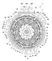
図1は、ブラシレスモータ1の中心軸Oを含む断面図である。
図1に示すように、ブラシレスモータ1は、例えば、電動自動二輪車に用いられるものであって、有底筒状のステータハウジング2に圧入されたステータ3と、ステータ3に対して回転自在に設けられたロータ4と、ステータ3に巻回されているコイル12に電流を供給するためのバスバーユニット50と、ステータハウジング2の開口部2aを閉塞するように設けられているブラケット7とを有している。
(Brushless motor)
Next, embodiments of the present invention will be described with reference to the drawings.
FIG. 1 is a cross-sectional view including the central axis O of the brushless motor 1.
As shown in FIG. 1, a brushless motor 1 is used in, for example, an electric motorcycle, and is provided so as to be rotatable with respect to a
ステータハウジング2の底部2bには、径方向中央に、軸方向外側に突出するボス部2cが形成され、ここに軸受5が圧入されている。この軸受け5は、ロータ4の回転シャフト6を回転自在に支持するためのものである。
尚、以下の説明では、ステータハウジング2の開口側(図1における左側)を軸方向の一方側とし、底部2b側(図1における右側)を軸方向の他方側として説明する場合がある。
A
In the following description, the opening side (left side in FIG. 1) of the
図2は、ブラシレスモータ1のブラケット7を取り外した状態の平面図、図3は、分割コア61の平面図である。
図1〜図3に示すように、ステータ3は、略円筒状のステータコア10を有しており、このステータコア10の外周面がステータハウジング2の筒部2dの内周面に圧入されている。
ここで、ステータコア10は、周方向に分割可能な分割コア方式が用いられている。ステータコア10から分割された分割コア61は、例えば磁性材料から成る板材を軸方向に複数枚積層して形成されたものであって、周方向に延びるコア本体62を有している。コア本体62は、ステータコア10の環状の磁路を形成する部分であり、且つステータハウジング2の内周面に内嵌される部分であって、軸方向平面視で略円弧状に形成されている。
FIG. 2 is a plan view of the brushless motor 1 with the
As shown in FIGS. 1 to 3, the
Here, the
コア本体62の周方向の両端部は、他のコア本体62に圧入によって連結される連結部63a,63bになっている。一方の連結部63aは凸形状を有し、他方の連結部63bは、一方の連結部63aを受け入れ可能な凹形状を有している。これにより、各コア本体62を連結して略円筒状のステータコア10を形成することが可能になっている。
各コア本体62の内周側には、周方向の略中央部からティース部64が径方向に沿うように回転中心に向かって一体に延設されている。各ティース部64は、軸方向平面視で略T字状に形成されたものであって、径方向に延びる巻胴部65aと、周方向に延びる内周部65bとで構成されている。
Both end portions in the circumferential direction of the
On the inner peripheral side of each
巻胴部65aには、インシュレータ11を介してコイル12が巻回されている。インシュレータ11は、ティース部64とコイル12との絶縁を図るための絶縁材である。インシュレータ11は、巻胴部65aの外周面を被覆するベース部11aと、ベース部11aの径方向内側縁から立ち上がり形成された内周壁部11bと、ベース部11aの径方向外側縁から立ち上がり形成された外周壁部11cとが一体成形されている。これらベース部11a、内周壁部11b、及び外周壁部11cとにより形成される凹状のコイル収納部11dに収納されるように、コイル12が巻回される。
The
ここで、各ティース部64は、それぞれ周方向に隣接する2つのティース部64が同相となるように、U相、V相、W相の3相が割り当てられており、コイル12は、巻回されているティース部64の相に対応するようになっている。すなわち、この実施形態のブラシレスモータ1は、U相、V相、W相の3相のコイル12を備えた3相ブラシレスモータになっている。
また、この実施形態のブラシレスモータ1は、各ティース部64に2本のコイル12を巻回し、これら2本のコイル12の端末同士を結線する所謂ダブル巻が採用されている。このダブル巻の巻回方法について、以下に詳述する。
Here, each
The brushless motor 1 of this embodiment employs so-called double winding in which two
(コイルの巻回方法)
図4、図5は、各分割コア61のティース部64へのコイル12の巻回方法を示す説明図であって、分割コア61の斜視図である。
ここで、以下の説明では、各ティース部64へのコイル12の巻回数が28回であるとする。すなわち、図3に示すように、ティース部64の径方向一側面に、コイル12が28回ずつ通過、換言すれば、ティース部64の径方向両側面に、コイル12が合計56回通過することになる。尚、図3には、ティース部64の径方向両側面を通過するコイル12に、それぞれ番号を付している。
(Coil winding method)
4 and 5 are explanatory views showing a method of winding the
Here, in the following description, it is assumed that the number of turns of the
このように、ティース部64の径方向側面にコイル12が合計56回通過する場合、図4に示すように、28回目のコイル12と29回目のコイル12との間にループ部12aを形成する。そして、29回目以降のコイル12は、再び通常通りにティース部64に巻回する。
ティース部64にコイル12を56回巻回した後、図5に示すように、ループ部12aを切断する。そして、切断することにより形成された28回目のコイル12の端末部を、1回目のコイル12の端末部に接続すると共に、29回目のコイル12の端末部を、56回目のコイル12の端末部に接続する。これにより、ティース部64へのコイル12の巻回が完了する。
As described above, when the
After the
このように、ティース部64への巻回途中(本実施形態では28回目と29回目との間)に、コイル12にループ部12aを形成し、後にこのループ部12aを切断することにより、ティース部64に1本のコイル12を連続して巻回しながら、ダブル巻とすることができる。すなわち、1回目から28回目までのコイル12が1本目(1層目)のコイル12となり(図3におけるX1部参照)、29回目から56回目までのコイル12が2本目(2層目)のコイル12となる(図3におけるX2部参照)。
In this way, the
図1、図2に戻り、ロータ4は、回転シャフト6と、回転シャフト6に外嵌固定されているロータコア41と、ロータコア41内に周方向に沿って配置されるマグネット13とを備えている。
回転シャフト6は、この両端がステータハウジング2の底部2bに設けられている軸受5と、ブラケット7に設けられている軸受21とにより回転自在に支持されている。
Returning to FIG. 1 and FIG. 2, the
The
ロータコア41は、略円板状に形成された複数の電磁鋼板を中心軸Oに沿って積層することにより形成されたものであって、径方向中央に回転シャフト6を圧入可能な圧入孔43が形成されている。また、ロータコア41の軸方向の長さは、ステータコア10の軸方向の長さと略同一となるように設定されている。さらに、ロータコア41の外周部には、軸方向に貫通する複数のスリット44が周方向に等間隔に形成されている。これらスリット44内に、マグネット13が挿入されて固定される。
The
マグネット13は、ブロック状に形成されたセグメント型のネオジム等からなる永久磁石であって、周方向に磁極が順番に変わるようにスリット44内に配置されている。マグネット13の軸方向の長さは、ロータコア41の軸方向の長さと略一致するように設定されている。
The
このような構成のもと、ブラシレスモータ1は、外部電源からの供給される電流を、バスバーユニット50を介して各相のコイル12に供給することにより、ステータコア10に磁界を発生させるようになっている。そして、この磁界とマグネット13との間の吸引力、及び反発力により、ロータ4が回転する。
With such a configuration, the brushless motor 1 generates a magnetic field in the
(バスバーユニット)
図6は、バスバーユニット50の平面図である。尚、図6は、紙面手前側がステータハウジング2の一方側(図1における左側)となる。
図1、図6に示すように、バスバーユニット50は、各相のコイル12を所謂スター結線方式にて結線すると共に、各相のコイル12と不図示の外部電源とを電気的に接続するためのものである。バスバーユニット50は略リング状に形成されており、ステータコア10の一方側に、このステータコア10と同軸上に配置されている。
(Bus bar unit)
FIG. 6 is a plan view of the
As shown in FIGS. 1 and 6, the
また、図6に示すように、バスバーユニット50は、各相のコイル12の一方の端末部と接続される各相用バスバー(U相用バスバー30U、V相用バスバー30V、W相用バスバー30W)と、各相のコイル12の他方の端末部と接続される中性点用バスバー30Nと、これら各相用バスバー30U,30V,30W及び中性点用バスバー30Nを径方向に並んで配置させた状態で保持するバスバーホルダ51とを備えている。
Further, as shown in FIG. 6, the
(U相用バスバー)
次に、図7〜図9に基づいて、各相用バスバー(U相用バスバー30U、V相用バスバー30V、W相用バスバー30W)について説明する。
図7は、U相用バスバー30Uの平面図である。
同図に示すように、U相用バスバー30Uは、銅等からなる帯状の金属板材をプレス加工等により打ち抜いたものであって、厚さ方向をステータハウジング2の開口部2aに沿うように湾曲させて略円弧状に形成されたバスバー本体31Uを有している。
(U-phase bus bar)
Next, the respective phase bus bars (
FIG. 7 is a plan view of the
As shown in the figure, the
より具体的には、バスバー本体31Uは、略半円形状となるように湾曲形成されており、その曲率半径が延在方向略中央を境に変化している。すなわち、バスバー本体31Uは、曲率半径がR1に設定された第1本体131Uと、曲率半径がR2に設定された第2本体231Uとが連続形成されたものである。ここで、曲率半径R1と曲率半径R2は、
R1>R2・・・(1)
を満たすように設定されている。
More specifically, the bus bar
R1> R2 (1)
It is set to satisfy.
また、バスバー本体31Uには、U相のコイル12の端末部が引き出される2箇所それぞれに対応する位置に、各々U相端子35Uが形成されている。すなわち、バスバー本体31Uの第1本体131Uの一端側と、第2本体231Uの一端側とに、それぞれ1つずつU相端子35Uが形成されている。
U相端子35Uは、U相用バスバー30Uと、U相のコイル12の端末部とを接続するためのものである。U相端子35Uは、バスバー本体31Uの軸方向一方側から径方向内側に向かって屈曲形成された舌片部36Uと、この舌片部36Uの先端に設けられたコイル保持部37Uとが一体成形されている。
In addition,
The U-phase terminal 35U is for connecting the
コイル保持部37Uは、U相のコイル12の端末部をカシメ固定可能なように略U字状に形成されている。そして、コイル保持部37Uは、周方向からコイル12の端末部を受け入れ可能、且つ軸方向に沿ってコイル12の端末部が挿通可能なように配置されている。
尚、コイル保持部37Uにコイル12の端末部をカシメ固定した後、コイル保持部37Uとコイル12の端末部とを溶接することにより、両者37U,12の接続をより強固なものとすることができる。
The
In addition, after crimping and fixing the terminal part of the
また、バスバー本体31Uの第1本体131Uの一端には、軸方向一方側から径方向外側に向かって屈曲延出された給電部39Uが一体成形されている。給電部39Uは、ターミナル23(図1参照)に電気的に接続される。ターミナル23は、不図示の外部電源に接続されており、外部電源の電流をU相用バスバー30Uに供給できるようになっている。
In addition, a
(V相用バスバー)
図8は、V相用バスバー30Vの平面図である。
同図に示すように、V相用バスバー30Vは、略半円形状となるように湾曲形成されたバスバー本体31Vを有している点、バスバー本体31Vは、この曲率半径が延在方向略中央を境に変化しており、第1本体131Vと第2本体231Vとが連続形成されたものである点、V相のコイル12の端末部が引き出される箇所に対応するように、第1本体131V、及び第2本体231Vのそれぞれに1つずつV相端子35Vが形成されている点、バスバー本体31Vにターミナル23が接続される給電部39Vが一体成形されている点等の基本的構成は、U相用バスバー30Uと同様である(以下のW相用バスバー30Wについても同様)。
(V-phase bus bar)
FIG. 8 is a plan view of the V-
As shown in the figure, the V-
ここで、V相用バスバー30Vと、U相用バスバー30Uとの相違点は、V相用バスバー30Vにおけるバスバー本体31Vの曲率半径と、U相用バスバー30Uにおけるバスバー本体31Uの曲率半径とが異なる点、及びバスバー本体31Vに対する給電部39Vの位置と、バスバー本体31Uに対する給電部39Uの位置とが異なる点にある(以下のW相用バスバー30Wについても同様)。
Here, the difference between the V-
すなわち、バスバー本体31Vにおいて、第1本体131Vは、曲率半径がR3に設定されている一方、第2本体231Vは、曲率半径がR4に設定されている。そして、曲率半径R3、及び曲率半径R4は、
R2≒R3≒R4・・・(2)
を満たすように設定されている。
That is, in the
R2≈R3≈R4 (2)
It is set to satisfy.
また、バスバー本体31Vに一体成形されている給電部39Vは、U相用バスバー30Uの給電部39Uに隣接するように、且つバスバー本体31Vの延在方向略中央に位置するように配置されている。換言すれば、第1本体131Vと第2本体231Vとの接続部近傍に給電部39Vが配置された状態になっている。
In addition, the
(W相用バスバー)
図9は、W相用バスバー30Wの平面図である。
同図に示すように、W相用バスバー30Wのバスバー本体31Wの一方を構成する第1本体131Wの曲率半径は、R5に設定されている。また、バスバー本体31Wの他方を構成する第2本体231Wの曲率半径は、R6に設定されている。そして、これら曲率半径R5、及び曲率半径R6は、
R1≒R5≒R6・・・(3)
を満たすように設定されている。
(W-phase bus bar)
FIG. 9 is a plan view of the W-
As shown in the figure, the radius of curvature of the first
R1≈R5≈R6 (3)
It is set to satisfy.
また、2つのW相端子35Wは、それぞれ第1本体131Wの一端側と、第2本体231Wの一端側とに設けられている。さらに、給電部39Wは、第1本体131Wの一端に配置されている。
The two W-
ここで、U相用バスバー30Uと、W相用バスバー30Wは、回転シャフト6、及びV相用バスバー30Vの給電部39Vの中心を通る直線L1を中心にして、ほぼ線対称に形成されている。
また、各相用バスバー30U,30V,30Wは、それぞれ周方向に隣接する同相のコイル12同士を直列接続するための接続用バスバー30Jを有している。
Here, the
In addition, each
(接続バスバー)
図10は、接続用バスバー30Jの平面図である。
同図に示すように、接続用バスバー30Jの基本的構成も前述の各相用バスバー30U,30V,30Wと同様である。すなわち、接続用バスバー30Jは、第1本体131Jと第2本体231Jとが連続形成されて成るバスバー本体31Jを有している。
バスバー本体31Jは、隣接する同相のコイル12の各々直列接続する側の端末部同士に跨るように延在している。
(Connection bus bar)
FIG. 10 is a plan view of the connecting
As shown in the figure, the basic configuration of the
The bus bar
また、第1本体131Jの曲率半径はR7に設定されている一方、第2本体231Jの曲率半径はR8に設定されている。そして、これら曲率半径R7、及び曲率半径R8は、
R7≒R8・・・(4)
を満たし、且つ各相用バスバー30U,30V,30Wを径方向に並べた状態で各バスバー本体31U,31V,31Wと干渉しない大きさに設定されている。
The radius of curvature of the first
R7≈R8 (4)
And the size is set so as not to interfere with the bus bar
さらに、バスバー本体31Jの延在方向両端、つまり、第1本体131Jの一端、及び第2本体231Jの一端には、それぞれ接続端子35Jが形成されている。ここで、接続端子35Jの構成は、各相端子35U,35V,35Wと同一構成であるので、詳細な説明を省略する。
Further,
(中性点用バスバー)
次に、図11に基づいて、中性点用バスバー30Nについて説明する。
図11は、中性点用バスバー30Nの平面図である。
同図に示すように、中性点用バスバー30Nは、各相用バスバー30U,30V,30Wと同様に、銅等からなる帯状の金属板材をプレス加工等により打ち抜いたものであって、厚さ方向を湾曲させて略円環状に形成されたバスバー本体31Nを有している。バスバー本体31Nの半径R9は、
R7<R9・・・(5)
R8<R9・・・(6)
を満たすように設定されている。
(Neutral point bus bar)
Next, the neutral
FIG. 11 is a plan view of the neutral
As shown in the figure, the neutral
R7 <R9 (5)
R8 <R9 (6)
It is set to satisfy.
また、バスバー本体31Nには、各相のコイル12の中性点として結線される側の端末部に対応する位置に、それぞれ中性点端子35Nが形成されている。すなわち、この実施形態においては、バスバー本体31Nに6つの中性点端子35Nが形成されている。
ここで、中性点端子35Nの構成は、各相端子35U,35V,35Wと同一構成であるので、詳細な説明を省略する。
Further,
Here, since the configuration of the
(バスバーホルダ)
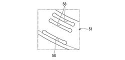
次に、図1、図6、図12、図13に基づいて、バスバーホルダ51について説明をする。図12は、図6のA部の拡大斜視図、図13は、図6のA部を裏側からみた平面図である。
図1、図6に示すように、バスバーホルダ51は、接続バスバーJを含む各相用バスバー30U,30V,30Wと、中性点用バスバー30Nとを収容可能なホルダ本体52を有している。
(Bus bar holder)
Next, the
As shown in FIGS. 1 and 6, the
ホルダ本体52は、樹脂等の絶縁部材により略リング状に形成されている。ホルダ本体52には、接続用バスバー30Jを含む各相用バスバー30U,30V,30W、及び中性点用バスバー30Nの各々バスバー本体31U,31V,31W,31J,31Nを、軸方向一方側から挿入可能な溝部53U,53V,53W,53J,53Nが形成されている。すなわち、各溝部53U,53V,53W,53J,53Nは、軸方向一方側が開口するように形成されている。
The holder
また、ホルダ本体52の外周縁には、各相用バスバー30U,30V,30Wの給電部39U,39V,39Wを載置可能な台座部55が径方向外側に向かって延出形成されている。台座部55は、軸方向平面視で周方向に長くなるように略長方形状に形成されている。そして、台座部55の長手方向、つまり、ホルダ本体52の周方向に沿って各給電部39U,39V,39WがU相、V相、W相の順に並列配置されている。
Further, on the outer peripheral edge of the holder
各溝部53U,53V,53W,53J,53Nは、各給電部39U,39V,39WがU相、V相、W相の順に並列配置されるように形成されている。すなわち、ホルダ本体52の最内周側に、接続用バスバー30Jのバスバー本体31Jを挿入可能な溝部53Jが6つ形成されている。また、この溝部53Jよりも径方向外側に、中性点用バスバー30Nのバスバー本体31Nを挿入可能な溝部53Nが形成されている。さらに、この溝部53Nよりも径方向外側に、V相用バスバー30Vのバスバー本体31Vを挿入可能な溝部53Vが形成されている。そして、この溝部53Vよりも径方向外側に、U相用バスバー30Uのバスバー本体31Uを挿入可能な溝部53Uと、W相用バスバー30Wのバスバー本体31Wを挿入可能な溝部53Wとが形成されている。
Each of the
ここで、図12、図13に詳示するように、各溝部53U,53V,53W,53J,53Nの開口縁の一部には、それぞれ各溝部53U,53V,53W,53J,53Nから各相用バスバー30U,30V,30W、接続用バスバー30J、及び中性点用バスバー30Nの抜けを防止するための抜け止め爪57a,57bが形成されている。
ホルダ本体52の抜け止め爪57a,57bが形成されている箇所の軸方向他方側には、不図示の金型の型抜き用の孔58が形成されている。この型抜き用の孔58を利用することにより、抜け止め爪57a,57bのアンダーカット部(不図示)を容易に形成することができる。これにより、ホルダ本体52の製造コストを低減できる。
Here, as shown in detail in FIGS. 12 and 13, a part of the opening edge of each of the
On the other side in the axial direction of the portion where the retaining
このように、ホルダ本体52に各溝部53U,53V,53W,53J,53Nを形成することにより、ホルダ本体52には径方向内側から順に、接続用バスバー30J、中性点用バスバー30N、V相用バスバー30Vが配置され、ホルダ本体52の最外周側に、U相用バスバー30U、及びW相用バスバー30Wが配置される。
Thus, by forming the
ここで、各相用バスバー30U,30V,30W、及び接続用バスバー30Jのバスバー本体31U,31V,31W,31Jを構成する第1本体131U,131V,131W,131J、及び第2本体231U,231V,231W,231Jの各曲率半径R1〜R8と、中性点用バスバー30Nのバスバー本体31Nの半径R9は、それぞれ式(1)〜式(6)を満たすように設定されている。
Here, the first
これにより、径方向における各バスバー本体31U〜31Nの隙間が最小限に抑えられている。とりわけ、図6に示すように、U相用バスバー30Uの第2本体231Uと、W相用バスバー30Wの第2本体231Wとが、先端に向かうに従って径方向内側に変位した状態になり、これら第2本体231U,231Wと、中性点用バスバー30Nのバスバー本体31Nとの間に、余分な隙間ができてしまうのが抑制される。
Thereby, the clearance gap between each bus-bar
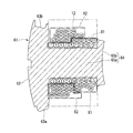
また、ホルダ本体52の内径E1は、ステータコア10に装着されているインシュレータ11の外周壁部11cの直径E2(図1参照)よりも大きく設定されている。これにより、図1に示すように、バスバーユニット50は、インシュレータ11よりも径方向外側に配置された状態で、且つインシュレータ11と軸方向でラップする位置に配置された状態になる。ステータコア10が圧入固定されているステータハウジング2の筒部2dには、バスバーユニット50に対応する位置に、バスバーユニット50を受け入れる拡径部92が段差により形成されている。
Further, the inner diameter E1 of the holder
この拡径部92にホルダ本体52の外周面が内嵌され、バスバーユニット50の径方向の位置決めが行われる。また、拡径部92の段差面92aにホルダ本体52が載置された形でバスバーユニット50の軸方向の位置決めが行われる。さらに、ホルダ本体52の外周面には、軸方向に沿って位置決め溝56が形成されている一方、ステータハウジング2の拡径部92には、位置決め溝56に臨まされる凸部(不図示)が形成されている。これにより、バスバーユニット50の周方向の位置決めが行われる。
The outer peripheral surface of the holder
ここで、インシュレータ11よりも径方向外側にバスバーユニット50が配置された状態で、ホルダ本体52から径方向内側に向かって各端子35U,35V,35W,35J,35Nが延出しているので、これら各端子35U,35V,35W,35J,35Nが各ティース部64のほぼ軸方向上方に位置した形になる。このため、各ティース部64から引き出されたコイル12の端末部の配索経路を単純化することができる。
このように構成されたバスバーユニット50によって、各相のコイル12は以下のように結線される。
Here, since the
By the
図14は、コイル12の結線図である。
すなわち、同図に示すように、バスバーユニット50の各相用バスバー30U,30V,30Wの各相端子35U,35V,35W、接続用バスバー30Jの接続端子35J、及び中性点用バスバー30Nの接続端子35Nに、それぞれ各相のコイル12の所定の端末部が接続されることにより、各相のコイル12は、所謂スター結線方式にて結線された状態になる。また、各ティース部64にコイル12を巻回するにあたって、それぞれのティース部64に2本のコイル12を巻回し、これら2本のコイル12の端末同士を結線する所謂ダブル巻が採用されている(図3、図5参照)。
FIG. 14 is a connection diagram of the
That is, as shown in the figure, each
具体的には、例えば、U相のコイル12は、コイル12Ua,12Ubが並列に接続される。また、コイル12Ua,12Ubと、コイル12Uc,12Udが、直列に接続される。さらに、コイル12Ua,12Ub、12Uc,12Udと、コイル12Ue,12Uf、12Ug,12Uhが、並列に接続される。このようにして、各相のコイル12は、それぞれ並列回路を構成している。
尚、V相のコイル12及びW相のコイル12もU相のコイル12と同様に構成されている。このため、V相のコイル12及びW相のコイル12についての記載は省略する。
Specifically, for example, the coils 12Ua and 12Ub of the
The V-
(ブラケット)
図1、図2に戻り、ステータハウジング2の開口部2aには、外フランジ部2eが形成されており、この外フランジ部2eに載置されるようにブラケット7が設けられている。
ブラケット7は、ステータハウジング2の開口部2aを閉塞するように略円板状に形成されている。ブラケット7の径方向中央には、回転シャフト6が挿通される挿通孔71が形成されている。この挿通孔71の内面側(ステータ3側の面、図1における右側の面)に、回転シャフト6を回転自在に支持するための軸受21が設けられている。一方、挿通孔71の外面側(図1における左側)には、挿通孔71と回転シャフト6との間のシール性を確保するためのシール部72が設けられている。
(bracket)
1 and 2, an
The
また、ブラケット7の外周部には、このブラケット7とステータハウジング2とを不図示のボルト等で締結固定するための複数(この実施形態では3つ)の貫通孔73が周方向に等間隔で形成されている。
Further, a plurality of (three in this embodiment) through
ここで、ステータハウジング2の外フランジ部2eには、ブラケット7の貫通孔73に対応する箇所に、径方向外側に向かって延出する舌片部18が形成されている。この舌片部18に、ブラケット7の貫通孔73に対応する貫通孔18aが形成されている。
舌片部18には、貫通孔18aの他に、電動自動二輪車の車体にブラシレスモータ1を固定するための取り付け孔18bが形成されていると共に、ステータハウジング2とブラケット7との位置決めを行うための位置決めピン(不図示)が挿入される孔18cが設けられている。
Here, the
In addition to the through
また、ステータハウジング2の外フランジ部2eには、バスバーユニット50の給電部39U,39V,39Wに対応する箇所に、軸方向平面視で略長方形状のグロメット受部19が周方向に長くなるように形成されている。このグロメット受部19は、ブラケット7と協働してバスバーユニット50の給電部39U,39V,39Wに取り付けられているグロメット54を挟持するためのものである。ブラケット7の外周部には、グロメット54を受け入れ可能なグロメット収納凹部74が形成されている。
Further, in the
グロメット54は、ステータハウジング2とブラケット7との間、及びこれらステータハウジング2やブラケット7と、バスバーユニット50の給電部39U,39V,39Wとの間のシール性を高めるためのものである。グロメット54は、例えば、ゴム等の弾性材によりステータハウジング2の周方向に沿って長くなるように、換言すれば、給電部39U,39V,39Wの配列方向に長くなるように、略直方体状に形成されている。そして、給電部39U,39V,39Wに対応する位置に、これら給電部39U,39V,39Wを挿通可能な挿通孔54aが形成されている。
The
また、グロメット54には、ステータハウジング2のグロメット受部19に当接する一側面54bに、長手方向に沿うガスケット溜り溝55aが形成されている。また、グロメット54の長手方向両端側には、ステータハウジング2の軸方向に沿うガスケット流通孔55bが形成されている。
各ガスケット流通孔55bは、ガスケット溜り溝55aと連通されている。これらガスケット溜り溝55a、及びガスケット流通孔55bは、ブラシレスモータ1の組み立て時に塗布される液状ガスケットGが充填される箇所である。
Further, the
Each
(ブラシレスモータの組み立て)
ここで、ブラシレスモータ1を組み立てるにあたって、ステータハウジング2の筒部2dにステータ3を圧入し、さらに、その上からグロメット54を装着した状態でバスバーユニット50をセットすると共にロータ4をセットし、最後にステータハウジング2の開口部2aを閉塞するようにブラケット7を組付ける。このブラケット7を組付ける際、このブラケット7とステータハウジング2との間のシール性を高めるために、液状ガスケットGが塗布される。
(Assembly of brushless motor)
Here, when assembling the brushless motor 1, the
すなわち、図2に詳示するように、ステータハウジング2にステータ3、ロータ4、及びバスバーユニット50を組付けた後であって、ブラケット7を組付ける前に、ステータハウジング2の外フランジ部2eと、ブラケット7の外周部との間に、液状ガスケットGが塗布される。また、グロメット54におけるグロメット受部19とは反対側の他側面54cに、液状ガスケットGが塗布される。
That is, as shown in detail in FIG. 2, after the
さらに、グロメット54に形成されているガスケット流通孔55bに液状ガスケットGを注入する。すると、液状ガスケットGが、ガスケット流通孔55bを通ってガスケット溜り溝55aに充填される。このため、ステータハウジング2にバスバーユニット50を組付けた後に液状ガスケットGを塗布する場合であっても、ステータハウジング2のグロメット受部19とグロメット54との間に、液状ガスケットGを容易に行き渡らせることができる。
このように、ステータハウジング2の外フランジ部2eに沿って液状ガスケットGを塗布した後、ステータハウジング2とブラケット7とを不図示のボルトによって締結固定することにより、ブラシレスモータ1の組み立てが完了する。
Further, the liquid gasket G is injected into the
Thus, after applying the liquid gasket G along the
(効果)
したがって、上述の実施形態によれば、バスバーユニット50のホルダ本体52の内径E1を、ステータコア10に装着されているインシュレータ11の外周壁部11cの直径E2よりも大きく設定することにより、ステータハウジング2内において、バスバーユニット50とインシュレータ11とを軸方向でラップする位置に配置することができる。
このため、この分、ステータコア10からバスバーユニット50までの高さH1(図1参照)を抑えることができる。この結果、ブラシレスモータ1の軸方向の長さを短くすることができ、ブラシレスモータ1の小型化を図ることができる。
(effect)
Therefore, according to the above-described embodiment, by setting the inner diameter E1 of the holder
For this reason, the height H1 (see FIG. 1) from the
また、インシュレータ11よりも径方向外側にバスバーユニット50が配置された状態で、ホルダ本体52から径方向内側に向かって各端子35U,35V,35W,35J,35Nが延出しているので、これら各端子35U,35V,35W,35J,35Nが各ティース部64のほぼ軸方向上方に位置した形になる。このため、各ティース部64から引き出されたコイル12の端末部の配索経路を単純化することができる。
Further, since the
さらに、インシュレータ11よりも径方向外側にバスバーユニット50が配置されていることから、各ティース部64の軸方向上方に空間を確保しやすく、コイル12で発生した熱の放熱効果を高めることができる。このため、ブラシレスモータ1の温度上昇を抑えることができ、ブラシレスモータ1のモータ効率を高めることが可能になる。
そして、ステータコア10から生じた熱がバスバーユニット50に伝達されにくくなるので、より確実にバスバーユニット50の温度上昇を抑えることができ、この結果、さらにブラシレスモータ1のモータ効率を高めることが可能になる。
Furthermore, since the
Since the heat generated from the
また、各相用バスバー30U,30V,30W、及び接続用バスバー30Jのバスバー本体31U,31V,31W,31Jを、それぞれ曲率半径の異なる第1本体131U,131V,131W,131Jと、第2本体231U,231V,231W,231Jとを連続形成することにより構成している。すなわち、第1本体131U,131V,131W,131J、及び第2本体231U,231V,231W,231Jの各曲率半径R1〜R8と、中性点用バスバー30Nのバスバー本体31Nの半径R9を、それぞれ式(1)〜式(6)を満たすように設定している。
Further, the
このため、径方向における各バスバー本体31U〜31Nの隙間が最小限に抑えることができる。とりわけ、U相用バスバー30Uの第2本体231U、及びW相用バスバー30Wの第2本体231Wと、中性点用バスバー30Nのバスバー本体31Nとの間に、余分な隙間ができてしまうのを防止できる。よって、バスバーユニット50の径方向を縮径化でき、この結果、ブラシレスモータ1を小型化することが可能になる。
For this reason, the clearance gap between each bus-bar
ここで、各相用バスバー30U,30V,30W、及び接続用バスバー30Jのバスバー本体31U,31V,31W,31Jの延在方向の途中に屈曲部を形成することにより、各バスバー30U,30V,30W,30Jの径を変化させ、バスバーユニット50の径方向を縮径化することも考えられる。しかしながら、屈曲部を形成せずに連続的に各バスバー本体31U,31V,31W,31Jの曲率半径を変化させることにより、各相用バスバー30U,30V,30W、及び接続用バスバー30Jを形成するのが容易になり、製造コストを抑えることができる。
Here, each
さらに、接続用バスバー30Jを含む各相用バスバー30U,30V,30W、及び中性点用バスバー30Nを一体化するために、各溝部53U,53V,53W,53J,53Nが形成されたホルダ本体52を用いている。そして、ホルダ本体52の各溝部53U,53V,53W,53J,53Nの開口縁の一部に、それぞれ抜け止め爪57a,57bを形成することにより、ホルダ本体52からの接続用バスバー30Jを含む各相用バスバー30U,30V,30W、及び中性点用バスバー30Nの抜けを確実に防止できる。このように、接続用バスバー30Jを含む各相用バスバー30U,30V,30W、及び中性点用バスバー30Nを一体化するために、これらを樹脂モールド体によってモールドする必要がないので、モールドするための大掛かりな設備が必要なくなる。バスバーユニット50を製造するための設備を従来よりも簡素化でき、バスバーユニット50の製造コストを低減できる。
Further, in order to integrate each
また、抜け止め爪57a,57bを形成して抜け止めとしていることから、接続用バスバー30Jを含む各相用バスバー30U,30V,30W、及び中性点用バスバー30Nと、各溝部53U,53V,53W,53J,53Nの寸法公差を高精度に管理する必要がない。このため、各バスバー30U,30V,30W,30J,30N、及びホルダ本体52を容易に製造することができ、製造コストを低減できる。
そして、各バスバー本体31U,31V,31W,31Jの形状を、各溝部53U,53V,53W,53Jの形状と異なる形状とし、各バスバー本体31U,31V,31W,31Jの弾性で保持する場合に対し、確実に各バスバー本体31U,31V,31W,31Jを保持することが可能になる。
Further, since the retaining
And the shape of each bus-bar
また、ホルダ本体52の抜け止め爪57a,57bが形成されている箇所の軸方向他方側に、不図示の金型の型抜き用の孔58を形成している。この型抜き用の孔58を利用することにより、抜け止め爪57a,57bのアンダーカット部(不図示)を容易に形成することができる。これにより、不図示の金型の構造を簡素化でき、この結果、ホルダ本体52の製造コストを低減できる。
In addition, a die-cutting hole 58 (not shown) is formed on the other side in the axial direction of the portion of the
さらに、各ティース部64にコイル12を巻回するにあたって、それぞれのティース部64に2本のコイル12を巻回し、これら2本のコイル12の端末同士を結線する所謂ダブル巻を採用している。これにより、各相のコイル12がそれぞれ並列回路を成しているので、コイル12の線径を細径化しながら各ティース部64に巻回されるコイル12の総抵抗を抑制することができる。このため、コイル12を細径化できる分、巻回作業を容易にすることができると共に、太径のコイルと比較してデッドスペースを減少させることができ、占積率を向上させることができる。
Further, when the
そして、各ティース部64にコイル12を巻回するにあたって、ティース部64への巻回途中(本実施形態では28回目と29回目との間)に、コイル12にループ部12aを形成し、後にこのループ部12aを切断することにより、ティース部64に1本のコイル12を連続して巻回しながら、ダブル巻としている。
このため、通常のダブル巻と比較して巻回作業の時間を短縮することができる。また、コイル12を巻装するための装置のコストを低減することができる。すなわち、例えば、ダブル巻を行う場合、2本のノズルを用いて2本のコイルを同時にティース部64に巻装するための設備が必要となる場合がある。しかしながら、本実施形態では、1本のノズルを用い、この1本のノズルを操作するだけでダブル巻とすることができる。よって、コイル12を巻装するための装置のコストを確実に低減することができる。
And when winding the
For this reason, the time of winding work can be shortened compared with normal double winding. Moreover, the cost of the apparatus for winding the
また、バスバーユニット50の給電部39U,39V,39Wに装着されるグロメット54の一側面54bにガスケット溜り溝55aを形成すると共に、グロメット54の長手方向両端側に、ガスケット流通孔55bが形成されている。このため、ステータハウジング2にバスバーユニット50を組付けた後に液状ガスケットGを塗布する場合であっても、ステータハウジング2のグロメット受部19とグロメット54との間に、液状ガスケットGを容易に行き渡らせることができる。よって、ステータハウジング2とブラケット7との間のシール性を確実に高めることができる。
In addition, a
尚、本発明は上述の実施形態に限られるものではなく、本発明の趣旨を逸脱しない範囲において、上述の実施形態に種々の変更を加えたものを含む。
例えば、上述の実施形態では、ブラシレスモータ1は、電動自動二輪車に用いられるものである場合について説明した。しかしながら、これに限られるものではなく、バスバーユニット50を備えた種々の電動モータに本実施形態のブラシレスモータ1の構造を適用することが可能である。
また、上述の実施形態では、各ティース部64へのコイル12の巻回数を28回とした場合について説明した。しかしながら、ティース部64への巻回数は、28回に限られるものではなく、所望のモータ特性を得るために適宜巻回数を変更することが可能である。
The present invention is not limited to the above-described embodiment, and includes various modifications made to the above-described embodiment without departing from the spirit of the present invention.
For example, in the above-described embodiment, the case where the brushless motor 1 is used for an electric motorcycle has been described. However, the present invention is not limited to this, and the structure of the brushless motor 1 of this embodiment can be applied to various electric motors including the
Moreover, in the above-mentioned embodiment, the case where the winding number of the
さらに、上述の実施形態では、バスバーユニット50は、各相のコイル12の一方の端末部と接続される各相用バスバー(U相用バスバー30U、V相用バスバー30V、W相用バスバー30W)と、各相のコイル12の他方の端末部と接続される中性点用バスバー30Nとを有し、この中性点用バスバー30Nにより、各相のコイル12を所謂スター結線方式にて結線している場合について説明した。しかしながら、これに限られるものではなく、中性点を有さない、所謂デルタ結線方式についても、本発明の構成を適用することができる。この場合、バスバーユニット50は、中性点用バスバー30Nを有さない構成となる。
Furthermore, in the above-described embodiment, the
そして、上述の実施形態では、グロメット54は、例えば、ゴム等の弾性材により形成されている場合について説明した。しかしながら、これに限られるものではなく、ステータハウジング2とブラケット7との間のシール性を確保できる材料により形成されていればよい。例えば、ゴムに代わって樹脂材によりグロメット54を形成してもよい。
And in the above-mentioned embodiment, the case where the
また、上述の実施形態では、バスバーユニット50の給電部39U,39V,39Wに取り付けられているグロメット54には、ステータハウジング2のグロメット受部19に当接する一側面54bに、長手方向に沿うガスケット溜り溝55aを形成し、ステータハウジング2のグロメット受部19とグロメット54との間のシール性を高めている場合について説明した。しかしながら、これに限られるものではなく、グロメット54に、以下のようなガスケット溜り溝155aを形成してもよい。
In the above-described embodiment, the
(変形例)
図15は、本実施形態の変形例におけるグロメット154の平面図である。尚、図15において、上述の実施形態と同一態様には同一符号を付して説明を省略する。
同図に示すように、グロメット54の長手方向両端側には、ステータハウジング2の軸方向に沿うガスケット流通孔55bが形成されている。また、グロメット54の長手方向両端側には、ステータハウジング2のグロメット受部19に当接する一側面54bに、軸方向平面視で略L字状のガスケット溜り溝155が2つ形成されている。
(Modification)
FIG. 15 is a plan view of a grommet 154 in a modification of the present embodiment. In FIG. 15, the same reference numerals are given to the same aspects as those in the above-described embodiment, and the description thereof is omitted.
As shown in the figure, gasket circulation holes 55 b are formed along the axial direction of the
ガスケット溜り溝155について詳述すると、各ガスケット溜り溝155は、それぞれガスケット流通孔55bと連通されている。ガスケット溜り溝155は、ガスケット流通孔55bから給電部39U,39V,39Wの延在方向に沿うように径方向外側に向かって延出する第1溝部155aと、ガスケット流通孔55bからステータハウジング2の周方向に沿うように外側に向かって延出する第2溝部155bとを有している。そして、これら第1溝部155aと第2溝部155bとが連通形成され、軸方向平面視で略L字状になっている。このようにグロメット54にガスケット溜り溝155を形成した場合であっても、前述の実施形態と同様の効果を奏することができる。
The
1 ブラシレスモータ
4 ロータ
10 ステータコア
11 インシュレータ
12 コイル
12a ループ部
30J 接続用バスバー(相用バスバー)
30N 中性点用バスバー
30U U相用バスバー(第1相用バスバー)
30V V相用バスバー(第2相用バスバー)
30W W相用バスバー(第3相用バスバー)
31J,31N,31U,31V,31W バスバー本体
35J 接続端子(相端子)
35N 中性点端子
35U U相端子(相端子)
35V V相端子(相端子)
35W W相端子(相端子)
39U 給電部
39V 給電部
39W 給電部
50 バスバーユニット
51 バスバーホルダ
52 ホルダ本体
53J,53N,53U,53V,53W 溝部(溝)
54 グロメット
54b 一側面(他方の平面)
55a ガスケット溜り溝
55b ガスケット流通孔
57a,57b 抜け止め爪
64 ティース部(ティース)
E1 内径
E2 直径
G 液状ガスケット(液状シール材)
R1〜R9 曲率半径
DESCRIPTION OF SYMBOLS 1
30N Neutral
30V V-phase bus bar ( second- phase bus bar)
30W W-phase bus bar ( third- phase bus bar)
31J, 31N, 31U, 31V,
35N
35V V-phase terminal (phase terminal)
35W W phase terminal (phase terminal)
39U power supply unit
39V feeding section
39W
54
55a
E1 Inner diameter E2 Diameter G Liquid gasket (liquid sealing material)
R1-R9 radius of curvature
Claims (5)
このステータコアの径方向内側に配置され、前記ステータコアに対して回転自在に支持されているロータと、
前記ステータコアにインシュレータを介して巻回された複数の相のコイルに、給電を行うためのリング状のバスバーユニットとを備えたブラシレスモータであって、
前記バスバーユニットは、
それぞれ前記コイルの一端と接続される2つの相端子を有すると共に、外部電源と電気的に接続される給電部を有する湾曲状の第1相用バスバー、第2相用バスバー、および第3相用バスバーと、
前記第1相用バスバー、前記第2相用バスバー、および前記第3相用バスバーのそれぞれを保持する絶縁部材からなるリング状のバスバーホルダとを備え、
前記バスバーホルダの内周面の直径を、前記インシュレータの外周面の直径よりも大きく設定し、前記インシュレータよりも径方向外側に、前記バスバーユニットを配置し、
前記第1相用バスバー、前記第2相用バスバー、および前記第3相用バスバーのそれぞれは、帯状の金属板の厚さ方向を湾曲形成して成ると共に、
前記第1相用バスバー、および前記第3相用バスバーは、それぞれの両端側に前記相端子が設けられており、且つ2つの前記相端子の一方の相端子よりも端部側に前記給電部が設けられており、
前記第2相用バスバーは、両端側に前記相端子が設けられており、且つ2つの前記相端子の間に前記給電部が設けられており、
前記第1相用バスバー、前記第2相用バスバー、および前記第3相用バスバーは、前記第2相用バスバーが間に位置するように、それぞれ径方向に並んで配置され、
前記第1相用バスバー、および前記第3相用バスバーの少なくとも何れか一方は、2つの前記相端子の間で、且つ周方向の途中から曲率半径が変化するように連続的に形成されていることを特徴とするブラシレスモータ。 A stator core;
A rotor that is disposed radially inside the stator core and is rotatably supported with respect to the stator core;
A brushless motor comprising a ring-shaped bus bar unit for supplying power to a plurality of phase coils wound around the stator core via an insulator,
The bus bar unit is
Together with two phases terminal connected to one end of the previous SL coils respectively, the first phase bus bar curved with a feeding part connected to an external power source and electrically, for the second phase busbar, and the third phase For bus bar ,
A ring-shaped bus bar holder made of an insulating member that holds each of the first phase bus bar, the second phase bus bar, and the third phase bus bar;
The diameter of the inner peripheral surface of the bus bar holder is set larger than the diameter of the outer peripheral surface of the insulator, and the bus bar unit is disposed radially outside the insulator,
Said first phase bus bar, the second phase bus bar, and each of the third phase busbar is a thickness direction of the strip-shaped metal plate is curved formed Rutotomoni,
The first-phase bus bar and the third-phase bus bar are provided with the phase terminals on both end sides thereof, and the power feeding section on the end side of one of the two phase terminals. Is provided,
The second phase bus bar is provided with the phase terminals on both end sides, and the power feeding portion is provided between the two phase terminals.
The first-phase bus bar, the second-phase bus bar, and the third-phase bus bar are arranged side by side in the radial direction so that the second-phase bus bar is located between them ,
At least one of the first-phase bus bar and the third-phase bus bar is continuously formed between the two phase terminals so that the radius of curvature changes from the middle in the circumferential direction. A brushless motor characterized by that.
前記ステータハウジングには、前記バスバーユニットに対応する位置に、前記バスバーユニットを受け入れる拡径部が段差によって形成されていることを特徴とする請求項1に記載のブラシレスモータ。 The stator core is press-fitted into a stator housing;
2. The brushless motor according to claim 1, wherein the stator housing is formed with a stepped portion at a position corresponding to the bus bar unit.
各溝の開口縁の少なくとも一部に、前記第1相用バスバー、前記第2相用バスバー、および前記第3相用バスバーの抜けを防止するための抜け止め爪が形成されていることを特徴とする請求項1又は請求項2に記載のブラシレスモータ。 The bus bar holder has a holder body formed in a ring shape, and the first phase bus bar, the second phase bus bar, and the third phase bus bar are inserted into the holder body from one side in the axial direction. A plurality of possible grooves are formed side by side in the radial direction,
A retaining claw for preventing the first- phase bus bar, the second-phase bus bar, and the third-phase bus bar from coming off is formed on at least a part of the opening edge of each groove. The brushless motor according to claim 1 or 2.
前記グロメットは、
前記グロメットの一方の平面から形成され、液状シール材を注入するためのガスケット流通孔と、
前記グロメットの他方の平面の全域に渡って形成され、前記ガスケット流通孔に連通するガスケット溜り溝とを備えていることを特徴とする請求項1〜請求項4の何れか1項に記載のブラシレスモータ。 The bus bar unit includes a grommet,
The grommet is
A gasket circulation hole for injecting a liquid sealing material formed from one plane of the grommet,
The brushless according to any one of claims 1 to 4, further comprising a gasket reservoir groove formed over the entire other plane of the grommet and communicating with the gasket circulation hole. motor.
Priority Applications (3)
| Application Number | Priority Date | Filing Date | Title |
|---|---|---|---|
| JP2012092148A JP5818737B2 (en) | 2012-04-13 | 2012-04-13 | Brushless motor |
| CN201380017893.4A CN104205579B8 (en) | 2012-04-13 | 2013-04-05 | Brushless motor |
| PCT/JP2013/060522 WO2013154054A1 (en) | 2012-04-13 | 2013-04-05 | Brushless motor |
Applications Claiming Priority (1)
| Application Number | Priority Date | Filing Date | Title |
|---|---|---|---|
| JP2012092148A JP5818737B2 (en) | 2012-04-13 | 2012-04-13 | Brushless motor |
Publications (3)
| Publication Number | Publication Date |
|---|---|
| JP2013223293A JP2013223293A (en) | 2013-10-28 |
| JP2013223293A5 JP2013223293A5 (en) | 2014-03-27 |
| JP5818737B2 true JP5818737B2 (en) | 2015-11-18 |
Family
ID=49327619
Family Applications (1)
| Application Number | Title | Priority Date | Filing Date |
|---|---|---|---|
| JP2012092148A Expired - Fee Related JP5818737B2 (en) | 2012-04-13 | 2012-04-13 | Brushless motor |
Country Status (3)
| Country | Link |
|---|---|
| JP (1) | JP5818737B2 (en) |
| CN (1) | CN104205579B8 (en) |
| WO (1) | WO2013154054A1 (en) |
Families Citing this family (7)
| Publication number | Priority date | Publication date | Assignee | Title |
|---|---|---|---|---|
| FR3018964B1 (en) * | 2014-03-24 | 2016-03-04 | Valeo Equip Electr Moteur | INTERCONNECTION ELEMENT FOR CONNECTING STATOR COILS |
| JP6287784B2 (en) * | 2014-11-28 | 2018-03-07 | 日本電産株式会社 | motor |
| EP3072943B1 (en) | 2015-03-26 | 2018-05-02 | Idemitsu Kosan Co., Ltd. | Dibenzofuran/carbazole-substituted benzonitriles |
| DE102015209041A1 (en) * | 2015-05-18 | 2016-11-24 | Robert Bosch Gmbh | Stator for an electric machine, and method of making such a |
| DE102017106399B4 (en) | 2017-03-24 | 2023-10-05 | Nidec Corporation | Electric motor |
| JP2020043734A (en) * | 2018-09-13 | 2020-03-19 | 本田技研工業株式会社 | Stator core for rotary electric machine and rotary electric machine |
| KR20200087474A (en) * | 2019-01-11 | 2020-07-21 | 엘지이노텍 주식회사 | Motor |
Family Cites Families (11)
| Publication number | Priority date | Publication date | Assignee | Title |
|---|---|---|---|---|
| JP5217117B2 (en) * | 2006-06-05 | 2013-06-19 | 日本電産株式会社 | Brushless motor |
| JP2008035616A (en) * | 2006-07-28 | 2008-02-14 | Aisin Seiki Co Ltd | Motor |
| JP4939244B2 (en) * | 2007-01-31 | 2012-05-23 | アイチエレック株式会社 | Winding connection device for rotating machine, stator for rotating machine and rotating machine |
| JP4617342B2 (en) * | 2007-10-29 | 2011-01-26 | 三菱電機株式会社 | Starter |
| JP4546546B2 (en) * | 2008-01-10 | 2010-09-15 | ホーチキ株式会社 | Series unit |
| WO2009113633A1 (en) * | 2008-03-13 | 2009-09-17 | 日本電産株式会社 | Bus bar terminal, bus bar unit, and motor |
| JP2009261220A (en) * | 2008-03-19 | 2009-11-05 | Toyota Motor Corp | Method of manufacturing stator |
| JP5334441B2 (en) * | 2008-03-28 | 2013-11-06 | 三洋電機株式会社 | Electric motor |
| JP2010028914A (en) * | 2008-07-16 | 2010-02-04 | Sumitomo Electric Ind Ltd | Resin molded coil, resin molded stators, and manufacturing method for the stators |
| JP4924595B2 (en) * | 2008-12-09 | 2012-04-25 | 日産自動車株式会社 | Concentrated power distribution member for concentrated winding motor |
| JP5321983B2 (en) * | 2010-07-20 | 2013-10-23 | 株式会社安川電機 | Stator, rotating electric machine, and winding method |
-
2012
- 2012-04-13 JP JP2012092148A patent/JP5818737B2/en not_active Expired - Fee Related
-
2013
- 2013-04-05 CN CN201380017893.4A patent/CN104205579B8/en not_active Expired - Fee Related
- 2013-04-05 WO PCT/JP2013/060522 patent/WO2013154054A1/en active Application Filing
Also Published As
| Publication number | Publication date |
|---|---|
| CN104205579B8 (en) | 2017-04-12 |
| JP2013223293A (en) | 2013-10-28 |
| WO2013154054A1 (en) | 2013-10-17 |
| CN104205579B (en) | 2016-11-09 |
| CN104205579A (en) | 2014-12-10 |
Similar Documents
| Publication | Publication Date | Title |
|---|---|---|
| JP5818737B2 (en) | Brushless motor | |
| JP4404199B2 (en) | Synchronous motor | |
| JP6068953B2 (en) | Electric motor | |
| JP6135982B2 (en) | motor | |
| EP3176912B1 (en) | Stator and rotating machine | |
| JP6371947B2 (en) | motor | |
| JP2010141953A (en) | Concentrated power distribution member for concentratedly-wound motors | |
| JP6706583B2 (en) | Brushless motor | |
| US10840656B2 (en) | Bus bar unit and rotary electric machine having the same | |
| JP5612405B2 (en) | Brushless motor | |
| JP2009225572A (en) | Stator and brushless motor | |
| JP5839627B2 (en) | Brushless motor | |
| JP2016019420A (en) | Bus bar unit and rotary electric machine including the same | |
| JP5998871B2 (en) | Rotating electric machine stator | |
| JP2011045202A (en) | Armature for rotary electric machine and insulating member | |
| WO2016059944A1 (en) | Stator | |
| JP6485486B2 (en) | Three-phase motor | |
| CN211930351U (en) | Stator and brushless motor | |
| JP2019103354A (en) | Rotary electric machine | |
| JP5111887B2 (en) | Rotating electric machine stator | |
| JP2012196043A (en) | Method for winding coil of dc motor and dc motor | |
| JP2012244839A (en) | Stator for rotating electric machine | |
| JP2010063233A (en) | Rotating electrical machine | |
| JP2003169458A (en) | Wiring structure for equalizing wire in rotating electric machine | |
| JP6399144B2 (en) | motor |
Legal Events
| Date | Code | Title | Description |
|---|---|---|---|
| A521 | Written amendment |
Free format text: JAPANESE INTERMEDIATE CODE: A523 Effective date: 20140206 |
|
| A621 | Written request for application examination |
Free format text: JAPANESE INTERMEDIATE CODE: A621 Effective date: 20140206 |
|
| A131 | Notification of reasons for refusal |
Free format text: JAPANESE INTERMEDIATE CODE: A131 Effective date: 20150106 |
|
| A521 | Written amendment |
Free format text: JAPANESE INTERMEDIATE CODE: A523 Effective date: 20150309 |
|
| TRDD | Decision of grant or rejection written | ||
| A01 | Written decision to grant a patent or to grant a registration (utility model) |
Free format text: JAPANESE INTERMEDIATE CODE: A01 Effective date: 20150924 |
|
| A61 | First payment of annual fees (during grant procedure) |
Free format text: JAPANESE INTERMEDIATE CODE: A61 Effective date: 20150929 |
|
| R150 | Certificate of patent or registration of utility model |
Ref document number: 5818737 Country of ref document: JP Free format text: JAPANESE INTERMEDIATE CODE: R150 |
|
| LAPS | Cancellation because of no payment of annual fees |