JP5812952B2 - Exhaust gas purification system for internal combustion engine - Google Patents
Exhaust gas purification system for internal combustion engine Download PDFInfo
- Publication number
- JP5812952B2 JP5812952B2 JP2012179375A JP2012179375A JP5812952B2 JP 5812952 B2 JP5812952 B2 JP 5812952B2 JP 2012179375 A JP2012179375 A JP 2012179375A JP 2012179375 A JP2012179375 A JP 2012179375A JP 5812952 B2 JP5812952 B2 JP 5812952B2
- Authority
- JP
- Japan
- Prior art keywords
- stoichiometric
- air
- ammonia
- exhaust
- sensor
- Prior art date
- Legal status (The legal status is an assumption and is not a legal conclusion. Google has not performed a legal analysis and makes no representation as to the accuracy of the status listed.)
- Expired - Fee Related
Links
- 238000000746 purification Methods 0.000 title claims description 72
- 238000002485 combustion reaction Methods 0.000 title claims description 29
- QGZKDVFQNNGYKY-UHFFFAOYSA-N Ammonia Chemical compound N QGZKDVFQNNGYKY-UHFFFAOYSA-N 0.000 claims description 204
- 239000000446 fuel Substances 0.000 claims description 180
- 239000003054 catalyst Substances 0.000 claims description 148
- 238000001514 detection method Methods 0.000 claims description 139
- 229910021529 ammonia Inorganic materials 0.000 claims description 95
- 239000001301 oxygen Substances 0.000 claims description 95
- 229910052760 oxygen Inorganic materials 0.000 claims description 95
- 239000007789 gas Substances 0.000 claims description 86
- QVGXLLKOCUKJST-UHFFFAOYSA-N atomic oxygen Chemical compound [O] QVGXLLKOCUKJST-UHFFFAOYSA-N 0.000 claims description 82
- 230000009467 reduction Effects 0.000 claims description 65
- 239000003638 chemical reducing agent Substances 0.000 claims description 49
- 238000011144 upstream manufacturing Methods 0.000 claims description 44
- 239000000203 mixture Substances 0.000 claims description 35
- 230000006866 deterioration Effects 0.000 claims description 27
- 239000000463 material Substances 0.000 claims description 27
- 239000007784 solid electrolyte Substances 0.000 claims description 24
- 230000001276 controlling effect Effects 0.000 claims description 17
- MWUXSHHQAYIFBG-UHFFFAOYSA-N nitrogen oxide Inorganic materials O=[N] MWUXSHHQAYIFBG-UHFFFAOYSA-N 0.000 claims description 12
- 238000004364 calculation method Methods 0.000 claims description 11
- 230000000694 effects Effects 0.000 claims description 9
- 239000002243 precursor Substances 0.000 claims description 9
- 230000007423 decrease Effects 0.000 claims description 7
- 230000002596 correlated effect Effects 0.000 claims description 6
- 238000005259 measurement Methods 0.000 claims description 2
- 238000006722 reduction reaction Methods 0.000 description 56
- 230000003197 catalytic effect Effects 0.000 description 53
- 238000000034 method Methods 0.000 description 48
- WTHDKMILWLGDKL-UHFFFAOYSA-N urea;hydrate Chemical compound O.NC(N)=O WTHDKMILWLGDKL-UHFFFAOYSA-N 0.000 description 46
- 230000008569 process Effects 0.000 description 35
- 238000002347 injection Methods 0.000 description 34
- 239000007924 injection Substances 0.000 description 34
- 238000006243 chemical reaction Methods 0.000 description 23
- 238000007254 oxidation reaction Methods 0.000 description 16
- 230000003647 oxidation Effects 0.000 description 14
- 230000008929 regeneration Effects 0.000 description 13
- 238000011069 regeneration method Methods 0.000 description 13
- -1 oxygen ion Chemical class 0.000 description 11
- 238000010586 diagram Methods 0.000 description 8
- 230000008859 change Effects 0.000 description 7
- 229910000069 nitrogen hydride Inorganic materials 0.000 description 7
- BASFCYQUMIYNBI-UHFFFAOYSA-N platinum Chemical compound [Pt] BASFCYQUMIYNBI-UHFFFAOYSA-N 0.000 description 6
- 238000009825 accumulation Methods 0.000 description 5
- 238000012545 processing Methods 0.000 description 5
- XSQUKJJJFZCRTK-UHFFFAOYSA-N Urea Chemical compound NC(N)=O XSQUKJJJFZCRTK-UHFFFAOYSA-N 0.000 description 4
- MCMNRKCIXSYSNV-UHFFFAOYSA-N Zirconium dioxide Chemical compound O=[Zr]=O MCMNRKCIXSYSNV-UHFFFAOYSA-N 0.000 description 4
- 239000004202 carbamide Substances 0.000 description 4
- 230000003247 decreasing effect Effects 0.000 description 4
- 230000001133 acceleration Effects 0.000 description 3
- 239000002253 acid Substances 0.000 description 3
- 230000000875 corresponding effect Effects 0.000 description 3
- 230000001590 oxidative effect Effects 0.000 description 3
- 230000004044 response Effects 0.000 description 3
- 239000004020 conductor Substances 0.000 description 2
- 230000001419 dependent effect Effects 0.000 description 2
- SIWVEOZUMHYXCS-UHFFFAOYSA-N oxo(oxoyttriooxy)yttrium Chemical compound O=[Y]O[Y]=O SIWVEOZUMHYXCS-UHFFFAOYSA-N 0.000 description 2
- 239000013618 particulate matter Substances 0.000 description 2
- 229910052697 platinum Inorganic materials 0.000 description 2
- 230000027756 respiratory electron transport chain Effects 0.000 description 2
- 239000000243 solution Substances 0.000 description 2
- 230000002269 spontaneous effect Effects 0.000 description 2
- 230000015556 catabolic process Effects 0.000 description 1
- 229910000420 cerium oxide Inorganic materials 0.000 description 1
- 150000001875 compounds Chemical class 0.000 description 1
- 239000002772 conduction electron Substances 0.000 description 1
- 238000006731 degradation reaction Methods 0.000 description 1
- 239000003792 electrolyte Substances 0.000 description 1
- 238000002474 experimental method Methods 0.000 description 1
- 238000010438 heat treatment Methods 0.000 description 1
- 230000007062 hydrolysis Effects 0.000 description 1
- 230000010354 integration Effects 0.000 description 1
- 230000002452 interceptive effect Effects 0.000 description 1
- BMMGVYCKOGBVEV-UHFFFAOYSA-N oxo(oxoceriooxy)cerium Chemical compound [Ce]=O.O=[Ce]=O BMMGVYCKOGBVEV-UHFFFAOYSA-N 0.000 description 1
- 150000002926 oxygen Chemical class 0.000 description 1
- 231100000572 poisoning Toxicity 0.000 description 1
- 230000000607 poisoning effect Effects 0.000 description 1
- 230000001737 promoting effect Effects 0.000 description 1
- 230000000630 rising effect Effects 0.000 description 1
- 239000004071 soot Substances 0.000 description 1
- 238000005979 thermal decomposition reaction Methods 0.000 description 1
- 238000009283 thermal hydrolysis Methods 0.000 description 1
- 230000001052 transient effect Effects 0.000 description 1
- 230000007704 transition Effects 0.000 description 1
Images


Classifications
-
- Y—GENERAL TAGGING OF NEW TECHNOLOGICAL DEVELOPMENTS; GENERAL TAGGING OF CROSS-SECTIONAL TECHNOLOGIES SPANNING OVER SEVERAL SECTIONS OF THE IPC; TECHNICAL SUBJECTS COVERED BY FORMER USPC CROSS-REFERENCE ART COLLECTIONS [XRACs] AND DIGESTS
- Y02—TECHNOLOGIES OR APPLICATIONS FOR MITIGATION OR ADAPTATION AGAINST CLIMATE CHANGE
- Y02T—CLIMATE CHANGE MITIGATION TECHNOLOGIES RELATED TO TRANSPORTATION
- Y02T10/00—Road transport of goods or passengers
- Y02T10/10—Internal combustion engine [ICE] based vehicles
- Y02T10/12—Improving ICE efficiencies
Landscapes
- Measuring Oxygen Concentration In Cells (AREA)
- Exhaust-Gas Circulating Devices (AREA)
- Exhaust Gas After Treatment (AREA)
- Combined Controls Of Internal Combustion Engines (AREA)
- Exhaust Gas Treatment By Means Of Catalyst (AREA)
Description
本発明は、内燃機関の排気浄化システムに関する。より詳しくは、選択還元触媒とその下流に設けられたNH3センサとを備えた内燃機関の排気浄化システムに関する。 The present invention relates to an exhaust gas purification system for an internal combustion engine. More specifically, the present invention relates to an exhaust gas purification system for an internal combustion engine provided with a selective reduction catalyst and an NH 3 sensor provided downstream thereof.
従来、排気中のNOxを浄化する排気浄化システムの1つとして、アンモニア(NH3)などの還元剤により排気中のNOxを選択的に還元する選択還元触媒を排気通路に設けたものが提案されている(例えば、特許文献1参照)。例えば、尿素添加式の排気浄化システムでは、選択還元触媒の上流側からNH3の前駆体である尿素水を供給し、この尿素水から排気の熱で熱分解又は加水分解することでNH3を生成し、このNH3により排気中のNOxを選択的に還元する。このような尿素添加式のシステムの他、例えば、アンモニアカーバイトのようなNH3の化合物を加熱することでNH3を生成し、このNH3を直接添加するシステムも提案されている。 Conventionally, as one of exhaust purification systems for purifying NOx in exhaust, a system in which a selective reduction catalyst for selectively reducing NOx in exhaust with a reducing agent such as ammonia (NH 3 ) is provided in the exhaust passage has been proposed. (For example, refer to Patent Document 1). For example, in the exhaust purification system of urea addition type, the NH 3 by supplying urea water which is a precursor of NH 3 from the upstream side of the selective reduction catalyst, thermal decomposition or hydrolysis in the exhaust heat from the urea water The NOx in the exhaust gas is selectively reduced by this NH 3 . In addition to such a urea addition type system, for example, a system in which NH 3 is generated by heating a NH 3 compound such as ammonia carbide and this NH 3 is directly added has also been proposed.
選択還元触媒は、混合気の空燃比をストイキよりリーン側にし酸素を多く含んだリーン空燃比の排気下で高いNOx浄化性能を発揮するため、リーン燃焼式のガソリンエンジンやディーゼルエンジンなど、リーン燃焼を基本とした機関の排気浄化システムに用いられる場合が多い。またこの場合、選択還元触媒の下流側に設けられたNH3センサの検出信号に基づくフィードバック制御によって選択還元触媒に供給する尿素水又はNH3の供給量を制御することにより、選択還元触媒からのNH3スリップ量を最小限に留めながらそのNOx浄化率を高く維持できることも知られている(例えば、特許文献1参照)。 Selective reduction catalysts have a lean air-fuel ratio that is leaner than stoichiometric and exhibits high NOx purification performance under lean air-fuel ratio exhaust gas that contains a large amount of oxygen. Therefore, lean combustion such as lean-burn gasoline engines and diesel engines Often used in engine exhaust purification systems based on Further, in this case, by controlling the supply amount of urea water or NH 3 supplied to the selective reduction catalyst by feedback control based on the detection signal of the NH 3 sensor provided on the downstream side of the selective reduction catalyst, It is also known that the NOx purification rate can be maintained high while minimizing the NH 3 slip amount (see, for example, Patent Document 1).
しかしながら、NOx排出量が多くなる加速運転時には、選択還元触媒のみでは十分にNOxを浄化しきれなくなる場合がある。そこで、特許文献2に開示されているシステムのように、加速運転時には選択還元触媒の上流側に設けられた三元触媒における三元浄化反応を利用してNOxを浄化することが考えられる。特許文献2の排気浄化システムでは、NOx吸蔵還元型触媒の上流側に三元触媒を設けたシステムにおいて、加速運転時には三元触媒における三元浄化反応を利用すべく、混合気の空燃比をリーン側からストイキに切り替える。
However, during acceleration operation in which the amount of NOx emissions increases, NOx may not be sufficiently purified with only the selective reduction catalyst. Therefore, as in the system disclosed in
ところが、三元触媒における三元浄化反応を高い効率で発揮しようとすると、混合気の空燃比を精度良くストイキ又はその近傍に維持しなければならないが、このような空燃比制御を行うには排気の酸素濃度を直接的に検出する酸素濃度センサからのフィードバックがさらに必要となる。また、このような三元触媒を備えないシステムであっても、排気中のスートを捕集する排気浄化フィルタの再生時や選択還元触媒のSOx被毒再生時などにおいても、混合気の空燃比をストイキ又はストイキよりリッチ側へリッチ化するために酸素濃度センサが必要となる。 However, if the three-way purification reaction in the three-way catalyst is to be performed with high efficiency, the air-fuel ratio of the air-fuel mixture must be accurately maintained at or near the stoichiometry. Further feedback from an oxygen concentration sensor that directly detects the oxygen concentration of the gas is required. Even in a system that does not include such a three-way catalyst, the air-fuel ratio of the air-fuel mixture can also be used during regeneration of an exhaust purification filter that collects soot in exhaust gas or during SOx poisoning regeneration of a selective reduction catalyst. In order to enrich the stoichiometry or the richer side than the stoichiometry, an oxygen concentration sensor is required.
本発明は、以上のような点を考慮してなされたものであり、選択還元触媒とその下流側に設けられたアンモニアセンサとを備えた排気浄化システムにおいて、新たに酸素濃度センサを設けることなく排気の空燃比の状態を判定できる排気浄化システムを提供することを目的とする。 The present invention has been made in consideration of the above points, and in an exhaust purification system including a selective reduction catalyst and an ammonia sensor provided downstream thereof, a new oxygen concentration sensor is not provided. An object of the present invention is to provide an exhaust purification system that can determine the state of the air-fuel ratio of exhaust.
(1)上記課題を解決するため本発明は、内燃機関(例えば、後述のエンジン1)の排気通路(例えば、後述の排気管11)に設けられ、アンモニアの存在下で排気中の窒素酸化物を選択的に還元する選択還元触媒(例えば、後述の下流触媒コンバータ33のSCR触媒)と、前記選択還元触媒の上流側にアンモニア又はその前駆体を還元剤として供給する還元剤供給装置(例えば、後述の尿素水供給装置4)と、アンモニアセンサ(例えば、後述のNH3センサ5)と、前記アンモニアセンサの検出信号に応じて還元剤の供給量を制御する還元剤供給量制御手段(例えば、後述の尿素水噴射制御部74)と、を備えた内燃機関の排気浄化システム(例えば、後述の排気浄化システム2)を提供する。前記アンモニアセンサは、酸素に対する活性を有する基準電極(例えば、後述の基準電極53)と、酸素及びアンモニアに対する活性を有する検知電極(例えば、後述の検知電極52)と、これら検知電極及び基準電極が設けられた酸素イオン導電性の固体電解質(例えば、後述の固体電解質層51)とを備える。前記基準電極と前記検知電極は、前記排気通路内のうち前記選択還元触媒の下流側に同じ排気に晒されるように設けられる。前記排気浄化システムは、前記アンモニアセンサの検出信号の値が所定のストイキ判定閾値を超えて変化した場合には、前記選択還元触媒の下流側の排気の空燃比がストイキよりリーン側からストイキ又はストイキよりリッチ側になったと判定するストイキ判定手段(例えば、後述の下流ストイキ判定部73)をさらに備える。
(1) In order to solve the above problems, the present invention provides a nitrogen oxide provided in an exhaust passage (for example, an exhaust pipe 11 to be described later) of an internal combustion engine (for example, an engine 1 to be described later) in the exhaust in the presence of ammonia. A selective reduction catalyst (for example, an SCR catalyst of a downstream
(1)選択還元触媒を主体として排気中のNOxを還元すべく、混合気の空燃比をストイキよりリーン側にするリーン運転を行っている間、アンモニアセンサの検知電極及び基準電極は、共に十分な量の酸素を含んだ排気に晒されている。この場合、基準電極側では酸素(O2)をイオン化する還元反応が進行し、酸素イオン(O2−)は電解質を移動し、検知電極側では排気中のアンモニア(NH3)及び酸素イオンを酸化する反応が進み、これにより検知電極と基準電極との間には少なくとも排気中のアンモニア濃度に応じて変動する起電力(検出信号)が発生する。還元剤供給量制御手段は、このようなアンモニアセンサの検出信号に基づいて還元剤の供給量を制御することにより、例えば選択還元触媒から排出されるアンモニアの量を最小限に抑制しながらそのNOx浄化率が高く維持されるように、適切な量の還元剤(アンモニア又はその前駆体)を選択還元触媒に供給できる。 (1) During the lean operation in which the air-fuel ratio of the air-fuel mixture is leaner than the stoichiometry to reduce NOx mainly in the selective reduction catalyst, both the detection electrode and the reference electrode of the ammonia sensor are sufficient. It is exposed to exhaust gas containing a large amount of oxygen. In this case, a reduction reaction that ionizes oxygen (O 2 ) proceeds on the reference electrode side, oxygen ions (O 2− ) move through the electrolyte, and ammonia (NH 3 ) and oxygen ions in the exhaust gas are moved on the detection electrode side. Oxidation proceeds, and an electromotive force (detection signal) that varies at least according to the ammonia concentration in the exhaust gas is generated between the detection electrode and the reference electrode. The reducing agent supply amount control means controls the reducing agent supply amount based on the detection signal of such an ammonia sensor, for example, while suppressing the amount of ammonia discharged from the selective reduction catalyst to a minimum. An appropriate amount of reducing agent (ammonia or a precursor thereof) can be supplied to the selective reduction catalyst so that the purification rate is maintained high.
以上のようなリーン運転の状態から、混合気の空燃比をストイキにする空燃比ストイキ制御やストイキよりリッチ側にする空燃比リッチ制御を行うと、選択還元触媒の下流側のアンモニアセンサの両電極の周囲は程なくして酸素濃度がほぼ0の低酸素濃度雰囲気に切り替わる。このとき、電極と固体電解質の界面では酸素イオンによる電子授受が進行しなくなることによって両電極の間の電位差が大きくなるため、検出信号の値はアンモニア濃度によらず正側又は負側に大きく変化し、最大値又は最小値を示す。換言すると、検知電極と基準電極には、酸素濃度が高いときよりも大きな固有の自発起電力が発生する。本発明では、アンモニアセンサの検出信号の値に対し、所定のストイキ判定閾値を設定しておき、検出信号の値がこのストイキ判定閾値を超えて変化した場合には、これに応じて選択還元触媒の下流側の排気の空燃比がストイキよりリーン側からストイキ又はストイキよりリッチ側になったことを判定する。したがって本発明によれば、排気通路に新たに酸素濃度を検出するためのセンサを設けずとも、アンモニアセンサを利用して実際の排気の空燃比の状態を判定することができる。 If the air-fuel ratio stoichiometric control that makes the air-fuel ratio of the air-fuel mixture stoichiometric or the air-fuel ratio rich control that makes the air-fuel ratio richer than the stoichiometric condition from the state of lean operation as described above, both electrodes of the ammonia sensor downstream of the selective reduction catalyst After a short time, the atmosphere is switched to a low oxygen concentration atmosphere in which the oxygen concentration is almost zero. At this time, since the electron transfer by oxygen ions does not proceed at the interface between the electrode and the solid electrolyte, the potential difference between the two electrodes increases, so the value of the detection signal greatly changes to the positive or negative side regardless of the ammonia concentration. The maximum value or the minimum value is indicated. In other words, a larger inherent spontaneous electromotive force is generated at the detection electrode and the reference electrode than when the oxygen concentration is high. In the present invention, a predetermined stoichiometric determination threshold value is set for the value of the detection signal of the ammonia sensor, and when the value of the detection signal changes beyond the stoichiometric determination threshold value, the selective reduction catalyst is changed accordingly. It is determined that the air-fuel ratio of the exhaust on the downstream side of the engine has changed from the lean side to the stoichiometric or richer side than the stoichiometric. Therefore, according to the present invention, it is possible to determine the actual air-fuel ratio state of the exhaust gas by using the ammonia sensor without providing a new sensor for detecting the oxygen concentration in the exhaust passage.
(2)この場合、前記還元剤供給量制御手段は、前記アンモニアセンサの検出信号の値が、前記ストイキ判定閾値よりも内側に設定された通常出力範囲(例えば、後述の通常NH3出力範囲)内にあるときに、当該アンモニアセンサの検出信号に基づいて還元剤の供給量を制御することが好ましい。 (2) In this case, the reducing agent supply amount control means has a normal output range in which the value of the detection signal of the ammonia sensor is set inside the stoichiometric determination threshold (for example, a normal NH 3 output range described later). It is preferable to control the supply amount of the reducing agent based on the detection signal of the ammonia sensor.
(2)ストイキ又はリッチ空燃比下では、基本的には選択還元触媒でNOxを還元できないため、この間、還元剤供給量制御手段で還元剤の供給量を制御する必要はない。したがって、アンモニアセンサの検出信号に基づいて排気の空燃比の状態を判定するためのストイキ判定閾値よりも内側に通常出力範囲を設定し、アンモニアセンサの検出信号の値がこの通常出力範囲内にあるときに、アンモニアセンサの検出信号に基づいて還元剤の供給量を制御することにより、還元剤供給量制御手段による還元剤の供給制御と、ストイキ判定手段によるストイキの判定に基づいて行われる各種制御とが干渉するのを防止できる。 (2) Under a stoichiometric or rich air-fuel ratio, NOx cannot basically be reduced by the selective reduction catalyst. During this time, it is not necessary to control the reducing agent supply amount by the reducing agent supply amount control means. Therefore, the normal output range is set inside the stoichiometric determination threshold for determining the state of the air-fuel ratio of the exhaust based on the detection signal of the ammonia sensor, and the value of the detection signal of the ammonia sensor is within this normal output range. Sometimes, by controlling the supply amount of the reducing agent based on the detection signal of the ammonia sensor, various controls performed based on the supply control of the reducing agent by the reducing agent supply amount control means and the determination of the stoichiometry by the stoichiometric determination means Can be prevented from interfering with each other.
(3)この場合、前記排気浄化システムは、前記アンモニアセンサの検出信号の値が、前記ストイキ判定閾値よりも内側に設定された通常出力範囲内にあるときに、当該アンモニアセンサの検出信号に基づいて前記選択還元触媒の下流側の排気のアンモニア濃度を算出するアンモニア濃度算出手段(例えば、後述のNH3濃度算出部72)をさらに備え、前記還元剤供給量制御手段は、前記算出されたアンモニア濃度に基づいて還元剤の供給量を制御することが好ましい。
(3) In this case, the exhaust gas purification system is based on the detection signal of the ammonia sensor when the value of the detection signal of the ammonia sensor is within a normal output range set inside the stoichiometric determination threshold value. And an ammonia concentration calculating means (for example, NH 3
(3)排気の酸素濃度が0又はその近傍まで低下すると、上述のようにアンモニアセンサの検出信号は、その時の排気のアンモニア濃度によらず正又は負側へ大きく変化するため、原理的にアンモニアセンサの検出信号からアンモニア濃度を算出することはできなくなる。本発明では、アンモニアセンサの検出信号に基づいて排気の空燃比の状態を判定するためのストイキ判定閾値よりも内側に通常出力範囲を設定し、アンモニアセンサの検出信号の値がこの通常出力範囲内にあるときに、アンモニアセンサの検出信号に基づいて排気のアンモニア濃度を算出することにより、精度良くアンモニア濃度を算出できる。また、このように精度良く算出したアンモニア濃度に基づいて還元剤の供給量を制御することにより、例えば選択還元触媒から排出されるアンモニアの量を最小限に抑制しながらそのNOx浄化率が高く維持されるように、適切な量の還元剤(アンモニア又はその前駆体)を選択還元触媒に供給できる。 (3) When the oxygen concentration in the exhaust gas is reduced to 0 or in the vicinity thereof, the detection signal of the ammonia sensor largely changes to the positive or negative side regardless of the ammonia concentration in the exhaust gas as described above. The ammonia concentration cannot be calculated from the detection signal of the sensor. In the present invention, the normal output range is set inside the stoichiometric threshold for determining the state of the air-fuel ratio of the exhaust based on the detection signal of the ammonia sensor, and the value of the detection signal of the ammonia sensor falls within this normal output range. The ammonia concentration can be calculated with high accuracy by calculating the ammonia concentration of the exhaust gas based on the detection signal of the ammonia sensor. In addition, by controlling the supply amount of the reducing agent based on the ammonia concentration calculated accurately in this way, for example, the NOx purification rate is kept high while minimizing the amount of ammonia discharged from the selective reduction catalyst. As such, an appropriate amount of reducing agent (ammonia or precursor thereof) can be fed to the selective reduction catalyst.
(4)この場合、前記排気浄化システムは、前記排気通路のうち前記選択還元触媒の上流側に設けられ、三元浄化機能を有する上流触媒(例えば、後述の上流触媒コンバータ31の酸化触媒又は三元触媒、及び排気浄化フィルタ32の酸化触媒又は三元触媒等)と、前記機関のNOx排出量に相関のあるパラメータ(例えば、後述のNOx排出量の推定値、要求トルク値等)の値が所定の閾値以下である場合には、混合気の空燃比をストイキよりリーン側に制御し、前記パラメータの値が前記閾値より大きい場合には、前記ストイキ判定手段による判定に基づいて混合気の空燃比をストイキに制御する空燃比制御手段(例えば、後述の空燃比制御部76)と、をさらに備えることが好ましい。
(4) In this case, the exhaust purification system is provided on the upstream side of the selective reduction catalyst in the exhaust passage and has an upstream catalyst having a three-way purification function (for example, an oxidation catalyst or three of the upstream
(4)本発明によれば、NOx排出量に相関のあるパラメータの値が所定の閾値以下である場合には、混合気の空燃比をストイキよりリーン側に制御し選択還元触媒によりNOxを還元でき、NOx排出量に相関のあるパラメータの値がストイキ判定閾値より大きくなるような場合には、混合気の空燃比をストイキに制御することにより上流触媒における三元浄化反応を利用してNOxを還元することができる。この際、本発明では、選択還元触媒の下流に設けられたアンモニアセンサを利用したストイキ判定手段による判定に基づいて混合気の空燃比をストイキに制御することにより、新たに酸素濃度センサを設けずとも既存のアンモニアセンサによって効率的に三元浄化反応を進行させ、排気を浄化できる。 (4) According to the present invention, when the value of the parameter correlated with the NOx emission amount is equal to or less than the predetermined threshold value, the air-fuel ratio of the air-fuel mixture is controlled to be leaner than the stoichiometric, and NOx is reduced by the selective reduction catalyst. In the case where the value of the parameter correlated with the NOx emission amount is larger than the stoichiometric determination threshold value, the NOx is reduced using the three-way purification reaction in the upstream catalyst by controlling the air-fuel ratio of the air-fuel mixture to stoichiometric. Can be reduced. At this time, in the present invention, the oxygen concentration sensor is not newly provided by controlling the air-fuel ratio of the air-fuel mixture to stoichiometric based on the determination by the stoichiometric determination means using the ammonia sensor provided downstream of the selective reduction catalyst. In both cases, the existing ammonia sensor can efficiently advance the three-way purification reaction to purify the exhaust.
(5)この場合、前記排気浄化システムは、前記排気通路を流通する排気の一部を吸気通路に還流するEGR装置(例えば、後述のEGR装置13)と、前記EGR装置による排気還流量を制御するEGR制御手段(例えば、後述の高EGR制御部77)と、をさらに備え、前記EGR制御手段は、前記ストイキ判定手段により空燃比がストイキ又はストイキよりリッチ側になったと判定されたことに応じて、排気還流量を減量側に補正することが好ましい。
(5) In this case, the exhaust purification system controls an EGR device (for example, an
(5)本発明では、EGR制御手段によって排気還流量を制御している間に、ストイキ判定手段により排気の空燃比がストイキ又はストイキよりリッチ側になったと判定された場合には、これに応じて排気還流量を減量側に補正することにより、空燃比がストイキを超えて燃料過剰になり過ぎないようにすることができる。この場合も、新たに酸素濃度センサを設ける必要がないので、その分だけコストを低減できる。 (5) In the present invention, when the exhaust gas recirculation amount is controlled by the EGR control means, the stoichiometric determination means determines that the exhaust air-fuel ratio has become richer than stoichiometric or stoichiometric. By correcting the exhaust gas recirculation amount to the decreasing side, it is possible to prevent the air-fuel ratio from exceeding the stoichiometric condition and causing excessive fuel. Also in this case, since it is not necessary to newly provide an oxygen concentration sensor, the cost can be reduced accordingly.
(6)この場合、前記選択還元触媒には、酸素吸蔵放出材が含まれ、混合気の空燃比をストイキ又はストイキよりリッチ側にする制御を開始した後の所定の時期から、前記ストイキ判定手段により前記選択還元触媒の下流側の空燃比がストイキ又はストイキよりリッチ側になったと判定されるまでにかかった時間(例えば、後述のリッチ判定時間)を測定し、当該測定時間に基づいて前記選択還元触媒の劣化を判定する触媒劣化判定手段(例えば、後述のSCR触媒劣化判定制御部78)をさらに備えることが好ましい。
(6) In this case, the selective reduction catalyst includes an oxygen storage / release material, and the stoichiometric determination means starts from a predetermined time after the start of the control to make the air-fuel ratio of the air-fuel mixture richer than stoichiometric or stoichiometric. To measure the time (for example, rich determination time described later) required until it is determined that the air-fuel ratio downstream of the selective reduction catalyst has become richer than stoichiometric or stoichiometric, and the selection is performed based on the measured time. It is preferable to further include catalyst deterioration determination means (for example, an SCR catalyst deterioration
(6)選択還元触媒に酸素吸蔵放出材を含めることにより、混合気の空燃比をリーン側からストイキ又はリッチ側に切り替えた後も、貯蔵されていた酸素を利用して選択還元触媒で過渡的にNOxを浄化できる。また、選択還元触媒に酸素吸蔵放出材を含めることにより、酸素吸蔵放出材の酸素吸蔵放出機能の低下の検出を介して選択還元触媒の劣化を推定できる。本発明では、混合気の空燃比をストイキ又はストイキよりリッチ側にする制御を開始した後の所定の時期から、ストイキ判定手段によって選択還元触媒の下流側の排気の空燃比がストイキ又はストイキよりリッチ側になったと判定されるまでにかかった時間、すなわち酸素吸蔵放出材が吸蔵していた酸素を放出しきるまでにかかった時間を測定し、この測定時間に基づいて選択還元触媒の劣化を判定する。これにより、選択還元触媒の下流側に酸素濃度センサを新たに設けずとも、選択還元触媒の劣化を判定できる。 (6) By including an oxygen storage / release material in the selective reduction catalyst, even after switching the air-fuel ratio of the air-fuel mixture from the lean side to the stoichiometric or rich side, the stored oxygen is used to make a transient transition with the selective reduction catalyst. NOx can be purified. Further, by including the oxygen storage / release material in the selective reduction catalyst, it is possible to estimate the deterioration of the selective reduction catalyst through detection of a decrease in the oxygen storage / release function of the oxygen storage / release material. In the present invention, the air-fuel ratio of the exhaust gas downstream of the selective reduction catalyst is richer than stoichiometric or stoichiometric by a stoichiometric determination means from a predetermined timing after starting the control to make the air-fuel ratio of the air-fuel mixture stoichiometric or richer than stoichiometric. Measure the time taken until it is determined that the oxygen storage / release material has been determined, that is, the time taken until the oxygen occluded / released material has completely released the oxygen, and determine the degradation of the selective reduction catalyst based on this measurement time. . Thereby, it is possible to determine the deterioration of the selective reduction catalyst without newly providing an oxygen concentration sensor on the downstream side of the selective reduction catalyst.
(7)上記課題を解決するため本発明は、内燃機関(例えば、後述のエンジン1)の排気通路(例えば、後述の排気管11)に設けられ、アンモニアの存在下で排気中の窒素酸化物を選択的に還元する選択還元触媒(例えば、後述の下流触媒コンバータ33のSCR触媒)と、前記選択還元触媒の上流側にアンモニア又はその前駆体を還元剤として供給する還元剤供給装置(例えば、後述の尿素水供給装置4)と、前記選択還元触媒の下流側に設けられ、排気中の少なくともアンモニア及び酸素の濃度に応じた起電力を検出信号として電極間に発生するアンモニアセンサ(例えば、後述のNH3センサ5)と、前記アンモニアセンサの検出信号に基づいて還元剤の供給量を制御する還元剤供給量制御手段(例えば、後述の尿素水噴射制御部74)と、を備えた内燃機関の排気浄化システム(例えば、後述の排気浄化システム2)を提供する。前記アンモニアセンサの電極間には、その周囲の排気の酸素濃度が0又はほぼ0になると、アンモニア濃度によらず所定のストイキ判定閾値を超える起電力が発生する。前記排気浄化システムは、前記アンモニアセンサの検出信号の値が前記ストイキ判定閾値を超えて変化した場合には、前記選択還元触媒の下流側の排気の空燃比がストイキよりリーン側からストイキ又はストイキよりリッチ側になったと判定するストイキ判定手段(例えば、後述の下流ストイキ判定部73)を備える。
(7) In order to solve the above-mentioned problem, the present invention is provided in an exhaust passage (for example, an exhaust pipe 11 to be described later) of an internal combustion engine (for example, an engine 1 to be described later), and nitrogen oxide in the exhaust in the presence of ammonia. A selective reduction catalyst (for example, an SCR catalyst of a downstream
(7)本発明によれば、排気通路に新たに酸素濃度を検出するためのセンサを設けずとも、既存のアンモニアセンサを利用して実際の排気の空燃比の状態を判定することができる。 (7) According to the present invention, it is possible to determine the actual air-fuel ratio state of exhaust using an existing ammonia sensor without providing a sensor for newly detecting the oxygen concentration in the exhaust passage.
(8)この場合、前記排気浄化システムは、前記アンモニアセンサの検出信号の値が、前記ストイキ判定閾値よりも内側に設定された通常出力範囲(例えば、後述の通常NH3出力範囲)内にあるときに、当該アンモニアセンサの検出信号に基づいて前記選択還元触媒の下流側の排気のアンモニア濃度を算出するアンモニア濃度算出手段(例えば、後述のNH3濃度算出部72)をさらに備え、前記還元剤供給量制御手段は、前記算出されたアンモニア濃度に基づいて還元剤の供給量を制御することが好ましい。
(8) In this case, in the exhaust purification system, the value of the detection signal of the ammonia sensor is within a normal output range (for example, a normal NH 3 output range described later) set inside the stoichiometric determination threshold value. In some cases, the apparatus further comprises ammonia concentration calculating means (for example, NH 3
(8)本発明によれば、アンモニアセンサの検出信号に基づいて排気の空燃比の状態を判定するためのストイキ判定閾値よりも内側に通常出力範囲を設定し、アンモニアセンサの検出信号の値がこの通常出力範囲内にあるときに、アンモニアセンサの検出信号に基づいて排気のアンモニア濃度を算出することにより、精度良くアンモニア濃度を算出できる。また、このように精度良く算出したアンモニア濃度に基づいて還元剤の供給量を制御することにより、例えば選択還元触媒から排出されるアンモニアの量を最小限に抑制しながらそのNOx浄化率が高く維持されるように、適切な量の還元剤(アンモニア又はその前駆体)を選択還元触媒に供給できる。また、還元剤供給量制御手段による還元剤の供給制御と、ストイキ判定手段によるストイキの判定に基づいて行われる各種制御とが干渉するのを防止できる。 (8) According to the present invention, the normal output range is set inside the stoichiometric determination threshold value for determining the state of the air-fuel ratio of the exhaust based on the detection signal of the ammonia sensor, and the value of the detection signal of the ammonia sensor is By calculating the ammonia concentration of the exhaust gas based on the detection signal of the ammonia sensor when within the normal output range, the ammonia concentration can be calculated with high accuracy. In addition, by controlling the supply amount of the reducing agent based on the ammonia concentration calculated accurately in this way, for example, the NOx purification rate is kept high while minimizing the amount of ammonia discharged from the selective reduction catalyst. As such, an appropriate amount of reducing agent (ammonia or precursor thereof) can be fed to the selective reduction catalyst. Further, it is possible to prevent interference between the reducing agent supply control by the reducing agent supply amount control means and various controls performed based on the stoichiometric determination by the stoichiometric determination means.
本発明によれば、アンモニアセンサの検出信号の低酸素濃度雰囲気下における特異な変化を利用することにより、排気通路に新たに酸素濃度センサを設けずとも、既存のアンモニアセンサで排気の空燃比の状態を判定することができる。 According to the present invention, by utilizing a peculiar change in the low oxygen concentration atmosphere of the detection signal of the ammonia sensor, the existing ammonia sensor can control the air-fuel ratio of the exhaust gas without providing a new oxygen concentration sensor in the exhaust passage. The state can be determined.
以下、本発明の一実施形態について図面を参照して説明する。
図1は、本実施形態の内燃機関(以下、「エンジン」という)1及びその排気浄化システム2の構成を示す図である。エンジン1は、定常運転時には混合気の空燃比をストイキよりリーン側にする所謂リーン燃焼を基本としたもの、より具体的にはディーゼルエンジンやリーンバーンガソリンエンジンなどである。
Hereinafter, an embodiment of the present invention will be described with reference to the drawings.
FIG. 1 is a diagram showing a configuration of an internal combustion engine (hereinafter referred to as “engine”) 1 and an
排気浄化システム2は、エンジン1の排気ポートから延びる排気管11に設けられた触媒浄化装置3と、排気管11を流通する排気の一部をエンジン1の吸気ポートに至る吸気管12に還流するEGR装置13と、これらエンジン1、触媒浄化装置3及びEGR装置13を制御する電子制御ユニット(以下、「ECU」という)7と、を備える。
The
エンジン1には、各シリンダに燃料を噴射する燃料噴射弁17が設けられている。この燃料噴射弁17を駆動するアクチュエータは、ECU7に電磁的に接続されている。エンジン1の混合気の空燃比は、吸気制御弁16によってシリンダ内に導入される新気の量、EGR装置13によってシリンダ内に導入される排気の量、並びにエンジンの各シリンダに設けられた燃料噴射弁17からの燃料噴射量等を調整することによって制御される。
The engine 1 is provided with a fuel injection valve 17 that injects fuel into each cylinder. The actuator that drives the fuel injection valve 17 is electromagnetically connected to the ECU 7. The air-fuel ratio of the air-fuel mixture of the engine 1 depends on the amount of fresh air introduced into the cylinder by the
触媒浄化装置3は、上流触媒コンバータ31と、排気浄化フィルタ32と、下流触媒コンバータ33と、尿素水供給装置4と、を備える。上流触媒コンバータ31は、排気管11のうちエンジン1の直下に設けられている。下流触媒コンバータ33は、排気管11のうち上流触媒コンバータ31より下流側に設けられている。排気浄化フィルタ32は、排気管11のうち上流触媒コンバータ31と下流触媒コンバータ33との間に設けられている。これら上流触媒コンバータ31及び下流触媒コンバータ33には、エンジン1の排気に含まれるCO、HC、NOx等の成分を浄化する反応を促進するための触媒が設けられている。
The catalyst purification device 3 includes an upstream
上流触媒コンバータ31が備える上流触媒には、少なくとも三元浄化機能を有する触媒が用いられる。三元浄化機能とは、混合気の空燃比をストイキに制御したときに生成されるストイキ空燃比の排気の雰囲気下において、三元浄化反応、すなわちHC及びCOの酸化とNOxの還元とが同時に行われる反応が進行する機能を言う。このような三元浄化機能を備える触媒としては、酸化触媒や三元触媒等が挙げられる。上流触媒には、酸化触媒又は三元触媒が好ましく用いられる。
As the upstream catalyst included in the upstream
酸化触媒(DOC)は、ストイキ雰囲気下では上記三元浄化反応によってHC、CO、NOxを高効率で浄化する。酸化触媒は、混合気の空燃比をストイキよりリーン側に制御したときに生成されるリーン空燃比の排気の雰囲気下ではHC及びCOを酸化することによって浄化するとともに、排気中のNOの一部をNO2に酸化し、後述の下流触媒コンバータ33におけるNOx浄化率を向上する。三元触媒(TWC)は、この酸化触媒に酸素吸蔵放出材を付加したものに相当する。三元触媒と酸化触媒とは基本的な浄化機能は同じである。ただし三元触媒は、酸化触媒と比較すると、酸素吸蔵放出材を備えており三元浄化ウィンドウが広くなっている点で優れている。
The oxidation catalyst (DOC) purifies HC, CO, and NOx with high efficiency by the above three-way purification reaction under a stoichiometric atmosphere. The oxidation catalyst purifies by oxidizing HC and CO under the lean air-fuel ratio exhaust atmosphere generated when the air-fuel ratio of the air-fuel mixture is controlled to be leaner than the stoichiometry, and a part of NO in the exhaust gas Is oxidized to NO 2 to improve the NOx purification rate in the downstream
排気浄化フィルタ32は、エンジン1からの排気中の粒子状物質(Particulate Matter、以下単に「PM」という)を捕集する。この排気浄化フィルタ32には、堆積したPMをより低温から燃焼除去できるようにし、かつ排気中のCO、HC、NOx等の成分を浄化するため、上述の酸化触媒や三元触媒が担持されていることが好ましい。以下では、このように触媒が担持された排気浄化フィルタ32について、「CSF」との略称を用いる。
The
下流触媒コンバータ33は、NH3の存在下で排気中のNOxを還元するNH3選択還元触媒(以下、「SCR触媒」という)を備える。この下流触媒コンバータ33では、還元剤であるNH3の存在下で、Fast−SCR反応(下記式(1)参照)、Standard−SCR反応(下記式(2)参照)、及びSlow−SCR反応(下記式(3)参照)が進行する。
NO+NO2+2NH3→2N2+3H2O (1)
4NO+4NH3+O2→4N2+6H2O (2)
6NO2+8NH3→7N2+12H2O (3)
Downstream
NO + NO 2 + 2NH 3 → 2N 2 + 3H 2 O (1)
4NO + 4NH 3 + O 2 → 4N 2 + 6H 2 O (2)
6NO 2 + 8NH 3 → 7N 2 + 12H 2 O (3)
なお、上記3つの反応のうちNOを還元する式(2)の反応は、酸素が存在するリーン空燃比下でしか進行しない。またNO2を還元する式(3)やNOとNO2を還元する式(1)に示す反応は、排気の酸素濃度がほぼ0となるストイキ又はリッチ空燃比下でも進行し得るものの、この場合、上流触媒コンバータ31及びCSF32では排気中のNOをNO2に酸化する反応も進行しなくなり、SCR触媒に流入するNO2の量も減少するため、これら式(1)及び(3)の反応も進行しなくなる。したがって、SCR触媒は、基本的にはリーン運転中であって排気の酸素濃度が十分である場合のみNOxを浄化できる。
Of the above three reactions, the reaction of formula (2) that reduces NO proceeds only under a lean air-fuel ratio in which oxygen is present. The reaction shown in Equation (1) reducing the formula (3) or NO and NO 2 for reducing the NO 2, although the oxygen concentration of the exhaust gas can proceed even in the stoichiometric or under a rich air-fuel ratio becomes substantially 0, in this case In the upstream
SCR触媒は、尿素水から生成したNH3で排気中のNOxを還元する機能を有するとともに、生成したNH3を所定の量だけ貯蔵する機能も有する。以下では、SCR触媒において貯蔵されたNH3量をNH3ストレージ量とし、SCR触媒において貯蔵できるNH3量を最大NH3ストレージ容量とする。このようにしてSCR触媒に貯蔵されたNH3は、排気中のNOxの還元にも適宜消費される。このため、SCR触媒は、NH3ストレージ量が多くなるほどNOx浄化率が高くなる特性がある。 The SCR catalyst has a function of reducing NOx in the exhaust with NH 3 generated from urea water, and also has a function of storing the generated NH 3 in a predetermined amount. Hereinafter, the NH 3 amount stored in the SCR catalyst and NH 3 storage amount, the maximum NH 3 storage capacity, NH 3 amount that can be stored in the SCR catalyst. The NH 3 stored in the SCR catalyst in this way is also consumed as appropriate in the reduction of NOx in the exhaust. For this reason, the SCR catalyst has a characteristic that the NOx purification rate increases as the NH 3 storage amount increases.
尿素水供給装置4は、尿素水タンク41と尿素水インジェクタ42とを備える。尿素水タンク41は、NH3の前駆体である尿素水を貯蔵する。尿素水タンク41は、尿素水供給路43及び図示しない尿素水ポンプを介して尿素水インジェクタ42に接続されている。尿素水インジェクタ42は、図示しないアクチュエータで駆動されると開閉し、尿素水タンク41から供給される尿素水を、SCR触媒における還元剤として排気管11内の下流触媒コンバータ33の上流側に噴射する。インジェクタ42から噴射された尿素水は、排気中又は下流触媒コンバータ33においてNH3に加水分解され、NOxの還元に消費される。尿素水インジェクタ42のアクチュエータは、ECU7に電磁的に接続されている。ECU7は、後に詳述するように、NH3センサ5の検出信号に基づく尿素水噴射制御によって尿素水噴射量を定め、この量の尿素水が噴射されるように尿素水インジェクタ42を駆動する。
The urea water supply device 4 includes a
EGR装置13は、EGR管14と、EGR制御弁15と、図示しないEGRクーラ等を含んで構成される。EGR管14は、排気管11のうち上流触媒コンバータ31より上流側と吸気管12とを接続する。EGR制御弁15は、EGR管14に設けられ、このEGR管14を介してエンジン1のシリンダ内に還流される排気の量(以下、「EGR量」という)を制御する。このEGR制御弁15を駆動するアクチュエータは、ECU7に電磁的に接続されている。ECU7は、図示しない処理によりEGR量(又はEGR率)の推定値と目標値を算出し、この推定値が目標値になるようにEGR制御弁15を駆動する。
The
ECU7は、各種センサからの入力信号波形を整形し、電圧レベルを所定のレベルに修正し、アナログ信号値をデジタル信号値に変換する等の機能を有する入力回路と、中央演算処理ユニット(以下「CPU」という)と、CPUで実行される各種演算プログラム及び演算結果等を記憶する記憶回路と、空燃比を制御するための燃料噴射弁17、EGR制御弁15及び吸気制御弁16、並びに尿素水噴射制御のための尿素水インジェクタ42等に制御信号を出力する出力回路と、を備える。
The ECU 7 shapes input signal waveforms from various sensors, corrects the voltage level to a predetermined level, converts an analog signal value into a digital signal value, and a central processing unit (hereinafter “ CPU ”), a storage circuit for storing various calculation programs executed by the CPU, calculation results, and the like, a fuel injection valve 17, an
ECU7には、排気浄化システム2及びエンジン1の状態を検出するためのセンサとして、O2センサ6やNH3センサ5などが接続されている。
The ECU 7 is connected with an O 2 sensor 6 and an NH 3 sensor 5 as sensors for detecting the states of the
O2センサ6は、排気管11のうちCSF32と下流触媒コンバータ33の間に設けられる。O2センサ6は、後に図2を参照して詳述するように作用し、CSF32と下流触媒コンバータ33の間の排気のO2濃度に応じて変動する起電力を検出信号として出力する。
NH3センサ5は、排気管11のうちSCR触媒を備える下流触媒コンバータ33の下流側に設けられる。NH3センサ5は、後に図3を参照して詳述するように作用し、下流触媒コンバータ33の下流側の排気のNH3濃度に応じて変動する起電力を検出信号として出力する。
The O 2 sensor 6 is provided between the
The NH 3 sensor 5 is provided on the downstream side of the downstream
次に、図2を参照してO2センサ6によるO2濃度の検出原理について説明する。
図2は、O2センサ6の構成と、そのO2濃度の検出原理を模式的に示す図である。
O2センサ6は、固体電解質層61と、この固体電解質層61に設けられた多孔質の検知電極62及び基準電極63と、これら固体電解質層61、電極62,63を一定の温度(例えば、600℃程度)に保つヒータ(図示せず)と、を備える。これら検知電極62と基準電極63とは、図2に示すように固体電解質層61を両面から挟むようにして設ける他、固体電解質層61の同一の面内に互いに離して設けてもよい。
Next, the principle of detection of the O 2 concentration by the O 2 sensor 6 will be described with reference to FIG.
FIG. 2 is a diagram schematically showing the configuration of the O 2 sensor 6 and the principle of detection of the O 2 concentration.
The O 2 sensor 6 includes a solid electrolyte layer 61, a porous detection electrode 62 and a reference electrode 63 provided on the solid electrolyte layer 61, and the solid electrolyte layer 61 and the electrodes 62, 63 at a certain temperature (for example, And a heater (not shown) maintained at about 600 ° C.). The detection electrode 62 and the reference electrode 63 may be provided so as to sandwich the solid electrolyte layer 61 from both sides as shown in FIG. 2, or may be provided apart from each other in the same plane of the solid electrolyte layer 61.
固体電解質層61には、酸素イオン(O2−)導電性の材料が用いられる。より具体的には、固体電解質層61の材料としては、例えばジルコニア(ZrO2)に酸化イットリウム(Y2O3)を添加したものが用いられる。
基準電極63と検知電極62には、酸素(O2)に対する活性を有する同じ材料のものが用いられる。酸素に対する活性を有する材料として、より具体的には、基準電極63と検知電極62には、例えば白金(Pt)が用いられる。
For the solid electrolyte layer 61, an oxygen ion (O 2− ) conductive material is used. More specifically, as the material of the solid electrolyte layer 61, for example, a material obtained by adding yttrium oxide (Y 2 O 3 ) to zirconia (ZrO 2 ) is used.
The reference electrode 63 and the detection electrode 62 are made of the same material having activity with respect to oxygen (O 2 ). More specifically, for example, platinum (Pt) is used for the reference electrode 63 and the detection electrode 62 as a material having activity against oxygen.
また、排気管11内の酸素濃度に応じた起電力を検出信号として電極62,63の間に発生させるため、検知電極62は排気管11内のうちCSFの下流側の排気に晒されるように設け、基準電極63は排気管11外の大気に晒されるように設ける。なお、大気の酸素(O2)濃度は約21%程度で一定であるのに対し、排気管11内を流通する排気の酸素濃度は、上記大気の酸素濃度よりも低くかつエンジンの運転状態に応じて変動する。 Further, since an electromotive force according to the oxygen concentration in the exhaust pipe 11 is generated between the electrodes 62 and 63 as a detection signal, the detection electrode 62 is exposed to the exhaust in the exhaust pipe 11 downstream of the CSF. The reference electrode 63 is provided so as to be exposed to the atmosphere outside the exhaust pipe 11. The oxygen (O 2 ) concentration in the atmosphere is about 21% and constant, whereas the oxygen concentration in the exhaust gas flowing through the exhaust pipe 11 is lower than the oxygen concentration in the atmosphere and the engine is in an operating state. Fluctuate accordingly.
図2に示すように、比較的酸素濃度が高い基準電極63側では、大気中の酸素をイオン化する還元反応が進行する。また、この酸素の還元反応によって伝導電子が受け渡されることにより、固体電解質層61と基準電極63の界面は正孔(h+)で満たされるため、基準電極63側が正極となる。基準電極63で生成された酸素イオンは、酸素イオン導電性の固体電解質層61を検知電極62側へ移動する。検知電極62側では、酸素イオンが酸素分子化する酸化反応が進行する。また、酸素イオンの酸化によって余剰電子が受け渡されることにより、検知電極62側が負極となる。以上のように、検知電極62を排気側に設け基準電極63を大気側に設けると、検知電極62を負極とし基準電極63を正極として、下記式(4)に示すような起電力EO2が発生する。ここで、Paは基準電極63側の酸素分圧であり、Pbは検知電極62側の酸素分圧である。kはボルツマン定数であり、Tはセンサ温度(絶対温度)、eは電気素量である。
EO2=(kT/4e)・ln(Pa/Pb) (4)
As shown in FIG. 2, on the reference electrode 63 side having a relatively high oxygen concentration, a reduction reaction for ionizing oxygen in the atmosphere proceeds. In addition, since conduction electrons are transferred by this oxygen reduction reaction, the interface between the solid electrolyte layer 61 and the reference electrode 63 is filled with holes (h + ), so that the reference electrode 63 side becomes the positive electrode. Oxygen ions generated by the reference electrode 63 move through the oxygen ion conductive solid electrolyte layer 61 to the detection electrode 62 side. On the detection electrode 62 side, an oxidation reaction in which oxygen ions are converted into oxygen molecules proceeds. Further, surplus electrons are transferred by oxidation of oxygen ions, so that the detection electrode 62 side becomes a negative electrode. As described above, when the detection electrode 62 is provided on the exhaust side and the reference electrode 63 is provided on the atmosphere side, the detection electrode 62 is a negative electrode, the reference electrode 63 is a positive electrode, and an electromotive force E O2 as shown in the following formula (4) is obtained. Occur. Here, Pa is the oxygen partial pressure on the reference electrode 63 side, and Pb is the oxygen partial pressure on the detection electrode 62 side. k is a Boltzmann constant, T is a sensor temperature (absolute temperature), and e is an elementary electric quantity.
E O2 = (kT / 4e) · ln (Pa / Pb) (4)
次に、図2を参照してNH3センサ5によるNH3の検出原理について説明する。
図3は、NH3センサ5の構成とそのNH3濃度の検出原理を模式的に示す図である。
NH3センサ5は、固体電解質層51と、この固体電解質層51に設けられた多孔質の検知電極52及び基準電極53と、これら固体電解質層51、電極52,53からなるセンサ素子を一定の温度(例えば、600℃程度)に保つヒータ(図示せず)を備える。これら検知電極52と基準電極53とは、図3に示すように固体電解質層51を両面から挟むようにして設ける他、固体電解質層51の同一の面内に互いに離して設けてもよい。
Next, the detection principle of NH 3 by the NH 3 sensor 5 will be described with reference to FIG.
FIG. 3 is a diagram schematically showing the configuration of the NH 3 sensor 5 and the detection principle of its NH 3 concentration.
The NH 3 sensor 5 includes a solid electrolyte layer 51, a porous detection electrode 52 and a reference electrode 53 provided on the solid electrolyte layer 51, and a sensor element including the solid electrolyte layer 51 and the electrodes 52 and 53. A heater (not shown) that maintains a temperature (for example, about 600 ° C.) is provided. The detection electrode 52 and the reference electrode 53 may be provided so as to sandwich the solid electrolyte layer 51 from both sides as shown in FIG. 3, or may be provided apart from each other in the same plane of the solid electrolyte layer 51.
固体電解質層51には、上記O2センサと同様に、酸素イオン導電性の材料が用いられる。より具体的には、固体電解質層51の材料としては、ジルコニアに酸化イットリウムを添加したものが用いられる。 For the solid electrolyte layer 51, an oxygen ion conductive material is used as in the O 2 sensor. More specifically, as the material of the solid electrolyte layer 51, a material obtained by adding yttrium oxide to zirconia is used.
NH3センサ5に排気中のNH3濃度に応じて変動する起電力を検出信号として発生する機能を発揮させるため、基準電極53には、酸素に対する活性を有する材料が用いられ、検知電極52には、アンモニア及び酸素に対する活性を有する基準電極53とは異なる材料が用いられる。これら基準電極53と検知電極52は、上記O2センサと異なり、排気管11のうち下流触媒コンバータ33の下流側に同じ排気に晒されるように設けられる。これらの条件を満たすものとして、基準電極53には例えば白金(Pt)が用いられ、検知電極52には例えばBiVO4が用いられる。図3には、以上のようなNH3センサ5の検知電極52及び基準電極53を、NH3及びO2を含んだ排気中に晒したときに進行する反応の一例を示す。
In order for the NH 3 sensor 5 to exhibit a function of generating an electromotive force that varies according to the NH 3 concentration in the exhaust gas as a detection signal, a material having activity against oxygen is used for the reference electrode 53. A material different from that of the reference electrode 53 having activity against ammonia and oxygen is used. Unlike the O 2 sensor, the reference electrode 53 and the detection electrode 52 are provided on the exhaust pipe 11 downstream of the downstream
基準電極53側にはL酸点が形成され、下記式(5)に示すように、排気中の酸素(O2)を酸素イオン化(O2−)する還元反応が進行する。
O2+4e−→2O2− (5)
An L acid point is formed on the reference electrode 53 side, and a reduction reaction for oxygen ionization (O 2− ) of oxygen (O 2 ) in the exhaust proceeds as shown in the following formula (5).
O 2 + 4e − → 2O 2− (5)
一方、検知電極52側では、O−とH+が分極し強いB酸点が形成される。そして、このB酸点によって、下記式(6)に示すように、排気中のNH3を選択的に酸化する反応が進行する。
3O2−+2NH3→N2+3H2O+6e− (6)
On the other hand, on the detection electrode 52 side, O − and H + are polarized to form strong B acid spots. And, as shown in the following formula (6), a reaction for selectively oxidizing NH 3 in the exhaust proceeds by this B acid point.
3O 2- + 2NH 3 → N 2 + 3H 2 O + 6e − (6)
以上のように両電極52,53で異なる材料を用いた上で同じ排気に晒すことにより、基準電極53と検知電極52との間には、基準電極53を正極とし検知電極52を負極とし、排気中のNH3濃度CNH3、O2濃度CO2、H2O濃度CH2Oに応じた下記式(7)に示すような起電力ENH3が発生する。なお、上述のように構成されたNH3センサでは、O2濃度CO2及びH2O濃度CH2Oに対してNH3濃度CNH3とは逆向きの起電力を生じるようになっている。
ENH3=(kT/3e)・ln(CNH3)
−(kT/4e)・ln(CO2)−(kT/2e)・ln(CH2O) (7)
As described above, by using different materials for both the electrodes 52 and 53 and exposing them to the same exhaust gas, between the reference electrode 53 and the detection electrode 52, the reference electrode 53 is a positive electrode, the detection electrode 52 is a negative electrode, An electromotive force E NH3 as shown in the following formula (7) corresponding to the NH 3 concentration C NH3 , O 2 concentration C O2 , and H 2 O concentration C H2O in the exhaust gas is generated. Note that the NH 3 sensor configured as described above generates an electromotive force in the opposite direction to the NH 3 concentration C NH3 with respect to the O 2 concentration C O2 and the H 2 O concentration C H2O .
E NH3 = (kT / 3e) · ln (C NH3 )
-(KT / 4e) · ln (C O2 )-(kT / 2e) · ln (C H2O ) (7)
また、排気中の酸素濃度が0又はその近傍まで低下すると、電極52,53と固体電解質層51の界面では酸素イオンによる電子授受が進行しなくなり両電極の間の電位差が大きくなるため、検出信号の値は正側に大きく変化し最大値を示す。この時に両電極52,53の間に発生する起電力の大きさは、電極52,53と固体電解質層51の界面における電気化学ポテンシャルに依存し、電極52,53及び固体電解質層51の材料固有の値となっている。 Further, when the oxygen concentration in the exhaust gas decreases to 0 or in the vicinity thereof, the electron transfer by oxygen ions does not proceed at the interface between the electrodes 52 and 53 and the solid electrolyte layer 51, and the potential difference between the two electrodes becomes large. The value of changes greatly to the positive side and shows the maximum value. The magnitude of the electromotive force generated between the electrodes 52 and 53 at this time depends on the electrochemical potential at the interface between the electrodes 52 and 53 and the solid electrolyte layer 51, and is specific to the material of the electrodes 52 and 53 and the solid electrolyte layer 51. It is the value of.
図4は、混合気の空燃比をストイキよりリーン側から一時的にストイキに制御したときにおけるO2センサの検出信号EO2[mV]及びNH3センサの検出信号ENH3[mV]の変化を模式的に示す図である。図4では、時刻t0からt1までの間は混合気の空燃比をストイキよりリーン側とするリーン運転を行い、時刻t1からt2までの間は混合気の空燃比をストイキとする空燃比ストイキ制御を行い、時刻t2以降は再びリーン運転を行った場合におけるO2センサ及びNH3センサの検出信号の変化を示す図である。 FIG. 4 shows changes in the detection signal E O2 [mV] of the O 2 sensor and the detection signal E NH3 [mV] of the NH 3 sensor when the air-fuel ratio of the air-fuel mixture is temporarily controlled from the lean side to the stoichiometric side. It is a figure shown typically. In FIG. 4, the air-fuel ratio stoichiometric control is performed in which the air-fuel ratio of the air-fuel mixture is leaner than the stoichiometric time from time t0 to t1, and the air-fuel ratio of the air-fuel mixture is stoichiometric from time t1 to t2. It was carried out, after time t2 is a diagram showing a change of the O 2 sensor and NH 3 detection signals of the sensor in the case of performing a lean operation again.
時刻t0からt1までのリーン運転を行っている間、排気の酸素濃度は比較的高く外気の酸素濃度に近い状態にある。したがって、O2センサの検出信号の値は、上記式(4)に示すように0近傍の小さな値となる。 During the lean operation from time t0 to time t1, the oxygen concentration of the exhaust is relatively high and is close to the oxygen concentration of the outside air. Therefore, the value of the detection signal of the O 2 sensor is a small value near 0 as shown in the above equation (4).
また、NH3センサの検出信号の値は、上記式(7)に従い、その時のNH3濃度、O2濃度及びH2O濃度に応じて、所定の範囲内を変動する。以下、リーン運転中(すなわち排気の酸素濃度が0又はほぼ0ではない時)のNH3センサの検出信号の値が取り得る範囲を、通常NH3出力範囲と定義する。この通常NH3出力範囲の上限値(図4中、NH3使用上限閾値)及び下限値(図4中、NH3使用下限閾値)は、下流触媒コンバータの下流側の排気のNH3濃度、O2濃度及びH2O濃度の変動幅に応じて予め定められる。なお、NH3濃度の変動幅は、例えば、尿素水供給装置から供給し得る尿素水の供給量や、下流触媒コンバータのSCR触媒からスリップし得るNH3の量などから定められる。また、O2濃度及びH2O濃度についても、リーン運転時における通常の使用態様からそれぞれの変動幅を定めることができる。 Further, the value of the detection signal of the NH 3 sensor varies within a predetermined range according to the NH 3 concentration, the O 2 concentration, and the H 2 O concentration at that time according to the above equation (7). Hereinafter, the range in which the value of the detection signal of the NH 3 sensor during the lean operation (that is, when the oxygen concentration of the exhaust gas is 0 or not substantially 0) can be defined as the normal NH 3 output range. The upper limit value (NH 3 usage upper limit threshold value in FIG. 4) and the lower limit value (NH 3 usage lower limit threshold value in FIG. 4) of the normal NH 3 output range are the NH 3 concentration of exhaust gas downstream of the downstream catalytic converter, O It is predetermined according to the fluctuation range of the 2 concentration and the H 2 O concentration. The fluctuation range of the NH 3 concentration is determined from, for example, the supply amount of urea water that can be supplied from the urea water supply device, the amount of NH 3 that can slip from the SCR catalyst of the downstream catalytic converter, and the like. In addition, regarding the O 2 concentration and the H 2 O concentration, the respective fluctuation ranges can be determined from the normal usage mode during the lean operation.
時刻t1においてストイキ制御を開始すると、程なくしてO2センサ及びNH3センサの近傍の排気の酸素濃度が0近くなるまで急激に低下する。そうすると、O2センサの検出信号の値は、上記式(4)に従い、0近傍にあった状態から急激に上昇しほぼ最大値を示す。また、NH3センサの近傍の排気の酸素濃度が0近傍まで急激に低下することにより、NH3センサの検出信号の値は、上述の通常NH3出力範囲を超えて変化し、正側の最大値を示す。 When the stoichiometric control is started at the time t1, the oxygen concentration in the exhaust gas in the vicinity of the O 2 sensor and the NH 3 sensor is rapidly decreased until near zero. Then, the value of the detection signal of the O 2 sensor rapidly increases from the state in the vicinity of 0 according to the above equation (4) and shows a substantially maximum value. Further, when the oxygen concentration in the exhaust gas near the NH 3 sensor suddenly decreases to near 0, the value of the detection signal of the NH 3 sensor changes beyond the normal NH 3 output range described above, and the positive side maximum Indicates the value.
時刻t2においてストイキ運転からリーン運転に切り替えると、程なくしてO2センサ及びNH3センサの近傍の排気の酸素濃度が上昇する。したがって、O2センサの検出信号の値は、時刻t0〜t1までの間と同様に0近傍の小さな値まで低下する。またNH3センサの検出信号の値も、時刻t0〜t1までの間と同様に、その時のNH3濃度、O2濃度及びH2O濃度に応じて通常NH3出力範囲内で変動する。 When the stoichiometric operation is switched to the lean operation at time t2, the oxygen concentration of the exhaust gas in the vicinity of the O 2 sensor and the NH 3 sensor increases soon. Therefore, the value of the detection signal of the O 2 sensor decreases to a small value near 0 as in the period from time t0 to t1. The value of the detection signal of the NH 3 sensor also varies within the normal NH 3 output range according to the NH 3 concentration, O 2 concentration, and H 2 O concentration at that time, as in the period from time t0 to t1.
なお、図4では、混合気の空燃比をリーン側からストイキに切り替えた場合のO2センサ及びNH3センサの検出信号の変化について説明した。これらセンサの検出信号の変化は、リーン側からストイキよりリッチ側に切り替えた場合も定性的にはほぼ同じであるが、酸素濃度がより0に近い分だけ、各検出信号の最大値も大きくなる。 In FIG. 4, the change in the detection signals of the O 2 sensor and the NH 3 sensor when the air-fuel ratio of the air-fuel mixture is switched from the lean side to the stoichiometric is described. The change in the detection signal of these sensors is qualitatively the same even when the lean side is switched from the stoichiometric side to the rich side, but the maximum value of each detection signal also increases as the oxygen concentration is closer to 0. .
図5は、以上のようなO2センサ6及びNH3センサ5の検出信号に基づいて各種制御を実行するためにECU7に構成された制御ブロックを示す図である。ECU7には、O2センサ6及びNH3センサ5からの検出信号を処理するために上流ストイキ判定部71、下流NH3濃度算出部72及び下流ストイキ判定部73が構成されている。また、ECU7には、これらブロック71−73における処理の結果に基づいて尿素水インジェクタ42、触媒劣化警告灯45、燃料噴射弁17、吸気制御弁16及びEGR制御弁15などの排気浄化システムの各種装置を制御するために尿素水噴射制御部74、フィルタ再生制御部75、空燃比制御部76、高EGR制御部77及びSCR触媒劣化判定制御部78が構成されている。なお、触媒劣化警告灯45は、下流触媒コンバータのSCR触媒が劣化したことを示すものであって、図示しない車両の運転席から視認できる位置に設けられている。
以下、これらブロック71−78における処理について説明する。
FIG. 5 is a diagram showing a control block configured in the ECU 7 in order to execute various controls based on the detection signals of the O 2 sensor 6 and the NH 3 sensor 5 as described above. The ECU 7 includes an upstream
Hereinafter, processing in these
[上流ストイキ判定部71]
O2センサ6の検出信号は、図4に示すように、ストイキよりリーン側からストイキ(又はストイキよりリッチ側)までの間の空燃比変動に対し、略2値的に変動する。これに対し上流ストイキ判定部71は、O2センサ6の出力範囲内(0から所定の最大値までの間)にストイキ判定閾値(図4中一点鎖線参照)を設定し、O2センサ6の検出信号の値がこのストイキ判定閾値以上である場合にはO2センサ6が設けられた下流触媒コンバータの上流側の排気の空燃比はストイキ又はストイキよりリッチ側であると判定し、O2センサ6の検出信号の値がストイキ判定閾値より小さい場合にはストイキよりリーン側であると判定する。以上のように、上流ストイキ判定部71は、O2センサ6の検出信号に基づいて、下流触媒コンバータの上流側の排気の空燃比がストイキ或いはストイキよりリッチ側であるか、又はストイキよりリーン側であるかを2値的に判定する。
[Upstream stoichiometric determination unit 71]
As shown in FIG. 4, the detection signal of the O 2 sensor 6 varies in a substantially binary manner with respect to the air-fuel ratio variation from the lean side to the stoichiometric side (or the rich side from the stoichiometric side). Upstream
[NH3濃度算出部72]
NH3センサ5の検出信号は、排気のNH3濃度及びH2O濃度を一定とした場合、ストイキよりリーン側からストイキ(又はストイキよりリッチ側)までの間の空燃比変動に対し、O2センサ6と同様に略2値的に変動する。また、リーン運転時におけるNH3センサ5の検出信号の値は、排気のNH3濃度等に応じて上述の通常NH3出力範囲内で変動するため、演算によってNH3濃度を算出(検出)できるが、排気の空燃比がストイキよりリーン側からストイキ又はストイキよりリッチ側となった場合、NH3センサ5の検出信号は、排気のNH3濃度によらず上記通常NH3出力範囲外の低酸素濃度時の固有の値となるため、原理的にNH3濃度を算出できない。
[NH 3 concentration calculator 72]
NH 3 detection signals of the sensor 5, when the NH 3 concentration and H 2 O concentration in the exhaust constant, with respect to the air-fuel ratio variation between the lean side from the stoichiometric to stoichiometric (or richer than the stoichiometric), O 2 Like the sensor 6, it fluctuates in a binary manner. Further, the value of the detection signal of the NH 3 sensor 5 during the lean operation varies within the above-described normal NH 3 output range according to the NH 3 concentration of the exhaust gas, etc., so that the NH 3 concentration can be calculated (detected) by calculation. However, when the air-fuel ratio of the exhaust gas is changed from the lean side to the stoichiometric side or the rich side from the stoichiometric side, the detection signal of the NH 3 sensor 5 is low oxygen outside the normal NH 3 output range regardless of the NH 3 concentration of the exhaust gas. Since it is a unique value at the time of concentration, the NH 3 concentration cannot be calculated in principle.
NH3濃度算出部72は、このようなNH3センサ5の検出信号に基づいてNH3濃度を算出できない期間を除外して正確にNH3濃度を算出すべく、NH3センサ5の検出信号の値が通常NH3出力範囲内にあるときに、NH3センサ5の検出信号に基づいて下流触媒コンバータの下流側の排気のNH3濃度を算出する。より具体的には、NH3濃度算出部72は、後述の空燃比制御部76によってストイキ制御を行っている期間(例えば、図4中、時刻t1〜t2)と、ストイキ制御を終了してリーン運転に切り替えてから所定のNH3再検知判定時間が経過するまでの期間(例えば、図4中、時刻t2〜t3)とは、NH3センサ5の検出信号の値は、ほぼ通常NH3出力範囲内に無いと考えられ、またこの期間はSCR触媒によるNOxの還元も行えず還元剤の供給制御を行う必要が無いことから、これら期間をNH3検知不可期間と定義する。またNH3濃度算出部72は、これ以外の期間をNH3検知期間と定義し、このNH3検知期間の間でのみ、NH3センサ5の検出信号の値に基づいてNH3濃度を算出する。
NH 3 concentration calculator 72, in order to accurately calculate the NH 3 concentration by excluding the period during which can not be calculated NH 3 concentration on the basis of a detection signal of such NH 3 sensor 5, the detection signal of the NH 3 sensor 5 When the value is within the normal NH 3 output range, the NH 3 concentration of the exhaust on the downstream side of the downstream catalytic converter is calculated based on the detection signal of the NH 3 sensor 5. More specifically, the NH 3
上記式(7)に示すように、NH3センサの検出信号(起電力ENH3)は、酸素濃度に依存した項(右辺第2項)と、H2O濃度に依存した項(右辺第3項)とを含んでいる。このため、NH3センサの検出信号が通常NH3出力範囲内にある場合でも、NH3センサの検出信号の値は、下流触媒コンバータの下流側の排気のNH3濃度と一価で対応付けられていない。そこでNH3濃度算出部72は、図示しない処理により、酸素濃度及びH2O濃度に依存した項の推定値を、図示しないセンサやエンジンの運転状態等に基づいて既知の方法で推定することにより、NH3センサの検出信号の値から下流触媒コンバータの下流側の排気のNH3濃度を算出する。なお、後述の尿素水噴射制御部74では、基本的にはNH3濃度算出部72によって算出されたNH3濃度に基づいて尿素水の噴射量を制御することから、尿素水の噴射制御を行う期間とNH3濃度を算出する期間とはほぼ同じになっている。
As shown in the above equation (7), the detection signal (electromotive force E NH3 ) of the NH 3 sensor has a term dependent on the oxygen concentration (second term on the right side) and a term dependent on the H 2 O concentration (third on the right side). Item). Therefore, even when the detection signal of the NH 3 sensor is in the normal NH 3 within the output range, the value of the detection signal of the NH 3 sensor is associated with NH 3 concentration and monovalent downstream of the downstream catalytic converter exhaust Not. Therefore, the NH 3
[下流ストイキ判定部73]
図4に示すように、リーン運転を行っている間にストイキ制御(又はリッチ制御)を行い、排気の酸素濃度が0近傍まで低下すると、NH3センサの検出信号の値は、通常NH3出力範囲内から通常NH3出力範囲外の低酸素濃度時の固有の値に変化する。また、ストイキ制御(又はリッチ制御)を終了してリーン運転に切り替え、排気の酸素濃度が0近傍から上昇すると、NH3センサの検出信号の値は、通常NH3出力範囲外の低酸素濃度時の固有の値から、程なくして通常NH3出力範囲内の所定の値に変化する。
[Downstream stoichiometric determination unit 73]
As shown in FIG. 4, when the stoichiometric control (or rich control) is performed during the lean operation, and the oxygen concentration of the exhaust gas is reduced to near zero, the value of the detection signal of the NH 3 sensor is the normal NH 3 output. It changes from the range to a specific value at a low oxygen concentration outside the normal NH 3 output range. Further, when the stoichiometric control (or rich control) is finished and the operation is switched to the lean operation, and the exhaust gas oxygen concentration rises from around 0, the value of the detection signal of the NH 3 sensor is usually at a low oxygen concentration outside the NH 3 output range. After a short time, the value changes to a predetermined value within the normal NH 3 output range.
下流ストイキ判定部73は、NH3センサ5の検出信号から低酸素濃度時の固有の自発起電力を検出した場合、NH3センサ5が設けられた下流触媒コンバータの下流側の排気の空燃比がストイキよりリーン側からストイキ又はストイキよりリッチ側になったと判定する。より具体的には、下流ストイキ判定部73は、通常NH3出力範囲の外側にストイキ判定閾値を設定し、NH3センサの検出信号の値がこのストイキ判定閾値を超えて内側から外側へ変化した場合には、下流触媒コンバータの下流側の排気の空燃比がストイキ又はストイキよりリッチ側になったと判定し、NH3センサの検出信号の値がストイキ判定閾値を超えて外側から内側へ変化した場合には、下流触媒コンバータの排気の空燃比がストイキ又はストイキよりリッチ側からストイキよりリーン側になったと判定する。
Downstream
以下、上流ストイキ判定部71及び下流ストイキ判定部73における空燃比の判定結果、並びにNH3濃度算出部72において算出されたNH3濃度を利用した、尿素水噴射制御部74、フィルタ再生制御部75、空燃比制御部76、高EGR制御部77、及びSCR触媒劣化判定制御部78における処理の手順について説明する。
Hereinafter, the air-fuel ratio of the determination result in the upstream
[尿素水噴射制御部74]
上述のように、SCR触媒は、基本的にはリーン運転中であって排気の酸素濃度が十分である場合のみNOxを浄化できる。この還元剤の存在下にあるSCR触媒でNOxを浄化できる期間は、NH3センサの検出信号に基づいて排気のNH3濃度を算出できる期間とほぼ一致する。そこで尿素水噴射制御部74は、NH3濃度算出部72で定めたNH3検知期間の間、すなわちNH3センサの検出信号の値が通常NH3出力範囲内にあり、NH3濃度が比較的正確に算出されたと考えられる期間でのみ、NH3濃度算出部72で算出されたNH3濃度に基づいて還元剤の噴射量を制御する。
[Urea water injection control unit 74]
As described above, the SCR catalyst can basically purify NOx only when the lean operation is being performed and the oxygen concentration of the exhaust gas is sufficient. The period during which NOx can be purified by the SCR catalyst in the presence of the reducing agent substantially coincides with the period during which the NH 3 concentration of exhaust gas can be calculated based on the detection signal of the NH 3 sensor. Therefore, the urea water
より具体的には、尿素水噴射制御部74は、排気のNH3濃度に対して0よりもやや大きな値に目標値を設定し、NH3濃度算出部72によって算出されるNH3濃度が、上記目標値に一致した状態が維持されるように尿素水の噴射量を制御する。換言すると、尿素水噴射制御部74は、下流触媒コンバータ33から、ごく僅かな量のNH3がスリップした状態が維持されるように尿素水の噴射量を制御する。下流触媒コンバータ33のSCR触媒は、その温度に応じて変化する最大NH3ストレージ容量だけNH3を貯蔵する能力があり、また貯蔵するNH3の量が多い程NOxの還元性能が高くなる。したがって、尿素水噴射制御部74によって、僅かな量のNH3がスリップした状態が維持されるように尿素水噴射制御を行うことにより、NH3のスリップ量を最小限に留めつつ、下流触媒コンバータ33のNOx浄化性能を高く維持できる。なお、下流触媒コンバータ33からスリップするNH3は、NH3センサ5のさらに下流側にSCR触媒や酸化触媒等を設けておき、これら触媒で適宜処理することによって、システム外にNH3が排出するのを防止できる。また、NH3センサの検出信号から算出されたNH3濃度に基づいて、このような尿素水噴射制御を実現するための具体的なアルゴリズムについては、例えば本願出願人による国際公開第2009/128169に記載されているので、ここでは詳細な説明を省略する。
More specifically, the urea solution
[フィルタ再生制御部75]
CSFには、エンジンから排出されたPMが堆積する。そこでフィルタ再生制御部75では、例えばCSFにおけるPMの堆積量を推定又は直に検出し、この堆積量が所定の閾値を超えた場合にCSFを再生する時期に達したと判断し、堆積したPMを燃焼し除去するフィルタ再生処理を実行する。このフィルタ再生処理は、リッチ制御を行うことにより低酸素濃度雰囲気でCSFの温度をPMの燃焼温度まで昇温する昇温工程と、その後、リーン運転に切り替えてCSFに多くの酸素を供給することによりPMを燃焼させる燃焼工程と、の2つの工程に大きく分けられる。以下、図6を参照して、フィルタ再生処理の昇温工程にNH3センサの出力信号に基づく空燃比判定を適用した例を説明する。なお、PMの堆積量は、例えばエンジンの運転状態に基づいて算出されたPM排出量を積算することによって算出される。この他、PMの堆積量は、CSFの前後の差圧を検出する差圧センサの出力に基づいて推定することもできる。
[Filter regeneration control unit 75]
PM discharged from the engine accumulates on the CSF. Therefore, the filter regeneration control unit 75 estimates or directly detects, for example, the amount of PM accumulated in the CSF, and determines that it is time to regenerate the CSF when the amount of accumulation exceeds a predetermined threshold. A filter regeneration process is performed to burn and remove the. In this filter regeneration process, a rich control is performed to raise the temperature of the CSF to the combustion temperature of PM in a low oxygen concentration atmosphere, and then the lean operation is switched to supply a large amount of oxygen to the CSF. Can be broadly divided into two processes: a combustion process for burning PM. Hereinafter, an example in which the air-fuel ratio determination based on the output signal of the NH 3 sensor is applied to the temperature raising process of the filter regeneration process will be described with reference to FIG. The PM accumulation amount is calculated, for example, by integrating the PM emission amount calculated based on the operating state of the engine. In addition, the accumulation amount of PM can also be estimated based on the output of the differential pressure sensor that detects the differential pressure before and after the CSF.
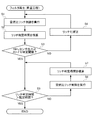
図6は、フィルタ再生処理の昇温工程の手順を示すフローチャートである。図6に示す処理は、フィルタ再生制御部75により、フィルタの再生時期に達したことに応じて実行される。
S1では、CSFを昇温するため、混合気の空燃比をストイキよりリッチ側に制御する空燃比リッチ制御を実行し、続くS2では、S1の空燃比リッチ制御を開始してから経過した時間に相当するリッチ判定時間を積算する。S1の空燃比リッチ制御では、混合気の空燃比がストイキよりリッチ側に設定された所定の目標値になるように、吸気量、燃料噴射量及びEGR量等のエンジンの運転パラメータの目標値を定め、これら運転パラメータの目標値に基づいて吸気制御弁、燃料噴射弁及びEGR制御弁等を駆動制御する。ここで、各運転パラメータの目標値は、予め定められたマップを検索することで決定されたマップ値、又はこれらマップ値を後述のS4において補正した値が用いられる。
FIG. 6 is a flowchart showing the procedure of the temperature raising process of the filter regeneration process. The process shown in FIG. 6 is executed by the filter regeneration control unit 75 in response to reaching the filter regeneration time.
In S1, air-fuel ratio rich control for controlling the air-fuel ratio of the air-fuel mixture to be richer than stoichiometric is executed in order to raise the CSF, and in subsequent S2, the time elapsed since the start of air-fuel ratio rich control in S1 is executed. The corresponding rich determination time is integrated. In the air-fuel ratio rich control in S1, target values of engine operating parameters such as the intake air amount, the fuel injection amount, and the EGR amount are set so that the air-fuel ratio of the air-fuel mixture becomes a predetermined target value set to the rich side from the stoichiometry. The intake control valve, the fuel injection valve, the EGR control valve and the like are driven and controlled based on the target values of these operating parameters. Here, as the target value of each operation parameter, a map value determined by searching a predetermined map or a value obtained by correcting these map values in S4 described later is used.
S3では、NH3センサの検出信号の値がストイキ判定閾値以上であるか否かを判別する。S3の判別がNOの場合には、空燃比のリッチ化が未だ十分でないと判断し、S1で定めた運転パラメータの目標値を、空燃比がよりリッチ化されるように補正し(S4)、S1に移る。S3の判別がYESの場合には、十分にリッチ化されたと判断し、S5に移る。以上のように、S1〜S4では、NH3センサの検出信号に基づいて実際の排気の空燃比がストイキ又はストイキよりリッチ側になったと判定されるまで、混合気の空燃比をリッチ側へ補正する。 In S3, it is determined whether or not the value of the detection signal of the NH 3 sensor is greater than or equal to the stoichiometric determination threshold value. If the determination in S3 is NO, it is determined that the enrichment of the air-fuel ratio is not yet sufficient, and the target value of the operation parameter determined in S1 is corrected so that the air-fuel ratio is enriched (S4), Move to S1. If the determination in S3 is YES, it is determined that the enrichment is sufficiently performed, and the process proceeds to S5. As described above, in S1 to S4, the air-fuel ratio of the air-fuel mixture is corrected to the rich side until it is determined that the actual exhaust air-fuel ratio has become richer than stoichiometric or stoichiometric based on the detection signal of the NH 3 sensor. To do.
S5では、上記S2で積算を開始したリッチ判定時間が、予め定められた規定時間を経過したか否かを判別する。この規定時間は、CSFをPMの燃焼温度まで昇温するのに要する時間に相当する。S5の判別がNOの場合には、再び空燃比リッチ制御を実行し(S6)、リッチ判定時間を積算する(S7)。S5の判別がYESの場合には、CSFがPMの燃焼温度まで昇温したと判断し、この処理を終了する。 In S5, it is determined whether or not the rich determination time at which integration is started in S2 has passed a predetermined time. This specified time corresponds to the time required to raise the temperature of the CSF to the combustion temperature of PM. If the determination in S5 is NO, air-fuel ratio rich control is executed again (S6), and the rich determination time is integrated (S7). If the determination in S5 is YES, it is determined that the CSF has risen to the combustion temperature of PM, and this process is terminated.
以上のように、CSFの昇温工程においてNH3センサを利用して空燃比リッチ制御を実行することにより、例えばO2センサが無い場合であっても精度良く空燃比を制御でき、ひいてはCSFの昇温にかかる時間を短くできる。 As described above, by executing the air-fuel ratio rich control using the NH 3 sensor in the CSF temperature raising step, for example, even when there is no O 2 sensor, the air-fuel ratio can be accurately controlled. The time required for temperature rise can be shortened.
[空燃比制御部76]
例えばエンジンが低、中負荷にある場合、リーン運転下で上記尿素水噴射制御を行うことにより、排気中のCO及びHCはDOC及びCSFにおける酸化反応によって浄化し、NOxはNH3の存在下のSCR触媒における還元反応によって浄化できる。しかし高負荷になりエンジンから排出されるNOx量が増加すると、SCR触媒のみでは十分にNOxを浄化できない場合がある。そこで、空燃比制御部76は、例えばエンジンが低、中負荷にある場合は、混合気の空燃比がストイキよりリーン側になるようにリーン運転を行い、高負荷運転時などエンジンからのNOx排出量が増加する場合には、DOC及びCSFにおける三元浄化反応を利用してCO、HC及びNOxを浄化すべく、混合気の空燃比をストイキ又はその近傍に制御する。しかし、DOC及びCSFにおいて効率的に三元浄化反応を進行させるためには、排気管に設けられたセンサの出力に基づいて高い精度で空燃比をストイキ又はその近傍に制御する必要がある。以下、図7を参照して、このようなストイキ空燃比制御にNH3センサの出力信号に基づく空燃比判定を適用した例を説明する。
[Air-fuel ratio control unit 76]
For example, when the engine is at a low and medium load, the urea water injection control is performed under lean operation, so that CO and HC in the exhaust gas are purified by an oxidation reaction in DOC and CSF, and NOx is in the presence of NH 3 . It can be purified by a reduction reaction in the SCR catalyst. However, if the amount of NOx discharged from the engine increases due to a high load, NOx may not be sufficiently purified with only the SCR catalyst. Therefore, the air-fuel
図7は、ストイキ空燃比制御の手順を示すフローチャートである。図7に示す処理は、リーン運転を行っている間に所定のタイミングで空燃比制御部76により実行される。
S11では、エンジンからのNOx排出量に相関のあるパラメータの値が所定の閾値より大きいか否かを判別する。エンジンからのNOx排出量に相関のあるパラメータの値とは、NOx排出量の推定値、エンジンの要求トルク値、又は図示平均有効圧値などが挙げられる。NOx排出量の推定値は、燃料噴射量や回転数などエンジンの運転状態を示す複数のパラメータを引数として、既知の演算式や制御マップから算出される。エンジンの要求トルク値は、例えば図示しないアクセル開度センサの出力に基づいて算出される。また、図示平均有効圧は、例えば図示しない筒内圧センサの出力に基づいて算出される。S11の判別がNOの場合、リーン運転を継続すべくこの処理を終了する。
FIG. 7 is a flowchart showing a procedure of stoichiometric air-fuel ratio control. The process shown in FIG. 7 is executed by the air-fuel
In S11, it is determined whether or not the value of the parameter correlated with the NOx emission amount from the engine is larger than a predetermined threshold value. The parameter value correlated with the NOx emission amount from the engine includes an estimated value of NOx emission amount, a required torque value of the engine, or an indicated mean effective pressure value. The estimated value of the NOx emission amount is calculated from a known arithmetic expression or control map using a plurality of parameters indicating the engine operating state such as the fuel injection amount and the rotational speed as arguments. The required torque value of the engine is calculated based on the output of an accelerator opening sensor (not shown), for example. The indicated mean effective pressure is calculated based on, for example, the output of a cylinder pressure sensor (not shown). If the determination in S11 is NO, this process is terminated to continue the lean operation.
S11の判別がYESの場合、S12に移り、DOC及びCSFにおいて三元浄化反応によって排気を浄化すべく空燃比ストイキ制御を実行する。この空燃比ストイキ制御では、混合気の空燃比がストイキになるように、吸気量、燃料噴射量及びEGR量等のエンジンの運転パラメータのそれぞれの目標値を定め、これら運転パラメータの目標値に基づいて吸気制御弁、燃料噴射弁、及びEGR制御弁等を駆動制御する。ここで、運転パラメータの目標値は、予め定められたマップを検索することで決定されたマップ値、又はこれらマップ値を後述のS14又はS15において補正した値が用いられる。 If the determination in S11 is YES, the process moves to S12, and air-fuel ratio stoichiometric control is executed to purify the exhaust gas by the three-way purification reaction in the DOC and CSF. In this air-fuel ratio stoichiometric control, target values of engine operating parameters such as the intake air amount, fuel injection amount, and EGR amount are determined so that the air-fuel ratio of the air-fuel mixture becomes stoichiometric, and based on the target values of these operating parameters. The intake control valve, the fuel injection valve, the EGR control valve, and the like are driven and controlled. Here, the target value of the operation parameter is a map value determined by searching a predetermined map, or a value obtained by correcting these map values in S14 or S15 described later.
S13では、NH3センサの検出信号の値がストイキ判定閾値以上であるか否かを判別する。S13の判別がNOの場合には、運転パラメータの目標値を、空燃比がよりリッチ化される様に補正し(S14)、S11に移る。S13の判別がYESの場合には、運転パラメータの目標値を、空燃比がよりリーン化されるように補正し(S15)、S11に移る。 In S13, it is determined whether or not the value of the detection signal of the NH 3 sensor is greater than or equal to the stoichiometric determination threshold value. If the determination in S13 is NO, the target value of the operation parameter is corrected so that the air-fuel ratio becomes richer (S14), and the process proceeds to S11. If the determination in S13 is YES, the target value of the operation parameter is corrected so that the air-fuel ratio becomes leaner (S15), and the process proceeds to S11.
以上のように、NH3センサの検出信号に応じて空燃比をリッチ化したりリーン化したりすることにより、NH3センサの検出信号の値がストイキ判定閾値以上の状態(ストイキよりリッチ側)と、NH3センサの検出信号の値がストイキ判定閾値を下回った状態(ストイキよりリーン側)とが交互に実現され、結果として混合気の空燃比がストイキに近似的に制御される。 As described above, by or lean or rich air-fuel ratio in accordance with a detection signal of the NH 3 sensor, the NH 3 value of the detection signal of the sensor is equal to or greater than stoichiometric determination threshold state (richer than stoichiometric), The state in which the value of the detection signal of the NH 3 sensor falls below the stoichiometric determination threshold value (lean side from stoichiometric) is alternately realized, and as a result, the air-fuel ratio of the air-fuel mixture is approximately controlled to stoichiometric.
[高EGR制御部77]
ディーゼルエンジンの燃焼技術の1つとして、通常燃焼時よりもEGRガスが多くなるようにEGR制御弁を制御することによりNOx排出量やPM排出量を低減する技術が知られている。EGRガスの量を多くすると空燃比はリッチ方向へ変化する傾向があるため、このような高EGR制御を行う場合は、空燃比がリッチ方向へ変化しすぎないようにEGRガスの量を制御する必要がある。以下、図8を参照して、このような高EGR制御にNH3センサの検出信号に基づく空燃比判定を適用した例を説明する。
[High EGR control unit 77]
As one of the combustion techniques for diesel engines, there is known a technique for reducing the NOx emission amount and the PM emission amount by controlling an EGR control valve so that the EGR gas becomes larger than that during normal combustion. If the amount of EGR gas is increased, the air-fuel ratio tends to change in the rich direction. Therefore, when performing such high EGR control, the amount of EGR gas is controlled so that the air-fuel ratio does not change too much in the rich direction. There is a need. Hereinafter, an example in which air-fuel ratio determination based on the detection signal of the NH 3 sensor is applied to such high EGR control will be described with reference to FIG.
図8は、高EGR制御の手順を示すフローチャートである。図8に示す処理は、高EGR制御部77により、所定のタイミングで実行される。
S21では、所定の高EGR制御実行条件を満たしているか否かを判別する。S21の判別がYESの場合にはS22に移り、NOの場合にはこの処理を直ちに終了する。S22では、高EGR制御を実行し、S23に移る。S22の高EGR制御では、EGR量の目標値を定め、この目標値に基づいてEGR制御弁を駆動制御する。ここで、EGR量の目標値は、高EGR制御用に予め定められたマップを検索することで決定されたマップ値、又はこのマップ値を後述のS3において補正した値が用いられる。なお、このマップによれば、EGR量の目標値は、混合気の空燃比が弱リーン(ストイキよりややリーン側)になるように定められる。
FIG. 8 is a flowchart showing a procedure of high EGR control. The process shown in FIG. 8 is executed by the high EGR control unit 77 at a predetermined timing.
In S21, it is determined whether or not a predetermined high EGR control execution condition is satisfied. If the determination in S21 is YES, the process moves to S22, and if the determination is NO, this process is immediately terminated. In S22, high EGR control is executed, and the process proceeds to S23. In the high EGR control of S22, a target value of the EGR amount is determined, and the EGR control valve is driven and controlled based on the target value. Here, as the target value of the EGR amount, a map value determined by searching a map predetermined for high EGR control, or a value obtained by correcting this map value in S3 described later is used. According to this map, the target value of the EGR amount is determined so that the air-fuel ratio of the air-fuel mixture becomes slightly lean (slightly leaner than stoichiometric).
S23では、NH3センサの検出信号の値がストイキ判定閾値以上であるか否かを判別する。S23の判別がNOであり、排気の空燃比がストイキよりリーン側である場合にはS21に移る。S23の判別がYESであり、排気の空燃比がストイキ又はストイキよりリッチ側である場合には、空燃比がリッチ方向に変化しすぎていると判断し、EGR量の目標値を減量側に補正し(S24)、S21に移る。
以上のように、NH3センサの検出信号に応じてEGR量を減量側に補正することにより、空燃比を弱リーンに維持しながら高EGR制御を実行できる。
In S23, it is determined whether or not the value of the detection signal of the NH 3 sensor is greater than or equal to the stoichiometric determination threshold value. If the determination in S23 is NO and the air-fuel ratio of the exhaust is leaner than the stoichiometry, the process proceeds to S21. If the determination in S23 is YES and the air-fuel ratio of the exhaust gas is stoichiometric or richer than stoichiometric, it is determined that the air-fuel ratio has changed too much in the rich direction, and the target value of the EGR amount is corrected to the decreasing side. Then (S24), the process proceeds to S21.
As described above, by correcting the EGR amount to the decreasing side according to the detection signal of the NH 3 sensor, high EGR control can be executed while maintaining the air-fuel ratio at a weak lean level.
[SCR触媒劣化判定制御部78]
上述のように、SCR触媒は、基本的には酸素を多く含んだ排気が流れるリーン運転でのみNOxを浄化できる。このため、例えばリーン運転からストイキ又はリッチ運転に切り替えた際、過渡的に上記式(2)の反応を進行させるため、下流触媒コンバータ33には、排気中の酸素を吸蔵したり放出したりする酸素吸蔵放出材(OSC材)が設けられる場合がある。OSC材としては、例えば酸化セリウム(CeO2)が用いられる。このようにSCR触媒にOSC材を含めると、SCR触媒にかかる熱負荷とOSC材にかかる熱負荷が等しくなることから、OSC材の劣化度合いとSCR触媒の劣化度合いとを関連付けることができる。
[SCR catalyst deterioration determination control unit 78]
As described above, the SCR catalyst can basically purify NOx only in the lean operation in which the exhaust gas containing a large amount of oxygen flows. For this reason, for example, when the lean operation is switched to the stoichiometric or rich operation, the reaction of the above equation (2) is transiently advanced. Therefore, the downstream
SCR触媒劣化判定制御部78は、下流ストイキ判定部73による空燃比の判定結果を利用してOSC材の酸素吸蔵放出機能の低下を検出することにより、間接的にSCR触媒の浄化性能の低下を判定し、この判定結果に応じて触媒劣化警告灯45を点灯する。以下、図9を参照して、SCR触媒劣化判定制御部78における処理の手順を説明する。
The SCR catalyst deterioration
図9は、SCR触媒劣化判定制御の手順を示すフローチャートである。図9に示す処理は、リーン運転を行っている間に所定のタイミングでSCR触媒劣化判定制御部78によって実行される。
S31では、一定期間にわたり排気の酸素濃度を低下させるため、混合気の空燃比をストイキよりリッチ側に制御する空燃比リッチ制御を実行する。この空燃比リッチ制御では、混合気の空燃比がストイキよりリッチ側に設定された所定の目標値になるように、吸気量、燃料噴射量及びEGR量等のエンジンの運転パラメータの目標値を定め、これら運転パラメータの目標値に基づいて吸気制御弁、燃料噴射弁及びEGR制御弁等を駆動制御する。ここで、各運転パラメータの目標値は、例えば予め定められたマップを検索することで決定されたマップ値が用いられる。
FIG. 9 is a flowchart showing a procedure of SCR catalyst deterioration determination control. The process shown in FIG. 9 is executed by the SCR catalyst deterioration
In S31, air-fuel ratio rich control for controlling the air-fuel ratio of the air-fuel mixture to be richer than stoichiometric is performed in order to reduce the oxygen concentration of the exhaust gas over a certain period. In this air-fuel ratio rich control, target values of engine operating parameters such as the intake air amount, fuel injection amount, and EGR amount are determined so that the air-fuel ratio of the air-fuel mixture becomes a predetermined target value set to a richer side than stoichiometric. The intake control valve, the fuel injection valve, the EGR control valve, and the like are driven and controlled based on the target values of these operating parameters. Here, as the target value of each operation parameter, for example, a map value determined by searching a predetermined map is used.
S32では、上流ストイキ判定部により下流触媒コンバータの上流側の排気の空燃比がストイキ又はストイキよりリッチ側になったと判定されたか否か、すなわち上流ストイキ判定部によりO2センサの検出信号の値がストイキ判定閾値以上になったと判定されたか否かを判別する。S32の判別がNOの場合にはS31に移り、空燃比リッチ制御を継続して実行する。S32の判別がYESの場合には、S33に移る。S33では、下流触媒コンバータの上流側の排気の空燃比がストイキ又はストイキよりリッチ側になってから経過した時間に相当するリッチ判定時間を積算し、S34に移る。S34では、下流ストイキ判定部により下流触媒コンバータの下流側の排気の空燃比がストイキ又はストイキよりリッチ側になったと判定されたか否か、すなわち下流ストイキ判定部によりNH3センサの検出信号の値がストイキ判定閾値以上になったと判定されたか否かを判別する。S34の判別がNOの場合には、S31に移り、空燃比リッチ制御を継続して実行する。S34の判別がYESの場合には、下流触媒コンバータの上流側に引き続き下流側の排気の空燃比もストイキ又はストイキよりリッチ側になったと判断し、S35に移る。 In S32, whether or not the upstream stoichiometric determination unit determines that the air-fuel ratio of the exhaust gas upstream of the downstream catalytic converter has become richer than stoichiometric, that is, the upstream stoichiometric determination unit determines the value of the detection signal of the O 2 sensor. It is determined whether or not it is determined that the stoichiometric determination threshold is exceeded. When the determination in S32 is NO, the process proceeds to S31, and the air-fuel ratio rich control is continuously executed. If the determination in S32 is yes, the process proceeds to S33. In S33, the rich determination time corresponding to the time elapsed since the air-fuel ratio of the exhaust on the upstream side of the downstream catalytic converter has become richer than the stoichiometric value is integrated, and the process proceeds to S34. In S34, whether or not the downstream stoichiometric determination unit determines that the air-fuel ratio of the downstream exhaust of the downstream catalytic converter has become richer than stoichiometric or stoichiometric, that is, the value of the detection signal of the NH 3 sensor is determined by the downstream stoichiometric determination unit. It is determined whether or not it is determined that the stoichiometric determination threshold is exceeded. When the determination in S34 is NO, the process proceeds to S31, and the air-fuel ratio rich control is continuously executed. If the determination in S34 is YES, it is determined that the air-fuel ratio of the exhaust on the downstream side is also stoichiometric or richer than stoichiometric after the upstream side of the downstream catalytic converter, and the process proceeds to S35.
S35では、S32で積算したリッチ判定時間が、SCR触媒の劣化度合いを判定するために設定された劣化判定閾値以上であるか否かを判別する。このリッチ判定時間は、S31において空燃比リッチ制御を開始した後、O2センサの検出信号に基づいて下流触媒コンバータの上流側の排気の空燃比がストイキ又はストイキよりリッチ側になったと判定されてから、NH3センサの検出信号に基づいて下流触媒コンバータの下流側の排気の空燃比がストイキ又はストイキよりリッチ側になったと判定されるまでにかかった時間に相当する。下流触媒コンバータに設けられたOSC材の劣化が進み、その酸素吸蔵放出機能が低下するほどリッチ判定時間は短くなることから、このリッチ判定時間はSCR触媒の劣化度合いを判定するための目安となる。S35の判別がYESの場合には、SCR触媒は正常であると判定し(S36)、この処理を終了する。S35の判別がNOの場合には、SCR触媒は劣化した状態であると判定し、触媒劣化警告灯を点灯し(S37)、この処理を終了する。 In S35, it is determined whether or not the rich determination time accumulated in S32 is equal to or more than a deterioration determination threshold set for determining the deterioration degree of the SCR catalyst. This rich determination time is determined after the air-fuel ratio rich control is started in S31, and based on the detection signal of the O 2 sensor, it is determined that the air-fuel ratio of the exhaust on the upstream side of the downstream catalytic converter has become richer than stoichiometric or stoichiometric. From this, it corresponds to the time taken until it is determined that the air-fuel ratio of the exhaust gas downstream of the downstream catalytic converter becomes richer than stoichiometric based on the detection signal of the NH 3 sensor. The rich determination time becomes shorter as the OSC material provided in the downstream catalytic converter deteriorates and its oxygen storage / release function decreases, so this rich determination time is a measure for determining the degree of deterioration of the SCR catalyst. . If the determination in S35 is YES, it is determined that the SCR catalyst is normal (S36), and this process ends. If the determination in S35 is NO, it is determined that the SCR catalyst is in a deteriorated state, the catalyst deterioration warning lamp is turned on (S37), and this process is terminated.
以上、本発明の一実施形態について説明したが、本発明はこれに限るものではない。
例えば、上記式(7)に示すように、NH3センサの電極間に発生する起電力はセンサ温度Tに比例している。このため、通常NH3出力範囲や、酸素濃度が0又はその近傍まで低下したときに発生する起電力の大きさもセンサ温度Tによって変化する。したがって、通常NH3出力範囲や、NH3センサの検出信号に基づいて排気の空燃比を判定するためのストイキ判定閾値については、センサ温度に応じて変化させてもよい。なお、センサ温度は、センサ素子のヒータ電流や排気温度等に基づいて推定することができる。
Although one embodiment of the present invention has been described above, the present invention is not limited to this.
For example, as shown in the above formula (7), the electromotive force generated between the electrodes of the NH 3 sensor is proportional to the sensor temperature T. For this reason, the normal NH 3 output range and the magnitude of the electromotive force generated when the oxygen concentration is reduced to 0 or in the vicinity thereof also vary depending on the sensor temperature T. Therefore, the stoichiometric determination threshold value for determining the air / fuel ratio of the exhaust based on the normal NH 3 output range or the detection signal of the NH 3 sensor may be changed according to the sensor temperature. The sensor temperature can be estimated based on the heater current of the sensor element, the exhaust temperature, and the like.
なお、図9に示す例では、O2センサの検出信号に基づいて下流触媒コンバータの上流側の排気の空燃比がストイキ又はストイキよりリッチ側になったと判定されたことに応じて、リッチ判定時間の積算を開始したが、リッチ判定時間の積算の始期はこれに限らない。空燃比リッチ制御を開始してから下流触媒コンバータの上流側の排気の空燃比がストイキ又はストイキよりリッチ側になるまでにかかる時間は、予め行われた実験等に基づいて推定することもできる。したがって、O2センサを備えないシステムでは、下流触媒コンバータの上流側の排気の空燃比がストイキ又はストイキよりリッチ側になるタイミングを推定し、これに応じてリッチ判定時間の積算を開始しても、上記図8に示す処理とほぼ同じ効果を奏する。 In the example shown in FIG. 9, the rich determination time is determined in response to the determination that the air-fuel ratio of the exhaust on the upstream side of the downstream catalytic converter is richer than stoichiometric based on the detection signal of the O 2 sensor. However, the start of accumulation of the rich determination time is not limited to this. The time required from the start of the air-fuel ratio rich control until the air-fuel ratio of the exhaust on the upstream side of the downstream catalytic converter becomes richer than the stoichiometric value can also be estimated based on experiments conducted in advance. Therefore, in a system that does not include the O 2 sensor, the timing at which the air-fuel ratio of the exhaust on the upstream side of the downstream catalytic converter becomes richer than stoichiometric is estimated, and the accumulation of the rich determination time is started accordingly. The same effect as the process shown in FIG. 8 is obtained.
1…エンジン(内燃機関)
11…排気管(排気通路)
13…EGR装置(EGR装置)
2…排気浄化システム
33…下流触媒コンバータ(SCR触媒)
4…尿素水供給装置(還元剤供給装置)
31…上流触媒コンバータ(上流触媒)
32…排気浄化フィルタ(上流触媒)
5…NH3センサ(アンモニアセンサ)
53…基準電極
52…検知電極
51…固体電解質層
72…NH3濃度算出部(アンモニア濃度算出手段)
73…下流ストイキ判定部(ストイキ判定手段)
74…尿素水噴射制御部(還元剤供給量制御手段)
76…空燃比制御部(空燃比制御手段)
77…高EGR制御部(EGR制御手段)
78…SCR触媒劣化判定制御部(触媒劣化判定手段)
1. Engine (internal combustion engine)
11 ... Exhaust pipe (exhaust passage)
13 ... EGR device (EGR device)
2 ...
4 ... Urea water supply device (reducing agent supply device)
31 ... Upstream catalytic converter (upstream catalyst)
32. Exhaust gas purification filter (upstream catalyst)
5 ... NH 3 sensor (ammonia sensor)
53 ... reference electrode 52 ... detection electrode 51 ...
73: Downstream stoichiometric determination unit (stoichiometric determining means)
74: urea water injection control unit (reducing agent supply amount control means)
76: Air-fuel ratio control section (air-fuel ratio control means)
77 ... High EGR control section (EGR control means)
78 ... SCR catalyst deterioration determination control unit (catalyst deterioration determination means)
Claims (8)
前記選択還元触媒の上流側にアンモニア又はその前駆体を還元剤として供給する還元剤供給装置と、
酸素に対する活性を有する基準電極と、酸素及びアンモニアに対する活性を有する検知電極と、これら検知電極及び基準電極が設けられた酸素イオン導電性の固体電解質とを備えたアンモニアセンサと、
前記アンモニアセンサの検出信号に応じて還元剤の供給量を制御する還元剤供給量制御手段と、を備えた内燃機関の排気浄化システムであって、
前記基準電極と前記検知電極は、前記排気通路内のうち前記選択還元触媒の下流側に同じ排気に晒されるように設けられ、
前記アンモニアセンサの検出信号の値が所定のストイキ判定閾値を超えて変化した場合には、前記選択還元触媒の下流側の排気の空燃比がストイキよりリーン側からストイキ又はストイキよりリッチ側になったと判定するストイキ判定手段をさらに備えることを特徴とする内燃機関の排気浄化システム。 A selective reduction catalyst that is provided in an exhaust passage of the internal combustion engine and selectively reduces nitrogen oxides in the exhaust in the presence of ammonia;
A reducing agent supply device for supplying ammonia or a precursor thereof as a reducing agent upstream of the selective reduction catalyst;
An ammonia sensor comprising a reference electrode having activity against oxygen, a sensing electrode having activity against oxygen and ammonia, and an oxygen ion conductive solid electrolyte provided with these sensing electrode and reference electrode;
An exhaust gas purification system for an internal combustion engine, comprising a reducing agent supply amount control means for controlling a supply amount of the reducing agent according to a detection signal of the ammonia sensor,
The reference electrode and the detection electrode are provided in the exhaust passage so as to be exposed to the same exhaust gas downstream of the selective reduction catalyst,
When the value of the detection signal of the ammonia sensor has changed beyond a predetermined stoichiometric determination threshold, the air-fuel ratio of the exhaust downstream of the selective reduction catalyst has changed from lean to lean or stoichiometric from the stoichiometric side. An exhaust purification system for an internal combustion engine, further comprising stoichiometric determination means for determining.
前記還元剤供給量制御手段は、前記算出されたアンモニア濃度に基づいて還元剤の供給量を制御することを特徴とする請求項1に記載の内燃機関の排気浄化システム。 When the value of the detection signal of the ammonia sensor is within a normal output range set inside the stoichiometric determination threshold, the ammonia in the exhaust gas downstream of the selective reduction catalyst based on the detection signal of the ammonia sensor An ammonia concentration calculation means for calculating the concentration;
2. The exhaust gas purification system for an internal combustion engine according to claim 1, wherein the reducing agent supply amount control means controls the supply amount of the reducing agent based on the calculated ammonia concentration.
前記機関のNOx排出量に相関のあるパラメータの値が所定の閾値以下である場合には、混合気の空燃比をストイキよりリーン側に制御し、前記パラメータの値が前記閾値より大きい場合には、前記ストイキ判定手段による判定に基づいて混合気の空燃比をストイキに制御する空燃比制御手段と、をさらに備えることを特徴とする請求項1から3の何れかに記載の内燃機関の排気浄化システム。 An upstream catalyst provided on the upstream side of the selective reduction catalyst in the exhaust passage and having a three-way purification function;
When the value of the parameter correlated with the NOx emission amount of the engine is equal to or less than a predetermined threshold, the air-fuel ratio of the air-fuel mixture is controlled to be leaner than the stoichiometric, and when the value of the parameter is larger than the threshold The exhaust gas purification of an internal combustion engine according to any one of claims 1 to 3, further comprising air-fuel ratio control means for controlling the air-fuel ratio of the air-fuel mixture to stoichiometric based on determination by the stoichiometric determination means. system.
前記EGR装置による排気還流量を制御するEGR制御手段と、をさらに備え、
前記EGR制御手段は、前記ストイキ判定手段により空燃比がストイキ又はストイキよりリッチ側になったと判定されたことに応じて、排気還流量を減量側に補正することを特徴とする請求項1から4の何れかに記載の内燃機関の排気浄化システム。 An EGR device that recirculates a portion of the exhaust gas flowing through the exhaust passage to the intake passage;
EGR control means for controlling the exhaust gas recirculation amount by the EGR device,
5. The EGR control means corrects the exhaust gas recirculation amount to a decrease side when the stoichiometric determination means determines that the air-fuel ratio has become richer than stoichiometric or stoichiometric. 5. An exhaust purification system for an internal combustion engine according to any one of the above.
混合気の空燃比をストイキ又はストイキよりリッチ側にする制御を開始した後の所定の時期から、前記ストイキ判定手段により前記選択還元触媒の下流側の空燃比がストイキ又はストイキよりリッチ側になったと判定されるまでにかかった時間を測定し、当該測定時間に基づいて前記選択還元触媒の劣化を判定する触媒劣化判定手段をさらに備えることを特徴とする請求項1から3の何れかに記載の内燃機関の排気浄化システム。 The selective reduction catalyst includes an oxygen storage / release material,
When the air-fuel ratio on the downstream side of the selective reduction catalyst has become richer than stoichiometric or stoichiometric by the stoichiometric determination means from a predetermined time after starting the control to make the air-fuel ratio of the air-fuel mixture stoichiometric or richer than stoichiometric 4. The catalyst deterioration determination unit according to claim 1, further comprising a catalyst deterioration determination unit that measures a time taken until the determination, and determines deterioration of the selective reduction catalyst based on the measurement time. An exhaust purification system for an internal combustion engine.
前記選択還元触媒の上流側にアンモニア又はその前駆体を還元剤として供給する還元剤供給装置と、
前記選択還元触媒の下流側に設けられ、排気中の少なくともアンモニア及び酸素の濃度に応じた起電力を検出信号として電極間に発生するアンモニアセンサと、
前記アンモニアセンサの検出信号に基づいて還元剤の供給量を制御する還元剤供給量制御手段と、を備えた内燃機関の排気浄化システムであって、
前記アンモニアセンサの電極間には、その周囲の排気の酸素濃度が0又はほぼ0になると、アンモニア濃度によらず所定のストイキ判定閾値を超える起電力が発生し、
前記アンモニアセンサの検出信号の値が前記ストイキ判定閾値を超えて変化した場合には、前記選択還元触媒の下流側の排気の空燃比がストイキよりリーン側からストイキ又はストイキよりリッチ側になったと判定するストイキ判定手段をさらに備えることを特徴とする内燃機関の排気浄化システム。 A selective reduction catalyst that is provided in an exhaust passage of the internal combustion engine and selectively reduces nitrogen oxides in the exhaust in the presence of ammonia;
A reducing agent supply device for supplying ammonia or a precursor thereof as a reducing agent upstream of the selective reduction catalyst;
An ammonia sensor that is provided on the downstream side of the selective reduction catalyst, and that generates an electromotive force according to the concentration of at least ammonia and oxygen in the exhaust as a detection signal between the electrodes;
An exhaust gas purification system for an internal combustion engine comprising a reducing agent supply amount control means for controlling a supply amount of the reducing agent based on a detection signal of the ammonia sensor,
When the oxygen concentration of the surrounding exhaust gas becomes 0 or almost 0 between the electrodes of the ammonia sensor, an electromotive force exceeding a predetermined stoichiometric threshold is generated regardless of the ammonia concentration,
When the value of the detection signal of the ammonia sensor changes beyond the stoichiometric determination threshold value, it is determined that the air-fuel ratio of the exhaust gas downstream of the selective reduction catalyst has changed from lean to lean or stoichiometric. An exhaust purification system for an internal combustion engine, further comprising:
前記還元剤供給量制御手段は、前記算出されたアンモニア濃度に基づいて還元剤の供給量を制御することを特徴とする請求項7に記載の内燃機関の排気浄化システム。 When the value of the detection signal of the ammonia sensor is within a normal output range set inside the stoichiometric determination threshold, the ammonia in the exhaust gas downstream of the selective reduction catalyst based on the detection signal of the ammonia sensor An ammonia concentration calculation means for calculating the concentration;
The exhaust gas purification system for an internal combustion engine according to claim 7, wherein the reducing agent supply amount control means controls the supply amount of the reducing agent based on the calculated ammonia concentration.
Priority Applications (1)
| Application Number | Priority Date | Filing Date | Title |
|---|---|---|---|
| JP2012179375A JP5812952B2 (en) | 2012-08-13 | 2012-08-13 | Exhaust gas purification system for internal combustion engine |
Applications Claiming Priority (1)
| Application Number | Priority Date | Filing Date | Title |
|---|---|---|---|
| JP2012179375A JP5812952B2 (en) | 2012-08-13 | 2012-08-13 | Exhaust gas purification system for internal combustion engine |
Publications (3)
| Publication Number | Publication Date |
|---|---|
| JP2014037787A JP2014037787A (en) | 2014-02-27 |
| JP2014037787A5 JP2014037787A5 (en) | 2014-04-10 |
| JP5812952B2 true JP5812952B2 (en) | 2015-11-17 |
Family
ID=50286099
Family Applications (1)
| Application Number | Title | Priority Date | Filing Date |
|---|---|---|---|
| JP2012179375A Expired - Fee Related JP5812952B2 (en) | 2012-08-13 | 2012-08-13 | Exhaust gas purification system for internal combustion engine |
Country Status (1)
| Country | Link |
|---|---|
| JP (1) | JP5812952B2 (en) |
Families Citing this family (11)
| Publication number | Priority date | Publication date | Assignee | Title |
|---|---|---|---|---|
| JP6102908B2 (en) * | 2014-12-26 | 2017-03-29 | トヨタ自動車株式会社 | Exhaust purification device deterioration diagnosis device |
| JP6102907B2 (en) * | 2014-12-26 | 2017-03-29 | トヨタ自動車株式会社 | Exhaust purification device deterioration diagnosis device |
| JP2016166546A (en) * | 2015-03-09 | 2016-09-15 | 本田技研工業株式会社 | Device for detecting failure of nh3 sensor |
| JP2016166757A (en) * | 2015-03-09 | 2016-09-15 | 本田技研工業株式会社 | Failure detection method of nh3 sensor |
| JP2017067041A (en) * | 2015-10-01 | 2017-04-06 | 本田技研工業株式会社 | Exhaust emission control system for internal combustion engine |
| JP6483004B2 (en) * | 2015-10-19 | 2019-03-13 | 本田技研工業株式会社 | Humidity estimation method and exhaust purification system for internal combustion engine |
| JP6278039B2 (en) * | 2015-12-14 | 2018-02-14 | トヨタ自動車株式会社 | Degradation diagnosis device for selective catalytic reduction catalyst |
| JP6867921B2 (en) * | 2016-10-24 | 2021-05-12 | 日本碍子株式会社 | Ammonia concentration measuring device, ammonia concentration measuring system, exhaust gas treatment system, and ammonia concentration measuring method |
| DE102017202574A1 (en) * | 2017-02-17 | 2018-08-23 | Ford Global Technologies, Llc | Method for operating an exhaust gas aftertreatment device of a motor vehicle |
| CN114000937B (en) * | 2021-10-29 | 2023-03-24 | 潍柴动力股份有限公司 | Automatic recognition cleaning device for urea crystallization and control method thereof |
| CN115962057B (en) * | 2022-12-29 | 2024-08-16 | 潍柴动力股份有限公司 | Engine emission control method and device |
Family Cites Families (3)
| Publication number | Priority date | Publication date | Assignee | Title |
|---|---|---|---|---|
| JP4211232B2 (en) * | 2001-04-19 | 2009-01-21 | トヨタ自動車株式会社 | Exhaust gas sensor |
| JP5033017B2 (en) * | 2008-02-22 | 2012-09-26 | 日本特殊陶業株式会社 | Ammonia gas sensor |
| JP2010139238A (en) * | 2008-12-09 | 2010-06-24 | Ngk Spark Plug Co Ltd | Ammonia gas sensor |
-
2012
- 2012-08-13 JP JP2012179375A patent/JP5812952B2/en not_active Expired - Fee Related
Also Published As
| Publication number | Publication date |
|---|---|
| JP2014037787A (en) | 2014-02-27 |
Similar Documents
| Publication | Publication Date | Title |
|---|---|---|
| JP5812952B2 (en) | Exhaust gas purification system for internal combustion engine | |
| US8359841B2 (en) | Exhaust purifying apparatus for an internal combustion engine | |
| JP5843699B2 (en) | Exhaust gas purification system for internal combustion engine | |
| WO2010032481A1 (en) | Output calibrator for nox sensor and method of output calibration | |
| KR101442391B1 (en) | Emission control system for internal combustion engine | |
| JP2009175013A (en) | Degradation diagnosing apparatus of nox sensor | |
| JP5910759B2 (en) | Exhaust gas purification system for internal combustion engine | |
| US10006333B1 (en) | Exhaust gas control apparatus for internal combustion engine | |
| JPWO2013035155A1 (en) | Exhaust gas purification device for internal combustion engine | |
| US10060318B2 (en) | Method for operating a driving system and corresponding driving system | |
| JP2019152137A (en) | Exhaust emission control device for internal combustion engine | |
| JP2009156159A (en) | Device for determining abnormal section of exhaust emission control system | |
| JP6248978B2 (en) | Control device for internal combustion engine | |
| JP6149940B2 (en) | Exhaust gas purification device for internal combustion engine | |
| JP2007046494A (en) | Air-fuel ratio control device for internal combustion engine | |
| JP2009175014A (en) | Nox sensor and its deterioration diagnosing apparatus | |
| JP2005105871A (en) | Catalyst control device and catalyst deterioration determining device for internal combustion engine | |
| JP6112093B2 (en) | Exhaust purification system | |
| JP2009036055A (en) | Control device of exhaust gas treatment device | |
| JP2017040226A (en) | Exhaust emission control device for internal combustion engine | |
| JP2009180150A (en) | Abnormality determination device of nox sensor used for exhaust emission control system | |
| JP5359360B2 (en) | Exhaust gas purification device for internal combustion engine | |
| JP2013238170A (en) | Exhaust cleaning system for internal combustion engine | |
| JP2016166546A (en) | Device for detecting failure of nh3 sensor | |
| JP2009243316A (en) | Exhaust emission control device and its exhaust emission control method |
Legal Events
| Date | Code | Title | Description |
|---|---|---|---|
| A521 | Request for written amendment filed |
Free format text: JAPANESE INTERMEDIATE CODE: A523 Effective date: 20140207 |
|
| A621 | Written request for application examination |
Free format text: JAPANESE INTERMEDIATE CODE: A621 Effective date: 20141128 |
|
| A977 | Report on retrieval |
Free format text: JAPANESE INTERMEDIATE CODE: A971007 Effective date: 20150811 |
|
| TRDD | Decision of grant or rejection written | ||
| A01 | Written decision to grant a patent or to grant a registration (utility model) |
Free format text: JAPANESE INTERMEDIATE CODE: A01 Effective date: 20150818 |
|
| A61 | First payment of annual fees (during grant procedure) |
Free format text: JAPANESE INTERMEDIATE CODE: A61 Effective date: 20150915 |
|
| R150 | Certificate of patent or registration of utility model |
Ref document number: 5812952 Country of ref document: JP Free format text: JAPANESE INTERMEDIATE CODE: R150 |
|
| LAPS | Cancellation because of no payment of annual fees |