JP5810582B2 - Robot control method and robot - Google Patents
Robot control method and robot Download PDFInfo
- Publication number
- JP5810582B2 JP5810582B2 JP2011073562A JP2011073562A JP5810582B2 JP 5810582 B2 JP5810582 B2 JP 5810582B2 JP 2011073562 A JP2011073562 A JP 2011073562A JP 2011073562 A JP2011073562 A JP 2011073562A JP 5810582 B2 JP5810582 B2 JP 5810582B2
- Authority
- JP
- Japan
- Prior art keywords
- robot
- work
- workpiece
- control method
- gripping
- Prior art date
- Legal status (The legal status is an assumption and is not a legal conclusion. Google has not performed a legal analysis and makes no representation as to the accuracy of the status listed.)
- Expired - Fee Related
Links
Images


Classifications
-
- B—PERFORMING OPERATIONS; TRANSPORTING
- B25—HAND TOOLS; PORTABLE POWER-DRIVEN TOOLS; MANIPULATORS
- B25J—MANIPULATORS; CHAMBERS PROVIDED WITH MANIPULATION DEVICES
- B25J9/00—Programme-controlled manipulators
- B25J9/16—Programme controls
- B25J9/1656—Programme controls characterised by programming, planning systems for manipulators
- B25J9/1669—Programme controls characterised by programming, planning systems for manipulators characterised by special application, e.g. multi-arm co-operation, assembly, grasping
-
- B—PERFORMING OPERATIONS; TRANSPORTING
- B25—HAND TOOLS; PORTABLE POWER-DRIVEN TOOLS; MANIPULATORS
- B25J—MANIPULATORS; CHAMBERS PROVIDED WITH MANIPULATION DEVICES
- B25J13/00—Controls for manipulators
- B25J13/08—Controls for manipulators by means of sensing devices, e.g. viewing or touching devices
- B25J13/081—Touching devices, e.g. pressure-sensitive
- B25J13/082—Grasping-force detectors
-
- B—PERFORMING OPERATIONS; TRANSPORTING
- B25—HAND TOOLS; PORTABLE POWER-DRIVEN TOOLS; MANIPULATORS
- B25J—MANIPULATORS; CHAMBERS PROVIDED WITH MANIPULATION DEVICES
- B25J9/00—Programme-controlled manipulators
- B25J9/0096—Programme-controlled manipulators co-operating with a working support, e.g. work-table
-
- B—PERFORMING OPERATIONS; TRANSPORTING
- B25—HAND TOOLS; PORTABLE POWER-DRIVEN TOOLS; MANIPULATORS
- B25J—MANIPULATORS; CHAMBERS PROVIDED WITH MANIPULATION DEVICES
- B25J9/00—Programme-controlled manipulators
- B25J9/16—Programme controls
- B25J9/1612—Programme controls characterised by the hand, wrist, grip control
-
- G—PHYSICS
- G05—CONTROLLING; REGULATING
- G05B—CONTROL OR REGULATING SYSTEMS IN GENERAL; FUNCTIONAL ELEMENTS OF SUCH SYSTEMS; MONITORING OR TESTING ARRANGEMENTS FOR SUCH SYSTEMS OR ELEMENTS
- G05B2219/00—Program-control systems
- G05B2219/30—Nc systems
- G05B2219/39—Robotics, robotics to robotics hand
- G05B2219/39479—Grip, release again to put object in correct position in tray, regrip and move
Description
本発明は、ロボットの制御方法、およびロボットに関する。 The present invention relates to a robot control method and a robot.
ロボット(ロボット装置)を用いて、作業対象物であるワークを把持しつつ該ワークに別の部品等を組み付ける作業を行う場合、ワークの座標系、すなわち位置とその姿勢等を把握することが必要となる。そのため、例えば特許文献1に示すように、ワークと該ワークに組み付ける部品の双方を、位置検出手段等を備えたロボットで把持しつつ、組み付け作業を行うロボットの制御方法が提示されている。しかし、ワークをロボット(より具体的には該ロボットが備えるハンド部)だけで固定して該ワークに対する組み付け作業を行う場合、該ロボットに必要とされる把持力が増大する。すなわち、ハンド部に駆動力の大きなアクチュエーターが必要となり、結果として、ロボットの重量、サイズ、及びコストが増加してしまう。 When a robot (robot device) is used to hold a workpiece, which is a work target, and to assemble another part or the like on the workpiece, it is necessary to know the coordinate system of the workpiece, that is, the position and its posture. It becomes. Therefore, for example, as shown in Patent Document 1, a robot control method for performing an assembly operation while holding both a workpiece and a component to be assembled to the workpiece by a robot having a position detection unit or the like is proposed. However, when an assembly operation is performed on a workpiece by fixing the workpiece only with a robot (more specifically, a hand unit included in the robot), the gripping force required for the robot increases. That is, an actuator having a large driving force is required for the hand unit, and as a result, the weight, size, and cost of the robot increase.
かかる状況に対応する方法、すなわちロボットのハンド部に過大な負荷をかけることなくワークを固定する方法として、例えば特許文献2に示すように、ワークを平面上に載置し、該ワークの重量を平面に負担させつつハンド部で該ワークを把持するロボットの方法が提示されている。 As a method corresponding to such a situation, that is, as a method of fixing the work without applying an excessive load to the robot hand, for example, as shown in Patent Document 2, the work is placed on a plane and the weight of the work is set. There has been proposed a robot method for gripping the workpiece with a hand portion while placing a burden on a plane.
しかし、上述のロボットの制御方法は、ワークと平面との座標系を合せる調整作業に時間を要するという課題がある。上述の座標系が合っていない状態でワークを把持した場合、組み付け作業の精度が合わなくなってしまう。そのため、組み付け精度の向上と作業効率との両立が困難であるという課題がある。 However, the above-described robot control method has a problem that it takes time to perform an adjustment operation to match the coordinate system of the workpiece and the plane. If the workpiece is gripped in the state where the above coordinate system is not suitable, the accuracy of the assembly work will not be suitable. Therefore, there is a problem that it is difficult to achieve both improvement in assembly accuracy and work efficiency.
本発明は、上述の課題の少なくとも一部を解決するためになされたものであり、以下の形態または適用例として実現することが可能である。 SUMMARY An advantage of some aspects of the invention is to solve at least a part of the problems described above, and the invention can be implemented as the following forms or application examples.
[適用例1]本適用例にかかるロボットの制御方法は、ハンド部でワークを把持する把持工程と、上記ワークを平面の近傍まで移送する移送工程と、上記ハンド部の把持力を低減することにより上記ワークを上記平面に落下させて、上記ワークを上記平面に倣わせる開放工程と、上記平面に倣った上記ワークを上記ハンド部で再度把持する再把持工程と、を含むことを特徴とする。 [Application Example 1] A robot control method according to this application example includes a gripping step of gripping a workpiece by a hand unit, a transfer step of transporting the workpiece to the vicinity of a plane, and a gripping force of the hand unit. And the step of dropping the workpiece onto the plane to cause the workpiece to follow the plane, and the step of re-gripping the workpiece following the plane with the hand portion again. To do.
このようなロボットの制御方法であれば、平面上に位置するワークを再度把持するため、最初に把持したときの座標とは関係なく平面に対して座標が合わされた状態のワークを把持できる。すなわち平面を利用して自動的に座標合わせができる。したがって、ワークの座標系と平面の座標系とを容易に合せることができる。そして、座標系が合された状態のワークを、重量を平面に負担させつつハンド部で把持できる。したがって、ワークに別の部品等を組み付ける作業を実施する場合において、組み付け精度の向上と作業効率の向上とを両立できる。また、平面が作業台である場合、また、別の作業台への移送も容易となる。
なお、上述の「平面の近傍まで移送」とは、平面視で上記平面内に収まる位置までワークを移送することとワークを垂直方向(重力方向)において平面に近づけることの双方を含んでいる。すなわち、水平方向の移動と垂直方向の移動との双方を含んでいる。また、「近傍」とは、ワークの一部が接触することも含んでいる。
With such a robot control method, since the workpiece located on the plane is gripped again, it is possible to grip the workpiece in which the coordinates are aligned with the plane regardless of the coordinates at the time of first gripping. That is, coordinates can be automatically adjusted using a plane. Therefore, the coordinate system of the workpiece and the coordinate system of the plane can be easily matched. And the workpiece | work of the state in which the coordinate system was united can be hold | gripped with a hand part, bearing a weight on a plane. Therefore, when performing the operation | work which assembles | assembles another components etc. to a workpiece | work, improvement of an assembly | attachment precision and improvement of work efficiency can be made compatible. Further, when the plane is a work table, the transfer to another work table is also facilitated.
The above-mentioned “transfer to the vicinity of the plane” includes both transferring the workpiece to a position that fits in the plane in plan view and bringing the workpiece close to the plane in the vertical direction (gravity direction). That is, both horizontal movement and vertical movement are included. In addition, “near” includes that a part of the workpiece comes into contact.
[適用例2]上述のロボットの制御方法であって、上記ハンド部は上記ワークと上記平面との接触を検出可能なセンサーを備え、上記移送工程は、上記センサーが上記ワークの一部と上記平面との接触を検出するまで、上記ハンド部を上記平面に接近させることを特徴とするロボットの制御方法。 Application Example 2 In the above-described robot control method, the hand unit includes a sensor capable of detecting contact between the workpiece and the plane. In the transfer step, the sensor includes a part of the workpiece and the sensor. A robot control method, wherein the hand unit is brought close to the plane until contact with the plane is detected.
このようなロボットの制御方法であれば、開放工程においてワークが落下する距離を低減できる。したがって、開放工程を実施する際のワークへの衝撃等を低減できる。 With such a robot control method, it is possible to reduce the distance at which the workpiece falls in the opening process. Accordingly, it is possible to reduce the impact on the workpiece when the opening process is performed.
[適用例3]上述のロボットの制御方法であって、上記センサーは、上記ワークに加わる圧力を測定する圧力センサーと、上記ハンド部に加わる力を測定する力覚センサーと、上記ワークと上記平面との間隔を撮像する画像センサーと、の3種類のセンサーのうちのいずれかであることを特徴とするロボットの制御方法。 Application Example 3 In the robot control method described above, the sensor includes a pressure sensor that measures a pressure applied to the workpiece, a force sensor that measures a force applied to the hand unit, the workpiece and the plane. And a robot control method characterized by being one of three types of sensors.
このようなロボットの制御方法であれば、ワークの一部と平面との接触を確実に検出できる。したがって、移送工程及び開放工程を実施する際のワークへの影響を低減できる。 With such a robot control method, it is possible to reliably detect contact between a part of a workpiece and a flat surface. Therefore, the influence on the workpiece | work at the time of implementing a transfer process and an open process can be reduced.
[適用例4]上述のロボットの制御方法であって、上記平面は略水平面であり、上記再把持工程は、上記開放工程を開始してから所定の時間が経過した後に実施される工程であることを特徴とするロボットの制御方法。 Application Example 4 In the robot control method described above, the plane is a substantially horizontal plane, and the re-gripping step is a step that is performed after a predetermined time has elapsed since the opening step was started. A robot control method characterized by the above.
このようなロボットの制御方法であれば、開放工程の実施直後に、平面上でワークが振動した場合でも、該振動が収まった後に際把持できる。また、上述の振動等を検出するセンサー等を用いることなく、平面に倣った状態で停止したワークを再度把持することができる。したがって、コストを増加させることなく、かつ効率的に上述の組み付け作業を実施できる。 With such a robot control method, even if the workpiece vibrates on a plane immediately after the opening process, the robot can be gripped after the vibration has subsided. In addition, the workpiece stopped in a state of following the plane can be gripped again without using a sensor or the like for detecting the above-described vibration or the like. Therefore, the above assembling work can be efficiently performed without increasing the cost.
[適用例5]上述のロボットの制御方法であって、上記ロボットは、上記ハンド部の上記ワークと接触する部分に、上記ハンド部に対する上記ワークの滑り量を測定する滑りセンサーを備え、上記開放工程は、単位時間当たりの上記滑り量がしきい値以下となるように、上記ハンド部の把持力を調整しつつ実施する工程であることを特徴とするロボットの制御方法。 Application Example 5 In the above-described robot control method, the robot includes a slip sensor that measures a slip amount of the work with respect to the hand portion at a portion of the hand portion that contacts the work, and the opening is performed. The process is a process for controlling a robot, which is performed while adjusting the gripping force of the hand unit so that the slip amount per unit time is equal to or less than a threshold value.
このようなロボットの制御方法であれば、開放工程において、平面に対してワークを徐々に接近させることができる。したがって、ワークを自由落下させる場合に比べて、ワークに加わる衝撃を低減できる。なお、上記のしきい値とは、開放工程においてワークの損傷等を充分に回避できる程度の値であり、ワークによって異なる値である。 With such a robot control method, the workpiece can gradually approach the plane in the opening process. Therefore, the impact applied to the workpiece can be reduced as compared with the case where the workpiece is freely dropped. The above threshold value is a value that can sufficiently avoid damage to the workpiece in the opening process, and is a value that varies depending on the workpiece.
[適用例6]上述の制御方法であって、上記再把持工程は、上記開放工程を開始してから所定の時間が経過した後に実施されることを特徴とするロボットの制御方法。 Application Example 6 In the above-described control method, the re-gripping step is performed after a predetermined time has elapsed since the opening step was started.
このようなロボットの制御方法であれば、ワークが平面上に落下したこと検出するセンサー等を用いることなく、平面に倣った状態で停止したワークを再度把持することができる。したがって、コストを増加させることなく、かつ効率的に上述の組み付け作業を実施できる。 With such a robot control method, it is possible to grip a workpiece stopped in a state following the plane again without using a sensor or the like that detects that the workpiece has fallen on the plane. Therefore, the above assembling work can be efficiently performed without increasing the cost.
[適用例7]また、本適用例のロボットの制御方法は、平面部を有し上記平面部に対して間隔を有する位置でワークを把持できるハンド部を備えるロボットの制御方法であって、ハンド部でワークを把持するワーク把持工程と、上記ワークと上記平面部とを押し合せる座標合せ工程と、を含むことを特徴とする。 Application Example 7 A robot control method according to this application example is a robot control method including a hand portion that has a flat portion and can hold a workpiece at a position spaced from the flat portion. A workpiece gripping step of gripping the workpiece by the portion, and a coordinate alignment step of pressing the workpiece and the flat surface portion together.
このようなロボットの制御方法であれば、ハンド部の座標系とワークの座標系を容易に合せることができる。したがって、ハンド部の座標系との相対関係が既知の座標系を有する作業台に上記のワークを載置して該ワークに別の部品等を組み付ける作業を、ワークの座標系と作業台の座標系とを合せることなく実施できる。そのため、組み付け精度を落とすことなく、作業効率を向上できる。 With such a robot control method, the coordinate system of the hand unit and the coordinate system of the workpiece can be easily matched. Therefore, the work coordinate system and the work table coordinate system can be used to place the above work on a work table having a coordinate system with a known relative relationship with the coordinate system of the hand unit and to assemble another part on the work. It can be implemented without matching the system. Therefore, work efficiency can be improved without reducing the assembly accuracy.
[適用例8]上述のロボットの制御方法であって、上記座標合せ工程は、上記平面部が上記ハンド部の重力方向に位置するように上記ロボットを駆動する反転工程と、上記ハンド部の把持力を低減することにより上記ワークを上記平面部に落下させて、上記ワークを上記平面部に倣わせる開放工程と、を含むことを特徴とするロボットの制御方法。 Application Example 8 In the above-described robot control method, the coordinate aligning step includes a reversing step of driving the robot so that the plane portion is positioned in the gravitational direction of the hand portion, and gripping the hand portion. A robot control method comprising: an opening step of dropping the work onto the flat surface portion by reducing a force, and causing the work to follow the flat surface portion.
このようなロボットの制御方法であれば、ハンド部の把持力の加減のみで、ワークと平面部とを押し合せることができる。したがって、アームの構造を複雑化させずに、ハンド部の座標系とワークの座標系を容易に合せることができる。 With such a robot control method, the workpiece and the flat surface portion can be pressed together only by adjusting the gripping force of the hand portion. Therefore, the coordinate system of the hand unit and the coordinate system of the workpiece can be easily matched without complicating the arm structure.
[適用例9]上述の制御方法であって、上記ロボットは、上記ハンド部の上記ワークと接触する部分に、上記ハンド部に対する上記ワークの滑り量を測定する滑りセンサーを備えるロボットであり、上記開放工程は、単位時間当たりの上記滑り量がしきい値以下となるように、上記ハンド部の把持力を調整し上記ワークを落下させることを特徴とするロボットの制御方法。 Application Example 9 In the above control method, the robot includes a slip sensor that measures a slip amount of the work with respect to the hand part at a part of the hand part that comes into contact with the work. A robot control method, wherein in the releasing step, the gripping force of the hand part is adjusted and the work is dropped so that the slip amount per unit time is equal to or less than a threshold value.
このようなロボットの制御方法であれば、上記ワークが上記平面部に当たる際の衝撃を緩和できる。したがって、ワークに損傷等が生じる可能性を低減しつつ、上記ワークを上記平面部に倣わせることができる。なお、上記のしきい値とは、開放工程においてワークの損傷等を充分に回避できる程度の値であり、ワークによって異なる値である。 With such a robot control method, it is possible to mitigate the impact when the workpiece hits the flat surface portion. Therefore, the work can be made to follow the plane portion while reducing the possibility of damage to the work. The above threshold value is a value that can sufficiently avoid damage to the workpiece in the opening process, and is a value that varies depending on the workpiece.
[適用例10]上述のロボットの制御方法であって、上記平面部は、把持されたワークの方向に動作可能な可動部材であり、上記座標合せ工程は、上記ハンド部に把持された上記ワークに上記平面部を押し当てることを特徴とするロボットの制御方法。 Application Example 10 In the above-described robot control method, the planar portion is a movable member that can move in the direction of the gripped workpiece, and the coordinate alignment step includes the workpiece gripped by the hand portion. A robot control method, wherein the plane portion is pressed against the robot.
このようなロボットの制御方法であれば、ワークを落下等させることなく、該ワークと平面部とを押し合せることができる。 With such a robot control method, the workpiece and the flat portion can be pressed together without dropping the workpiece.
[適用例11]上述のロボットの制御方法であって、上記平面部は、動作時に該平面部に加わる力を測定する力センサーを備える可動部材であり、上記座標合せ工程は、上記力がしきい値以下となるように、上記ハンド部の把持力と上記平面部の動作速度との少なくともいずれかを調整し、上記平面部を動作させることを特徴とするロボットの制御方法。 Application Example 11 In the robot control method described above, the planar portion is a movable member that includes a force sensor that measures a force applied to the planar portion during operation, and the coordinate matching step includes the force sensor. A robot control method characterized by adjusting at least one of a gripping force of the hand part and an operation speed of the planar part so as to be equal to or less than a threshold value, and operating the planar part.
このようなロボットの制御方法であれば、座標合せ工程を実施する際の、上記ワークと上記ハンド部との間に生じる摩擦力を、一定値以下に制限できる。したがって、ワークに損傷等が生じる可能性を低減しつつ、上記ワークを上記平面部に倣わせることができる。なお、上記のしきい値とは、座標合せ工程においてワークの損傷等を充分に回避できる程度の値であり、ワークによって異なる値である。 With such a robot control method, it is possible to limit the frictional force generated between the workpiece and the hand portion when the coordinate alignment process is performed to a certain value or less. Therefore, the work can be made to follow the plane portion while reducing the possibility of damage to the work. The threshold value is a value that can sufficiently avoid damage to the workpiece in the coordinate alignment process, and is a value that varies depending on the workpiece.
[適用例12]上述のロボットの制御方法であって、上記ハンド部は軸受け部と該軸受け部の回転数を測定する回転センサーとを備える平面部であり、上記座標合せ工程は、上記ワークを上記軸受け部で把持し、上記回転数がしきい値以下となるように、上記ハンド部の把持力と上記平面部の動作速度との少なくともいずれかを調整し、上記平面部を動作させることを特徴とするロボットの制御方法。 Application Example 12 In the above-described robot control method, the hand unit is a plane unit including a bearing unit and a rotation sensor that measures the number of rotations of the bearing unit. Grasping with the bearing part and adjusting at least one of the gripping force of the hand part and the operation speed of the flat part so that the rotational speed is equal to or less than a threshold value, and operating the flat part. A robot control method characterized by the above.
このようなロボットの制御方法であれば、ワークを、落下、あるいは他の部材との間に対する摺動を生じさせずに上記平面部に押し合せることができる。したがって、ワークに損傷等が生じる可能性をより一層低減しつつ、上記ワークを上記平面部に倣わせることができる。なお、上記のしきい値とは、座標合せ工程においてワークの損傷等を充分に回避できる程度の値であり、ワークによって異なる値である。 With such a robot control method, the workpiece can be pressed against the plane portion without dropping or sliding with another member. Therefore, the work can be made to follow the flat portion while further reducing the possibility of damage to the work. The threshold value is a value that can sufficiently avoid damage to the workpiece in the coordinate alignment process, and is a value that varies depending on the workpiece.
[適用例13]また、本適用例のロボットは、基部と、上記基部に配置された平面部と、上記基部から離れた位置でワークを把持可能な指部と、を有するハンド部を備え、重力方向に置かれた上記ワークを上記指部に把持させる動作と、上記平面部が把持された上記ワークの重力方向に位置するように上記ハンド部を反転させる動作と、上記指部の把持力を低減することにより上記ワークを上記平面部に落下させる動作と、を行うことが可能であることを特徴とする。 [Application Example 13] A robot according to this application example includes a hand unit including a base, a flat surface disposed on the base, and a finger that can grip a workpiece at a position away from the base. An operation for gripping the work placed in the direction of gravity by the finger part, an action for inverting the hand part so that the plane part is positioned in the gravity direction of the work, and a gripping force of the finger part It is possible to perform the operation of dropping the work onto the flat surface portion by reducing the above.
このようなロボットであれば、ハンド部の把持力の加減のみで、ハンド部の座標系とワークの座標系を合せることができる。したがってこのようなロボットであれば、ハンド部の座標系との相対関係が既知の座標系を有する作業台に上記のワークを載置して該ワークに別の部品等を組み付ける作業を容易に実施できる。 With such a robot, the coordinate system of the hand unit and the coordinate system of the workpiece can be matched only by adjusting the gripping force of the hand unit. Therefore, with such a robot, it is easy to place the above-mentioned workpiece on a workbench having a coordinate system whose relative relationship with the coordinate system of the hand unit is known and assemble another part or the like on the workpiece. it can.
[適用例14]また、本適用例のロボットは、基部と、上記基部から離れた位置でワークを把持可能な指部と、上記基部から上記指部の方向へ移動可能な平面部と、を有するハンド部を備え、上記指部に上記ワークを把持させる動作と、上記平面部を把持された上記ワークの方向に移動させて上記ワークに押し当てる動作と、を行うことが可能であることを特徴とする。 Application Example 14 Further, the robot according to the application example includes a base, a finger that can grip a workpiece at a position away from the base, and a flat surface that is movable from the base toward the finger. An operation of holding the workpiece by the finger unit and an operation of moving the plane portion in the direction of the gripped workpiece and pressing the workpiece against the workpiece. Features.
このようなロボットであれば、ワークを落下等させることなく、またハンド部を反転等させることなく、ハンド部の座標系とワークの座標系を合せることができる。したがってこのようなロボットであれば、ハンド部の座標系との相対関係が既知の座標系を有する作業台に上記のワークを載置して該ワークに別の部品等を組み付ける作業を容易に実施できる。 With such a robot, the coordinate system of the hand unit and the coordinate system of the workpiece can be matched without dropping the workpiece or reversing the hand unit. Therefore, with such a robot, it is easy to place the above-mentioned workpiece on a workbench having a coordinate system whose relative relationship with the coordinate system of the hand unit is known and assemble another part or the like on the workpiece. it can.
以下、本発明の実施形態にかかるロボットの制御方法について、図面を参照しつつ述べる。なお本発明の実施の形態は、以下の図に示す構造、形状に限定されるものではない。また、以下の各図においては、各構成要素を図面で認識可能な程度の寸法とするため、該構成要素の縮尺を実際とは異ならせてある。 Hereinafter, a robot control method according to an embodiment of the present invention will be described with reference to the drawings. The embodiment of the present invention is not limited to the structure and shape shown in the following drawings. In each of the following drawings, the scale of each component is different from the actual scale so that each component can be recognized in the drawing.
(第1の実施形態)
<ロボット>
図1は、本実施形態、及び後述する各実施形態で用いられるロボット1、及びロボット1が行う作業の概略を示す斜視図である。なお、本図では、ロボット1を制御する制御装置については、図示を省略している。
(First embodiment)
<Robot>
FIG. 1 is a perspective view showing an outline of a robot 1 used in the present embodiment and each embodiment described later, and an operation performed by the robot 1. In the drawing, the illustration of the control device that controls the robot 1 is omitted.
図示するように、ロボット1は、上側台座4と下側台座3、及び複数のアームと該アーム等を駆動するモーター等を備えている。上側台座4は、下側台座3に備えられ、回転位置5でモーター(不図示)の駆動によって回転される。第1アーム11は、上側台座4に備えられ、回転位置6でモーター16の駆動によって回転される。第2アーム12は、第1アーム11に接続され、回転位置7でモーター17の駆動によって回転される。第3アーム13は、第2アーム12に接続され、回転位置8でモーター(不図示)の駆動によって回転される。第4アーム14は、第3アーム13に備えられ、回転位置9を中心としてモーター(不図示)により回転される。手首部18は、第4アーム14に接続され、回転位置10でモーター(不図示)の駆動によって回転される。
As shown in the figure, the robot 1 includes an upper pedestal 4 and a lower pedestal 3, a plurality of arms, a motor for driving the arms, and the like. The upper pedestal 4 is provided on the lower pedestal 3 and is rotated at a rotational position 5 by driving a motor (not shown). The
そしてロボット1の手首部18の先端には、ワーク30を把持可能な第1のハンド部21が装着されている。ロボット1は、部品箱(符号無し)等に収められたワーク30を第1のハンド部21で把持して搬送して、平面としての作業台32上に載置し、そのまま作業台32上に固定することができる。
なお、本図においてロボット1は作業台32上に設置されているが、この態様に限定されるものではない。上述の第1のハンド部21が、部品箱(符号無し)等に収められたワーク30を作業台32上に載置可能であれば、ロボット1は作業台の近傍に設置されていても良い。
A
In addition, in this figure, although the robot 1 is installed on the
図2は、第1のハンド部21の概略を示す斜視図である。図示するように、第1のハンド部21は、手首部18の端部に配置された基部26と指部27とを主な要素として構成されている。指部27は、基部26に形成された溝部(符号無し)に沿ってX方向に移動可能である。第1のハンド部21は、指部27を閉じることでワーク30を把持でき、また、指部27を開くことで、把持していたワーク30を落下させることができる。
FIG. 2 is a perspective view showing an outline of the
第1のハンド部21は、基部26に該第1のハンド部に把持されたワーク30が作業台32等の他の物体と接触したことを検出可能な接触センサー31を備えている。また、指部27の内側の面に、該指部で把持されたワーク30が該指部に対して相対的に移動したことを検出可能な滑りセンサー33を備えている。ただし、本実施形態で用いられる第1のハンド部21は、上述の接触センサー31と滑りセンサー33のいずれも備えていない。また、第2の実施形態で用いられる第1のハンド部21は、接触センサー31は備えているが、滑りセンサー33は備えていない。
The
滑りセンサー33は、感圧素子すなわち圧力に対応した信号を出力する素子の一種である感圧導電性ゴムを用いて形成されている。滑りセンサー33と接する物体(すなわちワーク30)が滑ると、感圧素子としての感圧導電性ゴムから得られる出力電圧に電圧変化が発生する。ロボット1は、かかる電圧変化を制御装置(不図示)で分析して、滑り量の算出ができる。
また、接触センサー31は、手首部18と基部26との間に働く力の変化を検出する力覚センサーである。第1のハンド部21に把持されたワーク30が他の物体(本実施形態では作業台32)に触れると、上述の力が変化する。接触センサー31は、かかる力の変化を出力電圧の変化に変えて、上述の制御装置に伝達できる。したがってロボット1は、ワーク30が他の部たちに触れたときに、直ちに第1のハンド部21あるいは該ハンド部に連なる上述の6軸の駆動を停止させることができる。
なお、接触センサー31としては、上述の力覚センサーの他に、圧力センサーあるいは画像センサーを用いることができる。
The
The
In addition to the force sensor described above, a pressure sensor or an image sensor can be used as the
図3は、ワーク30に対して行う作業の態様を、第1のハンド部21と共に示す図である。本実施形態においてワーク30に対して行われる作業は、ワーク30に別の部品を組み込む作業である。具体的には、別のロボットの第5のハンド部25等を用いて、ねじ等の棒状部品である第2のワーク36をワーク30の略上方から組み込む作業である。かかる作業が行われる間、ワーク30は作業台32上に載置されている。第2のワーク36をワーク30に組み込む際に該ワークにかかる力、すなわち略重力方向の力は、作業台32で受けられている。したがって、ワーク30に略重力方向に強い力が加わるような組み込み作業を実施する場合でも、第1のハンド部21はワーク30を水平方向で固定するのみで足りている。ここで、上述のように重力方向の力を作業台32に受けさせるためには、ワーク30の底部が作業台32に対して正しく接していることが必要となる。すなわち、ワークの座標系と平面の座標系との整合が取れていることが必要となる。本実施形態及び後述する各実施形態のロボットの制御方法は、かかる整合を複雑な制御装置及び観測装置等を用いることなく得ることができる。
FIG. 3 is a view showing a mode of work performed on the
<ワーク>
図4(a)〜(c)は、本実施形態及び後述する各実施形態で用いることができるワーク30の形状の例を、第1のハンド部21と共に示す図である。本図及び後述する各図では、ワーク30の、第1のハンド部21で把持される面(以下、「側面」と称する。)に直交する方向をX方向としている。そしてワーク30における将来的に作業台32と接する側を、底部と称している。底部が含まれる面内においてX方向と直行する方向をY方向としている。そして、Y方向とX方向の双方に直行する方向をZ方向として、X方向及びY方向から見た状態を示している。
<Work>
FIGS. 4A to 4C are diagrams illustrating examples of the shape of the
図4(a)は、板状、すなわちX方向の寸法が小さい直方体のワーク30を示す図である。かかる形状のワーク30は直方体であっても自立しづらいが、第1のハンド部21で側面を把持して固定することで、作業台32(図3参照)上に安定した状態で載置できる。
上述の図3等ではワーク30を直方体として図示しているが、ワーク30の形状はかかる形状に限定されない。
図4(b)は、底部のみが狭まった形状のワーク30を示す図である。かかる形状のワーク30であっても、側面を第1のハンド部21で把持できるため、作業台32上に安定した状態で載置できる。
図4(c)は、底部の2点で作業台32に接する形状のワーク30を示す図である。通常、物体が平面上に停止するためには、3点が接触している必要がある。しかし、側面が第1のハンド部21で把持されている場合、このような形状のワーク30であっても、2点のみ作業台32に接触した状態で安定的に保持できる。
FIG. 4A is a diagram showing a plate-shaped
In FIG. 3 and the like described above, the
FIG. 4B is a diagram illustrating the
FIG. 4C is a diagram showing a
<ロボットの制御方法>
図5は、本実施形態にかかるロボットの制御方法を示すフローチャートである。そして図6は、本実施形態にかかるロボットの制御方法を示す工程図である。図6において、図6((a)、(c)、(e))はワーク30をX方向から見た図であり、図6((b)、(d)、(f))はワーク30をY方向から見た図である。また、図6((b)、(d)、(f))は断面図ではないが、指部27にハッチングを施している。
<Robot control method>
FIG. 5 is a flowchart illustrating the robot control method according to the present embodiment. FIG. 6 is a process diagram showing the robot control method according to this embodiment. In FIG. 6, FIG. 6 ((a), (c), (e)) is the figure which looked at the workpiece | work 30 from the X direction, FIG.6 ((b), (d), (f)) is the workpiece |
本実施形態にかかるロボットの制御方法は、以下の4工程を含んでいる。把持工程は、第1のハンド部21でワーク30を把持する工程である。移送工程は、ワーク30を作業台32の近傍まで移送する工程である。開放工程は、ワーク30を作業台32上に落下させる工程である。再把持工程は、落下後に作業台32上で停止したワーク30を第1のハンド部21で再度把持する工程である。以下、上記双方の図を用いて工程順に説明する。
The robot control method according to the present embodiment includes the following four steps. The gripping process is a process of gripping the
まずステップS1として座標系の粗調整を行う。そしてステップS2として、作業台32とは別の場所において、第1のハンド部21でワーク30を把持する。かかるステップS1とステップS2が、把持工程に対応する。座標系の粗調整とは、ロボットの座標系とその周囲の空間の座標系との相対関係を大まかに認識することである。本実施形態のロボットの制御方法は、上記の相対関係を正確に認識する必要はないが、後述するようにワーク30を作業台32の近傍まで搬送する必要があるため、大まかな認識は必要である。
ステップS1で上記の認識を得たあと、ステップS2として、第1のハンド部21で作業台32とは離れた場所において(図1参照)ワーク30を把持する。
First, in step S1, coarse adjustment of the coordinate system is performed. In step S <b> 2, the
After obtaining the above recognition in step S1, as shown in step S2, the
次にステップS3として、図6(a)、(b)に示すように、ロボット1における上述の6軸を制御して、ワーク30及び該ワークを把持する第1のハンド部21を作業台32の近傍まで移送する。かかるステップS3が、移送工程に対応する。
Next, as step S3, as shown in FIGS. 6A and 6B, the above-described six axes of the robot 1 are controlled, and the
図示するように、ステップS3では、ワーク30が作業台32の近傍に位置する状態、すなわち作業台32から若干の距離を有する状態で、第1のハンド部21を停止させる。「若干の距離」とは、少なくともワーク30を作業台32に落下させても、ワーク30の品質が影響を受けない距離である。かかる距離は、ワーク30の形状、重量、材質等によって異なる。また、ステップS1の粗調整の精度が高ければ、かかる「若干の距離」を縮小できる。
As shown in the drawing, in step S <b> 3, the
次にステップS4として、図6(c)、(d)に示すように、指部27を開くことにより第1のハンド部21の把持力を低減して、ワーク30を作業台32に落下(自由落下)させる。そして次にステップS5として、指部27を開いたままで、所定時間待機する。そして、ワーク30(の底部)を作業台32に対して倣わせる。すなわち、ワーク30を、該ワークの底部が作業台32に対して安定した状態にさせる。かかるステップS4とステップS5が、開放工程に対応する。なお、上述の所定時間は、ワーク30が作業台32に対して倣った状態となるまでに要する時間に、若干の余裕を加えた時間である。したがって、ワーク30の形状や材質によって異なった時間となる。
Next, as step S4, as shown in FIGS. 6C and 6D, the gripping force of the
本実施形態においては、指部27はワーク30から完全に離れるまで開かれる。従って、第1のハンド部21の把持力はゼロとなる。ただ、指部27は必要以上には開かないことが好ましい。上述したように、ワーク30には底部すなわち作業台32と接する部分が線状であるもの、あるいは2点のみで構成されている物も含まれる。そのようなワーク30の場合、指部27を大きく開放すると、作業台32上で斜めに傾くこととなる。そのため、指部27の開放は、指部27がワーク30の側面から離れた段階で停止させることが好ましい。
In this embodiment, the
次に、ステップS6として、図6(e)、(f)に示すように、指部27を閉じて、作業台32に対して倣った状態のワーク30を再度把持する。かかるステップS6が、再把持工程に対応する。
以上の再把持工程で、座標が不明確な状態で置かれていたワーク30を作業台32まで搬送してかつ、底部が作業台32に倣った状態で第1のハンド部21により固定できる。すなわち、作業台32上に載置されたワーク30の側面を第1のハンド部21で支えるように固定できる。
Next, as step S <b> 6, as shown in FIGS. 6E and 6F, the
In the above re-gripping process, the
図7は、把持工程〜再把持工程の実施により、作業台32上に載置されたワーク30を示す斜視図である。第1のハンド部21の図示は省略している。ワーク30の底部が作業台32に倣っているため、作業台32の座標を、図示すようにX方向、Y方向、及びZ方向と定めた場合、ワーク30のZ方向と作業台32のZ方向とは一致する。
FIG. 7 is a perspective view showing the
図8は、搬送時すなわち移送工程が実施される際の第1のハンド部21とワーク30を示す図である。上述したようにステップS1において、座標系は粗調整しかされないため、ワーク30における第1のハンド部21が把持する位置(場所)は、図8(a)と図8(b)で例示するように都度ばらつきを有しており、一定ではない。そして、このようにばらつきをもって把持されたワーク30を、第1のハンド部21で把持したままZ方向が一致するように作業台32上に載置することは困難である。
FIG. 8 is a diagram illustrating the
一方で、ステップS1における座標系の調整を、ワーク30の搬送を実施する度に高精度で行うことは、作業効率の低下につながるという問題がある。本実施形態のロボットの制御方法であれば、ワーク30を作業台32に落下させた後再度把持するため、作業効率を低下させることなく、かつ容易に作業台32にワークを倣わせるこができる。すなわち作業台32のZ方向とワーク30のZ方向を一致させることができる。
On the other hand, there is a problem that performing the adjustment of the coordinate system in step S1 with high accuracy each time the
以上述べたように、本実施形態にかかるロボットの制御方法であれば、作業台32のZ方向とワーク30のZ方向の座標を容易に一致させることができる。そしてかかるワーク30に対して、上述の図3に示す組み込み作業を容易に実施できる。ワーク30に別の部品である第2のワーク36(図3参照に示す)を組み込む作業を、作業台32を用いずに、すなわちワーク30を宙に浮かせた状態で行う場合、第1のハンド部21は、ワーク30の重量に加えて第2のワーク36を組み込む際の押し付け力に対抗する分の把持力を有する必要がある。そして、かかる把持力の増加は、ロボット1のサイズ、重量、コストを増加させる。
As described above, with the robot control method according to this embodiment, the coordinates of the Z direction of the work table 32 and the Z direction of the
一方、本実施形態のロボットの制御方法であれば複雑な制御装置及び観測装置等を用いることなくワーク30の底部を作業台32に倣わせることができる。そして上述の押し付け力を、作業台32に受け止めさせることができる。そのため、第1のハンド部21の把持力は、ワーク30が水平方向、特X方向に倒れようとする力に対抗できれば充分である。したがって、小型化、軽量化された低コストのロボット1を用いて、図4に示すような自立しにくい形状のワーク30に別の部品である第2のワーク36を組み込む作業を実施できる。
On the other hand, with the robot control method of this embodiment, the bottom of the
なお、図7に示すように、本実施形態のロボット制御方法によれば、ワーク30は、Z方向の座標のみが作業台32の座標と一致するように載置される。したがって、第2のワーク36を組み込む際には、ワーク30のX座標及びY座標を把握する必要がある。かかる座標の確認は、図7に示すように、互いに直交する3方向、すなわち作業台32のX方向、Y方向及びZ方向からカメラ等(不図示)を用いてワーク30の位置を確認することで、容易に実施できる。そして確認された座標を元に、別のロボットが備える第5のハンド部25を駆動することで、上述の組み込み作業を容易に実施できる。
As shown in FIG. 7, according to the robot control method of the present embodiment, the
(第2の実施形態)
次に、本発明の第2の実施形態について説明する。図9は、本実施形態にかかるロボットの制御方法を示すフローチャートである。そして図10は、本実施形態にかかるロボットの制御方法を示す工程図である。本実施形態のロボットの制御方法は、上述の第1の実施形態のロボット制御方法と類似している。対象となるワーク30、及び該ワークの搬送に用いるロボット1の構成等も略同様である。相違点は、第1のハンド部21に接触センサー31を加えた構成をとっていることである。そこで、上述の図1〜図4及び図7、図8に相当する図は省略して、フローチャートと工程図のみを用いて説明する。上述の図6と同様に、図10((a)、(c)、(e)、(g))はワーク30をX方向から見た図であり、図10((b)、(d)、(f)、(h))はワーク30をY方向から見た図である。また、図10((b)、(d)、(f)、(h))においては、指部27にハッチングを施している。
(Second Embodiment)
Next, a second embodiment of the present invention will be described. FIG. 9 is a flowchart illustrating the robot control method according to the present embodiment. FIG. 10 is a process diagram illustrating the robot control method according to the present embodiment. The robot control method of this embodiment is similar to the robot control method of the first embodiment described above. The configuration of the
本実施形態にかかるロボットの制御方法は、上述の第1の実施形態のロボットの制御方法と同様に、把持工程、移送工程、開放工程、再把持工程、の計4工程を含んでいる。以下、上記双方の図を用いて工程順に説明する。 The robot control method according to the present embodiment includes a total of four steps: a gripping process, a transfer process, an opening process, and a re-gripping process, as in the robot control method of the first embodiment described above. Hereinafter, it demonstrates in order of a process using both said figures.
まずステップS1として座標系の粗調整を行う。そしてステップS2として、作業台32とは別の場所において、第1のハンド部21でワーク30を把持する。かかるステップS1とステップS2が、把持工程に対応する。
First, in step S1, coarse adjustment of the coordinate system is performed. In step S <b> 2, the
そして次に、ステップS3として、図10(a)、(b)に示すように、ロボット1における上述の6軸を制御して、ワーク30及び該ワークを把持する第1のハンド部21を作業台32の近傍まで移送する。そして次に、ステップS7として、第1のハンド部21を作業台32に接近させる。かかる接近は、接触センサー31でワーク30が作業台32と接触したか否かを検出しつつ行う。かかる、接触を検出する動作がステップS8である。そして、ステップS7とステップS8により、図10(c)、(d)に示すように、ワーク30の一部を作業台32に接触させる。
本実施形態のロボットの制御方法においては、ステップS3とステップS7とステップS8とが移送工程に相当する。すなわち本実施形態の移送工程は、第1の実施形態における移送工程とは異なり、ワーク30の一部を作業台32に接触させるまで第1のハンド部21を駆動する工程である。
Then, as step S3, as shown in FIGS. 10 (a) and 10 (b), the above six axes of the robot 1 are controlled to operate the
In the robot control method of the present embodiment, step S3, step S7, and step S8 correspond to the transfer process. That is, unlike the transfer process in the first embodiment, the transfer process of the present embodiment is a process of driving the
そして次に、ステップS4として、図10(e)、(f)に示すように、指部27を開いて、ワーク30を作業台32に落下(自由落下)させる。そして次にステップS5として、指部27を開いたままで、所定時間待機する。そして、ワーク30(の底部)を作業台32に対して倣わせる。すなわち、ワーク30を、該ワークの底部が作業台32に対して安定した状態にさせる。かかるステップS4とステップS5が、開放工程に対応する。なお、ステップS4において、指部27はワーク30から完全に離れるまで開くが、極端に大きくは開かないことが好ましい点は、上述の第1の実施形態にかかるロボットの制御方法と同様である。
Then, as step S4, as shown in FIGS. 10E and 10F, the
次に、ステップS6として、図10(e)、(f)に示すように、指部27を閉じて、作業台32に対して倣った状態のワーク30を再度把持する。かかるステップS6が、再把持工程に対応する。
以上の工程で、座標が不明確な状態で置かれていたワーク30を作業台32まで搬送してかつ、底部が作業台32に倣った状態で第1のハンド部21により固定できる。すなわち、作業台32上に載置されたワーク30の側面を第1のハンド部21で支えるように固定できる。
Next, as step S <b> 6, as shown in FIGS. 10E and 10F, the
Through the above steps, the
以上述べたように、本実施形態のロボットの制御方法であれば、上述の第1の実施形態のロボットの制御方法と同様に、複雑な制御装置及び観測装置等を用いることなくワーク30の底部を作業台32に倣わせることができる。そして本実施形態のロボットの制御方法は、ワーク30の一部を作業台32に接触させた後に指部27を開くため、ワーク30の底部を作業台32に倣わせる際の、ワーク30の落下距離を低減できる。したがって、落下による衝撃を低減でき、ワーク30が振動に弱い場合、あるいは傷が生じ易い材料で形成されている場合等においても、容易に作業台32に倣わせることができる。
また、落下による振動を低減できることから、開放工程を実施後に再把持工程を開始するまでの時間を短縮でき、作業効率を上げることができる。
As described above, if the robot control method according to the present embodiment is used, the bottom portion of the
Moreover, since vibration due to dropping can be reduced, the time until the re-gripping process is started after the opening process is performed can be shortened, and the working efficiency can be increased.
(第3の実施形態)
次に、本発明の第3の実施形態について説明する。図11は、本実施形態にかかるロボットの制御方法を示すフローチャートである。そして図12は、本実施形態にかかるロボットの制御方法を示す工程図である。本実施形態のロボットの制御方法は、上述の第1の実施形態のロボット制御方法と類似している。対象となるワーク30、及び該ワークの搬送に用いるロボット1の構成等も略同一である。そこで、第2の実施形態と同様に、フローチャートと工程図のみを用いて説明する。
(Third embodiment)
Next, a third embodiment of the present invention will be described. FIG. 11 is a flowchart showing the robot control method according to the present embodiment. FIG. 12 is a process diagram showing a robot control method according to this embodiment. The robot control method of this embodiment is similar to the robot control method of the first embodiment described above. The configuration of the
上述の図6及び図10と同様に、図12((a)、(c)、(e))はワーク30をX方向から見た図であり、図12((b)、(d)、(f))はワーク30をY方向から見た図である。また、図12((b)、(d)、(f))においては、指部27にハッチングを施している。また、本実施形態において、ワーク30を把持する第1のハンド部21は、接触センサー31に加えて滑りセンサー33(図2参照)を備えている。ただし、滑りセンサー33は指部27の内側に配置されているため、図12では図示を省略している。
Similar to FIG. 6 and FIG. 10 described above, FIG. 12 ((a), (c), (e)) is a view of the
本実施形態にかかるロボットの制御方法は、上述の第1及び第2の実施形態のロボットの制御方法と同様に、把持工程、移送工程、開放工程、再把持工程、の計4工程を含んでいる。そして上記4工程のうち、把持工程と移送工程は、上述に第2の実施形態における該工程と略同一である。そこで以下、上記双方の図を用いて、第2の実施形態のロボットの制御方法とは異なる点を中心に、本実施形態のロボットの制御方法を工程順に説明する。 The robot control method according to this embodiment includes a total of four steps: a gripping step, a transfer step, a release step, and a re-gripping step, as in the robot control methods of the first and second embodiments described above. Yes. Of the four steps, the gripping step and the transfer step are substantially the same as those in the second embodiment. Accordingly, the robot control method according to the present embodiment will be described below in the order of steps, focusing on the differences from the robot control method according to the second embodiment with reference to both the drawings.
まず、第2の実施形態と同様に、ステップS1とステップS2とからなる把持工程を実施する。そして次に、ステップS3を実施して図12(a)、(b)に示すように、ワーク30及び該ワークを把持する第1のハンド部21を作業台32の近傍まで移送する。そして次に、ステップS7とステップS8とを実施して、図12(c)、(d)に示すように、接触センサー31を利用して、ワーク30の一部を作業台32に接触させる。上述したように、ステップS3とステップS7とステップS8とで、移送工程が構成される。
First, similarly to the second embodiment, a gripping process including step S1 and step S2 is performed. Then, step S3 is performed, and the
次に、ステップS9〜S14からなる開放工程を実施する。まずステップS9として、指部27を若干開いて、ワーク30が作業台32に向かって滑り始めるまで把持力を低下させる。そしてワーク30を、指部27の内側の面に対して徐々に滑らせて、図12(e)、(f)に示すように作業台32上まで落下させる。ここで、ステップS9を実施しつつ、ステップS10として、滑りセンサー33(図2参照)を用いてワーク30の滑り量を検出する。そしてステップS11として、かかる滑り量が所定のしきい値と比べて大きいか否かを判定する。滑り量がしきい値よりも大きいと判定された場合、ステップS13として指部27を若干閉じて把持力を増加させる。そして、かかる状態で再度ステップS10としてワーク30の滑り量を検出する。
Next, an opening process including steps S9 to S14 is performed. First, as step S <b> 9, the
滑り量がしきい値よりも小さいと判定された場合、ステップS12として指部27を若干開いて、把持力を低下させる。そしてステップS10〜ステップS13を繰り返しつつ、ステップS14として、ステップS9を開始してからの時間を計測する。所定時間が経過したと判定された場合、ステップS6のワーク再把持を実施する。かかるステップS6が、再把持工程である。なお、本実施形態では開放工程において指部27を完全には開かないため、開放工程と再把持工程との間で、指部27及びワーク30の態様に殆んど差は無い。そこで、再把持工程を示す図は省略している。
If it is determined that the slip amount is smaller than the threshold value, the
以上の工程で、座標が不明確な状態で置かれていたワーク30を作業台32まで搬送してかつ、底部が作業台32に倣った状態で第1のハンド部21により固定できる。すなわち、作業台上32上に載置されたワーク30の側面を第1のハンド部21で支えるように固定できる。なお、ステップS6のワーク再把持を実施する前に、指部27を完全に開放する工程を実施しても良い。
Through the above steps, the
以上述べたように、本実施形態のロボットの制御方法であれば、上述の第1及び第2の実施形態のロボットの制御方法と同様に、複雑な制御装置及び観測装置等を用いることなくワーク30の底部を作業台32に倣わせることができる。そして本実施形態のロボットの制御方法は、接触センサー31を用いてワーク30の一部を作業台32に接触させた後に、滑りセンサー33を用いて、ワーク30を徐々に落下させる点に特徴がある。その結果、落下による衝撃をより一層低減できる。したがって、ワーク30が振動に非常に弱い場合、あるいは非常に傷が生じ易い材料で形成されている場合等においても、(ワーク30)容易に作業台32に倣わせることができる。
As described above, the robot control method according to the present embodiment can work without using a complicated control device, observation device, or the like, similarly to the robot control methods according to the first and second embodiments described above. The bottom of 30 can be made to follow the work table 32. The robot control method according to the present embodiment is characterized in that after a part of the
(第4の実施形態)
次に、本発明の第4の実施形態にかかるロボットの制御方法、及び本実施形態で用いられるロボットについて説明する。本実施形態のロボットの制御方法は、上述の第1〜第3の実施形態とは異なり、作業台32を用いずにワーク30の座標系を合せる点に特徴がある。具体的には、ワーク30の座標系をハンド部(後述する第2のハンド部22)に対して合せている。第2のハンド部22を備えるロボットの本体は、図1に示すロボット1と略同一である。そして本実施形態のロボットの制御方法は、図4に示すようなワーク30を含む色々な形状のワーク30を対象とすることができる。そこで、本実施形態のロボット制御方法については、ロボット1の本体及びワーク30の形状等の説明は省略して、第2のハンド部22を示す図13と工程図14を用いて説明する。
(Fourth embodiment)
Next, a robot control method according to a fourth embodiment of the present invention and a robot used in the present embodiment will be described. Unlike the above-described first to third embodiments, the robot control method according to the present embodiment is characterized in that the coordinate system of the
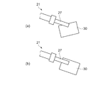
図13は、本実施形態のロボットの制御方法で用いられるロボットの第2のハンド部22の概略を示す斜視図である。第2のハンド部22は、手首部18と連続する基部26と指部27と平面部28を含んでいる。指部27はX方向に可動してワーク30を把持できる。そして、指部27の内側、すなわちX方向において他の指部27と対向する側の面には、滑りセンサー33が備えられている。
FIG. 13 is a perspective view schematically showing the
図14は、本実施形態のロボットの制御方法、すなわちワーク30の座標合せ工程を示す工程図である。本図において、図14((a)、(c)、(e))はワーク30をX方向から見た図であり、図14((b)、(d)、(f))はワーク30をY方向から見た図である。なお、ワーク30の座標系すなわちX方向、Y方向、Z方向については図3等に示す通りであり、本図及び後述する図15、図17では、図示を省略している。以下、工程順に説明する。
FIG. 14 is a process diagram illustrating a robot control method according to the present embodiment, that is, a coordinate alignment process of the
まず、上述の第1の実施形態のロボットの制御方法と同様に、座標系の粗調整を行う。そして、図14(a)、(b)に示すように、指部27をX方向に可動させて、ワーク30を把持する。かかる工程がワーク把持工程である。ロボット1でワーク30を把持する場合、部品箱等に収められたワーク30の上方から第2のハンド部22を接近させて把持することが一般的である。したがって、平面部28はワーク30の上方に位置することとなる。
First, as in the robot control method of the first embodiment described above, coarse adjustment of the coordinate system is performed. And as shown to Fig.14 (a), (b), the finger | toe
ここで本工程では、ワーク30を把持することのみを目的としているため、座標系の精度は粗くなっている。したがって、平面部28に対するワーク30の底面の平行度は確保されていない。また、上記の面は図4(b)に示すようなワーク30であれば、線に近くなる。さらに、図4(c)に示すようなワーク30であれば2点となる。すなわち、かかる2点の間に引かれる想定上の線が平面部28に対して平行にならない状態で、ワーク30は把持される。
Here, in this step, since the purpose is only to grip the
次に、反転工程として、図14(c)、(d)に示すように、平面部28が上方すなわち重力方向と反対の方向を向くようにロボット1を駆動する。すなわち、ワーク30と基部26の方向を逆転させ、ワーク30の下方に基部26及び平面部28が位置するようにする。かかる工程が反転工程である。なお、何らかの手法で、最初から図14(c)、(d)に示すように平面部28がワーク30の下方に位置するようにワーク30を把持できるのであれば、本工程は省略できる。
Next, as a reversal process, as shown in FIGS. 14C and 14D, the robot 1 is driven so that the
次に、図14(e)、(f)に示すように、第2のハンド部22の把持力、正確には指部27の把持力を低減して、上記ワーク30を平面部28上に落下させる。かかる工程が開放工程である。ここで、かかる落下は、滑りセンサー33で感知されるワーク30の落下速度すなわち滑り速度が所定の範囲内となるように行う。そのため、指部27を完全は開放しない。そのため、ワーク30は徐々に平面部28上に滑り落ちる。そしてワーク30は、上記の底面が平面部28に倣った状態で停止する。かかる状態は、ワーク30の形状が同一である限り、常に一定である。したがって、第2のハンド部22の座標系とワーク30の座標系とを一致させることができる。
Next, as shown in FIGS. 14 (e) and 14 (f), the gripping force of the
この後、第2のハンド部22の把持力を再度上昇させる再把持工程を実施することもできる。かかる工程は、ワーク30が停止した後、所定の時間経過後に実施することが好ましい。ワーク30の停止の判断は、滑りセンサー33を用いて行うことができる。
なお、本実施形態のロボットの制御方法は、滑りセンサー33を用いずに行うこともできる。すなわち、開放工程において指部27を完全に開放して、ワーク30を平面部28上に自由落下させることも可能である。
Thereafter, a re-gripping step of increasing the gripping force of the
Note that the robot control method of the present embodiment can be performed without using the
本実施形態のロボットの制御方法は、作業台32のような、ロボット1とは別途設けられた平面を用いることなく、ワーク30の座標系と第2のハンド部22の座標系を一致させられることに特徴がある。かかるロボットの制御方法であれば、ワーク30を作業台32上まで搬送する工程を省くことができるため、より一層効率的に上記の座標系を合せることができる。
The robot control method of the present embodiment can match the coordinate system of the
(第5の実施形態)
次に、本発明の第5の実施形態にかかるロボットの制御方法について説明する。本実施形態のロボットの制御方法は、上述の第4の実施形態のロボットの制御方法と類似している。すなわち、平面部28を有する第2のハンド部22を用いて、作業台32を用いずにワーク30の座標系を合せる制御方法である。そのため、本実施形態のロボットの制御方法で用いる第2のハンド部22は、第4の実施形態のロボットの制御方法で用いる第2のハンド部22と略同一であり、平面部28が可動部材である点が異なっている。そこで、工程図を用いて説明する。
(Fifth embodiment)
Next, a robot control method according to a fifth embodiment of the present invention will be described. The robot control method of the present embodiment is similar to the robot control method of the fourth embodiment described above. That is, this is a control method in which the coordinate system of the
図15は、本実施形態のロボットの制御方法、すなわちワーク30の座標合せ工程を示す工程図である。以下、各工程について述べる。まず、上述の第4の実施形態のロボットの制御方法と同様に、座標系の粗調整を行う。そして次に、ワーク把持工程として、図15(a)、(b)に示すように、指部27をX方向に可動させて、ワーク30を把持する。第4の実施形態におけるワーク把持工程と同様に、ワーク30は平面部28との間に間隔が生じるように、かつ、平面部28は下方に位置するように把持される。
FIG. 15 is a process diagram illustrating a robot control method according to the present embodiment, that is, a coordinate alignment process of the
そして次に、座標合せ工程として、図15(c)、(d)に示すように、平面部28を基部26側と反対の方向に駆動してワーク30に押し当てる。そして平面部28とワーク30の一方の面とを完全に対向させる。すなわち、そしてワーク30の底面を平面部28に倣わせて、第2のハンド部22の座標系とワーク30の座標系とを一致させる。本工程は、上述の再把持工程と同様に、滑りセンサー33を用いて、ワーク30が平面部28に押されて移動する速度が所定の範囲内となるように行う。そして、ワーク30の表面に指部27と摺動することによる傷等が発生しないように、把持力を下限しつつ行う。なお、ワーク30の底面を平面部28に倣わせた後に、第2のハンド部22の把持力を再度上昇させる再把持工程を実施しても良い。
Then, as a coordinate matching step, as shown in FIGS. 15C and 15D, the
本実施形態のロボットの制御方法であれば、上述の第4の実施形態のロボットの制御方法と同様に、第2のハンド部22の座標系とワーク30の座標系とを一致させることができる。そして本実施形態のロボットの制御方法は、ワーク30は固定したままで、平面部28を移動させて座標系を一致させることに特徴がある。そのため、重力を利用してワーク30を落下させる必要がなく、ワーク30を上側に向ける反転工程を実施せずに上述の座標系を一致させることができる。したがって、本実施形態のロボットの制御方法であれば、ワーク30を作業台32上まで搬送する工程と反転工程の双方を省くことができ、より一層効率的に上述の座標系を合せることができる。
With the robot control method of the present embodiment, the coordinate system of the
(第6の実施形態)
次に、本発明の第6の実施形態にかかるロボットの制御方法、及び本実施形態で用いられるロボットについて説明する。本実施形態のロボットの制御方法は、上述の第4、及び第5の実施形態のロボットの制御方法と類似している。すなわち、作業台32を用いずにワーク30の座標系を合せる制御方法である。しかし本実施形態のロボット制御方法は、上述の座標合せを、ワーク30を回転可能なように把持することが可能な第3のハンド部23を用いて行う点で、第4、及び第5の実施形態のロボットの制御方法と相違している。そこで本実施形態については、第3のハンド部23を示す図と工程図を用いて説明する。
(Sixth embodiment)
Next, a robot control method according to a sixth embodiment of the present invention and a robot used in the present embodiment will be described. The robot control method of this embodiment is similar to the robot control methods of the fourth and fifth embodiments described above. That is, this is a control method for matching the coordinate system of the
図16は、本実施形態のロボットの制御方法で用いられるロボットが有する第3のハンド部23の概略を示す斜視図である。第3のハンド部23は、手首部18と連続する基部26と指部27と平面部28を備えている。平面部28は、第2のハンド部22の該平面部と同様に可動部材である。指部27は、上述の第2のハンド部22の指部27と同様にX方向において可動であり、Y方向に位置するワーク30を把持できる。ただし、第3のハンド部23が備える指部27は、一すなわち2本のみである。そして、幅(Y方向の寸法)が、第2のハンド部22が備える指部27に比べて若干拡大されている。そして、指部27の内側、すなわちX方向において他の指部27と対向する側の面には、軸受け部34と回転センサー35が配置されている。回転センサー35は、図示するように、軸受け部34を囲むように複数個が配置されている。
FIG. 16 is a perspective view schematically illustrating the
図17は、本実施形態のロボットの制御方法を示す工程図、すなわち第3のハンド部23を用いて行うワーク30の座標合せ方法を示す工程図である。以下、各工程について述べる。まず、上述の第4、及び第5の実施形態のロボットの制御方方と同様に、座標系の粗調整を行う。そして次に、ワーク把持工程として、図17(a)、(b)に示すように、指部27をX方向に可動させて、ワーク30を把持する。
上述したように、指部27には軸受け部34が配置されているため、ワーク30は該軸受け部により把持される。そのため、把持力が不足する場合、ワーク30が軸受け部34を中心として回転する可能性がある。そこで本工程では、ワークの動きを回転センサー35で測定して、上記の回転が起こらないように把持力を調整する。
FIG. 17 is a process diagram illustrating a robot control method according to the present embodiment, that is, a process chart illustrating a coordinate alignment method of the
As described above, since the bearing
次に、座標合せ工程として、図17(c)、(d)に示すように、平面部28を上方すなわち基部26側と反対の方向に駆動する。そしてワーク30を、軸受け部34を中心として回転させる。本工程は、回転センサー35でワーク30の回転の状況を測定しつつ行う。すなわち、ワーク30が一定の速度で回転するように、平面部28の駆動速度を調整する。また、ワーク30がスムーズに回転するように把持力を調整する。そして、ワーク30の回転が停止したことが回転センサー35により確認された時点で、平面部28の駆動を停止する。以上の工程で、ワーク30の底面を平面部28に倣わせて、第3のハンド部23の座標系とワーク30の座標系とを一致させることができる。
Next, as a coordinate matching step, as shown in FIGS. 17C and 17D, the
本実施形態のロボットの制御方法は、上述の第5の実施形態のロボットの制御方法と同様に、反転工程を実施せずに第3のハンド部23の座標系とワーク30の座標系とを一致させることができる。また指部27で把持されたワーク30を摺動させず回転させるのみで上述の座標系を合せるため、指部27の全長(Z方向の寸法)を縮小できる。したがって、本実施形態のロボットの制御方法は、第3のハンド部23の形状に比較して、相対的に大型のワーク30を把持して座標系を合せることができるという特徴を有している。
The robot control method according to the present embodiment is similar to the robot control method according to the fifth embodiment described above, in which the coordinate system of the
本発明の実施の形態は、上述の各実施形態以外にも様々な変形例が考えられる。以下、変形例を挙げて説明する。 Various modifications of the embodiment of the present invention are possible in addition to the above-described embodiments. Hereinafter, a modification will be described.
(変形例1)
上述の第4の実施形態における開放工程では、指部27を完全に開くことなく、ワーク30を除去に落下させていた。しかし上述の工程では、指部27を完全に開放してワーク30を自由落下させることもできる。かかる方法であれば、滑りセンサー33を配置する必要がなく、第2のハンド部22の構成を簡略化できる。
また、滑りセンサー33に代えて、ばねで保持されたベアリング等を配置しても良い。かかる構成であれば、滑りセンサー33を用いることなくワーク30を徐々に落下させることができる。したがって、第2のハンド部22の構成、及びロボット1の制御装置(不図示)等を簡略化した上で、同様の効果を得ることができる。
(Modification 1)
In the opening process in the fourth embodiment described above, the
Moreover, it may replace with the
(変形例2)
上述の第5の実施形態、及び第6の実施形態において、平面部28は、該平面部が駆動される方向、すなわちZ方向に対して垂直であった。しかし、平面部28をZ方向に対して斜めに設定することも可能である。かかるロボットの制御方法であればワーク30がZ方向に対して所定の角度を有するように、座標系を合せることができる。したがって、ワーク30に対して第2のワーク36等を斜め方向から組み込むような作業を効率的に実施できる。
(Modification 2)
In the fifth embodiment and the sixth embodiment described above, the
(変形例3)
上述の第1〜第3の実施形態では、ワーク30を平面(平面としての作業台32)上に落下させていた。しかし、対象とするワーク30の底部が充分な面積を有する平面である場合、例えば図4(a)に示すワーク30をX方向に拡大した形状のワーク30である場合、作業台32(の上面)は、平面に限定する必要は無い。作業台32(の上面)が、規則的な凹凸を有する面であっても良い。なお、かかる「規則的な凹凸を有する面」とは、凸部(の頂点)が同一の平面に含まれる面を意味する。3点が接触すると平面が確定するため、上述のワーク30を対象とする場合、かかる上面を有する作業台32を用いても、ワーク30の座標系を合せることができる。
(Modification 3)
In the first to third embodiments described above, the
また同様に、上述の第4〜第6の実施形態において、第2のハンド部22が有する平面部28(のワーク30に対向する面)を、規則的な凹凸を有する面で構成することもできる。ワーク30の底部が充分な面積を有する平面である場合、かかる態様の平面部28を有する第2のハンド部22を用いても、ワーク30の座標系を合せることができる。
Similarly, in the above-described fourth to sixth embodiments, the flat surface portion 28 (the surface facing the workpiece 30) of the
1…ロボット、3…下側台座、4…上側台座、5…回転位置、6…回転位置、7…回転位置、8…回転位置、9…回転位置、10…回転位置、11…第1アーム、12…第2アーム、13…第3アーム、14…第4アーム、16…モーター、17…モーター、18…手首部、21…第1のハンド部、22…第2のハンド部、23…第3のハンド部、25…第5のハンド部、26…基部、27…指部、28…平面部、30…ワーク、31…接触センサー、32…平面としての作業台、33…滑りセンサー、34…軸受け部、35…回転センサー、36…第2のワーク。 DESCRIPTION OF SYMBOLS 1 ... Robot, 3 ... Lower base, 4 ... Upper base, 5 ... Rotation position, 6 ... Rotation position, 7 ... Rotation position, 8 ... Rotation position, 9 ... Rotation position, 10 ... Rotation position, 11 ... 1st arm , 12 ... 2nd arm, 13 ... 3rd arm, 14 ... 4th arm, 16 ... motor, 17 ... motor, 18 ... wrist part, 21 ... first hand part, 22 ... second hand part, 23 ... 3rd hand part, 25 ... 5th hand part, 26 ... Base part, 27 ... Finger part, 28 ... Plane part, 30 ... Workpiece, 31 ... Contact sensor, 32 ... Work table as plane, 33 ... Slip sensor, 34 ... bearing part, 35 ... rotation sensor, 36 ... second workpiece.
Claims (14)
前記ロボットは、対象物を把持可能なハンド部を有し、
前記ハンド部の前記対象物と接触する部分に、前記ハンド部に対する前記対象物の滑り量を検出する第1センサーを備え、
前記ハンド部により前記対象物を第1姿勢で把持する把持工程と、
前記ハンド部の把持力を前記第1センサーの検出値に基づいて低減することにより、前記第1姿勢とは異なる第2姿勢に前記対象物の姿勢を変更する開放工程と、
を含むことを特徴とするロボットの制御方法。 A robot control method,
The robot has a hand unit capable of gripping an object,
A portion of the hand unit that contacts the object includes a first sensor that detects a slip amount of the object with respect to the hand unit;
A gripping step of gripping the object in the first posture by the hand unit,
An opening step of changing the posture of the object to a second posture different from the first posture by reducing the gripping force of the hand unit based on a detection value of the first sensor ;
A method for controlling a robot, comprising:
前記第2姿勢である前記対象物を、前記把持力を増加することにより再把持する再把持工程を含むことを特徴とするロボットの制御方法。 A robot control method comprising: a re-gripping step of re-gripping the object in the second posture by increasing the grip force.
前記第2姿勢である前記対象物を再把持する再把持工程を含むことを特徴とするロボットの制御方法。 A robot control method comprising a re-gripping step of re-gripping the object in the second posture.
前記開放工程は、単位時間当たりの前記滑り量がしきい値以下となるように、前記ハンド部の把持力を調整しつつ実施する工程であることを特徴とするロボットの制御方法。 The robot control method according to any one of claims 1 to 3 ,
The robot control method according to claim 1, wherein the releasing step is a step that is performed while adjusting a gripping force of the hand unit so that the slip amount per unit time is equal to or less than a threshold value.
前記再把持工程は、前記開放工程を開始してから所定の時間が経過した後に実施される工程であることを特徴とするロボットの制御方法。 The robot control method according to any one of claims 2 to 4 , wherein:
The method of controlling a robot according to claim 1, wherein the re-gripping step is a step performed after a predetermined time has elapsed since the opening step was started.
前記開放工程は、作業台の載置面に前記対象物の一部を接触させる作業と、前記第2姿勢に前記対象物の姿勢を変更する作業と、を含む工程であることを特徴とするロボットの制御方法。 The releasing step includes a step of bringing a part of the object into contact with a mounting surface of a work table and a step of changing the posture of the object to the second posture. Robot control method.
前記第1センサーは、感圧導電性ゴムから得られる出力電圧を検出する滑りセンサーであることを特徴とするロボットの制御方法。 The robot control method according to claim 1, wherein the first sensor is a slip sensor that detects an output voltage obtained from a pressure-sensitive conductive rubber.
前記ロボットは、対象物を把持可能なハンド部を有し、 The robot has a hand unit capable of gripping an object,
前記ハンド部の前記対象物と接触する部分に、前記ハンド部に対する前記対象物の滑り量を検出する第1センサーを備え、 A portion of the hand unit that contacts the object includes a first sensor that detects a slip amount of the object with respect to the hand unit;
前記ハンド部により前記対象物を第1姿勢で把持する把持動作と、 A gripping operation of gripping the object in a first posture by the hand unit;
前記ハンド部の把持力を前記第1センサーの検出値に基づいて低減することにより、前記第1姿勢とは異なる第2姿勢に前記対象物の姿勢を変更する開放動作と、を行うことを特徴とするロボット。 An opening operation for changing the posture of the object to a second posture different from the first posture by reducing a gripping force of the hand unit based on a detection value of the first sensor. Robot.
前記第2姿勢である前記対象物を、前記把持力を増加することにより再把持する再把持動作を行うことを特徴とするロボット。 A robot performing a re-gripping operation of re-gripping the object in the second posture by increasing the grip force.
前記第2姿勢である前記対象物を、再度把持する再把持動作を行うことを特徴とするロボット。 A robot characterized by performing a re-gripping operation of gripping the object in the second posture again.
前記開放動作は、単位時間当たりの前記滑り量がしきい値以下となるように、前記ハンド部の把持力を調整しつつ実施する動作であることを特徴とするロボット。 The robot according to claim 1, wherein the opening operation is an operation performed while adjusting a gripping force of the hand unit so that the amount of slip per unit time is equal to or less than a threshold value.
前記再把持動作は、前記開放動作を開始してから所定の時間が経過した後に実施される動作であることを特徴とするロボット。 The robot according to claim 1, wherein the re-gripping operation is an operation performed after a predetermined time has elapsed since the opening operation was started.
前記開放動作は、作業台の載置面に前記対象物の一部を接触させ、前記第2姿勢に前記対象物の姿勢を変更する動作であることを特徴とするロボット。 The robot is characterized in that the opening operation is an operation of bringing a part of the object into contact with a mounting surface of a work table and changing the attitude of the object to the second attitude.
前記第1センサーは、感圧導電性ゴムから得られる出力電圧を検出する滑りセンサーであることを特徴とするロボット。 The robot according to claim 1, wherein the first sensor is a slip sensor that detects an output voltage obtained from a pressure-sensitive conductive rubber.
Priority Applications (2)
| Application Number | Priority Date | Filing Date | Title |
|---|---|---|---|
| JP2011073562A JP5810582B2 (en) | 2011-03-29 | 2011-03-29 | Robot control method and robot |
| US13/431,304 US8935004B2 (en) | 2011-03-29 | 2012-03-27 | Robot control method and robot |
Applications Claiming Priority (1)
| Application Number | Priority Date | Filing Date | Title |
|---|---|---|---|
| JP2011073562A JP5810582B2 (en) | 2011-03-29 | 2011-03-29 | Robot control method and robot |
Publications (3)
| Publication Number | Publication Date |
|---|---|
| JP2012206206A JP2012206206A (en) | 2012-10-25 |
| JP2012206206A5 JP2012206206A5 (en) | 2014-04-24 |
| JP5810582B2 true JP5810582B2 (en) | 2015-11-11 |
Family
ID=46928280
Family Applications (1)
| Application Number | Title | Priority Date | Filing Date |
|---|---|---|---|
| JP2011073562A Expired - Fee Related JP5810582B2 (en) | 2011-03-29 | 2011-03-29 | Robot control method and robot |
Country Status (2)
| Country | Link |
|---|---|
| US (1) | US8935004B2 (en) |
| JP (1) | JP5810582B2 (en) |
Cited By (1)
| Publication number | Priority date | Publication date | Assignee | Title |
|---|---|---|---|---|
| WO2021182702A1 (en) * | 2020-03-10 | 2021-09-16 | Samsung Electronics Co., Ltd. | Method and apparatus for manipulating a tool to control in-grasp sliding of an object held by the tool |
Families Citing this family (35)
| Publication number | Priority date | Publication date | Assignee | Title |
|---|---|---|---|---|
| DE102012013022A1 (en) * | 2012-06-29 | 2014-04-24 | Liebherr-Verzahntechnik Gmbh | Device for the automated handling of workpieces |
| JP5917380B2 (en) * | 2012-12-04 | 2016-05-11 | 川田工業株式会社 | Work positioning method using an articulated robot and work mounting method using an articulated robot using the work positioning method |
| US9095978B2 (en) * | 2012-12-07 | 2015-08-04 | GM Global Technology Operations LLC | Planning a grasp approach, position, and pre-grasp pose for a robotic grasper based on object, grasper, and environmental constraint data |
| US9102055B1 (en) | 2013-03-15 | 2015-08-11 | Industrial Perception, Inc. | Detection and reconstruction of an environment to facilitate robotic interaction with the environment |
| US9561590B1 (en) * | 2013-06-24 | 2017-02-07 | Redwood Robotics, Inc. | Distributed system for management and analytics of robotics devices |
| US9586320B2 (en) * | 2013-10-04 | 2017-03-07 | GM Global Technology Operations LLC | System and method for controlling a vision guided robot assembly |
| CN108621156B (en) | 2013-10-10 | 2021-08-03 | 精工爱普生株式会社 | Robot control device, robot system, robot, and robot control method |
| JP6354248B2 (en) * | 2014-03-26 | 2018-07-11 | セイコーエプソン株式会社 | Robot, robot system, control device, and control method |
| JP2015085479A (en) * | 2013-11-01 | 2015-05-07 | セイコーエプソン株式会社 | Robot, control device, robot system and robot control method |
| JP2015085480A (en) * | 2013-11-01 | 2015-05-07 | セイコーエプソン株式会社 | Robot, control device, robot system, robot control method and program |
| JP2015226968A (en) * | 2014-06-02 | 2015-12-17 | セイコーエプソン株式会社 | Robot, robot system, control unit and control method |
| JP6507492B2 (en) * | 2014-06-02 | 2019-05-08 | セイコーエプソン株式会社 | Robot, robot system and robot controller |
| US9272417B2 (en) * | 2014-07-16 | 2016-03-01 | Google Inc. | Real-time determination of object metrics for trajectory planning |
| US10011468B2 (en) | 2014-10-30 | 2018-07-03 | Cascade Corporation | Pivoting load-bearing assembly with force sensor |
| US10131525B2 (en) * | 2014-10-30 | 2018-11-20 | Cascade Corporation | Pivoting load-bearing assembly with force sensor |
| EP3029468B1 (en) | 2014-12-02 | 2019-10-30 | F.Hoffmann-La Roche Ag | Device for repositioning tubes in a tube rack |
| JP5927284B1 (en) * | 2014-12-22 | 2016-06-01 | ファナック株式会社 | A robot controller that detects contact force with a person and stops the robot |
| EP3238883B1 (en) | 2014-12-26 | 2020-12-09 | Kawasaki Jukogyo Kabushiki Kaisha | Robot |
| JP6468871B2 (en) * | 2015-02-03 | 2019-02-13 | キヤノン株式会社 | Robot hand control method and robot apparatus |
| JP2016179821A (en) * | 2015-03-23 | 2016-10-13 | セイコーエプソン株式会社 | Packing device, and packing method |
| US10329042B2 (en) | 2015-03-20 | 2019-06-25 | Seiko Epson Corporation | Packing apparatus and packing method |
| JP2016203280A (en) * | 2015-04-17 | 2016-12-08 | セイコーエプソン株式会社 | Robot and control device |
| DE102015213326B4 (en) * | 2015-07-16 | 2018-12-27 | Kuka Systems Gmbh | Method for handling a component |
| US9808936B2 (en) * | 2015-08-03 | 2017-11-07 | Massachusetts Institute Of Technology | Two-phase gripper to reorient and grasp |
| JP6212086B2 (en) * | 2015-08-31 | 2017-10-11 | ファナック株式会社 | Injection molding system |
| KR20180015774A (en) * | 2015-09-25 | 2018-02-14 | 두산로보틱스 주식회사 | Method and apparatus for controlling robot |
| DE102016109177B4 (en) | 2016-05-19 | 2018-01-25 | Festo Ag & Co. Kg | Gripper for holding an object |
| JP6534126B2 (en) * | 2016-11-22 | 2019-06-26 | パナソニックIpマネジメント株式会社 | Picking system and control method therefor |
| JP6426690B2 (en) * | 2016-12-22 | 2018-11-21 | ファナック株式会社 | Article picking system and method for picking out piled articles |
| CN109382826B (en) * | 2017-08-10 | 2023-05-16 | 精工爱普生株式会社 | Control device, robot, and robot system |
| FR3077755B1 (en) * | 2018-02-09 | 2020-02-14 | University Of Texas | DEVICE FOR PIVOTING AN OBJECT OF MICROMETRIC OR SUBMICROMETRIC DIMENSIONS |
| AT521039B1 (en) * | 2018-04-04 | 2019-10-15 | Trumpf Maschinen Austria Gmbh & Co Kg | Apparatus and method for monitoring relative movements |
| WO2020075589A1 (en) * | 2018-10-09 | 2020-04-16 | ソニー株式会社 | Information processing device, information processing method, and program |
| US11628561B2 (en) | 2019-08-19 | 2023-04-18 | The Hong Kong University Of Science And Technology | System and methods for robotic precision placement and insertion |
| WO2022119167A1 (en) * | 2020-12-03 | 2022-06-09 | 삼성전자주식회사 | Manipulator and control method therefor |
Family Cites Families (14)
| Publication number | Priority date | Publication date | Assignee | Title |
|---|---|---|---|---|
| JPS59107891A (en) * | 1982-12-13 | 1984-06-22 | 村田機械株式会社 | Robot hand |
| US5325468A (en) * | 1990-10-31 | 1994-06-28 | Sanyo Electric Co., Ltd. | Operation planning system for robot |
| JP3041404B2 (en) * | 1990-11-16 | 2000-05-15 | セイコーインスツルメンツ株式会社 | Auto sampling mechanism |
| JPH06285783A (en) * | 1992-06-15 | 1994-10-11 | Sanyo Electric Co Ltd | Automonously conveying device |
| JPH06297364A (en) | 1993-04-13 | 1994-10-25 | Daikin Ind Ltd | Positioning device |
| JPH07116973A (en) | 1993-10-26 | 1995-05-09 | Komatsu Ltd | Press brake robot device |
| JPH07155871A (en) | 1993-12-06 | 1995-06-20 | Komatsu Ltd | Work reclamping controller and work reclamper of robot |
| US6229552B1 (en) * | 1995-07-21 | 2001-05-08 | The Motion Factory | System and method for automatic motion generation |
| US6243621B1 (en) * | 1998-03-13 | 2001-06-05 | Fanuc Robotics North America, Inc. | Method of determining workpiece positions including coordinated motion |
| JP3688492B2 (en) * | 1999-01-26 | 2005-08-31 | 株式会社リコー | Part adsorption method and part adsorption device |
| JP3830477B2 (en) | 2003-09-04 | 2006-10-04 | ファナック株式会社 | Work transfer device |
| US20070231108A1 (en) * | 2006-04-04 | 2007-10-04 | Applied Materials, Inc. | Method and apparatus for transferring wafers |
| JP2009255191A (en) * | 2008-04-14 | 2009-11-05 | Canon Inc | Robot manipulator |
| EP2601504B1 (en) * | 2010-08-06 | 2020-12-30 | Siemens Healthcare Diagnostics Inc. | Methods and systems adapted to handle sticky sample containers |
-
2011
- 2011-03-29 JP JP2011073562A patent/JP5810582B2/en not_active Expired - Fee Related
-
2012
- 2012-03-27 US US13/431,304 patent/US8935004B2/en not_active Expired - Fee Related
Cited By (2)
| Publication number | Priority date | Publication date | Assignee | Title |
|---|---|---|---|---|
| WO2021182702A1 (en) * | 2020-03-10 | 2021-09-16 | Samsung Electronics Co., Ltd. | Method and apparatus for manipulating a tool to control in-grasp sliding of an object held by the tool |
| US11396103B2 (en) | 2020-03-10 | 2022-07-26 | Samsung Electronics Co., Ltd. | Method and apparatus for manipulating a tool to control in-grasp sliding of an object held by the tool |
Also Published As
| Publication number | Publication date |
|---|---|
| JP2012206206A (en) | 2012-10-25 |
| US20120253516A1 (en) | 2012-10-04 |
| US8935004B2 (en) | 2015-01-13 |
Similar Documents
| Publication | Publication Date | Title |
|---|---|---|
| JP5810582B2 (en) | Robot control method and robot | |
| JP6707485B2 (en) | Object handling device and calibration method thereof | |
| US10793378B2 (en) | Transfer apparatus and article taking-out method | |
| JP6545936B2 (en) | Parts transfer system and attitude adjustment device | |
| US20140277694A1 (en) | Robot system and method for producing to-be-processed material | |
| JPWO2018092254A1 (en) | Gripping force setting system, gripping force setting method, and gripping force estimation system | |
| JP2009255191A (en) | Robot manipulator | |
| JP6741222B2 (en) | Robot work transfer method and work transfer device | |
| EP2489482A2 (en) | Work Picking System | |
| JP2018158439A (en) | Object handling device, control device, and calibration method | |
| JP5913845B2 (en) | Conveying device and conveying method for plate member | |
| US20150343634A1 (en) | Robot, robot system, and control method | |
| WO2015136613A1 (en) | Robot hand | |
| EP3326037A1 (en) | System and method for determining tool offsets | |
| JP2013132726A (en) | Method for controlling robot, and robot | |
| US20160306340A1 (en) | Robot and control device | |
| JP2012024884A (en) | Gripping/conveying device | |
| KR101294250B1 (en) | Method and apparatus for calculating of gripping force of gripper | |
| JP2011073100A (en) | Picking method and hand device | |
| JP5807737B2 (en) | Hand device | |
| JP5704325B2 (en) | Hand device | |
| JP5827046B2 (en) | Plate member support device and support method, and plate member transport device | |
| JP2015074065A (en) | Robot and taking-out method | |
| JP7275830B2 (en) | Adsorber and moving adsorber | |
| JP5942720B2 (en) | State determination method, robot, control device, and program |
Legal Events
| Date | Code | Title | Description |
|---|---|---|---|
| A521 | Written amendment |
Free format text: JAPANESE INTERMEDIATE CODE: A523 Effective date: 20140311 |
|
| A621 | Written request for application examination |
Free format text: JAPANESE INTERMEDIATE CODE: A621 Effective date: 20140311 |
|
| RD04 | Notification of resignation of power of attorney |
Free format text: JAPANESE INTERMEDIATE CODE: A7424 Effective date: 20150106 |
|
| A977 | Report on retrieval |
Free format text: JAPANESE INTERMEDIATE CODE: A971007 Effective date: 20150109 |
|
| A131 | Notification of reasons for refusal |
Free format text: JAPANESE INTERMEDIATE CODE: A131 Effective date: 20150127 |
|
| A521 | Written amendment |
Free format text: JAPANESE INTERMEDIATE CODE: A523 Effective date: 20150324 |
|
| TRDD | Decision of grant or rejection written | ||
| A01 | Written decision to grant a patent or to grant a registration (utility model) |
Free format text: JAPANESE INTERMEDIATE CODE: A01 Effective date: 20150818 |
|
| A61 | First payment of annual fees (during grant procedure) |
Free format text: JAPANESE INTERMEDIATE CODE: A61 Effective date: 20150831 |
|
| R150 | Certificate of patent or registration of utility model |
Ref document number: 5810582 Country of ref document: JP Free format text: JAPANESE INTERMEDIATE CODE: R150 |
|
| S531 | Written request for registration of change of domicile |
Free format text: JAPANESE INTERMEDIATE CODE: R313531 |
|
| R350 | Written notification of registration of transfer |
Free format text: JAPANESE INTERMEDIATE CODE: R350 |
|
| LAPS | Cancellation because of no payment of annual fees |