以下、本発明の実施の形態に係る自動販売機について添付図面を参照して説明する。
Hereinafter, a vending machine according to an embodiment of the present invention will be described with reference to the accompanying drawings.
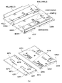
図1は本発明が対象とする自動販売機の一例である缶入り飲料,ペットボトル入り飲料を販売する自動販売機の側面図、図2は商品収納庫内を示す斜視図である。図に示すように、この自動販売機は、前面が開放した断熱筐体として形成された本体キャビネット1と、本体キャビネット1の前面に開閉可能に支持された外扉2とからなる。本体キャビネット1の商品収納庫の前面は開閉可能な断熱内扉3によって閉塞されている。前記本体キャビネット1は鋼板製の外箱の内側、すなわち、上壁1a,左右側壁1b,背壁1cおよび底壁1dにウレタンフォームからなる断熱パネルを配設して断熱筐体として構成されている。前記本体キャビネット1の断熱パネルで囲まれた商品収納庫内は断熱仕切板100(図2参照)により左右方向に複数の商品収納室A1,A2に区画され、当該商品収納室A1,A2には図2に示すように、左右方向に複数配列されるとともに上下方向に多段に配設された商品収容棚42を備えた商品収納ラック4がそれぞれ収納設置されている。この実施の形態では、商品収納室A1に1個の商品収納ラック4が収納設置され、商品収納室A2に2個の商品収納ラック4が収納設置されている。なお、図2では本体キャビネット1の上壁1aおよび後述する本体キャビネット1の下部に設けられた機械室8を省略している。
FIG. 1 is a side view of a vending machine that sells canned beverages and plastic bottled beverages as an example of a vending machine targeted by the present invention, and FIG. 2 is a perspective view showing the inside of a product storage. As shown in the figure, the vending machine includes a main body cabinet 1 formed as a heat-insulating housing whose front surface is open, and an outer door 2 supported on the front surface of the main body cabinet 1 so as to be openable and closable. The front surface of the product storage of the main body cabinet 1 is closed by a heat insulating inner door 3 that can be opened and closed. The main body cabinet 1 is configured as a heat insulating casing by disposing heat insulating panels made of urethane foam on the inner side of the outer box made of steel plate, that is, on the upper wall 1a, the left and right side walls 1b, the back wall 1c and the bottom wall 1d. . The inside of the product storage box surrounded by the heat insulation panel of the main body cabinet 1 is partitioned into a plurality of product storage rooms A1 and A2 in the left-right direction by a heat insulating partition plate 100 (see FIG. 2). As shown in FIG. 2, a plurality of product storage racks 4 including product storage shelves 42 that are arranged in the left-right direction and are arranged in multiple stages in the up-down direction are stored and installed. In this embodiment, one product storage rack 4 is stored and installed in the product storage room A1, and two product storage racks 4 are stored and installed in the product storage room A2. In FIG. 2, an upper wall 1a of the main body cabinet 1 and a machine room 8 provided in the lower portion of the main body cabinet 1 described later are omitted.
前記商品収納ラック4は、商品収容棚42が架設される左右のラック側板41を備えている。この左右のラック側板41は、矩形平板状の薄板鋼板製になり、この実施の形態では前後に分離された前方側ラック側板41F(以下、第1ラック側板41Fという)と後方側ラック側板41R(以下、第2ラック側板41Rという)からなる。この第1ラック側板41Fおよび第2ラック側板41Rに対応して前記商品収容棚42も後述する図9に示すように前後に分離されているが、ここでは総称して商品収納棚42という。そして、前後の商品収容棚42は前後に連なると共に、商品投入口44となる前方側が高く、商品搬出口45となる後方側が低くなるように所定の勾配をもって傾斜する態様で第1ラック側板41Fおよび第2ラック側板41Rに架設されている。また、前後の商品収容棚42に跨って前後方向に延在する左右一対のトップガイド40(図2では左サイドのトップガイド40が示され、右サイドのトップガイドはラック側板41に隠れて見えない)が配設されている。前後の商品収容棚42と左右一対のトップガイド40に囲まれた内部空間が複数の商品を横倒し姿勢で前後方向に一列に整列して収容する商品収容通路43(商品コラム)として構成され、この商品収容通路43(商品コラム)が上下多段(この実施の形態では10個の商品コラム)に形成されている。このように構成された商品収納ラック4が商品収納庫内に左右方向に複数並設されている。前記各商品収容通路43の商品搬出口45の近傍であって各商品収容通路43の上部、この実施の形態においては上段側の商品収容棚42の下面には当該商品収容通路43に収容された商品Gを一個ずつ切り出して搬出する商品搬出装置5が配設されている。そして、各段における商品収容棚42の後端部には、前記搬出通路46に突出する突出位置と、落下する商品Gにより押し開かれて搬出通路46から退避する退避位置との間を回動する姿勢制御板47が配備されている。この姿勢制御板47については後述するコイルばね474(図14参照)により搬出通路46に向けて突出するように付勢されており、搬出通路46を落下する商品Gにより押し開かれて搬出通路46から退避する際、当該商品Gの姿勢を横倒し姿勢に矯正するとともに当該商品Gの落下エネルギーを吸収してその落下速度を低減させる機能を有している。なお、商品収納ラック4は左右のラック側板41の上端を外側に向けて鋭角に折り曲げて形成されたフック片41F2,41R2(後述する図6参照)を、本体キャビネット1における商品収納庫の天井面に配設した前後方向に延在するレール部材Rに引っ掛けることにより商品収納庫内に設置されているものである。
The product storage rack 4 includes left and right rack side plates 41 on which product storage shelves 42 are installed. The left and right rack side plates 41 are made of a rectangular flat plate-shaped thin steel plate. In this embodiment, the front rack side plate 41F (hereinafter referred to as the first rack side plate 41F) and the rear rack side plate 41R separated from each other are separated. Hereinafter, it is referred to as a second rack side plate 41R). The product storage shelves 42 corresponding to the first rack side plate 41F and the second rack side plate 41R are also separated from each other as shown in FIG. 9 to be described later. The front and rear product storage shelves 42 are connected to the front and rear, and the first rack side plate 41F and the first rack side plate 41F are inclined with a predetermined gradient so that the front side serving as the product insertion port 44 is high and the rear side serving as the product outlet 45 is low. It is installed on the second rack side plate 41R. Further, a pair of left and right top guides 40 extending in the front-rear direction across the front and rear product storage shelves 42 (the left side top guide 40 is shown in FIG. 2, and the right side top guide is hidden by the rack side plate 41 and appears. Is not provided). An internal space surrounded by the front and rear product storage shelves 42 and a pair of left and right top guides 40 is configured as a product storage passage 43 (product column) that stores a plurality of products in a line-down posture in a line in the front-rear direction. The product storage passage 43 (product column) is formed in upper and lower multi-stages (10 product columns in this embodiment). A plurality of product storage racks 4 configured in this manner are arranged in the product storage case in the left-right direction. The product storage passages 43 are accommodated in the product storage passages 43 in the vicinity of the product outlets 45 and above the product storage passages 43, in this embodiment, on the lower surface of the upper product storage shelves 42. A product carry-out device 5 for cutting out and carrying out the products G one by one is provided. Then, at the rear end portion of the product storage shelf 42 in each stage, it is pivoted between a protruding position that protrudes into the carry-out passage 46 and a retreat position that is pushed open by the falling product G and retreats from the carry-out passage 46. A posture control plate 47 is provided. The attitude control plate 47 is urged so as to protrude toward the carry-out passage 46 by a coil spring 474 (see FIG. 14) described later, and is pushed open by the product G falling down the carry-out passage 46 to be carried out. When evacuating the product G, the product G has a function of lying down and correcting to a posture and absorbing the fall energy of the product G to reduce the fall speed. The product storage rack 4 has hook pieces 41F2 and 41R2 (see FIG. 6 to be described later) formed by bending the left and right rack side plates 41 outward at an acute angle, and the ceiling surface of the product storage in the main body cabinet 1. It is installed in the product storage by being hooked on the rail member R extending in the front-rear direction disposed on the product.
前記各商品収納ラック4に上下多段に配設された商品収容通路43の商品搬出口45は同一の鉛直線上に位置しており、前記商品搬出口45と商品収納庫背面(本体キャビネット1の背壁1c)との間には第2ラック側板41Rに係止固定された横断面コ字状の通路形成部材10が配設されており、当該通路形成部材10の内部空間が商品Gの落下する搬出通路46として形成されている。
The product outlets 45 of the product storage passages 43 arranged in the upper and lower stages in each of the product storage racks 4 are located on the same vertical line, and the product outlet 45 and the rear of the product storage (the back of the main body cabinet 1). Between the walls 1c), a passage forming member 10 having a U-shaped cross section that is locked and fixed to the second rack side plate 41R is disposed, and the internal space of the passage forming member 10 drops the product G. A carry-out passage 46 is formed.
前記通路形成部材10の下部には、搬出通路46と商品収納ラック4の下部に配された商品搬出シュート6とを連係するガイド部材20が係止されている。このガイド部材20は搬出通路46を略鉛直方向に落下する商品Gが商品搬出シュート6に向けて円滑に方向転換するようにガイドするとともに落下する商品Gの落下衝撃を緩和する機能を有している。前記商品搬出シュート6は商品収納ラック4の下部に前下がりの姿勢に配されるとともにその板面に複数の通気孔が穿孔されている。この商品搬出シュート6は前記搬出通路46と断熱内扉3に設けたフラッパ付きの商品搬出口31を介して外扉2の商品取出口21とを連係する。また、前記商品搬出シュート6の下部には、商品収納庫内を冷却若しくは加熱して商品収納ラック4に収容した商品Gをコールド若しくはホット状態に保存する冷却/加熱ユニット7が配設され、この冷却/加熱ユニット7の風洞7aに連ねて背面ダクト13が設けられている。さらに、本体キャビネット1の下部の機械室8には、冷却/加熱ユニット7の冷却ユニットと冷凍サイクルを形成する冷凍機コンデンシングユニット9が配設されている。
A guide member 20 that links the carry-out passage 46 and the product carry-out chute 6 disposed in the lower part of the product storage rack 4 is engaged with the lower portion of the passage forming member 10. The guide member 20 has a function of guiding the product G that falls in the carry-out passage 46 in a substantially vertical direction so as to smoothly change the direction toward the product carry-out chute 6 and alleviating the drop impact of the falling product G. Yes. The merchandise carry-out chute 6 is arranged in a downwardly lowered posture at the bottom of the merchandise storage rack 4 and a plurality of vent holes are perforated on the plate surface. The product carry-out chute 6 links the carry-out passage 46 and the product take-out port 21 of the outer door 2 via a product carry-out port 31 with a flapper provided in the heat insulating inner door 3. In addition, a cooling / heating unit 7 that cools or heats the inside of the product storage box and stores the product G stored in the product storage rack 4 in a cold or hot state is disposed below the product carry-out chute 6. A rear duct 13 is provided continuously to the wind tunnel 7 a of the cooling / heating unit 7. Furthermore, a refrigerator condensing unit 9 that forms a refrigeration cycle with the cooling unit of the cooling / heating unit 7 is disposed in the machine room 8 below the main body cabinet 1.
なお、外扉2の前面には、図示は省略するが、本体キャビネット1の庫内に収納した商品Gに対応した複数の商品見本を展示した商品展示室、購入する商品Gを指定する商品選択ボタン、代価としての硬貨を投入する硬貨投入口、代価としての紙幣を挿入する紙幣挿入口、釣銭硬貨若しくは返却指令により返却される硬貨を取り出すための硬貨返却口、釣銭若しくは投入硬貨の返却を指示する返却レバーなど、貨幣の投入により商品Gの自動販売に必要な部品が配設され、さらに、外扉2を本体キャビネット1に閉止鎖錠する扉ロック機構のハンドルなどが設けられている。
In addition, although illustration is abbreviate | omitted on the front surface of the outer door 2, the product display room which displayed the some product sample corresponding to the product G accommodated in the store | warehouse | chamber of the main body cabinet 1, and the product selection which designates the product G to purchase Button, coin insertion slot for inserting coins as a price, banknote insertion slot for inserting banknotes as a price, coin return slot for taking out change coins or coins returned in response to return instructions, instructing return of change or input coins Parts necessary for the automatic sale of the commodity G, such as a return lever, are disposed by the insertion of money, and a handle of a door lock mechanism for locking the outer door 2 to the main body cabinet 1 is provided.
前記本体キャビネット1の商品収納庫の背壁1cの上部には吸込みダクト14が設けられ、この実施の形態では商品収納ラック4ごとに吸込みダクト14が配設されている。この吸込みダクト14は商品収納室内の空気を吸い込み、次の図3で説明する側面ダクト15を介して背面ダクト13(冷却/加熱ユニット7)に戻すためのものである。以下、前記冷却/加熱ユニット7から吹き出された加熱若しくは冷却された空気の循環経路を形成するダクト構成について図3を用いて説明する。なお、図3は、図2から商品収納ラック4、商品搬出シュータ6、および風洞7a(冷却/加熱ユニット7)を除去した状態を示すものである。
A suction duct 14 is provided in the upper part of the back wall 1c of the product storage of the main body cabinet 1, and in this embodiment, the suction duct 14 is provided for each product storage rack 4. The suction duct 14 is for sucking air in the product storage chamber and returning it to the rear duct 13 (cooling / heating unit 7) via a side duct 15 described in FIG. Hereinafter, a duct configuration that forms a circulation path of heated or cooled air blown out from the cooling / heating unit 7 will be described with reference to FIG. FIG. 3 shows a state in which the product storage rack 4, the product carry-out shooter 6, and the wind tunnel 7a (cooling / heating unit 7) are removed from FIG.
図3において、13および14で再び背面ダクトおよび吸込みダクトを示し、15は側面ダクトである。前記背面ダクト13の前面(庫内側)には風洞7a(冷却/加熱ユニット7)に連通する開口131が形成され、背面ダクト14の下面には庫内に通じる吸込み口(不図示)が形成されている。前記側面ダクト15は、本体キャビネット1の左右側壁1b,1bおよび断熱仕切板100の商品収納室A2側の側面に沿わせて庫内底部から上部に向けて立上がるように敷設されている。側面ダクト15は庫内底部側においては背面ダクト13と連通し、上部側においては吸込みダクト14と連通するように構成されている。ここで、1個の商品収納ラック4が収納設置される比較的狭い商品収納室A1には側面ダクト15が一方の側面、この実施の形態では正面視左側の側壁1bに敷設され、2個の商品収納ラック4が収納設置される比較的広い商品収納室A2には側面ダクト15が左右側面、この実施の形態では正面視右側の側壁1bと断熱仕切板100の商品収納室A2側の側面に敷設されている。比較的広い商品収納室A2において側面ダクト15を左右側面に敷設しているのは、2個の商品収納ラック4に対応して庫内空気の循環経路を二つに分散させ、2個の商品収納ラック4に庫内空気を十分に循環させることができるようにするとともに2個の商品収納ラック4に収容された商品Gを効率良く冷却若しくは加熱するためである。このように、商品収納室A1には側面ダクト15に連通する一つの吸込みダクト14、商品収納室A2には左右の側面ダクト15,15にそれぞれ連通する二つの吸込みダクト14,14が敷設されている。なお、図3において、101〜104はそれぞれ板金により形成され、ウレタンフォームの断熱パネルからなる左右側壁1b,1b、背壁1c、断熱仕切板100の表面を覆って保護する保護部材であり、この保護部材101〜104に背面ダクト13、吸込みダクト14をねじで固着するように構成されている。
In FIG. 3, 13 and 14 again show the back duct and the suction duct, and 15 is a side duct. An opening 131 communicating with the wind tunnel 7a (cooling / heating unit 7) is formed on the front surface (inside the chamber) of the rear duct 13, and a suction port (not shown) leading to the interior is formed on the lower surface of the rear duct 14. ing. The side duct 15 is laid so as to rise from the bottom of the cabinet toward the top along the side walls of the main body cabinet 1 on the left and right side walls 1b and 1b and the side of the heat insulating partition plate 100 on the product storage room A2. The side duct 15 is configured to communicate with the rear duct 13 on the bottom side of the cabinet and to communicate with the suction duct 14 on the upper side. Here, a side duct 15 is laid on one side, in this embodiment, the left side wall 1b in the relatively narrow product storage room A1 in which one product storage rack 4 is stored and installed. In the relatively large product storage room A2 in which the product storage rack 4 is stored and installed, side ducts 15 are provided on the left and right side surfaces. In this embodiment, the side wall 1b on the right side in front view and the side surface on the product storage room A2 side of the heat insulating partition plate 100 are provided. It is laid. The reason why the side ducts 15 are laid on the left and right sides in the relatively large product storage room A2 is that the air circulation path in the cabinet is divided into two parts corresponding to the two product storage racks 4 and two products. This is to allow the air inside the storage rack 4 to be sufficiently circulated and to efficiently cool or heat the products G stored in the two product storage racks 4. As described above, the product storage room A1 is provided with one suction duct 14 that communicates with the side duct 15, and the product storage room A2 is provided with two suction ducts 14 and 14 that communicate with the left and right side ducts 15 and 15, respectively. Yes. In FIG. 3, reference numerals 101 to 104 are formed of sheet metal, and are protective members that cover and protect the surfaces of the left and right side walls 1b and 1b, the back wall 1c, and the heat insulating partition plate 100 made of a heat insulating panel of urethane foam. The rear duct 13 and the suction duct 14 are fixed to the protective members 101 to 104 with screws.
図3に示すダクト構成において、吸込みダクト14は、スラントラックの宿命である商品収納庫の背面側上部に形成されるデッドスペース(空きスペース)に敷設されている。すなわち、図1に示すように、商品収納庫に収納設置される商品収納ラック4には、商品投入口44となる前方側が高く、商品搬出口45となる後方側が低くなるように所定の勾配をもって傾斜する態様の商品収容棚42が架設されることから、商品収納庫の背面側上部には空きスペースが生じることとなるが、この実施の形態では吸込みダクト14は前記空きスペースに敷設されている。そして、側面ダクト15は庫内の左右サイドに配設されている。この構成により、従来装置では庫内背面に配設していた空気循環用ダクトを除去して庫内の前後方向領域を大きくすることが可能、つまり、商品収容通路43を長くすることが可能となるので、商品収容数を増やすことができるものである。
In the duct configuration shown in FIG. 3, the suction duct 14 is laid in a dead space (empty space) formed in the upper part on the back side of the commodity storage, which is the fate of the slang track. That is, as shown in FIG. 1, the product storage rack 4 stored and installed in the product storage has a predetermined slope so that the front side serving as the product inlet 44 is high and the rear side serving as the product outlet 45 is low. Since the product storage shelf 42 in an inclined manner is installed, an empty space is generated in the upper part on the back side of the product storage. In this embodiment, the suction duct 14 is laid in the empty space. . And the side surface duct 15 is arrange | positioned by the right-and-left side in a store | warehouse | chamber. With this configuration, it is possible to increase the front-rear direction area in the warehouse by removing the air circulation duct that has been arranged on the back of the warehouse in the conventional apparatus, that is, it is possible to lengthen the product accommodation passage 43. Therefore, the number of goods accommodated can be increased.
次に、商品収納ラック4の構成ついて図4を用いて説明する。図4は商品収納室A2(図2参照)に収納設置された正面視左側の商品収納ラック4を示している。この商品収納ラック4は、前後に分離された第1ラック側板41Fと第2ラック側板41Rからなる左右一対のラック側板41、前記第1ラック側板41Fと第2ラック側板41Rにそれぞれ架設される前方側商品収容棚42F(以下、これを第1商品収容棚42Fという)と後方側商品収容棚42R(以下、第2商品収容棚42Rという)、この第1商品収容棚42Fおよび第2商品収容棚42Rに跨って配設されるとともに第1商品収容棚42Fおよび第2商品収容棚42Rに連結された左右一組のトップガイド40(右サイドのトップガイドを40R、左サイドのトップガイドを40Lと称し、これらを総称する場合にはトップガイド40という)、前記第2ラック側板41Rに係止固定された横断面コ字状の通路形成部材10、この通路形成部材10の下端に係止されたガイド部材20などからなる。
Next, the configuration of the product storage rack 4 will be described with reference to FIG. FIG. 4 shows the product storage rack 4 on the left side when viewed from the front and stored in the product storage room A2 (see FIG. 2). The product storage rack 4 includes a pair of left and right rack side plates 41 composed of a first rack side plate 41F and a second rack side plate 41R separated in the front and rear directions, and a front mounted on the first rack side plate 41F and the second rack side plate 41R. Side product storage shelf 42F (hereinafter referred to as first product storage shelf 42F), rear product storage shelf 42R (hereinafter referred to as second product storage shelf 42R), the first product storage shelf 42F and the second product storage shelf A pair of left and right top guides 40 (the right side top guide is 40R and the left side top guide is 40L) arranged across the 42R and connected to the first product storage shelf 42F and the second product storage shelf 42R. And when these are collectively referred to as the top guide 40), the passage-forming member 10 having a U-shaped cross section that is locked and fixed to the second rack side plate 41R, It made of the guide member 20 which is engaged to the lower end of the road forming member 10.
前記左右のラック側板41は、図5に示すように、矩形平板状の薄板鋼板製の第1ラック側板41Fと第2ラック側板41Rからなる。第1ラック側板41Fに対して第2ラック側板41Rが長く形成されている点を除けば両者の構成は略同一であるので、第1ラック側板41Fについて説明し、第2ラック側板41Rについては参照符号を併記して説明は省略する。なお、図6に正面視右側のラック側板41を拡大して示し、図6も参照しつつ第1ラック側板41Fについて説明する。
As shown in FIG. 5, the left and right rack side plates 41 are composed of a first rack side plate 41 </ b> F and a second rack side plate 41 </ b> R made of a thin plate steel plate having a rectangular flat plate shape. Except for the fact that the second rack side plate 41R is formed longer than the first rack side plate 41F, the configuration of both is substantially the same. Therefore, the first rack side plate 41F will be described, and the second rack side plate 41R will be referred to. The description is omitted along with the reference numerals. 6 shows an enlarged view of the rack side plate 41 on the right side when viewed from the front, and the first rack side plate 41F will be described with reference to FIG.
第1ラック側板41Fは矩形平板状の薄板鋼板の前後および下縁を外方に折り曲げて補強フランジ41F1(41R1)が形成され、上縁には外方に鋭角に折り曲げた係合フック41F2(41R2)が形成されている。また、第1ラック側板41Fの板面には前後で対をなす係止孔41F3(41R3)が上下多段に形成され、前後一組の係止孔41F3(41R3)はそれぞれ段差を有している。前記係止孔41F3(41R3)は各段ごとに上下方向に離隔してそれぞれ2個形成されている。前記係止孔41F3(41R3)は商品収容棚42を架設するためのものであり、第1ラック側板41Fと第2ラック側板41Rを接近して配置した場合(奥行きの短い自動販売機の場合)には上段側の係止孔41F3(41R3)を利用し、第1ラック側板41Fと第2ラック側板41Rを離隔して配置した場合(奥行きの長い自動販売機の場合)には下段側の係止孔41F3(41R3)を利用するように構成されている。これは、第1ラック側板41Fと第2ラック側板41Rを接近或いは離隔して配置した場合にも当該第1ラック側板41Fと第2ラック側板41Rに架設される商品収容棚42の傾斜角度を一定に保つためである。なお、第2ラック側板41Rにおける後方側の係止孔41R3は前方側の係止孔41R3が円形であるのに対してL字状鉤形に形成されている。また、第2ラック側板41Rの後縁に形成された補強フランジ41R1には上下方向に複数のねじ穴(雌ねじ)41R4が形成されるとともに上部側に嵌合穴41R5が形成されている。
The first rack side plate 41F is formed with a reinforcing flange 41F1 (41R1) by bending the front and rear and lower edges of a rectangular flat plate steel plate outward, and the engaging hook 41F2 (41R2) bent outward at an acute angle at the upper edge. ) Is formed. Also, the plate surface of the first rack side plate 41F is formed with a plurality of upper and lower engaging holes 41F3 (41R3) in the front and rear, and the pair of front and rear engaging holes 41F3 (41R3) have steps. . Two locking holes 41F3 (41R3) are formed in each step so as to be spaced apart in the vertical direction. The locking hole 41F3 (41R3) is for erection of the product storage shelf 42, and the first rack side plate 41F and the second rack side plate 41R are arranged close to each other (in the case of a vending machine with a short depth). In the case where the first rack side plate 41F and the second rack side plate 41R are spaced apart from each other (in the case of a vending machine having a long depth), the upper side locking hole 41F3 (41R3) is used. It is comprised so that the stop hole 41F3 (41R3) may be utilized. This is because even when the first rack side plate 41F and the second rack side plate 41R are arranged close to or apart from each other, the inclination angle of the commodity storage shelf 42 installed on the first rack side plate 41F and the second rack side plate 41R is constant. This is to keep it in good condition. Note that the rear side locking hole 41R3 of the second rack side plate 41R is formed in an L-shaped bowl shape, whereas the front side locking hole 41R3 is circular. The reinforcing flange 41R1 formed at the rear edge of the second rack side plate 41R is formed with a plurality of screw holes (female screws) 41R4 in the vertical direction and a fitting hole 41R5 on the upper side.
第1ラック側板41Fの上縁に形成された係合フック41F2(41R2)は本体キャビネット1における商品収納庫の天井面に敷設したレール部材R,R(図4参照)に係合するものである。前記レール部材R,Rは左右対称に形成されており、図4の(a)に拡大して示すように、水平部R1、およびこの水平部R1の長手方向に沿って鉛直に折り曲げられた垂下部R2からなり、垂下部R2の下端から内側方向に折り返したフック部R3を備えている。前記レール部材R,Rは商品収納庫の天井面に設けたフレーム部材(不図示)に水平部R1がねじ止めされて前後方向に延在するように配設される。前記レール部材Rのフック部R3の先端は、前記係合フック41F2(41R2)が係合して摺動(スライド移動)する摺動面として形成され、この摺動面には、図7に示すように、ストッパ部R31,R32が形成されている。図7は正面視左側のレール部材Rを他方(右側)のレール部材R側から見た側面図である。前記ストッパ部R31,R32はレール部材Rの摺動面より一段高い凸状に形成されるとともにストッパ部R31,R32の間には係合フック41R2が丁度嵌まり込む寸法に定められている。前記レール部材Rのストッパ部R31,R32は、レール部材Rのフック部R3にラック側板41の係合フック41F2(41R2)を係合させた場合、商品収容庫内の所定位置に商品収納ラック4を収納設置する機能に加えて前後に分離された第1ラック側板41Fおよび第2ラック側板41Rが前後方向にずれて相互間の間隔がずれるのを防止する機能を有する。
Engagement hooks 41F2 (41R2) formed on the upper edge of the first rack side plate 41F are engaged with rail members R and R (see FIG. 4) laid on the ceiling surface of the product storage in the main body cabinet 1. . The rail members R, R are formed symmetrically, and as shown in an enlarged view in FIG. 4A, the hanging portion vertically bent along the horizontal portion R1 and the longitudinal direction of the horizontal portion R1. The hook portion R3 is formed of a portion R2 and is folded inward from the lower end of the hanging portion R2. The rail members R, R are arranged such that a horizontal member R1 is screwed to a frame member (not shown) provided on the ceiling surface of the product storage and extends in the front-rear direction. The tip of the hook portion R3 of the rail member R is formed as a sliding surface on which the engaging hook 41F2 (41R2) engages and slides (slides). This sliding surface is shown in FIG. As described above, stopper portions R31 and R32 are formed. FIG. 7 is a side view of the left side rail member R viewed from the other (right side) rail member R side. The stopper portions R31 and R32 are formed in a convex shape that is one step higher than the sliding surface of the rail member R, and the size of the engaging hook 41R2 is just fitted between the stopper portions R31 and R32. The stoppers R31 and R32 of the rail member R are arranged so that the product storage rack 4 is placed at a predetermined position in the product storage when the engagement hook 41F2 (41R2) of the rack side plate 41 is engaged with the hook portion R3 of the rail member R. In addition to the function of storing and installing the first rack side plate 41F and the second rack side plate 41R separated in the front-rear direction, the first rack side plate 41R and the second rack side plate 41R are prevented from shifting in the front-rear direction.
また、第1ラック側板41Fの下端後方側には板金により形成された位置決めガイド41G(図5,図6参照)が固着されている。この位置決めガイド41Gは、図8に示すように、短冊状の基板部41G1の左右両端を上方に向けて折り曲げてなる橋渡し部41G2の前端を互いに内方をむくように折り曲げた係止片41G3にねじ穴(雌ねじ)41G31が形成されている。前記基板部41G1の後端側は左右端縁を切欠いて左右の橋渡し部41G2間の寸法よりも短く形成されるとともにその後端縁には中空円筒形状(カール状)に丸めたカール状補強部41G11が形成されている。このカール状補強部41G11の左右方向の長さは左右に対向配置される第2ラック側板41Rの間の寸法より僅かに短く、左右に対向配置される第2ラック側板41Rの間に丁度嵌まり込む長さに形成されている。前記位置決めガイド41Gは、図6に示すように、左右の係止片41G3を第1ラック側板41Fの後縁に形成した補強フランジ41F1に沿わせた上で基板41G1の後端縁に形成したカール状補強部41G11を第2ラック側板41Rの間に嵌め込む。この際、基板41G1の後端側の左右の切欠きが第2ラック側板41Rの前端縁に形成した補強フランジ41R1の外壁と第2ラック側板41Rの内壁に沿うようになる。このように、位置決めガイド41Gを第1ラック側板41Fおよび第2ラック側板41Rに跨るように配設した状態で第1ラック側板41Fの後縁に形成した補強フランジ41F1を介して係止片41G3のねじ穴(雌ねじ)41G31にねじS1(図6参照)を螺合させると、位置決めガイド41Gは第1ラック側板41Fおよび第2ラック側板41Rに跨って両者を連結する。したがって、この位置決めガイド41Gは、左右に対向配置されるラック側板41F,41Rの間隔を所定の間隔に維持するとともに前後に分離された第1ラック側板41Fおよび第2ラック側板41Rが左右方向にずれるのを防止する機能を有する。
In addition, a positioning guide 41G (see FIGS. 5 and 6) formed of sheet metal is fixed to the rear side of the lower end of the first rack side plate 41F. As shown in FIG. 8, the positioning guide 41G is formed on a locking piece 41G3 which is bent so that the front ends of the bridging portion 41G2 formed by bending the left and right ends of the strip-shaped substrate portion 41G1 upward are peeled inward. A screw hole (female screw) 41G31 is formed. The rear end side of the substrate portion 41G1 is formed by cutting the left and right end edges shorter than the size between the left and right bridging portions 41G2, and the rear end edge is curled reinforcing portion 41G11 rounded into a hollow cylindrical shape (curl shape). Is formed. The length of the curl-shaped reinforcing portion 41G11 in the left-right direction is slightly shorter than the dimension between the second rack side plates 41R arranged opposite to the left and right, and just fits between the second rack side plates 41R arranged opposite to the left and right. It is formed in the length to insert. As shown in FIG. 6, the positioning guide 41G has a curl formed on the rear end edge of the substrate 41G1 after the left and right locking pieces 41G3 are aligned with the reinforcing flange 41F1 formed on the rear edge of the first rack side plate 41F. The shape reinforcing portion 41G11 is fitted between the second rack side plates 41R. At this time, the left and right cutouts on the rear end side of the board 41G1 are along the outer wall of the reinforcing flange 41R1 formed at the front end edge of the second rack side plate 41R and the inner wall of the second rack side plate 41R. As described above, the positioning guide 41G is disposed so as to straddle the first rack side plate 41F and the second rack side plate 41R, and the locking piece 41G3 is interposed via the reinforcing flange 41F1 formed at the rear edge of the first rack side plate 41F. When the screw S1 (see FIG. 6) is screwed into the screw hole (female screw) 41G31, the positioning guide 41G connects both of them across the first rack side plate 41F and the second rack side plate 41R. Therefore, the positioning guide 41G maintains the spacing between the rack side plates 41F and 41R opposed to the left and right at a predetermined interval, and the first rack side plate 41F and the second rack side plate 41R separated front and rear are shifted in the left and right direction. It has a function to prevent this.
次に、図9は、前記第1ラック側板41F,第2ラック側板41Rにそれぞれ架設される第1商品収容棚42F,第2商品収容棚42Rと、この第1商品収容棚42F,第2商品収容棚42Rに左右一組のトップガイド40を組み付けた状態を示している。前記左右一対のトップガイド40は右サイドに位置するトップガイド40Rと右サイドに位置するトップガイド40Lとからなり、それぞれ第1商品収容棚42F,第2商品収容棚42Rに跨って配設されるとともに前後方向に延在する態様で商品収容通路43を形成する。ここで、殆どの場合、右サイドに位置する固定トップガイド40Rに対して左サイドに位置する可動トップガイド40Lを接近・離隔させることにより商品収容通路43を商品の長さ(幅)に応じた通路幅に設定するように構成されており、以下では右サイドに位置する固定トップガイド40Rを固定トップガイド40R、左サイドに位置する可動トップガイド40Lを可動トップガイド40Lという。なお、図9では第2商品収容棚42Rの後端部に配備される姿勢制御板47は取外されている。
Next, FIG. 9 shows a first product storage shelf 42F and a second product storage shelf 42R installed on the first rack side plate 41F and the second rack side plate 41R, respectively, and the first product storage shelf 42F and the second product. A state in which a pair of left and right top guides 40 is assembled to the storage shelf 42R is shown. The pair of left and right top guides 40 includes a top guide 40R positioned on the right side and a top guide 40L positioned on the right side, and are disposed across the first product storage shelf 42F and the second product storage shelf 42R, respectively. At the same time, the product accommodating passage 43 is formed in a manner extending in the front-rear direction. Here, in most cases, the commodity receiving passage 43 is made to correspond to the length (width) of the commodity by moving the movable top guide 40L located on the left side closer to or away from the fixed top guide 40R located on the right side. In the following, the fixed top guide 40R located on the right side is referred to as a fixed top guide 40R, and the movable top guide 40L located on the left side is referred to as a movable top guide 40L. In FIG. 9, the attitude control plate 47 provided at the rear end of the second commodity storage shelf 42R is removed.
前記第1商品収容棚42Fと第2商品収容棚42Rについて図10をも参照しつつ説明する。第1商品収容棚42Fと第2商品収容棚42Rはそれぞれ矩形鋼板製になり、第1商品収容棚42Fと第2商品収容棚42Rと共通の部分は第1商品収容棚42Fについて説明し、第2商品収容棚42Rについては参照符号を併記して説明は省略する。
The first product storage shelf 42F and the second product storage shelf 42R will be described with reference to FIG. The first product storage shelf 42F and the second product storage shelf 42R are each made of a rectangular steel plate, and the common part between the first product storage shelf 42F and the second product storage shelf 42R describes the first product storage shelf 42F. The two commodity storage shelves 42 </ b> R are described with reference numerals and the description thereof is omitted.
前記第1商品収容棚42F(42R)は、図10に示すように、その左右側縁から下方に折り曲げられたフランジ42FA,42FB(42RA,42RB)を形成して強度アップが図られている(図9では左側縁に形成されたフランジ42FA(42RA)は隠れて見えないが、フランジ42RAについては後述する図25の(b)を参照)。前記フランジ42FA,42FB(42RA,42RB)にはねじ穴(雌ねじ)42FA1,42FB1(42RA1,42RB1)がそれぞれ形成されている。第1商品収容棚42F(42R)の前端には中空円筒形状(カール状)に丸めた支持軸42F1(42R1)が形成され、支持軸42F1(42R1)の左右両端はそれぞれフランジ42FA,42FB(42RA,42RB)よりも外方に突出するように形成されている。また、第1商品収容棚42Fの後端には中空円筒形状(カール状)に丸めた支持軸42F2が形成され、支持軸42F2の左右両端はそれぞれフランジ42FA,42FBよりも外方に突出するように形成されている。さらに、第1商品収容棚42Fの板面の前方寄りには左右方向に延在する太幅の操作孔42F3および太幅のスリットの後方端に細幅のスリットが連通したスライド係合孔42F4が穿設され、第1商品収容棚42Fの板面の後方寄りには太幅のスリットの前方端に細幅のスリットが連通したスライド係合孔42F5が穿設されている。
As shown in FIG. 10, the first commodity storage shelf 42F (42R) is formed with flanges 42FA and 42FB (42RA and 42RB) bent downward from the left and right side edges to increase the strength ( In FIG. 9, the flange 42FA (42RA) formed on the left edge is hidden and cannot be seen, but the flange 42RA is described later with reference to FIG. Screw holes (female screws) 42FA1, 42FB1 (42RA1, 42RB1) are formed in the flanges 42FA, 42FB (42RA, 42RB), respectively. A support shaft 42F1 (42R1) rounded into a hollow cylindrical shape (curl shape) is formed at the front end of the first commodity storage shelf 42F (42R), and the left and right ends of the support shaft 42F1 (42R1) are flanges 42FA and 42FB (42RA), respectively. , 42RB) so as to protrude outward. Further, a support shaft 42F2 that is rounded into a hollow cylindrical shape (curl shape) is formed at the rear end of the first commodity storage shelf 42F, and the left and right ends of the support shaft 42F2 protrude outward from the flanges 42FA and 42FB, respectively. Is formed. Further, a wide operation hole 42F3 extending in the left-right direction and a slide engagement hole 42F4 in which a narrow slit is communicated with the rear end of the wide slit are located near the front of the plate surface of the first commodity storage shelf 42F. A slide engagement hole 42F5 in which a narrow slit is communicated with a front end of a wide slit is formed near the rear of the plate surface of the first commodity storage shelf 42F.
前記第2商品収容棚42Rの後端には折り曲げにより形成された溝状の保持部42R2(後述する図25も参照)が設けられている。この保持部42R2は後述する商品搬出装置5を保持するものである。前記保持部42R2の左右両端はそれぞれフランジ42RA,42RBよりも外方に突出するL字状の支持片42R21,42R21として形成されている。また、第2商品収容棚42Rの板面には前後方向に延在するスリット状の設定溝42RHが左右方向に複数穿設されている。このスリット状の設定溝42RHは前後に対をなすように形成されている。さらに、第2商品収容棚42Rの板面の前方寄りには、背面に向けて押し出し形成されたアーチ状の嵌合突起42R3,42R4が形成されている。この嵌合突起42R3,42R4は中央部分(アーチ部分)が第2商品収容棚42Rの背面から浮き上がり、後述する図20商品搬出装置5の基板50の係止爪501,502の先端が通過可能な貫通穴として形成されている。そして、第2商品収容棚42Rの板面の後端には、後述する図22に示す商品搬出装置5の第1ストッパ56のロック部材566における弓状の突起567および左右のガイド突起568,568が貫通する3つの逃げ穴42R5が形成されている。
A groove-shaped holding portion 42R2 (see also FIG. 25 described later) formed by bending is provided at the rear end of the second commodity storage shelf 42R. This holding part 42R2 holds the commodity carry-out device 5 described later. The left and right ends of the holding portion 42R2 are formed as L-shaped support pieces 42R21 and 42R21 that protrude outward from the flanges 42RA and 42RB, respectively. In addition, a plurality of slit-shaped setting grooves 42RH extending in the front-rear direction are formed in the left-right direction on the plate surface of the second product storage shelf 42R. The slit-shaped setting groove 42RH is formed to make a pair in the front-rear direction. Furthermore, arch-shaped fitting protrusions 42R3 and 42R4 are formed on the front side of the plate surface of the second product storage shelf 42R so as to be extruded toward the back surface. The center portions (arch portions) of the fitting protrusions 42R3 and 42R4 are lifted from the back surface of the second product storage shelf 42R, and the tips of the locking claws 501 and 502 of the substrate 50 of the product unloading device 5 shown in FIG. It is formed as a through hole. At the rear end of the plate surface of the second product storage shelf 42R, an arcuate projection 567 and left and right guide projections 568 and 568 on the lock member 566 of the first stopper 56 of the product carry-out device 5 shown in FIG. Three escape holes 42R5 are formed through which.
前記第1商品収容棚42Fは、第1ラック側板41Fに次のように架設される。すなわち、第1商品収容棚42Fにおける左右に突出する前後の支持軸42F1,42F2を第1ラック側板41Fの板面に形成した前後で対をなす係止孔41F3,41F3にそれぞれ嵌め込む。これにより第1商品収容棚42Fが第1ラック側板41Fに架設される。同様に第2商品収容棚42Rは支持軸42R1および支持片42R21を、第2ラック側板41Rの係止孔41R3,41R3にそれぞれ嵌め込む。これにより第2商品収容棚42Rが第2ラック側板41Rに架設される。そして、第1商品収容棚42Fおよび第2商品収容棚42Fのそれぞれのフランジ42FA,42FB(42RA,42RB)に形成されたねじ穴(雌ねじ)42FA1,42FB1(42RA1,42RB1)に第1ラック側板41F,第2ラック側板41Rを介してねじが螺合される。この場合、この実施の形態においては、上下多段の第1商品収容棚42F,第2商品収容棚42Rのうちの上段,中段,下段に位置する第1商品収容棚42F,第2商品収容棚42Rのみをねじ止めするように構成されている。これにより上下方向に多段の第1商品収容棚42F,第2商品収容棚42Rの全てをねじ止めする場合に対して組立工数を削減することができる。
The first product storage shelf 42F is installed on the first rack side plate 41F as follows. That is, the front and rear support shafts 42F1 and 42F2 protruding left and right in the first product storage shelf 42F are respectively fitted in the locking holes 41F3 and 41F3 that form a pair before and after forming on the plate surface of the first rack side plate 41F. Thus, the first product storage shelf 42F is installed on the first rack side plate 41F. Similarly, the second product storage shelf 42R fits the support shaft 42R1 and the support piece 42R21 into the locking holes 41R3 and 41R3 of the second rack side plate 41R, respectively. Thus, the second product storage shelf 42R is installed on the second rack side plate 41R. The first rack side plate 41F is inserted into the screw holes (female screws) 42FA1, 42FB1 (42RA1, 42RB1) formed in the flanges 42FA, 42FB (42RA, 42RB) of the first product storage shelf 42F and the second product storage shelf 42F. , Screws are screwed through the second rack side plate 41R. In this case, in this embodiment, the first product storage shelves 42F and the second product storage shelves 42R located in the upper, middle, and lower stages of the first and second multi-stage first product storage shelves 42F and second product storage shelves 42R. It is configured to screw only. As a result, the number of assembling steps can be reduced as compared with the case where all of the first product storage shelves 42F and the second product storage shelves 42R are screwed in the vertical direction.
次に、図11は固定トップガイド40Rを示し、(a)は左斜め上方から見た斜視図、(b)は左斜め下方から見た斜視図である。この固定トップガイド40Rは、L字状に折り曲げた薄板鋼板になり、第1商品収容棚42F,第2商品収容棚42Rの板面に平行な商品載置部40R1と、第1商品収容棚42F,第2商品収容棚42Rの板面に鉛直な側壁部40R2からなる。前記商品載置部40R1の前端(図示状態では右斜め前方端)には第1商品収容棚42Fの中空円筒形状(カール状)の支持軸42F1よりも一回り大きなカール状の嵌合部40R3が形成されている。この嵌合部40R3は第1商品収容棚42Fの中空円筒形状(カール状)の支持軸42F1の外周の4分の3を包み込むような4分の3円環状に形成され、前記支持軸42F1に嵌合した状態で当該支持軸42F1に遊嵌されて左右にスライド移動自在である。また、商品載置部40R1の板面における前方寄りには背面側に向けて突出するフック片40R11が切り起こしにより形成されている。さらに、商品載置部40R1の板面における後方寄りには背面側に向けて突出する前後一対の係合爪40R12,40R12が切り起こしにより形成されている。この係合爪40R12,40R12は、側面から見た場合略V字状に形成されている。この前後一対の係合爪40R12,40R12は前述した第2商品収容棚42Rの板面に形成した前後一対の設定溝42RH,42RHに係合・離脱可能である。
Next, FIG. 11 shows the fixed top guide 40R, (a) is a perspective view seen from the upper left and (b) is a perspective view seen from the lower left. The fixed top guide 40R is a thin steel plate bent in an L shape, and the product placement section 40R1 parallel to the plate surfaces of the first product storage shelf 42F and the second product storage shelf 42R, and the first product storage shelf 42F. The side wall portion 40R2 is perpendicular to the plate surface of the second product storage shelf 42R. A curled fitting portion 40R3 that is slightly larger than the hollow cylindrical (curled) support shaft 42F1 of the first product storage shelf 42F is provided at the front end (in the illustrated state, right oblique front end) of the product placement portion 40R1. Is formed. The fitting portion 40R3 is formed in a three-quarter ring shape so as to wrap around three-fourths of the outer periphery of the hollow cylindrical (curled) support shaft 42F1 of the first commodity storage shelf 42F, and is attached to the support shaft 42F1. In the fitted state, it is loosely fitted to the support shaft 42F1 and is slidable to the left and right. Further, a hook piece 40R11 that protrudes toward the back side is formed by cutting and raising the front side of the plate surface of the product placement portion 40R1. Furthermore, a pair of front and rear engaging claws 40R12 and 40R12 projecting toward the back side are formed by cutting and raising near the rear side of the plate surface of the product placing portion 40R1. The engaging claws 40R12 and 40R12 are formed in a substantially V shape when viewed from the side. The pair of front and rear engagement claws 40R12 and 40R12 can be engaged and disengaged with the pair of front and rear setting grooves 42RH and 42RH formed on the plate surface of the second product storage shelf 42R.
次に、図12は可動トップガイド40Lを示し、(a)は右斜め上方から見た斜視図、(b)は右斜め下方から見た斜視図である。この可動トップガイド40Lは、L字状に折り曲げた薄板鋼板になり、第1商品収容棚42F,第2商品収容棚42Rの板面に平行な商品載置部40L1と、第1商品収容棚42F,第2商品収容棚42Rの板面に鉛直な規制部40L2からなる。前記商品載置部40L1の前端(図示状態では左斜め前方端)には第1商品収容棚42Fの中空円筒形状(カール状)の支持軸42F1よりも二段階大きく、かつ、前述した固定トップガイド40Rのカール状の嵌合部40R3よりも一回り大きなカール状の嵌合部40L3が形成されている。この嵌合部40L3は第1商品収容棚42Fの中空円筒形状(カール状)の支持軸42F1の外周の4分の3を包み込むような4分の3円環状に形成され、前記支持軸42F1に嵌合した状態で当該支持軸42F1に遊嵌されて左右にスライド移動自在であり、さらに前述した固定トップガイド40Rのカール状の嵌合部40R3に遊嵌されるように形成されている。また、商品載置部40L1の板面における中間部より前方側には背面側に向けて突出するフック片40L11が切り起こしにより形成されるともに後方寄りには背面側に向けて突出する前後一対の係合爪40L12,40L12が切り起こしにより形成されている。この係合爪40L12,40L12は、側面から見た場合略V字状に形成されている。この前後一対の係合爪40L12,40L12は前述した第2商品収容棚42Rの板面に形成した前後一対の設定溝42RH,42RHに係合・離脱可能である。
Next, FIG. 12 shows the movable top guide 40L, (a) is a perspective view seen from the upper right side, and (b) is a perspective view seen from the lower right side. The movable top guide 40L is a thin steel plate bent into an L shape, and the product placement section 40L1 parallel to the plate surfaces of the first product storage shelf 42F and the second product storage shelf 42R, and the first product storage shelf 42F. , And a restriction portion 40L2 perpendicular to the plate surface of the second commodity storage shelf 42R. The front end (the left oblique front end in the illustrated state) of the product placement portion 40L1 is two steps larger than the hollow cylindrical (curled) support shaft 42F1 of the first product storage shelf 42F, and the above-described fixed top guide. A curl-like fitting portion 40L3 that is slightly larger than the 40R-curled fitting portion 40R3 is formed. The fitting portion 40L3 is formed in a three-quarter ring shape so as to wrap around three-fourths of the outer periphery of the hollow cylindrical (curled) support shaft 42F1 of the first commodity storage shelf 42F, and is attached to the support shaft 42F1. In the fitted state, it is loosely fitted to the support shaft 42F1 and is slidable to the left and right, and is further loosely fitted to the curled fitting portion 40R3 of the fixed top guide 40R described above. Also, a hook piece 40L11 that protrudes toward the back side is formed on the front side of the intermediate portion of the plate surface of the product placement portion 40L1 by cutting and raising, and a pair of front and rear that protrudes toward the back side near the rear side. The engaging claws 40L12 and 40L12 are formed by cutting and raising. The engaging claws 40L12, 40L12 are formed in a substantially V shape when viewed from the side. The pair of front and rear engaging claws 40L12 and 40L12 can be engaged and disengaged with the pair of front and rear setting grooves 42RH and 42RH formed on the plate surface of the second commodity storage shelf 42R.
前記固定トップガイド40Rは、第1商品収容棚42Fおよび第2商品収容棚42Rに次のようにして組付けられる。すなわち、第1商品収容棚42Fおよび第2商品収容棚42Rの上方から固定トップガイド40Rの商品載置部40R1に形成したフック片40R11を第1商品収容棚42Fの板面に形成したスライド係合孔42F4の太幅スリットに対峙させて挿通させる。この状態では固定トップガイド40Rの嵌合部40R3は第1商品収容棚42Fの支持軸42F1よりも前方に位置している。この後、固定トップガイド40Rを後方側に移動させると、固定トップガイド40Rの嵌合部40R3が第1商品収容棚42Fの支持軸42F1の外周を包み込むように嵌合する。このとき、フック片40R11の鉛直部分はスライド係合孔42F4の太幅スリット内を後方に移動した後、細幅スリットの開放面に合致する位置に達し、フック片40R11の水平部分が太幅スリットの後方側に位置している。この状態で固定トップガイド40Rから手を離すと固定トップガイド40Rは、係合爪40R12が第2商品収容棚42Rの板面に当接して第1商品収容棚42F,第2商品収容棚42Rから浮き上がった状態となり、また、フック片40R11の水平部分は第1商品収容棚42Fの背面から離隔している。
The fixed top guide 40R is assembled to the first product storage shelf 42F and the second product storage shelf 42R as follows. That is, the slide engagement which formed the hook piece 40R11 formed in the product mounting part 40R1 of the fixed top guide 40R from the upper side of the first product storage shelf 42F and the second product storage shelf 42R on the plate surface of the first product storage shelf 42F. It is made to pass through the wide slit of the hole 42F4. In this state, the fitting portion 40R3 of the fixed top guide 40R is positioned in front of the support shaft 42F1 of the first product storage shelf 42F. Thereafter, when the fixed top guide 40R is moved rearward, the fitting portion 40R3 of the fixed top guide 40R is fitted so as to wrap around the outer periphery of the support shaft 42F1 of the first commodity storage shelf 42F. At this time, the vertical portion of the hook piece 40R11 moves rearwardly in the wide slit of the slide engagement hole 42F4 and then reaches a position that matches the open surface of the narrow slit, and the horizontal portion of the hook piece 40R11 is the wide slit. It is located on the back side. When the hand is released from the fixed top guide 40R in this state, the fixed claw 40R12 comes into contact with the plate surface of the second product storage shelf 42R from the first product storage shelf 42F and the second product storage shelf 42R. It is in a floating state, and the horizontal portion of the hook piece 40R11 is separated from the back surface of the first commodity storage shelf 42F.
前述した状態から第1商品収容棚42Fの背面側に手を回し、手の平を上にした状態で親指を嵌合部40R3の前方側に押し当てる一方、人差し指若しくは中指を第1商品収容棚42Fの操作孔42F3から覗く固定トップガイド40Rの商品載置部40R1若しくはフック片40R11の水平部分に当てて押し上げる。そうすると、固定トップガイド40Rはその嵌合部40R3を支点として上方に回動し、係合爪40R12が第2商品収容棚42Rの板面から離隔する。固定トップガイド40Rの上方への回動はフック片40R11の水平部分が第1商品収容棚42Fの背面に当接することにより制限される。固定トップガイド40Rを上方に回動させた状態で固定トップガイド40Rを右側にスライドさせると、嵌合部40R3が第1商品収容棚42Fの支持軸42F1上を摺動する一方、フック片40R11の鉛直部分がスライド係合孔42F4の細幅スリット内に入り込む。そして、フック片40R11の鉛直部分がスライド係合孔42F4の細幅スリットの右端近傍まで固定トップガイド40Rを右側にスライドさせた上で係合爪40R12,係合爪40R12が第2商品収容棚42Rの設定溝42RH,42RHのうちの右端側の設定溝42RH,42RHに嵌合するように、固定トップガイド40Rを嵌合部40R3を支点として下方に回動させる。これにより固定トップガイド40Rの商品載置部40R1が第1商品収容棚42F,第2商品収容棚42Rの板面に密着した状態で第1商品収容棚42F,第2商品収容棚42Rに連結され、第1商品収容棚42F,第2商品収容棚42Rの最も右端側の位置(固定位置)にセットされる。
While turning the hand to the back side of the first product storage shelf 42F from the state described above and pressing the thumb against the front side of the fitting portion 40R3 with the palm up, the index finger or the middle finger is placed on the first product storage shelf 42F. The product is pushed up against the horizontal portion of the product placement portion 40R1 or the hook piece 40R11 of the fixed top guide 40R viewed from the operation hole 42F3. Then, the fixed top guide 40R rotates upward with the fitting portion 40R3 as a fulcrum, and the engagement claw 40R12 is separated from the plate surface of the second product storage shelf 42R. The upward rotation of the fixed top guide 40R is restricted by the horizontal portion of the hook piece 40R11 coming into contact with the back surface of the first commodity storage shelf 42F. When the fixed top guide 40R is slid to the right while the fixed top guide 40R is rotated upward, the fitting portion 40R3 slides on the support shaft 42F1 of the first commodity storage shelf 42F, while the hook piece 40R11 The vertical portion enters the narrow slit of the slide engagement hole 42F4. Then, after the fixed top guide 40R is slid rightward until the vertical portion of the hook piece 40R11 is close to the right end of the narrow slit of the slide engagement hole 42F4, the engagement claws 40R12 and the engagement claws 40R12 are connected to the second product storage rack 42R. The fixed top guide 40R is rotated downward with the fitting portion 40R3 as a fulcrum so as to be fitted into the setting grooves 42RH and 42RH on the right end side of the setting grooves 42RH and 42RH. As a result, the product placement portion 40R1 of the fixed top guide 40R is connected to the first product storage shelf 42F and the second product storage shelf 42R in a state of being in close contact with the plate surfaces of the first product storage shelf 42F and the second product storage shelf 42R. The first product storage shelf 42F and the second product storage shelf 42R are set at the rightmost position (fixed position) of the second product storage shelf 42R.
前記可動トップガイド40Lの第1商品収容棚42Fおよび第2商品収容棚42Rへの組付けは、前記固定トップガイド40Rの第1商品収容棚42Fおよび第2商品収容棚42Rへの組付けに対し、可動トップガイド40Lのフック片40L11を第1商品収容棚42Fの板面の後方寄りのスライド係合孔42F5に係合させる点以外は同一であるので、ここでは重複する説明を省略する。この可動トップガイド40Lは、第1商品収容棚42Fにおけるスライド係合孔42F5の左右方向の長さ分だけ左右にスライド移動させることができ、左右にスライド移動させることにより前記固定位置にセットされた固定トップガイド40Rに接近・離隔する。したがって、固定トップガイド40R(の側壁部40R2)を基準位置とし、当該固定トップガイド40R(の側壁部40R2)から販売する商品の長さ(幅)に対応する幅だけ離隔した位置に可動トップガイド40L(の規制部40L2)をスライド移動させた上で係合爪40L2,40L2を第2商品収容棚42Rの設定溝42RH,42RHに嵌合させてセットすることにより、固定トップガイド40R(の側壁部40R2)と可動トップガイド40L(の規制部40L2)との間に販売する商品の幅に対応する通路幅を有する商品収容通路43が前後方向に延在する態様で形成される。なお、可動トップガイド40Lを固定トップガイド40Rに接近させた場合には可動トップガイド40Lの嵌合部40L3が固定トップガイド40Rの嵌合部40R3の周囲を覆う一方、可動トップガイド40Lの商品載置部40L1が固定トップガイド40Rの商品載置部40R1の上部に乗り上げて両者の商品載置部40L1および商品載置部40R1が上下に重なるようになるものである。
The movable top guide 40L is assembled to the first product storage shelf 42F and the second product storage shelf 42R with respect to the assembly of the fixed top guide 40R to the first product storage shelf 42F and the second product storage shelf 42R. Since it is the same except that the hook piece 40L11 of the movable top guide 40L is engaged with the slide engagement hole 42F5 closer to the rear side of the plate surface of the first commodity storage shelf 42F, the redundant description is omitted here. The movable top guide 40L can be slid left and right by the length in the left-right direction of the slide engagement hole 42F5 in the first commodity storage shelf 42F, and is set at the fixed position by sliding to the left and right. Approach / separate the fixed top guide 40R. Accordingly, the fixed top guide 40R (the side wall portion 40R2) is set as a reference position, and the movable top guide is separated from the fixed top guide 40R (the side wall portion 40R2) by a width corresponding to the length (width) of the product to be sold. 40L (the restricting portion 40L2) is slid, and the engaging claws 40L2 and 40L2 are fitted and set in the setting grooves 42RH and 42RH of the second commodity storage shelf 42R, so that the side wall of the fixed top guide 40R ( A product accommodating passage 43 having a passage width corresponding to the width of the product to be sold is formed between the portion 40R2) and the movable top guide 40L (regulator 40L2). When the movable top guide 40L is brought close to the fixed top guide 40R, the fitting portion 40L3 of the movable top guide 40L covers the periphery of the fitting portion 40R3 of the fixed top guide 40R, while the movable top guide 40L is mounted on the product. The placement part 40L1 rides on the upper part of the product placement part 40R1 of the fixed top guide 40R so that both the product placement part 40L1 and the product placement part 40R1 overlap each other.
ここで、図2における商品収納室A2に収納設置された2個の商品収納ラック4のうち、正面視右側の商品収納ラック4(以下、この商品収納ラックを4Rと呼称する)は、ロングサイズの商品、および前記ロングサイズの商品の半分の長さのハーフサイズ以下の商品(以下、単にハーフサイズの商品という)の販売に共用されるものである。この商品収納ラック4Rにおける第1商品収容棚42FF,第2商品収容棚42RRと、この第1商品収容棚42FF,第2商品収容棚42RRにトップガイド40を組み付けた状態を図13の(a)に示し、トップガイド40を取外した第1商品収容棚42FF,第2商品収容棚42RRを図13の(b)に示す。なお、図13では図10に示したものと同一の機能を有するものには同一の符号を付している。
Of the two product storage racks 4 stored and installed in the product storage room A2 in FIG. 2, the product storage rack 4 on the right side in the front view (hereinafter, this product storage rack is referred to as 4R) is a long size. It is shared for sale of products and products of half size or less (hereinafter simply referred to as half size products) that are half the length of the long size products. FIG. 13A shows a state in which the top guide 40 is assembled to the first product storage shelf 42FF and the second product storage shelf 42RR and the first product storage shelf 42FF and the second product storage shelf 42RR in the product storage rack 4R. FIG. 13B shows the first product storage shelf 42FF and the second product storage shelf 42RR from which the top guide 40 is removed. In FIG. 13, components having the same functions as those shown in FIG.
図13の(a)に示すように、トップガイド40は、商品収容通路43にハーフサイズの商品を左右に分離して収容することができるように、右コース用の固定トップガイド40RR、および前記固定トップガイド40RRと対をなす可動トップガイド40MR、左コース用の固定トップガイド40ML、および前記固定トップガイド40MLと対をなす可動トップガイド40LLからなる。一方、図13の(b)に示すように、第1商品収容棚42FF,第2商品収容棚42RRは、図10に示した第1商品収容棚42F,第2商品収容棚42Rをそれぞれ左右方向に2個並設した形態に相当するものである。すなわち、第1商品収容棚42FFの板面の前方寄りには操作孔42F3とスライド係合孔42F4が右コース用と左コース用に分けてそれぞれ穿設され、また、第1商品収容棚42FFの板面の後方寄りには太幅のスリットの前方端に細幅のスリットが連通したスライド係合孔42F5が右コース用と左コース用に分けてそれぞれ穿設されている。そして、第2商品収容棚42RRの板面には前後に対をなすスリット状の設定溝42RHが右コース用と左コース用に分けてそれぞれ穿設されている。
As shown in FIG. 13 (a), the top guide 40 has a fixed top guide 40RR for the right course, and the above-described top so that a half-size product can be separately stored in the product storage passage 43. The movable top guide 40MR is paired with the fixed top guide 40RR, the left top fixed top guide 40ML, and the movable top guide 40LL paired with the fixed top guide 40ML. On the other hand, as shown in FIG. 13B, the first product storage shelf 42FF and the second product storage shelf 42RR are respectively in the left-right direction with respect to the first product storage shelf 42F and the second product storage shelf 42R shown in FIG. This corresponds to a form in which two are arranged in parallel. That is, an operation hole 42F3 and a slide engagement hole 42F4 are formed in the right course and the left course, respectively, near the front of the plate surface of the first product storage shelf 42FF. Near the rear side of the plate surface, slide engagement holes 42F5 each having a narrow slit communicating with a front end of a wide slit are formed separately for the right course and the left course. And the slit-shaped setting groove | channel 42RH which makes a pair back and forth is drilled in the board surface of 2nd goods storage shelf 42RR separately for right courses and left courses.
前記商品収納ラック4Rでハーフサイズの商品を販売する際のトップガイド40のセット状態は、図13の(a)の通りである。すなわち、右コース用の固定トップガイド40RRは、第1商品収容棚42FF,第2商品収容棚42RRの右端位置にセットされる一方、前記固定トップガイド40RRと対をなす可動トップガイド40MRが第1商品収容棚42FF,第2商品収容棚42RRの略中央位置にセットされる。また、左コース用の固定トップガイド40MLは、第1商品収容棚42FF,第2商品収容棚42RRの略中央位置であって右コース用の可動トップガイド40MRの左側に並んでセットされる一方、前記固定トップガイド40MLと対をなす可動トップガイド40LLが第1商品収容棚42FF,第2商品収容棚42RRの左端位置にセットされる。これにより、固定トップガイド40RRと可動トップガイド40MRとの間、および固定トップガイド40MLと可動トップガイド40LLとの間にそれぞれハーフサイズの商品の幅に対応する通路幅を有する商品収容通路43が2列前後方向に延在する態様で形成される。なお、ハーフサイズよりも短い商品を販売する場合には、可動トップガイド40MR若しくは可動トップガイド40LLを右方向にスライドさせてセットする。
The set state of the top guide 40 when selling a half-size product in the product storage rack 4R is as shown in FIG. That is, the fixed top guide 40RR for the right course is set at the right end position of the first product storage shelf 42FF and the second product storage shelf 42RR, while the movable top guide 40MR paired with the fixed top guide 40RR is the first. The product storage shelf 42FF and the second product storage shelf 42RR are set at substantially the center position. Further, the fixed top guide 40ML for the left course is set at a substantially central position of the first product storage shelf 42FF and the second product storage shelf 42RR and aligned with the left side of the right course movable top guide 40MR, The movable top guide 40LL paired with the fixed top guide 40ML is set at the left end position of the first product storage shelf 42FF and the second product storage shelf 42RR. As a result, two product accommodating passages 43 each having a passage width corresponding to the width of a half-size product are provided between the fixed top guide 40RR and the movable top guide 40MR and between the fixed top guide 40ML and the movable top guide 40LL. It is formed in a manner extending in the front-rear direction. In addition, when selling goods shorter than half size, the movable top guide 40MR or the movable top guide 40LL is slid rightward and set.
前記商品収納ラック4Rでロングサイズの商品を販売する際には、図13の(a)の位置にセットされたトップガイド40を次のように調整する。すなわち、右コース用の可動トップガイド40MRを右方向にスライドさせて固定トップガイド40RRに近接させる。この場合、可動トップガイド40MRの商品載置部40MR1は固定トップガイド40RRの商品載置部40RR1に乗り上げて上下に重なるようになる。このように可動トップガイド40MRの商品載置部40MR1が固定トップガイド40RRの商品載置部40RR1に乗り上げた場合にも可動トップガイド40MRの係合爪40MR12が第2商品収容棚42RRのスリット状の設定溝42RH,42RHに係合可能なように、当該係合爪40MR12は商品載置部40MR1の右端から固定トップガイド40RRの商品載置部40RR1の横幅(左右方向の寸法)だけ左側にずれた位置に形成されている。前述したように、右コース用の可動トップガイド40MRを、図13の(a)のセット位置から右方向にスライドさせて固定トップガイド40RRに近接した位置にセットする一方、左コース用の固定トップガイド40MLを左方向にスライドさせて可動トップガイド40LLに近接した位置にセットする。この場合、固定トップガイド40MLの商品載置部40ML1は固定トップガイド40LLの商品載置部40LL1の下に潜り込んで上下に重なるようになる。これにより右コース用の可動トップガイド40MRと左コース用の固定トップガイド40MLとの間にロングサイズの商品の幅に対応する通路幅を有する商品収容通路43が前後方向に延在する態様で形成される。
When selling a long-sized product in the product storage rack 4R, the top guide 40 set at the position (a) of FIG. 13 is adjusted as follows. That is, the movable top guide 40MR for the right course is slid rightward and brought close to the fixed top guide 40RR. In this case, the product placement part 40MR1 of the movable top guide 40MR rides on the product placement part 40RR1 of the fixed top guide 40RR and overlaps vertically. As described above, even when the product placement portion 40MR1 of the movable top guide 40MR rides on the product placement portion 40RR1 of the fixed top guide 40RR, the engaging claw 40MR12 of the movable top guide 40MR is formed in the slit shape of the second product storage shelf 42RR. The engagement claw 40MR12 is shifted from the right end of the product placement portion 40MR1 to the left by the lateral width (dimension in the left-right direction) of the product placement portion 40RR1 of the fixed top guide 40RR so that it can engage with the setting grooves 42RH and 42RH. Formed in position. As described above, the movable top guide 40MR for the right course is slid rightward from the set position of FIG. 13A and set to a position close to the fixed top guide 40RR, while the fixed top for the left course is set. The guide 40ML is slid leftward and set at a position close to the movable top guide 40LL. In this case, the product placement part 40ML1 of the fixed top guide 40ML is submerged under the product placement part 40LL1 of the fixed top guide 40LL and overlaps vertically. As a result, a product accommodating passage 43 having a passage width corresponding to the width of the long-size product is formed between the movable top guide 40MR for the right course and the fixed top guide 40ML for the left course so as to extend in the front-rear direction. The
なお、前記商品収納ラック4Rにおける第2商品収容棚42RRには商品搬出装置5(図1参照)が2個左右に並べて配設され、ハーフサイズの商品を販売する場合には2個の商品搬出装置5を個別に動作させる一方、ロングサイズの商品を販売する場合には2個の商品搬出装置5が同時に動作するように同期制御されるものである。
In the second product storage rack 42RR of the product storage rack 4R, two product delivery devices 5 (see FIG. 1) are arranged side by side, and when selling half-size products, two product delivery devices are carried out. While the devices 5 are individually operated, when selling a long-sized product, the two product carry-out devices 5 are synchronously controlled so as to operate simultaneously.
次に、図14は第2商品収容棚42Rの後方端に配備された姿勢制御板47を示し、(a)は姿勢制御板47を第2商品収容棚42Rへ取付けた状態、(b)は姿勢制御板47を分解した状態を示している。姿勢制御板47は矩形横長の薄板鋼板の加工品になり、下方に凸状に湾曲した姿勢制御板47の板面には押し出しにより複数条のリブ471が形成されている。姿勢制御板47の基端側には中空円筒形状(カール状)に丸めて形成された軸受472,472が設けられている。これらの軸受472,472には丸棒状の軸473が挿通される。また、前記一対の軸受472,472の間にはコイルばね474が設置され、このコイルばね474の中空部に前記軸473が挿通される。したがって、前記コイルばね474は軸473により保持されるものである。
Next, FIG. 14 shows a posture control plate 47 provided at the rear end of the second product storage shelf 42R, (a) is a state in which the posture control plate 47 is attached to the second product storage shelf 42R, and (b) is a diagram. A state where the attitude control plate 47 is disassembled is shown. The posture control plate 47 is a processed product of a rectangular horizontally long thin steel plate, and a plurality of ribs 471 are formed by extrusion on the plate surface of the posture control plate 47 that is curved downward and convex. On the base end side of the attitude control plate 47, there are provided bearings 472 and 472 that are rounded into a hollow cylindrical shape (curled shape). Round shafts 473 are inserted through these bearings 472 and 472. A coil spring 474 is installed between the pair of bearings 472 and 472, and the shaft 473 is inserted into a hollow portion of the coil spring 474. Therefore, the coil spring 474 is held by the shaft 473.
一方、第2商品収容棚42Rの後端縁の稜を切欠いて3個の開口部42Ra,42Rb,42Rcが形成されている。また、開口部42Ra,42Rb,42Rcの両隣には第2商品収容棚42Rの通路面から背面側(第2商品収容棚42Rの通路面とは反対側)に切り起されるとともに後方に向いたフック片42Rd,42Reが形成されている。さらに、フック片42Reの側方には前方に向いて切り起されたストッパ片42Rfが形成されている。前記開口部42Rb,42Rcは姿勢制御板47の左右一対の軸受472,472に対応して設けられ、当該軸受472,472を受け入れ可能な大きさに形成されている。また、前記開口部42Raはコイルばね474を受け入れ可能な大きさに形成されている。さらに、フック片42Rd,42Reは商品収容棚42の板面との間に軸473が貫通する貫通穴を形成するとともに当該軸473を保持するものであり、ストッパ片42Rfは軸473の抜け止めをなすものである。なお、第2商品収容棚42Rの板面の前方寄りに形成したところの、背面に向けて押し出し形成されたアーチ状の嵌合突起42R3,42R4は後述する商品搬出装置5を取付けるためのものである。
On the other hand, three openings 42Ra, 42Rb, and 42Rc are formed by cutting out the ridge of the rear end edge of the second product storage shelf 42R. Further, on both sides of the opening portions 42Ra, 42Rb, and 42Rc, it is cut from the passage surface of the second product storage shelf 42R to the back side (the side opposite to the passage surface of the second product storage shelf 42R) and directed rearward. Hook pieces 42Rd and 42Re are formed. Further, a stopper piece 42Rf cut and raised toward the front is formed on the side of the hook piece 42Re. The openings 42Rb and 42Rc are provided corresponding to the pair of left and right bearings 472 and 472 of the attitude control plate 47, and are sized to receive the bearings 472 and 472. The opening 42Ra is formed in a size that can receive the coil spring 474. Further, the hook pieces 42Rd and 42Re form a through hole through which the shaft 473 passes between the hook pieces 42Rd and 42Re and the plate surface of the product storage shelf 42, and hold the shaft 473. The stopper piece 42Rf prevents the shaft 473 from coming off. It is what you make. In addition, the arch-shaped fitting protrusions 42R3 and 42R4, which are formed near the front surface of the plate surface of the second product storage shelf 42R, are formed to be attached to the product delivery device 5 described later. is there.
前記姿勢制御板47の第2商品収容棚42Rへの取付けは次のとおりである。すなわち、作業台の上に置いた第2商品収容棚42の後方側(図14では右斜め前方側)から姿勢制御板47の左右一対の軸受472,472を開口部42Rb,42Rcに嵌め込んだ状態で、軸473を第2商品収容棚42Rの側面から第2商品収容棚42Rの後端の稜の背面に沿わせて差し込む。ここで、軸473が一方のフック片42Rd(図では左側)により形成された貫通穴を通り、姿勢制御板47の一方の軸受472(図では左側)を貫通して開口部42Raに到達した時点で軸473の差込みを一旦停止する。この状態で前記開口部42Raにコイルばね474を装着する。この場合、コイルばね474は付勢力を蓄積した状態で一方の端部を第2商品収容棚42Rの背面に引っ掛ける一方、他方の端部を姿勢制御板47の背面に引っ掛ける。このように、開口部42Raにコイルばね474を装着した後、軸473の差込みを再開する。そして、前記軸473を、コイルばね474,姿勢制御板47の他方の軸受472(図では右側),他方のフック片42Re(図では右側)により形成された貫通穴を貫通させた後、ストッパ片42Rfに当接させるまで差込む。これにより、コイルばね474に付勢された姿勢制御板47が第2商品収容棚42Rの後端部に軸473を中心に回動自在に軸支される。
The posture control plate 47 is attached to the second commodity storage shelf 42R as follows. That is, the pair of left and right bearings 472 and 472 of the attitude control plate 47 are fitted into the openings 42Rb and 42Rc from the rear side (the diagonally right front side in FIG. 14) of the second commodity storage shelf 42 placed on the work table. In this state, the shaft 473 is inserted from the side surface of the second product storage shelf 42R along the back surface of the ridge at the rear end of the second product storage shelf 42R. Here, when the shaft 473 passes through a through hole formed by one hook piece 42Rd (left side in the figure), passes through one bearing 472 (left side in the figure) of the attitude control plate 47, and reaches the opening 42Ra. Then, the insertion of the shaft 473 is temporarily stopped. In this state, a coil spring 474 is attached to the opening 42Ra. In this case, the coil spring 474 has one end hooked on the back surface of the second commodity storage shelf 42 </ b> R while accumulating the urging force, and the other end hooked on the back surface of the attitude control plate 47. As described above, after the coil spring 474 is attached to the opening 42Ra, the insertion of the shaft 473 is resumed. The shaft 473 is passed through a through hole formed by the coil spring 474, the other bearing 472 (right side in the figure) of the attitude control plate 47, and the other hook piece 42Re (right side in the figure), and then the stopper piece. Insert until 42Rf abuts. As a result, the posture control plate 47 biased by the coil spring 474 is pivotally supported by the rear end portion of the second commodity storage shelf 42R so as to be rotatable about the shaft 473.
なお、姿勢制御板47はコイルばね474により搬出通路46(図1参照)に向けて突出するように付勢されており、商品Gが当接していない状態では図14の(a)に示すように第2商品収容棚42Rの通路面の延長線上の突出位置に保持される。これは姿勢制御板47の軸受472,472が形成されている基端側の端面が第2商品収納棚42Rの後端から下方に折り曲げられた板面に当接するように定められていることによる。
The posture control plate 47 is urged by the coil spring 474 so as to protrude toward the carry-out passage 46 (see FIG. 1), and when the product G is not in contact, as shown in FIG. The second product storage shelf 42R is held at a protruding position on the extension line of the passage surface. This is because the end face on the base end side where the bearings 472 and 472 of the attitude control plate 47 are formed is in contact with the plate surface bent downward from the rear end of the second product storage shelf 42R. .
ここで、図2における商品収納室A2に収納設置された2個の商品収納ラック4のうち、正面視右側の商品収納ラック4Rに係る第2商品収容棚42RRの後方端に配備された姿勢制御板47を図15に示す。図15において、図14と同一若しくは同一の機能を有するものには同一の符号を付してその説明は省略する。
Here, among the two product storage racks 4 stored and installed in the product storage room A2 in FIG. 2, the attitude control provided at the rear end of the second product storage rack 42RR related to the product storage rack 4R on the right side when viewed from the front. A plate 47 is shown in FIG. 15, components having the same or the same functions as those in FIG. 14 are denoted by the same reference numerals and description thereof is omitted.
図15に示すように、第2商品収容棚42RRは、図14に示した第2商品収容棚42Rをそれぞれ左右方向に2個並設した形態に相当するものである。すなわち、第2商品収容棚42RRの後端縁には、左サイドと右サイドにそれぞれ3個の開口部42Ra,42Rb,42Rcが形成され、この開口部42Ra,42Rb,42Rcの両隣にはフック片42Rd,42Reがそれぞれ形成され、さらに、右サイドのフック片42Reの側方にはストッパ片42Rfがそれぞれ形成されている。左サイドにストッパ片42Rfが形成されていないのは、姿勢制御板47,47の軸473(図14参照)を両者に共通の長い軸を用いるためである。そして、姿勢制御板47,47の構成は両者に共通の長い軸を除けば図14に示したものと同一である。したがって、その取付けは、図14で示した取付け方法に対して両者に共通の長い軸により左右の姿勢制御板47,47を軸支する点以外は図14の取付け方法と同一であるので、ここでは重複する説明は省略する。
As shown in FIG. 15, the second product storage shelf 42RR corresponds to a form in which two second product storage shelves 42R shown in FIG. That is, three openings 42Ra, 42Rb, and 42Rc are formed on the left and right sides of the rear end edge of the second commodity storage shelf 42RR, respectively. 42Rd and 42Re are formed respectively, and further, a stopper piece 42Rf is formed on the side of the right side hook piece 42Re. The reason why the stopper piece 42Rf is not formed on the left side is that the shaft 473 (see FIG. 14) of the attitude control plates 47 and 47 is a long shaft common to both. And the structure of the attitude | position control plates 47 and 47 is the same as what was shown in FIG. 14 except the long axis | shaft common to both. Therefore, the attachment is the same as the attachment method shown in FIG. 14 except that the left and right attitude control plates 47 and 47 are pivotally supported by the long shaft common to the attachment method shown in FIG. Then, the overlapping description is omitted.
次に、図16は搬出通路46(図1参照)を形成する通路形成部材10の斜視図である。この通路形成部材10は板金の折り曲げにより横断面コ字状に形成され、基板101の左右両端から基板101の面に対して垂直に折り曲げられた脚片102,102を備えている。この脚片102,102の間の間隔は左右一対の第2ラック側板41Rの間隔に一致している。前記脚片102,102の前端縁にはそれぞれ外方を向くフランジ103,103がそれぞれ形成され、これらのフランジ103,103の上下両端部にはそれぞれねじ挿通穴104が設けられている。また、前記脚片102,102の前端縁上部にはフック状の係止爪105が設けられている。前記通路形成部材10は、第2ラック側板41Rの後縁に形成された補強フランジ41R1の嵌合穴41R5(図6参照)に前記係止爪105を貫通させつつ左右のフランジ103,103を第2ラック側板41Rの後縁に形成された補強フランジ41R1(図6参照)に当接させた上で下方にスライドさせると前記係止爪105が前記嵌合穴41R5に係合する。この状態で、左右のフランジ103,103のねじ挿通穴104を介してねじ(不図示)を前記補強フランジ41R1に形成したねじ穴(雌ねじ)41R4に螺合させる。これにより前記通路形成部材10は商品収納ラック4に係止固定されて一体的に取付けられる。
Next, FIG. 16 is a perspective view of the passage forming member 10 forming the carry-out passage 46 (see FIG. 1). The passage forming member 10 is formed in a U-shaped cross section by bending a sheet metal, and includes leg pieces 102 and 102 that are bent perpendicularly with respect to the surface of the substrate 101 from the left and right ends of the substrate 101. The distance between the leg pieces 102 is equal to the distance between the pair of left and right second rack side plates 41R. Flanges 103 and 103 facing outward are formed on the front end edges of the leg pieces 102 and 102, respectively, and screw insertion holes 104 are provided on both upper and lower ends of the flanges 103 and 103, respectively. Further, hook-shaped locking claws 105 are provided on the upper ends of the front end edges of the leg pieces 102, 102. The passage forming member 10 has left and right flanges 103, 103 inserted into the fitting holes 41R5 (see FIG. 6) of the reinforcing flange 41R1 formed at the rear edge of the second rack side plate 41R while the left and right flanges 103, 103 are passed through. When the sliding claw 105 is slid downward after being brought into contact with a reinforcing flange 41R1 (see FIG. 6) formed at the rear edge of the two rack side plate 41R, the engaging claw 105 engages with the fitting hole 41R5. In this state, a screw (not shown) is screwed into a screw hole (female screw) 41R4 formed in the reinforcing flange 41R1 through the screw insertion holes 104 of the left and right flanges 103, 103. As a result, the passage forming member 10 is locked and fixed to the commodity storage rack 4 and integrally attached thereto.
さて、前記通路形成部材10における基板101の下部に配備されたガイド部材20について図17をも参照しながら以下に説明する。図17は通路形成部材10からガイド部材20を分解した分解図である。図17において、20で再びガイド部材20を示し、21は板金製の取付金具、22は丸棒状の軸である。前記ガイド部材20は板金製になり、通路形成部材10の左右脚片102,102の間の寸法よりも僅かに短い左右幅を有する基板部201が背面側に凸状に湾曲して形成され、基板部201の上端には中空円筒形状(カール状)に丸めて形成された軸受202が左右方向に分散して設けられている。前記取付金具21は縦断面L字状に折り曲げられてなり、上方を向く基板部211の上端に中空円筒形状(カール状)に丸めて形成された軸受210が前記ガイド部材20の軸受202と噛み合うように分散して設けられている。前記取付金具21の前方を向く支持部212には複数のねじ穴(雌ねじ)2121が設けられている。一方、通路形成部材10における基板101の下端には前方を向くフランジ1011が形成されている。このフランジ1011は取付金具21の台座となるものであり、複数のねじ挿通孔1012が形成されている。また、フランジ1011の上方域にはガイド片1013が基板101の切り起こしにより形成されている。このガイド片1013は上方から下方に向うにしたがって前方側に突出するように傾斜している。
Now, the guide member 20 disposed under the substrate 101 in the passage forming member 10 will be described below with reference to FIG. FIG. 17 is an exploded view of the guide member 20 exploded from the passage forming member 10. In FIG. 17, reference numeral 20 denotes the guide member 20 again, 21 is a mounting member made of sheet metal, and 22 is a round bar-shaped shaft. The guide member 20 is made of sheet metal, and a substrate portion 201 having a left and right width slightly shorter than a dimension between the left and right leg pieces 102 and 102 of the passage forming member 10 is formed to be curved convexly on the back side, Bearings 202 formed by rounding into a hollow cylindrical shape (curl shape) are provided at the upper end of the substrate portion 201 in a laterally distributed manner. The mounting bracket 21 is bent in an L-shaped longitudinal section, and a bearing 210 formed by rounding into a hollow cylindrical shape (curl shape) at the upper end of the substrate portion 211 facing upward meshes with the bearing 202 of the guide member 20. Are provided in a distributed manner. A plurality of screw holes (internal threads) 2121 are provided in the support portion 212 facing the front of the mounting bracket 21. On the other hand, a flange 1011 facing forward is formed at the lower end of the substrate 101 in the passage forming member 10. The flange 1011 serves as a pedestal for the mounting bracket 21 and has a plurality of screw insertion holes 1012 formed therein. A guide piece 1013 is formed by cutting and raising the substrate 101 above the flange 1011. The guide piece 1013 is inclined so as to protrude forward as it goes downward from above.
前記ガイド部材20の通路形成部材10への組付けについて説明すると、まず、ガイド部材20に取付金具21を組付ける。この場合、ガイド部材20の軸受202と取付金具21の軸受210が交互に並ぶように両者をかみ合わせた上でガイド部材20の軸受202の一方端から軸22を挿入し、ガイド部材20と取付金具21とを一体化する。この後、取付金具21の支持部212を通路形成部材10のフランジ1011の上に載置する。ここで、取付金具21の支持部212を、その台座となるフランジ1011に載置する際、取付金具21の基板部211の上端を通路形成部材10のガイド片1013の後方側に差し込む。そして、フランジ1011の下方からねじ挿通孔1012
を介してねじS2を支持部212のねじ穴(雌ねじ)2121に螺合させる。これにより、ガイド部材20は、ガイド片1013により商品の落下通路となる搬出通路46に対して隠れた位置に配設される軸22を支点として揺動自在に配備される。このように、ガイド部材20は軸22を支点として揺動自在であるので、ガイド部材20は商品搬出シュート6の位置に追従して揺動する。したがって、商品収納ラック4の下部に配設される商品搬出シュート6(図1参照)の位置がずれたとしてもガイド部材20の下端(自由端)が商品搬出シュート6に接するように揺動し、ガイド部材20と商品搬出シュート6との連係が良好に保たれる。
The assembly of the guide member 20 to the passage forming member 10 will be described. First, the mounting bracket 21 is assembled to the guide member 20. In this case, the shaft 202 is inserted from one end of the bearing 202 of the guide member 20 after engaging the bearing 202 of the guide member 20 and the bearing 210 of the mounting bracket 21 so that they are alternately arranged. 21 is integrated. Thereafter, the support portion 212 of the mounting bracket 21 is placed on the flange 1011 of the passage forming member 10. Here, when the support portion 212 of the mounting bracket 21 is placed on the flange 1011 serving as the base, the upper end of the substrate portion 211 of the mounting bracket 21 is inserted into the rear side of the guide piece 1013 of the passage forming member 10. Then, the screw insertion hole 1012 from below the flange 1011.
Then, the screw S2 is screwed into the screw hole (female screw) 2121 of the support portion 212 via the screw. As a result, the guide member 20 is disposed so as to be swingable about the shaft 22 disposed at a position hidden by the guide piece 1013 with respect to the carry-out passage 46 serving as a commodity drop passage. Thus, since the guide member 20 is swingable about the shaft 22 as a fulcrum, the guide member 20 swings following the position of the product carry-out chute 6. Therefore, even if the position of the product carry-out chute 6 (see FIG. 1) disposed in the lower part of the product storage rack 4 is shifted, the lower end (free end) of the guide member 20 swings so as to contact the product carry-out chute 6. The linkage between the guide member 20 and the product carry-out chute 6 is kept good.
次に、前記商品搬出装置5は、図1に示すように、前記各商品収容通路43の商品搬出口45の近傍であって各商品収容通路43の上部、この実施の形態においては上段側の第2商品収容棚42Rの下面に配設されている。この商品搬出装置5の第2商品収容棚42Rへの組付けについては後述することとし、先ず、商品搬出装置5の構成について説明する。
Next, as shown in FIG. 1, the product carry-out device 5 is in the vicinity of the product carry-out port 45 of each product storage passage 43 and above the product storage passage 43, in this embodiment, on the upper stage side. It is arranged on the lower surface of the second commodity storage shelf 42R. The assembly of the product delivery device 5 to the second product storage shelf 42R will be described later. First, the configuration of the product delivery device 5 will be described.
前記商品搬出装置5は、図18および図19に示すように、鋼板製の基板50を備えている。この基板50の平板状の矩形板面は商品収容通路43の通路面を形成するものである。前記基板50は、図20も参照すると分かるように、平板状の矩形周縁を商品収容通路43と反対側(基板50の背面側)に折り曲げた上下左右のフランジ50A〜50Dにより背面側が開口した薄い箱形に形成されている。また、前記基板50の下半領域には、商品収容通路43に通じる矩形の大きな開口部51が設けられ、基板50の上半領域には、その左右中央位置の開口部52Aと、その左右一方側に片寄せた位置に押出し成形された凹部52Bが設けられている。前記開口部51における左右の縁部には基板50の背面側に鉛直に立上がるフランジ51A,51Bが設けてある。ここで、商品搬出装置5における上下とは商品の進行方向に対する前後方向の前側(商品投入口44側)および後側(商品搬出口45側)を指し、左右とは自動販売機の正面から見た場合の左側および右側を指している。
As shown in FIGS. 18 and 19, the commodity carry-out device 5 includes a steel plate substrate 50. The flat rectangular plate surface of the substrate 50 forms the passage surface of the commodity accommodation passage 43. As shown in FIG. 20, the substrate 50 is a thin plate whose back side is opened by upper, lower, left and right flanges 50 </ b> A to 50 </ b> D in which a flat rectangular periphery is bent to the opposite side (the back side of the substrate 50). It is formed in a box shape. The lower half area of the substrate 50 is provided with a large rectangular opening 51 that communicates with the merchandise accommodation passage 43. The upper half area of the substrate 50 has an opening 52A at its left and right central position and one of its left and right sides. A recessed portion 52B that is extrusion-molded is provided at a position that is shifted to the side. The left and right edges of the opening 51 are provided with flanges 51 </ b> A and 51 </ b> B that rise vertically on the back side of the substrate 50. Here, the upper and lower sides in the product carry-out device 5 indicate the front side (the product entry port 44 side) and the rear side (the product delivery port 45 side) in the front-rear direction with respect to the product traveling direction, and the left and right sides are viewed from the front of the vending machine. The left and right sides of the case.
前記基板50の背面(商品収容通路43とは反対側の面)には、軸受部材53、電磁ソレノイド54、リンク機構55、第1ストッパ56、第2ストッパ57、売切検出スイッチ58が配設されてなる。
A bearing member 53, an electromagnetic solenoid 54, a link mechanism 55, a first stopper 56, a second stopper 57, and a sold-out detection switch 58 are disposed on the back surface of the substrate 50 (the surface opposite to the product housing passage 43). Being done.
前記軸受部材53は基板50における開口部51を形成する際に、その開口部51を左右に分断するように基板50の板面の一部を残して形成されたものであり、背面側への押し出しによって前記開口部51における上下縁部に跨って架設された橋梁状に形成されている。この軸受部材53は橋桁部分が基板50の平板面により背面側に浮き上がるように形成されており、その左右両側を背面側にフランジ状に折り曲げて軸受部530,530が形成されている。前記軸受部材53は、リンク機構55、第1ストッパ56および第2ストッパ57に関わる各リンクピン(後述)の一方端を支持し、各リンクピンの他方端は基板50の開口部51の右縁に形成されたフランジ51B(図20参照)により支持している。なお、軸受部材53とフランジ51Bとにおける上記各リンクピンを支持する構成はほぼ対称の構成であるので、以下の説明では、軸受部材53を代表として説明する。
The bearing member 53 is formed by leaving a part of the plate surface of the substrate 50 so as to divide the opening 51 into left and right when the opening 51 in the substrate 50 is formed. It is formed in the shape of a bridge laid across the upper and lower edges of the opening 51 by extrusion. The bearing member 53 is formed so that the bridge girder part is lifted to the back side by the flat plate surface of the substrate 50, and the left and right sides thereof are bent into a flange shape on the back side to form bearing portions 530 and 530. The bearing member 53 supports one end of each link pin (described later) related to the link mechanism 55, the first stopper 56 and the second stopper 57, and the other end of each link pin is the right edge of the opening 51 of the substrate 50. It is supported by a flange 51B (see FIG. 20) formed in the above. In addition, since the structure which supports each said link pin in the bearing member 53 and the flange 51B is a substantially symmetrical structure, in the following description, the bearing member 53 is demonstrated as a representative.
前記軸受部材53の構成について、図20をも参照しながら説明すると、橋梁の橋脚に相当する結合腕53A,53Bを介して基板50に形成された開口部51の開口部51における上下縁部に一体的に連結され、橋桁部分が基板50の平板面により背面側に浮き上がるように形成されている。また、橋桁部分は、その左右両側を背面側にフランジ状に折り曲げて断面コ字状に形成され、コ字状の両脚片を軸受部530,530となしている。前記軸受部530,530にはそれぞれ上下方向に延在する長溝531および長溝532を設けている。長溝531は軸受部材53の上方側に設けてあり、長溝532は軸受部材53の下方側に設けている。長溝531は、リンク機構55に関わる上部リンクピン55A(図18参照)を上下方向にスライド移動可能に支持している。長溝532は、リンク機構55に関わる下部リンクピン55B(図18参照)を上下方向にスライド移動可能に支持している。前記上部リンクピン55Aおよび前記下部リンクピン55Bは、互いに平行に設けてある。また、軸受部530,530には上下方向のほぼ中央位置に支軸穴533を設けている。そして、基板50の開口部51の右縁に形成されたフランジ51Bにも軸受部材53の長溝531および長溝532と対称に上下方向に延在する一対の長溝51B1,51B2が形成されるとともに上下方向のほぼ中央の位置に支軸穴51B0を設けている。前記開口部51の左縁に形成されたフランジ51Aの上下方向のほぼ中央の位置には、前記フランジ51Bの支軸穴51B0と同様に支軸穴51A0を設けている。これらの支軸穴51A0,51B0は、第1ストッパ56および第2ストッパ57に共通のストッパ軸500(図18参照)を支持している。このストッパ軸500は、上部リンクピン55Aおよび下部リンクピン55Bと平行に配置してあって、基板50の開口部51における上下方向のほぼ中央部を横切る態様で配設され、その左右端部が前記フランジ51A,51Bの支軸穴51A0,51B0に支持され、その中央部が軸受部材53の支軸穴533に支持されている。前記軸受部材53の長溝531,532と、前記フランジ51Bの長溝51B1,51B2とにはヘミング加工により溝周縁がダブルホールドされ、また、前記軸受部材53の支軸穴533と、フランジ51Aの支軸穴51A0およびフランジ51Bの支軸穴51B0にはバーリング加工が施されており、リンクピン55A,55Bやストッパ軸500との摩擦を低減するように構成されている。
The configuration of the bearing member 53 will be described with reference to FIG. 20 as well. In the upper and lower edges of the opening 51 of the opening 51 formed in the substrate 50 through the connecting arms 53A and 53B corresponding to the bridge piers of the bridge. The bridge girder portion is formed so as to be lifted to the back side by the flat plate surface of the substrate 50. Further, the bridge girder portion is formed in a U-shaped cross-section by bending the left and right sides of the bridge to the back side in a flange shape, and both U-shaped leg pieces serve as bearing portions 530 and 530. The bearing portions 530 and 530 are each provided with a long groove 531 and a long groove 532 extending in the vertical direction. The long groove 531 is provided on the upper side of the bearing member 53, and the long groove 532 is provided on the lower side of the bearing member 53. The long groove 531 supports the upper link pin 55A (see FIG. 18) related to the link mechanism 55 so as to be slidable in the vertical direction. The long groove 532 supports the lower link pin 55B (see FIG. 18) related to the link mechanism 55 so as to be slidable in the vertical direction. The upper link pin 55A and the lower link pin 55B are provided in parallel to each other. The bearing portions 530 and 530 are provided with a shaft hole 533 at a substantially central position in the vertical direction. A pair of long grooves 51B1 and 51B2 extending in the vertical direction symmetrically with the long grooves 531 and the long grooves 532 of the bearing member 53 are also formed in the flange 51B formed on the right edge of the opening 51 of the substrate 50 and in the vertical direction. A support hole 51B0 is provided at a substantially central position. A spindle hole 51A0 is provided at a substantially central position in the vertical direction of the flange 51A formed at the left edge of the opening 51, similarly to the spindle hole 51B0 of the flange 51B. These support shaft holes 51A0 and 51B0 support a stopper shaft 500 (see FIG. 18) common to the first stopper 56 and the second stopper 57. The stopper shaft 500 is disposed in parallel with the upper link pin 55A and the lower link pin 55B, and is disposed in a manner that substantially crosses the central portion in the vertical direction of the opening 51 of the substrate 50. The flanges 51 </ b> A and 51 </ b> B are supported by the support shaft holes 51 </ b> A <b> 0 and 51 </ b> B <b> 0, and the center portion thereof is supported by the support shaft hole 533 of the bearing member 53. The peripheral edges of the long grooves 531 and 532 of the bearing member 53 and the long grooves 51B1 and 51B2 of the flange 51B are double-held by hemming, and the shaft hole 533 of the bearing member 53 and the shaft of the flange 51A The hole 51A0 and the support shaft hole 51B0 of the flange 51B are subjected to burring, and are configured to reduce friction with the link pins 55A and 55B and the stopper shaft 500.
前記電磁ソレノイド54は、基板50の凹部52B(図20参照)の位置に配設されている。この電磁ソレノイド54は前記凹部52Bの上縁に切り起しにより形成された固定片52B1,52B1にねじにより固定されている。電磁ソレノイド54は通電により励磁されてプランジャー540を吸引するとともに当該プランジャー540を吸引した状態で拘束し、通電が断たれることにより釈放してプランジャー540の拘束を解除するものである。電磁ソレノイド54は、所定時間幅の販売指令(通電)に基づいて作動し、後述するリンク機構55を介して第1ストッパ56および第2ストッパ57を商品収容通路43に出没させるものであり、リンク機構55の駆動手段を構成する。
The electromagnetic solenoid 54 is disposed at the position of the recess 52 </ b> B (see FIG. 20) of the substrate 50. The electromagnetic solenoid 54 is fixed by screws to fixing pieces 52B1 and 52B1 formed by cutting and raising at the upper edge of the recess 52B. The electromagnetic solenoid 54 is energized by energization to attract the plunger 540 and restrains the plunger 540 in the attracted state, and is released when the energization is interrupted to release the restraint of the plunger 540. The electromagnetic solenoid 54 operates based on a sales command (energization) of a predetermined time width, and causes the first stopper 56 and the second stopper 57 to appear and disappear in the product accommodating passage 43 via a link mechanism 55 described later. The drive means of the mechanism 55 is comprised.
前記リンク機構55は、リンク部材550からなり、図18に示すように駆動手段としての電磁ソレノイド54のプランジャー540に連結されている。このリンク機構55は電磁ソレノイド54とともに基板50の背面側の左右一方側に片寄せた位置に配設されている。
The link mechanism 55 comprises a link member 550, and is connected to a plunger 540 of an electromagnetic solenoid 54 as a driving means as shown in FIG. The link mechanism 55 is disposed at a position shifted together with the electromagnetic solenoid 54 to the left or right side of the back side of the substrate 50.
前記リンク部材550は鋼板製になり、その上端には、図21に示すように連結部551が形成されている。この連結部551を前記電磁ソレノイド54のプランジャー540の係合穴に係止させることによりリンク部材550が電磁ソレノイド54と連結される。また、リンク部材550には、上記上部リンクピン55Aが貫通する係合穴553を有する左右一対の上部係合部552を設けている。この上部係合部552はリンク部材550の上下動作に連動して上部リンクピン55Aを上下方向にスライド移動させるものである。さらに、リンク部材550の下端には、上記下部リンクピン55Bが貫通する係合穴555を有する左右一対の下部係合部554を設けている。この下部係合部554はリンク部材550の上下動作に連動して下部リンクピン55Bを上下方向にスライド移動させるものである。前記下部係合部554の中間位置には切欠556が形成されている。この切欠556は捻りコイルばねからなる復帰ばね59(図18参照)の一方を下部リンクピン55Bに係合させる際の逃げ穴として構成されている。前記復帰ばね59の他方(下方)は基板50における下縁の壁面に係止されている。この復帰ばね59は電磁ソレノイド54のプランジャー540を復帰させるものである。
The link member 550 is made of a steel plate, and a connecting portion 551 is formed at the upper end thereof as shown in FIG. The link member 550 is connected to the electromagnetic solenoid 54 by locking the connecting portion 551 in the engaging hole of the plunger 540 of the electromagnetic solenoid 54. The link member 550 is provided with a pair of left and right upper engaging portions 552 having engaging holes 553 through which the upper link pin 55A passes. The upper engaging portion 552 slides the upper link pin 55A in the vertical direction in conjunction with the vertical movement of the link member 550. Further, a pair of left and right lower engaging portions 554 having engaging holes 555 through which the lower link pin 55B passes are provided at the lower end of the link member 550. The lower engaging portion 554 slides the lower link pin 55B in the vertical direction in conjunction with the vertical movement of the link member 550. A notch 556 is formed at an intermediate position of the lower engaging portion 554. This notch 556 is configured as a relief hole when one of the return springs 59 (see FIG. 18) made of a torsion coil spring is engaged with the lower link pin 55B. The other (lower side) of the return spring 59 is locked to the wall surface of the lower edge of the substrate 50. The return spring 59 is for returning the plunger 540 of the electromagnetic solenoid 54.
前記第1ストッパ56は、図18に示すように、基板50の開口部51の左右両側フランジ51A,51B間に架設され、中央部が軸受部材53の支軸穴533に支持されたストッパ軸500に回動可能に支持されている。第1ストッパ56は、ストッパ軸500を中心として回動して、基板50の開口部51から商品収容通路43に突出する突出位置と、開口部51を閉塞する態様で商品収容通路43から退く退避位置との間に移動可能である。
As shown in FIG. 18, the first stopper 56 is installed between the left and right flanges 51 </ b> A and 51 </ b> B of the opening 51 of the substrate 50, and a stopper shaft 500 whose central portion is supported by the support shaft hole 533 of the bearing member 53. Is rotatably supported. The first stopper 56 rotates about the stopper shaft 500, and protrudes from the opening 51 of the substrate 50 into the product storage passage 43 and retracts from the product storage passage 43 so as to close the opening 51. It can move between positions.
前記第1ストッパ56は、図22に示すように、金属板560の背面に樹脂製(たとえば、ポリアセタール)のロック部材566を備えて構成されている。
As shown in FIG. 22, the first stopper 56 includes a lock member 566 made of resin (for example, polyacetal) on the back surface of the metal plate 560.
前記第1ストッパ56の金属板560は、左右方向が長辺となる長方形の平板からなり、ロック部材566が固着される背面と反対側の面が商品の保持面となる。この金属板560の先端側(図22では右斜め下方側)から左右側面に跨る先端部外周には、端部を背面側に折り返して二つ折りして重ね合わせたダブルホールド561が施されて機械的強度を高められている。また、金属板560の左右側面部には、前記ダブルホールド561に連ねて背面側に直角に折り曲げられた側壁部562,562が形成されており、この側壁部562,562の基端側には軸穴563,563が形成されている。前記側壁部562,562がダブルホールド561に連ねて連続していることにより金属板560の左右側面部に鋭利なエッジが現れることがない。すなわち、側壁部562,562とダブルホールド561との間に切れ目を入れて側壁部562,562を係止面に対して直角に折り曲げた場合、ダブルホールド561との間の切れ目部分が峭立し、この峭立した箇所が鋭利なエッジとして側壁部562の前端に現れることとなる。この鋭利なエッジに商品(容器)が当接すると商品が傷ついたり、破損するおそれがある。これは、第1ストッパ56が商品サイズに対して小さく、また、容器形態が軟弱なペットボトル容器入りの商品の場合には容器の変形量が大きく、さらには商品の転動姿勢が傾いている場合には商品が第1ストッパ56に衝突した際に第1ストッパ56の左右側面部の背面にまで回り込むように変形してその左右側壁部562のエッジに当接してしまうおそれがあるからである。また、前記側壁部562のエッジは商品搬出装置5の組立工程や、自動販売機のメンテナンスを行う場合に誤って手を触れるおそれがある。したがって、前記側壁部562,562をダブルホールド561に連ねて連続して形成することにより左右側壁部562,562に鋭利なエッジが形成されることがなく、商品の破損や手に怪我をするおそれをなくすことができる。
The metal plate 560 of the first stopper 56 is a rectangular flat plate having a long side in the left-right direction, and the surface opposite to the back surface to which the lock member 566 is fixed serves as a product holding surface. On the outer periphery of the front end portion extending from the front end side (the diagonally lower right side in FIG. 22) to the left and right side surfaces of the metal plate 560, a double hold 561 is applied by folding the end portion back to the back side and folding it into two. The strength is enhanced. Further, side wall portions 562 and 562 are formed on the left and right side portions of the metal plate 560 and are bent at a right angle to the back side so as to be connected to the double hold 561, and on the base end side of the side wall portions 562 and 562. Shaft holes 563 and 563 are formed. Since the side wall portions 562 and 562 are continuous to the double hold 561, sharp edges do not appear on the left and right side portions of the metal plate 560. That is, when a cut is made between the side wall portions 562 and 562 and the double hold 561 and the side wall portions 562 and 562 are bent at a right angle to the locking surface, the cut portion between the double hold 561 is raised, This raised portion appears at the front end of the side wall 562 as a sharp edge. If the product (container) comes into contact with this sharp edge, the product may be damaged or damaged. This is because the first stopper 56 is small with respect to the product size, and in the case of a product in a plastic bottle container with a soft container form, the amount of deformation of the container is large, and the rolling posture of the product is inclined. In this case, when the product collides with the first stopper 56, the product may be deformed so as to wrap around the back of the left and right side surfaces of the first stopper 56 and may come into contact with the edges of the left and right side walls 562. . Further, the edge of the side wall portion 562 may be touched by mistake when performing the assembly process of the product carry-out device 5 or the maintenance of the vending machine. Therefore, by forming the side wall portions 562 and 562 continuously with the double hold 561, sharp edges are not formed on the left and right side wall portions 562 and 562, and the product may be damaged or the hand may be injured. Can be eliminated.
前記金属板560に切り起しにより形成された係止爪564はロック部材566を係止するためのものである。前記ロック部材566は金属板560に次のようにして組み付けられている。すなわち、前記金属板560の基端側には、金属板560の機械的強度を上げるためにフランジが形成され、このフランジの先端を折り曲げて溝部565が形成されている。前記ロック部材566は前記溝部565に一端を嵌合するとともに他端を前記係止爪564に係止されることにより金属板560に一体的に係止されている。
A locking claw 564 formed by cutting and raising the metal plate 560 is for locking the lock member 566. The lock member 566 is assembled to the metal plate 560 as follows. That is, a flange is formed on the base end side of the metal plate 560 in order to increase the mechanical strength of the metal plate 560, and a groove portion 565 is formed by bending the front end of the flange. The lock member 566 is integrally engaged with the metal plate 560 by fitting one end into the groove 565 and engaging the other end with the engagement claw 564.
前記金属板560に係止爪564により係止されたロック部材566は弓状の突起567を挟んで左右にガイド突起568,568が並設されている。前記弓状の突起567と右側のガイド突起568(図22では左側のガイド突起568)との間には前記リンク部材550が位置し、前記弓状の突起567と左側のガイド突起568(図22では右側のガイド突起568)との間には軸受部材53が位置するものである。前記ガイド突起568,568にはそれぞれ異形溝56A,56Aが形成されている。各異形溝56A,56Aは、前記リンク部材550における下部リンクピン55Bの左右両端をガイドするものであって左右対称に形成されており、円弧状のガイド溝56Bの端部にロック溝56Cと遊び溝56Dが形成されている。前記異形溝56Aの内周壁は下部リンクピン55Bが摺動するカム面として形成されている。前記弓状の突起567における円弧状の内壁面は異形溝56Aにおけるガイド溝56Bの円弧の曲率と略同一の曲率に形成されている。前記弓状の突起567の先端は、各異形溝56A,56Aのロック溝56C,56Cにおけるガイド溝56B,56B寄りの縁部を結ぶ線上に位置しており、前記リンク部材550における下部リンクピン55Bに当接するものである。また、ロック部材566には軸挿通部569が形成されており、この軸挿通部569と対峙してそれぞれのガイド突起568,568の基端側には軸穴(不図示)が形成されているものである。前記軸挿通部569およびガイド突起568,568の軸穴と、前記金属板560の側壁部562,562に形成された軸穴563,563は前記ストッパ軸500を挿通するためのものである。前記軸挿通部569に形成した突部569Aは軸挿通部569の左右端部にそれぞれ設けられており(図22では一方のみが見えている)、この左右一対の突部569Aの間に前記リンク部材550を配設することによりリンク部材550を位置決めするものである。
A lock member 566 locked to the metal plate 560 by a locking claw 564 has guide protrusions 568 and 568 arranged side by side with an arcuate protrusion 567 interposed therebetween. The link member 550 is positioned between the arcuate protrusion 567 and the right guide protrusion 568 (left guide protrusion 568 in FIG. 22), and the arcuate protrusion 567 and the left guide protrusion 568 (FIG. 22). Then, the bearing member 53 is positioned between the right guide protrusion 568). The guide protrusions 568 and 568 are formed with irregular grooves 56A and 56A, respectively. Each of the deformed grooves 56A and 56A guides both the left and right ends of the lower link pin 55B in the link member 550, and is formed symmetrically, and has a play with the lock groove 56C and the play at the end of the arcuate guide groove 56B. A groove 56D is formed. The inner peripheral wall of the deformed groove 56A is formed as a cam surface on which the lower link pin 55B slides. The arcuate inner wall surface of the arcuate protrusion 567 is formed to have substantially the same curvature as the curvature of the arc of the guide groove 56B in the deformed groove 56A. The tip of the arcuate protrusion 567 is located on the line connecting the edges of the deformed grooves 56A, 56A near the guide grooves 56B, 56B in the lock grooves 56C, 56C, and the lower link pin 55B of the link member 550 It abuts against. In addition, a shaft insertion portion 569 is formed in the lock member 566, and a shaft hole (not shown) is formed on the base end side of each of the guide projections 568 and 568 so as to face the shaft insertion portion 569. Is. The shaft holes of the shaft insertion portion 569 and the guide protrusions 568 and 568 and the shaft holes 563 and 563 formed in the side wall portions 562 and 562 of the metal plate 560 are for inserting the stopper shaft 500. Projections 569A formed on the shaft insertion part 569 are respectively provided at the left and right ends of the shaft insertion part 569 (only one is visible in FIG. 22), and the link is provided between the pair of left and right projections 569A. The link member 550 is positioned by disposing the member 550.
第1ストッパ56が商品収容通路43に突出した状態(電磁ソレノイド54が釈放された販売待機状態)では、弓状の突起567の先端がリンク部材550の下部リンクピン55Bと対峙し、下部リンクピン55Bが異形溝56Aにおけるロック溝56Cに位置する一方、電磁ソレノイド54が励磁された販売状態では、リンク部材550の下部リンクピン55Bが上昇する際に異形溝56A,56A内を摺動することにより第1ストッパ56が商品収容通路43から退避する退避位置に向けて移行した後、下部リンクピン55Bが異形溝56Aにおける遊び溝56Bに位置する。このように、異形溝56Aの内周壁は下部リンクピン55Bが摺動するカム面として作用し、第1ストッパ56を商品収容通路43に突出した突出位置と商品収容通路43から退避した退避位置とに移動させる機能を備えている。なお、ガイド突起568,568に弓状の突起567を投影させると弓状の突起567の内壁面が異形溝56Aにおけるガイド溝56Bに沿うとともに弓状の突起567の先端が異形溝56Aにおけるロック溝56Cに沿うことから、異形溝56Aが形成されたガイド突起568,568を弓状の突起として用いることもできるものである。
In a state where the first stopper 56 protrudes into the commodity accommodation passage 43 (a sales standby state in which the electromagnetic solenoid 54 is released), the tip of the arcuate protrusion 567 faces the lower link pin 55B of the link member 550, and the lower link pin While 55B is located in the lock groove 56C in the deformed groove 56A, in the sales state in which the electromagnetic solenoid 54 is excited, when the lower link pin 55B of the link member 550 is lifted, it slides in the deformed grooves 56A and 56A. After the first stopper 56 moves toward the retracted position where the first stopper 56 is retracted from the product accommodating passage 43, the lower link pin 55B is positioned in the idle groove 56B in the deformed groove 56A. Thus, the inner peripheral wall of the deformed groove 56A acts as a cam surface on which the lower link pin 55B slides, and a protruding position where the first stopper 56 protrudes into the product storage passage 43 and a retreat position where the first stopper 56 retracts from the product storage passage 43. The function to move to. When the arcuate protrusion 567 is projected onto the guide protrusions 568 and 568, the inner wall surface of the arcuate protrusion 567 extends along the guide groove 56B in the deformed groove 56A, and the tip of the arcuate protrusion 567 is the lock groove in the deformed groove 56A. The guide protrusions 568 and 568 in which the deformed grooves 56A are formed can be used as arcuate protrusions because they are along 56C.
図18に戻り、前記第2ストッパ57は、樹脂製(たとえば、ポリアセタール)になり、基板50の開口部51の左右両側フランジ51A,51Bの間に介在してあり、上記ストッパ軸500に回動可能に支持してある。第2ストッパ57は、ストッパ軸500を中心として回動して、基板50の開口部51から商品収容通路43に突出する突出位置と、開口部51を閉塞する態様で商品収容通路43から退く退避位置との間に移動可能である。ストッパ軸500には、捻りコイルばねからなる第2付勢ばね(不図示)が巻装してある。この第2付勢ばねは第2ストッパ57を退避位置に向けて常に付勢するものである。
Returning to FIG. 18, the second stopper 57 is made of resin (for example, polyacetal), and is interposed between the left and right flanges 51 </ b> A and 51 </ b> B of the opening 51 of the substrate 50, and rotates around the stopper shaft 500. Support is possible. The second stopper 57 rotates around the stopper shaft 500 and protrudes from the opening 51 of the substrate 50 into the product receiving passage 43 and retracts from the product receiving passage 43 so as to close the opening 51. It can move between positions. A second biasing spring (not shown) made of a torsion coil spring is wound around the stopper shaft 500. This second biasing spring always biases the second stopper 57 toward the retracted position.
前記第2ストッパ57は、図23に示すように、左右方向が長辺となる矩形状の基台570の先端側(図23では上側)に形成した商品係止部571と、基台570の背面側に張り出した3個のストッパ部572と、基台570の基端側に形成した複数の軸穴573と、基台570の左端(図23では右端側)から突出して形成された回動規制板574が一体成形されている。基台570の基端側に形成した複数の軸穴573は、前記ストッパ軸500を挿通するためのものである。前記3個のストッパ部572のうちの中央のストッパ部572と右側(図23では左側)のストッパ部572との間にはリンク部材550が位置する一方、中央のストッパ部572と左側(図23では右側)のストッパ部572との間には軸受部材53が位置するものである。前記リンク部材550と軸受部材53とを配置するために商品係止部571にはリンク部材550と軸受部材53とを受け入れる切欠が形成されている。なお、商品係止部571の幅は箱形に形成された基板50の開口部51を介して当該箱内に格納される大きさに形成されている。
As shown in FIG. 23, the second stopper 57 includes a product locking portion 571 formed on the distal end side (the upper side in FIG. 23) of a rectangular base 570 having a long side in the left-right direction, and the base 570 Three stopper portions 572 projecting to the back side, a plurality of shaft holes 573 formed on the base end side of the base 570, and a rotation formed to protrude from the left end (the right end side in FIG. 23) of the base 570 A restriction plate 574 is integrally formed. A plurality of shaft holes 573 formed on the base end side of the base 570 are for inserting the stopper shaft 500. Among the three stopper portions 572, a link member 550 is positioned between the central stopper portion 572 and the right-side (left-hand side in FIG. 23) stopper portion 572, while the central stopper portion 572 and the left-side (see FIG. 23). Then, the bearing member 53 is located between the stopper portion 572 on the right side. In order to arrange the link member 550 and the bearing member 53, a notch for receiving the link member 550 and the bearing member 53 is formed in the product locking portion 571. In addition, the width | variety of the goods latching | locking part 571 is formed in the magnitude | size accommodated in the said box through the opening part 51 of the board | substrate 50 formed in the box shape.
また、前記ストッパ部572には頂上に向けて開放する凹状の摺動溝57Aが形成され、この摺動溝57Aはリンク部材550における上部リンクピン55Aが摺動可能なものであり、第2ストッパ57の退避位置において上部リンクピン55Aを凹状最深部に受け入れるものである。前記ストッパ部572における摺動溝57Aの開放端部に設けたストッパ面57Bは、第2ストッパ57の商品収容通路43への突出時に上部リンクピン55Aと当接して第2ストッパ57にかかる商品荷重を受け、当該第2ストッパ57を突出位置でロックするものである。また、回動規制板574は、第2ストッパ57が商品収容通路43へ突出した際に基板50に当接して第2ストッパ57の商品収容通路43への突出量を制限、言い換えれば第2ストッパ57の突出位置を定めるものである。
The stopper portion 572 is formed with a concave sliding groove 57A that opens toward the top. The sliding groove 57A can slide the upper link pin 55A of the link member 550, and the second stopper. The upper link pin 55A is received in the concave deepest portion at the retracted position 57. The stopper surface 57B provided at the open end of the sliding groove 57A in the stopper portion 572 abuts on the upper link pin 55A when the second stopper 57 protrudes into the commodity receiving passage 43, and the commodity load applied to the second stopper 57. The second stopper 57 is locked at the protruding position. The rotation restricting plate 574 abuts against the substrate 50 when the second stopper 57 protrudes into the product storage passage 43 and limits the amount of protrusion of the second stopper 57 into the product storage passage 43, in other words, the second stopper. 57 projecting positions are determined.
前記売切検出スイッチ58は、基板50の開口部52A(図20参照)の位置に配設されている。この売切検出スイッチ58は、図24に分解して示すように、マイクロスイッチ581と商品収容通路43に突出する商品検知レバー582とを有し、これらのマイクロスイッチ581および商品検知レバー582を、合成樹脂(例えば、ポリアセタール)からなる額縁状の取付台583に組付けたものである。前記商品検知レバー582は左右に突出する係合軸582A,582Aを取付台583に形成した係合穴5830,5830に係合させることにより回動自在に軸支されている。また、前記商品検知レバー582の内方に向けて突出する左右一対の軸582B,582Bには、一端が取付台583に係止され、他端が商品検知レバー582に係止される捻りコイルばね584が組付けられるものである。前記捻りコイルばね584は、商品検知レバー582のレバー片5821を商品収容通路43に向けて進出するように付勢する。商品検知レバー582の操作片5820はマイクロスイッチ581のアクチュエータ5810に対峙しており、商品収容通路43に商品がある状態においてレバー片5821が商品に押されて基板50の平面に沿うように後退している場合にはアクチュエータ5810から離れており、商品収容通路43に商品がない状態(売切れ状態)になって捻りコイルばね584によりばね付勢されたレバー片5821が商品収容通路43に進出した場合にアクチュエータ5810を押圧してマイクロスイッチ581を作動させるように構成されている。
The sold-out detection switch 58 is disposed at the position of the opening 52A (see FIG. 20) of the substrate 50. As shown in an exploded view in FIG. 24, the sold-out detection switch 58 includes a micro switch 581 and a product detection lever 582 protruding into the product storage passage 43. The micro switch 581 and the product detection lever 582 are connected to each other. It is assembled to a frame-shaped mounting base 583 made of a synthetic resin (for example, polyacetal). The product detection lever 582 is pivotally supported by engaging engagement shafts 582A and 582A protruding left and right with engagement holes 5830 and 5830 formed in the mounting base 583. A pair of left and right shafts 582B and 582B projecting inward of the product detection lever 582 have one end locked to the mounting base 583 and the other end locked to the product detection lever 582. 584 is assembled. The torsion coil spring 584 biases the lever piece 5821 of the product detection lever 582 to advance toward the product storage passage 43. The operation piece 5820 of the product detection lever 582 faces the actuator 5810 of the micro switch 581, and when the product is in the product storage passage 43, the lever piece 5821 is pushed by the product and retracts along the plane of the substrate 50. If the lever piece 5821 is separated from the actuator 5810 and no product is in the product storage passage 43 (sold out) and is spring-biased by the torsion coil spring 584, the product storage passage 43 is advanced. The micro switch 581 is operated by pressing the actuator 5810.
前記取付台583の上辺および左右側辺には突部583A,583A、583B,583Bがそれぞれ形成されるとともに下辺にはΩ状に形成された可撓性部583Cが形成されている。この可撓性部583Cは左右側辺の外側から左右側辺が接近するような外力が加えられることにより撓んで左右側辺の接近を許容し、前記外力が除去されると左右側辺を元の位置に復帰させるものである。一方、図19にも示すように、基板50の上壁には係止穴52A1,52A1が形成されるとともに開口部52Aの左右側縁に形成されたフック状の係合片52A2および係合穴付きの係合突起52A3(図20参照)が形成されている。
Projections 583A, 583A, 583B, and 583B are formed on the upper side and the left and right sides of the mounting base 583, respectively, and a flexible portion 583C formed in an Ω shape is formed on the lower side. The flexible portion 583C bends by applying an external force such that the left and right sides approach from the outside of the left and right sides, and allows the left and right sides to approach, and when the external force is removed, the left and right sides are restored. It returns to the position of. On the other hand, as shown in FIG. 19, locking holes 52A1 and 52A1 are formed in the upper wall of the substrate 50, and hook-like engaging pieces 52A2 and engaging holes formed on the left and right side edges of the opening 52A. Attached engaging protrusion 52A3 (see FIG. 20) is formed.
前記取付台583は基板50に対して次のように取付けられる。すなわち、前記取付台583の上辺に形成した突部583A,583Aを基板50の上壁に形成した係止穴52A1,52A1に差し込むと同時に左右側辺を内側に向けて撓ませた後、左右側辺に形成した突部583B,583Bを基板50の開口部52Aの左右に形成した係合片52A2のフックおよび係合突起52A3の係合穴に対峙させた上で左右側辺に加えた外力を解く。これにより取付台583の左右側辺が可撓性部583Cの作用により復帰してその突部583Bが基板50の開口部52Aの左右側縁に形成した係合片52A2のフックおよび係合突起52A3の係合穴に嵌合する。なお、マイクロスイッチ581には配線接続用コネクタ585が接続される。前記配線接続用コネクタ585の配線は、基板50の左端に形成された配線溝50E、すなわち、基板50のフランジ50Dと開口部51における右側のフランジ51Bとの間に形成された配線溝50Eを介して引き出される。前記配線溝50Eには電磁ソレノイド54の配線も合わせて敷設されている。
The mounting base 583 is attached to the substrate 50 as follows. That is, the protrusions 583A and 583A formed on the upper side of the mounting base 583 are inserted into the locking holes 52A1 and 52A1 formed on the upper wall of the substrate 50, and at the same time the left and right sides are bent inward, The protrusions 583B and 583B formed on the sides are opposed to the hooks of the engagement pieces 52A2 formed on the left and right of the opening 52A of the substrate 50 and the engagement holes of the engagement projections 52A3, and the external force applied to the left and right sides is applied. solve. As a result, the left and right sides of the mounting base 583 are restored by the action of the flexible portion 583C, and the protrusions 583B of the engagement pieces 52A2 formed on the left and right edges of the opening 52A of the substrate 50 and the engagement protrusions 52A3. Fits into the engagement hole. Note that a wiring connection connector 585 is connected to the microswitch 581. Wiring of the wiring connector 585 is performed via a wiring groove 50E formed at the left end of the substrate 50, that is, a wiring groove 50E formed between the flange 50D of the substrate 50 and the right flange 51B in the opening 51. Pulled out. The wiring of the electromagnetic solenoid 54 is also laid in the wiring groove 50E.
さて、図20に示すように商品搬出装置5の基板50には、矩形周縁を商品収容通路43と反対側(基板50の背面側)に折り曲げた上側のフランジ50Aおよび右側(図20では左側)のフランジ50Dの端部から基板50の板面に平行に延在された係止爪501,502が形成されている。この係止爪501,502は商品搬出装置5を第2商品収容棚42Rに組付けるためのものであり、次の図25を参照して商品搬出装置5の第2商品収容棚42Rへの組付けについて説明する。なお、図25では第2商品収容棚42Rから姿勢制御板47を取外した状態を示している。
Now, as shown in FIG. 20, the substrate 50 of the product carry-out device 5 has an upper flange 50 </ b> A and a right side (left side in FIG. 20) in which a rectangular peripheral edge is bent to the opposite side (the back side of the substrate 50). Locking claws 501 and 502 extending in parallel with the plate surface of the substrate 50 from the end of the flange 50D are formed. The latching claws 501 and 502 are for assembling the product carry-out device 5 to the second product storage shelf 42R, and referring to the next FIG. 25, the product carry-out device 5 is assembled to the second product storage shelf 42R. The attachment will be described. FIG. 25 shows a state in which the attitude control plate 47 is removed from the second commodity storage shelf 42R.
図25は、第2商品収容棚42Rから商品搬出装置5を取外した分解図であり、(a)は平面(上面)側から見た分解斜視図、(b)は(a)の背面(下面)側から見た分解斜視図である。なお、第2商品収容棚42Rについては図10を用いて説明したものと同一であるので、ここでは商品搬出装置5の取付けに関係する箇所のみを説明する。
FIG. 25 is an exploded view in which the product carry-out device 5 is removed from the second product storage shelf 42R. FIG. 25A is an exploded perspective view seen from the plane (upper surface) side, and FIG. It is the disassembled perspective view seen from the side. Note that the second commodity storage rack 42R is the same as that described with reference to FIG.
前記第2商品収容棚42Rの後端には折り曲げにより形成された溝状の保持部42R2が設けられ、また、第2商品収容棚42Rの板面の前方寄りには、背面に向けて押し出し形成されたアーチ状の嵌合突起42R3,42R4が形成されており、その板面の後端には、第1ストッパ56のロック部材566における弓状の突起567および左右のガイド突起568,568が貫通する3つの逃げ穴42R5が形成されている。前記嵌合突起42R3,42R4は中央部分(アーチ部分)が第2商品収容棚42Rの背面から浮き上がり、前述した基板50の係止爪501,502の先端が通過可能な貫通穴(不図示)として形成されている。
A groove-shaped holding portion 42R2 formed by bending is provided at the rear end of the second product storage shelf 42R, and is extruded toward the back of the front side of the plate surface of the second product storage shelf 42R. The arch-shaped fitting protrusions 42R3 and 42R4 are formed, and the arcuate protrusion 567 and the left and right guide protrusions 568 and 568 in the lock member 566 of the first stopper 56 pass through the rear end of the plate surface. Three escape holes 42R5 are formed. The fitting protrusions 42R3 and 42R4 have a central portion (arch portion) as a through hole (not shown) through which the front ends of the locking claws 501 and 502 of the substrate 50 can pass through the center portion (arch portion) floating from the back of the second commodity storage shelf 42R. Is formed.
前述した第2商品収容棚42Rの下面に商品搬出装置5が組付けられる。この場合、商品搬出装置5における基板50の上下左右のフランジ50A〜50Dの先端部を第2商品収容棚42Rの板面に当接させつつ、基板50に設けた係止爪501,502の先端を第2商品収容棚42Rに形成した嵌合突起42R3,42R4の貫通穴に差し込む。これと同時に、前記基板50の後端を第2商品収容棚42Rのコ字状の保持部42R2に差し込む。これにより商品搬出装置5が第2商品収容棚42Rにねじを使用することなく組付けられる。
The product carry-out device 5 is assembled to the lower surface of the second product storage shelf 42R described above. In this case, the tips of the locking claws 501 and 502 provided on the substrate 50 while the tips of the upper, lower, left and right flanges 50 </ b> A to 50 </ b> D of the substrate 50 in the product carry-out device 5 are brought into contact with the plate surface of the second product storage shelf 42 </ b> R. Is inserted into the through holes of the fitting protrusions 42R3 and 42R4 formed on the second commodity storage shelf 42R. At the same time, the rear end of the substrate 50 is inserted into the U-shaped holding portion 42R2 of the second commodity storage shelf 42R. Thereby, the goods carrying-out apparatus 5 is assembled | attached to the 2nd goods storage shelf 42R, without using a screw.
次に、本発明の実施の形態に係る自動販売機の商品搬出装置5の動作について図26も参照しつつ説明する。なお、図26では商品搬出装置5の動作を理解し易くするため概略構成を示し、姿勢制御板47についても割愛している。また、図26においては上下2段の商品収容通路43(商品コラム)を示しており、上段側の商品収容通路43(商品コラム)に係る商品搬出装置5については販売待機状態、下段側の商品収容通路43(商品コラム)に係る商品搬出装置5については販売途中の状態を実線で示している。
Next, the operation of the commodity carry-out device 5 of the vending machine according to the embodiment of the present invention will be described with reference to FIG. In FIG. 26, a schematic configuration is shown for easy understanding of the operation of the product carry-out device 5, and the attitude control plate 47 is also omitted. Further, FIG. 26 shows two upper and lower product storage passages 43 (product columns), and the product unloading device 5 related to the upper product storage passage 43 (product column) is in a sales standby state and the lower product side. About the goods carry-out apparatus 5 which concerns on the accommodation channel | path 43 (product column), the state in the middle of sale is shown as the continuous line.
販売待機状態における商品搬出装置5は、図26の上段側の商品収容通路43に配設した商品搬出装置5のように、電磁ソレノイド54が通電されていない状態であって、リンク部材550が復帰ばね59(図18参照)によって下降位置に復帰している状態である。この販売待機状態においては、上部リンクピン55Aが軸受部材53の長溝531(図20参照)と、基板50の開口部51の右縁側のフランジ51Bの長溝51B1とに沿って下方に移動し、下部リンクピン55Bが軸受部材53の長溝532(図20参照)と基板50の開口部51の右縁側のフランジ51Bの長溝51B2に沿って下方に移動している。そして、第1ストッパ56は、商品収容通路43に突出しており、次のように突出位置にロックされている。すなわち、下降している下部リンクピン55Bが、第1ストッパ56の金属板560の背面に設けた弓状の突起567の先端に対峙しているとともに弓状の突起567の左右に設けたガイド突起568,568の異形溝56A,56Aのロック溝56C,56Cに係合していることにより、第1ストッパ56は退避位置への移動が阻止されて商品収容通路43に突出した突出位置にロックされている。このロック状態で第1ストッパ56の保持面には販売商品G1が係止され、後続の商品G2,G3が第1ストッパ56に係止された商品G1に続いて商品収容通路43に整列して収容される。一方、第2ストッパ57は、不図示の第2付勢ばねの弾性付勢力によって退避位置に復帰しており、この状態で上部リンクピン55Aがストッパ部572の摺動溝57Aの最深部に位置している。なお、販売待機状態では第1ストッパ56の弓状の突起567およびガイド突起568,568は上段側の商品収容通路43に突出することなく下段側の商品収容通路43内に位置しており、また、第2ストッパ57は商品収容通路43から退避して商品搬出装置5の基板50内に格納されているものであり、他の商品収容通路43における商品の搬出に支障を来すことはない。
The product unloading device 5 in the sales standby state is in a state in which the electromagnetic solenoid 54 is not energized, like the product unloading device 5 disposed in the upper product receiving passage 43 in FIG. In this state, the spring 59 (see FIG. 18) returns to the lowered position. In this sales standby state, the upper link pin 55A moves downward along the long groove 531 (see FIG. 20) of the bearing member 53 and the long groove 51B1 of the flange 51B on the right edge side of the opening 51 of the substrate 50, The link pin 55B moves downward along the long groove 532 (see FIG. 20) of the bearing member 53 and the long groove 51B2 of the flange 51B on the right edge side of the opening 51 of the substrate 50. And the 1st stopper 56 protrudes in the goods accommodation channel | path 43, and is locked in the protrusion position as follows. That is, the lower link pin 55B that is lowered faces the tip of the arcuate protrusion 567 provided on the back surface of the metal plate 560 of the first stopper 56 and is provided on the left and right of the arcuate protrusion 567. The first stopper 56 is prevented from moving to the retracted position and is locked at the protruding position protruding into the product accommodating passage 43 by engaging with the locking grooves 56C and 56C of the deformed grooves 56A and 56A of 568 and 568. ing. In this locked state, the sale product G1 is locked to the holding surface of the first stopper 56, and the subsequent products G2 and G3 are aligned with the product storage passage 43 following the product G1 locked to the first stopper 56. Be contained. On the other hand, the second stopper 57 is returned to the retracted position by an elastic biasing force of a second biasing spring (not shown). In this state, the upper link pin 55A is positioned at the deepest portion of the sliding groove 57A of the stopper portion 572. doing. In the sales standby state, the arcuate protrusion 567 and the guide protrusions 568 and 568 of the first stopper 56 are positioned in the lower product storage passage 43 without protruding into the upper product storage passage 43, and The second stopper 57 is retracted from the product storage passage 43 and stored in the substrate 50 of the product delivery device 5, and does not hinder the delivery of products in the other product storage passages 43.
図26に示した販売待機状態(上段側の商品収容通路43の商品搬出装置5の状態)から所定時間幅の販売指令により電磁ソレノイド54が通電されると、電磁ソレノイド54が復帰ばね59の弾性付勢力に抗してプランジャー51を吸引してリンク部材550を上昇させる。すると、リンク部材550の下部リンクピン55Bが上昇して第1ストッパ56のガイド突起568,568における異形溝56A,56Aのロック溝56C,56Cから抜け出して当該ロック溝56C,56Cとの係合が解除されると同時に弓状の突起567の先端と対峙した位置から離隔して当該突起567の移動を許容する。前記リンク部材550が引き続いて上昇すると下部リンクピン55Bが異形溝56A,56Aのガイド溝56B,56Bを摺動しつつ上昇する。これにより、第1ストッパ56はストッパ軸500を中心として、商品収容通路43に突出した突出状態から退避位置に向けて回動を開始する。この場合、弓状の突起567およびガイド突起568,568は、第2商品収容棚42Rに形成した3つの逃げ穴42R5(図25参照)を貫通して上段側の商品収容通路43に突出する。リンク部材550がプランジャー51のストロークにより定まる上限位置まで上昇すると下部リンクピン55Bは異形溝56A,56Aの遊び溝56D,56Dに到達し、第1ストッパ56を商品収容通路43から退避した退避位置に保持する。前記第1ストッパ56の商品収容通路43からの退避に伴って第1ストッパ56に係止されていた販売商品G1は商品荷重によって転動して第1ストッパ56を通り抜けて商品搬出口45から搬出される。
When the electromagnetic solenoid 54 is energized in accordance with a sales command of a predetermined time width from the sales standby state (the state of the product carry-out device 5 in the product storage passage 43 on the upper stage side) shown in FIG. The plunger 51 is sucked against the urging force to raise the link member 550. Then, the lower link pin 55B of the link member 550 is lifted to come out from the lock grooves 56C and 56C of the deformed grooves 56A and 56A in the guide protrusions 568 and 568 of the first stopper 56, and the engagement with the lock grooves 56C and 56C is engaged. Simultaneously with the release, the projection 567 is allowed to move away from the position facing the tip of the arcuate projection 567. When the link member 550 continues to rise, the lower link pin 55B rises while sliding in the guide grooves 56B and 56B of the deformed grooves 56A and 56A. As a result, the first stopper 56 starts to rotate from the protruding state protruding from the product accommodating passage 43 toward the retracted position around the stopper shaft 500. In this case, the arcuate protrusion 567 and the guide protrusions 568 and 568 pass through the three escape holes 42R5 (see FIG. 25) formed in the second commodity storage shelf 42R and project into the commodity storage passage 43 on the upper stage side. When the link member 550 is raised to the upper limit position determined by the stroke of the plunger 51, the lower link pin 55B reaches the play grooves 56D, 56D of the deformed grooves 56A, 56A, and the retracted position where the first stopper 56 is retracted from the product accommodating passage 43. Hold on. As the first stopper 56 is retracted from the merchandise accommodation passage 43, the sold merchandise G1 that is locked to the first stopper 56 rolls due to the merchandise load, passes through the first stopper 56, and is carried out from the merchandise carry-out port 45. Is done.
これと同時、すなわち、電磁ソレノイド54が販売指令により通電されてリンク部材550が上昇して下部リンクピン55Bが上昇を開始すると同時に上部リンクピン55Aが上昇を開始する。上部リンクピン55Aは第2ストッパ57のストッパ部572における凹状の摺動溝57Aを摺動しつつ上昇する。これにより、不図示の第2付勢ばねにより退避状態に保持されていた第2ストッパ57がストッパ軸500を中心として突出位置に向けて回動する(図26の下段側の商品収容通路43に示す状態)。リンク部材550が上限位置まで上昇すると上部リンクピン55Aは第2ストッパ57のストッパ面57Bと係合して第2ストッパ57の退避方向への移動を阻止するようロックする。なお、第2ストッパ57の突出位置は回動規制板574(図23参照)が基板50に当接することにより規制されるものである。このように突出位置に至った第2ストッパ57の商品係止部571は次販売商品G2に当接して係止し、第2商品収容棚42Rとの間で次販売商品G2を保持する。したがって、電磁ソレノイド54が販売指令により通電されると、第1ストッパ56が退避位置に移動すると同時に第2ストッパ57が突出位置に移動して次販売商品G2を係止するので、第1ストッパ56に係止されていた販売商品G1のみが搬出される。
At the same time, that is, when the electromagnetic solenoid 54 is energized by the sales command, the link member 550 is raised and the lower link pin 55B starts to rise, and at the same time, the upper link pin 55A starts to rise. The upper link pin 55A rises while sliding in the concave sliding groove 57A in the stopper portion 572 of the second stopper 57. As a result, the second stopper 57 held in a retracted state by a second urging spring (not shown) rotates around the stopper shaft 500 toward the protruding position (in the product accommodating passage 43 on the lower side in FIG. 26). State shown). When the link member 550 is raised to the upper limit position, the upper link pin 55A engages with the stopper surface 57B of the second stopper 57 and locks to prevent the second stopper 57 from moving in the retracting direction. The protruding position of the second stopper 57 is restricted by the rotation restricting plate 574 (see FIG. 23) coming into contact with the substrate 50. Thus, the product latching | locking part 571 of the 2nd stopper 57 which reached the protrusion position contact | abuts and latches the next sales goods G2, and hold | maintains the next sales goods G2 between the 2nd goods storage shelf 42R. Therefore, when the electromagnetic solenoid 54 is energized in accordance with the sales command, the first stopper 56 moves to the retracted position and the second stopper 57 moves to the protruding position and locks the next sales commodity G2. Only the sale merchandise G1 that has been locked to is carried out.
そして、所定時間幅の販売指令がオフして電磁ソレノイド54への通電がなくなると、リンク部材550は復帰ばね59の付勢力により下降する。これに伴い下降する上部リンクピン55Aによって第2ストッパ57のロックが解除されるので、第2ストッパ57は第2付勢ばねの付勢力により待機位置に復帰する。また、前記リンク部材550の下降に伴い下部リンクピン55Bが第1ストッパ56の異形溝56Aを摺動しつつ下降するので、第1ストッパ56は突出位置へ向けて回動を開始する。リンク部材550が下限位置まで下降すると下部リンクピン55Bは異形溝56Aにおけるロック溝56Cに嵌合するとともに第1ストッパ56の弓状の突起567の先端に対峙して第1ストッパ56をロックする。これにより、第1ストッパ56が突出位置に復帰して販売待機状態となる。なお、図示は省略したが、図26に示した商品Gよりも小径の商品を販売する際には、第2商品収容棚42Rの商品転動面を嵩上げするアタッチメントを第2商品収容棚42R上に敷設する。この場合、アタッチメントは付属品として別途保管しておいてもよく、また、固定の第2商品収容棚42Rに対して可動のアタッチメントとして第2商品収容棚42Rに一体的に取付けておくこともできる。
When the sales command for the predetermined time width is turned off and the electromagnetic solenoid 54 is de-energized, the link member 550 is lowered by the urging force of the return spring 59. Accordingly, the lock of the second stopper 57 is released by the upper link pin 55A that descends, so that the second stopper 57 returns to the standby position by the biasing force of the second biasing spring. Further, as the link member 550 is lowered, the lower link pin 55B is lowered while sliding in the deformed groove 56A of the first stopper 56, so that the first stopper 56 starts to rotate toward the protruding position. When the link member 550 is lowered to the lower limit position, the lower link pin 55B engages with the lock groove 56C in the deformed groove 56A and locks the first stopper 56 against the tip of the arcuate protrusion 567 of the first stopper 56. Thereby, the 1st stopper 56 will return to a protrusion position, and will be in a sales stand-by state. Although illustration is omitted, when selling a product having a smaller diameter than the product G shown in FIG. 26, an attachment for raising the product rolling surface of the second product storage shelf 42R is provided on the second product storage shelf 42R. Lay in. In this case, the attachment may be stored separately as an accessory, or may be integrally attached to the second product storage shelf 42R as a movable attachment with respect to the fixed second product storage shelf 42R. .
前述したように、商品搬出装置5の販売動作過程において第1ストッパ56が商品収容通路43から退避した退避状態においては、第1ストッパ56の弓状の突起567およびガイド突起568,568が上段側の商品収容通路43に突出することとなる。しかしながら、図26の上段側の商品収容通路43に突出した第1ストッパ56の弓状の突起567およびガイド突起568,568の状態から理解できるように、上下多段の商品収容通路43の商品搬出口45が同一の鉛直線上に位置するように配設した場合にも、上段側の商品収容通路43における商品搬出装置5により係止された販売商品G1に対して下段側の商品搬出装置5における第1ストッパ56の弓状の突起567およびガイド突起568,568は商品搬出口45側に突出することとなり、上段側の商品収容通路43に収容された商品Gに悪影響を及ぼすことがない。なお、販売指令が複数の商品搬出装置5に同時に送出されることはない、つまり、上下に隣接した商品収容通路43から同時に販売商品G1が搬出されることはないものであり、下段の商品搬出装置5の第1ストッパ56のそれぞれの突起567,568が上段側の商品収容通路43に突出しても支障はないものである。
As described above, when the first stopper 56 is retracted from the product accommodating passage 43 during the sales operation of the product carry-out device 5, the arcuate projection 567 and the guide projections 568 and 568 of the first stopper 56 are on the upper side. It protrudes into the commodity accommodating passage 43. However, as can be understood from the state of the arcuate projection 567 of the first stopper 56 and the guide projections 568 and 568 protruding into the product storage passage 43 on the upper side of FIG. Even when 45 is arranged so as to be located on the same vertical line, the second product unloading device 5 in the lower stage with respect to the sale product G1 locked by the product unloading device 5 in the upper stage product receiving passage 43 is also provided. The arcuate protrusion 567 and the guide protrusions 568 and 568 of the one stopper 56 protrude toward the commodity outlet 45, and do not adversely affect the commodity G accommodated in the upper commodity accommodating passage 43. It should be noted that the sales command is not sent to the plurality of product delivery devices 5 at the same time, that is, the sales product G1 is not delivered simultaneously from the product storage passages 43 adjacent to each other in the upper and lower directions. Even if the protrusions 567 and 568 of the first stopper 56 of the device 5 protrude into the upper product side passage 43, there is no problem.
また、電磁ソレノイド54への通電により上昇する下部リンクピン55Bが摺動する異形溝56A,56Aの内周壁はカム面として作用し、下部リンクピン55Bと協働して第1ストッパ56を突出位置から退避位置に向けて移動させた上で第1ストッパ56を退避状態に保持する。このように、第1ストッパ56が退避状態に保持されることから、第1ストッパ56が商品収容通路43に突出(垂れ下がる)して販売商品G1の搬出を妨げることがない。したがって、販売商品G1が第ストッパ56に引っ掛かって商品詰まりを惹起するおそれがなく安定した販売動作を行うことができる。
Further, the inner peripheral walls of the deformed grooves 56A and 56A in which the lower link pin 55B that is lifted by energization of the electromagnetic solenoid 54 slides act as cam surfaces, and the first stopper 56 is projected to cooperate with the lower link pin 55B. The first stopper 56 is held in the retracted state after being moved toward the retracted position. Thus, since the 1st stopper 56 is hold | maintained in a retracted state, the 1st stopper 56 protrudes (hangs down) to the goods accommodation channel | path 43, and does not prevent carrying out of the sale goods G1. Therefore, there is no possibility that the sales product G1 is caught by the first stopper 56 and causes product jamming, and a stable sales operation can be performed.
さらに、下部リンクピン55Bと協働して第1ストッパ56を退避位置に保持する遊び溝56D,56Dは下部リンクピン55Bよりも大きく形成、つまり、下部リンクピン55Bが遊び溝56D,56Dに遊嵌されるように形成されている。これにより、下部リンクピン55Bが遊び溝56D,56Dに位置して第1ストッパ56を退避位置に保持している状態において、第1ストッパ56は下部リンクピン55Bと遊び溝56D,56Dとの寸法差分だけ回動可能であり、第1ストッパ56が退避位置にロックされることがない。したがって、商品搬出装置5の組立誤差や商品搬出装置5の第2商品収容棚42Rへの組付け誤差などにより第1ストッパ56が退避状態で商品収容通路43に出っ張るとともに商品収容通路43を転動する販売商品G1に当接するような場合にも、販売商品G1は第1ストッパ56を押し退けて転動することが可能となるので、販売商品G1が第1ストッパ56に当接して停止してしまうような商品詰まりを回避することができる。
Further, the play grooves 56D and 56D for holding the first stopper 56 in the retracted position in cooperation with the lower link pin 55B are formed larger than the lower link pin 55B, that is, the lower link pin 55B is idled in the play grooves 56D and 56D. It is formed to be fitted. Thus, in a state where the lower link pin 55B is positioned in the play grooves 56D and 56D and holds the first stopper 56 in the retracted position, the first stopper 56 is dimensioned between the lower link pin 55B and the play grooves 56D and 56D. The first stopper 56 is not locked at the retracted position because it can be rotated by the difference. Accordingly, the first stopper 56 protrudes into the product storage passage 43 in the retracted state due to an assembly error of the product delivery device 5 or an assembly error of the product delivery device 5 to the second product storage shelf 42R, and the product storage passage 43 rolls. Even when the sale product G1 comes into contact with the sale product G1, the sale product G1 can push the first stopper 56 and roll, so the sale product G1 comes into contact with the first stopper 56 and stops. Such product clogging can be avoided.
さて、図1に戻り、商品搬出装置5の動作により第2商品収容棚42Rの商品搬出口45から搬出された商品Gの挙動について以下に説明する。商品搬出口45から搬出通路46に搬出された商品Gは第2商品収容棚42Rの後端部から搬出通路46に向けて突出する姿勢制御板47の上に乗る。この場合、姿勢制御板47を搬出通路46に向けて突出するように付勢するコイルばね474(図14参照)の付勢力が商品Gの荷重よりも小さく定められているので、姿勢制御板47は商品Gにより軸473(図14参照)を支点として時計方向に回動するように押し開かれる。このとき、姿勢制御板47がコイルばね474の付勢力を受けているので、商品Gは姿勢制御板47により落下速度が低減されるとともに横倒しの姿勢に矯正されながら通路形成部材10により形成された搬出通路46内を落下する。そして、通路形成部材10の下端に到達した商品Gは、通路形成部材10の下部に配備されガイド部材20の湾曲面に沿って商品搬出シュート6に送出される。この場合、ガイド部材20は商品Gの落下衝撃を緩和して商品搬出シュート6に送り出す。前記商品搬出シュータ6に送出された商品Gは、商品搬出口31を介して商品取出口21に送出される。
Now, referring back to FIG. 1, the behavior of the product G carried out from the product carry-out port 45 of the second product storage shelf 42R by the operation of the product carry-out device 5 will be described below. The product G carried out from the product carry-out port 45 to the carry-out passage 46 gets on the posture control plate 47 protruding toward the carry-out passage 46 from the rear end portion of the second product storage shelf 42R. In this case, the biasing force of the coil spring 474 (see FIG. 14) that biases the posture control plate 47 so as to protrude toward the carry-out passage 46 is determined to be smaller than the load of the product G. Is pushed open by the product G so as to rotate clockwise around the shaft 473 (see FIG. 14). At this time, since the posture control plate 47 receives the urging force of the coil spring 474, the product G is formed by the passage forming member 10 while the fall speed is reduced by the posture control plate 47 and the posture is corrected to the sideways posture. The inside of the carry-out passage 46 falls. Then, the product G that has reached the lower end of the passage forming member 10 is arranged at the lower portion of the passage forming member 10 and is sent to the product carry-out chute 6 along the curved surface of the guide member 20. In this case, the guide member 20 relaxes the drop impact of the product G and sends it to the product carry-out chute 6. The product G sent to the product carry-out shooter 6 is sent to the product take-out port 21 via the product carry-out port 31.
上記の説明から理解できるように、商品搬出口45から搬出通路46に搬出された商品Gは、姿勢制御板47によって落下速度が低減されるとともに、搬出通路46と商品搬出シュータ6との連係位置に配備したガイド部材20により落下衝撃が緩和されるので、炭酸を含む飲料の蓋(キャップ)を開けた際に泡が噴出するようなフォーミングを抑制することができる。
As can be understood from the above description, the product G carried out from the product carry-out port 45 to the carry-out passage 46 has its dropping speed reduced by the attitude control plate 47 and the linkage position between the carry-out passage 46 and the product carry-out shooter 6. Since the drop impact is mitigated by the guide member 20 provided in the above, foaming can be prevented from being ejected when the lid (cap) of the beverage containing carbonic acid is opened.
前述したように本発明の実施の形態に係る自動販売機によれば、左右一対のラック側板41と、この左右一対のラック側板41に上下方向に多段に架設され、かつ、その商品搬出口45が低くなるように傾斜して配設された商品収容棚42と、この商品収容棚42における商品搬出口45の近傍に配設した商品搬出装置5とを有する商品収納ラック4を備え、当該商品収納ラック4を本体キャビネット1の商品収納庫内に収納設置してなる自動販売機の商品収納ラックにおいて、前記商品収納ラック4は、前後方向に分離された左右一対のラック側板41F,41Rと、前後に分離された左右一対のラック側板41F,41Rに応じて前後方向に分離した上でそれぞれ前後に分離された左右一対のラック側板41F,41Rに架設された商品収容棚42F,42Rと、前後方向に分離された商品収容棚42F,42Rに跨って配設されるとともに前後方向に分離されたそれぞれの商品収容棚42F,42Rに連結され、前後方向に延在する態様で複数の商品を横倒し姿勢で前後方向に一列に整列して収容する商品収容通路43を形成するトップガイド40とからなり、前記商品収納ラック4は、奥行きの異なる自動販売機に対して前後方向に分離された左右一対のラック側板41F,41Rを相互に接近・離隔させて収納設置されることにより、前後方向に分離された左右一対のラック側板41F,41Rを相互に接近・離隔させることによって前後方向の寸法を可変に調整できるので、奥行きの短い自動販売機に対しては前後方向に分離された左右一対のラック側板41F,41Rを互いに近接させた商品収納ラック4を商品収納庫内に収納設置すればよく、一方、奥行きの長い自動販売機に対しては前後方向に分離された左右一対のラック側板41F,41Rを互いに離隔させた商品収納ラック4を商品収納庫内に収納設置すればよく、奥行きの異なる自動販売機に対して商品収納ラック41を共通に使用することができるという効果を有する。
As described above, according to the vending machine according to the embodiment of the present invention, the pair of left and right rack side plates 41 and the pair of left and right rack side plates 41 are installed in multiple stages in the vertical direction , and the product outlet 45 A product storage rack 4 having a product storage shelf 42 which is disposed so as to be lowered and a product delivery device 5 which is disposed in the vicinity of the product outlet 45 in the product storage shelf 42. In the product storage rack of the vending machine in which the storage rack 4 is stored and installed in the product storage of the main body cabinet 1, the product storage rack 4 includes a pair of left and right rack side plates 41F and 41R separated in the front-rear direction, Products that are separated in the front-rear direction according to the pair of left and right rack side plates 41F, 41R separated in the front-rear direction, and are installed on the pair of left-right rack side plates 41F, 41R separated in the front-rear direction The container shelves 42F and 42R and the product storage shelves 42F and 42R separated in the front-rear direction are connected to the product storage shelves 42F and 42R separated in the front-rear direction and extend in the front-rear direction. consists top guide 40 for forming a product-receiving passages 43 for housing aligned in a row in the longitudinal direction a plurality of products at its side position in a manner that, the product storage rack 4, for different vending machines depth The pair of left and right rack side plates 41F and 41R separated in the front-rear direction are stored and installed so as to approach and separate from each other, thereby bringing the pair of left and right rack side plates 41F and 41R separated in the front-rear direction closer to and away from each other. Therefore, for a vending machine with a short depth, a pair of left and right rack side plates 41F, 41 separated in the front-rear direction can be adjusted. The product storage rack 4 that is close to each other may be stored and installed in the product storage. On the other hand, for a vending machine having a long depth, the pair of left and right rack side plates 41F and 41R separated in the front-rear direction are separated from each other. The product storage rack 4 may be stored and installed in the product storage, and the product storage rack 41 can be commonly used for vending machines having different depths.
なお、前述した実施の形態に係る自動販売機においては、商品搬出装置5の第1ストッパ56が弓状の突起567を備えたものについて説明したが、これに限るものではない。例えば、第1ストッパ56のロック手段としてリンク機構やカム機構を用いた商品搬出装置を採用することもできる。また、商品搬出装置5を商品収容通路43の上方に配置して第1ストッパ56および第2ストッパ57が商品収容通路43に収容された商品Gの上側から商品収容通路43に出没するものについて説明したが、商品搬出装置5を商品収容通路43の下方に配置して第1ストッパ56および第2ストッパ57が商品収容通路43に収容された商品Gの下方から出没するようにしても良い。
In the vending machine according to the above-described embodiment, the first stopper 56 of the commodity carry-out device 5 has been provided with the arcuate protrusion 567, but the present invention is not limited to this. For example, a product carry-out device using a link mechanism or a cam mechanism can be employed as the locking means for the first stopper 56. In addition, a description will be given of a case where the product carry-out device 5 is disposed above the product storage passage 43 and the first stopper 56 and the second stopper 57 appear and disappear in the product storage passage 43 from above the product G stored in the product storage passage 43. However, the product carry-out device 5 may be arranged below the product storage passage 43 so that the first stopper 56 and the second stopper 57 appear and disappear from below the product G stored in the product storage passage 43.
また、第1ラック側板41Fの下端後方側に固着された位置決めガイド41G(図5,図6参照)は、図8に示すように、左右の橋渡し部41G2が基板部41G1により連結されたものについて説明したが、基板部41G1を削除して左右個別の橋渡し部41G2により第1ラック側板41Fおよび第2ラック側板41Rを連結するようにしても良い。したがって、前述した実施の形態によりこの発明が限定されるものではない。
Further, as shown in FIG. 8, the positioning guide 41G (see FIGS. 5 and 6) fixed to the rear side of the lower end of the first rack side plate 41F is one in which the left and right bridging portions 41G2 are connected by the substrate portion 41G1. Although described, the board portion 41G1 may be deleted and the first rack side plate 41F and the second rack side plate 41R may be connected by the left and right individual bridging portions 41G2. Therefore, the present invention is not limited to the embodiment described above.