JP5808601B2 - Driving force distribution control device and four-wheel drive vehicle - Google Patents
Driving force distribution control device and four-wheel drive vehicle Download PDFInfo
- Publication number
- JP5808601B2 JP5808601B2 JP2011168200A JP2011168200A JP5808601B2 JP 5808601 B2 JP5808601 B2 JP 5808601B2 JP 2011168200 A JP2011168200 A JP 2011168200A JP 2011168200 A JP2011168200 A JP 2011168200A JP 5808601 B2 JP5808601 B2 JP 5808601B2
- Authority
- JP
- Japan
- Prior art keywords
- wheel
- control device
- torque
- driving force
- vehicle
- Prior art date
- Legal status (The legal status is an assumption and is not a legal conclusion. Google has not performed a legal analysis and makes no representation as to the accuracy of the status listed.)
- Active
Links
Images


Classifications
-
- B—PERFORMING OPERATIONS; TRANSPORTING
- B60—VEHICLES IN GENERAL
- B60K—ARRANGEMENT OR MOUNTING OF PROPULSION UNITS OR OF TRANSMISSIONS IN VEHICLES; ARRANGEMENT OR MOUNTING OF PLURAL DIVERSE PRIME-MOVERS IN VEHICLES; AUXILIARY DRIVES FOR VEHICLES; INSTRUMENTATION OR DASHBOARDS FOR VEHICLES; ARRANGEMENTS IN CONNECTION WITH COOLING, AIR INTAKE, GAS EXHAUST OR FUEL SUPPLY OF PROPULSION UNITS IN VEHICLES
- B60K23/00—Arrangement or mounting of control devices for vehicle transmissions, or parts thereof, not otherwise provided for
- B60K23/08—Arrangement or mounting of control devices for vehicle transmissions, or parts thereof, not otherwise provided for for changing number of driven wheels, for switching from driving one axle to driving two or more axles
- B60K23/0808—Arrangement or mounting of control devices for vehicle transmissions, or parts thereof, not otherwise provided for for changing number of driven wheels, for switching from driving one axle to driving two or more axles for varying torque distribution between driven axles, e.g. by transfer clutch
-
- B—PERFORMING OPERATIONS; TRANSPORTING
- B60—VEHICLES IN GENERAL
- B60K—ARRANGEMENT OR MOUNTING OF PROPULSION UNITS OR OF TRANSMISSIONS IN VEHICLES; ARRANGEMENT OR MOUNTING OF PLURAL DIVERSE PRIME-MOVERS IN VEHICLES; AUXILIARY DRIVES FOR VEHICLES; INSTRUMENTATION OR DASHBOARDS FOR VEHICLES; ARRANGEMENTS IN CONNECTION WITH COOLING, AIR INTAKE, GAS EXHAUST OR FUEL SUPPLY OF PROPULSION UNITS IN VEHICLES
- B60K17/00—Arrangement or mounting of transmissions in vehicles
- B60K17/34—Arrangement or mounting of transmissions in vehicles for driving both front and rear wheels, e.g. four wheel drive vehicles
- B60K17/348—Arrangement or mounting of transmissions in vehicles for driving both front and rear wheels, e.g. four wheel drive vehicles having differential means for driving one set of wheels, e.g. the front, at one speed and the other set, e.g. the rear, at a different speed
- B60K17/35—Arrangement or mounting of transmissions in vehicles for driving both front and rear wheels, e.g. four wheel drive vehicles having differential means for driving one set of wheels, e.g. the front, at one speed and the other set, e.g. the rear, at a different speed including arrangements for suppressing or influencing the power transfer, e.g. viscous clutches
-
- B—PERFORMING OPERATIONS; TRANSPORTING
- B60—VEHICLES IN GENERAL
- B60W—CONJOINT CONTROL OF VEHICLE SUB-UNITS OF DIFFERENT TYPE OR DIFFERENT FUNCTION; CONTROL SYSTEMS SPECIALLY ADAPTED FOR HYBRID VEHICLES; ROAD VEHICLE DRIVE CONTROL SYSTEMS FOR PURPOSES NOT RELATED TO THE CONTROL OF A PARTICULAR SUB-UNIT
- B60W30/00—Purposes of road vehicle drive control systems not related to the control of a particular sub-unit, e.g. of systems using conjoint control of vehicle sub-units, or advanced driver assistance systems for ensuring comfort, stability and safety or drive control systems for propelling or retarding the vehicle
- B60W30/18—Propelling the vehicle
- B60W30/18009—Propelling the vehicle related to particular drive situations
- B60W30/18027—Drive off, accelerating from standstill
-
- B—PERFORMING OPERATIONS; TRANSPORTING
- B60—VEHICLES IN GENERAL
- B60W—CONJOINT CONTROL OF VEHICLE SUB-UNITS OF DIFFERENT TYPE OR DIFFERENT FUNCTION; CONTROL SYSTEMS SPECIALLY ADAPTED FOR HYBRID VEHICLES; ROAD VEHICLE DRIVE CONTROL SYSTEMS FOR PURPOSES NOT RELATED TO THE CONTROL OF A PARTICULAR SUB-UNIT
- B60W2510/00—Input parameters relating to a particular sub-units
- B60W2510/02—Clutches
- B60W2510/0208—Clutch engagement state, e.g. engaged or disengaged
- B60W2510/0216—Clutch engagement rate
-
- B—PERFORMING OPERATIONS; TRANSPORTING
- B60—VEHICLES IN GENERAL
- B60W—CONJOINT CONTROL OF VEHICLE SUB-UNITS OF DIFFERENT TYPE OR DIFFERENT FUNCTION; CONTROL SYSTEMS SPECIALLY ADAPTED FOR HYBRID VEHICLES; ROAD VEHICLE DRIVE CONTROL SYSTEMS FOR PURPOSES NOT RELATED TO THE CONTROL OF A PARTICULAR SUB-UNIT
- B60W2520/00—Input parameters relating to overall vehicle dynamics
- B60W2520/10—Longitudinal speed
Description
本発明は、補助駆動輪への伝達トルクを制御可能な駆動力配分制御装置及び駆動力配分制御装置を備えた四輪駆動車に関する。 The present invention relates to a driving force distribution control device capable of controlling torque transmitted to auxiliary driving wheels and a four-wheel drive vehicle including the driving force distribution control device.
従来、エンジンの駆動力を主駆動輪である前輪には常時伝達し、補助駆動輪である後輪には、車両の走行状態に応じて必要時に伝達する前後輪駆動車がある(例えば、特許文献1参照)。 Conventionally, there is a front-rear wheel drive vehicle that constantly transmits engine driving force to the front wheels, which are the main drive wheels, and the rear wheels, which are auxiliary drive wheels, according to the traveling state of the vehicle when necessary (for example, patents). Reference 1).
特許文献1に記載の前後輪駆動車は、エンジンから出力される駆動力を補助駆動輪に伝達する駆動力伝達装置を備え、エンジンの回転数を上げた状態から急激にクラッチを繋ぐような急発進時には、補助駆動輪に伝達するトルクを通常時よりも低減する制御機能を有している。具体的には、車速が閾値未満かつエンジン回転数が閾値より大きいとき、所定時間にわたって補助駆動輪に伝達するトルクを低減するようにしている。これにより、急発進時に前後輪駆動状態が形成される際のトルクショックの発生を抑制している。
The front and rear wheel drive vehicle described in
しかし、このような制御によれば、例えば車両の停止状態でエンジン回転数を上げ、その後、上記所定時間内にアクセルペダルを離してエンジン回転数が下がってから発進しようとした場合にも、補助駆動輪に伝達するトルクが低減されてしまう。これにより、例えば路面の摩擦係数が低μ路である場合等には、発進時に主駆動輪(前輪)がスリップしてしまうことがあり得る。そこで、エンジンの回転数を上げた状態からの急発進をより正確に検知すべく、エンジン回転数の変化率を監視し、エンジン回転数が急減した場合には、クラッチを急激に繋ぐ操作がされたと判定し、この判定後の所定時間にわたって補助駆動輪に伝達するトルクを低減することが考えられる。 However, according to such control, for example, even when the engine speed is increased while the vehicle is stopped and then the accelerator pedal is released within the predetermined time and the engine speed decreases, an attempt is made to start. The torque transmitted to the drive wheel is reduced. Thus, for example, when the road surface has a low μ road friction coefficient, the main drive wheel (front wheel) may slip when starting. Therefore, in order to more accurately detect a sudden start from a state where the engine speed has been increased, the rate of change of the engine speed is monitored, and if the engine speed decreases rapidly, the clutch is suddenly engaged. It is conceivable to reduce the torque transmitted to the auxiliary drive wheels over a predetermined time after the determination.
しかし、このような制御によっても、路面の摩擦係数が低い場合や、エンジントルクが過大である場合等には、急発進時に前輪及び後輪が共にスリップしてしまい、エンジン回転数が急減せず、急発進の判定を正確に行えないことがある。 However, even with such control, when the friction coefficient of the road surface is low or the engine torque is excessive, the front wheel and the rear wheel slip together at the time of sudden start, and the engine speed does not decrease rapidly. In some cases, it is not possible to accurately determine the sudden start.
特に、近年の車両では、軽量化のために、補助駆動輪へトルクを伝達する駆動力伝達系の駆動力伝達部材(プロペラシャフトやディファレンシャル装置、ドライブシャフト等)のトルク容量が小さく設定され、これらの構成部品が小型化又は細径化されているため、補助駆動輪に急激に大きなトルクが伝達されることを確実に回避することが求められている。 Particularly in recent vehicles, the torque capacity of driving force transmission members (propeller shafts, differential devices, drive shafts, etc.) of the driving force transmission system that transmits torque to the auxiliary driving wheels is set to be small in order to reduce the weight. Therefore, it is required to reliably avoid a large torque being transmitted to the auxiliary drive wheels.
従って、本発明は、車両の急発進状態をより適切に検知することが可能な駆動力配分制御装置及び四輪駆動車を提供することを目的とする。 Therefore, an object of the present invention is to provide a driving force distribution control device and a four-wheel drive vehicle that can more appropriately detect the sudden start state of the vehicle.
本発明は、上記目的を達成するために、[1]〜[7]の駆動力配分制御装置及び四輪駆動車を提供する。 In order to achieve the above object, the present invention provides a driving force distribution control device and a four-wheel drive vehicle according to [1] to [ 7 ].
[1]駆動力を発生するエンジン、前記エンジンの出力軸の回転を変速する変速装置、前記エンジンの出力軸と前記変速装置の入力軸とを締結するクラッチ、及び前記変速装置の出力を前輪又は後輪の一方の主駆動輪と他方の補助駆動輪とに伝達することが可能な駆動力伝達系を有する四輪駆動車に搭載され、前記補助駆動輪に伝達すべきトルク値を求める制御装置と、前記制御装置が求めたトルク値に応じたトルクを前記補助駆動輪に伝達する駆動力伝達装置とを備え、前記制御装置は、前記四輪駆動車が停止状態又は前記四輪駆動車の車速が所定値よりも低い状態であり、かつ前記クラッチの締結力の増加速度が所定値以上であることを検知したとき、所定時間にわたって前記補助駆動輪に伝達すべきトルク値を低減するとともに、外気温の低下に応じて、前記補助駆動輪に伝達すべきトルク値を低減する場合の低減量を大きくする駆動力配分制御装置。 [1] An engine that generates driving force, a transmission that changes the rotation of the output shaft of the engine, a clutch that engages an output shaft of the engine and an input shaft of the transmission, and an output of the transmission that A control device that is mounted on a four-wheel drive vehicle having a driving force transmission system capable of transmitting to one main drive wheel and the other auxiliary drive wheel of the rear wheel, and obtains a torque value to be transmitted to the auxiliary drive wheel And a driving force transmission device that transmits torque according to the torque value obtained by the control device to the auxiliary drive wheel, wherein the control device is in a state where the four-wheel drive vehicle is in a stopped state or the four-wheel drive vehicle. When it is detected that the vehicle speed is lower than a predetermined value and the increasing speed of the engagement force of the clutch is equal to or higher than a predetermined value, the torque value to be transmitted to the auxiliary driving wheel over a predetermined time is reduced , Open air With a decrease of the reduction amount of the increasing driving force distribution control device for a case of reducing the torque value to be transmitted to the auxiliary drive wheels.
[2]前記制御装置は、前記四輪駆動車が停止状態又は前記四輪駆動車の車速が所定値よりも低い状態であり、前記クラッチの締結力の増加速度が所定値以上であり、かつ前記エンジンの出力軸の回転速度が所定値以上のとき、所定時間にわたって前記補助駆動輪に伝達すべきトルク値を低減するとともに、外気温の低下に応じて、前記補助駆動輪に伝達すべきトルク値を低減する場合の低減量を大きくする前記[1]に記載の駆動力配分制御装置。 [2] In the control device, the four-wheel drive vehicle is in a stopped state or the vehicle speed of the four-wheel drive vehicle is lower than a predetermined value, and the increasing speed of the engagement force of the clutch is a predetermined value or more, and When the rotational speed of the output shaft of the engine is equal to or higher than a predetermined value, the torque value to be transmitted to the auxiliary driving wheel over a predetermined time is reduced, and the torque to be transmitted to the auxiliary driving wheel in accordance with a decrease in outside air temperature The driving force distribution control device according to [1], wherein the amount of reduction when the value is reduced is increased .
[3]前記制御装置は、クラッチペダルの位置が第1位置から前記第1位置よりも前記クラッチの締結力が大きくなる第2位置に至るまでの時間が所定値以下のとき、前記クラッチの締結力の増加速度が所定値以上であると判定する前記[1]又は[2]に記載の駆動力配分制御装置。 [3] The control device engages the clutch when the position of the clutch pedal from the first position to the second position where the engagement force of the clutch is larger than the first position is less than a predetermined value. The driving force distribution control device according to [1] or [2], wherein the force increasing speed is determined to be equal to or greater than a predetermined value.
[4]前記制御装置は、前記四輪駆動車の進行方向が上り勾配の場合にトルク値の低減量を大きくする前記[1]乃至[3]の何れか1つに記載の駆動力配分制御装置。 [4] The driving force distribution control according to any one of [1] to [3], wherein the control device increases a reduction amount of a torque value when the traveling direction of the four-wheel drive vehicle is an ascending slope. apparatus.
[5]駆動力を発生するエンジン、前記エンジンの出力軸の回転を変速する変速装置、前記エンジンの出力軸と前記変速装置の入力軸とを締結するクラッチ、及び前記変速装置の出力を前輪又は後輪の一方の主駆動輪と他方の補助駆動輪とに伝達することが可能な駆動力伝達系を有する四輪駆動車に搭載され、前記補助駆動輪に伝達すべきトルク値を求める制御装置と、前記制御装置が求めたトルク値に応じたトルクを前記補助駆動輪に伝達する駆動力伝達装置とを備え、前記制御装置は、前記四輪駆動車が停止状態又は前記四輪駆動車の車速が所定値よりも低い状態であり、かつ前記クラッチの締結力の増加速度が所定値以上であることを検知したとき、所定時間にわたって前記補助駆動輪に伝達すべきトルク値を低減するとともに、前記四輪駆動車の進行方向が上り勾配の場合にトルク値の低減量を大きくする駆動力配分制御装置。 [5] An engine that generates driving force, a transmission that shifts the rotation of the output shaft of the engine, a clutch that engages an output shaft of the engine and an input shaft of the transmission, and an output of the transmission that is a front wheel or A control device that is mounted on a four-wheel drive vehicle having a driving force transmission system capable of transmitting to one main drive wheel and the other auxiliary drive wheel of the rear wheel, and obtains a torque value to be transmitted to the auxiliary drive wheel And a driving force transmission device that transmits torque according to the torque value obtained by the control device to the auxiliary drive wheel, wherein the control device is in a state where the four-wheel drive vehicle is in a stopped state or the four-wheel drive vehicle. When it is detected that the vehicle speed is lower than a predetermined value and the increasing speed of the engagement force of the clutch is equal to or higher than a predetermined value, the torque value to be transmitted to the auxiliary driving wheel over a predetermined time is reduced, Said Traveling direction of the wheel drive vehicle is reduced weight greatly to that driving force distribution control device for a torque value when the upward gradient.
[6]車両の駆動力を発生するエンジンと、前記エンジンの出力軸の回転を変速する変速装置と、前記エンジンの出力軸と前記変速装置の入力軸とを締結するクラッチと、前記変速装置の出力を前輪又は後輪の一方の主駆動輪と他方の補助駆動輪とに伝達することが可能な駆動力伝達系と、前記補助駆動輪に伝達すべきトルク値を求める制御装置と、前記制御装置が求めたトルク値に応じたトルクを前記補助駆動輪に伝達する駆動力伝達装置とを備え、前記制御装置は、前記車両が停止状態又は前記車両の車速が所定値よりも低い状態であり、かつ前記クラッチの締結力の増加速度が所定値以上であることを検知したとき、所定時間にわたって前記補助駆動輪に伝達すべきトルク値を低減するとともに、外気温の低下に応じて、前記補助駆動輪に伝達すべきトルク値を低減する場合の低減量を大きくする四輪駆動車。
[7]車両の駆動力を発生するエンジンと、前記エンジンの出力軸の回転を変速する変速装置と、前記エンジンの出力軸と前記変速装置の入力軸とを締結するクラッチと、前記変速装置の出力を前輪又は後輪の一方の主駆動輪と他方の補助駆動輪とに伝達することが可能な駆動力伝達系と、前記補助駆動輪に伝達すべきトルク値を求める制御装置と、前記制御装置が求めたトルク値に応じたトルクを前記補助駆動輪に伝達する駆動力伝達装置とを備え、前記制御装置は、前記車両が停止状態又は前記車両の車速が所定値よりも低い状態であり、かつ前記クラッチの締結力の増加速度が所定値以上であることを検知したとき、所定時間にわたって前記補助駆動輪に伝達すべきトルク値を低減するとともに、前記車両の進行方向が上り勾配の場合にトルク値の低減量を大きくする四輪駆動車。
[6] An engine that generates a driving force of the vehicle, a transmission that changes the rotation of the output shaft of the engine, a clutch that fastens the output shaft of the engine and the input shaft of the transmission, A driving force transmission system capable of transmitting output to one main driving wheel or the other auxiliary driving wheel of the front wheel or the rear wheel, a control device for obtaining a torque value to be transmitted to the auxiliary driving wheel, and the control A driving force transmission device that transmits torque corresponding to the torque value obtained by the device to the auxiliary driving wheel, and the control device is in a state where the vehicle is stopped or the vehicle speed of the vehicle is lower than a predetermined value. And when it is detected that the increasing speed of the engaging force of the clutch is equal to or higher than a predetermined value, the torque value to be transmitted to the auxiliary driving wheel over a predetermined time is reduced , and the auxiliary Drive Four-wheel drive vehicle to increase the amount of reduction in the case of reducing the torque value to be transmitted to.
[7] An engine that generates a driving force of the vehicle, a transmission that changes the rotation of the output shaft of the engine, a clutch that fastens the output shaft of the engine and the input shaft of the transmission, A driving force transmission system capable of transmitting output to one main driving wheel or the other auxiliary driving wheel of the front wheel or the rear wheel, a control device for obtaining a torque value to be transmitted to the auxiliary driving wheel, and the control A driving force transmission device that transmits torque corresponding to the torque value obtained by the device to the auxiliary driving wheel, and the control device is in a state where the vehicle is stopped or the vehicle speed of the vehicle is lower than a predetermined value. And when it is detected that the increasing speed of the engagement force of the clutch is greater than or equal to a predetermined value, the torque value to be transmitted to the auxiliary drive wheel over a predetermined time is reduced, and the traveling direction of the vehicle is an upward gradient Four-wheel drive vehicle to increase the reduction amount of the torque value.
本発明によれば、車両の急発進状態をより適切に検知することが可能となる。 According to the present invention, it is possible to more appropriately detect the sudden start state of the vehicle.
[第1の実施の形態]
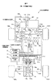
図1は、本発明の第1の実施の形態に係る四輪駆動車の構成例を示す概略図である。図1に示すように、この四輪駆動車100は、駆動源としてのエンジン101と、エンジン101の出力を変速する変速装置としてのトランスミッション103と、エンジン101の出力軸101aとトランスミッション103の入力軸103aとを締結するクラッチ102と、トランスミッション103の出力を二輪駆動状態と四輪駆動状態とに切替可能に左右の前輪104(左前輪104L及び右前輪104R)及び左右の後輪105(左後輪105L及び右後輪105R)に伝達する駆動力伝達系110と、駆動力配分制御装置1とを搭載している。駆動力配分制御装置1は、伝達トルクを調節可能な駆動力伝達装置2と、駆動力伝達装置2を制御する制御装置3とを備えて構成されている。この駆動力伝達装置2は、四輪駆動車100の走行状態を二輪駆動状態と四輪駆動状態とに切替可能としている。
[First Embodiment]
FIG. 1 is a schematic diagram showing a configuration example of a four-wheel drive vehicle according to a first embodiment of the present invention. As shown in FIG. 1, the four-
また、四輪駆動車100の車室内には、運転者が操作を行うためのステアリングホイール120、アクセルペダル121、ブレーキペダル122、クラッチペダル123、及びシフトレバー124が配置されている。
In addition, a
エンジン101は、アクセルペダル121の踏み込み量に応じた燃料が供給される内燃機関であり、四輪駆動車100が走行するための駆動力を、クランクシャフトに連結された出力軸101aから出力する。
The
クラッチ102は、例えば一対の回転部材の摩擦圧接によってトルクを伝達する乾式クラッチである。クラッチ102は、エンジンの出力軸101aに連結された第1ディスク102aと、トランスミッション103の入力軸103aに連結された第2ディスク102bとを有している。クラッチ102は、運転者によるクラッチペダル123の踏み込み量に応じた圧力を発生する図略の押圧機構により第1ディスク102aと第2ディスク102bとが圧接されることにより、第1及び第2ディスク102a,102bが摩擦係合し、エンジン101の出力軸101aとトランスミッション103の入力軸103aとを締結する。
The
運転者がクラッチペダル123を踏み込むと、第1ディスク102aと第2ディスク102bとが離間して、クラッチ102によるトルク伝達が遮断される。また、クラッチペダル123の踏み込み量が小さくなるにつれて第1ディスク102aと第2ディスク102bとを圧接させる押圧力が増大して第1及び第2ディスク102a,102bが摩擦摺動し、クラッチ102の締結力が増加する。これに伴い、エンジン101からトランスミッション103に伝達されるトルクが増大する。
When the driver depresses the
トランスミッション103は、シフトレバー124による運転者のギヤシフト操作によって、複数の段階にギヤ比を変化させることが可能な手動変速機である。トランスミッション103は、例えば第1速から第5速までの5段階(前進時)にギヤ比を変化させることが可能な5速ミッションである。また、トランスミッション103は、エンジン101の駆動力を駆動力伝達系110に伝達しない中立(ニュートラル)状態を形成することも可能である。
The
(駆動力伝達系の構成)
駆動力伝達系110は、左前輪104L及び右前輪104Rにトルクを配分するフロントデファレンシャル装置112と、トランスミッション103の出力軸のトルクをフロントデファレンシャル装置112のデフケース112aに伝達するギヤ機構111と、デフケース112aに連結された入力ギヤ113a、及び入力ギヤ113aと回転軸を直交させて噛み合う出力ギヤ113bを有するトランスファ113と、出力ギヤ113bに連結されたプロペラシャフト114と、駆動力伝達装置2と、駆動力伝達装置2を介してプロペラシャフト114のトルクが伝達されるピニオンギヤシャフト115と、ピニオンギヤシャフト115に伝達されたトルクを左後輪105L及び右後輪105Rに配分するリヤデファレンシャル装置116とを備えている。
(Configuration of driving force transmission system)
The driving force transmission system 110 includes a front
また、駆動力伝達系110は、フロントデファレンシャル装置112の一対のサイドギヤにそれぞれ連結されたドライブシャフト112L,112R、及びリヤデファレンシャル装置116の一対のサイドギヤにそれぞれ連結されたドライブシャフト116L,116Rを有している。ドライブシャフト112L,112Rは左前輪104L及び右前輪104Rにトルクを伝達し、ドライブシャフト116L,116Rは左後輪105L及び右後輪105Rトルクを伝達する。
Further, the driving force transmission system 110 has drive shafts 112L and 112R respectively connected to a pair of side gears of the front
リヤデファレンシャル装置116のデフケース116aの外周部には、リングギヤ116bが相対回転不能に設けられている。リングギヤ116bは、ピニオンギヤシャフト115のギヤ部115aと噛み合わされ、ピニオンギヤシャフト115からのトルクをデフケース116aに伝達する。
A
上記した駆動力伝達系110の各構成要素のうち、トランスファ113、プロペラシャフト114、ピニオンギヤシャフト115、リヤデファレンシャル装置116、及びドライブシャフト116L,116Rは、後輪105にエンジン101の駆動力を伝達する駆動力伝達部材の一例である。
Among the components of the driving force transmission system 110 described above, the
駆動力伝達系110は、上記構成により、左前輪104L及び右前輪104Rには常にトランスミッション103から出力されたトルクが伝達される。また、左後輪105L及び右後輪105Rには、駆動力伝達装置2の作動により、四輪駆動車100の走行状態に応じて必要時にトルクを伝達される。つまり、本実施の形態の四輪駆動車100では、左前輪104L及び右前輪104Rが主駆動輪、左後輪105L及び右後輪105Rが補助駆動輪である。
With the above configuration, the driving force transmission system 110 always transmits the torque output from the
(制御装置の構成)
駆動力配分制御装置1を構成する制御装置3は、ROMやRAM等からなる記憶部31と、CPU等の演算処理装置からなる制御部32と、制御部32によって制御される電流出力回路33とを備えている。制御装置3は、制御部32が記憶部31に記憶されたプログラムに基づいて動作することにより、四輪駆動車100の前輪104と後輪105との回転差及び運転者の加速操作量等に基づいて、後輪105側へ伝達すべき指令トルクの値を演算により求める。
(Configuration of control device)
The
電流出力回路33は、制御部32の演算処理によって求めた指令トルクに応じた電流を駆動力伝達装置2に供給する。電流出力回路33は、例えば図略のバッテリーから供給される電流をPWM(Pulse Width Modulation)制御により電流量を調節して出力するインバータ回路である。
The
制御装置3には、ステアリングホイール120に連結されたステアリングシャフト120aの回転を検出するための操舵角センサ300、エンジン101の出力軸101aの回転速度(時間当たりの回転数)を検出するエンジン回転速センサ301、アクセルペダル121の踏み込み量に応じたアクセル開度(加速操作量)を検出するアクセル開度センサ302、クラッチペダル123の踏み込み量(クラッチ操作量)に応じたクラッチペダルの位置を検出するクラッチペダル位置センサ303、及びシフトレバー124の位置を検出するシフトポジションセンサ304の各センサの検出信号が入力される。
The
また、制御装置3には、左前輪104L,右前輪104R,左後輪105L,右後輪105Rの各車輪に対応して設けられ、これら各車輪の回転速度を検出する車輪速センサ305〜308の検出信号が入力される。
Further, the
また、制御装置3には、外気温を検出する外気温センサ309の検出信号が入力される。外気温センサ309は、例えば四輪駆動車100のフロントバンパー(図示せず)の内側に配置されている。またさらに、制御装置3には、四輪駆動車100の前後方向の加速度を検出する前後加速度センサ310、横方向(車幅方向)の加速度を検出する横加速度センサ311、及びヨーレイトを検出するヨーレイトセンサ312の検出信号が入力される。
Further, the
これら各センサ300〜312の検出信号は、センサ本体に接続された信号線を介して直接制御装置3に入力してもよく、CAN(Controller Area Network)等の車載ネットワークを通じた通信によって制御装置3に入力してもよい。
The detection signals of these
(駆動力伝達装置2の構成)
駆動力伝達装置2は、プロペラシャフト114に連結された有底円筒状のアウタハウジング21と、ピニオンギヤシャフト115に連結された円筒状のインナシャフト22と、アウタハウジング21の内周面とインナシャフト22の外周面との間に配置された複数の摩擦板からなるメインクラッチ23とを有している。メインクラッチ23は、アウタハウジング21に相対回転不能にスプライン嵌合された複数のアウタクラッチプレート23aと、インナシャフト22に相対回転不能にスプライン嵌合された複数のインナクラッチプレート23bとを交互に配列して構成されている。アウタハウジング21とインナシャフト22との間には、潤滑油が封入されている。
(Configuration of the driving force transmission device 2)
The driving
また、アウタハウジング21とインナシャフト22との間には、メインクラッチ23を軸方向に押圧する押圧力を発生するための環状の電磁コイル24,電磁コイル24の電磁力により押圧されるパイロットクラッチ25,及びパイロットクラッチ25を介して伝達される回転力をメインクラッチ23を押圧する軸方向のスラスト力に変換するカム機構26が配置されている。
Further, between the outer housing 21 and the inner shaft 22, an annular electromagnetic coil 24 for generating a pressing force for pressing the main clutch 23 in the axial direction, and a
電磁コイル24には、制御装置3の電流出力回路33から励磁電流が供給される。電磁コイル24に励磁電流が供給されると、その電磁力によりパイロットクラッチ25を介してアウタハウジング21の回転力がカム機構26に伝達され、カム機構26が作動することにより、メインクラッチ23を押圧するスラスト力が発生する。これにより、アウタハウジング21からインナシャフト22に伝達される駆動力は、電磁コイル24に供給される励磁電流に応じて変化する。
Excitation current is supplied to the electromagnetic coil 24 from the
(制御装置の動作)
制御装置3は、電磁コイル25に供給する励磁電流を調節することにより、駆動力伝達装置2によるトルクの伝達量を制御する。制御装置3は、前後輪の回転速度の差や、エンジン101の出力トルク、選択されたトランスミッション103のギヤ段、駆動力伝達系110における最終減速比、及びステアリングホイール120の操作による操舵角等に基づいて後輪105に伝達すべきトルク値を算出し、算出されたトルク値に応じた励磁電流を駆動力伝達装置2の電磁コイル25に供給する通常制御機能を有している。
(Operation of control device)
The
また、制御装置3は、四輪駆動車100が停止状態又は前記四輪駆動車の車速が所定値よりも低い状態であり、かつエンジン101の出力軸101aの回転速度が所定値以上であり、かつクラッチ102の締結力の増加速度が所定値以上であるとき、所定時間にわたって左右後輪105L,105Rに伝達すべきトルク値を低減するように補正する補正機能とを有している。なお、四輪駆動車100の車速が所定値よりも低い状態とは、四輪駆動車100の前進時も後進時も含むが、いずれか一方でもよい。この所定値は、例えば四輪駆動車100の徐行時の速度である。
Further, the
(通常制御機能)
制御装置3の制御部32は、前輪104と後輪105の回転速度差に基づく第1トルクt1と、エンジン101の出力トルクや選択されたトランスミッション103のギヤ段等に基づく第2トルクt2と、操舵角に基づく第3トルクt3と、の和により指令トルクtcを演算する。
(Normal control function)
The
第1トルクt1の演算では、左右前輪104L,104Rに対応して設けられた車輪速センサ305,306の検出信号に基づいて前輪104の回転速度Vf(左右前輪104L,104Rの平均回転速度)を算出し、左右後輪105L,105Rに対応して設けられた車輪速センサ307,308の検出信号に基づいて後輪105の回転速度Vr(左右後輪105L,105Rの平均回転速度)を算出する。そして、前輪104の回転速度Vfから後輪105の回転速度Vrを減算して前後輪の回転速差ΔV(ΔV=Vf−Vr)を得る。
In the calculation of the first torque t1, the rotational speed Vf of the front wheels 104 (the average rotational speed of the left and right
そして、記憶部31に記憶された回転速差ΔVと第1トルクt1との関係を示す第1トルクマップを参照して第1トルクt1を求める。この第1トルクマップは、回転速差ΔVが大きいほど第1トルクt1が大きくなるように設定されている。これにより、例えば左前輪104L又は右前輪104Rにスリップが発生した場合に、エンジン101の駆動力を後輪105側により多くの割合で配分し、スリップを抑制することが可能となる。なお、第1トルクt1はさらに車速Sによって変更してもよい。
And the 1st torque t1 is calculated | required with reference to the 1st torque map which shows the relationship between rotational speed difference (DELTA) V memorize | stored in the memory |
第2トルクt2の演算では、左右前輪104L,104R及び左右後輪105L,105Rに伝達されるトルクの総和(駆動トルク)と第2トルクt2との関係を示す第2トルクマップを参照して第2トルクt2を求める。駆動トルクは、例えばエンジン101の出力トルク,選択されたトランスミッション103のギヤ段,及び駆動力伝達系110における最終減速比に基づいて演算により求めることができる。
The second torque t2 is calculated by referring to a second torque map showing the relationship between the total torque (drive torque) transmitted to the left and right
第2トルクマップは、駆動トルクが所定値未満の場合には、駆動トルクの増大に応じて第2トルクt2が増加又は一定の値となり、駆動トルクが上記所定値以上の場合には、駆動トルクが上記所定値未満の場合よりも大きな増加割合で、駆動トルクの増大に応じて第2トルクt2が増加するように設定されている。この所定値は、左右前輪104L,104Rのグリップ限界トルクに対応して設定された値である。
The second torque map indicates that when the driving torque is less than a predetermined value, the second torque t2 increases or becomes a constant value as the driving torque increases, and when the driving torque is equal to or greater than the predetermined value, the driving torque Is set so that the second torque t2 increases in accordance with the increase in the drive torque at a larger increase rate than in the case where is less than the predetermined value. This predetermined value is a value set corresponding to the grip limit torque of the left and right
これにより、例えば急加速時におけるエンジン101の大きな駆動力を前輪104側及び後輪105側に均等に配分し、主駆動輪である左右前輪104L,104Rに駆動力が集中した場合に生じ得る左前輪104L又は右前輪104Rのスリップを回避することが可能となる。なお、第2トルクt2はさらに車速Sによって変更してもよい。
Thus, for example, a large driving force of the
第3トルクt3の演算では、操舵角センサ300の検出信号からステアリングシャフト120aの操舵角を検出し、記憶部31に記憶された操舵角と第3トルクt3との関係を示す第3トルクマップを参照して第3トルクt3を求める。この第3トルクマップは、操舵角が大きいほど第3トルクt3が大きくなるように設定されている。
In the calculation of the third torque t3, the steering angle of the
これにより、操舵角が大きい旋回時の四輪駆動車100の車両挙動を安定させるとともに、操舵角が小さい旋回時や直進時の補助駆動輪である後輪への指令トルクtcを小さくすることで燃費が増大することを抑制できる。なお、第3トルクt3はさらに車速Sによって変更してもよい。
As a result, the vehicle behavior of the four-
制御装置3の制御部32は、第1トルクt1と第2トルクt2と第3トルク3tとの和を演算し、指令トルクtc(tc=t1+t2+t3)を求める。なお、第1トルクt1、第2トルクt2、及び第3トルク3tのうち、いずれか一つあるいは複数の組み合わせを指令トルクtcとしてもよい。
The
(補正機能)
制御装置3はまた、上記のように求めた指令トルクtcを、クラッチペダル位置センサ303により検出したクラッチペダル123の操作量に基づいて補正する補正機能を有している。本実施の形態の補正機能では、車輪速センサ305〜308の検出信号によって算出した車速Sが所定値(以下、この所定値を「閾値SHS」という)よりも低く、エンジン回転速センサ301の検出信号に基づいて算出したエンジン101の出力軸101aの回転速度Rが所定値(以下、この所定値を「閾値SHR」という)以上であり、かつクラッチペダル位置センサ303の検出信号に基づいて算出したクラッチ102の締結力の増加速度が所定値以上である場合に、通常制御機能によって前後輪の回転速差ΔV及びアクセル開度φに基づいて算出した指令トルクtcを低減する。
(Correction function)
The
閾値SHSは、例えば時速1〜5kmに設定することができる。なお、四輪駆動車100の車速Sは、車輪速センサ305,306の検出信号によって算出した前輪104の回転速度Vf、又は車輪速センサ307,308の検出信号によって算出した後輪105の回転速度Vrに基づいて求めることができる他、前後加速度センサ310の検出信号によって推定してもよい。
The threshold value SH S can be set to 1 to 5 km / h, for example. The vehicle speed S of the four-
閾値SHRは、四輪駆動状態でエンジン101の出力軸101aがその回転速度で回転しているときにクラッチ102が急激に繋がれた場合に、後輪105にエンジン101の駆動力を伝達する駆動力伝達部材に過大なトルクが伝達され、この駆動力伝達部材の確実な保護が行えなくなる回転速度よりも小さな値に設定される。この閾値SHRは、例えば2000r/min以上に設定することができる。
Threshold SH R transmits when the clutch 102 is coupled rapidly when the
また、本実施の形態では、クラッチペダル位置センサ303の検出信号に基づいて算出したクラッチペダル123の位置が第1位置から第2位置に至るまでの時間が所定値(以下、この所定値を「移動時間T1」という)以下のとき、クラッチ102の締結力の増加速度が所定値以上であると判定する。ここで、第2位置は第1位置よりもクラッチ102の締結力が大きくなる位置である。つまり、第1位置は第2位置よりもクラッチペダル123が大きく踏み込まれた位置である。また、移動時間T1は、運転者が急発進を行うことを意図してクラッチペダル123を操作した場合に、クラッチペダル123の位置が第1位置から第2位置に至るまでの時間に相当する時間であり、例えば0.2秒以下に設定することができる。
Further, in the present embodiment, the time until the position of the
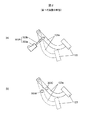
図2は、クラッチペダル123の位置を検出するためのクラッチペダル位置センサ303の構成例を示し、(a)はリニアスケール303Aを用いた場合の構成例、(b)は第1の近接スイッチ303B,第2の近接スイッチ303Cを用いた場合の構成例を説明する説明図である。図2では、クラッチペダル123が第1位置にあるときのクラッチペダル123、及びクラッチペダル123に連結されたクラッチレバー123aを破線で、クラッチペダル123が第2位置にあるときのクラッチペダル123、及びクラッチレバー123aを実線で示している。
FIG. 2 shows a configuration example of the clutch
図2(a)に示す例では、リニアスケール303Aが、本体部303aと、本体部303aに対して軸方向に移動可能な可動軸303bとを有し、可動軸303bの一端がクラッチレバー123aに揺動可能に連結されている。本体部303aは、図略の車体に支持されている。
In the example shown in FIG. 2A, the
運転者の踏み込み操作によりクラッチペダル123が移動すると、可動軸303bが本体部303aに対して軸方向に移動し、本体部303aは可動軸303bの移動量に応じた検出信号を出力する。制御装置3は、この検出信号に基づいて、クラッチペダル123の位置を連続的に検出可能である。
When the
図2(b)に示す例では、クラッチペダル123が第1位置にあるときにクラッチレバー123aに対向する位置に第1の近接スイッチ303Bが配置され、クラッチペダル123が第2位置にあるときにクラッチレバー123aに対向する位置に第2の近接スイッチ303Cが配置されている。
In the example shown in FIG. 2B, when the
第1の近接スイッチ303Bはクラッチペダル123が第1位置にあるときにオン信号を出力し、第2の近接スイッチ303Cはクラッチペダル123が第2位置にあるときにオン信号を出力する。これにより、制御装置3は、クラッチペダル123が第1位置及び第2位置にあることを検知可能である。
The
制御装置3は、車速Sが閾値SHSよりも低く、エンジン101の出力軸101aの回転速度Rが閾値SHR以上であり、かつクラッチペダル123の位置が第1位置から第2位置に至るまでの時間が所定値以下であると判定したとき、その後所定時間(以下、この所定時間を「指令トルク低減時間T2」という)にわたって指令トルクtcを低減するように補正し、補正後の指令トルクtcに応じた電流を励磁電流として駆動力伝達装置2の電磁コイル25に供給する。
この補正は、指令トルクtcに1未満の係数k1を乗じた積を補正後の指令トルクtcとしてもよく(補正後の指令トルクtc=補正前の指令トルクtc×係数k1(0<k1<1))、予め定められた所定のトルク値に指令トルクtcを置き換えるものでもよい。指令トルクtcに係数k1を乗じて補正後の指令トルクtcとする場合、係数k1は例えば0.8以下、より望ましくは0.5以下であるとよい。また、予め定められたトルク値に指令トルクtcを置き換える場合、この予め定められたトルク値は、例えば駆動力伝達装置2による最大のトルク伝達容量の80%以下、より望ましくは50%以下であるとよい。
This correction may be obtained by multiplying the command torque tc by a
また、指令トルク低減時間T2は、出力軸101aの回転速度Rが閾値SHRよりも高い状態からクラッチ102が急激に繋げられた場合に、前輪104にエンジン101のトルクが伝達されて出力軸101aの回転速度Rが低下するのに要する時間以上の時間に設定される。この指令トルク低減時間T2は、例えば0.2〜5秒に設定することができる。
Also, the command torque reduction time T 2 are, the output shaft from the rotation speed R is higher than the threshold value SH R state of 101a when the clutch 102 is linked abruptly, the output shaft is transmitted torque of the
そして、制御装置3は、制御部32が電流出力回路33を制御して、補正後の指令トルクtcに応じた電流を励磁電流として駆動力伝達装置2の電磁コイル25に供給する。
Then, in the
(制御装置の処理手順)
図3は、制御装置3の制御部32が実行する処理の一例を示すフローチャートである。制御部32は、このフローチャートに示す処理を所定の制御周期(例えば100ms)ごとに繰り返し実行する。また、このフローチャートでは、図2(a)に例示するリニアスケール303Aによってクラッチペダル123の位置を検出する場合について説明する。
(Processing procedure of control device)
FIG. 3 is a flowchart illustrating an example of processing executed by the
まず、制御部32は、前述の通常制御機能により、第1トルクマップを参照して回転速差ΔVに応じた第1トルクt1を演算し、第2トルクマップを参照して駆動トルクに応じた第2トルクt2を演算し、第3トルクマップを参照して操舵角に応じた第3トルクt3を演算する。またさらに、制御部32は、第1トルクt1に第2トルクt2と第3トルクt3とを加算して指令トルクtcを求める(ステップS100)。
First, the
次に、制御部32は、低減フラグがオンしているか否かを判定する(ステップS101)。この低減フラグは、低車速・エンジン高回転で、かつクラッチペダル123が踏み込まれた状態を検知したことを示すフラグである。低減フラグがオンでない場合(S101:No)、制御部32は、車速Sが閾値SHSよりも低いか否かを判定する(ステップS102)。車速Sが閾値SHSよりも低い場合(S102:Yes)、制御部32は、エンジン101の出力軸101aの回転速度R(エンジン回転数)が閾値SHR以上か否かを判定する(ステップS103)。
Next, the
エンジン回転数が閾値SHR以上である場合(S103:Yes)、制御部32は、クラッチペダル位置センサ303(303A)の検出信号に基づいて算出したクラッチペダル123の位置が第1の閾値SHC1以上であるか否かを判定する(ステップS104)。ここで、第1の閾値SHC1は、クラッチペダル123の位置の第1位置に対応する値である。また、クラッチペダル123の位置は、運転者によるクラッチペダル123の踏み込み量を示し、踏み込まれた状態(クラッチ102が開放に近い状態)で大きく、踏み込み量が小さくなるにつれて小さくなる値をとるものとする。
If the engine speed is the threshold value SH R above (S103: Yes), the
クラッチペダル123の位置が第1の閾値SHC1以上である場合(S104:Yes)、制御部32は、低減フラグをオンにし(ステップS105)、ステップS100で算出した指令トルクtcを低減する補正を行う(ステップS106)。
When the position of the
一方、車速Sが閾値SHSよりも低くない場合(S102:No)、エンジン回転数が閾値SHR以上でない場合(S103:No)、又はクラッチペダル123の位置が第1の閾値SHC1以上でない場合(S104:No)、制御部32は、ステップS100で算出した指令トルクtcを低減する補正を行うことなく処理を終了する。
On the other hand, when the vehicle speed S is not lower than the threshold value SH S (S102: No), when the engine speed is not the threshold value SH R above (S103: No), or the position of the
また、制御部32は、ステップS101の判定で低減フラグがオンである場合(S101:Yes)、継続フラグがオンしているか否かを判定する(ステップS107)。この継続フラグは、急発進後における指令トルクtcを補正する処理の継続時間中であるか否かを示すフラグである。
Moreover, the
継続フラグがオンしていない場合(S107:No)、制御部32は、クラッチペダル位置センサ303(303A)の検出信号に基づいて算出したクラッチペダル123の位置が第1の閾値SHC1以上であるか否かを判定する(ステップS108)。
When the continuation flag is not turned on (S107: No), the
制御部32は、クラッチペダル123の位置が第1の閾値SHC1以上であれば(S108:Yes)、ステップS100で算出した指令トルクtcを低減する補正を行う(ステップS106)。また、クラッチペダル123の位置が第1の閾値SHC1以上でなければ(S108:No)、低減カウンタが閾値SHT1未満であるか否かを判定する(ステップS109)。ここで、閾値SHT1は、上記の移動時間T1に対応して定められた値であり、例えば制御周期が100msである場合は、閾値SHT1=移動時間T1(秒)×10となる。
低減カウンタが閾値SHT1未満である場合(S109:Yes)、制御部32は低減カウンタをインクリメントし(ステップS110)、クラッチペダル123の位置が第2の閾値SHC2未満であるか否かを判定する(ステップS111)。ここで、第2の閾値SHC2は、クラッチペダル123の位置の第2位置に対応する値である。クラッチペダル123の位置が第2の閾値SHC2未満である場合(S111:Yes)、制御部32は、継続フラグをオンにすると共に低減カウンタをクリアし(ステップS112)、ステップS100で算出した指令トルクtcを低減する補正を行う(ステップS106)。
When the reduction counter is less than the threshold value SH T1 (S109: Yes), the
また、クラッチペダル123の位置が第2の閾値SHC2未満でない場合(S111:No)、制御部32は、継続フラグをオンにすることなく、ステップS100で算出した指令トルクtcを低減する補正を行う(ステップS106)。
Further, when the position of the
一方、ステップS109の判定で低減カウンタが閾値SHT1未満でない場合(S109:No)、制御部32は、低減カウンタをクリアすると共に低減フラグをクリアし(ステップS113)、ステップS100で算出した指令トルクtcを低減する補正を行うことなく処理を終了する。
On the other hand, when the reduction counter is not less than the threshold value SH T1 in the determination in step S109 (S109: No), the
また、ステップS107の判定で継続フラグがオンである場合(S107:Yes)、制御部32は、継続カウンタが閾値SHT2未満であるか否かを判定する(ステップS114)。ここで、閾値SHT2は、上記の指令トルク低減時間T2に対応して定められた値であり、例えば制御周期が100msである場合は、閾値SHT2=指令トルク低減時間T2(秒)×10となる。
Also, if the continuation flag is determined in step S107 it is ON (S107: Yes), the
継続カウンタが閾値SHT2未満である場合(S114:Yes)、制御部32は、継続カウンタをインクリメントし(ステップS115)、ステップS100で算出した指令トルクtcを低減する補正を行う(ステップS106)。このように、クラッチ位置が第2の閾値SHC2未満となった後、継続カウンタが閾値SHT2以上となるまで、指令トルクtcを低減する補正が継続して行われる。
When the continuation counter is less than the threshold value SH T2 (S114: Yes), the
一方、継続カウンタが閾値SHT2未満でない場合(S114:No)、制御部32は、継続フラグ及び低減フラグをクリアすると共に、継続カウンタをクリアし(ステップS116)、ステップS100で算出した指令トルクtcを低減する補正を行うことなく処理を終了する。
On the other hand, when the continuation counter is not less than the threshold value SH T2 (S114: No), the
なお、図2(b)に例示する第1近接スイッチ303B及び第2近接スイッチ303Cによってクラッチペダル123の位置を検出する場合は、第1近接スイッチ303Bの検出信号がオンしたときにステップS105の処理(低減フラグオン)を行い、第2近接スイッチ303Cの検出信号がオンしたときにステップS112の処理(継続フラグオン)を行うようにすればよい。
When the position of the
(第1の実施の形態の作用及び効果)
以上説明した第1の実施の形態によれば、クラッチペダル123の位置が第1位置から第2位置まで移動し、その移動に要した時間が移動時間T1以下であることを検知したとき、その後指令トルク低減時間T2にわたって、指令トルクtcが低減される。つまり、クラッチペダル123を急激に締結させる操作がされた場合には、当該操作がされなかった場合に比較して、後輪105側に伝達されるトルクが所定時間にわたって低減される。これにより、エンジン101の回転数が大きい状態からの急発進時にも、後輪105にエンジン101の駆動力を伝達する駆動力伝達部材に過大な負担がかかることを抑制することができる。また、クラッチ102の締結力の増加速度、すなわちクラッチペダル123の位置の時間当たりの変化量(移動速度)を考慮しない場合に比較して、四輪駆動車100の急発進状態をより適切に検知することが可能となる。
(Operation and effect of the first embodiment)
According to the first embodiment described above, when the position of the
[第2の実施の形態]
次に、本発明の第2の実施の形態について図4を参照して説明する。本実施の形態は、図3に示すフローチャートのステップS106の指令トルクtcを補正する処理の後に、さらに指令トルクtcを低減する再補正処理を行う他は、第1の実施の形態と共通である。図4では、この再補正処理における処理内容の一例を示している。
[Second Embodiment]
Next, a second embodiment of the present invention will be described with reference to FIG. This embodiment, after the processing for correcting the command torque tc the flow chart of the steps S 106 shown in FIG. 3, addition of re correction processing for reducing further command torque tc is the same as the first embodiment is there. FIG. 4 shows an example of processing contents in this recorrection processing.
再補正処理では、制御部32が、外気温センサ309により検出した外気温の低下に応じて、指令トルクtcを低減する場合の低減量を大きくし、また四輪駆動車100の走行路における進行方向が上り勾配の場合に、指令トルクtcを低減する場合の低減量を大きくする。
In the re-correction process, the
より具体的には、制御部32は、外気温センサ309の検出信号に基づいて外気温Teを算出する(ステップ200)。次に、制御部32は、ステップS200で算出した外気温Teが閾値SHtempよりも低いか否かを判定する(ステップS201)。閾値SHtempは、駆動力伝達装置2のハウジング21とインナシャフト22との間の空間に充填された潤滑油の粘性の増大により、電磁コイル25に供給した励磁電流に対応したトルク以上のトルクが後輪105側に伝達される温度であり、例えば0℃に設定される。
More specifically, the
この判定の結果、外気温Teが閾値SHtempよりも低い場合には、ステップS106で補正された補正後の指令トルクtcをさらに低減する補正を行う(ステップS202)。
The result of this determination, when the outside air temperature Te is lower than the threshold value SH temp further performs correction to reduce the command torque tc corrected by the correction in step S 106 (step S202).
このステップS202の処理では、例えばステップS106における補正後の指令トルクtcに、1未満の係数k2を乗じた積を再補正後の指令トルクtcとし、又は予め定められた所定のトルク値に指令トルクtcを置き換える。この場合、係数k2は例えば0.5〜0.8であるとよい。また、この予め定められたトルク値は、例えば駆動力伝達装置2による最大のトルク伝達容量の50%以下、より望ましくは30%以下であるとよい。
In the process of step S202, for example, the command torque tc corrected in step S 106, the command torque tc after re correct, multiplied by 1 less than the coefficient k 2, or in advance to a predetermined torque value determined Replace command torque tc. In this case, the coefficient k 2 may If it is for example 0.5 to 0.8. The predetermined torque value may be, for example, 50% or less of the maximum torque transmission capacity by the driving
次に、制御部32は、前後加速度センサ310の検出信号に基づいて、四輪駆動車100の前後方向の傾斜角θを算出する(ステップS203)。ここで、傾斜角θは、四輪駆動車100の前輪104の位置が後輪105の位置よりも鉛直方向に高い場合に正の値をとるものとする。なお、このステップS203の処理が実行されるのは、ステップS102(図3参照)の処理で、車速Sが閾値SHSよりも低いと判定された場合であるので、ステップS203における前後加速度センサ310の検出信号は、四輪駆動車100の前後方向の傾斜角θに対応した値となっている。
Next, the
次に、制御部32は、ステップS203で算出した傾斜角θが閾値SHgraよりも大きいか否かを判定する(ステップS204)。閾値SHgraは、例えば5°以上の値に設定される。この判定の結果、傾斜角θが閾値SHgraよりも大きい場合(S204:Yes)には、ステップS106又はステップS202で補正された再補正後の指令トルクtcをさらに低減する補正を行う(ステップS205)。
Next, the
このステップS205の処理では、例えばステップS106又はステップS202における補正後の指令トルクtcに、1未満の係数k3を乗じた積を再補正後の指令トルクtcとし、又は予め定められた所定のトルク値に指令トルクtcを置き換える。この場合、係数k3は例えば0.5〜0.8であるとよい。また、この予め定められたトルク値は、例えば駆動力伝達装置2による最大のトルク伝達容量の50%以下、より望ましくは30%以下であるとよい。
In the process of step S205, for example, the command torque tc corrected in step S 106 or step S202, the command torque tc after re correct, multiplied by one less than the coefficient k 3, or a predetermined a predetermined The command torque tc is replaced with the torque value. In this case, the coefficient k 3 is may is for example 0.5 to 0.8. The predetermined torque value may be, for example, 50% or less of the maximum torque transmission capacity by the driving
(第2の実施の形態の作用及び効果)
外気温Teが閾値SHtempよりも低い場合に指令トルクtcをさらに低減する補正を行うので、駆動力伝達装置2のハウジング21とインナシャフト22との間の空間に充填された潤滑油の粘性の増大によって後輪105側に過大なトルクが伝達されることを抑制することができる。
(Operation and effect of the second embodiment)
When the outside air temperature Te is lower than the threshold value SH temp, correction is performed to further reduce the command torque tc, so that the viscosity of the lubricating oil filled in the space between the housing 21 and the inner shaft 22 of the driving
また、四輪駆動車100の前後方向の傾斜角θが閾値SHgraよりも大きい場合に指令トルクtcをさらに低減する補正を行うので、後輪105側に荷重がかかり、前輪104にスリップが発生しやすく、後輪105側に大きなトルクが伝達されやすい状況にある場合に、エンジン101の駆動力を後輪105に伝達する駆動力伝達部材に過大なトルクが伝達されることを抑制することができる。特に、所謂坂道発進を行う場合には、エンジン101の回転数を予め上げた状態からクラッチ102を締結させる操作がなされることが多いが、このような場合にも、後輪105側の駆動力伝達部材を適切に保護することが可能となる。
Further, when the inclination angle θ in the front-rear direction of the four-
[他の実施の形態]
以上、本発明の駆動力配分制御装置、及び四輪駆動車を上記実施の形態に基づいて説明したが、本発明はこれらの実施の形態に限定されるものではなく、その要旨を逸脱しない範囲で種々の態様において実施することが可能である。
[Other embodiments]
As mentioned above, although the driving force distribution control apparatus and four-wheel drive vehicle of this invention were demonstrated based on the said embodiment, this invention is not limited to these embodiment, The range which does not deviate from the summary It can be implemented in various ways.
例えば、上記各実施の形態では、クラッチペダル123の位置が第1位置から第2位置に至るまでの時間が所定値以下のとき、クラッチ102の締結力の増加速度が所定値以上であると判定したが、これに限らず、例えばクラッチ102の第1ディスク102aと第2ディスク102bとを圧接させる押圧機構の押圧力を検出し、この押圧力の時間当たりの変化量に基づいて、クラッチ102の締結力の増加速度が所定値以上であるか否かを判定してもよい。
For example, in each of the above embodiments, when the time until the position of the
また、上記各実施の形態に加えて、車速やエンジン回転数に基づいて車重を推定、または、検知し、この推定、又は、検知された車重に応じて指令トルク値をさらに補正してもよい。例えば、求められた車重が大きいほど指令トルク値tcが小さくなるよう補正してもよい。上記第2の実施の形態で、ステップS205の処理により再補正された再補正後の指令トルク値tcに、車重が大きく(重く)なるにつれて値が小さくなる係数k4を乗じた積を再々補正後の指令トルク値tcとしてもよい。あるいは、この求められた車重が閾値より大きいか否かを判定する。この判定の結果、車重が閾値よりも大きい(重い)場合には、指令トルクtcをさらに低減する補正を行う。上記第2の実施の形態で、ステップS205の処理により再補正された再補正後の指令トルク値tcに、1未満の係数k5を乗じた積を再々補正後の指令トルク値tcとし、又は予め定められた所定のトルク値に指令トルクtcを置き換えてもよい。 In addition to the above embodiments, the vehicle weight is estimated or detected based on the vehicle speed and the engine speed, and the command torque value is further corrected according to the estimated or detected vehicle weight. Also good. For example, the command torque value tc may be corrected so as to decrease as the calculated vehicle weight increases. In the second embodiment, the product obtained by multiplying the re-corrected command torque value tc re-corrected by the process of step S205 by a coefficient k4 that decreases as the vehicle weight increases (heavy) is corrected again. The subsequent command torque value tc may be used. Alternatively, it is determined whether or not the calculated vehicle weight is greater than a threshold value. As a result of this determination, when the vehicle weight is larger (heavy) than the threshold, correction for further reducing the command torque tc is performed. In the second embodiment, a product obtained by multiplying the re-corrected command torque value tc re-corrected by the process of step S205 by a coefficient k5 less than 1 is used as the re-corrected command torque value tc, or in advance The command torque tc may be replaced with a predetermined predetermined torque value.
また、上記各実施の形態では、前輪104を主駆動輪とし、後輪105を補助駆動輪とした場合について説明したが、これに限らず、前輪104を補助駆動輪とし、後輪105を主駆動輪とする四輪駆動車にも本発明を適用することが可能である。 In each of the above embodiments, the case where the front wheel 104 is the main driving wheel and the rear wheel 105 is the auxiliary driving wheel has been described. However, the present invention is not limited thereto, and the front wheel 104 is the auxiliary driving wheel and the rear wheel 105 is the main driving wheel. The present invention can also be applied to a four-wheel drive vehicle as a drive wheel.
1…駆動力配分制御装置、2…駆動力伝達装置、3…制御装置、21…ハウジング、22…インナシャフト、22a,22b…スプライン歯、22c…段差部、23…メインクラッチ、24…パイロットクラッチ、25…電磁コイル、26…アーマチャ、26a…スプライン歯、27…カム機構、31…記憶部、32…制御部、33…電流出力回路、100…四輪駆動車、101…エンジン、101a…出力軸、102…クラッチ、102a…第1ディスク、102b…第2ディスク、103…トランスミッション、103a…入力軸、104…前輪、104L…左前輪、104R…右前輪、105…後輪、105L…左後輪、105R…右後輪、110…駆動力伝達系、111…ギヤ機構、112…フロントデファレンシャル装置、112L,112R…ドライブシャフト、112a…デフケース、113…ギヤ機構、114…プロペラシャフト、115…ピニオンギヤシャフト、115a…ギヤ部、116…リヤデファレンシャル装置、116L,116R…ドライブシャフト、116a…デフケース、116b…リングギヤ、120…ステアリングホイール120、120a…ステアリングシャフト、121…アクセルペダル、122…ブレーキペダル、123…クラッチペダル、123a…クラッチレバー、124…シフトレバー、211…フロントハウジング、211a…底部、211b…スプライン歯、212…リヤハウジング、212a…第1部材、212b…第2部材、212c…第3部材、231…アウタクラッチプレート、231a…突起、232…インナクラッチプレート、232a…突起、232b…油孔、241…アウタクラッチプレート、241a…突起、242…インナクラッチプレート、242b…突起、251…ヨーク、252…電線、271…パイロットカム、271a…スプライン歯、271b,273b…カム溝、272…カムボール、273…メインカム、273a…スプライン歯、274…リテーナ、281…玉軸受、282…針状ころ軸受、283…玉軸受、284…スラスト針状ころ軸受、300…操舵角センサ、301…エンジン回転速センサ、302…アクセル開度センサ、303…クラッチペダル位置センサ、303A…リニアスケール、303a…本体部、303b…可動軸、303B…第1近接スイッチ、303C…第2近接スイッチ、304…シフトポジションセンサ、305〜308…車輪速センサ、309…外気温センサ、310…前後加速度センサ、311…横加速度センサ、312…ヨーレイトセンサ、G…磁路、O…回転軸線
DESCRIPTION OF
Claims (7)
前記補助駆動輪に伝達すべきトルク値を求める制御装置と、
前記制御装置が求めたトルク値に応じたトルクを前記補助駆動輪に伝達する駆動力伝達装置とを備え、
前記制御装置は、前記四輪駆動車が停止状態又は前記四輪駆動車の車速が所定値よりも低い状態であり、かつ前記クラッチの締結力の増加速度が所定値以上であることを検知したとき、所定時間にわたって前記補助駆動輪に伝達すべきトルク値を低減するとともに、外気温の低下に応じて、前記補助駆動輪に伝達すべきトルク値を低減する場合の低減量を大きくする駆動力配分制御装置。 An engine for generating driving force, a transmission for shifting the rotation of the output shaft of the engine, a clutch for fastening the output shaft of the engine and the input shaft of the transmission, and the output of the transmission for front wheels or rear wheels It is mounted on a four-wheel drive vehicle having a driving force transmission system capable of transmitting to one main drive wheel and the other auxiliary drive wheel,
A control device for obtaining a torque value to be transmitted to the auxiliary drive wheel;
A driving force transmission device that transmits torque according to the torque value obtained by the control device to the auxiliary driving wheel;
The control device detects that the four-wheel drive vehicle is in a stopped state or the vehicle speed of the four-wheel drive vehicle is lower than a predetermined value, and that the increasing speed of the engagement force of the clutch is equal to or higher than a predetermined value. Driving force to reduce the torque value to be transmitted to the auxiliary driving wheel over a predetermined time and to increase the amount of reduction when reducing the torque value to be transmitted to the auxiliary driving wheel in accordance with a decrease in outside air temperature Distribution controller.
請求項1に記載の駆動力配分制御装置。 The control device is configured such that the four-wheel drive vehicle is in a stopped state or the vehicle speed of the four-wheel drive vehicle is lower than a predetermined value, the increasing speed of the engagement force of the clutch is equal to or higher than a predetermined value, and the engine When the rotational speed of the output shaft is greater than or equal to a predetermined value, the torque value to be transmitted to the auxiliary drive wheel over a predetermined time is reduced, and the torque value to be transmitted to the auxiliary drive wheel is reduced as the outside air temperature decreases. The driving force distribution control device according to claim 1, wherein a reduction amount in the case of performing is increased .
請求項1又は2に記載の駆動力配分制御装置。 The controller increases the clutch engagement force when the time from the first position to the second position where the clutch engagement force is greater than the first position is less than or equal to a predetermined value. The driving force distribution control device according to claim 1, wherein the speed is determined to be greater than or equal to a predetermined value.
請求項1乃至3の何れか1項に記載の駆動力配分制御装置。 The driving force distribution control device according to any one of claims 1 to 3 , wherein the control device increases a reduction amount of the torque value when the traveling direction of the four-wheel drive vehicle is an upward gradient .
前記補助駆動輪に伝達すべきトルク値を求める制御装置と、
前記制御装置が求めたトルク値に応じたトルクを前記補助駆動輪に伝達する駆動力伝達装置とを備え、
前記制御装置は、前記四輪駆動車が停止状態又は前記四輪駆動車の車速が所定値よりも低い状態であり、かつ前記クラッチの締結力の増加速度が所定値以上であることを検知したとき、所定時間にわたって前記補助駆動輪に伝達すべきトルク値を低減するとともに、前記四輪駆動車の進行方向が上り勾配の場合にトルク値の低減量を大きくする駆動力配分制御装置。 An engine for generating driving force, a transmission for shifting the rotation of the output shaft of the engine, a clutch for fastening the output shaft of the engine and the input shaft of the transmission, and the output of the transmission for front wheels or rear wheels It is mounted on a four-wheel drive vehicle having a driving force transmission system capable of transmitting to one main drive wheel and the other auxiliary drive wheel,
A control device for obtaining a torque value to be transmitted to the auxiliary drive wheel;
A driving force transmission device that transmits torque according to the torque value obtained by the control device to the auxiliary driving wheel;
The control device detects that the four-wheel drive vehicle is in a stopped state or the vehicle speed of the four-wheel drive vehicle is lower than a predetermined value, and that the increasing speed of the engagement force of the clutch is equal to or higher than a predetermined value. when, while reducing the torque value to be transmitted to the auxiliary drive wheels for a predetermined time, the traveling direction of the four-wheel drive vehicle is reduced weight greatly to that driving force distribution control device for a torque value when the upward gradient.
前記エンジンの出力軸の回転を変速する変速装置と、
前記エンジンの出力軸と前記変速装置の入力軸とを締結するクラッチと、
前記変速装置の出力を前輪又は後輪の一方の主駆動輪と他方の補助駆動輪とに伝達することが可能な駆動力伝達系と、
前記補助駆動輪に伝達すべきトルク値を求める制御装置と、
前記制御装置が求めたトルク値に応じたトルクを前記補助駆動輪に伝達する駆動力伝達装置とを備え、
前記制御装置は、前記車両が停止状態又は前記車両の車速が所定値よりも低い状態であり、かつ前記クラッチの締結力の増加速度が所定値以上であることを検知したとき、所定時間にわたって前記補助駆動輪に伝達すべきトルク値を低減するとともに、外気温の低下に応じて、前記補助駆動輪に伝達すべきトルク値を低減する場合の低減量を大きくする四輪駆動車。 An engine that generates the driving force of the vehicle;
A transmission for shifting the rotation of the output shaft of the engine;
A clutch for fastening the output shaft of the engine and the input shaft of the transmission;
A driving force transmission system capable of transmitting the output of the transmission to one main driving wheel and the other auxiliary driving wheel of the front wheel or the rear wheel;
A control device for obtaining a torque value to be transmitted to the auxiliary drive wheel;
A driving force transmission device that transmits torque according to the torque value obtained by the control device to the auxiliary driving wheel;
When the control device detects that the vehicle is in a stopped state or the vehicle speed of the vehicle is lower than a predetermined value and that the increasing speed of the engagement force of the clutch is equal to or higher than a predetermined value, the control device A four-wheel drive vehicle that reduces the torque value to be transmitted to the auxiliary drive wheels and increases the amount of reduction when the torque value to be transmitted to the auxiliary drive wheels is reduced as the outside air temperature decreases .
前記エンジンの出力軸の回転を変速する変速装置と、 A transmission for shifting the rotation of the output shaft of the engine;
前記エンジンの出力軸と前記変速装置の入力軸とを締結するクラッチと、 A clutch for fastening the output shaft of the engine and the input shaft of the transmission;
前記変速装置の出力を前輪又は後輪の一方の主駆動輪と他方の補助駆動輪とに伝達することが可能な駆動力伝達系と、 A driving force transmission system capable of transmitting the output of the transmission to one main driving wheel and the other auxiliary driving wheel of the front wheel or the rear wheel;
前記補助駆動輪に伝達すべきトルク値を求める制御装置と、 A control device for obtaining a torque value to be transmitted to the auxiliary drive wheel;
前記制御装置が求めたトルク値に応じたトルクを前記補助駆動輪に伝達する駆動力伝達装置とを備え、 A driving force transmission device that transmits torque according to the torque value obtained by the control device to the auxiliary driving wheel;
前記制御装置は、前記車両が停止状態又は前記車両の車速が所定値よりも低い状態であり、かつ前記クラッチの締結力の増加速度が所定値以上であることを検知したとき、所定時間にわたって前記補助駆動輪に伝達すべきトルク値を低減するとともに、前記車両の進行方向が上り勾配の場合にトルク値の低減量を大きくする四輪駆動車。 When the control device detects that the vehicle is in a stopped state or the vehicle speed of the vehicle is lower than a predetermined value and that the increasing speed of the engagement force of the clutch is equal to or higher than a predetermined value, the control device A four-wheel drive vehicle that reduces a torque value to be transmitted to auxiliary drive wheels and increases a torque value reduction amount when the traveling direction of the vehicle is uphill.
Priority Applications (4)
| Application Number | Priority Date | Filing Date | Title |
|---|---|---|---|
| JP2011168200A JP5808601B2 (en) | 2011-08-01 | 2011-08-01 | Driving force distribution control device and four-wheel drive vehicle |
| US13/564,329 US8538650B2 (en) | 2011-08-01 | 2012-08-01 | Driving force distribution control device and four-wheel-drive vehicle |
| CN201210272309.7A CN102910068B (en) | 2011-08-01 | 2012-08-01 | Driving force distribution controls device and four-wheel drive vehicle |
| EP12178803.8A EP2554423B1 (en) | 2011-08-01 | 2012-08-01 | Driving force distribution control device and four-wheel-drive vehicle |
Applications Claiming Priority (1)
| Application Number | Priority Date | Filing Date | Title |
|---|---|---|---|
| JP2011168200A JP5808601B2 (en) | 2011-08-01 | 2011-08-01 | Driving force distribution control device and four-wheel drive vehicle |
Publications (3)
| Publication Number | Publication Date |
|---|---|
| JP2013032058A JP2013032058A (en) | 2013-02-14 |
| JP2013032058A5 JP2013032058A5 (en) | 2014-07-24 |
| JP5808601B2 true JP5808601B2 (en) | 2015-11-10 |
Family
ID=47002538
Family Applications (1)
| Application Number | Title | Priority Date | Filing Date |
|---|---|---|---|
| JP2011168200A Active JP5808601B2 (en) | 2011-08-01 | 2011-08-01 | Driving force distribution control device and four-wheel drive vehicle |
Country Status (4)
| Country | Link |
|---|---|
| US (1) | US8538650B2 (en) |
| EP (1) | EP2554423B1 (en) |
| JP (1) | JP5808601B2 (en) |
| CN (1) | CN102910068B (en) |
Families Citing this family (10)
| Publication number | Priority date | Publication date | Assignee | Title |
|---|---|---|---|---|
| JP2014035063A (en) * | 2012-08-10 | 2014-02-24 | Yamaha Motor Co Ltd | Automatic transmission apparatus and straddle type vehicle equipped with the same |
| JP5841584B2 (en) * | 2013-12-06 | 2016-01-13 | 富士重工業株式会社 | Powertrain control device |
| JP6020514B2 (en) * | 2014-05-29 | 2016-11-02 | トヨタ自動車株式会社 | Control device for four-wheel drive vehicle |
| ITUB20155447A1 (en) * | 2015-11-11 | 2017-05-11 | Fpt Ind Spa | METHOD AND DEVICE FOR THE CONTROL OF AN INTERNAL COMBUSTION ENGINE OF AN AGRICULTURAL VEHICLE AND AGRICULTURAL VEHICLE INCLUDING THE DEVICE |
| US10158303B2 (en) * | 2016-09-15 | 2018-12-18 | The Boeing Company | Methods and apparatus to perform torque balance control of co-shafted motors |
| JP6786986B2 (en) * | 2016-09-16 | 2020-11-18 | 株式会社ジェイテクト | Control device for four-wheel drive vehicles |
| JP6946630B2 (en) * | 2016-10-04 | 2021-10-06 | 株式会社ジェイテクト | Control device for driving force transmission device and road surface condition judgment device |
| CN110023129B (en) * | 2016-12-13 | 2022-04-22 | 本田技研工业株式会社 | Control device for torque distribution device |
| JP6412192B2 (en) * | 2017-03-17 | 2018-10-24 | 株式会社Subaru | Vehicle control device |
| CN109774783B (en) * | 2017-11-10 | 2022-05-13 | 现代自动车株式会社 | Control method and control system for electric power steering |
Family Cites Families (5)
| Publication number | Priority date | Publication date | Assignee | Title |
|---|---|---|---|---|
| JP3791625B2 (en) * | 1995-08-11 | 2006-06-28 | 日産自動車株式会社 | Four-wheel drive control device for vehicle |
| JP4237378B2 (en) * | 2000-06-29 | 2009-03-11 | 富士重工業株式会社 | Vehicle driving force transmission control device |
| DE60324227D1 (en) * | 2002-06-19 | 2008-12-04 | Jtekt Corp | Control method for driving force distribution and device for a vehicle with four-wheel drive |
| JP3823072B2 (en) | 2002-06-19 | 2006-09-20 | 株式会社ジェイテクト | Front and rear wheel drive vehicles |
| JP2004306802A (en) * | 2003-04-08 | 2004-11-04 | Toyota Motor Corp | Control device of driving force distribution apparatus for vehicle |
-
2011
- 2011-08-01 JP JP2011168200A patent/JP5808601B2/en active Active
-
2012
- 2012-08-01 EP EP12178803.8A patent/EP2554423B1/en not_active Not-in-force
- 2012-08-01 CN CN201210272309.7A patent/CN102910068B/en active Active
- 2012-08-01 US US13/564,329 patent/US8538650B2/en active Active
Also Published As
| Publication number | Publication date |
|---|---|
| CN102910068A (en) | 2013-02-06 |
| US20130035833A1 (en) | 2013-02-07 |
| JP2013032058A (en) | 2013-02-14 |
| EP2554423A1 (en) | 2013-02-06 |
| CN102910068B (en) | 2016-12-21 |
| US8538650B2 (en) | 2013-09-17 |
| EP2554423B1 (en) | 2017-06-07 |
Similar Documents
| Publication | Publication Date | Title |
|---|---|---|
| JP5808601B2 (en) | Driving force distribution control device and four-wheel drive vehicle | |
| JP5559421B2 (en) | Driving force distribution control device and four-wheel drive vehicle | |
| JP5827059B2 (en) | Road friction coefficient estimation device, driving force distribution control device, and four-wheel drive vehicle | |
| JP5833857B2 (en) | Driving force distribution control device and four-wheel drive vehicle | |
| CN105644361B (en) | Control device for four-wheel drive vehicle | |
| JP4267495B2 (en) | Driving force control method for four-wheel drive vehicle | |
| US6704627B2 (en) | Drive force distribution apparatus for hybrid vehicle | |
| JP6051833B2 (en) | Four-wheel drive vehicle control system | |
| JP4554252B2 (en) | Control method for four-wheel drive vehicle | |
| JP4476742B2 (en) | Control method for four-wheel drive vehicle | |
| US10639989B2 (en) | Four-wheel-drive vehicle control device | |
| JP6216666B2 (en) | Driving force distribution control device | |
| JP2006056434A (en) | Method of controlling drive force of four-wheel drive vehicle | |
| CN107891745B (en) | Control device for driving force transmission device | |
| JP2021067357A (en) | Vehicle drive system | |
| US11220267B2 (en) | Vehicle control device and four-wheel drive vehicle | |
| JP2005289161A (en) | Driving force control method of 4-wheel drive vehicle | |
| JP4155378B2 (en) | Drive control device for four-wheel drive vehicle | |
| JP2013252754A (en) | Driving force control device of vehicle | |
| US20190299779A1 (en) | Torque control device for four-wheel-drive vehicle | |
| JP4923126B2 (en) | Control method for four-wheel drive vehicle | |
| JP2012229737A (en) | Control apparatus for driving force distribution mechanism |
Legal Events
| Date | Code | Title | Description |
|---|---|---|---|
| A521 | Written amendment |
Free format text: JAPANESE INTERMEDIATE CODE: A523 Effective date: 20140609 |
|
| A621 | Written request for application examination |
Free format text: JAPANESE INTERMEDIATE CODE: A621 Effective date: 20140609 |
|
| A977 | Report on retrieval |
Free format text: JAPANESE INTERMEDIATE CODE: A971007 Effective date: 20150313 |
|
| A131 | Notification of reasons for refusal |
Free format text: JAPANESE INTERMEDIATE CODE: A131 Effective date: 20150428 |
|
| A521 | Written amendment |
Free format text: JAPANESE INTERMEDIATE CODE: A523 Effective date: 20150624 |
|
| TRDD | Decision of grant or rejection written | ||
| A01 | Written decision to grant a patent or to grant a registration (utility model) |
Free format text: JAPANESE INTERMEDIATE CODE: A01 Effective date: 20150901 |
|
| A61 | First payment of annual fees (during grant procedure) |
Free format text: JAPANESE INTERMEDIATE CODE: A61 Effective date: 20150909 |
|
| R150 | Certificate of patent or registration of utility model |
Ref document number: 5808601 Country of ref document: JP Free format text: JAPANESE INTERMEDIATE CODE: R150 |
|
| R250 | Receipt of annual fees |
Free format text: JAPANESE INTERMEDIATE CODE: R250 |