JP5805143B2 - Pipe clamp, especially profile clamp - Google Patents
Pipe clamp, especially profile clamp Download PDFInfo
- Publication number
- JP5805143B2 JP5805143B2 JP2013124027A JP2013124027A JP5805143B2 JP 5805143 B2 JP5805143 B2 JP 5805143B2 JP 2013124027 A JP2013124027 A JP 2013124027A JP 2013124027 A JP2013124027 A JP 2013124027A JP 5805143 B2 JP5805143 B2 JP 5805143B2
- Authority
- JP
- Japan
- Prior art keywords
- spring
- pipe clamp
- tension applying
- tensioning
- head
- Prior art date
- Legal status (The legal status is an assumption and is not a legal conclusion. Google has not performed a legal analysis and makes no representation as to the accuracy of the status listed.)
- Expired - Fee Related
Links
- 238000003780 insertion Methods 0.000 claims description 7
- 230000037431 insertion Effects 0.000 claims description 7
- 230000004308 accommodation Effects 0.000 description 6
- 239000002184 metal Substances 0.000 description 6
- 239000000463 material Substances 0.000 description 4
- 238000005452 bending Methods 0.000 description 3
- 238000000034 method Methods 0.000 description 3
- 230000002265 prevention Effects 0.000 description 3
- 230000002411 adverse Effects 0.000 description 1
- 230000005540 biological transmission Effects 0.000 description 1
- 238000002485 combustion reaction Methods 0.000 description 1
- 230000000694 effects Effects 0.000 description 1
- 230000005489 elastic deformation Effects 0.000 description 1
- 230000006870 function Effects 0.000 description 1
Images


Classifications
-
- F—MECHANICAL ENGINEERING; LIGHTING; HEATING; WEAPONS; BLASTING
- F16—ENGINEERING ELEMENTS AND UNITS; GENERAL MEASURES FOR PRODUCING AND MAINTAINING EFFECTIVE FUNCTIONING OF MACHINES OR INSTALLATIONS; THERMAL INSULATION IN GENERAL
- F16L—PIPES; JOINTS OR FITTINGS FOR PIPES; SUPPORTS FOR PIPES, CABLES OR PROTECTIVE TUBING; MEANS FOR THERMAL INSULATION IN GENERAL
- F16L3/00—Supports for pipes, cables or protective tubing, e.g. hangers, holders, clamps, cleats, clips, brackets
- F16L3/08—Supports for pipes, cables or protective tubing, e.g. hangers, holders, clamps, cleats, clips, brackets substantially surrounding the pipe, cable or protective tubing
- F16L3/10—Supports for pipes, cables or protective tubing, e.g. hangers, holders, clamps, cleats, clips, brackets substantially surrounding the pipe, cable or protective tubing divided, i.e. with two or more members engaging the pipe, cable or protective tubing
- F16L3/1033—Supports for pipes, cables or protective tubing, e.g. hangers, holders, clamps, cleats, clips, brackets substantially surrounding the pipe, cable or protective tubing divided, i.e. with two or more members engaging the pipe, cable or protective tubing with two members engaging the pipe, cable or tubing, the two members being joined only on one side of the pipe
-
- F—MECHANICAL ENGINEERING; LIGHTING; HEATING; WEAPONS; BLASTING
- F16—ENGINEERING ELEMENTS AND UNITS; GENERAL MEASURES FOR PRODUCING AND MAINTAINING EFFECTIVE FUNCTIONING OF MACHINES OR INSTALLATIONS; THERMAL INSULATION IN GENERAL
- F16L—PIPES; JOINTS OR FITTINGS FOR PIPES; SUPPORTS FOR PIPES, CABLES OR PROTECTIVE TUBING; MEANS FOR THERMAL INSULATION IN GENERAL
- F16L23/00—Flanged joints
- F16L23/04—Flanged joints the flanges being connected by members tensioned in the radial plane
- F16L23/08—Flanged joints the flanges being connected by members tensioned in the radial plane connection by tangentially arranged pin and nut
- F16L23/10—Flanged joints the flanges being connected by members tensioned in the radial plane connection by tangentially arranged pin and nut with a pivoting or swinging pin
-
- F—MECHANICAL ENGINEERING; LIGHTING; HEATING; WEAPONS; BLASTING
- F16—ENGINEERING ELEMENTS AND UNITS; GENERAL MEASURES FOR PRODUCING AND MAINTAINING EFFECTIVE FUNCTIONING OF MACHINES OR INSTALLATIONS; THERMAL INSULATION IN GENERAL
- F16L—PIPES; JOINTS OR FITTINGS FOR PIPES; SUPPORTS FOR PIPES, CABLES OR PROTECTIVE TUBING; MEANS FOR THERMAL INSULATION IN GENERAL
- F16L23/00—Flanged joints
- F16L23/04—Flanged joints the flanges being connected by members tensioned in the radial plane
- F16L23/08—Flanged joints the flanges being connected by members tensioned in the radial plane connection by tangentially arranged pin and nut
-
- F—MECHANICAL ENGINEERING; LIGHTING; HEATING; WEAPONS; BLASTING
- F16—ENGINEERING ELEMENTS AND UNITS; GENERAL MEASURES FOR PRODUCING AND MAINTAINING EFFECTIVE FUNCTIONING OF MACHINES OR INSTALLATIONS; THERMAL INSULATION IN GENERAL
- F16L—PIPES; JOINTS OR FITTINGS FOR PIPES; SUPPORTS FOR PIPES, CABLES OR PROTECTIVE TUBING; MEANS FOR THERMAL INSULATION IN GENERAL
- F16L21/00—Joints with sleeve or socket
- F16L21/08—Joints with sleeve or socket with additional locking means
-
- F—MECHANICAL ENGINEERING; LIGHTING; HEATING; WEAPONS; BLASTING
- F16—ENGINEERING ELEMENTS AND UNITS; GENERAL MEASURES FOR PRODUCING AND MAINTAINING EFFECTIVE FUNCTIONING OF MACHINES OR INSTALLATIONS; THERMAL INSULATION IN GENERAL
- F16B—DEVICES FOR FASTENING OR SECURING CONSTRUCTIONAL ELEMENTS OR MACHINE PARTS TOGETHER, e.g. NAILS, BOLTS, CIRCLIPS, CLAMPS, CLIPS OR WEDGES; JOINTS OR JOINTING
- F16B2/00—Friction-grip releasable fastenings
- F16B2/02—Clamps, i.e. with gripping action effected by positive means other than the inherent resistance to deformation of the material of the fastening
- F16B2/06—Clamps, i.e. with gripping action effected by positive means other than the inherent resistance to deformation of the material of the fastening external, i.e. with contracting action
- F16B2/08—Clamps, i.e. with gripping action effected by positive means other than the inherent resistance to deformation of the material of the fastening external, i.e. with contracting action using bands
-
- F—MECHANICAL ENGINEERING; LIGHTING; HEATING; WEAPONS; BLASTING
- F16—ENGINEERING ELEMENTS AND UNITS; GENERAL MEASURES FOR PRODUCING AND MAINTAINING EFFECTIVE FUNCTIONING OF MACHINES OR INSTALLATIONS; THERMAL INSULATION IN GENERAL
- F16L—PIPES; JOINTS OR FITTINGS FOR PIPES; SUPPORTS FOR PIPES, CABLES OR PROTECTIVE TUBING; MEANS FOR THERMAL INSULATION IN GENERAL
- F16L33/00—Arrangements for connecting hoses to rigid members; Rigid hose connectors, i.e. single members engaging both hoses
- F16L33/02—Hose-clips
-
- F—MECHANICAL ENGINEERING; LIGHTING; HEATING; WEAPONS; BLASTING
- F16—ENGINEERING ELEMENTS AND UNITS; GENERAL MEASURES FOR PRODUCING AND MAINTAINING EFFECTIVE FUNCTIONING OF MACHINES OR INSTALLATIONS; THERMAL INSULATION IN GENERAL
- F16B—DEVICES FOR FASTENING OR SECURING CONSTRUCTIONAL ELEMENTS OR MACHINE PARTS TOGETHER, e.g. NAILS, BOLTS, CIRCLIPS, CLAMPS, CLIPS OR WEDGES; JOINTS OR JOINTING
- F16B41/00—Measures against loss of bolts, nuts, or pins; Measures against unauthorised operation of bolts, nuts or pins
- F16B41/002—Measures against loss of bolts, nuts or pins
Landscapes
- Engineering & Computer Science (AREA)
- General Engineering & Computer Science (AREA)
- Mechanical Engineering (AREA)
- Clamps And Clips (AREA)
- Mutual Connection Of Rods And Tubes (AREA)
- Joints With Sleeves (AREA)
- Flanged Joints, Insulating Joints, And Other Joints (AREA)
Description
〔関連出願に対する相互参照〕
本出願は、2012年7月27日に提出した欧州特許出願第12005476.2号の米国法典第35巻第119条による優先権を請求し、その開示はその全体をここで参照することによって明確に組み入れられる。
[Cross-reference to related applications]
This application claims priority under 35 USC 35, 119 of European Patent Application No. 12005476.2 filed July 27, 2012, the disclosure of which is hereby expressly incorporated herein by reference in its entirety Is incorporated into.
〔発明の背景〕
1.発明の分野
本発明の実施形態は、パイプクランプ、特に締結バンドを持ったプロファイルクランプに関し、この締結バンドは第1の張力付与ヘッドを持った第1の端と第2の張力付与ヘッドを持った第2の端とを有する。張力付与部材は、第1の張力付与ヘッドを通って誘導されると共に第1の張力付与ヘッドの確保部材によって紛失しないように確保され、この張力付与部材は第2の張力付与ヘッドと係合可能である。
BACKGROUND OF THE INVENTION
1. FIELD OF THE INVENTION Embodiments of the present invention relate to pipe clamps, particularly profile clamps having a fastening band, the fastening band having a first end with a first tensioning head and a second tensioning head. And a second end. The tensioning member is guided through the first tensioning head and secured so as not to be lost by the securing member of the first tensioning head, the tensioning member being engageable with the second tensioning head It is.
2.背景情報の検討
概ね上述した種類のパイプクランプは配管を取り囲んで位置決めされる。次に、第1の張力付与ヘッドを通ってすでに誘導された張力付与部材を第2の張力付与ヘッドと係合させた後、締め付ける。このようにして、締結バンドは配管を取り囲んで所定の張力により位置決めされる。このパイプクランプがプロファイルクランプとして具体化、すなわち形成されている場合、締結バンドはこれが配管の両端にある錐台形状のフランジを覆って配される大まかに台形形状の断面をさらに有する。ねじ部材、すなわちボルトとしてしばしば具体化、すなわち形成される張力付与部材の補助を伴って締結バンドを締め付けることにより、配管の錐台形状のフランジが相互に引っ張られて相互にしっかりと押し付けられる。
2. Review of background information In general, pipe clamps of the type described above are positioned around the pipe. Next, the tension applying member already guided through the first tension applying head is engaged with the second tension applying head and then tightened. In this way, the fastening band surrounds the pipe and is positioned with a predetermined tension. When this pipe clamp is embodied, i.e. formed as a profile clamp, the fastening band further has a roughly trapezoidal cross section which is arranged over the frustum-shaped flanges at both ends of the pipe. By tightening the fastening band often with the aid of a tensioning member formed, i.e. as a screw member, i.e. a bolt, the frustum-shaped flanges of the pipes are pulled together and pressed firmly against each other.
組み付けのため、パイプクランプが配管および錐台形状のフランジを通って案内されるように、締結バンドを開かなければならない。張力付与部材が第2の張力付与ヘッドと係合しない場合、張力付与部材がこの開いた状態にて紛失しないように、これまでプラスチックリングとして具体化、すなわち形成された紛失防止手段が設けられている。このプラスチックリングは張力付与部材に取り付けられ、この張力付与部材がねじ部を持ったねじ部材、すなわちボルトとして具体化、すなわち形成されている場合、摩擦止めによって、または遊びのない嵌合状態であってもそこに留まっている。紛失防止手段の組み付けは相対的に複雑である。加えて、張力付与部材は第1の張力付与ヘッドが脱落しないように確保するだけである。 For assembly, the fastening band must be opened so that the pipe clamp is guided through the pipe and the frustum-shaped flange. When the tensioning member does not engage with the second tensioning head, there is provided a loss prevention means embodied so far, i.e. as a plastic ring, so that the tensioning member is not lost in this open state. Yes. The plastic ring is attached to a tensioning member, and if the tensioning member is embodied, i.e. formed as a threaded member with a thread, i.e. a bolt, it is fitted with a friction stop or without play. But it stays there. The assembly of the loss prevention means is relatively complicated. In addition, the tensioning member only ensures that the first tensioning head does not fall off.
〔発明の概要〕
本発明の実施形態は、組み付け後であってもずっと有効である張力付与部材のための簡単な紛失防止手段を記述する。
[Summary of the Invention]
Embodiments of the present invention describe a simple loss prevention means for a tensioning member that is much more effective even after assembly.
実施形態によると、概ね上述した種類のパイプクランプにおいて、確保部材は張力付与部材および張力付与ヘッドとの間で機能するばね部材として具体化、すなわち形成される。 According to an embodiment, in a pipe clamp of the kind generally described above, the securing member is embodied or formed as a spring member that functions between the tensioning member and the tensioning head.
この実施形態は、まず第1の張力付与ヘッドの張力付与部材を紛失しないように確保する。しかしながら、この確保部材をばね部材として具体化、すなわち形成しているので、これは張力付与部材と第1の張力付与ヘッドとの間にばね力を生じさせることができる。さらに、このばね力は組み付け後であっても存在したままであり、確保部材は張力付与部材と第1の張力付与ヘッドまたはばね部材との間に十分な摩擦を生じさせるような寸法に作られ、張力付与部材に対する引張力の解除後の張力付与部材の意図しない緩みが阻止されるようになっている。組み付けが完了した後であっても、ばね部材は張力付与部材に作用して張力付与部材と第1の張力付与ヘッドとの間にばね力を生じさせる。このばね力は、例えば張力付与部材の意図しない回転およびこれに続く紛失を阻止するための明確な抵抗トルクを生じさせる。例えば、張力付与部材がすでに第2の張力付与ヘッドに締結されていない状態の場合、例えば自動車の燃焼機関によって引き起こされる振動のため、これが第2の張力付与ヘッドおよびその後に第1の張力付与ヘッドから脱落する可能性がある。他方、張力付与部材の締め付けは、この種のばね部材によって悪影響を受けない。例えば張力付与部材をねじ付きボルトとして具体化、すなわち形成した場合、その場合の締め付けトルクはばね部材によって著しく増大されない。さらに、第1の張力付与ヘッドに対して張力付与部材を配置するためにばね部材を用いることができる。これは、張力付与部材が第1の張力付与ヘッドを明確な位置に保持してさらなる組み付けを容易にするという利点を有する。しかしながら、この位置は、ばね部材が弾力変形し得るので第1の張力付与ヘッドに関して固定ではない。従って、必要とされる場合には張力付与部材は第1の張力付与ヘッドに対してさらに動くことができる。 In this embodiment, first, the tension applying member of the first tension applying head is ensured not to be lost. However, since the securing member is embodied or formed as a spring member, it can generate a spring force between the tensioning member and the first tensioning head. Further, this spring force remains present even after assembly, and the securing member is dimensioned to produce sufficient friction between the tensioning member and the first tensioning head or spring member. The unintentional loosening of the tension applying member after the release of the tensile force on the tension applying member is prevented. Even after the assembly is completed, the spring member acts on the tension applying member to generate a spring force between the tension applying member and the first tension applying head. This spring force creates a clear resistance torque to prevent unintentional rotation and subsequent loss of the tensioning member, for example. For example, if the tensioning member is not already fastened to the second tensioning head, this is due to vibrations caused, for example, by the combustion engine of the motor vehicle, so that this is the second tensioning head and then the first tensioning head. There is a possibility of dropping out. On the other hand, tightening of the tensioning member is not adversely affected by this type of spring member. For example, if the tensioning member is embodied, i.e. formed as a threaded bolt, the tightening torque in that case is not significantly increased by the spring member. In addition, a spring member can be used to place the tensioning member relative to the first tensioning head. This has the advantage that the tensioning member holds the first tensioning head in a well-defined position to facilitate further assembly. However, this position is not fixed with respect to the first tensioning head since the spring member can be elastically deformed. Thus, the tensioning member can move further relative to the first tensioning head if required.
ばね部材を曲げ部として具体化、すなわち形成することが好ましい。この曲げ部を線ばねとしてか、曲げた金属シート部材としてか、または曲げた穿孔部材として具体化、すなわち形成することができる。線ばねは一定の形状を獲得したワイヤーを本質的に包含する。ここで、ワイヤーを金属から形成することができる。しかしながら、別の材料を用いることもまた可能である。通常、金属ワイヤーは高温耐久性の利点を有し、金属ワイヤーばね部材が装備されたパイプクランプを例えば自動車の排気系の分野にて用いることができる。その材料は望まれる用途に対して適合される。ワイヤーの断面は円形か、楕円形か、長方形か、正方形か、多角形か、または任意の望ましい形状であって良い。 Preferably, the spring member is embodied, i.e. formed as a bend. This bend can be embodied, i.e. formed as a wire spring, as a bent metal sheet member, or as a bent perforated member. Wire springs essentially include wires that have acquired a certain shape. Here, the wire can be formed from metal. However, it is also possible to use other materials. Usually, metal wires have the advantage of high temperature durability, and pipe clamps equipped with metal wire spring members can be used, for example, in the field of automotive exhaust systems. The material is adapted for the desired application. The cross section of the wire can be circular, elliptical, rectangular, square, polygonal, or any desired shape.
好ましくは、ばね部材は第1の張力付与ヘッドに対してあらかじめ設定した配置状態へと張力付与部材を整合させる。この配置状態は、例えばパイプクランプが配管を通して案内される場合、張力付与部材が係合すべき開口を持った第2の張力付与ヘッドの開口を直接向くように、この張力付与部材を選択することができる。この場合、張力付与部材に対しあらかじめ設定された角度にてばね部材を張力付与部材に整合させることが通常必要である。 Preferably, the spring member aligns the tension applying member to a predetermined arrangement with respect to the first tension applying head. This arrangement is selected, for example, when the pipe clamp is guided through the pipe, so that the tensioning member faces directly to the opening of the second tensioning head with the opening to be engaged. Can do. In this case, it is usually necessary to align the spring member with the tensioning member at a preset angle relative to the tensioning member.
さらなる可能性は、ばね部材が張力付与部材を第1の張力付与ヘッドに対して直角に整合させるということである。正確な配置状態は望ましい目的の用途のために調整される。 A further possibility is that the spring member aligns the tensioning member perpendicular to the first tensioning head. The exact placement is adjusted for the desired intended use.
ばね部材を張力付与部材の装着構造と係合させることが好ましい。この方法において、ばね部材と張力付与部材との間の遊びのない嵌合状態が作り出され、ばね部材から張力付与部材までのばね力の軸線方向伝達を(張力付与部材の軸線に対して)容易にする。また、このばね力を第1の張力付与ヘッドに関して張力付与部材を整合させるために用いることができる。例えば張力付与部材をボルトとして具体化、すなわち形成した場合、ボルトのねじ部を装着構造として用いることができる。 The spring member is preferably engaged with the tension applying member mounting structure. In this method, a free engagement state is created between the spring member and the tension applying member, and the axial transmission of the spring force from the spring member to the tension applying member is easy (relative to the axis of the tension applying member). To. This spring force can also be used to align the tensioning member with respect to the first tensioning head. For example, when the tension applying member is embodied, that is, formed as a bolt, the threaded portion of the bolt can be used as the mounting structure.
接続構造を円周溝として具体化、すなわち形成することが好ましい。円周溝は、第1の張力付与ヘッドにおける張力付与部材の回転角の位置によってパイプクランプの組み付けに影響を与えないという利点を有する。これによって、例えばばね部材が溝に小さな遊びを伴って収容されるように、この溝を具体化、すなわち形成することができる。 The connection structure is preferably embodied, i.e. formed as a circumferential groove. The circumferential groove has an advantage that the assembly of the pipe clamp is not affected by the position of the rotation angle of the tension applying member in the first tension applying head. Thereby, for example, the groove can be embodied, i.e. formed such that the spring member is received in the groove with small play.
ばね部材は、2つのばねクリップにより制限される張力付与部材のための収容空間を有することが好ましい。この収容空間は挿入口を有すると共にばねクリップはこの挿入口の反対側にある接続ボウにより相互に接続される。これは、張力付与部材へのばね部材の取り付けを容易にする。張力付与部材に対してばね部材を横方向に摺動させることができる。この摺動中に2つのばねクリップは相互に僅かに広がる。ばね部材が張力付与部材へとはるかに充分摺動した場合、張力付与部材が収容空間に配されるように、これらは相互に跳ね返る。このばね効果を接続ボウによって理解することができる。2つのばねクリップは、例えば収容空間の部分に膨らみを有することができる。 The spring member preferably has a receiving space for a tensioning member that is limited by two spring clips. The receiving space has an insertion opening and the spring clips are connected to each other by a connection bow on the opposite side of the insertion opening. This facilitates attachment of the spring member to the tensioning member. The spring member can be slid laterally with respect to the tension applying member. During this sliding, the two spring clips spread slightly. If the spring member slides far enough to the tensioning member, they will spring back together so that the tensioning member is placed in the receiving space. This spring effect can be understood by the connecting bow. The two spring clips can have a bulge in a part of the receiving space, for example.
接続ボウは、ばねクリップ間の最小間隔よりも長いことが好ましい。より長い接続ボウは、塑性変形を受けにくくする。接続ボウがばねクリップ間の最小間隔よりも長い場合、この場合には組み付け中にばね部材に損傷を与える危険性が相対的に少ない。 The connecting bow is preferably longer than the minimum distance between the spring clips. Longer connection bows are less susceptible to plastic deformation. If the connecting bow is longer than the minimum distance between the spring clips, in this case there is a relatively low risk of damaging the spring member during assembly.
ここで、接続ボウは、収容空間におけるばねクリップ間の最大間隔よりも長いことが好ましい。従って、接続ボウは相対的に大きな長さを獲得し、2つのばねクリップがあらゆる問題および塑性変形の危険性の存在なく、張力付与部材を通って摺動することができるようになっている。 Here, the connection bow is preferably longer than the maximum distance between the spring clips in the accommodation space. Thus, the connecting bow gains a relatively large length so that the two spring clips can slide through the tensioning member without any problems and risk of plastic deformation.
接続ボウを湾曲部によってばねクリップに接続させることが好ましい。この方法において、接続ボウの長さをばねクリップの間隔よりも簡単に大きくすることができる。例えば90°よりも大きく、好ましくは150°よりも大きい湾曲を形成した湾曲部は、これをばねクリップへと折り返すため、接続ボウの両端から相対的に遠い内側へと再び導くことができる。 It is preferable to connect the connecting bow to the spring clip by means of a curved portion. In this method, the length of the connection bow can be easily made larger than the distance between the spring clips. For example, a curved portion that forms a curvature larger than 90 °, preferably larger than 150 °, can be turned back into a spring clip so that it can be guided back to the inside relatively far from both ends of the connecting bow.
ばねクリップを収容空間の部分の第1の平面に配し、少なくとも一方のばねクリップを第1の平面に対して傾斜またはオフセットした端部に接続させることが好ましい。また、この端部の傾斜に関し、ばね部材は張力付与ヘッドと張力付与部材との間にばね力を生じさせることができるという状況を簡単に作り出すことができる。また、端部は張力付与ヘッドに対して圧迫し、ばね部材が張力付与部材と係合した場合にある程度まで変形する。また、これによって生じるばね力は、第1の張力付与ヘッドに対する張力付与部材の望ましい配置状態をもたらす。 Preferably, the spring clip is arranged in a first plane of the portion of the receiving space and at least one spring clip is connected to an end inclined or offset with respect to the first plane. Further, regarding the inclination of the end portion, it is possible to easily create a situation in which the spring member can generate a spring force between the tension applying head and the tension applying member. Further, the end portion is pressed against the tension applying head, and is deformed to some extent when the spring member is engaged with the tension applying member. Also, the spring force generated thereby provides the desired arrangement of the tensioning member relative to the first tensioning head.
接続ボウを第1の平面の外側に配することが好ましい。第1の張力付与ヘッドと張力付与部材との間にばね力が作用するという状況を作り出すためにこの接続ボウを用いることもできる。 The connecting bow is preferably arranged outside the first plane. This connection bow can also be used to create a situation in which a spring force acts between the first tensioning head and the tensioning member.
ばね部材の接触箇所は、第1の平面に対して平行にオフセットした第2の平面か、または斜めに配された第2の平面と同じ平面にあることが好ましい。この場合、ばね部材が第1の張力付与ヘッドの2つの場所を圧迫することが可能である。これら2つの場所は、第1の張力付与ヘッドの内側接触面によって形成された共通平面である第2の平面にある。収容空間の平面である第1の平面が張力付与部材の軸線に対して直交しているので、収容空間が配された平面は張力付与部材の軸線の位置を決定する。また、第1の平面と第2の平面との間のあらかじめ設定された角度は、軸線の角度位置が第1の張力付与ヘッドの内側に対して直角から外れた角度に対応する。 The contact location of the spring member is preferably in the second plane offset parallel to the first plane or in the same plane as the second plane arranged obliquely. In this case, it is possible for the spring member to squeeze two locations of the first tensioning head. These two locations are in a second plane, which is a common plane formed by the inner contact surface of the first tensioning head. Since the first plane which is the plane of the accommodation space is orthogonal to the axis of the tension applying member, the plane where the accommodation space is arranged determines the position of the axis of the tension applying member. The preset angle between the first plane and the second plane corresponds to an angle at which the angular position of the axis deviates from the right angle with respect to the inside of the first tension applying head.
ばねアームによって端部がばねクリップに接続し、ばねアームが第1の平面に対して張力付与ヘッドから離れて傾斜することが好ましい。また、ばねアームを用いた場合、ばねクリップと端部との間の弾性復元可能な長さを増大させることができ、ばね部材の弾性変形に都合良く作用する。ばねアームが第1の平面に対して張力付与ヘッドから離れて傾斜しているため、相対的に大きな長さをこれに与えることができる。 The spring arm preferably connects the end to the spring clip and the spring arm is inclined away from the tensioning head with respect to the first plane. Moreover, when a spring arm is used, the length which can be elastically restored between a spring clip and an edge part can be increased, and it acts conveniently on the elastic deformation of a spring member. Since the spring arm is inclined away from the tensioning head with respect to the first plane, a relatively large length can be imparted thereto.
ばねアームは、接続ボウから離れて対向するばねクリップの端から接続ボウまで延在することが好ましい。ばねクリップの相対的に大きな長さをもまた、これによって達成することができる。 The spring arm preferably extends from the end of the opposing spring clip away from the connection bow to the connection bow. A relatively large length of the spring clip can also be achieved thereby.
ばねアームは収容空間を通り越して延在することが好ましい。これが湾曲部または接続ボウとでも少なくとも部分的に重なり合うまで、これをさらに延在させることができる。結果として、ばねアームの非常に大きな長さが確実であり、ばね部材のばね特性に都合良く作用する。また、第1の張力付与ヘッドに対する張力付与部材の望ましい配置状態を達成すべき場合に、ばね部材の塑性変形の危険性を小さく保つことができる。 The spring arm preferably extends past the receiving space. It can be further extended until it at least partially overlaps with the bend or connecting bow. As a result, a very large length of the spring arm is assured and favorably affects the spring characteristics of the spring member. Moreover, when the desirable arrangement state of the tension applying member with respect to the first tension applying head is to be achieved, the risk of plastic deformation of the spring member can be kept small.
本発明の実施形態は、第1の張力付与ヘッドを持った第1の端および第2の張力付与ヘッドを持った第2の端を有する締結バンドと、前記第1の張力付与ヘッドを通って誘導可能に誘導されると共に前記第2の張力付与ヘッドと係合可能な張力付与部材と、前記張力付与部材を紛失しないように確保するため、前記第1の張力付与ヘッドに構成されて設けられ、かつ前記張力付与部材と前記第1の張力付与ヘッドとの間で作動するように構成されて設けられたばね部材を含む確保部材とを包含するパイプクランプに向けられる。ここで、前記ばね部材は、前記張力付与部材のための収容空間を形成するように設けられた2つのばねクリップと、第1の平面に対して傾斜またはオフセットするように方向付けられると共に前記ばねクリップの少なくとも一方に接続する端部と、前記ばねクリップを相互に接続するように構成されて設けられる接続ボウとを具え、前記収容空間の領域にある前記ばねクリップが前記第1の平面に配され、前記接続ボウは前記第1の平面の外側に設けられている。 An embodiment of the present invention includes a fastening band having a first end with a first tensioning head and a second end with a second tensioning head, and through the first tensioning head. A tension applying member that is guided so as to be engageable with the second tension applying head, and is configured and provided in the first tension applying head to ensure that the tension applying member is not lost. And a pipe clamp that includes a securing member including a spring member configured and provided to operate between the tensioning member and the first tensioning head. Here, the spring member is oriented so as to be inclined or offset with respect to a first plane and two spring clips provided so as to form a receiving space for the tension applying member, and the spring an end portion connected to at least one of the clip, the spring clip is configured to connect to each other comprising a connection bow provided a distribution in the spring clip said first plane in the region of the accommodating space The connection bow is provided outside the first plane.
本発明の実施形態によると、パイプクランプがプロファイルクランプであって良い。 According to an embodiment of the present invention, the pipe clamp may be a profile clamp.
他の実施形態によると、ばね部材を曲げ部として形成することができる。 According to another embodiment, the spring member can be formed as a bent part.
さらに、第1の張力付与ヘッドに対して張力付与部材をあらかじめ決められた配置状態に整合させるためにばね部材を構成すると共に配することができる。 Further, a spring member can be configured and arranged to align the tension applying member with a predetermined arrangement with respect to the first tension applying head.
本発明の実施形態によると、張力付与部材は装着構造を含むことができ、この装着構造と係合するようにばね部材を構成すると共に配することができる。装着構造を円周溝として形成することができる。さらに、収容空間は挿入口を有することができ、ばね部材はこの挿入口から離れた両端にて相互にばねクリップを接続するように構成されて設けられた接続ボウをさらに含むことができる。この接続ボウをばねクリップ間の最小間隔よりも長くすることができる。さらに、接続ボウを収容空間におけるばねクリップ間の最大間隔よりも長くすることができる。この接続ボウはまた、ばねクリップに接続するように構成されて設けられた湾曲部を含むこともできる。ばね部材は第1の張力付与ヘッドに接触するように構成されて設けられた接触箇所をさらに含むことができ、この接触箇所は、第1の平面に対してオフセットおよび平行の何れかにあるか、または第1の平面に対して斜めに向けられた第1の張力付与ヘッドの平面にある。ばね部材は、端部をばねクリップに接続するように構成されて設けられたばねアームをさらに含むことができ、一方のばねアームが第1の平面に対して第1の張力付与ヘッドから離れて傾斜するか、または第1の平面と重なるようになっている。接続ボウから離れて対向するばねクリップの端から接続ボウまで延在するように、ばねアームをさらに構成して配することができる。このばねアームは収容空間を越えて延在することができる。 According to an embodiment of the present invention, the tensioning member can include a mounting structure, and the spring member can be configured and arranged to engage the mounting structure. The mounting structure can be formed as a circumferential groove. Furthermore, the yield capacity space may have an insertion opening, the spring member may further include a connection rod provided to be adapted to each other and connect the spring clip at distant ends from the insertion opening. This connecting bow can be longer than the minimum distance between the spring clips. Furthermore, the connection bow can be made longer than the maximum distance between the spring clips in the receiving space. The connecting bow can also include a bend configured and provided to connect to the spring clip . Springs member may further include a contact portion which is provided is configured to contact the first tensioning head, the contact portion is in either of the offset and parallel to the first plane Or in the plane of the first tensioning head oriented obliquely with respect to the first plane. The spring member may further include a spring arm configured and connected to connect the end to the spring clip, with one spring arm inclined away from the first tensioning head relative to the first plane. Or overlap the first plane. The spring arm can be further configured and arranged to extend from the end of the spring clip facing away from the connection bow to the connection bow. The spring arm can extend beyond the receiving space.
本開示および添付の図面を検討することによって、本発明の他の典型的な実施形態および利点を把握することができる。 Other exemplary embodiments and advantages of the present invention can be ascertained by reviewing the present disclosure and the accompanying drawings.
本発明は、指摘した複数の図面を参照しつつ本発明の典型的な実施形態の限定しない例示により次に続く詳細な説明にてさらに記述され、類似の参照符号は図面の種々の図全体に亙って同様な部品を表す。
〔実施形態の詳細な説明〕
ここに示した事項は、例であって本発明の実施形態の例示的検討の目的のみのためであり、本発明の原則および概念的な形態の最も有効かつ容易に理解される説明であると信じられるものを提供するために与えられている。これに関し、本発明の構造的な詳細を本発明の基本的な理解に必要であるよりもさらに詳細に示すことは意図しておらず、本発明のいくつかの形態について当業者らに対して明らかにする図面を用いて行われるこの説明は、実際に具体化、すなわち形成されることができる。
[Detailed Description of Embodiment]
It is to be understood that the matters presented herein are exemplary and for purposes of illustration only of embodiments of the invention and are the most effective and easily understood description of the principles and conceptual forms of the invention. Is given to provide what is believed. In this regard, it is not intended that the structural details of the invention be presented in more detail than is necessary for a basic understanding of the invention, but that some forms of the invention should be understood by those skilled in the art. This description, made with reference to the drawings, can be embodied or formed in practice.
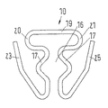
典型的な場合、プロファイルクランプとして具体化、すなわち形成される管クランプ1は、弾性復元可能なブリッジ4によって相互に接続される2つのハーフシェル2,3を持った締結バンドを有する。これら2つのハーフシェル2、3は、プロファイルクランプから知られているように、断面がおおよそ台形の形状を有する。単一の部品として具体化、すなわち形成された締結バンドを用いることもできる。
In the typical case, the tube clamp 1 embodied as a profile clamp, i.e. formed, has a fastening band with two half-
第1のハーフシェル2は、第1の張力付与ヘッド6を持つ第1の端5を有する。第2のハーフシェル3は、第2の張力付与ヘッド8を持つ第2の端7を有する。ねじ部材の形態での張力付与部材9は、第1の張力付与ヘッド6を通って誘導される。以下に説明するように、ばね部材10は張力付与部材9と係合して張力付与部材9と第1の張力付与ヘッド6との間に作用する。張力付与部材9は第2の張力付与ヘッド8と係合可能である。張力付与部材9をねじ込むことができるナット11は、第2の張力付与ヘッド8に設けられている。
The
この種のパイプクランプを組み付けるため、パイプクランプ1が組み付けられるべき配管を通じてパイプクランプ1を誘導することができるような充分大きな開口が張力付与部材9と第2の張力付与ヘッド8との間に出現するように、2つのハーフシェル2,3を相互に離して開かなければならない。この点に関し、パイプクランプ1がその組み付け場所に配された場合、図1に例示したように、2つのハーフシェル2,3の位置を相互に大雑把に決めるようにブリッジ4が設計されている。次に、専門技術者はパイプクランプ1を締め付けるために張力付与部材9を第2の張力付与ヘッド8と係合させ、すなわちこの典型的な実施形態においては、ねじ部材をナット11に単にねじ込む必要がある。
In order to assemble this kind of pipe clamp, a sufficiently large opening appears between the
この状態において、2つの張力付与ヘッド6,8が相互に平行に並んでいないことを図1にて困難を伴うことなく認識することが可能である。これは、それ自体が第2の張力付与ヘッド8への張力付与部材9のねじ込みを妨げよう。しかしながら、この場合にはばね部材10が第1の張力付与ヘッド6に対する張力付与部材9の整列を確実にし、張力付与部材9が第2の張力付与ヘッド8のナット11を向くように選択される。管クランプ1が望ましい組み付け位置に配された場合、2つの張力付与ヘッド6,8が相互に引き寄せられてより近づくように、専門技術者は2つのハーフシェル2,3を依然として相互に押し付ける必要があるだけである。この場合、実質的な追加の作業なしで張力付与部材9を第2の張力付与ヘッド8にあるナット11と係合させることができ、それでパイプクランプ1を締め付けることができるようになっている。
In this state, it can be recognized without difficulty in FIG. 1 that the two
図2から図6は、この種の整列をどのように達成することができるのかについて、さらなる詳細を例示する。 2-6 illustrate further details on how this type of alignment can be achieved.
図5は、頭部12とねじ部13とを有するねじ部材として具体化、すなわち形成した張力付与部材9を示す。頭部12は、それ自体知られた方法でねじり接触面、例えば外面六角形または六角穴を有することができる。
FIG. 5 shows the tensioning
頭部12とねじ部13との間には装着構造14が与えられている。典型的な場合、装着構造14は円周溝15として具体化、すなわち形成される。他の装着構造、例えば頭部12とねじ部13との間の突起が可能である。
A mounting
ばね部材10が極めて詳細に図2から図4に例示される。このばね部材10は、2つのばねクリップ17,18によって確定された収容空間16を有する。図3に示すように、2つのばねクリップ17,18は、収容空間16の領域にある平面内に設けられている。この平面において、ばねクリップ17,18は収容空間16をさらに形成する膨らみを有する。ばね部材10の無負荷状態における収容空間16は、頭部12とねじ部13との間の張力付与部材9の直径よりも若干小さな直径を有する。収容空間16の直径を張力付与部材9の溝15の領域の直径に対応させることができる。しかしながら、ばねクリップ17,18の一定の張力付与を伴ってばね部材10を張力付与部材9に取り付けることができるように、これを僅かに小さくすることも可能である。
The
2つのばねクリップ17,18は接続ボウ19によって相互に接続されている。接続ボウ19は、湾曲部20を介してばねクリップ17へと曲がり、湾曲部21を介してばねクリップ18へと曲がっている。湾曲部20,21はおよそ180°を越えて延在する。
The two
接続ボウ19は相対的に大きな長さを有する。すなわち、接続ボウ19はばねクリップ17,18間の最小間隔よりも長く、収容空間16の領域におけるばねクリップ17,18間の最大間隔よりも充分に長い。2つの湾曲部20,21は、ばねクリップ17,18を横に越えて突出することができる。ばね部材10が張力付与部材9に対して滑動した場合の接続ボウ19の塑性変形の危険性をこれによって小さく維持することができる。従って、ばね特性が代わりに維持される。
The
ばねクリップ17は、ばねアーム22によって端部23に接続されている。ばねクリップ18は、ばねアーム24によって端部25に接続されている。2つの端部23,25は内側に曲がった脚部26,27を有することができる。
The
図3にて認識することができるように、端部23,25は、以下に「第1の平面」として記述する2つのばねクリップ17,18が設けられる平面に対して傾斜している。端部23,25は、脚部26,27が第1の張力付与ヘッド6の内側、すなわち第2の張力付与ヘッド8を向く側に対して圧迫するように、第1の張力付与ヘッド6の方向(図6参照)に延在する。
As can be seen in FIG. 3, the ends 23, 25 are inclined with respect to the plane in which the two
図3にて認識されるように、接続ボウ19は第1の平面の外側に配置されている。これは第1の平面に対して脚部26,27の逆方向にオフセットしている。従って、2つの湾曲部20,21は第1の平面に対して傾斜する。第1の平面に関する湾曲部20,21の傾きは、第1の平面に関する端部23,25の傾き以外の異なる角度を有することができる。
As can be seen in FIG. 3, the
図6にて認識することができるように、接続ボウ19および脚部26は、共通の「第2の平面」にある。この第2の平面は、第1の張力付与ヘッド6の内側により形成される。例示したように、張力付与部材9が収容空間16を通って延在する(と共にばねクリップ17,18が溝15に収容された)場合、張力付与部材9の長手方向軸線28は、ばねクリップ17,18および収容空間16の第1の平面と直角に方向付けられる。第1の平面と第2の平面とが相互にあらかじめ設定された角度を取り囲んでいるので、張力付与部材9の長手方向軸線28は第1の張力付与ヘッド6の開口30の軸線29に対してこの角度で方向付けられる。図1にて認識することができるように、軸線29は第1の張力付与ヘッド6に対して直交し、張力付与部材9が第1の張力付与ヘッド6に対してあらかじめ設定された配置状態を得、張力付与部材9がほとんど努力せずに第2の張力付与ヘッド8へとねじ込まれ、そして第2の張力付与ヘッド8と係合することを可能にするようになっている。
As can be seen in FIG. 6, the connecting
図3にて認識されるように、ばねアーム22,24は第1の平面に対して傾斜、すなわち湾曲部20,21と同じ方向に傾斜している。第1の平面に対するばねアーム22,24の傾斜角は、第1の平面に対する湾曲部20,21の傾斜角と単に同じであって良いが、これは絶対的に必須ではない。
As can be seen in FIG. 3, the
ばねアーム22,24は、接続ボウ19から離れて対向するばねクリップ17,18の端から再び接続ボウ19へと延在する。このように、ばねアーム22、24が収容空間16を越えて延在し、また少なくとも部分的に湾曲部20,21に重なることさえ可能である。従って、ばねアーム22,24に相対的に大きな長さを与えてばね部材10のばねの特性に都合の良い変化をもたらすことが可能である。さらにまた、端部23,25を相対的に長く作ることも可能である。
The
図7から図9は、同一の部材に図2から図4と同じ参照符号を与えたばね部材10'の単純化した一実施形態を示す。この実施形態において、端部23',25'はばねクリップ17,18に直接接続している。この種のばね部材10'に関し、張力付与部材9を第1の張力付与ヘッド6に対して大体直角に整列させることが可能である。さらにまた、組み付けに関し、張力付与部材9を第2の張力付与ヘッド8と係合させるために張力付与部材9の両端を(パイプクランプ1の配置状態に関して)径方向内側に押圧することが単に必要なだけである。先導尖端を持った相対的に短い張力付与部材9のため、張力付与部材9を押し下げることなく第2の張力付与ヘッド8への挿入も可能である。
FIGS. 7 to 9 show a simplified embodiment of a
ばね部材10,10'は、線ばねとして具体化、すなわち形成される。換言すれば、弾性復元可能な特性を有する素線、すなわちばねワイヤーは、ばね部材10,10'の形状に曲げられる。この素線を金属製ワイヤーとして具体化、すなわち形成することができ、これはパイプクランプを高い雰囲気温度にて用いる場合に推奨される。しかしながら、例えば使用する場所の雰囲気温度が低い場合には、素線をプラスチックまたは他の材料から形成することも可能である。必要に応じて素線の断面を選択することができる。素線のばね部材10,10'、すなわち曲げ素線部に代えて、曲げ板金部または曲げ穿孔部をばね部材として用いることも可能である。
The
ばね部材10,10'は、軸線方向の事前応力に加え、張力付与部材9の軸線に対して径方向の事前応力をも張力付与部材9に作り出す。張力付与部材9をボルトとして具体化、すなわち形成した場合、ばね部材10,10'は不注意による張力付与部材9の緩みを阻止するための規定の抵抗トルクをさらに作り出す。例えば張力付与部材9がねじを切ったナット11とさらに係合した場合、実質的な量の軸線方向の張力がもはや存在せず、例えば自動車のモータによって発生する振動は、張力付与部材9を第1の張力付与ヘッド6から抜け外させてしまう可能性がある。しかしながら、この欠点は、ばね部材10,10'が軸線または径方向の充分な張力を張力付与部材9に加えるという本発明の実施形態によって阻止されよう。他方、ボルトの締め付けのために必要とされる締め付けトルクがばね部材10,10'によって実質的に増大しないので、ばね部材10,10'は張力付与部材9の組み付けを妨げない。さらに、張力付与部材9をあらかじめ決まった範囲内に配することができるので、組み付け中の容易化を結果として生ずる。
The
前述の実施形態が単に説明の目的のためにだけ与えられ、本発明を限定するように決して解釈されないことを指摘しておく。典型的な実施形態を参照して本発明を説明したけれども、ここで用いた文言は、限定文言というよりはむしろ、説明および例示の文言であることを理解されたい。その形態において本発明の範囲および精神から逸脱することなく、現状および補正されるような添付の特許請求の範囲内で変更を行うことができる。特定の手段や材料および実施形態を参照して本発明を記述したけれども、本発明はここで開示した事項に限定することを意図しておらず、むしろ本発明は添付の特許請求の範囲内にある如きすべての機能的に等しい構造や方法および利用へと拡張される。 It should be pointed out that the foregoing embodiments are given merely for illustrative purposes and are not to be construed as limiting the invention in any way. Although the present invention has been described with reference to exemplary embodiments, it is to be understood that the language used herein is illustrative and exemplary rather than limiting. Changes may be made in the form within the scope of the appended claims as modified and as such without departing from the scope and spirit of the invention. Although the invention has been described with reference to specific means, materials and embodiments, the invention is not intended to be limited to the matter disclosed herein, but rather is within the scope of the appended claims. It extends to all such functionally equivalent structures, methods and uses.
Claims (14)
前記第1の張力付与ヘッドを通って誘導可能に誘導されると共に前記第2の張力付与ヘッドと係合可能な張力付与部材と、
前記張力付与部材を紛失しないように確保するため、前記第1の張力付与ヘッドに構成されて設けられ、かつ前記張力付与部材と前記第1の張力付与ヘッドとの間で作動するように構成されて設けられたばね部材を具えた確保部材と
を具えたパイプクランプであって、
前記ばね部材は、前記張力付与部材のための収容空間を形成するように設けられた2つのばねクリップと、第1の平面に対して傾斜またはオフセットするように方向付けられると共に前記ばねクリップの少なくとも一方に接続する端部と、前記ばねクリップを相互に接続するように構成されて設けられる接続ボウとを具え、
前記収容空間の領域にある前記ばねクリップが前記第1の平面に配され、前記接続ボウは前記第1の平面の外側に設けられていることを特徴とするパイプクランプ。 A fastening band having a first end with a first tensioning head and a second end with a second tensioning head;
A tensioning member that is steerably guided through the first tensioning head and engageable with the second tensioning head;
In order to ensure that the tension applying member is not lost, the tension applying member is configured and provided in the first tension applying head, and is configured to operate between the tension applying member and the first tension applying head. A pipe clamp having a securing member provided with a spring member,
The spring member is oriented so as to be inclined or offset with respect to a first plane and at least one of the spring clips , the two spring clips being provided to form a receiving space for the tensioning member Comprising an end connected to one side and a connection bow configured and provided to connect the spring clips to each other;
The spring clip is disposed in said first plane, said connecting bow pipe clamp, characterized in that provided on the outer side of the first plane in the region of the accommodating space.
Applications Claiming Priority (2)
| Application Number | Priority Date | Filing Date | Title |
|---|---|---|---|
| EP12005476.2A EP2690338B1 (en) | 2012-07-27 | 2012-07-27 | Pipe clamp, in particular profile clamp |
| EP12005476.2 | 2012-07-27 |
Publications (2)
| Publication Number | Publication Date |
|---|---|
| JP2014025582A JP2014025582A (en) | 2014-02-06 |
| JP5805143B2 true JP5805143B2 (en) | 2015-11-04 |
Family
ID=46642320
Family Applications (1)
| Application Number | Title | Priority Date | Filing Date |
|---|---|---|---|
| JP2013124027A Expired - Fee Related JP5805143B2 (en) | 2012-07-27 | 2013-06-12 | Pipe clamp, especially profile clamp |
Country Status (9)
| Country | Link |
|---|---|
| US (1) | US9243731B2 (en) |
| EP (1) | EP2690338B1 (en) |
| JP (1) | JP5805143B2 (en) |
| KR (1) | KR101513133B1 (en) |
| CN (1) | CN103574171B (en) |
| BR (1) | BR102013018227A2 (en) |
| ES (1) | ES2548828T3 (en) |
| RS (1) | RS54301B1 (en) |
| RU (1) | RU2535452C1 (en) |
Families Citing this family (16)
| Publication number | Priority date | Publication date | Assignee | Title |
|---|---|---|---|---|
| DE102014103683A1 (en) | 2014-03-18 | 2015-09-24 | Norma Germany Gmbh | profile clip |
| NL2013873B1 (en) * | 2014-11-25 | 2016-10-11 | Walraven Holding Bv J Van | Pipe clip with screw retainer. |
| US20170184222A1 (en) * | 2015-12-28 | 2017-06-29 | Seth E. Aker | Pipe Suspension Clamp Hanger |
| US10903632B2 (en) | 2016-02-05 | 2021-01-26 | Hellermanntyton Corporation | Adjustable P-clamp with multiple mounting options |
| US10119631B2 (en) * | 2016-02-05 | 2018-11-06 | Hellermanntyton Corporation | Adjustable p-clamp |
| DE102016103986B3 (en) * | 2016-03-04 | 2017-08-24 | Norma Germany Gmbh | Prepositioner for a profile clamp and connection arrangement with such a pre-positioner |
| DE102016115536A1 (en) | 2016-08-22 | 2018-02-22 | Norma Germany Gmbh | safety claw |
| CN109253144A (en) | 2017-07-12 | 2019-01-22 | 德国诺玛公司 | Comprising having the configuration fixture of the screw of reducing diameter part |
| JP7257015B2 (en) * | 2017-07-18 | 2023-04-13 | 株式会社Tjmデザイン | utensil holder |
| CN108223395A (en) * | 2018-03-21 | 2018-06-29 | 郑旭 | Electronic water pump for automobile |
| CN108437732B (en) * | 2018-04-13 | 2023-07-04 | 无锡市东鹏金属制品有限公司 | Clamp casting of shock-absorbing suspension device for automobile |
| RU182663U1 (en) * | 2018-04-17 | 2018-08-28 | Общество с ограниченной ответственностью "ИГЛУС" | BOXING OF THE NECK OF THE BOX |
| MX2021001309A (en) | 2018-08-07 | 2021-06-23 | Ideal Clamp Products Inc | Retainer for clamp assembly. |
| DE102018131671A1 (en) * | 2018-12-11 | 2020-06-18 | Ihi Charging Systems International Gmbh | Clamp and exhaust gas turbocharger with such a clamp |
| US11371630B2 (en) | 2019-03-29 | 2022-06-28 | ASC Engineered Solutions, LLC | Pivot clip |
| DE102019112884B3 (en) * | 2019-05-16 | 2020-03-26 | Norma Germany Gmbh | Device for pre-positioning a clamp and connection system |
Family Cites Families (17)
| Publication number | Priority date | Publication date | Assignee | Title |
|---|---|---|---|---|
| GB447963A (en) * | 1935-12-16 | 1936-05-28 | Frederick Pritchard | Improvements in clips for hose and the like |
| DE8806714U1 (en) * | 1988-05-21 | 1988-08-25 | Flamco B.V., Gouda, Nl | |
| JP3397843B2 (en) | 1993-07-23 | 2003-04-21 | 株式会社リコー | Copier |
| US5720086A (en) * | 1993-10-19 | 1998-02-24 | Aba Of Sweden Ab | Clamping collar |
| JP2600624Y2 (en) * | 1993-12-13 | 1999-10-18 | 愛知機械工業株式会社 | Idler pulley adjustment bolt prevention structure |
| JPH11141764A (en) * | 1997-11-04 | 1999-05-28 | Riken Corp | Split pipe joint |
| DE20202244U1 (en) * | 2002-02-15 | 2003-06-26 | Vieregge Uwe | Coupling for connecting two pipes |
| SE524585C2 (en) * | 2002-03-04 | 2004-08-31 | Aba Sweden Ab | Pipe coupling device comprising two articulated halves |
| JP4068368B2 (en) * | 2002-03-13 | 2008-03-26 | 株式会社アカギ | Vertical band for piping |
| JP2005003014A (en) * | 2003-06-09 | 2005-01-06 | Akagi:Kk | Method and tool for preventing corotation of pipe supporting tool |
| FR2863335B1 (en) * | 2003-12-04 | 2007-11-02 | Caillau Ets | TIGHTENING NECK |
| CN2763663Y (en) * | 2004-11-02 | 2006-03-08 | 浙江东亚阀门有限公司 | Active pipe clamp |
| US20070052239A1 (en) | 2005-08-24 | 2007-03-08 | Victaulic Company Of America | Stop assembly for pipe couplings |
| JP4954118B2 (en) * | 2008-02-25 | 2012-06-13 | 中国電力株式会社 | Auxiliary tool for temporarily fixing bolts |
| JP2010121708A (en) * | 2008-11-19 | 2010-06-03 | Bc Seisakusho:Kk | Nut falling-off preventive clip |
| DE102009039862B4 (en) * | 2009-09-03 | 2013-04-18 | Norma Germany Gmbh | profile clip |
| JP5389719B2 (en) * | 2010-01-28 | 2014-01-15 | 株式会社ビーシー製作所 | Nut drop prevention clip |
-
2012
- 2012-07-27 EP EP12005476.2A patent/EP2690338B1/en not_active Not-in-force
- 2012-07-27 RS RS20150673A patent/RS54301B1/en unknown
- 2012-07-27 ES ES12005476.2T patent/ES2548828T3/en active Active
-
2013
- 2013-06-12 JP JP2013124027A patent/JP5805143B2/en not_active Expired - Fee Related
- 2013-07-05 CN CN201310280674.7A patent/CN103574171B/en not_active Expired - Fee Related
- 2013-07-10 US US13/938,716 patent/US9243731B2/en not_active Expired - Fee Related
- 2013-07-12 RU RU2013132372/06A patent/RU2535452C1/en not_active IP Right Cessation
- 2013-07-17 BR BRBR102013018227-3A patent/BR102013018227A2/en not_active IP Right Cessation
- 2013-07-22 KR KR1020130086285A patent/KR101513133B1/en active IP Right Grant
Also Published As
| Publication number | Publication date |
|---|---|
| US20140028014A1 (en) | 2014-01-30 |
| EP2690338A1 (en) | 2014-01-29 |
| CN103574171B (en) | 2016-06-29 |
| BR102013018227A2 (en) | 2014-12-23 |
| ES2548828T3 (en) | 2015-10-21 |
| JP2014025582A (en) | 2014-02-06 |
| RU2535452C1 (en) | 2014-12-10 |
| EP2690338B1 (en) | 2015-07-22 |
| KR20140013961A (en) | 2014-02-05 |
| CN103574171A (en) | 2014-02-12 |
| KR101513133B1 (en) | 2015-04-17 |
| RS54301B1 (en) | 2016-02-29 |
| US9243731B2 (en) | 2016-01-26 |
Similar Documents
| Publication | Publication Date | Title |
|---|---|---|
| JP5805143B2 (en) | Pipe clamp, especially profile clamp | |
| JP5542679B2 (en) | Hose clamp | |
| RU134280U1 (en) | PROFILE CLAMP WITH PRELIMINARY POSITIONING DEVICE | |
| US9631657B2 (en) | Fastening element and assembly with such a fastening element and a receiving element | |
| JP2008095960A (en) | Hose clamp | |
| JP2012177473A (en) | Tension clamp | |
| US9151421B2 (en) | Profiled clamp | |
| US10982801B2 (en) | Profiled clamp | |
| US20100058563A1 (en) | Clamp Securement | |
| US10794518B2 (en) | Profile clamp having sealing element | |
| JP2014095472A (en) | Screw connection device for pipe, in particular pipe for vehicle installed with engine | |
| JP2014190538A (en) | Long material fixing metal fitting | |
| JP7381203B2 (en) | tube clip | |
| US20150068016A1 (en) | Hose Clamp Fastener Locking Device | |
| JP2019128037A5 (en) | ||
| JP5693939B2 (en) | Equipment fixture | |
| KR200477672Y1 (en) | Clamp Guide and Clamp Assembly Including The Same | |
| JP7473276B2 (en) | Hose Fixtures | |
| US11953132B2 (en) | Hose clamp | |
| KR101097875B1 (en) | Hose clamp | |
| JP7292083B2 (en) | connector | |
| CN112567162B (en) | Retainer for clamp assembly | |
| CN113175570A (en) | Pipe hoop | |
| RU26628U1 (en) | REPLACEMENT DEVICE FOR REPEATED USE (OPTIONS) | |
| JP2022521820A (en) | Locator system and method for hose clamps |
Legal Events
| Date | Code | Title | Description |
|---|---|---|---|
| A977 | Report on retrieval |
Free format text: JAPANESE INTERMEDIATE CODE: A971007 Effective date: 20140408 |
|
| A131 | Notification of reasons for refusal |
Free format text: JAPANESE INTERMEDIATE CODE: A131 Effective date: 20140415 |
|
| A521 | Written amendment |
Free format text: JAPANESE INTERMEDIATE CODE: A523 Effective date: 20140714 |
|
| A131 | Notification of reasons for refusal |
Free format text: JAPANESE INTERMEDIATE CODE: A131 Effective date: 20141202 |
|
| A521 | Written amendment |
Free format text: JAPANESE INTERMEDIATE CODE: A523 Effective date: 20150302 |
|
| TRDD | Decision of grant or rejection written | ||
| A01 | Written decision to grant a patent or to grant a registration (utility model) |
Free format text: JAPANESE INTERMEDIATE CODE: A01 Effective date: 20150804 |
|
| A61 | First payment of annual fees (during grant procedure) |
Free format text: JAPANESE INTERMEDIATE CODE: A61 Effective date: 20150901 |
|
| R150 | Certificate of patent or registration of utility model |
Ref document number: 5805143 Country of ref document: JP Free format text: JAPANESE INTERMEDIATE CODE: R150 |
|
| R250 | Receipt of annual fees |
Free format text: JAPANESE INTERMEDIATE CODE: R250 |
|
| LAPS | Cancellation because of no payment of annual fees |